US5885529A - Automated immunoassay analyzer - Google Patents
Automated immunoassay analyzerDownload PDFInfo
- Publication number
- US5885529A US5885529AUS08/672,654US67265496AUS5885529AUS 5885529 AUS5885529 AUS 5885529AUS 67265496 AUS67265496 AUS 67265496AUS 5885529 AUS5885529 AUS 5885529A
- Authority
- US
- United States
- Prior art keywords
- sample
- reaction tube
- station
- tube
- reagent
- Prior art date
- Legal status (The legal status is an assumption and is not a legal conclusion. Google has not performed a legal analysis and makes no representation as to the accuracy of the status listed.)
- Expired - Lifetime
Links
- 238000003018immunoassayMethods0.000titleclaimsabstractdescription69
- 239000011324beadSubstances0.000claimsabstractdescription216
- 239000003153chemical reaction reagentSubstances0.000claimsabstractdescription212
- 238000003556assayMethods0.000claimsabstractdescription67
- 238000012360testing methodMethods0.000claimsabstractdescription59
- 239000012530fluidSubstances0.000claimsabstractdescription52
- 238000005406washingMethods0.000claimsabstractdescription49
- 239000002699waste materialSubstances0.000claimsabstractdescription35
- 238000003860storageMethods0.000claimsabstractdescription16
- 239000012898sample dilutionSubstances0.000claimsabstractdescription15
- 238000006243chemical reactionMethods0.000claimsdescription233
- 239000012895dilutionSubstances0.000claimsdescription65
- 238000010790dilutionMethods0.000claimsdescription65
- 239000012620biological materialSubstances0.000claimsdescription49
- 239000012491analyteSubstances0.000claimsdescription42
- 238000001514detection methodMethods0.000claimsdescription40
- 230000033001locomotionEffects0.000claimsdescription26
- XLYOFNOQVPJJNP-UHFFFAOYSA-NwaterSubstancesOXLYOFNOQVPJJNP-UHFFFAOYSA-N0.000claimsdescription26
- 239000003085diluting agentSubstances0.000claimsdescription25
- 238000007789sealingMethods0.000claimsdescription23
- 238000009987spinningMethods0.000claimsdescription20
- 230000005484gravityEffects0.000claimsdescription12
- 239000000463materialSubstances0.000claimsdescription10
- 230000003028elevating effectEffects0.000claimsdescription8
- 230000001154acute effectEffects0.000claimsdescription7
- 239000000203mixtureSubstances0.000claimsdescription7
- 230000037361pathwayEffects0.000claimsdescription7
- 230000000694effectsEffects0.000claimsdescription6
- 230000000903blocking effectEffects0.000claimsdescription5
- 238000006073displacement reactionMethods0.000claimsdescription5
- 238000004891communicationMethods0.000claimsdescription4
- 239000008240homogeneous mixtureSubstances0.000claimsdescription4
- 238000013461designMethods0.000abstractdescription2
- 239000000523sampleSubstances0.000description192
- 238000000034methodMethods0.000description15
- 238000002156mixingMethods0.000description13
- 238000011068loading methodMethods0.000description11
- 239000004033plasticSubstances0.000description11
- 238000012545processingMethods0.000description11
- 239000000758substrateSubstances0.000description11
- 238000011534incubationMethods0.000description10
- 239000000427antigenSubstances0.000description9
- 102000036639antigensHuman genes0.000description9
- 108091007433antigensProteins0.000description9
- 238000007792additionMethods0.000description7
- 230000008569processEffects0.000description7
- 230000006870functionEffects0.000description6
- 239000007788liquidSubstances0.000description6
- 238000005070samplingMethods0.000description6
- 239000007787solidSubstances0.000description6
- 238000012546transferMethods0.000description6
- 230000032258transportEffects0.000description6
- 102000002260Alkaline PhosphataseHuman genes0.000description5
- 108020004774Alkaline PhosphataseProteins0.000description5
- BVTJGGGYKAMDBN-UHFFFAOYSA-NDioxetaneChemical compoundC1COO1BVTJGGGYKAMDBN-UHFFFAOYSA-N0.000description5
- 238000004458analytical methodMethods0.000description5
- 238000004140cleaningMethods0.000description5
- 238000005259measurementMethods0.000description5
- -1phosphate esterChemical class0.000description5
- 239000000243solutionSubstances0.000description5
- 230000002238attenuated effectEffects0.000description4
- 238000010586diagramMethods0.000description4
- 239000010808liquid wasteSubstances0.000description4
- 229910019142PO4Inorganic materials0.000description3
- 239000004743PolypropyleneSubstances0.000description3
- 230000009471actionEffects0.000description3
- 238000005119centrifugationMethods0.000description3
- 238000000354decomposition reactionMethods0.000description3
- 238000000605extractionMethods0.000description3
- 239000011888foilSubstances0.000description3
- 238000003780insertionMethods0.000description3
- 230000037431insertionEffects0.000description3
- 238000002372labellingMethods0.000description3
- 239000002184metalSubstances0.000description3
- 229910052751metalInorganic materials0.000description3
- 239000010452phosphateSubstances0.000description3
- 229920001155polypropylenePolymers0.000description3
- 102000004169proteins and genesHuman genes0.000description3
- 108090000623proteins and genesProteins0.000description3
- 102000004190EnzymesHuman genes0.000description2
- 108090000790EnzymesProteins0.000description2
- 150000001875compoundsChemical class0.000description2
- 238000011109contaminationMethods0.000description2
- 239000008367deionised waterSubstances0.000description2
- 229910021641deionized waterInorganic materials0.000description2
- 239000012470diluted sampleSubstances0.000description2
- 238000007598dipping methodMethods0.000description2
- KAKKHKRHCKCAGH-UHFFFAOYSA-Ldisodium;(4-nitrophenyl) phosphate;hexahydrateChemical compoundO.O.O.O.O.O.[Na+].[Na+].[O-][N+](=O)C1=CC=C(OP([O-])([O-])=O)C=C1KAKKHKRHCKCAGH-UHFFFAOYSA-L0.000description2
- 239000003814drugSubstances0.000description2
- 229940079593drugDrugs0.000description2
- 239000013536elastomeric materialSubstances0.000description2
- 238000011010flushing procedureMethods0.000description2
- 230000001900immune effectEffects0.000description2
- 238000002347injectionMethods0.000description2
- 239000007924injectionSubstances0.000description2
- 230000003993interactionEffects0.000description2
- 230000007246mechanismEffects0.000description2
- 239000002991molded plasticSubstances0.000description2
- 238000000465mouldingMethods0.000description2
- 230000007935neutral effectEffects0.000description2
- 230000003287optical effectEffects0.000description2
- 230000002093peripheral effectEffects0.000description2
- 210000002381plasmaAnatomy0.000description2
- 238000012913prioritisationMethods0.000description2
- 239000000047productSubstances0.000description2
- 238000011002quantificationMethods0.000description2
- 230000002285radioactive effectEffects0.000description2
- 230000004044responseEffects0.000description2
- 238000000926separation methodMethods0.000description2
- 239000002910solid wasteSubstances0.000description2
- 239000013589supplementSubstances0.000description2
- 238000013519translationMethods0.000description2
- 210000002700urineAnatomy0.000description2
- 230000000007visual effectEffects0.000description2
- 241000217377Amblema plicataSpecies0.000description1
- 208000035473Communicable diseaseDiseases0.000description1
- 229910000881Cu alloyInorganic materials0.000description1
- 206010020751HypersensitivityDiseases0.000description1
- 108060003951ImmunoglobulinProteins0.000description1
- 206010028980NeoplasmDiseases0.000description1
- 102000015731Peptide HormonesHuman genes0.000description1
- 108010038988Peptide HormonesProteins0.000description1
- 239000004809TeflonSubstances0.000description1
- 229920006362Teflon®Polymers0.000description1
- 230000001133accelerationEffects0.000description1
- 239000000853adhesiveSubstances0.000description1
- 230000001070adhesive effectEffects0.000description1
- 238000013019agitationMethods0.000description1
- 208000026935allergic diseaseDiseases0.000description1
- 230000007815allergyEffects0.000description1
- 230000003466anti-cipated effectEffects0.000description1
- 238000013459approachMethods0.000description1
- 238000005452bendingMethods0.000description1
- 230000008901benefitEffects0.000description1
- DMFGNRRURHSENX-UHFFFAOYSA-Nberyllium copperChemical group[Be].[Cu]DMFGNRRURHSENX-UHFFFAOYSA-N0.000description1
- 210000004369bloodAnatomy0.000description1
- 239000008280bloodSubstances0.000description1
- 210000001124body fluidAnatomy0.000description1
- 238000011088calibration curveMethods0.000description1
- 230000015556catabolic processEffects0.000description1
- 210000001175cerebrospinal fluidAnatomy0.000description1
- 239000002131composite materialSubstances0.000description1
- 230000006835compressionEffects0.000description1
- 238000007906compressionMethods0.000description1
- 239000000470constituentSubstances0.000description1
- 238000010276constructionMethods0.000description1
- 238000007796conventional methodMethods0.000description1
- 238000005260corrosionMethods0.000description1
- 230000007797corrosionEffects0.000description1
- 230000008878couplingEffects0.000description1
- 238000010168coupling processMethods0.000description1
- 238000005859coupling reactionMethods0.000description1
- 238000006731degradation reactionMethods0.000description1
- 238000000151depositionMethods0.000description1
- 230000003292diminished effectEffects0.000description1
- 229920001971elastomerPolymers0.000description1
- 150000002148estersChemical class0.000description1
- 238000001704evaporationMethods0.000description1
- 230000008020evaporationEffects0.000description1
- 239000013505freshwaterSubstances0.000description1
- 230000007274generation of a signal involved in cell-cell signalingEffects0.000description1
- 239000011521glassSubstances0.000description1
- 239000003163gonadal steroid hormoneSubstances0.000description1
- 239000000122growth hormoneSubstances0.000description1
- 238000010438heat treatmentMethods0.000description1
- 238000000703high-speed centrifugationMethods0.000description1
- 230000008105immune reactionEffects0.000description1
- 102000018358immunoglobulinHuman genes0.000description1
- 230000006872improvementEffects0.000description1
- 238000001746injection mouldingMethods0.000description1
- 238000007689inspectionMethods0.000description1
- 150000002500ionsChemical class0.000description1
- 238000005304joiningMethods0.000description1
- 238000011005laboratory methodMethods0.000description1
- 239000007791liquid phaseSubstances0.000description1
- 230000014759maintenance of locationEffects0.000description1
- 238000007726management methodMethods0.000description1
- 230000013011matingEffects0.000description1
- 230000004048modificationEffects0.000description1
- 238000012986modificationMethods0.000description1
- 238000010137moulding (plastic)Methods0.000description1
- 230000000737periodic effectEffects0.000description1
- RXNXLAHQOVLMIE-UHFFFAOYSA-Nphenyl 10-methylacridin-10-ium-9-carboxylateChemical compoundC12=CC=CC=C2[N+](C)=C2C=CC=CC2=C1C(=O)OC1=CC=CC=C1RXNXLAHQOVLMIE-UHFFFAOYSA-N0.000description1
- NBIIXXVUZAFLBC-UHFFFAOYSA-KphosphateChemical compound[O-]P([O-])([O-])=ONBIIXXVUZAFLBC-UHFFFAOYSA-K0.000description1
- 238000005375photometryMethods0.000description1
- 238000002360preparation methodMethods0.000description1
- 238000002203pretreatmentMethods0.000description1
- 102000004196processed proteins & peptidesHuman genes0.000description1
- 108090000765processed proteins & peptidesProteins0.000description1
- 230000001681protective effectEffects0.000description1
- 238000005086pumpingMethods0.000description1
- 230000009467reductionEffects0.000description1
- 230000003252repetitive effectEffects0.000description1
- 239000005060rubberSubstances0.000description1
- 210000003296salivaAnatomy0.000description1
- 210000002966serumAnatomy0.000description1
- 238000004513sizingMethods0.000description1
- 150000003384small moleculesChemical class0.000description1
- 239000010935stainless steelSubstances0.000description1
- 229910001220stainless steelInorganic materials0.000description1
- 150000003431steroidsChemical class0.000description1
- 229920003048styrene butadiene rubberPolymers0.000description1
- 239000000126substanceSubstances0.000description1
- 230000000153supplemental effectEffects0.000description1
- 229940126585therapeutic drugDrugs0.000description1
- 229920001169thermoplasticPolymers0.000description1
- 239000012815thermoplastic materialSubstances0.000description1
- 239000004416thermosoftening plasticSubstances0.000description1
- 210000001685thyroid glandAnatomy0.000description1
- 239000012780transparent materialSubstances0.000description1
- 239000011782vitaminSubstances0.000description1
- 229940088594vitaminDrugs0.000description1
- 229930003231vitaminNatural products0.000description1
- 235000013343vitaminNutrition0.000description1
- 238000004804windingMethods0.000description1
- 239000002023woodSubstances0.000description1
Images


Classifications
- B—PERFORMING OPERATIONS; TRANSPORTING
- B01—PHYSICAL OR CHEMICAL PROCESSES OR APPARATUS IN GENERAL
- B01L—CHEMICAL OR PHYSICAL LABORATORY APPARATUS FOR GENERAL USE
- B01L3/00—Containers or dishes for laboratory use, e.g. laboratory glassware; Droppers
- B01L3/50—Containers for the purpose of retaining a material to be analysed, e.g. test tubes
- B01L3/508—Containers for the purpose of retaining a material to be analysed, e.g. test tubes rigid containers not provided for above
- B01L3/5085—Containers for the purpose of retaining a material to be analysed, e.g. test tubes rigid containers not provided for above for multiple samples, e.g. microtitration plates
- B01L3/50853—Containers for the purpose of retaining a material to be analysed, e.g. test tubes rigid containers not provided for above for multiple samples, e.g. microtitration plates with covers or lids
- G—PHYSICS
- G01—MEASURING; TESTING
- G01N—INVESTIGATING OR ANALYSING MATERIALS BY DETERMINING THEIR CHEMICAL OR PHYSICAL PROPERTIES
- G01N35/00—Automatic analysis not limited to methods or materials provided for in any single one of groups G01N1/00 - G01N33/00; Handling materials therefor
- G01N35/02—Automatic analysis not limited to methods or materials provided for in any single one of groups G01N1/00 - G01N33/00; Handling materials therefor using a plurality of sample containers moved by a conveyor system past one or more treatment or analysis stations
- G—PHYSICS
- G01—MEASURING; TESTING
- G01N—INVESTIGATING OR ANALYSING MATERIALS BY DETERMINING THEIR CHEMICAL OR PHYSICAL PROPERTIES
- G01N35/00—Automatic analysis not limited to methods or materials provided for in any single one of groups G01N1/00 - G01N33/00; Handling materials therefor
- G01N35/10—Devices for transferring samples or any liquids to, in, or from, the analysis apparatus, e.g. suction devices, injection devices
- G01N35/1002—Reagent dispensers
- G—PHYSICS
- G01—MEASURING; TESTING
- G01N—INVESTIGATING OR ANALYSING MATERIALS BY DETERMINING THEIR CHEMICAL OR PHYSICAL PROPERTIES
- G01N35/00—Automatic analysis not limited to methods or materials provided for in any single one of groups G01N1/00 - G01N33/00; Handling materials therefor
- G01N2035/00346—Heating or cooling arrangements
- G01N2035/00435—Refrigerated reagent storage
- G—PHYSICS
- G01—MEASURING; TESTING
- G01N—INVESTIGATING OR ANALYSING MATERIALS BY DETERMINING THEIR CHEMICAL OR PHYSICAL PROPERTIES
- G01N35/00—Automatic analysis not limited to methods or materials provided for in any single one of groups G01N1/00 - G01N33/00; Handling materials therefor
- G01N35/02—Automatic analysis not limited to methods or materials provided for in any single one of groups G01N1/00 - G01N33/00; Handling materials therefor using a plurality of sample containers moved by a conveyor system past one or more treatment or analysis stations
- G01N35/04—Details of the conveyor system
- G01N2035/0401—Sample carriers, cuvettes or reaction vessels
- G01N2035/0403—Sample carriers with closing or sealing means
- G01N2035/0405—Sample carriers with closing or sealing means manipulating closing or opening means, e.g. stoppers, screw caps, lids or covers
- G—PHYSICS
- G01—MEASURING; TESTING
- G01N—INVESTIGATING OR ANALYSING MATERIALS BY DETERMINING THEIR CHEMICAL OR PHYSICAL PROPERTIES
- G01N35/00—Automatic analysis not limited to methods or materials provided for in any single one of groups G01N1/00 - G01N33/00; Handling materials therefor
- G01N35/02—Automatic analysis not limited to methods or materials provided for in any single one of groups G01N1/00 - G01N33/00; Handling materials therefor using a plurality of sample containers moved by a conveyor system past one or more treatment or analysis stations
- G01N35/04—Details of the conveyor system
- G01N2035/0439—Rotary sample carriers, i.e. carousels
- G01N2035/0451—Rotary sample carriers, i.e. carousels composed of interchangeable sectors
- Y—GENERAL TAGGING OF NEW TECHNOLOGICAL DEVELOPMENTS; GENERAL TAGGING OF CROSS-SECTIONAL TECHNOLOGIES SPANNING OVER SEVERAL SECTIONS OF THE IPC; TECHNICAL SUBJECTS COVERED BY FORMER USPC CROSS-REFERENCE ART COLLECTIONS [XRACs] AND DIGESTS
- Y10—TECHNICAL SUBJECTS COVERED BY FORMER USPC
- Y10T—TECHNICAL SUBJECTS COVERED BY FORMER US CLASSIFICATION
- Y10T436/00—Chemistry: analytical and immunological testing
- Y10T436/11—Automated chemical analysis
- Y10T436/113332—Automated chemical analysis with conveyance of sample along a test line in a container or rack
- Y10T436/114165—Automated chemical analysis with conveyance of sample along a test line in a container or rack with step of insertion or removal from test line
- Y—GENERAL TAGGING OF NEW TECHNOLOGICAL DEVELOPMENTS; GENERAL TAGGING OF CROSS-SECTIONAL TECHNOLOGIES SPANNING OVER SEVERAL SECTIONS OF THE IPC; TECHNICAL SUBJECTS COVERED BY FORMER USPC CROSS-REFERENCE ART COLLECTIONS [XRACs] AND DIGESTS
- Y10—TECHNICAL SUBJECTS COVERED BY FORMER USPC
- Y10T—TECHNICAL SUBJECTS COVERED BY FORMER US CLASSIFICATION
- Y10T436/00—Chemistry: analytical and immunological testing
- Y10T436/11—Automated chemical analysis
- Y10T436/113332—Automated chemical analysis with conveyance of sample along a test line in a container or rack
- Y10T436/114998—Automated chemical analysis with conveyance of sample along a test line in a container or rack with treatment or replacement of aspirator element [e.g., cleaning, etc.]
- Y—GENERAL TAGGING OF NEW TECHNOLOGICAL DEVELOPMENTS; GENERAL TAGGING OF CROSS-SECTIONAL TECHNOLOGIES SPANNING OVER SEVERAL SECTIONS OF THE IPC; TECHNICAL SUBJECTS COVERED BY FORMER USPC CROSS-REFERENCE ART COLLECTIONS [XRACs] AND DIGESTS
- Y10—TECHNICAL SUBJECTS COVERED BY FORMER USPC
- Y10T—TECHNICAL SUBJECTS COVERED BY FORMER US CLASSIFICATION
- Y10T436/00—Chemistry: analytical and immunological testing
- Y10T436/11—Automated chemical analysis
- Y10T436/115831—Condition or time responsive
- Y—GENERAL TAGGING OF NEW TECHNOLOGICAL DEVELOPMENTS; GENERAL TAGGING OF CROSS-SECTIONAL TECHNOLOGIES SPANNING OVER SEVERAL SECTIONS OF THE IPC; TECHNICAL SUBJECTS COVERED BY FORMER USPC CROSS-REFERENCE ART COLLECTIONS [XRACs] AND DIGESTS
- Y10—TECHNICAL SUBJECTS COVERED BY FORMER USPC
- Y10T—TECHNICAL SUBJECTS COVERED BY FORMER US CLASSIFICATION
- Y10T436/00—Chemistry: analytical and immunological testing
- Y10T436/25—Chemistry: analytical and immunological testing including sample preparation
- Y10T436/25375—Liberation or purification of sample or separation of material from a sample [e.g., filtering, centrifuging, etc.]
- Y—GENERAL TAGGING OF NEW TECHNOLOGICAL DEVELOPMENTS; GENERAL TAGGING OF CROSS-SECTIONAL TECHNOLOGIES SPANNING OVER SEVERAL SECTIONS OF THE IPC; TECHNICAL SUBJECTS COVERED BY FORMER USPC CROSS-REFERENCE ART COLLECTIONS [XRACs] AND DIGESTS
- Y10—TECHNICAL SUBJECTS COVERED BY FORMER USPC
- Y10T—TECHNICAL SUBJECTS COVERED BY FORMER US CLASSIFICATION
- Y10T436/00—Chemistry: analytical and immunological testing
- Y10T436/25—Chemistry: analytical and immunological testing including sample preparation
- Y10T436/25625—Dilution
- Y—GENERAL TAGGING OF NEW TECHNOLOGICAL DEVELOPMENTS; GENERAL TAGGING OF CROSS-SECTIONAL TECHNOLOGIES SPANNING OVER SEVERAL SECTIONS OF THE IPC; TECHNICAL SUBJECTS COVERED BY FORMER USPC CROSS-REFERENCE ART COLLECTIONS [XRACs] AND DIGESTS
- Y10—TECHNICAL SUBJECTS COVERED BY FORMER USPC
- Y10T—TECHNICAL SUBJECTS COVERED BY FORMER US CLASSIFICATION
- Y10T436/00—Chemistry: analytical and immunological testing
- Y10T436/25—Chemistry: analytical and immunological testing including sample preparation
- Y10T436/2575—Volumetric liquid transfer
Definitions
- the present inventionis generally relates to an automated immunoassay analyzer and, more particularly, to a high throughput automated immunoassay analyzer which permits high volume assay of a broad range of analytes in bodily fluids.
- An immunoassayis a well known laboratory method used to determine the amount of an analyte in a sample such as plasma or urine. It is based on the interaction of antibodies with antigens, and because of the degree of selectivity for the analyte (either antigen or antibody), an immunoassay can be used to quantitatively determine very low concentrations of drugs, hormones, polypeptides, or other analyte compounds found in a test sample. For many years, immunoassays were performed by hand by trained laboratory technicians.
- a sampleis mixed with a reagent and a solid support having a bound antigen or antibody, the sample is incubated such that the corresponding antigen or antibody in the sample and a labeled antigen or antibody provided in the reagent can be bound to the antigen or antibody on the solid support, then the solid support is thoroughly washed and the label (fluorescent, radioactive, chemiluminescent, or the like) is detected by an appropriate mechanism, and finally the analyte of interest (antigen or antibody) is quantified from the detected label.
- the labelfluorescent, radioactive, chemiluminescent, or the like
- a bead storage unitis included on-board the instrument for loading of assay tubes on the instrument comprising a plurality of bead cassettes mounted on a carousel.
- Each bead cassettestores a plurality of solid support beads as a column on a spiral track, where the beads exit the bottom of the spiral track into an open-air holding receptacle adjoining the outside of the base of the bead pack.
- the dispensed beadsare picked up by a vacuum-operated bead transport for feeding into a U-shaped reaction tube.
- immunoassay systemsare demanded which can handle high volume LIS based test ordering while retaining the capability of accepting test orders and any prioritizations directly from an operator.
- reduced user interfacee.g., tests are performed automatically from computer input
- an improved automated immunoassay analyzerallows for loading and specimen extraction from the original sample tubes loaded directly on-board the instrument, wherein a wide variety of different types of tests can be performed on any given sample by the provision of a bead pack carousel and a reagent carousel that can be computer controlled to allow automated picking, choosing and combining among the various beads and reagents with a sample on-board the instrument to conduct the test(s) desired for each sample.
- the analyzerhas a computer control which controls the selection of reagents and beads for performing a variety of immunoassays on a number of different samples which are loaded into the analyzer. In addition, the computer controls the timing of incubation, mixing, washing, and detection operations.
- FIG. 1is a generalized block diagram of the automated immunoassay analyzer
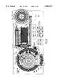
- FIG. 2Ais a plan view diagram of the flow path of samples and assays through the automated immunoassay analyzer
- FIG. 2Bis a partial schematic view diagram of the flow path of samples and assays through the automated immunoassay analyzer
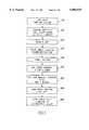
- FIG. 3is a flow chart of the processing steps performed on the assay tubes in the automated immunoassay analyzer
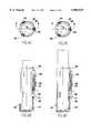
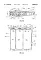
- FIG. 4Ais a cross-sectional side view of a rack with a sample container holder of the invention mounted on a carousel;
- FIG. 4Bis a fragmentary cross-sectional side view of an individual sample container holder sleeve of the invention holding a relatively small test tube;
- FIG. 4Cis a top view of the sample container holder sleeve of FIG. 4B;
- FIG. 4Dis a fragmentary cross-sectional side view of an individual sample container holder sleeve of the invention holding a relatively large test tube;
- FIG. 4Eis a top view of the sample container holder sleeve of FIG. 4D;
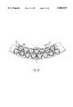
- FIG. 4Fis a top view of a carousel segment supporting a sample container rack of the invention.
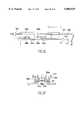
- FIG. 5Ais a fragmentary cross-sectional side view of a reagent container with re-sealable lid of the invention
- FIG. 5Bis a top view of the reagent container with re-sealable lid of FIG. 5A;
- FIG. 5Cis a rear view of the reagent container and re-sealable lid along the direction 5--5 indicated in FIG. 5B;
- FIG. 5Dis a fragmentary top view of the lid means of the invention.
- FIG. 5Eis a fragmentary side view along direction 5'--5' of FIG. 5B of the of the self-sealing horizontal arm of the lid means and ramp guide means system of the present invention
- FIG. 5Fis a fragmentary end view of along direction 5'--5' of FIG. 5B showing an interlocking ramp guide means and horizontal arm system for the lid means;
- FIG. 5Gis a side exterior view of a reagent container with a re-sealable lid of the invention in a closed position
- FIG. 5His a side exterior view of a reagent container with a re-sealable lid of the invention in an open position;
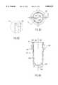
- FIG. 6is a cross-sectional view of a sample dilution well system of the invention.
- FIG. 7Ais a cross-sectional side view of a dispenser device of the invention.
- FIG. 7Bis a cross-sectional top view of the bead chamber and its plunger chamber from the perspective of direction B7--B7 indicated in FIG. 7A;
- FIG. 7Cis a fragmentary side perspective view of the bead track component of the dispenser device of FIG. 7A;
- FIG. 7Dis a fragmentary top perspective view of the plunger component of the dispenser device of FIG. 7A;
- FIG. 7Eis a fragmentary side perspective view of the plunger component of the dispenser device of FIG. 7A;
- FIG. 7Fis a cross-sectional top view of the bead chamber, bead track, and plunger biasing spring from the perspective of direction C7--C7 indicated in FIG. 7A;
- FIG. 7Gis a cross-sectional side view of a dispenser device of the invention showing the at rest and dispensing modes of the device;
- FIG. 8Ais a cross-sectional side view of a tube wash system of the invention in a nonengaged status with an assay tube;
- FIG. 8Bis an enlarged fragmentary cross-sectional side view of the assay tube used in the tube wash system of FIG. 8A;
- FIG. 8Cis a top view of the assay tube of FIG. 8B;
- FIG. 8Dis an enlarged view of encircled area R in FIG. 8B;
- FIG. 8Eis a cross-sectional side view of a tube wash system of the invention in an engaged status with an assay tube;
- FIG. 8Fis an enlarged bottom view of a drive chuck used in a high speed spinning station of a tube washing station of the invention.
- FIG. 8Gis a top perspective view of the drive chuck of FIG. 8F.
- FIG. 8His a top perspective view of a tube holder used to support the bottom of a test tube during its washing in a tube washing station of the invention.
- the analytical instrument of this inventionproduces reportable assay results through the processing of specimens and various other components of the chemistry system. This processing involves the control and timing of various internal operations as well as the acquisition and processing of data generated internally or through interaction with an external computer system such as LIS.
- the analytic instrumentis an integrated electromechanical apparatus which processes specimens in order to generate test results. It is comprised of all the mechanical hardware, electronic hardware and software required to perform immunoassays described herein. It is anticipated that many different constituents in the sample can be tested by immunoassay by the inventive instrument depending on the selection of the biomaterial bound to the inert support (e.g., bead) in the assay tube.
- FIG. 1there is shown a generalized block diagram of the automated immunoassay analyzer wherein the instrument 10, described in greater detail elsewhere herein, that actually performs the immunoassays on multiple samples is connected to a computer 12 via data communication lines 14.
- the data communication lines 14are used to supply information from the instrument 10 to computer 12 such as bar coded information on sample tubes, reagent supply packs, and bead supply packs on-board the instrument as well as photon counts measured by a photomultiplier tube.
- the instrument 10is preferably operated under the direction of on-board microprocessors (not shown). The operations and layout of the instrument 10 and computer 12 are discussed in more detail in conjunction with FIGS. 2A,B and 3.
- the computer 12is connected to a display 16 which presents the operator with a status report on all tests ordered and operations occurring within the instrument 10.
- a display 16is provided to display operator commands and data collected from the instrument.
- a keyboard 18is provided for the operator to allow input of patient information associated with, and tests desired for, their test samples or to perform other analysis and control functions.
- FIG. 2Ashows the internal details of the instrument 10.
- the basic layout and functions of each subsystem of the instrumentare summarized below with more detailed descriptions of several of the subsystems provided later herein.
- a reaction tube feeder/dispenser 201is a device which accepts reaction tubes 840 (see FIGS. 8A-C) in bulk in a hopper, orients them and delivers them individually to the reaction tube load chain 202, such as via an elevator ladder means (not shown).
- the reaction tubes 840are disposable unit dose devices used by the instrument to contain beads and reagents during processing. They serve to contain sample/reagent mixtures during sample pre-treatment operations when required. As such, all transportation, incubation, separation and signal generation steps for all tests are carried out in these reaction tubes.
- the reaction tube loader chain 202is a chain having arcuate, horizontally oriented arms 202a that accept reaction tubes 840 from the reaction tube dispenser 201, supporting the tubes 840 at flanges 846, such as seen in FIG. 8B, integrally formed at the top of the reaction tubes 840.
- the chain 202transports the reaction tubes 840 first under a tube outlet where beads drop by gravity after being dispensed from the bead dispenser and carousel 203.
- the bead carousel 203supports a plurality of bead packs 203a, 203b, 203c, and so forth, each capable of holding a large number of beads and capable of dispensing a single bead at a time.
- An individual bead packtypically will contain a single type of bead which is suitable for use with a variety of different reagents. More than one pack of a given type can be resident on the instrument simultaneously. This allows for selection among the different types of stored beads.
- the beadsinvolve a biomaterial used to quantitate analytes in solution that is bound to or painted upon an inert support body, such as a glass or plastic bead of about 5 to 7 mm in diameter.
- the biomaterialgenerally is selected from an antigen or an antibody.
- One beadis consumed for each test conducted, and a particular type of bead may be used for any number of different assay types.
- Vertically oriented bar codescan be provided on the outer periphery of all bead packs which will be accessible for reading by a dedicated CCD bar code reader 212 for the bead carousel 203.
- the entire bead carouselis housed within a dehumidified chamber maintained at about 10% relative humidity.
- beadsmay be dispensed one at a time from any pack.
- the beadsare originally separate from the reaction tubes, not pre-assembled; and the beads thus are selectively added to the tubes on aboard the instrument 10 depending upon which test is ordered for a sample.
- the chain 202advances the reaction tube to a position where it is shuttled to the reaction tube pipetting station 204 where reagent and (diluted) sample can be introduced via the reagent pipettor 205 and sample pipettor 206, respectively, to be combined with the dispensed bead at the bottom of the reaction tube 840.
- the reaction tubeis pushed into a reaction tube processing side chain 213b of a reaction tube processor 213 via a reciprocal plunger to position the reaction tube at reaction tube pipetting station 204.
- a rotatable sample carousel 207accommodates a plurality of easily removable tube racks 208, each capable of holding a plurality of sample or diluent test tubes 208a.
- Deionized water or a protein diluentcan be used as the sample diluent.
- Vertically oriented bar codescan be provided on the outer sidewalls of all tubes which are accessible for reading by bar code reader 210 as the carousel 207 rotates.
- the bar codes on the sample tubes 208aare manually rotated by an operator to be exposed to and read by the bar code reader 10 before operation of the instrument 210 in the automated mode to inventory the samples and locations thereof on the sample carousel 207.
- the bar code readeris a scanning laser bar code reader which can read specimen and diluent bar codes on the sample carousel 207 and reagent bar codes on the reagent carousel 209.
- the individual arcuate sample racks 208are loaded upon the sample carousel platform 207a to effectively position the sample tubes 208a such that their bar codes present an unobstructed optical line to the bar code reader 210.
- the sample tube holders 208be.g., hollow sleeves having resiliently-biased tube gripping means, also have a slit in the sleeve wall to expose the bar code on the sample tube.
- the sample carousel 207includes a gap 207b through which the bar code reader 210 can scan the reagent carousel 209 located within the sample carousel 207.
- the sample (and its diluent) pipettor 206has a downward projecting pipette tip (not shown) positioned at the end of a pipette arm which can be actuated to travel both vertically (i.e., perpendicular to the plane of the paper) and circularly in arcuate swaths (i.e., along the plane of the paper).
- the amount of Z-axis translation of pipettor 206is closely controlled by a level sensing scheme (not shown) so that the pipettor can be assured of dipping enough into the sample or diluent to siphon up the correct amount of fluid, but shallow enough not to damage the operations of the of the pipettor 206 or corrupt the pipettor 206 with fluid which may be carried over to the next tube.
- This pipettor 206has an arc of motion which permits it to intersect and travel to and from: (i) the sample tubes and diluent tubes when located at the sample pipetting station 206b on the sample carousel 207, (ii) the sample dilution well 211, (iii) the reaction tube pipetting station 204 where reagent and (diluted) sample are introduced via the reagent pipettor 205 and sample pipettor 206, respectively, and (iv) its probe wash station 206a where water can be pumped through the inside of the sample pipette 206 to flush out the pipette interior and water also is rinsed over the exterior surfaces of the pipette tip after execution of any or each of operations (i), (ii) and/or (iii).
- Sample tube elevation sensors 206cpreferably can be provided as indicated in FIG. 2A and they can be photoelectric sensors used to detect the height of the sample tube at the sample pipetting station 206b. Also at the sample pipetting station 206b, clot detection optionally can be performed on the sample by the sample pipette 206 using a pressure transducer and an analog-to-digital signal conversion scheme such as those generally known in the field. If the sample fails the clot detection test, the sample can be defaulted and its test discontinued by the computer control.
- the sample dilution well 211is a device, in which a mixing tube is set in rotation, which rapidly mixes quantities of sample, diluent and water to form a homogenous mixture. These materials are added to the well by the sample pipettor 206, and mixing is accomplished by agitation of this well. In turn, disposal of excess mixture from the dilution well is accomplished by rotating the well at high speeds.
- the reagent carousel 209is a rotatable carousel which accommodates a plurality of wedge-shaped reagent packs 209a, 209b, 209c, and so forth, each capable of holding a plurality of different reagents in separate compartments formed in each pack.
- the immunological reagentsare in liquid form and consist of compounds which recognize specific analytes coupled to one of the labels bound to the beads. Three compartment wedges are shown in FIG. 2A. These packs have self-sealing covers, as well as vertical bar codes on the outer periphery of the reagent packs which are accessible for scanning by the sample and diluent bar code reader 210 through sample carousel gap 207b.
- the entire reagent carousel 209is housed within a stationary refrigerated chamber (not shown) maintained at about 4° C.
- the chamberwill include an sidewall opening, such as filled with a window, on the outer peripheral side of the reagent carousel 209 which permits the bar code reader 210 to read the bar codes presented on the outer peripheral sides of the reagent wedges as the bar code beam passes through the gap 207b in the sample carousel 207 (held stationary during inventory on the reagent carousel) and the window on the reagent carousel 209.
- the reagent chamber housingalso will have a cover having holes provided which can be aligned with openings in underlying reagent wedge compartments to permit access by the reagent pipettor 205 through the reagent chamber cover.
- the reagent carousel 209 and sample carousel 207each has its own rotary drive so that either can be individually rotated, for example, while the other is held stationary to allow inventory to be taken of either carousel, or to sequentially advance sample tubes around the sample carousel 207 to sample pipetting station 206b during automated assay mode, or to advance reagent wedges around the reagent carousel 209.
- a reagent pipettor 205also has a downward projecting pipette tip (not shown) positioned at the end of a pipette arm which can be actuated to travel both vertically (perpendicular to the plane of the paper) and circularly in arcuate swaths (along the plane of the paper).
- This probe 205has access to the reagent carousel 209, a reagent probe wash station 205a and reaction tube pipetting station 204 where the reagent is combined with the bead and sample in a reaction tube 840.
- the software of the computer 12controls the sample pipettor 206 and reagent pipettor 205 to co-ordinate sequential deposits of fluids into the reaction tube at the reaction tube pipetting station 204. That is, if one pipette is detected as being situated over the reaction tube being fed at the reaction tube pipetting station 204, the other pipette will wait for the other pipette to clear the reaction tube before swiveling over the mouth of the reaction tube to deposit its contribution to the reaction tube.
- reaction tube 840After introducing the appropriate combination of sample and reagent into the reaction tube 840 at reagent pipetting station 204, the reaction tube 840 is indexed once, i.e., moved 90 degrees, where it is picked up and advanced by reaction tube processing main chain 213a of the tube processor 213.
- the reaction tube processor 213comprises a serpentine channel 213' having a depth which permits flanges 846 of reaction tubes 840 (e.g., see FIG. 8B) to rest on the top of the channel, and main chain 213a is a top track chain overlying and following the serpentine channel 213'.
- Main chain 213ahas baffles (projections) (not shown) extending downward to contact and incrementally advance the reaction tubes through the serpentine channel 213'.
- the tube processor 213transports reaction tubes along a serpentine path for incubation of the tube contents and ultimately transfers the tubes back to a side track chain 213b also located within the housing for tube processor 213, which, in turn, conveys the reaction tubes to the wash station 214 or returns reaction tubes to the beginning of the serpentine channel 213' for supplemental incubation.
- the residence time for the reaction tubes in the tube processor 213 for a single passis about 30 minutes and tube processor 213 is heated to 37° C.
- the side track chain 213b in the tube processor 213is a track chain with arcuate arms that support the reaction tubes at flanges integrally formed at the top of the reaction tubes, similar to chain 202.
- a plurality of reciprocating barsare used as reaction tube shaker bars (not shown), which are located on the bottom of the tube pathways in the tube processor 213 and they are oriented at a direction parallel to the direction of travel of the reaction tubes in the tube processor 213. These shaker bars can bump the bottom portions of the reaction tubes and thereby continuously agitate the reaction tube contents to promote the immunological reactions.
- side chain 213bpicks up the reaction tube at the end of the serpentine channel 213', and the main chain 213a circles back to its starting point 90° from reaction tube pipetting station 204, as shown more clearly in FIG. 2B having chain movement direction arrows provided. If additional incubation is desired for a sample, chain 213b is used to circle the reaction tube back to the beginning of the serpentine channel 213'. On the other hand, if the reaction tube needs to be advanced to wash and photometric analysis, the reaction tubes are shuttled out of the tube processor 213 and are picked up by a circular chain and moved to a high speed spin wash station 214.
- the wash stationincludes an angled, splined chuck surrounded by a receptacle and a tube elevating device (as shown in FIGS. 8A and 8E).
- Reaction tubesare first elevated onto this chuck and then rotated about their longitudinal (vertical) axes at high speed, whereby tube fluids climb up outwardly tapered inside walls of the reaction tubes under centrifugal forces to expel fluids along the grooved chuck but retaining the immunoreactive bead within.
- the waste fluidsdrain into the liquid waste receptacle. Washing is accomplished by the addition of water into the tube one or more times to the tube during, or followed by, high speed centrifugation.
- reaction tubesare either: (i) shuttled out of the wash station onto a luminometer chain 215a of a detection station 215 where a substrate is added and quantification made of the analyte of interest, or (ii) returned to reaction pipetting station 204 by side chain 213b where more reagent(s) is added, if necessary for the assay, before the steps of incubation and wash are repeated.
- the luminometer chain 215atransports the reaction tubes from the wash station 214 to a photo-multiplier tube (PMT) 216a at a reaction tube reading station 216 of detection station 215 for photometric reading, and then the chain 215a moves the assayed tube and its contents to waste.
- the luninometer chain 215ais a side link chain including lower reciprocating shaker bars, similar to those used in the tube processor 213, and the detection station 215 includes an incubator and luminometer block heaters for heating the tube contents after addition of substrate.
- chemiluminescent techniquesare used to quantify the analyte.
- Signal generating chemistries for chemiluminescent techniquesinclude one of either of two formats, each of which cause emission of light from the surface of the processed analytical elements (beads) to produce varying light intensities in response to the concentration of a sample analyte to be quantified. These two different chemistries require the following signal generating reagents stored aboard the instrument 10: chemiluminescent enzyme substrate stored in reservoir 215b for the first chemistry, and first and second trigger reagents stored in reservoirs 218a and 218b for the second type of chemistry.
- the three signal reagentscan be used with each being pumped by a separate, independently controlled solenoid pump at pumping station 220.
- Each pumpis connected to one of three spigots (not shown) which reside over various sites on the luminometer chain 215a.
- alkaline phosphatase substrateis used in the first chemiluminescent technique.
- the beademploys the alkaline phosphatase label, it will receive chemiluminescent substrate in the first luminometer chain position proximal to the tube wash station 214.
- the second type of testinvolves use of acridinium ester with injection of trigger reagents into the reaction tube at the reading station 216 and making an unattenuated count.
- the assay specific antigen or antibody in the reagentwith alkaline phosphatase which will cleave a phosphate ester stabilized dioxetane.
- Decomposition of the dioxetaneresults in the emission of light photons which can be quantified at detection station 215 and are proportional to the quantity of analyte present.
- the light signal emitted from the bound labeled analyte on the inert support bead in the reaction tubeis measured and the quantity or analyte determined by the computer 12 by reference to an appropriate standard curve.
- other detection schemessuch as fluorescence or radioactive ion emission could be used and appropriate labeling of reagent is required.
- the reaction tubeas containing the washed bead and substrate solution (e.g., chemiluminescent alkaline phosphatase substrate), is incubated on the luminometer chain 215a for about 5 minutes at 37° C. and advanced to a position in front of the photomultiplier tube 216a where photon counts are measured.
- substrate solutione.g., chemiluminescent alkaline phosphatase substrate
- the PMT 216ais part of the reaction tube reading station 216 which also includes a luminometer shutter and attenuator wheel of the types as disclosed in U.S. Pat. No. 5,316,726, which description is incorporated herein by reference.
- the reaction tube reading station 215employs the PMT 216a to take light emission measurements on reaction tubes as they pass.
- a shutter(not shown) is employed to prevent crosstalk between adjacent tubes at the PMT station. This shutter device physically isolates the tube at the PMT 216a from those surrounding it.
- a rotatable filter (attenuator) wheel(not shown) is mounted between the PMT 216a and the reaction tube position in reaction tube reading station 216 when being read for photon counts.
- This wheelhas three positions: dark (PMT 216a receives no light), unattenuated (PMT 216a receives full light output of the reaction tube); and attenuated (a neutral density filter that is positioned between the PMT 216a and reaction tube to make attenuated counts).
- darkPMT 216a receives no light
- unattenuatedPMT 216a receives full light output of the reaction tube
- attenuateda neutral density filter that is positioned between the PMT 216a and reaction tube to make attenuated counts.
- the features of such shutters and filter wheelsare fully explained in U.S. Pat. No. 5,316,726.
- a filter wheelcan have three sections; an open section for making unattenuated counts; one or more neutral density filter sections for making attenuated counts; and an opaque section for making dark count measurements to calibrate "noise" in the PMT 216a.
- Photometric datacan be gathered by measuring the PMT dark counts and taking an attenuated count (known as the precount), and determining whether the precount value is above or below a preset cutoff value to determine whether an unattenuated measurement may be needed if the precount is below a cutoff value.
- the precountan attenuated count
- the average photon counts per secondare converted to analyte concentration by the computer 12 using standard curves which mathematically relate photon counts to concentration.
- the photon count and concentration information for each reaction tubeis archived to a magnetic storage device for later analysis.
- the concentration for the reaction tubeis also sent to display 16 of the computer 12.
- Periodic calibration with known calibrating solutionsmaintains the mathematical relationship for a particular instrument 10 and lot of reagents. Calibration of the standard curves may be performed according to protocol such as described in U.S. Pat. No. 5,316,726, which description is incorporated herein by reference.
- Fluidic systemsare provided throughout the instrument 10 as system of pumps, valves, tubing and reservoirs adequate to provide for the transfer and disposal of fluids, as needed, throughout the instrument.
- the pumpsinclude several positive displacement pumps 217a, 217b used in conjunction with the reagent and sample pipettes to permit withdrawing and feeding of precise amounts of sample and reagent.
- the substrate reservoir 215bstores the chemiluminescent substrate which is pumped via injector pump 219 to the first chain position on luminometer chain 215a at detection station 215 via tubing lines (not shown).
- Liquid waste drained from the dilution well 211, wash station 214are collected on-board the instrument 10 in a liquid waste reservoir stored aboard the instrument 10 for appropriate disposal, and the reaction tube and its contents including the bead and any liquid are collected from detection station 215 after completion of the photon count in a solid waste reservoir aboard the instrument 10 for appropriate disposal.
- Other supporting fluid management equipmentsuch as tubing lines, and so forth, is not shown for sake of simplifying the illustration.
- the computer control 12allows the operator to pick the tests desired for each sample, and, if desired, to prioritize the sample if stat or unstable.
- a technicianinforms the computer 12 via keyboard input or other input means of the relevant patient information and tests desired for each sample before placement of the sample's tube on the sample carousel 207, and the location of the sample tube can then be tracked on the sample carousel 207 by the sample tube's bar code.
- the contents of each reagent wedge and bead packare loaded into the computer's memory and their locations then can be tracked about their respective carousels by their bar codes.
- the computer 12can then instruct the instrument 10 to pick the right bead and right reagent and put them in a reaction tube with a particular sample for assay.
- a system of logic circuitry, cabling, user input/output devices and softwareis provided for computer 12 which accepts user commands and displays the results of those commands.
- Devices directly accessible to the user for managing the computer 12can include a high resolution color monitor, keyboard, trackball, floppy disk drive, CD-ROM drive and speaker.
- a VDTcan be included for computer 12 that tracks the location and status of each sample (e.g., untested/test underway/ tested) intermittently, e.g., about every 18 seconds.
- an operatorIn preparing the instrument 10 for use, an operator first loads all required bulk materials into appropriate on-board storage areas including the reaction tubes, bead packs, reagent packs, bulk fluids including water, probe wash and bead wash solutions, and signal reagents including substrate and trigger reagents. Liquid and solid waste containers should be checked to see if they need emptying. A work list is created either manually of through LIS download. The sample, diluent, and any control or adjustor containing test tubes are loaded onto the sample racks that are placed on the tube carousel, and all tubes are manually rotated so that their bar codes face outwards. Samples which require a known dilution are identified in advance, any samples requiring STAT priority handling are identified.
- Inventoryis automatically conducted on the test tubes in the sample rack, the reagent packs on the reagent carousel, and on the bead packs on the bead pack carousel, by rotating each respective carousel by its respective bar code reader to interrogate the contents aboard each of the sample, reagent and bead back carousels, and the information from the bar code reader is sent to the computer 12 which tracks the position of all sample tubes 208a, reagent pack 209a, 209b, 209c, and so forth, and bead packs 203a, 203b, 203c, and so forth, within the instrument 10.
- Position informationcan be derived and tracked with use of a shaft encoder (not shown) provided on the motor drive to counts steps of the motor such that the position of each sample tube, reagent pack, and bead pack is known by the instrument 10.
- an internal optical sensor(not shown) formed of an emitter and detector pairing can be built into each carousel to reacquire and recognize, each time the instrument is started up, a fixed metallic reference point or "flag" in the device provided as a home or reference point from which motor steps can be counted from which to get to any position.
- a fixed metallic reference point or "flag" in the deviceprovided as a home or reference point from which motor steps can be counted from which to get to any position.
- the steps of the motor needed to move a sample tube to the sample pipetting station, or a reagent or diluent to the reagent pipetting station, or a bead pack to the bead dispensing positioncan be managed by the instrument 10. Samples, reagents or bead packs can be replaced as needed during instrument operation.
- each sample tubeor absence thereof (an empty space on the sample carousel 207a), is known by the system, and the reagent and bead packs present on the system are also known. This allows the computer to know what and where things are on the instrument.
- the sample tubesare then assayed methodically in sequence around the carousel unless prioritization, e.g., for STAT or unstable samples, has been requested at the computer control by the operator.
- FIG. 3illustrates the basic process steps performed by the instrument 10 of the automated immunoassay analyzer.
- the sampleand any diluent tubes
- the contents and carousel location of each the sample tubes, reagent packs, and bead packsare determined by bar code readers.
- a portion of sampleis withdrawn from a sample tube and mixed with diluent in the dilution well to form a homogenous mixture.
- the dilute sampleis then combined with reagent and a bead at the reaction tube pipetting station in step 316.
- the reaction tubes in which sample and reagent have been combined with a beadare incubated.
- the time of incubationis determined by the dimensions of the incubation processor and time for incremental advancements in the analyzer.
- the reaction tubes which have been incubated for the requisite period of timeare transferred to a high speed washing station. Washing is achieved by rotating the reaction tubes about their longitudinal axes and by pipetting each water into the reaction tubes. High speed rotation of the tubes causes wash fluid to be rapidly removed from the inert support carrying the bound biomaterial which has the bound reagent label.
- the reaction tube and inert bead supportare free of unbound labeled reagent so that only bound labeled reagent will be detected.
- a chemiluminescent substratee.g., phosphate ester dioxetane
- a chemiluminescent substratee.g., phosphate ester dioxetane
- alkaline phosphatase from the reagent which is bound to the inert supportcleaves the phosphate ester of the chemiluminescent substrate.
- Decomposition of the dioxetanereleases photon energy; the emitted light photons are proportional to the quantity of analyte present.
- the photon emissionsare counted at step 324 by a photomultiplier tube (PMT).
- PMTphotomultiplier tube
- photon count informationis sent to the computer for quantitative determination of the analyte.
- the instrument 10is amenable to different immunological chemistries for processing by the system, including any of the formats of sandwich assays, competition assays, or liquid phase capture assays.
- the systemwill support many different test categories, such as thyroid function, sex hormones, growth hormones, tumor markers, infectious diseases, allergy testing, immunoglobulin and related proteins and peptides, steroids and other small molecules, therapeutic drugs, drugs of abuse, and vitamins.
- the systemwill analyze samples of serum, plasma, or urine, and specific chemistry kits may also handle clarified cerebrospinal fluid or saliva.
- the manner of handling certain conceivable errors in the practice of the assay on the inventive instrumentis as follows. If there is a lack of required information, such as unreadable bar codes or the absence of information about which tests to run or how to run them, the analyzer can be programmed to verify the availability of all required information whenever the specimen carousel is accessed. If any information is found lacking, the operator can be alerted immediately by audible alarm or via on-screen display. As such, operators can expect the analyzer to process all on-board specimens before requiring further attention. Also, sample-specific fluidics problems could be encountered. These errors could involve insufficient sample or the presence of a clot in the sample. Operators can be alerted immediately of such problems via both on-screen and audible alarms.
- the analyzerwill continue to process other specimens while awaiting operator intervention. If there are hardware problems, such as fluidic component failures, clogged inlet filters, and so forth, operators can be alerted immediately of such via both on-screen and audible alarms. Until an operator intervenes, sampling operations should be suspended, but tube processor operations can continue.
- sample tube holding systembead pack, reagent pack, wash station and dilution well subsystems of instrument 10 are provided hereinafter to further illuminate the specific manner of operation of the instrument's components.
- FIG. 4Athere is a sample container rack 400 including a base or support platform 401 and an upright cylindrical sample container holder sleeve 402 integral with the base 401.
- the rackcan include a plurality of such sample container holder sleeves, but only one representative sleeve is depicted in FIG. 4A for illustrative purposes.
- the rack and its holder sleevescan be formed by injection molding of plastic.
- Sample container holder sleeve 402is a cylindrical-shaped shell having a mouth or opening 418 at its upper end and also has a vertically extending slot (not shown) provided in the sidewall 403 of the sleeve, whereby a sample container 404a or 404b (superimposed in FIG. 4A for illustrative purposes only) can be manually rotated within the sleeve 403 until an identifying means (not shown), such as a bar code, is visible and readable through the slot.
- the sample container holder sleeve 402also includes a plurality of sample container gripping means 405 (with only one representative gripper means depicted in FIG.
- Each gripping means 405has at least one projection tab 406 that is resiliently urged inward through an aperture 412 provide in the holder sleeve sidewall 403 by virtue a spring-like means 407 mounted on the exterior of sleeve sidewall 403 to cause the projection tab 406 to be urged against a sidewall portion 408 of the sample container 404a or 404b to center the sample container 404a or 404b within the sleeve well 409 and maintain the sample container 404a or 404b in an upright orientation.
- the projection tab 406can be formed of a rigid, semirigid, or elastomeric material, and preferably is a semirigid elastomeric material, such as rubber, having a spring arm 413 embedded therein.
- three or more gripping means 405are located equidistantly around a circumference of the holder sleeve 402.
- three gripping means 405are equidistantly spaced around a circumference of the sleeve 402, where each gripping means 405 has a pair of projection tabs 406 that are aligned vertically and the projections are urged simultaneously against a side wall of the sample container.
- abutment posts 410can be arranged on the base 411 of the holder sleeve 402 to further facilitate centering of the sample containers 404a or 404b about the central longitudinal axis z of the sleeve 402.
- the sample container rack 401can be positioned on and supported on a rotatable carousel aboard an immunoassay analyzer, so that the various sample containers, as held in centered manner in the holder sleeves, can be transmitted to a pipetting station on the instrument.
- FIG. 4Bthere is an isolated depiction of individual sample container holder sleeve of the invention holding a relatively small diameter test tube 408.
- FIG. 4Cis a top view of the sleeve holder of FIG. 4B indicating the presence and locations of three gripper means 405 equidistantly spaced around a circumference of the holder sleeve 402 to simultaneously and symmetrically grip the sample container 408 from different sides.
- the elements labeled in FIG. 4B and FIG. 4Chave the same meaning as described herein relative to FIG. 4A.
- FIG. 4Dthere is an isolated depiction of individual sample container holder sleeve of the invention holding a relatively large diameter test tube 408.
- FIG. 4Eis a top view of the holder sleeve of FIG. 4D indicating the presence and locations of three gripper means 405 equidistantly spaced around a circumference of the holder sleeve 402 to simultaneously and symmetrically grip the sample container 408 from different sides.
- the elements labeled in FIG. 4D and FIG. 4Ehave the same meaning as described herein relative to FIG. 4A.
- an arcuate tube holding rack 400is shown in top view that can be supported on a portion of an underlying arcuate carousel platform 400' aboard an immunoassay instrument.
- the rack 400is an integral object that can be moved at the will of the operator to any available desired location on such a carousel, space permitting.
- the rack 400is shown as capable of supporting 15 tubes for exemplification purposes. If more than one rack is used, the various racks can have an outer profile that is the same geometry, or can differ from each other, without limitation.
- the size of the rack and number of holder sleeves provided on each rackis not particular limited other than by the spatial limitations of the carousel 400', as to the rack configuration, and of the rack, in terms of the number and arrangement of holder sleeves it has room to support.
- the sample container rack of the inventionallows the sample containers, as received, including sample containers received in nonuniform sizes, to be loaded directly into an automated analyzer without the need to devote time and effort to assessing the size of the original sample container or transferring the sample contents into a prescribed size of sample tube. Also, the sample container rack of the invention automatically centers the sample container for pipetting operations regardless of the size of the sample container for a wide range of test tube sizes.
- a downward projecting pipette(not shown) can be positioned at the free end of a translatable pipetting arm.
- the pipette tipTo perform pipetting operations, the pipette tip must be inserted into and out of the sample tubes (and reagent containers) by moving the pipetting arm vertically down and then back up, respectively.
- the amount of vertical translation of the pipetting armis closely controlled by a level sensing scheme (not shown) so that the pipetter can be assured of dipping into a sample container (or reagent container on a reagent carousel) far enough to siphon up the correct amount of sample or reagent, but shallow enough not to damage the operations of the pipetting station or corrupt the pipetter with sample or reagent which may be carried over to the next assay tube.
- a pair of precision syringe pumpscan be connected to the pipetting station, where, preferably, one of the syringe pumps is calibrated for large volumes while the other is calibrated for small volumes.
- a probe wash stationcan be provided having separate wash wells for simultaneously flushing the inside and outside of the pipette tip.
- the probe wash stationshould also have a fresh water supply.
- the pipettermay pick up one or more small air bubbles separated by water to aid in transfer of sample and reagent to an assay tube.
- sample container rack system of the inventionIn usage of the sample container rack system of the invention, an operator manually uncaps and loads specimens in the sample containers, as received, or a different sample container, if desired, into the sleeve racks arranged on the carousel.
- the following types sample containerscan be supported by the rack system of the invention: a) primary blood collection tubes such as in the following sizes: 12 ⁇ 75 mm; 12 ⁇ 100 mm; 13 ⁇ 75 mm; 13 ⁇ 100 mm; 16 ⁇ 75 mm; and 16 ⁇ 100 mm; b) test tubes such as in the following sizes: 12 ⁇ 75 mm; 12 ⁇ 100 mm; 13 ⁇ 75 mm; 13 ⁇ 100 mm; 16 ⁇ 75 mm; and 16 ⁇ 100 mm; and c) tube-top sample cups.
- the vesselsare inserted manually into racks of the invention which can accept a wide range of specimen containers.
- the vesselsare then manually rotated until their bar codes are visible through slots provided in each rack, and the rack is installed onto the sample carousel.
- Each rackcan accept up to 15 specimens or more, and a plurality of racks, such as a total of up to six racks or more, may reside on the sample carousel at any time, depending on the relative sizing of the racks and carousel. As such, a total of up to 90 or even more specimens may be simultaneously resident on the analyzer using the rack system of the present invention. An operator may remove a rack from the analyzer at any time to supplement or replace the supply of specimens.
- each rack positionshould be designated, for example, as position A, B, and so forth, in both human and instrument readable forms.
- This informationwill be readily visible while looking at the sample rack carousel, and, preferably, will also be displayed graphically on a computer display screen.
- the display screencan also be programmed to include other details about specimen sampling in the software description documents, including, for example, which racks are present on the instrument; the location of these racks in relation to each other; the location on these racks of specimens and diluents; the locations of specimens which have been processed are thus no longer needed; the locations of specimens which cannot be used due to some error condition; and the operating status (whether racks may be accessed by the operator).
- the analyzer instrumentcan be provided with means to identify specimens either automatically via bar code or through operator input.
- specimenswill be identified by an accession number or other unique identification imprinted on a label in bar code format.
- accession numberor other unique identification imprinted on a label in bar code format.
- An on-board bar code readercan then be used to automatically associate the specimen with its location in a given rack. If bar codes are not available, the operator may install specimens into racks and then inform the computer controls of the analyzer of the appropriate accession numbers via keyboard and/or pointing device input.
- the sampling processwill entail the following steps:
- STAT specimenswill always be processed first, while remaining samples may be handled in any of the following orders: a) sort by rack and by position within rack (default); b) process user designated priority tests first; c) sort by specimen accession number; or d) sort by test type.
- the automated analyzer using the sample container rack of the inventionis programmed to prompt the operator to select a primary or secondary default tube type.
- the tube lengthwill determine the maximum depth at which the specimen surface should be located. If the fluid surface is not detected at or above this level, sampling of the specimen will be aborted. This will prevent contamination of the probe by either solids or RBC separation gel in the specimen tube.
- secondaryis the chosen default tube type, the probe will travel all the way to the tube bottom in search of a fluid surface. Operators will be allowed to designate individual tubes as primary or secondary.
- Diluentscan be supplied in screw-cap tubes accepted by the on-board specimen racks.
- a unique reagent container deviceutilized that is a multi-compartmented vessel having reagent contents thereof accessible via a self-sealing lid means that functions according to a "living hinge" principle, such that the lid means is biased to provide automatic self-sealing action such that the lid reseals access holes of the multi-compartmented vessel once a reagent extraction device clears the access holes of the vessel compartment openings and openings provided in the lid.
- a reagent container 500 of the inventionwith its self-sealing lid mechanism 503 attached thereto.
- the container 500itself has a reagent vessel 501 comprised of a plurality of separate reagent storing compartments or wells, indicated as three compartments in this example of 501a, 501b, and 501c. These compartments share a common cover 514, which provides compartment openings 508a, 508b, and 508c, respectively.
- the openings 508a-chave a size adequate to permit a reagent extracting pipette (not shown) to be introduced into and retracted from the compartment in an unencumbered manner.
- the reagent containercan have any convenient geometric shape.
- the reagent container 500preferably is provided in an overall wedge-like shape, as indicated in the top view of FIG. 5A, which allows a plurality of such reagent "wedges" to be situated side-by-side in a pie-like configuration on a carousel, thereby permitting a wide variety of reagents types to be accessible for immunoassay operations.
- the reagent compartmentscan be positioned in a linear array to provide a box-shaped reagent container.
- the reagent vessel 501can be prepackaged with its compartments pre-filled with selected reagents deposited in the various compartments.
- the openingscan be optionally pre-sealed with a detachable adhesive-coated metallic foil.
- the reagent containercan be loaded on a reagent carousel; sealing foil removed (if any); and then lid means 503 attached to the exterior of vessel 501, in a manner described in greater detail below.
- the lid means 503which automatically reseals the reagent container 500 between any intermittent reagent extractions from the container without the need for external force to be applied to effect re-closure.
- the lid means 503is a molded plastic member with spring-like biasing force generated by a bend 516 located below the hinge 507 that compels the lid means to release any bias force by movement of the horizontal arm 506 along the x-direction towards projection 510 until caps 509a-c cover openings 508a-c to move lid means 503 (back) to a "closed" position (see FIG. 5G).
- the arm 506displaces rearward in the direction of hinge 507 until caps 509a-c are pushed far enough to horizontally clear the underlying compartment openings 508a-c.
- the lid caps 509a-calternate with openings 515a-c.
- either the caps 509a-c or openings 515a-ccan be aligned with the underlying openings 508a-c in the cover 514 of the reagent vessels.
- the caps 509a-care sized slightly larger in diameter than openings 508a-c, respectively, such that the caps cover the openings when the lid means is in its normal position, versus its active position (described in greater detail below).
- a second hinge 513is also provided at a location approximately midway between opening 515a and hinge 507.
- Hinges 507 and 513can be formed as thinned portions in the lid means 503 during molding.
- the hinges 507 and 513extend side edge-to-side edge and run perpendicular to the major length direction of lid means 503.
- the first hinge 507allows the arm 506 to generally slide forwards and backwards.
- the second hinge 513relieves stress created in the arm 506 when it is pushed backwards while traversing and restrained by the ramp guide means 551a, 551b (FIG. 5E) such that the arm 506 can retract along a horizontal line without tending to significantly arc (see FIG. 5H).
- Both hinges 507 and 513are formed as thinned plastic regions in the arm molding which form flexure points along the arm 511 and arm 506, respectively. However, the thickness of the hinge must left sufficiently thick to prevent failure of the crimped or thinned hinge-like portion after only limited numbers of flexures.
- the lid means 503also is attached to the side wall 512 of reagent vessel 501 at its lower end.
- the lid means 503can be preassembled with the reagent vessel or attached on site when used. For example, when a fresh reagent wedge 500 is provided to a carousel of an immunoassay analyzer, the protective foil can be stripped from the upper surfaces of openings 508a-c to expose openings 508a-c, and the lid means 503 can be attached to the container before or after these steps.
- Another aspect of the reagent container sealing system 503 of this inventionis that the alternating caps 509a-c and openings 515a-c in the horizontal arm 506 of the lid means 503 are maintained in translational alignment over the underlying openings 508a-c of the reagent vessel compartments by use of guide means (not shown in FIG. 5A for sake of clarity as to other above-discussed features) to restrict sideways movement of the horizontal arm 506 during its movement over the upper surface of cover 514.
- ramp guide means 551a and 551bare provided on the upper surface of cover 514.
- the ramps 551a and 551b, and corresponding lid projections 552a and 552bare inclined at the same relatively small acute angle ⁇ relative to the horizontal plane P extending coplanar with the upper flat surface portion of cover 514, such as inclined from the horizontal direction (i.e., the x-direction) at angle ranging from about 5° to 15°, preferably about 10°.
- the direction of inclination of the ramp guide means 551a, 551bsteeps up from the front F of cover 514 towards the rear RR of cover 514.
- the acute angle ⁇ established for ramps 551a and 551b (and projections 552a and 552b)must be large enough such that as soon as lid means 503 is pushed rightward along the x-direction via force applied at projection 510 (in the perspective of FIG. 5), that the caps 509a-c of lid means 503 are contemporaneously translated upward up the ramps 551a and 551b and out of contact with the surfaces of the cap openings 508a-c of the cover 514.
- sliding friction between the cover 514 and lid means 503is avoided without resorting to a loose interfit of lid 503 and cover 514.
- the acute angle ⁇ of the ramps 551a and 551bmust be not be set too large so as to make access difficult to openings 509a-c of cover 514 when lid means 503 is pushed rightward along the x-direction via force applied at projection 510. That is, with an ever steeper angle for ramps 551a and 551b, the horizontal profile of openings 515a-c in the lid 503 is diminished.
- the ratio of the vertical height H of the ramps 551a, 551b, relative to overall gap T between arm 506 and cover 514, that is, the ratio H/T,is about 40-50% for the highest point of each ramp and about 5-15% at the lowest end of each ramp.
- the arm 506, when horizontally displaced over the upper surface of cover 514,is mechanically guided by ramp means 551a, 551b via downward projections 552a, 552b on arm 505 having means to interconnect with the ramp means 551a, 551b while permitting inter-sliding movement along a single line of direction. For example, as shown in FIG.
- interlockable hookscan be integrally formed on the ends of projections 552a, 552b and ramps 551a and 551b to allow slidable interfitting of these components.
- projection 552aactually is comprised of a pair of projections 152a and 152b located on opposite sides of the related cap 509aon arm 506.
- ramp guide means 551ais actually comprised of a pair of upstanding members 151a and 151b extending from cover 514 on either side of cover opening 508a.
- Projection 152blike its companion projection 152a, terminates in a downward projecting hook 521 which mechanically interfits with an upstanding hook or rail 511 formed in ramp guide portion 151b.
- an important aspect of the inventionis that when force is applied to projection 510 in the x-direction by an operator or electromechanical actuator, the projections 552a and 552b will slide up ramp guide means 551a and 551b, respectively, avoiding sliding friction without resorting to loose interfit between the lid 503 and cover 514.
- projection 510is horizontally pushed with adequate force to overcome the normal opposing bias force in the lid means 503 caused by spring-arm 511 until caps 509a-c in the arm 506 clear compartment openings 508a-c and openings 515a-c instead align over the compartment openings 508a-c.
- the lower end of arm 511 of lid means 503can be attached to the sidewall 512 of the reagent vessel by any convenient means.
- the inner vertical wall 512 of the reagent vessel 501can have a sleeve 505 comprised of two upstanding walls 505a and 505b, which define an opening sized to receive tongue member 504 of arm 511 of lid 503, and a cover side 505c (see FIG. 1) integral with side walls 505a, 505b which prevents movement of the arm off the sidewall 512.
- the tongue member 504has a pair of prongs 504a and 504b that are normally biased outward in the y-direction, but which can be displaced inward in the y-direction by operator handling.
- FIG. 5Dis a fragmentary view of the lid means 503 alone, where the labeled elements have the descriptions set forth herein.
- the prongs 504a and 504b of tongue 504 of the lid meansare inserted into the sleeve 505 through opening 513 to grip the respective walls 505a and 505b due to the outward spring-like bias of the prongs 504a and 504b, to attach the lid means 503 to the reagent vessel 501.
- Ribs or flangesalso can be formed on the inner sides of walls 505a and 505b of sleeve 505 to mechanically enhance the interlock between the tongue 504 and sleeve 505.
- the reagent wedgesi.e., "reagent packs" of the invention will simultaneously support a relatively large number of assay types, e.g., up to 24 or more, each requiring up to 3 or even more liquid reagents, without reduction of the on-board assay capacity of an automated chemical/biochemical analyzer.
- the reagent packs of the inventionalso provide the ability to store and preserve reagents on-board an immunoanalyzer, for example, for relatively extended periods of time, e.g. one month, without detectable degradation.
- the reagent packs of the inventionalso permit reagents to be positively identified via an attached bar code.
- a rotating carousel described hereinaccommodates a plurality of wedge-shaped reagent packs, each reagent pack capable of holding a plurality of different reagents in different compartments thereof.
- These packsinclude instrument actuated covers as well as vertical bar codes which are accessible to the specimen and diluent bar code reader.
- the entire carouselis housed within a refrigerator chamber maintained at about 4° C.
- the reagentsare supplied in liquid form, and are used to generate a detectable signal proportional or inversely proportional to the concentration of analyte in a specimen.
- theyare deposited into individual reaction tubes associated with a bead having an appropriate biomaterial coated on its surface for the test needed on the sample.
- Reagentsare contained within disposable packs, each bearing a plurality, e.g., up to three or more, different reagents in separate respective compartments. These packs protect their contents from the environment by virtue of their instrument actuated lids and their construction from colored transparent materials.
- the packsare also constructed of a material, such as plastic, that is sufficiently translucent to permit operators to visually observe from the outside the fluid levels within.
- a plurality, e.g., up to 24 or more, of different reagent packscan be simultaneously resident on the analyzer instrument, and the operator may replace or supplement the supply of packs at any time.
- a quantity of reagentmay be consumed from one or more of the chambers of a reagent pack for each test conducted.
- a particular reagent packmay be used for several different test types, but reagent/bead lot matching is required for each test type the reagent pack supports.
- a given testmust use reagents from one and only type of reagent pack. More than one pack of a given type may be resident on the analyzer instrument simultaneously.
- Reagent packsserve the following functions:
- Reagent packscan be bar code labeled with all the information needed to identify them to both an analyzer instrument and the operator.
- a high performance sample dilution systemis also provided in the inventive instrument.
- the sample dilution system of this inventionthere is a unique combination including a dilution well waste chamber, a dilution well spinning means located in the base of the chamber, and a re-useable dilution well removably nested in the spinning means that is used to mix and dilute liquid samples by rotary motion imparted by the spinning means.
- a sample dilution system 610 of the present inventionSpecimens may be diluted prior to assay either at the request of the user or automatically. This is accomplished via mixing of a specimen aliquot and a quantity of a diluent, such as a protein diluent or deionized water, in the sample dilution system 610.
- the dilution well waste chamber 611is an enclosure defined by chamber walls 620 of chamber body 615 and a removable dilution well cover 613. As illustrated, the waste chamber 611 can be conveniently formed at least partly recessed in a work station table top 612, such as of an immunoassay instrument.
- the removable dilution well cover 613has a central opening 614 for pipette access. Concentric projections 614' and 614" extending from the lower side 613' of the cover 613 help direct a pipette into the mouth 631 of the dilution well 625 and channel waste fluids during well cleaning, respectively.
- the chamber body 615includes flange 617 retaining O-ring 616 which forms a seal with the rim 618 of the cover 613.
- the chamber body 615is stationary and defines inner sidewalls 620, and bottom 621 having a drainage port 636 and a centrally located opening 619.
- the central opening 619houses a rotatable dilution well spindle 622.
- Bearings 624are provided between the stationary chamber body 615 and the rotatable spindle means 622.
- the spindle 622includes a hollow sleeve 622' defining a recess 623 sized to allow the dilution well 625 to be nested and frictionally interfit inside the spindle 622 such that the dilution well 625 will travel in rotation with the spindle 622.
- the spindlecan be driven in rotation by adjustable motor 628 having drive shaft 629 mechanically connected to spindle 622 via a coupling 630.
- Teflon seals 626are also preferably provided between the chamber body 615 and spindle 622, as shown, to provide a water-tight system that seals the bearings 624 and motor 628/drive 629 from contact with fluids.
- the rotatable spindle 622can be stainless steel or another material that is corrosion resistant in the presence of water.
- the dilution well 625shown as a test tube-like insert configuration in the FIG., is nested in the rotatable spindle 622 during a dilution and mixing mode and a cleaning high speed spinning mode, but it is a separate removable piece from the system in a preferred embodiment.
- the spindle 622 and nested dilution well 625are centered in the chamber 611 relative to imaginary longitudinal axis l.
- the dilution well 625is a non-wettable material, such as polypropylene, to facilitate water removal from the well 625.
- the dilution well 625can be formed integrally with the spindle 622.
- the dilution well 625as illustrated as a tube insert in the FIG. 6, includes an elongate tapered, hollow cylindrical section 625' having an opening 631 at its upper end 632 and terminating in a closed lower end 633.
- the tapering or draft angle of the inner surface 625" of the dilution well tube 625preferably is about 2° such that the tube's inner walls 625" slope slightly outward away from axis l. The taper facilitates creep of the waste fluids out of the bottom of the tube 625 up to the opening 631 during a high speed cleaning mode.
- a distal tip 634axially extends from the lower tube end 633 and the tip 634 conformably fits within the gripping recess 624 formed in spindle 622 which effectively forms a grip by the spindle 622 on the dilution well 625.
- the upper end 632 of the dilution well 625also has an integral flange 637 which extends radially outward in all directions and it serves as a splash guard that covers and helps protect spindle 622 and motor 628/drive 629 system from fluid contact during the execution of the cleaning mode of the dilution system 610, described in more detail elsewhere herein.
- the dilution well 625also includes a plurality of fins or baffles 635 integrally attached to the inner walls 625" of the dilution well 625 which project inward and effectively act as agitators during fluid mixing and dilution. For example, about 3-5 equidistantly spaced fins 635 can be used.
- the sample and diluentcan be filled in the dilution well 625 to a depth that exceeds the height of the fins 635.
- a dilution well tube 625 having these featurescan be formed of plastic material by use of conventional plastic molding techniques.
- the spindle drive systempreferably is capable of adjustment between intermittent and continuous operation modes; the intermittent mode being useful during mixing of the contents in the dilution well.
- the intermittent modeBy intermittently energizing the motor 628 in pulses, the fluid contents of the tube are vigorously inter-mixed as encouraged by the fins or baffles provided on the inner sidewalls of the dilution well.
- the continuous high speed spinning modeis used to clean out the remaining excess fluid contents from the tube after the mixed sample has been withdrawn and transferred to an assay tube for beginning the actual sample analysis.
- left-over fluids in the tubecreep up the interior walls of the tube until they reach the mouth of the tube at which point the waste fluids are flung out of the tube and against the inside walls of the dilution well waste chamber.
- the expelled fluidsdrain by gravity into the lower basin of the waste chamber and out of a drainage port into waste. Further tube cleaning can be accomplished by the repetitive additions of wash water to the tube during, or followed by, spinning out the wash fluids.
- An adjustable spin motor 628preferably is used that is capable of precision control as to its motor speed and/or capability for relatively brief and instantaneous energization periods.
- the motorpreferably is "pulsed" to achieve rapid mixing, i.e., the motor is energized for about 100 milliseconds to put the spindle (and dilution well) in rotation, and then de-energized for about 400 milliseconds such that the spindle de-accelerates and stops rapidly due to friction, and then repeating the energization/de-energization cycle at least several times.
- the dilution well contentsare generally pulsed in this manner about 6-8 times; although 3-4 pulses typically has been found adequate for homogenous mixing to be achieved.
- This schemeeffectively causes alternating acceleration/de-acceleration of the dilution well 625 in rotation at low average rpm's such that the fluid contents are well agitated yet without causing the fluids to creep up the inner walls 625" of the dilution well 625 and be prematurely flung out and spilled from the dilution well 625.
- the pulsed (stop-and-go) tube rotations together with the agitator-like action of the sample tube fins or baffles 635effectively mixes the sample and diluent held in the dilution well 625 into a homogenous mixture.
- a sample pipettewhich interacts with but does not form part of the dilution well system per se, can then be used to extract dilute sample from the dilution well 625 and transfer a fraction of the diluted sample to a reaction tube (not shown) for assay.
- the dilution well tube 625is driven in continuous rotation at high speed to cause any residual waste fluids to creep up the inner walls 625" of the dilution well 625 to opening 631 where the fluids are flung out of the tube 625 as indicated by the arrows, which contents are captured within the dilution well waste chamber 611 and drained out of drainage port 636 at the base 621 of waste chamber 611.
- Wash watercan be pipetted into the dilution well 625 through aperture 631 and spun out, once or several times in succession, to further clean the dilution well before introduction, dilution, and mixing of the next sample therein.
- the tube spin ratewill generally range from about 3,000 to about 10,000 rpm.
- the expelled sample, diluent or other waste fluidsdrain by gravity into the lower reaches of the chamber 611 and are withdrawn for disposal via drainage port 631.
- the sample dilution system of this inventionis used as a subsystem of the immunoanalyzer used to perform immunoanalysis on a sample of interest in which the sample can be diluted with diluent or water and mixed into a homogenous solution in the dilution well system of this invention, and then withdrawing a fraction of the mixed sample via pipette and depositing same in a reaction tube (already containing the coated bead) in which a liquid reagent is also added.
- the mixture of reagent and diluted samplecan then be processed according to conventional techniques such as by incubating and agitating the mixture, washing the bead, and then having a substrate (e.g., chemiluminescent) added and incubated for quantitation of analyte (e.g., by reaction tube light output measurement).
- a substratee.g., chemiluminescent
- inventive dilution well systemWhen the inventive dilution well system is used in an immunoanalyzer instrument, it is possible to provide user defined dilution factors for the sample prior to analysis and to allow adjustment of the amount of sample dilution in response to prior results where samples give results exceeding the valid measurement limits.
- Another aspect of the inventive instrumentis a unique bead dispenser device utilized to directly dispense a biomaterial coated bead into a reaction tube with the biomaterial coated bead preserved in a hermetically-sealed environment up until it is actually dispensed into a reaction tube.
- a bead dispenser device 700 of the inventionuseful for supplying, one at a time, beads for heterogenous immunoassay.
- the dispenserhas a track 703, formed as a coiled-ramp-like structure, capable of storing and feeding a plurality of substantially spherical beads (not shown) by effect of gravity to a lower track end 710.
- the track 703serves as a bead support surface and has lateral outer side edges 715 which face sidewall 712 of the chamber 715 in closer proximity than the bead diameter, such as seen in the fragmentary view of FIG. 7A, such that the inner surface of chamber sidewall 712 delimits lateral movement of a bead on the smooth supporting or lower surface 716 of the track 703.
- the bead support surface 716extends continuously between an upper track end 709 and the lower track end 710.
- the track 703includes a plurality of turns between the upper track end 709 and the lower track end 710. The provision of turns serves to effectively lengthen the distance between the upper track end 709 and the lower track end 710, so that more beads effectively can be stored and supplied along the track 703.
- the turnsmust have enough height clearance provided between successive turns to avoid frictional contact with the top of the beads.
- the track 703must have enough grade or inclination (angle ⁇ in FIG. 7C) provided relative to the horizontal direction (y-direction) to allow the force of gravity to act on the beads to overcome any frictional forces to cause the descent of the column of beads down the track 703 to the lower track end 710.
- the track 703traces an oval-shaped, spiral path extending from the upper track end 709 to the lower track end 710 winding around a common longitudinal axis (Z-axis in FIG. 7C).
- the spiral path of the trackcan also trace a helical path, although an oval shape is preferred as it maximizes track space on an arcuate segment.
- the spiral pathpreferably has a constant periodicity between the upper track end 709 and the lower track end 710, although this is not essential, as it is only necessary to ensure adequate height clearance is provided for the beads between successive turns of the spiral path.
- the track 703is inclined at an angle ⁇ preferably between about 20° to about 60°, and more preferably about 4°, relative to the horizontal direction (y-axis).
- the selection angle ⁇is a tradeoff between providing enough clearance for the beads between successive turns of the track 710 and ensuring a steep enough grade for rollability of the beads down the track 710.
- the uppermost rung of the track 703has an integral cover 713 having an opening 709' and a backstop 709" to permit top loading of beads.
- the oval-shape of the trackcan have about a 15° convergence angle ⁇ (FIG. 7F) towards its smaller radius end.
- a central opening "c"is left inside the track 703 for attaching the spring finger and for any desired storage of dessicant.
- the track 703preferably is formed of molded plastic to provide the structural features disclosed herein in an integral structure.
- an enclosure or chamber 701hermetically seals and houses the track 703 and comprises a side wall 712 enclosing outer lateral surfaces 715 of the track 703, a cover 713, such as a rigid thermoplastic lid member that is ultrasonically welded to the upper end 714 of the chamber side wall 712 after insertion of the integral track piece 703 within the chamber 701 and loading the beads on the track.
- the cover 713hermetically seals the top end of the chamber 701.
- Side wall 712can be a continuous oval-shaped or cylindrical shell, such as constituted by thermoplastic material.
- the chamber 701also includes a base 714 including upper section 714a and a lower section 714b, which together define a plunger chamber 707.
- the chamber 701preferably contains a dessicant material (not shown), such as located within a central open area encircled by the spiral track 703.
- a first bead chamber 717is defined by the upper section 714a of chamber base 714 communicating with the lower track end 710 and the first bead chamber 717 being offset along the plunger chamber 707 relative to a bead exit opening 708 in the lower base section 714b.
- the base 714has a mounting flange 725 projecting around the periphery of the bottom of the chamber 700.
- opening 710'having a diameter slightly larger than the bead diameters, is provided through upper base section 714a where opening 710' aligns with track end 710 when the spiral track 703 is inserted into chamber 701.
- first bead chamber 717providing a short bead directing channel between the track end 703 and the opening 710' through upper base section 714a.
- An opening 710"is formed upper base section 714a adequate to permit insertion and movement of spring finger 718 towards and away from opening 710'.
- Upper base section 714ais upraised from medial plastic 714' joining the plunger chamber 707 to the chamber sidewall 712. Downward projecting Lower base section 714b and upper base section 714 meet at medial flat plastic 714' to define the plunger chamber 707 compartment.
- plunger 702is inserted into plunger chamber 707 and is capable of horizontal, reciprocal movement within the plunger chamber 707.
- plunger 702is a rigid material, such as metal, wood, composite, or hard plastic, with, one end, a head 702a and collar portion 702f capable of horizontal movement within the larger recess 722 in chamber base 714, with movement delimited rightward, as seen in FIG. 7A, by flange 719 in the inner wall of plunger chamber 707 of chamber base 714.
- plunger 702On the opposite end of plunger 702 there is a distal neck 702e sized to enter flange 723 of base section 714 and to slidably conform to the smaller recess 721 defined in chamber base section 714.
- the distal neck 702eadjoins shoulder portion 702h via collar portion 702g.
- the collar portions 702f and 702ghave O-rings 705, 706, respectively, fitted thereon.
- Collar portion 702f, as with medial section 702c,is rectangular in cross section. Therefore, for the embodiment illustrated, the O-ring 705 fitted on collar 702f assumes a substantially rectangular profile when mounted.
- the O-ring 706is circular in profile when mounted on collar 702g.
- a recess 702dis provided to engage a fingered (free) terminal end 718 of a spring 719, described in greater detail elsewhere herein.
- the medial section 702c of plunger 702also has throughhole 702b that is sized large enough to permit unrestricted movement of a single bead 720 (shown in phantom lines in FIG. 7A) to enter, temporarily reside within, and egress the throughhole 702b.
- the throughhole 702bhave size adequate to accommodate a single bead, but no more, so that each reaction tube receives one and only one bead when ejected from the dispenser device.
- the plunger 702is depicted in its at rest mode, i.e., non-actuated mode, in FIG. 7A, whereby bead exit opening 708 is closed or blocked by a solid portion of the plunger 702. That is, the plunger 702 has a through-hole 702b defining a second bead chamber 702b. This throughhole 702b is normally aligned with the first bead chamber 717 at the lower track end 710 and with a plunger portion 702a concurrently blocking the exit opening 708 via a biasing means.
- the biasing meansis depicted as a spring 719, such as a molded polypropylene plastic blade-like member, terminating at its lower end in a spring finger 718 that imposes a horizontal bias force on the plunger 702 (rightward in the perspective of FIG. 7A).
- FIG. 7Ashows the side profile of the blade-like spring 719.
- the spring 719has a medial portion "m" extending substantially perpendicularly through an opening in the enclosed central portion of the spiraled track 703 relative to the longitudinal axis of the plunger 702 from an upper end 704 attached physically to the track 703, down to the free end 718.
- the spring finger 718normally biases the plunger 702 in the position seen in FIG.
- the spring means 719preferably is a discrete plastic elongated piece, such as made of molded polypropylene, which is rigid yet which will tend to flex or spring back to it original position if deflected at its unfixed end.
- the upper end 704 of spring 719is mechanically snapped into flanges 704' formed on the inner periphery of central opening "c" inside track 703 in order to mechanically attach the top end 704 of spring 719 to the track 703.
- the spring 719is effectively activated during the assembly of the track 703 and spring 719 with the integral chamber 701 and base 714 (housing the plunger 702) in the following manner.
- the plunger 702is inserted plunger chamber 717.
- the spring 719is mechanically snapped into place at its upper end 704 to the track 703.
- the track 703 and spring 719are inserted within plunger chamber 707 until the finger latch 718 slides into the notch 702d in the plunger 702 and exerts a rightward pushing force on the plunger 702 (in the perspective of FIG. 7A) until the plunger shoulder 702h abuts flange 723 of plunger chamber 707 via intervening O-ring 706.
- the notch 702dhas beveling at it upper right end to facilitate entry of finger latch 718 into notch 702d.
- exit opening 708 of the dispenser deviceis positioned directly over a mouth of a reaction tube, then an external force (not shown) is applied to the outer end of section 702e of plunger 702 that is sufficient in magnitude to overcome the internal opposing biasing force of spring 704, so as to displace the plunger 702 leftward (in the view of FIG. 7A) a distance sufficient to align bead chamber 702b of the plunger with exit opening 708, at which point the bead contained and waiting in bead chamber 702b drops by the force of gravity out of the bead chamber, through exit opening 708, and into a reaction tube (or to intermediary means such as tubing used to transport the bead to a reaction tube).
- O-rings 705 and 706each are insert molded onto the collar portions 702f and 702g, respectively, of plunger 702 which sealingly engage flanges 724 and 723, respectively, of the plunger chamber 707 of the base section 714.
- the flange 723 of plunger chamber 707is inclined at an acute angle of approximately 60° from vertical.
- flange 724 of plunger chamber 707is inclined at a relatively sharper acute angle of approximately 30° from vertical.
- a horizontal forceis exerted leftward on the right exposed face 702k of plunger distal neck 702e in opposition to and adequate to overcome the opposing normal bias force created in the inclined spring 719.
- the plunger 702horizontally moves (leftward in the perspective of FIG. 7A) to ultimately align the second bead chamber 702b with the exit opening 708 at which point the bead held in plunger receptacle 702b drops out of the plunger 702 and exits the chamber 700 via exit opening 708.
- spring 719has an initial angle ⁇ 1 of approximately 3.5° to the vertical in its at rest position 719a and as attached at its upper end 704 to track 703 before dispensing of a bead is initiated.
- the plunger 702is actuated to dispense a bead, the plunger 702 is deflected leftward (in the perspective of FIG. 7G) a distance such that spring 719 becomes inclined at position 719b at an angle ⁇ 2 of approximately 9° to vertical at which point receptacle 702b is aligned with exit opening 708 and the bead can drop.
- the flexure intrinsic to the plastic spring 719will cause it to automatically return back to its initial angle ⁇ 1 of approximately 3.5° to the vertical as its at rest position 719a.
- the bead dispenser of this inventionthus can serve the following functions:
- the bead dispenser of this inventionis effectively used in combination with a plurality of like bead dispenser devices useful for supplying beads, one at a time, for heterogenous immunoassay to a common location for addition to reaction tubes.
- Each such dispenser devicecomprising the structure described herein and any given dispenser device being loaded with beads all having the same biomaterial coated thereupon, with the proviso that at least one or more of the bead dispensers stores a different type of biomaterial as coated on its beads as compared to its cohort dispenser devices.
- the rotatable bead carousel 203such as a rotatable platform, is used to accommodate a large number of bead dispensers of the invention, e.g., up to about 24 or even more, each dispenser being capable of holding large numbers of beads.
- the bead dispensers of the present inventiontypically are loaded with about 200 beads.
- the entire carouselpreferably is housed within a dehumidified chamber maintained at about 10% relative humidity.
- the bead carousel platform holding the bead dispensing devicescan be rotated 360° to allow any given dispenser device to be moved by an identifying and selecting means to a bead loading station where the carousel passes over and intersects (in a top view) the track of a reaction tube loading chain.
- each of the plurality of dispenser devicessuch as by a readable bar code associated with each dispenser device
- the systemfurther comprising a selecting means, such as including a bar code reader, for identifying and selecting from among the plurality of dispenser devices.
- a selecting meanssuch as including a bar code reader
- vertically oriented bar codescan be applied to each bead dispenser making it accessible to reading by a dedicated CCD bar code reader.
- the systemalso includes means electromechanically activatable for displacing a plunger of a selected dispenser device as positioned at the bead loading station over a reaction tube to cause one bead to drop from said exit opening into the mouth of the reaction tube.
- Such systemcan include a tube transport means capable of moving the identifiable reaction tube to a bead loading station, relating the identified reaction tube to a related dispenser device having a given biomaterial bound to a surface of the beads as needed to conduct the assay desired for the sample of interest subsequently to be added to the reaction tube.
- a beadis ejected from the related bead dispenser into the reaction tube, and then the reaction tube is conveyed with the bead out of the bead loading station to additional stations to conduct the immunoassay itself (e.g., sample and reagent addition, incubation, washing, quantitation, and so forth), and the next reaction tube is brought to the bead loading station, and the operation repeated for all reaction tubes to be analyzed.
- the immunoassayitself
- the computer 12when the analyzer 10 first encounters a bead dispenser of a particular test type and serial number, the computer 12 will initialize an internal database to reflect the initial number of beads in that particular bead dispenser. Then each time a bead is dispensed from the bead dispenser, this internal counter will be decremented. Whenever a new run is initiated, the computer 12 will verify that sufficient fresh (unexpired) beads for each test ordered are available on-board. If not, operators will be advised via VDT display or audible warning, and so forth, to add another suitable bead dispenser before leaving the instrument 10 unattended.
- the analyzerpreferably should have support software to verify the availability of all required information. If any is lacking, e.g., the bar code is unreadable or there is an absence of information about which tests to run or how to run them, the operator will be alerted immediately. As such, the analyzer can be programmed to proceed to process all on-board specimens before requiring further attention. Regarding possible test specific problems, if no beads were dispensed, an additional attempt will be made to do so. If two beads were dispensed, the bead dispenser's bead count will be decremented by two, a new reaction tube drawn and an additional attempt made to dispense a bead.
- the analyzercan be programmed to continue to process other test types while waiting operator intervention.
- possible hardware problemssuch as bead carousel component failures, jams, excessive humidity in the chamber, and so forth, operators are alerted immediately of such problems via both on-screen and audible alarms.
- sampling operationswill be suspended, but the tube processor operations can programmed to continue.
- an improved tube washing system 214(FIG. 2) provided with a high speed spinning station having an chuck housed within and surrounded by a waste chamber, where the waste chamber serves as a receptacle for collecting and draining wash water fluid spun out of a tube.
- FIG. 8Athere generally is shown a tube washing system 810 provided with a high speed spinning station 820 having an angled, grooved chuck 822 housed within and surrounded by a waste chamber 823. Further details on the configuration of chuck 822 will be developed hereinafter where suitable.
- the high speed spinning station 820is shown in its nonengaged position relative to tube 840.
- the waste chamber 823serves as a receptacle for collecting and draining wash water fluid spun out of a tube 840.
- the waste chamber 823is an enclosure defined by an upper surface 824, side wall 825, and a bottom surface 826 having an arcuate shape curving inward and upward near its center to define an aperture 828 bounded by upward projection 821.
- the aperture 828has a size selected permit entry of tube 840.
- the port 827communicates with a lower end of the chamber 823 to provide a means of drainage of wash water and other fluids expelled from the tube 840 during centrifugation and captured in waste chamber 823.
- bottom surface 826has upward curving projections 821, wash fluid that is expelled from a tube during spinning will strike chamber walls 824 and 825 and then drain by gravity out of port 827 without being able to climb up and over projections 821 at the bottom surface of the chamber 823.
- wash fluidwill not seep out of a small gap provided between tube 840 and the closely confronting, but noncontacting, inward surfaces 821a of projections 821.
- the opening 828 defined by chamber projections 821is sized to provide a small circumferential gap "G", e.g., about 12/1000 inch clearance, between the inner surfaces of projections 821 and the continuous tube flange 846.
- the chuck 822preferably is a bevel gear has a body portion defined by an upper surface 822b of generally hemispherical-shape merging into upright stem 822d, and a grooved bottom surface 822c.
- the bevel gear 822has alternating grooves or slots 822a and teeth 822e disposed around the entire circumference of bottom surface 822c.
- the series of spaced apart teeth 822e and intervening grooves 822aangle up to hemispherical portion 822b at an angle, preferably an angle of about 45°.
- Chuck 822also has a central throughhole "c" capable of receiving and allowing a pipette to be passed through the chuck.
- the chuck 822also is formed of a rigid material, such as metal.
- the chuck 822is mounted in shaft 829 for rotation and the chuck 822 distends through the top surface 824 to reside inside the waste chamber 823.
- the drive shaft 829is sealed with an O-ring 830, and bearings 832 are provided between drive shaft 829 and support frame 831.
- the drive shaft 829is driven to rotate about axis z--z by a spin motor (not shown).
- a pipette 833extends through drive shaft 829 and the center of chuck 822 and its dispensing tip 834 emerges from the bottom of chuck 822 a distance sufficient to permit the tip 834 to enter a tube 840 (once lifted into chamber 823 as seen in FIG. 8E) without closely approaching or contacting the bead support 841.
- a solenoid wash pump(not shown) controllably delivers wash water volumes to pipette 833.
- the pipette 833does not spin with chuck 822 due to the provision of bushing 857 around pipette 833.
- the bushing 857can spin while maintaining pipette 833 in a centered non-spinning position.
- the tube 840 to be washedhas at least one projection or ridge 843 (best seen in FIG. 8B and FIG. 8C) upstanding from the inner surface 844 of the tube.
- the ridge 843gradually tapers in height and width downward from the upper rim 858 of the mouth 845 of tube 840 and disappears on the inner surface 844 as it approaches the inner bottom of the tube 840.
- the ridge(s) 843, at the rim area 858,is sized in inward projection and width dimensions sufficient to permit sliding of the ridge(s) 843 into a groove(s) 822a of chuck 822 and its nesting between two adjoining chuck teeth 822e.
- the inter-fit of the ridge 843 and chuck groove 822apreferably should be provided with close clearances as loose fits may cause wear on the ridges 843 or chuck teeth 822e.
- three ridges 843have been provided on the inner surface 844 of test tube 840, which ridges can be nested between three pairs of teeth in chuck 822 to provide means of temporarily physically and mechanically interlocking the tube 840 and chuck 822 when the tube 840 is engaged (lifted into) chamber 823 such as shown in FIG. 8E.
- a plurality of ridges 843e.g. three or more, will be formed on the inner side 844 of the tube 840 as equidistantly spaced around the inner circumference of the tube 840.
- the ridges 843preferably will have a draft angle of about 0.5°, while the tube surface 844 has a draft angle of about 2° to prevent nesting of the tube in a bulk hopper.
- the number of ridges 843will be less than the total number of grooves 822a provided in chuck 822. Therefore, at least one, and preferably a plurality, of grooves 822a will remain unobstructed by any ridge 843 of tube 840 during tube spinning, and thus remain available as escape paths for wash fluids being expelled from the tube 840 during spinning within the waste chamber 823.
- the tube 840at its bottom end, preferably is provided with a continuous circular sleeve 847 extending downward and defining a recess 849 in its bottom surface to permit handling by a lifting means holder, described in greater detail hereinafter.
- the tube 840at its top end, preferably has a continuous flange means 846 provided on its outer side wall.
- the tube 840is supported and oriented for alignment of tube ridges 843 with chuck grooves 822a by tube conveyor chain link 848 when the tube 840 is nonengaged (nonlifted) relative to the high speed spinning station 820, such as shown in FIG. 8A.
- reaction tube 840can be injection molded with styrene-butadiene copolymer, such as "KR03", commercially available from Phillips 66 Co, Bartlesville, Okla. 74004.
- KR03styrene-butadiene copolymer
- Tube elevating means 850includes a tube holder 851 which holds and retains tube 840 during lift of tube 840 into waste chamber 823.
- the tube holder 851is a hollow metal tube 852 divided at its upper half by four slots "s" extending from the top end "t" to about halfway down the length of tube 852. This defines four 90° quadrants at the top end "t" of tube 852 and the tube is flanged or hooked by bending outward at top end "t".
- the tube 852preferably is beryllium-copper alloy, which provides good spring-like flexure properties.
- the flanged top "t" of tube 852interfits recess 849 of the bottom of the tube 840, such that posts 847 of tube 840 can slide over the outer flanged periphery at the top "t” the tube 852 with continuous circular tube holder sleeve 853 sliding in opposition over the outer sides of the tube posts 847.
- the flanged portion "t" of tube 852is slightly oversized relative to recess 849 in tube 840 for positive retraction.
- the tube elevating means 850includes bearings 854 permitting free rotation of the tube holder 851 relative to transfer block 856.
- the tube elevating means 850further includes a reciprocal shaft 855, which is vertically moveable in the z--z axis direction, where the shaft 855 is connected to a lift motor (not shown).
- the lift motorwhen actuated, will drive the shaft 855 vertically upward to interfit tube holder 851 with the bottom of tube 840, as supported and oriented by a chain link of a tube conveyor 848, and continue to lift the tube 840 to a height until it enters waste chamber 823 and tube ridge(s) 843 slides into and mate with chuck groove(s) 822a.
- the tube 840is engaged with high speed spinning station for washing and spinning.
- the flanges 846 of the tube 840present an outer profile diameter that is less than the diameter of aperture 828 defined by bottom surface 826 of the waste chamber 823.
- the tube 840is rotated on its vertical axes z--z by driving the chuck 822 in rotation while the tube is supported at the bottom of the tube (847, 849) via freely rotatable holder 851 which rotates as dictated by the movement of the chuck.
- the tube spin ratewill generally range from about 3,000 to about 10,000 rpm.
- washingcan be accomplished by the addition of water to the tube 840 during, or followed by, centrifugation. Wash water is added to the assay tube 840 via a solenoid wash pump (not shown) delivering volumes of wash water to pipette 833 which pipettes the volumes of water straight down into assay tube 840. Although not particularly limited to such, in a preferred operation, multiple 400 ⁇ L volumes of water (e.g. four) are pipetted into the assay tube 840. After each addition, the wash water is almost instantaneously removed after washing the inert support 841 with the bound biomaterial by high speed rotation of the tube 840.
- the tubecan be lowered via the tube elevating means 850 by retracting its shaft 855 with the tube ridge(s) 843 sliding back out of the chuck groove(s) 822a and the tube 840 eventually clearing the waste chamber 823.
- reaction (or assay) tube 840 and inert support 841will be free of unbound labeled reagent so that only bound labeled reagent will be detected.
- the washed tubesare transferred to a detection station for quantification of the analyte of interest, such as by chemiluminescent techniques described in U.S. Pat. No. 5,316,726, which is incorporated herein by reference.
- the use of the tube washing system 810greatly facilitates the washing operation required in performing an immunoasssay and represents a significant improvement over the use of aspiration equipment in an automated immunoassay analyzer environment.
- removal of the sample and wash fluid in the above-described mannerallows the wash operation to be performed rapidly and facilely.
Landscapes
- Chemical & Material Sciences (AREA)
- Health & Medical Sciences (AREA)
- General Health & Medical Sciences (AREA)
- Analytical Chemistry (AREA)
- Life Sciences & Earth Sciences (AREA)
- Biochemistry (AREA)
- Physics & Mathematics (AREA)
- General Physics & Mathematics (AREA)
- Immunology (AREA)
- Pathology (AREA)
- Hematology (AREA)
- Clinical Laboratory Science (AREA)
- Chemical Kinetics & Catalysis (AREA)
- Automatic Analysis And Handling Materials Therefor (AREA)
Abstract
Description
Claims (17)
Priority Applications (5)
| Application Number | Priority Date | Filing Date | Title |
|---|---|---|---|
| US08/672,654US5885529A (en) | 1996-06-28 | 1996-06-28 | Automated immunoassay analyzer |
| DE19781837TDE19781837T1 (en) | 1996-06-28 | 1997-06-27 | Automatic immunoassay analyzer |
| AU35827/97AAU3582797A (en) | 1996-06-28 | 1997-06-27 | Automated immunoassay analyzer |
| PCT/US1997/011245WO1998000697A1 (en) | 1996-06-28 | 1997-06-27 | Automated immunoassay analyzer |
| US09/113,513US5885530A (en) | 1996-06-28 | 1998-07-10 | Automated immunoassay analyzer |
Applications Claiming Priority (1)
| Application Number | Priority Date | Filing Date | Title |
|---|---|---|---|
| US08/672,654US5885529A (en) | 1996-06-28 | 1996-06-28 | Automated immunoassay analyzer |
Related Child Applications (1)
| Application Number | Title | Priority Date | Filing Date |
|---|---|---|---|
| US09/113,513ContinuationUS5885530A (en) | 1996-06-28 | 1998-07-10 | Automated immunoassay analyzer |
Publications (1)
| Publication Number | Publication Date |
|---|---|
| US5885529Atrue US5885529A (en) | 1999-03-23 |
Family
ID=24699461
Family Applications (2)
| Application Number | Title | Priority Date | Filing Date |
|---|---|---|---|
| US08/672,654Expired - LifetimeUS5885529A (en) | 1996-06-28 | 1996-06-28 | Automated immunoassay analyzer |
| US09/113,513Expired - LifetimeUS5885530A (en) | 1996-06-28 | 1998-07-10 | Automated immunoassay analyzer |
Family Applications After (1)
| Application Number | Title | Priority Date | Filing Date |
|---|---|---|---|
| US09/113,513Expired - LifetimeUS5885530A (en) | 1996-06-28 | 1998-07-10 | Automated immunoassay analyzer |
Country Status (1)
| Country | Link |
|---|---|
| US (2) | US5885529A (en) |
Cited By (99)
| Publication number | Priority date | Publication date | Assignee | Title |
|---|---|---|---|---|
| US6300142B1 (en)* | 1997-11-28 | 2001-10-09 | Provalis Diagnostics Ltd | Device and apparatus for conducting an assay |
| US6326147B1 (en)* | 1999-05-13 | 2001-12-04 | The Perkin-Elmer Corporation | Methods, apparatus, articles of manufacture, and user interfaces for performing automated biological assay preparation and macromolecule purification |
| USD452740S1 (en) | 2000-06-13 | 2002-01-01 | Dade Behring Inc. | Aliquot holder |
| US20020001544A1 (en)* | 1997-08-28 | 2002-01-03 | Robert Hess | System and method for high throughput processing of droplets |
| US6379626B1 (en) | 1999-09-03 | 2002-04-30 | Array Biopharma | Reactor plate clamping system |
| US6403379B1 (en) | 1999-09-03 | 2002-06-11 | Array Biopharma | Reactor plate washing station |
| US6413780B1 (en) | 1998-10-14 | 2002-07-02 | Abbott Laboratories | Structure and method for performing a determination of an item of interest in a sample |
| US20020098117A1 (en)* | 1998-05-01 | 2002-07-25 | Gen-Probe Incorporated | Incubator for use in an automated diagnostic analyzer |
| US20020131895A1 (en)* | 2001-03-16 | 2002-09-19 | Gjerdingen Donald J. | Rotary incubation station for immunoassay systems |
| US20030049848A1 (en)* | 2001-09-07 | 2003-03-13 | Gebrian Peter Louis | Multi-compartment reagent container having means to inhibit re-use thereof |
| US6551833B1 (en)* | 1999-03-12 | 2003-04-22 | Innotrac Diagnostics Oy | Method for handling samples and diagnostic measuring device |
| US20030113235A1 (en)* | 2000-04-28 | 2003-06-19 | Mitsubishi Chemical Corporation | Cartridge for automatic measurment and measuring method using it |
| US20030129095A1 (en)* | 2002-01-04 | 2003-07-10 | Farina Edward Francis | Stackable aliquot vessel array |
| US20030194799A1 (en)* | 2002-04-12 | 2003-10-16 | Instrumentation Laboratory Company | Immunoassay probe |
| US20040009099A1 (en)* | 2000-11-29 | 2004-01-15 | Bertintechnologies | Automatic immunoassay apparatus |
| WO2003012453A3 (en)* | 2001-07-26 | 2004-02-12 | Beckman Coulter Inc | Object-oriented real-time control of the mechanical control part of automated chemistry instruments |
| US20040038422A1 (en)* | 2000-09-06 | 2004-02-26 | Percival David Alan | Description |
| US20040072274A1 (en)* | 2002-05-09 | 2004-04-15 | Lebrun Stewart J. | System and method for visualization and digital analysis of protein and other macromolecule microarrays |
| US6767511B1 (en)* | 1998-06-10 | 2004-07-27 | Junior Instruments | Automatic analysis apparatus used for timing blood coagulation |
| US6825041B2 (en) | 2001-03-16 | 2004-11-30 | Beckman Coulter, Inc. | Method and system for automated immunochemistry analysis |
| US20040266015A1 (en)* | 2002-12-20 | 2004-12-30 | Dakocytomation Denmark A/S | Automated sample processing apparatus and a method of automated treating of samples and use of such apparatus |
| US20050014205A1 (en)* | 2002-11-08 | 2005-01-20 | Rothel James Stuart | Diagnostic assay for measuring a cell mediated immune response |
| US20050013735A1 (en)* | 2003-07-18 | 2005-01-20 | Gebrian Peter Louis | Random access reagent delivery system for use in an automatic clinical analyzer |
| WO2002037078A3 (en)* | 2000-10-31 | 2005-02-10 | Dpc Cirrus Inc | Automated immunoassay analyzer and method of using the same |
| US20050123970A1 (en)* | 2001-04-25 | 2005-06-09 | Can Ozbal | High throughput autosampler |
| US6919044B1 (en)* | 1999-06-17 | 2005-07-19 | Beckman Coulter, Inc. | Sample loading and handling interface to multiple chemistry analyzers |
| US20050170356A1 (en)* | 2002-05-28 | 2005-08-04 | Fareed Kureshy | Multi-reagent pack |
| US20050169816A1 (en)* | 2003-12-15 | 2005-08-04 | Kirshner Brian M. | Automated oligomer synthesis |
| US20050194318A1 (en)* | 2001-04-25 | 2005-09-08 | Can Ozbal | High throughput autosampler |
| US20050220670A1 (en)* | 2004-03-31 | 2005-10-06 | Thomas Palmieri | Multipath access system for use in an automated immunoassay analyzer |
| US20050220669A1 (en)* | 2004-03-31 | 2005-10-06 | Ilya Malyarov | Rotary luminometer |
| US20050260677A1 (en)* | 2001-02-02 | 2005-11-24 | Saaski Elric W | Enhanced waveguide and method |
| US20050271550A1 (en)* | 2004-06-08 | 2005-12-08 | Mark Talmer | Tapered cuvette and method of collecting magnetic particles |
| US20060039643A1 (en)* | 2004-08-20 | 2006-02-23 | Saaski Elric W | Misalignment compensating optical sensor and method |
| US20060120922A1 (en)* | 2004-06-18 | 2006-06-08 | Satoshi Matsumoto | Analyzer, lid device, and reagent storing device |
| US7074365B1 (en)* | 2001-11-19 | 2006-07-11 | Shoaf Antony R | Detector for halogen toxicants and method |
| US20060204997A1 (en)* | 2005-03-10 | 2006-09-14 | Gen-Probe Incorporated | Method for performing multi-formatted assays |
| US20060210435A1 (en)* | 2005-03-07 | 2006-09-21 | Tino Alavie | Automated analyzer |
| US20060245865A1 (en)* | 2005-03-24 | 2006-11-02 | Babson Arthur L | Carousel system for automated chemical or biological analyzers employing linear racks |
| USD531736S1 (en) | 2005-05-04 | 2006-11-07 | Abbott Laboratories | Reagent carrier for use in an automated analyzer |
| USD532524S1 (en) | 2005-05-04 | 2006-11-21 | Abbott Laboratories | Reagent carrier for use in an automated analyzer |
| US20060263248A1 (en)* | 2005-05-04 | 2006-11-23 | Gomm Cordell K | Reagent and sample handling device for automatic testing system |
| USD533947S1 (en) | 2005-05-04 | 2006-12-19 | Abbott Laboratories | Reagent carrier for use in an automated analyzer |
| USD534280S1 (en) | 2005-05-04 | 2006-12-26 | Abbott Laboratories | Reagent carrier for use in an automated analyzer |
| US20070097783A1 (en)* | 2004-03-31 | 2007-05-03 | Babson Arthur L | Vessel Agitator Assembly |
| US20070172390A1 (en)* | 2006-01-23 | 2007-07-26 | Sysmex Corporation | Analyzing apparatus, solid-liquid separation device and solid-liquid separation method |
| US7250303B2 (en) | 2001-07-20 | 2007-07-31 | Ortho-Clinical Diagnostics, Inc. | Chemistry system for a clinical analyzer |
| US20080063573A1 (en)* | 1998-05-01 | 2008-03-13 | Gen-Probe Incorporated | Temperature-Controlled Incubator Having A Receptacle Mixing Mechanism |
| US20080257888A1 (en)* | 2004-09-21 | 2008-10-23 | Alliance Technology Group, Inc | Pressure Vessel Door Seal Mechanism |
| US20090117005A1 (en)* | 2006-01-25 | 2009-05-07 | Biocode Hycel France Sa | Unit Cuvette for Analyzing a Biological Fluid, Automatic Device for In Vitro Analysis |
| US20090129988A1 (en)* | 2007-02-08 | 2009-05-21 | Mark Talmer | Reagent Container Pack |
| US20090202390A1 (en)* | 2008-02-13 | 2009-08-13 | Iizumi Noriko | Automatic analyzer |
| US20090296083A1 (en)* | 2006-03-14 | 2009-12-03 | Saaski Elric W | Optical assay apparatus and methods |
| US20100015726A1 (en)* | 2008-07-18 | 2010-01-21 | Ortho-Clinical Diagnostics, Inc. | Single column immunological test elements |
| US20100024527A1 (en)* | 2001-04-25 | 2010-02-04 | Biotrove, Inc. | Systems and methods for high-throughput screening of fluidic samples |
| US20100178204A1 (en)* | 2006-08-21 | 2010-07-15 | Anp Technologies | Automated Self-Contained Liquid Handling and Detection System Device |
| USD620603S1 (en) | 2007-02-08 | 2010-07-27 | Biokit S.A. | Reagent container pack |
| US7784678B2 (en) | 2008-12-05 | 2010-08-31 | Actherm Inc. | Analytical strip reading apparatus with a removable firmware device |
| US20100237235A1 (en)* | 2007-11-02 | 2010-09-23 | Biocius Life Sceinces, Inc. | Devices and methods for coupling mass spectrometry devices with chromatography systems |
| US20100307888A1 (en)* | 2009-06-09 | 2010-12-09 | Xerox Corporation | Automated delivery of parts across diverse manufacturing stations |
| US20110212462A1 (en)* | 2010-03-01 | 2011-09-01 | Quanterix Corporation | Ultra-sensitive detection of molecules using dual detection methods |
| US20110232372A1 (en)* | 2010-03-25 | 2011-09-29 | Sysmex Corporation | Sample analyzer and reagent information obtaining method |
| US20110245097A1 (en)* | 2010-03-01 | 2011-10-06 | Quanterix Corporation | Methods and systems for extending dynamic range in assays for the detection of molecules or particles |
| CN102221604A (en)* | 2010-04-14 | 2011-10-19 | 深圳迈瑞生物医疗电子股份有限公司 | Sample tray of biochemical analyzer |
| US8046175B2 (en) | 2008-10-13 | 2011-10-25 | Actherm Inc | Analytical strip reading apparatus and the analyical strip used therein |
| US20120058011A1 (en)* | 2005-10-21 | 2012-03-08 | Alan Wirbisky | Compact apparatus, compositions and methods for purifying nucleic acids |
| EP2422879A3 (en)* | 2010-08-24 | 2012-03-28 | Siemens Healthcare Diagnostics Products GmbH | Closing device for a reagent container |
| US20120277114A1 (en)* | 2010-03-01 | 2012-11-01 | Quanterix Corporation | Ultra-sensitive detection of molecules or particles using beads or other capture objects |
| EP1927860A3 (en)* | 2006-11-30 | 2013-03-06 | Sysmex Corporation | Blood image analyzer |
| WO2013119349A1 (en)* | 2012-02-08 | 2013-08-15 | Bio-Rad Laboratories, Inc. | Self-contained multi-reagent assay device |
| US8718948B2 (en) | 2011-02-24 | 2014-05-06 | Gen-Probe Incorporated | Systems and methods for distinguishing optical signals of different modulation frequencies in an optical signal detector |
| US8846415B2 (en)* | 2008-09-23 | 2014-09-30 | Quanterix Corporation | Ultra-sensitive detection of molecules on single molecule arrays |
| US9046507B2 (en) | 2010-07-29 | 2015-06-02 | Gen-Probe Incorporated | Method, system and apparatus for incorporating capacitive proximity sensing in an automated fluid transfer procedure |
| WO2015183800A1 (en)* | 2014-05-29 | 2015-12-03 | Siemens Healthcare Diagnostics Inc. | Method and apparatus for reducing carryover of reagents and samples in analytical testing |
| US9244069B2 (en) | 2009-07-29 | 2016-01-26 | Dynex Technologies | Sample plate systems and methods |
| USD755405S1 (en)* | 2015-02-20 | 2016-05-03 | Siemens Healthcare Diagnostics Inc. | Enclosure cover for a diagnostic analyzer |
| US9335338B2 (en) | 2013-03-15 | 2016-05-10 | Toshiba Medical Systems Corporation | Automated diagnostic analyzers having rear accessible track systems and related methods |
| US9335336B2 (en) | 2011-09-09 | 2016-05-10 | Gen-Probe Incorporated | Automated sample handling instrumentation, systems, processes, and methods |
| US20160200514A1 (en)* | 2015-01-09 | 2016-07-14 | HighRes Biosolutions, Inc. | Modular sample storage system |
| US9395359B2 (en) | 2006-02-21 | 2016-07-19 | Trustees Of Tufts College | Methods and arrays for target analyte detection and determination of target analyte concentration in solution |
| US9400285B2 (en) | 2013-03-15 | 2016-07-26 | Abbot Laboratories | Automated diagnostic analyzers having vertically arranged carousels and related methods |
| US9513303B2 (en) | 2013-03-15 | 2016-12-06 | Abbott Laboratories | Light-blocking system for a diagnostic analyzer |
| US9523701B2 (en) | 2009-07-29 | 2016-12-20 | Dynex Technologies, Inc. | Sample plate systems and methods |
| US9551663B2 (en) | 2010-03-01 | 2017-01-24 | Quanterix Corporation | Methods and systems for extending dynamic range in assays for the detection of molecules or particles |
| EP3136109A1 (en)* | 2015-08-28 | 2017-03-01 | F. Hoffmann-La Roche AG | Insert for vessel holder for an automated analysis system |
| US9632103B2 (en) | 2013-03-15 | 2017-04-25 | Abbott Laboraties | Linear track diagnostic analyzer |
| WO2017066884A1 (en)* | 2015-10-23 | 2017-04-27 | The Royal Institution For The Advancement Of Learning/Mcgill University | Fluidic circuits and methods for bacterial screening |
| US9809838B2 (en) | 2007-08-30 | 2017-11-07 | Trustees Of Tufts College | Methods for determining the concentration of an analyte in solution |
| US9835640B2 (en) | 2015-02-13 | 2017-12-05 | Abbott Laboratories | Automated storage modules for diagnostic analyzer liquids and related systems and methods |
| US9932626B2 (en) | 2013-01-15 | 2018-04-03 | Quanterix Corporation | Detection of DNA or RNA using single molecule arrays and other techniques |
| US9952237B2 (en) | 2011-01-28 | 2018-04-24 | Quanterix Corporation | Systems, devices, and methods for ultra-sensitive detection of molecules or particles |
| US9993820B2 (en) | 2013-03-15 | 2018-06-12 | Abbott Laboratories | Automated reagent manager of a diagnostic analyzer system |
| US10001497B2 (en) | 2013-03-15 | 2018-06-19 | Abbott Laboratories | Diagnostic analyzers with pretreatment carousels and related methods |
| US10393759B2 (en) | 2011-04-12 | 2019-08-27 | Quanterix Corporation | Methods of determining a treatment protocol for and/or a prognosis of a patient's recovery from a brain injury |
| WO2020003648A1 (en)* | 2018-06-28 | 2020-01-02 | 富士フイルム和光純薬株式会社 | Reagent storage apparatus, reagent storage method, and shutter |
| WO2020166127A1 (en)* | 2019-02-14 | 2020-08-20 | 株式会社日立ハイテク | Sample rack, adaptor for sample rack, and automatic analysis device |
| US10928399B2 (en) | 2015-07-15 | 2021-02-23 | Hycor Biomedical, Llc | Customizable instrument |
| US11237171B2 (en) | 2006-02-21 | 2022-02-01 | Trustees Of Tufts College | Methods and arrays for target analyte detection and determination of target analyte concentration in solution |
| WO2024177637A1 (en)* | 2023-02-24 | 2024-08-29 | Andrew Papp | Method and device for laboratory formulation and chemical vending |
Families Citing this family (138)
| Publication number | Priority date | Publication date | Assignee | Title |
|---|---|---|---|---|
| US5800784A (en)* | 1996-07-09 | 1998-09-01 | Horn; Marcus J. | Chemical sample treatment system and cassette, and methods for effecting multistep treatment process |
| GB9621122D0 (en)* | 1996-10-10 | 1996-11-27 | Cambridge Imaging Ltd | Improvements in and relating to methods and apparatus for assay analysis |
| US6244117B1 (en)* | 1998-10-26 | 2001-06-12 | Eat Corporation | Means for trapping contaminants contained in a gas |
| EP1079226B1 (en)* | 1999-08-24 | 2004-04-14 | Leuze electronic GmbH + Co KG | Apparatus for performing immunoassays |
| FR2801107B1 (en)* | 1999-11-16 | 2002-03-01 | Maxmat S A | BIOMEDICAL ANALYZER WITH TOTAL IDENTIFICATION OF SAMPLE TUBES AND REAGENTS OF A STORAGE MODULE |
| AU777102B2 (en)* | 2000-01-13 | 2004-09-30 | Ortho-Clinical Diagnostics, Inc. | Failure detection in automated clinical analyzers |
| DE10002475C1 (en)* | 2000-01-21 | 2001-05-31 | Roche Diagnostics Gmbh | Liquid waste disposal system apparatus useful to analyze fluid body samples comprises a number of liquid waste collection points for a pump to distribute the waste to points for washing and transfer to a central collection vessel |
| EP1142643A3 (en)* | 2000-04-03 | 2003-07-02 | Becton Dickinson and Company | Self-aligning blood collection tube with encoded information |
| US6442440B1 (en) | 2000-06-24 | 2002-08-27 | Dade Behring Inc. | Computer interface module having a flat menu |
| US8044259B2 (en) | 2000-08-03 | 2011-10-25 | The Regents Of The University Of Michigan | Determining the capability of a test compound to affect solid tumor stem cells |
| US20080194022A1 (en)* | 2000-08-03 | 2008-08-14 | Clarke Michael F | Isolation and use of solid tumor stem cells |
| US6984522B2 (en) | 2000-08-03 | 2006-01-10 | Regents Of The University Of Michigan | Isolation and use of solid tumor stem cells |
| US6414491B1 (en)* | 2000-11-30 | 2002-07-02 | Varian, Inc. | Axial sample conveyer |
| US7229774B2 (en) | 2001-08-02 | 2007-06-12 | Regents Of The University Of Michigan | Expression profile of prostate cancer |
| WO2003057916A2 (en) | 2002-01-09 | 2003-07-17 | Riken | Cancer profiles |
| US6937955B2 (en)* | 2002-03-29 | 2005-08-30 | Ortho-Clinical Diagnostics, Inc. | Method for automatic alignment of metering system for a clinical analyzer |
| US7138230B2 (en) | 2002-12-06 | 2006-11-21 | Renovar, Inc. | Systems and methods for characterizing kidney diseases |
| JP3990945B2 (en)* | 2002-06-28 | 2007-10-17 | 株式会社日立ハイテクノロジーズ | Automatic analyzer |
| US20040115381A1 (en)* | 2002-12-12 | 2004-06-17 | Chevron Phillips Chemical Company, Lp | Method for manufacturing articles with materials containing tapered polymers |
| JP3972012B2 (en) | 2003-03-19 | 2007-09-05 | 株式会社日立ハイテクノロジーズ | Sample dispensing mechanism and automatic analyzer equipped with the same |
| US8003765B2 (en)* | 2003-04-09 | 2011-08-23 | Stony Brook Anaesthesiology, University Faculty Practice Corporation | Methods, antibodies and kits for detecting cerebrospinal fluid in a sample |
| US20040203079A1 (en)* | 2003-04-09 | 2004-10-14 | Research Foundation Of The State University Of New York | Methods and kits for detecting cerebrospinal fluid in a sample |
| US20070003992A1 (en)* | 2003-04-09 | 2007-01-04 | Pentyala Srinivas N | Methods and kits for detecting cerebrospinal fluid in a sample |
| KR20060031809A (en) | 2003-06-09 | 2006-04-13 | 더 리젠츠 오브 더 유니버시티 오브 미시간 | Compositions and methods for treating and diagnosing cancer |
| US7029922B2 (en)* | 2003-07-18 | 2006-04-18 | Dade Behring Inc. | Method for resupplying reagents in an automatic clinical analyzer |
| US7185288B2 (en)* | 2003-07-18 | 2007-02-27 | Dade Behring Inc. | Operator interface module segmented by function in an automatic clinical analyzer |
| US7767152B2 (en)* | 2003-08-11 | 2010-08-03 | Sakura Finetek U.S.A., Inc. | Reagent container and slide reaction retaining tray, and method of operation |
| US9518899B2 (en)* | 2003-08-11 | 2016-12-13 | Sakura Finetek U.S.A., Inc. | Automated reagent dispensing system and method of operation |
| US7744817B2 (en)* | 2003-08-11 | 2010-06-29 | Sakura Finetek U.S.A., Inc. | Manifold assembly |
| EP2264191A1 (en) | 2003-11-21 | 2010-12-22 | ANP Technologies, Inc. | Asymmetrically branched polymer conjugates and microarray assays |
| US20050166551A1 (en)* | 2004-02-02 | 2005-08-04 | Keane J. A. | Multilayer high clarity shrink film comprising monovinylarene-conjugated diene copolymer |
| WO2005074633A2 (en)* | 2004-02-03 | 2005-08-18 | The Regents Of The University Of Michigan | Compositions and methods for characterizing, regulating, diagnosing, and treating cancer |
| US7279281B2 (en)* | 2004-06-01 | 2007-10-09 | The Regents Of The University Of Michigan | Methods and kits for diagnosing or monitoring autoimmune and chronic inflammatory diseases |
| US20080152700A1 (en) | 2004-06-01 | 2008-06-26 | Reza Sheikhnejad | Methods and compositions for the inhibition of gene expression |
| US7858323B2 (en) | 2004-06-09 | 2010-12-28 | The Regents Of The University Of Michigan | Phage microarray profiling of the humoral response to disease |
| US7278328B2 (en)* | 2004-09-03 | 2007-10-09 | Protedyne Corporation | Method and apparatus for handling sample holders |
| JP4583878B2 (en)* | 2004-10-29 | 2010-11-17 | 富士通セミコンダクター株式会社 | Manufacturing method of semiconductor device |
| JP4448769B2 (en)* | 2004-12-15 | 2010-04-14 | 株式会社日立ハイテクノロジーズ | Automatic analyzer |
| EP2208998A3 (en) | 2005-05-02 | 2011-03-16 | ANP Technologies, Inc. | Polymer conjugate enhanced bioassays |
| CN1862258B (en) | 2005-05-12 | 2012-05-30 | 清华大学 | Nucleolin-assisted cancer diagnosis and treatment |
| US7439024B2 (en) | 2005-06-01 | 2008-10-21 | The United States Of America As Represented By The Department Of Veterans Affairs | Methods and kits for diagnosing or monitoring autoimmune and chronic inflammatory diseases |
| US7575721B2 (en)* | 2005-06-06 | 2009-08-18 | Cepheid | Method and apparatus for storing and dispensing reagent beads |
| WO2006135886A2 (en)* | 2005-06-13 | 2006-12-21 | The Regents Of The University Of Michigan | Compositions and methods for treating and diagnosing cancer |
| WO2006138275A2 (en)* | 2005-06-13 | 2006-12-28 | The Regents Of The University Of Michigan | Compositions and methods for treating and diagnosing cancer |
| FR2888328B1 (en)* | 2005-07-08 | 2013-09-20 | Horiba Abx Sas | AUTOMATED PROCESS FOR THE PREPARATION OF TOTAL BLOOD SAMPLING ANALYSIS AND AUTOMATED DEVICE FOR ITS IMPLEMENTATION |
| US8012766B2 (en)* | 2005-08-01 | 2011-09-06 | Ortho-Clinical Diagnostics, Inc. | Prediction of aspirated volume of a liquid |
| US8652467B2 (en)* | 2005-10-14 | 2014-02-18 | The Regents Of The University Of Michigan | Dek protein compositions and methods of using the same |
| US7794951B2 (en)* | 2005-10-18 | 2010-09-14 | University Of Massachusetts Medical School | SREBP2gc transcription factors and uses thereof |
| EP2481756B1 (en) | 2005-10-31 | 2017-08-02 | Oncomed Pharmaceuticals, Inc. | Compositions and methods for diagnosing and treating cancer |
| WO2007053648A2 (en)* | 2005-10-31 | 2007-05-10 | The Regents Of The University Of Michigan | Compositions and methods for treating and diagnosing cancer |
| US7723477B2 (en) | 2005-10-31 | 2010-05-25 | Oncomed Pharmaceuticals, Inc. | Compositions and methods for inhibiting Wnt-dependent solid tumor cell growth |
| US8606525B2 (en) | 2005-11-22 | 2013-12-10 | Ortho-Clinical Diagnostics, Inc. | Determining useful life of a fluid using inventory information |
| US20080019961A1 (en)* | 2006-02-21 | 2008-01-24 | Regents Of The University Of Michigan | Hedgehog signaling pathway antagonist cancer treatment |
| US8459509B2 (en)* | 2006-05-25 | 2013-06-11 | Sakura Finetek U.S.A., Inc. | Fluid dispensing apparatus |
| CA2658824A1 (en) | 2006-07-26 | 2008-01-31 | Inova Diagnostics, Inc. | Compositions and methods for diagnosing patients with acute atherosclerotic syndromes |
| US7855077B2 (en)* | 2006-09-29 | 2010-12-21 | Beckman Coulter, Inc. | Method and device for test sample loading |
| US20100136537A1 (en)* | 2006-10-10 | 2010-06-03 | The Regents Of The University Of Michigan | Photoreceptor precursor cells |
| JP4861787B2 (en)* | 2006-10-10 | 2012-01-25 | シスメックス株式会社 | Reagent container and reagent container holder |
| WO2008060394A2 (en)* | 2006-10-27 | 2008-05-22 | Inova Diagnostics, Inc. | Methods and assays for detecting gp73-specific autoantibodies |
| US8449839B2 (en) | 2006-12-22 | 2013-05-28 | Abbott Laboratories | Liquid waste management system |
| US8148147B2 (en)* | 2007-01-24 | 2012-04-03 | The Regents Of The University Of Michigan | Compositions and methods for treating and diagnosing pancreatic cancer |
| JP4425291B2 (en)* | 2007-04-24 | 2010-03-03 | 株式会社椿本チエイン | Micro tube picking device for drug discovery |
| EP2153232A1 (en) | 2007-05-18 | 2010-02-17 | Duke University | Serum biomarkers for the early detection of lung cancer |
| US20090324596A1 (en)* | 2008-06-30 | 2009-12-31 | The Trustees Of Princeton University | Methods of identifying and treating poor-prognosis cancers |
| US10745701B2 (en) | 2007-06-28 | 2020-08-18 | The Trustees Of Princeton University | Methods of identifying and treating poor-prognosis cancers |
| PL2173379T3 (en) | 2007-07-02 | 2016-02-29 | Oncomed Pharm Inc | Compositions and methods for treating and diagnosing cancer |
| WO2009021190A2 (en)* | 2007-08-08 | 2009-02-12 | Renovar, Inc. | Systems and methods for characterizing lupus erythematosus |
| EP2201134B1 (en) | 2007-09-19 | 2018-11-21 | The Research Foundation of State University of New York | Gene expression signatures in enriched tumor cell samples |
| US9047545B2 (en)* | 2007-11-13 | 2015-06-02 | Medica Corporation | Modular chemistry analyzer |
| US7892760B2 (en) | 2007-11-19 | 2011-02-22 | Celera Corporation | Lung cancer markers, and uses thereof |
| US20110183434A1 (en)* | 2008-01-17 | 2011-07-28 | Myles Wolf | Diagnostic methods and kits using fibroblast growth factor-23 |
| US20110092452A1 (en)* | 2008-03-05 | 2011-04-21 | The Regents Of The University Of Michigan | Compositions and methods for diagnosing and treating pancreatic cancer |
| US20100044381A1 (en)* | 2008-08-22 | 2010-02-25 | Pioneer Hi-Bred International, Inc. | Reusable apparatus and method for article capturing, storing and dispensing |
| KR101711672B1 (en) | 2008-09-26 | 2017-03-03 | 온코메드 파마슈티칼스, 인크. | Frizzled Binding Agents and Uses Thereof |
| SMT201700181T1 (en) | 2008-11-11 | 2017-05-08 | Univ Michigan Regents | Anti-cxcr1 compositions and methods |
| US9103782B2 (en) | 2008-12-02 | 2015-08-11 | Malvern Instruments Incorporated | Automatic isothermal titration microcalorimeter apparatus and method of use |
| US8362318B2 (en) | 2008-12-18 | 2013-01-29 | Board Of Trustees Of Michigan State University | Enzyme directed oil biosynthesis in microalgae |
| US20120190565A1 (en) | 2009-02-20 | 2012-07-26 | Pangea Biosciences, Inc. | Method Of Diagnosis Or Prognosis Of A Neoplasm Comprising Determining The Level Of Expression Of A Protein In Stromal Cells Adjacent To The Neoplasm |
| US8481698B2 (en)* | 2009-03-19 | 2013-07-09 | The President And Fellows Of Harvard College | Parallel proximity ligation event analysis |
| TW201039841A (en) | 2009-03-27 | 2010-11-16 | Gojo Ind Inc | Compositions and methods for screening and using compounds antagonizing spore-surface interactions |
| US20100272824A1 (en)* | 2009-04-16 | 2010-10-28 | The Texas A&M University System | Compositions and methods for preventing and monitoring disease |
| US20100272975A1 (en)* | 2009-04-23 | 2010-10-28 | Chevron Phillips Chemical Company Lp | System and method for the production and use of lamination films |
| CN101900720B (en)* | 2009-05-29 | 2014-09-10 | 希森美康株式会社 | Specimen processing device and specimen processing method |
| CN102576019B (en) | 2009-08-07 | 2015-06-17 | 亲和标记技术公司 | Device and method for immunological identification of cerebrospinal fluid |
| EP2470184B1 (en) | 2009-08-28 | 2018-08-01 | Bellweather Farms | Chemical induction of lactation |
| WO2011082253A2 (en) | 2009-12-30 | 2011-07-07 | Board Of Trustees Of Michigan State University | A method to produce acetyldiacylglycerols (ac-tags) by expression ofan acetyltransferase gene isolated from euonymus alatus (burning bush) |
| TWI535445B (en) | 2010-01-12 | 2016-06-01 | 安可美德藥物股份有限公司 | Wnt antagonists and methods of treatment and screening |
| US8574832B2 (en)* | 2010-02-03 | 2013-11-05 | Massachusetts Institute Of Technology | Methods for preparing sequencing libraries |
| WO2011116209A2 (en) | 2010-03-17 | 2011-09-22 | The Regents Of The University Of Michigan | Using phage epitopes to profile the immune response |
| KR20130043102A (en) | 2010-04-01 | 2013-04-29 | 온코메드 파마슈티칼스, 인크. | Frizzled-binding agents and uses thereof |
| SG10201501626SA (en) | 2010-04-06 | 2015-05-28 | Broad Inst Inc | Gene-Expression Profiling with Reduced Numbers of Transcript Measurements |
| US9125931B2 (en) | 2010-04-06 | 2015-09-08 | Massachusetts Institute Of Technology | Post-transcriptional regulation of RNA-related processes using encoded protein-binding RNA aptamers |
| US8307697B2 (en) | 2010-04-14 | 2012-11-13 | Ortho-Clinical Diagnostics, Inc. | Method for estimating viscosity |
| EP2407242A1 (en) | 2010-07-13 | 2012-01-18 | Dublin City University | Direct clone analysis and selection technology |
| US8752732B2 (en) | 2011-02-01 | 2014-06-17 | Sakura Finetek U.S.A., Inc. | Fluid dispensing system |
| EP2734824B1 (en) | 2011-07-22 | 2019-01-23 | Roche Diagnostics Hematology, Inc. | Fluid sample preparation systems and methods |
| US8932543B2 (en) | 2011-09-21 | 2015-01-13 | Sakura Finetek U.S.A., Inc. | Automated staining system and reaction chamber |
| US8580568B2 (en) | 2011-09-21 | 2013-11-12 | Sakura Finetek U.S.A., Inc. | Traceability for automated staining system |
| PT2768851T (en) | 2011-10-21 | 2017-09-08 | Augurex Life Sciences Corp | Antigens derived from citrullinated 14-3-3 and uses thereof in the diagnosis of rheumatoid arthritis |
| US9327023B2 (en) | 2011-10-25 | 2016-05-03 | The Regents Of The University Of Michigan | HER2 targeting agent treatment in non-HER2-amplified cancers having HER2 expressing cancer stem cells |
| WO2013112881A1 (en) | 2012-01-27 | 2013-08-01 | Thomas Jefferson University | Mct protein inhibitor-related prognostic and therapeutic methods |
| WO2014005076A2 (en) | 2012-06-29 | 2014-01-03 | The Regents Of The University Of Michigan | Methods and biomarkers for detection of kidney disorders |
| DE102012016830B4 (en)* | 2012-08-24 | 2021-08-26 | Bruker Daltonics GmbH & Co. KG | Preparation device for mass spectrometric samples |
| EP2911691B1 (en) | 2012-10-23 | 2018-10-10 | OncoMed Pharmaceuticals, Inc. | Methods of treating neuroendocrine tumors using wnt pathway-binding agents |
| MX2015008534A (en) | 2012-12-26 | 2017-07-04 | Oncosynergy Inc | ANTI- INTEGRIN ß1 ANTIBODY COMPOSITIONS AND METHODS OF USE THEREOF. |
| US9645159B2 (en) | 2013-01-14 | 2017-05-09 | Siemens Healthcare Diagnostics Inc. | Test menu expansion system and method |
| JP2016510411A (en) | 2013-02-04 | 2016-04-07 | オンコメッド ファーマシューティカルズ インコーポレイテッド | Methods and monitoring of treatment with WNT pathway inhibitors |
| US9168300B2 (en) | 2013-03-14 | 2015-10-27 | Oncomed Pharmaceuticals, Inc. | MET-binding agents and uses thereof |
| AU2013202805B2 (en)* | 2013-03-14 | 2015-07-16 | Gen-Probe Incorporated | System and method for extending the capabilities of a diagnostic analyzer |
| US10022372B2 (en) | 2013-04-19 | 2018-07-17 | Thomas Jefferson University | Caveolin-1 related methods for treating glioblastoma with temozolomide |
| DE102014106918B4 (en)* | 2013-05-28 | 2024-09-19 | Endress+Hauser Conducta Gmbh+Co. Kg | Method and apparatus for automated performance of affinity-based assays |
| JP6611710B2 (en) | 2013-07-17 | 2019-11-27 | ザ・ジョンズ・ホプキンス・ユニバーシティ | Multiprotein biomarker assay for detection and outcome of brain injury |
| US9907833B2 (en) | 2013-07-25 | 2018-03-06 | University Of Florida Research Foundation, Incorporated | Use of relaxin to treat placental syndromes |
| US9823261B2 (en)* | 2013-11-05 | 2017-11-21 | Siemens Healthcare Diagnostics Inc. | Multi-well wedge-shaped reagent container with auto-open capability |
| US10392629B2 (en) | 2014-01-17 | 2019-08-27 | Board Of Trustees Of Michigan State University | Increased caloric and nutritional content of plant biomass |
| WO2015112913A1 (en) | 2014-01-24 | 2015-07-30 | Opexa Therapeutics, Inc. | Potency assay for therapeutic agents |
| US10619210B2 (en) | 2014-02-07 | 2020-04-14 | The Johns Hopkins University | Predicting response to epigenetic drug therapy |
| US10234465B2 (en) | 2014-03-19 | 2019-03-19 | The University Of North Carolina At Chapel Hill | BCL6 expression in eutopic endometrium as a marker for endometriosis and subfertility |
| US10613106B2 (en)* | 2014-04-18 | 2020-04-07 | Siemens Healthcare Diagnostics Inc. | Reaction vessel handling apparatus, testing apparatus, and methods using same |
| US10222386B2 (en) | 2014-09-19 | 2019-03-05 | The Johns Hopkins University | Biomarkers of congnitive dysfunction |
| EP3259594A4 (en) | 2015-02-20 | 2018-12-26 | The Johns Hopkins University | Biomarkers of myocardial injury |
| EP3262397B1 (en) | 2015-02-27 | 2022-06-08 | Hycor Biomedical, LLC | Apparatuses for suspending and washing the contents of a plurality of cuvettes |
| US9540475B2 (en) | 2015-03-12 | 2017-01-10 | Chevron Phillips Chemical Company Lp | Styrene-butadiene block copolymers for tubing applications |
| US9598524B1 (en) | 2015-09-18 | 2017-03-21 | Chevron Phillips Chemical Company Lp | Styrene-butadiene block copolymers with a terminal butadiene block for tubing applications |
| US9441090B1 (en) | 2015-03-12 | 2016-09-13 | Chevron Phillips Chemical Company Lp | Methods for controlling hardness of styrene-butadiene block copolymers |
| US10739236B1 (en)* | 2015-07-08 | 2020-08-11 | BioSpec Products, Inc. | Apparatus and method for vortex mixing and cell disruption of a laboratory sample |
| US9738781B2 (en) | 2015-09-03 | 2017-08-22 | Ineos Styrolution Group Gmbh | Blends of styrene-butadiene block copolymer with styrenic thermoplastic elastomers for tubing applications |
| US9828455B2 (en) | 2016-02-24 | 2017-11-28 | Ineos Styrolution Group Gmbh | Styrene-butadiene block copolymers with an internal butadiene block for tubing applications |
| US10023676B2 (en) | 2016-02-24 | 2018-07-17 | Ineos Styrolution Group Gmbh | Styrene-butadiene block copolymers with an internal butadiene block for tubing applications |
| US11474105B2 (en) | 2016-03-31 | 2022-10-18 | The University Of North Carolina At Chapel Hill | Methods and compositions for SIRT1 expression as a marker for endometriosis and subfertility |
| JP6901209B2 (en)* | 2016-07-21 | 2021-07-14 | シーメンス・ヘルスケア・ダイアグノスティックス・インコーポレーテッドSiemens Healthcare Diagnostics Inc. | Managing sample exposure to air on an automated system that performs laboratory in vitro diagnostics |
| WO2019067592A1 (en) | 2017-09-27 | 2019-04-04 | University Of Georgia Research Foundation | Treatment and detection of infection and disease associated with different fungal pathogens |
| JP7539379B2 (en) | 2018-12-04 | 2024-08-23 | ビーディー キエストラ ベスローテン フェンノートシャップ | MULTIPLE CARROUS CARTRIDGE BASED DISPENSING SYSTEM AND METHOD - Patent application |
| JP7528111B2 (en) | 2019-03-07 | 2024-08-05 | ジェン-プローブ・インコーポレーテッド | Systems and methods for transporting and retaining consumables in processing equipment - Patents.com |
| USD907987S1 (en) | 2019-03-07 | 2021-01-19 | Gen-Probe Incorporated | Serpentine retainer spring for a receptacle rack |
| USD907465S1 (en) | 2019-03-07 | 2021-01-12 | Gen-Probe Incorporated | Serpentine retainer spring for a receptacle rack |
| CN111323411B (en)* | 2020-03-21 | 2023-07-04 | 博源诺信(北京)生物科技有限责任公司 | Multi-project combined chemiluminescent instant detection system |
| US20230375552A1 (en) | 2020-09-29 | 2023-11-23 | The Johns Hopkins University | Integrated proteomic biomarkers for the detection of aggressive prostate cancer |
Citations (49)
| Publication number | Priority date | Publication date | Assignee | Title |
|---|---|---|---|---|
| US1162791A (en)* | 1915-08-16 | 1915-12-07 | Mike Lubas | Ink-well. |
| US3118577A (en)* | 1960-10-14 | 1964-01-21 | Alton E Estabrook | Closure for material dispensing device |
| US3151073A (en)* | 1960-10-07 | 1964-09-29 | Res Specialties Co | Centrifuging apparatus |
| US3169679A (en)* | 1963-12-06 | 1965-02-16 | Bernard A Hunter | Closure for top perforated cans |
| US3392060A (en)* | 1966-04-27 | 1968-07-09 | Phillips Petroleum Co | Quick-opening battery cap closure |
| US3432149A (en)* | 1966-04-27 | 1969-03-11 | Nils Gustav Stalberg | Apparatus for stirring a liquid |
| US3679129A (en)* | 1970-09-08 | 1972-07-25 | Technicon Instr | Blood sample tray apparatus |
| US3726144A (en)* | 1971-08-02 | 1973-04-10 | Beckman Instruments Inc | Synchronously programmed sample dilutor apparatus |
| US4053284A (en)* | 1976-03-10 | 1977-10-11 | Akzona Incorporated | Continuous flow apparatus for biological testing |
| US4101284A (en)* | 1977-10-25 | 1978-07-18 | Abbott Laboratories | Multiple bead dispenser for diagnostic assay |
| US4323537A (en)* | 1980-10-20 | 1982-04-06 | Instrumentation Laboratory Inc. | Analysis system |
| US4405060A (en)* | 1981-07-20 | 1983-09-20 | American Hospital Supply Corporation | Tablet dispensing device |
| US4415098A (en)* | 1981-06-15 | 1983-11-15 | Abbott Laboratories | Single bead dispenser |
| US4492316A (en)* | 1981-10-24 | 1985-01-08 | The Boots Company Plc | Tablet Dispenser |
| US4517851A (en)* | 1983-05-20 | 1985-05-21 | Becton Dickinson And Company | System for controlling septum damage |
| US4534465A (en)* | 1983-10-13 | 1985-08-13 | Coulter Electronics, Inc. | Cassette for supporting test tubes of different diameters and/or lengths |
| US4673813A (en)* | 1985-05-30 | 1987-06-16 | Nuclear Medical Products, Inc. | Multi-dose radio-isotope container |
| US4706842A (en)* | 1987-01-29 | 1987-11-17 | Guadagnino Gus A | Apparatus for dispensing elongated cylindrical objects such as pencils |
| US4718570A (en)* | 1986-04-05 | 1988-01-12 | Vita Zahnfabrik H. Rauter Gmbh & Co. | Dispenser for pasty compositions |
| US4731225A (en)* | 1986-01-31 | 1988-03-15 | Kabushiki Kaisha Nittec | Automatic analysis apparatus |
| US4767600A (en)* | 1984-06-19 | 1988-08-30 | Finbiomedica S.R.L. | Equipment for rapid, automatic chemical-clinical analysis |
| US4816418A (en)* | 1985-07-22 | 1989-03-28 | Sequoia-Turner Corporation | Method and apparatus for performing automated, multi-sequential immunoassays |
| US4879242A (en)* | 1986-11-18 | 1989-11-07 | Yasunobu Tsukioka | Method of syringing reaction bead in examination of blood or the like and apparatus thereof |
| US4895453A (en)* | 1988-08-24 | 1990-01-23 | E. I. Du Pont De Nemours And Company | Vortex mixer drive |
| US4943164A (en)* | 1988-08-26 | 1990-07-24 | Hitachi, Ltd. | Mixing apparatus for mixing reagent for use in automatic chemistry analyzer |
| US4944924A (en)* | 1987-06-11 | 1990-07-31 | Technicon Instruments Corporation | Test tube holder |
| US4980292A (en)* | 1984-10-01 | 1990-12-25 | Baxter International Inc. | Tablet dispensing |
| US5051238A (en)* | 1987-11-20 | 1991-09-24 | Hitachi, Ltd. | Automatic analyzing system |
| US5104231A (en)* | 1991-07-26 | 1992-04-14 | E. I. Du Pont De Nemours And Company | Vortex mixer drive |
| US5128105A (en)* | 1988-10-24 | 1992-07-07 | Fritz Berthold | Rack system for a plurality of specimen containers for performing assays |
| US5137693A (en)* | 1990-07-30 | 1992-08-11 | Miles Inc. | Spring biased test tube holder |
| US5158895A (en)* | 1990-03-30 | 1992-10-27 | Fujirebio Inc. | Automatic immunological measuring system |
| US5175086A (en)* | 1983-01-24 | 1992-12-29 | Olympus Optical Co., Ltd. | Method for effecting heterogeneous immunological analysis |
| US5178834A (en)* | 1989-07-19 | 1993-01-12 | Tosoh Corporation | Automatic immunoassay analyzer |
| US5183638A (en)* | 1989-12-04 | 1993-02-02 | Kabushiki Kaisha Nittec | Automatic immunity analysis apparatus with magnetic particle separation |
| US5186339A (en)* | 1990-07-20 | 1993-02-16 | Eastman Kodak Company | Device comprising a plurality of receptacles arranged in a single row for containers filled with a liquid |
| US5215714A (en)* | 1988-04-08 | 1993-06-01 | Toa Medical Electronics Co., Ltd. | Immunoagglutination measurement apparatus |
| US5221519A (en)* | 1990-07-20 | 1993-06-22 | Eastman Kodak Company | Device for scanning and centering containers filled with a liquid |
| US5248056A (en)* | 1992-04-15 | 1993-09-28 | Eastman Kodak Company | Disposable reservoir |
| US5282543A (en)* | 1990-11-29 | 1994-02-01 | The Perkin Elmer Corporation | Cover for array of reaction tubes |
| US5316726A (en)* | 1991-07-26 | 1994-05-31 | Cirrus Diagnostics, Inc. | Automated immunoassay analyzer with pictorial display of assay information |
| US5350564A (en)* | 1993-06-28 | 1994-09-27 | Baxter Diagnostics Inc. | Automated chemical analyzer with apparatus and method for conveying and temporary storage of sample tubes |
| US5372786A (en)* | 1993-07-02 | 1994-12-13 | Abbott Laboratories | Method of holding a sample container |
| US5378433A (en)* | 1993-11-15 | 1995-01-03 | Akzo N.V. | Sample tube rack and adapter |
| US5380487A (en)* | 1992-05-05 | 1995-01-10 | Pasteur Sanofi Diagnostics | Device for automatic chemical analysis |
| US5397542A (en)* | 1992-07-14 | 1995-03-14 | Automed, Inc. | Specimen tube transfer carrier |
| US5439645A (en)* | 1993-01-25 | 1995-08-08 | Coulter Corporation | Apparatus for automatically, selectively handling multiple, randomly associated hematological samples |
| US5542575A (en)* | 1993-07-09 | 1996-08-06 | Dade Interantional Inc. | Liquid reagent container having a primary and secondary closure mechanism |
| US5578494A (en)* | 1992-03-27 | 1996-11-26 | Abbott Laboratories | Cap actuator for opening and closing a container |
- 1996
- 1996-06-28USUS08/672,654patent/US5885529A/ennot_activeExpired - Lifetime
- 1998
- 1998-07-10USUS09/113,513patent/US5885530A/ennot_activeExpired - Lifetime
Patent Citations (49)
| Publication number | Priority date | Publication date | Assignee | Title |
|---|---|---|---|---|
| US1162791A (en)* | 1915-08-16 | 1915-12-07 | Mike Lubas | Ink-well. |
| US3151073A (en)* | 1960-10-07 | 1964-09-29 | Res Specialties Co | Centrifuging apparatus |
| US3118577A (en)* | 1960-10-14 | 1964-01-21 | Alton E Estabrook | Closure for material dispensing device |
| US3169679A (en)* | 1963-12-06 | 1965-02-16 | Bernard A Hunter | Closure for top perforated cans |
| US3392060A (en)* | 1966-04-27 | 1968-07-09 | Phillips Petroleum Co | Quick-opening battery cap closure |
| US3432149A (en)* | 1966-04-27 | 1969-03-11 | Nils Gustav Stalberg | Apparatus for stirring a liquid |
| US3679129A (en)* | 1970-09-08 | 1972-07-25 | Technicon Instr | Blood sample tray apparatus |
| US3726144A (en)* | 1971-08-02 | 1973-04-10 | Beckman Instruments Inc | Synchronously programmed sample dilutor apparatus |
| US4053284A (en)* | 1976-03-10 | 1977-10-11 | Akzona Incorporated | Continuous flow apparatus for biological testing |
| US4101284A (en)* | 1977-10-25 | 1978-07-18 | Abbott Laboratories | Multiple bead dispenser for diagnostic assay |
| US4323537A (en)* | 1980-10-20 | 1982-04-06 | Instrumentation Laboratory Inc. | Analysis system |
| US4415098A (en)* | 1981-06-15 | 1983-11-15 | Abbott Laboratories | Single bead dispenser |
| US4405060A (en)* | 1981-07-20 | 1983-09-20 | American Hospital Supply Corporation | Tablet dispensing device |
| US4492316A (en)* | 1981-10-24 | 1985-01-08 | The Boots Company Plc | Tablet Dispenser |
| US5175086A (en)* | 1983-01-24 | 1992-12-29 | Olympus Optical Co., Ltd. | Method for effecting heterogeneous immunological analysis |
| US4517851A (en)* | 1983-05-20 | 1985-05-21 | Becton Dickinson And Company | System for controlling septum damage |
| US4534465A (en)* | 1983-10-13 | 1985-08-13 | Coulter Electronics, Inc. | Cassette for supporting test tubes of different diameters and/or lengths |
| US4767600A (en)* | 1984-06-19 | 1988-08-30 | Finbiomedica S.R.L. | Equipment for rapid, automatic chemical-clinical analysis |
| US4980292A (en)* | 1984-10-01 | 1990-12-25 | Baxter International Inc. | Tablet dispensing |
| US4673813A (en)* | 1985-05-30 | 1987-06-16 | Nuclear Medical Products, Inc. | Multi-dose radio-isotope container |
| US4816418A (en)* | 1985-07-22 | 1989-03-28 | Sequoia-Turner Corporation | Method and apparatus for performing automated, multi-sequential immunoassays |
| US4731225A (en)* | 1986-01-31 | 1988-03-15 | Kabushiki Kaisha Nittec | Automatic analysis apparatus |
| US4718570A (en)* | 1986-04-05 | 1988-01-12 | Vita Zahnfabrik H. Rauter Gmbh & Co. | Dispenser for pasty compositions |
| US4879242A (en)* | 1986-11-18 | 1989-11-07 | Yasunobu Tsukioka | Method of syringing reaction bead in examination of blood or the like and apparatus thereof |
| US4706842A (en)* | 1987-01-29 | 1987-11-17 | Guadagnino Gus A | Apparatus for dispensing elongated cylindrical objects such as pencils |
| US4944924A (en)* | 1987-06-11 | 1990-07-31 | Technicon Instruments Corporation | Test tube holder |
| US5051238A (en)* | 1987-11-20 | 1991-09-24 | Hitachi, Ltd. | Automatic analyzing system |
| US5215714A (en)* | 1988-04-08 | 1993-06-01 | Toa Medical Electronics Co., Ltd. | Immunoagglutination measurement apparatus |
| US4895453A (en)* | 1988-08-24 | 1990-01-23 | E. I. Du Pont De Nemours And Company | Vortex mixer drive |
| US4943164A (en)* | 1988-08-26 | 1990-07-24 | Hitachi, Ltd. | Mixing apparatus for mixing reagent for use in automatic chemistry analyzer |
| US5128105A (en)* | 1988-10-24 | 1992-07-07 | Fritz Berthold | Rack system for a plurality of specimen containers for performing assays |
| US5178834A (en)* | 1989-07-19 | 1993-01-12 | Tosoh Corporation | Automatic immunoassay analyzer |
| US5183638A (en)* | 1989-12-04 | 1993-02-02 | Kabushiki Kaisha Nittec | Automatic immunity analysis apparatus with magnetic particle separation |
| US5158895A (en)* | 1990-03-30 | 1992-10-27 | Fujirebio Inc. | Automatic immunological measuring system |
| US5186339A (en)* | 1990-07-20 | 1993-02-16 | Eastman Kodak Company | Device comprising a plurality of receptacles arranged in a single row for containers filled with a liquid |
| US5221519A (en)* | 1990-07-20 | 1993-06-22 | Eastman Kodak Company | Device for scanning and centering containers filled with a liquid |
| US5137693A (en)* | 1990-07-30 | 1992-08-11 | Miles Inc. | Spring biased test tube holder |
| US5282543A (en)* | 1990-11-29 | 1994-02-01 | The Perkin Elmer Corporation | Cover for array of reaction tubes |
| US5104231A (en)* | 1991-07-26 | 1992-04-14 | E. I. Du Pont De Nemours And Company | Vortex mixer drive |
| US5316726A (en)* | 1991-07-26 | 1994-05-31 | Cirrus Diagnostics, Inc. | Automated immunoassay analyzer with pictorial display of assay information |
| US5578494A (en)* | 1992-03-27 | 1996-11-26 | Abbott Laboratories | Cap actuator for opening and closing a container |
| US5248056A (en)* | 1992-04-15 | 1993-09-28 | Eastman Kodak Company | Disposable reservoir |
| US5380487A (en)* | 1992-05-05 | 1995-01-10 | Pasteur Sanofi Diagnostics | Device for automatic chemical analysis |
| US5397542A (en)* | 1992-07-14 | 1995-03-14 | Automed, Inc. | Specimen tube transfer carrier |
| US5439645A (en)* | 1993-01-25 | 1995-08-08 | Coulter Corporation | Apparatus for automatically, selectively handling multiple, randomly associated hematological samples |
| US5350564A (en)* | 1993-06-28 | 1994-09-27 | Baxter Diagnostics Inc. | Automated chemical analyzer with apparatus and method for conveying and temporary storage of sample tubes |
| US5372786A (en)* | 1993-07-02 | 1994-12-13 | Abbott Laboratories | Method of holding a sample container |
| US5542575A (en)* | 1993-07-09 | 1996-08-06 | Dade Interantional Inc. | Liquid reagent container having a primary and secondary closure mechanism |
| US5378433A (en)* | 1993-11-15 | 1995-01-03 | Akzo N.V. | Sample tube rack and adapter |
Non-Patent Citations (2)
| Title |
|---|
| Trade Brochure, entitled "PK310 Fully Automated Enzyme Analyser", a publication of Olympus Biomedical Products Div., Wendenstrasse 14-16, 2 Hamburg 1, Germany, 15 pages, undated. |
| Trade Brochure, entitled PK310 Fully Automated Enzyme Analyser , a publication of Olympus Biomedical Products Div., Wendenstrasse 14 16, 2 Hamburg 1, Germany, 15 pages, undated.* |
Cited By (300)
| Publication number | Priority date | Publication date | Assignee | Title |
|---|---|---|---|---|
| US20020001544A1 (en)* | 1997-08-28 | 2002-01-03 | Robert Hess | System and method for high throughput processing of droplets |
| US6300142B1 (en)* | 1997-11-28 | 2001-10-09 | Provalis Diagnostics Ltd | Device and apparatus for conducting an assay |
| US20080063573A1 (en)* | 1998-05-01 | 2008-03-13 | Gen-Probe Incorporated | Temperature-Controlled Incubator Having A Receptacle Mixing Mechanism |
| US8318500B2 (en)* | 1998-05-01 | 2012-11-27 | Gen-Probe, Incorporated | Method for agitating the contents of a reaction receptacle within a temperature-controlled environment |
| US8883455B2 (en) | 1998-05-01 | 2014-11-11 | Gen-Probe Incorporated | Method for detecting the presence of a nucleic acid in a sample |
| US8137620B2 (en) | 1998-05-01 | 2012-03-20 | Gen-Probe Incorporated | Temperature-controlled incubator having an arcuate closure panel |
| US8709814B2 (en) | 1998-05-01 | 2014-04-29 | Gen-Probe Incorporated | Method for incubating the contents of a receptacle |
| US20020098117A1 (en)* | 1998-05-01 | 2002-07-25 | Gen-Probe Incorporated | Incubator for use in an automated diagnostic analyzer |
| US9598723B2 (en) | 1998-05-01 | 2017-03-21 | Gen-Probe Incorporated | Automated analyzer for performing a nucleic acid-based assay |
| US8192992B2 (en) | 1998-05-01 | 2012-06-05 | Gen-Probe Incorporated | System and method for incubating the contents of a reaction receptacle |
| US7666602B2 (en) | 1998-05-01 | 2010-02-23 | Gen-Probe Incorporated | Method for agitating the fluid contents of a container |
| US20030054542A1 (en)* | 1998-05-01 | 2003-03-20 | Burns Ralph E. | Multiple ring assembly for providing specimen to reaction receptacles within an automated analyzer |
| US20060003373A1 (en)* | 1998-05-01 | 2006-01-05 | Gen-Probe Incorporated | Automated process for isolating and amplifying a target nucleic acid sequence |
| US7666681B2 (en) | 1998-05-01 | 2010-02-23 | Gen-Probe Incorporated | Method for agitating the fluid contents of a container |
| US8221682B2 (en) | 1998-05-01 | 2012-07-17 | Gen-Probe Incorporated | System for incubating the contents of a reaction receptacle |
| US7638337B2 (en) | 1998-05-01 | 2009-12-29 | Gen-Probe Incorporated | System for agitating the fluid contents of a container |
| US8309358B2 (en) | 1998-05-01 | 2012-11-13 | Gen-Probe Incorporated | Method for introducing a fluid into a reaction receptacle contained within a temperature-controlled environment |
| US20090029877A1 (en)* | 1998-05-01 | 2009-01-29 | Gen-Probe Incorporated | Automated System for Isolating, Amplifying, and Detecting a Target Nucleic Acid Sequence Present in a Fluid Sample |
| US8337753B2 (en) | 1998-05-01 | 2012-12-25 | Gen-Probe Incorporated | Temperature-controlled incubator having a receptacle mixing mechanism |
| US7560256B2 (en) | 1998-05-01 | 2009-07-14 | Gen-Probe Incorporated | Automated process for detecting the presence of a target nucleic acid in a sample |
| US20040115796A1 (en)* | 1998-05-01 | 2004-06-17 | Burns Ralph E. | Instrument for detecting light emitted by the contents of a reaction receptacle |
| US7560255B2 (en) | 1998-05-01 | 2009-07-14 | Gen-Probe Incorporated | Automated process for detecting the presence of a target nucleic acid in a sample |
| US8569019B2 (en) | 1998-05-01 | 2013-10-29 | Gen-Probe Incorporated | Method for performing an assay with a nucleic acid present in a specimen |
| US7524652B2 (en) | 1998-05-01 | 2009-04-28 | Gen-Probe Incorporated | Automated process for detecting the presence of a target nucleic acid in a sample |
| US8012419B2 (en) | 1998-05-01 | 2011-09-06 | Gen-Probe Incorporated | Temperature-controlled incubator having rotatable door |
| US20090067280A1 (en)* | 1998-05-01 | 2009-03-12 | Gen-Probe Incorporated | Method for Agitating the Contents of A Reaction Receptacle Within A Temperature-Controlled Environment |
| US20050239127A1 (en)* | 1998-05-01 | 2005-10-27 | Gen-Probe Incorporated | Automated process for isolating and amplifying a target nucleic acid sequence using a robotic pipettor |
| US20090029352A1 (en)* | 1998-05-01 | 2009-01-29 | Gen-Probe Incorporated | Method for detecting the Presence of A Nucleic Acid in A Sample |
| US7482143B2 (en) | 1998-05-01 | 2009-01-27 | Gen-Probe Incorporated | Automated process for detecting the presence of a target nucleic acid in a sample |
| US20080241837A1 (en)* | 1998-05-01 | 2008-10-02 | Gen-Probe Incorporated | Automated Method for Determining the Presence of a Target Nucleic Acid in a Sample |
| US7396509B2 (en)* | 1998-05-01 | 2008-07-08 | Gen-Probe Incorporated | Instrument for detecting light emitted by the contents of a reaction receptacle |
| US20050130198A1 (en)* | 1998-05-01 | 2005-06-16 | Gen-Probe Incorporated | Automated process for isolating and amplifying a target nucleic acid sequence |
| US7384600B2 (en) | 1998-05-01 | 2008-06-10 | Gen-Probe Incorporated | Multiple ring assembly for providing specimen to reaction receptacles within an automated analyzer |
| US20080102527A1 (en)* | 1998-05-01 | 2008-05-01 | Gen-Probe Incorporated | Method for Introducing A Fluid Into A Reaction Receptacle Contained Within A Temperature-Controlled Environment |
| US20080096214A1 (en)* | 1998-05-01 | 2008-04-24 | Gen-Probe Incorporated | Method for Agitating the Fluid Contents of A Container |
| US20080089818A1 (en)* | 1998-05-01 | 2008-04-17 | Gen-Probe Incorporated | System and Method for Incubating the Contents of A Reaction Receptacle |
| US9150908B2 (en) | 1998-05-01 | 2015-10-06 | Gen-Probe Incorporated | Method for detecting the presence of a nucleic acid in a sample |
| US8546110B2 (en) | 1998-05-01 | 2013-10-01 | Gen-Probe Incorporated | Method for detecting the presence of a nucleic acid in a sample |
| US7267795B2 (en) | 1998-05-01 | 2007-09-11 | Gen-Probe Incorporated | Incubator for use in an automated diagnostic analyzer |
| US20050233370A1 (en)* | 1998-05-01 | 2005-10-20 | Gen-Probe Incorporated | Method for agitating the fluid contents of a container |
| US20090029871A1 (en)* | 1998-05-01 | 2009-01-29 | Gen-Probe Incorporated | Method for simultaneously performing multiple amplification reactions |
| US8569020B2 (en) | 1998-05-01 | 2013-10-29 | Gen-Probe Incorporated | Method for simultaneously performing multiple amplification reactions |
| US20050266489A1 (en)* | 1998-05-01 | 2005-12-01 | Gen-Probe Incorporated | Automated process for isolating and amplifying a target nucleic acid sequence using a rotatable transport mechanism |
| US6767511B1 (en)* | 1998-06-10 | 2004-07-27 | Junior Instruments | Automatic analysis apparatus used for timing blood coagulation |
| US20020127727A1 (en)* | 1998-10-14 | 2002-09-12 | Bach Mark C. | Structure and method for performing a determination of an item of interest in a sample |
| US6413780B1 (en) | 1998-10-14 | 2002-07-02 | Abbott Laboratories | Structure and method for performing a determination of an item of interest in a sample |
| US6551833B1 (en)* | 1999-03-12 | 2003-04-22 | Innotrac Diagnostics Oy | Method for handling samples and diagnostic measuring device |
| US6326147B1 (en)* | 1999-05-13 | 2001-12-04 | The Perkin-Elmer Corporation | Methods, apparatus, articles of manufacture, and user interfaces for performing automated biological assay preparation and macromolecule purification |
| US6919044B1 (en)* | 1999-06-17 | 2005-07-19 | Beckman Coulter, Inc. | Sample loading and handling interface to multiple chemistry analyzers |
| US6379626B1 (en) | 1999-09-03 | 2002-04-30 | Array Biopharma | Reactor plate clamping system |
| US6403379B1 (en) | 1999-09-03 | 2002-06-11 | Array Biopharma | Reactor plate washing station |
| US8409872B2 (en) | 2000-04-28 | 2013-04-02 | Mitsubishi Chemical Medience Corporation | Cartridge for automatic measurement and measuring method using it |
| US20030113235A1 (en)* | 2000-04-28 | 2003-06-19 | Mitsubishi Chemical Corporation | Cartridge for automatic measurment and measuring method using it |
| EP1760466A1 (en)* | 2000-04-28 | 2007-03-07 | Mitsubishi Kagaku Iatron, Inc. | Measuring method and instrument using a cartridge |
| USD452740S1 (en) | 2000-06-13 | 2002-01-01 | Dade Behring Inc. | Aliquot holder |
| US7481977B2 (en) | 2000-09-06 | 2009-01-27 | Bio-Rad Laboratories, Inc. | Assay device |
| US20040038422A1 (en)* | 2000-09-06 | 2004-02-26 | Percival David Alan | Description |
| WO2002037078A3 (en)* | 2000-10-31 | 2005-02-10 | Dpc Cirrus Inc | Automated immunoassay analyzer and method of using the same |
| US20040009099A1 (en)* | 2000-11-29 | 2004-01-15 | Bertintechnologies | Automatic immunoassay apparatus |
| US7608463B2 (en) | 2001-02-02 | 2009-10-27 | Research International, Inc. | Enhanced waveguide and method |
| US20070259441A1 (en)* | 2001-02-02 | 2007-11-08 | Saaski Elric W | Enhanced waveguide and method |
| US7276368B2 (en) | 2001-02-02 | 2007-10-02 | Research International, Inc. | Enhanced waveguide and method |
| US20050260677A1 (en)* | 2001-02-02 | 2005-11-24 | Saaski Elric W | Enhanced waveguide and method |
| US7217391B2 (en) | 2001-03-16 | 2007-05-15 | Beckman Coulter, Inc. | Rotary incubation station for immunoassay systems |
| USRE46214E1 (en) | 2001-03-16 | 2016-11-22 | Beckman Coulter, Inc. | Method and system for sample aliquot storage |
| US6825041B2 (en) | 2001-03-16 | 2004-11-30 | Beckman Coulter, Inc. | Method and system for automated immunochemistry analysis |
| US20020131895A1 (en)* | 2001-03-16 | 2002-09-19 | Gjerdingen Donald J. | Rotary incubation station for immunoassay systems |
| US20100024527A1 (en)* | 2001-04-25 | 2010-02-04 | Biotrove, Inc. | Systems and methods for high-throughput screening of fluidic samples |
| US20050123970A1 (en)* | 2001-04-25 | 2005-06-09 | Can Ozbal | High throughput autosampler |
| US8414774B2 (en) | 2001-04-25 | 2013-04-09 | Agilent Technologies, Inc. | Systems and methods for high-throughput screening of fluidic samples |
| US20050194318A1 (en)* | 2001-04-25 | 2005-09-08 | Can Ozbal | High throughput autosampler |
| US7588725B2 (en) | 2001-04-25 | 2009-09-15 | Biotrove, Inc. | High throughput autosampler |
| US7855084B2 (en) | 2001-07-20 | 2010-12-21 | Ortho-Clinical Diagnostics, Inc. | Chemistry system for clinical analyzer |
| US20080145939A1 (en)* | 2001-07-20 | 2008-06-19 | Ortho-Clinical Diagnostics, Inc. | Chemistry system for clinical analyzer |
| US7250303B2 (en) | 2001-07-20 | 2007-07-31 | Ortho-Clinical Diagnostics, Inc. | Chemistry system for a clinical analyzer |
| WO2003012453A3 (en)* | 2001-07-26 | 2004-02-12 | Beckman Coulter Inc | Object-oriented real-time control of the mechanical control part of automated chemistry instruments |
| US7661551B2 (en) | 2001-09-07 | 2010-02-16 | Siemens Healthcare Diagnostics Inc. | Multi-compartment reagent container having means to inhibit re-use thereof |
| US6943030B2 (en) | 2001-09-07 | 2005-09-13 | Dade Behring Inc. | Multi-compartment reagent container having means to inhibit re-use thereof |
| US20080095670A1 (en)* | 2001-09-07 | 2008-04-24 | Dade Behring Inc. | Multi-compartment reagent container having means to inhibit re-use thereof |
| US20040217031A1 (en)* | 2001-09-07 | 2004-11-04 | Gebrian Peter Louis | Multi-compartment reagent container having means to inhibit re-use thereof |
| US20030049848A1 (en)* | 2001-09-07 | 2003-03-13 | Gebrian Peter Louis | Multi-compartment reagent container having means to inhibit re-use thereof |
| US7306942B1 (en) | 2001-11-19 | 2007-12-11 | Shoaf Antony R | Endospore detector |
| US7074365B1 (en)* | 2001-11-19 | 2006-07-11 | Shoaf Antony R | Detector for halogen toxicants and method |
| US20030129095A1 (en)* | 2002-01-04 | 2003-07-10 | Farina Edward Francis | Stackable aliquot vessel array |
| US6752967B2 (en) | 2002-01-04 | 2004-06-22 | Dade Behring Inc. | Stackable aliquot vessel array |
| US20030194799A1 (en)* | 2002-04-12 | 2003-10-16 | Instrumentation Laboratory Company | Immunoassay probe |
| US7514270B2 (en) | 2002-04-12 | 2009-04-07 | Instrumentation Laboratory Company | Immunoassay probe |
| US20040072274A1 (en)* | 2002-05-09 | 2004-04-15 | Lebrun Stewart J. | System and method for visualization and digital analysis of protein and other macromolecule microarrays |
| US20050170356A1 (en)* | 2002-05-28 | 2005-08-04 | Fareed Kureshy | Multi-reagent pack |
| US20050014205A1 (en)* | 2002-11-08 | 2005-01-20 | Rothel James Stuart | Diagnostic assay for measuring a cell mediated immune response |
| US7608392B2 (en) | 2002-11-08 | 2009-10-27 | Cellestis Limited | Diagnostic assay for measuring a cell mediated immune response |
| US10156580B2 (en) | 2002-12-20 | 2018-12-18 | Dako Denmark A/S | Information notification sample processing system and methods of biological slide processing |
| US8216512B2 (en) | 2002-12-20 | 2012-07-10 | Dako Denmark A/S | Apparatus for automated processing biological samples |
| US20040266015A1 (en)* | 2002-12-20 | 2004-12-30 | Dakocytomation Denmark A/S | Automated sample processing apparatus and a method of automated treating of samples and use of such apparatus |
| US7937228B2 (en) | 2002-12-20 | 2011-05-03 | Dako Denmark A/S | Information notification sample processing system and methods of biological slide processing |
| US20080241876A1 (en)* | 2002-12-20 | 2008-10-02 | Dako Denmark A/S | Information notification sample processing system and methods of biological slide processing |
| US20050064535A1 (en)* | 2002-12-20 | 2005-03-24 | Dako Cytomation Denmark A/S | Method and apparatus for pretreatment of tissue slides |
| US7400983B2 (en) | 2002-12-20 | 2008-07-15 | Dako Denmark A/S | Information notification sample processing system and methods of biological slide processing |
| US8969086B2 (en) | 2002-12-20 | 2015-03-03 | Dako Denmark A/S | Enhanced scheduling sample processing system and methods of biological slide processing |
| US8394635B2 (en) | 2002-12-20 | 2013-03-12 | Dako Denmark A/S | Enhanced scheduling sample processing system and methods of biological slide processing |
| US8386195B2 (en) | 2002-12-20 | 2013-02-26 | Dako Denmark A/S | Information notification sample processing system and methods of biological slide processing |
| US7960178B2 (en) | 2002-12-20 | 2011-06-14 | Dako Denmark A/S | Enhanced scheduling sample processing system and methods of biological slide processing |
| US20110167930A1 (en)* | 2002-12-20 | 2011-07-14 | Gordon Feingold | Information notification sample processing system and methods of biological slide processing |
| US9599630B2 (en) | 2002-12-20 | 2017-03-21 | Dako Denmark A/S | Method and apparatus for automatic staining of tissue samples |
| US20060063265A1 (en)* | 2002-12-20 | 2006-03-23 | Dakocytomation Denmark A/S | Advance programmed sample processing system and methods of biological slide processing |
| US8663978B2 (en) | 2002-12-20 | 2014-03-04 | Dako Denmark A/S | Method and apparatus for automatic staining of tissue samples |
| US9229016B2 (en) | 2002-12-20 | 2016-01-05 | Dako Denmark A/S | Information notification sample processing system and methods of biological slide processing |
| US20060046298A1 (en)* | 2002-12-20 | 2006-03-02 | Dako-Cytomation Denmark A/S | Enhanced scheduling sample processing system and methods of biological slide processing |
| US8529836B2 (en) | 2002-12-20 | 2013-09-10 | Dako Denmark A/S | Apparatus for automated processing biological samples |
| US7758809B2 (en) | 2002-12-20 | 2010-07-20 | Dako Cytomation Denmark A/S | Method and system for pretreatment of tissue slides |
| US8788217B2 (en) | 2002-12-20 | 2014-07-22 | Dako Denmark A/S | Information notification sample processing system and methods of biological slide processing |
| US8673642B2 (en) | 2002-12-20 | 2014-03-18 | Dako Denmark A/S | Enhanced scheduling sample processing system and methods of biological slide processing |
| US8298815B2 (en) | 2002-12-20 | 2012-10-30 | Dako Denmark A/S | Systems and methods of sample processing and temperature control |
| US8257968B2 (en) | 2002-12-20 | 2012-09-04 | Dako Denmark A/S | Method and apparatus for automatic staining of tissue samples |
| US20060045806A1 (en)* | 2002-12-20 | 2006-03-02 | Dakocytomation Denmark A/S | Apparatus for automated processing biological samples |
| US20060172426A1 (en)* | 2002-12-20 | 2006-08-03 | Dakocytomation Denmark A/S | Systems and methods of sample processing and temperature control |
| US7648678B2 (en) | 2002-12-20 | 2010-01-19 | Dako Denmark A/S | Method and system for pretreatment of tissue slides |
| US9778273B2 (en) | 2002-12-20 | 2017-10-03 | Dako Denmark A/S | Isolated communication sample processing system and methods of biological slide processing |
| US20060088940A1 (en)* | 2002-12-20 | 2006-04-27 | Dakocytomation Denmark A/S | Isolated communication sample processing system and methods of biological slide processing |
| US8784735B2 (en) | 2002-12-20 | 2014-07-22 | Dako Denmark A/S | Apparatus for automated processing biological samples |
| US20050013735A1 (en)* | 2003-07-18 | 2005-01-20 | Gebrian Peter Louis | Random access reagent delivery system for use in an automatic clinical analyzer |
| US7169356B2 (en) | 2003-07-18 | 2007-01-30 | Dade Behring Inc. | Random access reagent delivery system for use in an automatic clinical analyzer |
| US20050169816A1 (en)* | 2003-12-15 | 2005-08-04 | Kirshner Brian M. | Automated oligomer synthesis |
| US8215821B2 (en)* | 2004-03-31 | 2012-07-10 | Siemens Healthcare Diagnostics Inc. | Vessel agitator assembly |
| US20070097783A1 (en)* | 2004-03-31 | 2007-05-03 | Babson Arthur L | Vessel Agitator Assembly |
| US20050220669A1 (en)* | 2004-03-31 | 2005-10-06 | Ilya Malyarov | Rotary luminometer |
| US20050220670A1 (en)* | 2004-03-31 | 2005-10-06 | Thomas Palmieri | Multipath access system for use in an automated immunoassay analyzer |
| US7951329B2 (en)* | 2004-03-31 | 2011-05-31 | Siemens Healthcare Diagnostics Inc. | Rotary luminometer |
| US8211386B2 (en) | 2004-06-08 | 2012-07-03 | Biokit, S.A. | Tapered cuvette and method of collecting magnetic particles |
| US20050271550A1 (en)* | 2004-06-08 | 2005-12-08 | Mark Talmer | Tapered cuvette and method of collecting magnetic particles |
| US8476080B2 (en) | 2004-06-08 | 2013-07-02 | Biokit, S.A. | Tapered cuvette and method of collecting magnetic particles |
| CN101666809B (en)* | 2004-06-18 | 2013-01-02 | 株式会社东芝 | Analyzer |
| US20060120922A1 (en)* | 2004-06-18 | 2006-06-08 | Satoshi Matsumoto | Analyzer, lid device, and reagent storing device |
| JP2011013235A (en)* | 2004-06-18 | 2011-01-20 | Toshiba Corp | Analyzer, reagent container and reagent storing device |
| EP1647826A4 (en)* | 2004-06-18 | 2007-10-24 | Toshiba Kk | ANALYZER, COVER AND REAGENT STORAGE DEVICE |
| US20060039643A1 (en)* | 2004-08-20 | 2006-02-23 | Saaski Elric W | Misalignment compensating optical sensor and method |
| US7496245B2 (en) | 2004-08-20 | 2009-02-24 | Research International, Inc. | Misalignment compensating optical sensor and method |
| US20080257888A1 (en)* | 2004-09-21 | 2008-10-23 | Alliance Technology Group, Inc | Pressure Vessel Door Seal Mechanism |
| US7802694B2 (en)* | 2004-09-21 | 2010-09-28 | Alliance Technology Group, Inc. | Pressure vessel door seal mechanism |
| US7666355B2 (en) | 2005-03-07 | 2010-02-23 | Tino Alavie | Automated analyzer |
| EP1866653A4 (en)* | 2005-03-07 | 2009-08-26 | Novx Systems Inc | Automated analyzer |
| US20060210435A1 (en)* | 2005-03-07 | 2006-09-21 | Tino Alavie | Automated analyzer |
| US9372156B2 (en) | 2005-03-10 | 2016-06-21 | Gen-Probe Incorporated | System for processing contents of a receptacle to detect an optical signal emitted by the contents |
| US20060234263A1 (en)* | 2005-03-10 | 2006-10-19 | Gen-Probe Incorporated | Method for reducing the presence of amplification inhibitors in a reaction receptacle |
| US7794659B2 (en) | 2005-03-10 | 2010-09-14 | Gen-Probe Incorporated | Signal measuring system having a movable signal measuring device |
| US8008066B2 (en) | 2005-03-10 | 2011-08-30 | Gen-Probe Incorporated | System for performing multi-formatted assays |
| US7964413B2 (en) | 2005-03-10 | 2011-06-21 | Gen-Probe Incorporated | Method for continuous mode processing of multiple reaction receptacles in a real-time amplification assay |
| US20060204997A1 (en)* | 2005-03-10 | 2006-09-14 | Gen-Probe Incorporated | Method for performing multi-formatted assays |
| US20060276972A1 (en)* | 2005-03-10 | 2006-12-07 | Gen-Probe Incorporated | Method for determining the amount of an analyte in a sample |
| US10006862B2 (en) | 2005-03-10 | 2018-06-26 | Gen-Probe Incorporated | Continuous process for performing multiple nucleic acid amplification assays |
| US20060210433A1 (en)* | 2005-03-10 | 2006-09-21 | Gen-Probe Incorporated | Signal measuring system having a movable signal measuring device |
| US9726607B2 (en) | 2005-03-10 | 2017-08-08 | Gen-Probe Incorporated | Systems and methods for detecting multiple optical signals |
| US20100240063A1 (en)* | 2005-03-10 | 2010-09-23 | Gen-Probe Incorporated | Systems and methods for detecting multiple optical signals |
| US20110147610A1 (en)* | 2005-03-10 | 2011-06-23 | Gen-Probe Incorporated | System for continuous mode processing of the contents of multiple reaction receptacles in a real-time amplification assay |
| US20070243600A1 (en)* | 2005-03-10 | 2007-10-18 | Gen-Probe Incorporated | System for performing multi-formatted assays |
| US20110053169A1 (en)* | 2005-03-10 | 2011-03-03 | Gen-Probe Incorporated | Method for continuous mode processing of the contents of multiple reaction receptacles in a real-time amplification assay |
| US7547516B2 (en) | 2005-03-10 | 2009-06-16 | Gen-Probe Incorporated | Method for reducing the presence of amplification inhibitors in a reaction receptacle |
| US8501461B2 (en) | 2005-03-10 | 2013-08-06 | Gen-Probe Incorporated | System for performing multi-formatted assays |
| US8349564B2 (en) | 2005-03-10 | 2013-01-08 | Gen-Probe Incorporated | Method for continuous mode processing of the contents of multiple reaction receptacles in a real-time amplification assay |
| US20070004028A1 (en)* | 2005-03-10 | 2007-01-04 | Gen-Probe Incorporated | Signal measuring system for conducting real-time amplification assays |
| US7897337B2 (en) | 2005-03-10 | 2011-03-01 | Gen-Probe Incorporated | Method for performing multi-formatted assays |
| US8615368B2 (en) | 2005-03-10 | 2013-12-24 | Gen-Probe Incorporated | Method for determining the amount of an analyte in a sample |
| US8663922B2 (en) | 2005-03-10 | 2014-03-04 | Gen-Probe Incorporated | Systems and methods for detecting multiple optical signals |
| US20100075336A1 (en)* | 2005-03-10 | 2010-03-25 | Gen-Probe, Inc. | System for performing multi-formatted assays |
| US7670553B2 (en) | 2005-03-24 | 2010-03-02 | Siemens Healthcare Diagnostics Inc. | Carousel system for automated chemical or biological analyzers employing linear racks |
| US20060245865A1 (en)* | 2005-03-24 | 2006-11-02 | Babson Arthur L | Carousel system for automated chemical or biological analyzers employing linear racks |
| US9057714B2 (en) | 2005-05-04 | 2015-06-16 | Abbott Laboratories | Reagent and sample handling device for automatic testing system |
| USD533947S1 (en) | 2005-05-04 | 2006-12-19 | Abbott Laboratories | Reagent carrier for use in an automated analyzer |
| USD534280S1 (en) | 2005-05-04 | 2006-12-26 | Abbott Laboratories | Reagent carrier for use in an automated analyzer |
| US7628954B2 (en) | 2005-05-04 | 2009-12-08 | Abbott Laboratories, Inc. | Reagent and sample handling device for automatic testing system |
| US20100111765A1 (en)* | 2005-05-04 | 2010-05-06 | Abbott Laboratories | Reagent and sample handling device for automatic testing system |
| US20060263248A1 (en)* | 2005-05-04 | 2006-11-23 | Gomm Cordell K | Reagent and sample handling device for automatic testing system |
| USD532524S1 (en) | 2005-05-04 | 2006-11-21 | Abbott Laboratories | Reagent carrier for use in an automated analyzer |
| US10191072B2 (en) | 2005-05-04 | 2019-01-29 | Abbott Laboratories | Reagent and sample handling device for automatic testing system |
| USD531736S1 (en) | 2005-05-04 | 2006-11-07 | Abbott Laboratories | Reagent carrier for use in an automated analyzer |
| US20120058011A1 (en)* | 2005-10-21 | 2012-03-08 | Alan Wirbisky | Compact apparatus, compositions and methods for purifying nucleic acids |
| US20070172390A1 (en)* | 2006-01-23 | 2007-07-26 | Sysmex Corporation | Analyzing apparatus, solid-liquid separation device and solid-liquid separation method |
| US9594089B2 (en) | 2006-01-23 | 2017-03-14 | Sysmex Corporation | Analyzing apparatus, solid-liquid separation device and solid-liquid separation method |
| AU2007209280B2 (en)* | 2006-01-25 | 2011-12-01 | Immunodiagnostic System France | Unit cuvette for analysing a biological fluid, automatic device for in vitro analysis |
| KR101425058B1 (en)* | 2006-01-25 | 2014-08-01 | 이뮤노다이아그노스틱 시스템즈 프랑스 | Cuvettes for analysis of biological fluids, Automatic devices for analysis |
| US20090117005A1 (en)* | 2006-01-25 | 2009-05-07 | Biocode Hycel France Sa | Unit Cuvette for Analyzing a Biological Fluid, Automatic Device for In Vitro Analysis |
| US7959878B2 (en)* | 2006-01-25 | 2011-06-14 | Immunodiagnostic System France | Unit cuvette for analyzing a biological fluid, automatic device for in vitro analysis |
| US10261089B2 (en) | 2006-02-21 | 2019-04-16 | Trustees Of Tufts College | Methods and arrays for target analyte detection and determination of target analyte concentration in solution |
| US11237171B2 (en) | 2006-02-21 | 2022-02-01 | Trustees Of Tufts College | Methods and arrays for target analyte detection and determination of target analyte concentration in solution |
| US11874279B2 (en) | 2006-02-21 | 2024-01-16 | Trustees Of Tufts College | Methods and arrays for target analyte detection and determination of target analyte concentration in solution |
| US9395359B2 (en) | 2006-02-21 | 2016-07-19 | Trustees Of Tufts College | Methods and arrays for target analyte detection and determination of target analyte concentration in solution |
| US20090296083A1 (en)* | 2006-03-14 | 2009-12-03 | Saaski Elric W | Optical assay apparatus and methods |
| US7651869B2 (en) | 2006-03-14 | 2010-01-26 | Research International, Inc. | Optical assay apparatus and methods |
| US20100178204A1 (en)* | 2006-08-21 | 2010-07-15 | Anp Technologies | Automated Self-Contained Liquid Handling and Detection System Device |
| EP1927860A3 (en)* | 2006-11-30 | 2013-03-06 | Sysmex Corporation | Blood image analyzer |
| US20090129988A1 (en)* | 2007-02-08 | 2009-05-21 | Mark Talmer | Reagent Container Pack |
| USD620603S1 (en) | 2007-02-08 | 2010-07-27 | Biokit S.A. | Reagent container pack |
| US9383296B2 (en) | 2007-02-08 | 2016-07-05 | Biokit, S.A. | Reagent container pack |
| US8728413B2 (en) | 2007-02-08 | 2014-05-20 | Biokit, S.A. | Reagent container pack |
| US9809838B2 (en) | 2007-08-30 | 2017-11-07 | Trustees Of Tufts College | Methods for determining the concentration of an analyte in solution |
| US8677808B2 (en) | 2007-11-02 | 2014-03-25 | Agilent Technologies, Inc. | Sample injection system |
| US20100237235A1 (en)* | 2007-11-02 | 2010-09-23 | Biocius Life Sceinces, Inc. | Devices and methods for coupling mass spectrometry devices with chromatography systems |
| US8410426B2 (en) | 2007-11-02 | 2013-04-02 | Agilent Technologies, Inc. | Devices and methods for coupling mass spectrometry devices with chromatography systems |
| US20100256010A1 (en)* | 2007-11-02 | 2010-10-07 | Biocius Life Sciences, Inc. | Sample injection system |
| US9297820B2 (en)* | 2008-02-13 | 2016-03-29 | Hitachi High-Technologies Corporation | Automatic analyzer |
| US20090202390A1 (en)* | 2008-02-13 | 2009-08-13 | Iizumi Noriko | Automatic analyzer |
| US9052297B2 (en) | 2008-07-18 | 2015-06-09 | Ortho-Clinical Diagnostics, Inc. | Single column immunological test elements |
| US20100015726A1 (en)* | 2008-07-18 | 2010-01-21 | Ortho-Clinical Diagnostics, Inc. | Single column immunological test elements |
| US9475024B2 (en) | 2008-07-18 | 2016-10-25 | Ortho-Clinical Diagnostics, Inc. | Single column immunological test elements |
| US8076126B2 (en) | 2008-07-18 | 2011-12-13 | Ortho-Clinical Diagnostics, Inc. | Single column immunological test elements |
| US8846415B2 (en)* | 2008-09-23 | 2014-09-30 | Quanterix Corporation | Ultra-sensitive detection of molecules on single molecule arrays |
| US8046175B2 (en) | 2008-10-13 | 2011-10-25 | Actherm Inc | Analytical strip reading apparatus and the analyical strip used therein |
| JP2012508885A (en)* | 2008-11-14 | 2012-04-12 | バイオキット,エス.アー. | Reagent container pack |
| WO2010056701A1 (en)* | 2008-11-14 | 2010-05-20 | Biokit S.A. | Reagent container pack |
| US7784678B2 (en) | 2008-12-05 | 2010-08-31 | Actherm Inc. | Analytical strip reading apparatus with a removable firmware device |
| CN101920848B (en)* | 2009-06-09 | 2015-01-07 | 施乐公司 | Automated delivery of parts across diverse manufacturing stations |
| CN101920848A (en)* | 2009-06-09 | 2010-12-22 | 施乐公司 | Automated delivery of parts across diverse manufacturing stations |
| US20100307888A1 (en)* | 2009-06-09 | 2010-12-09 | Xerox Corporation | Automated delivery of parts across diverse manufacturing stations |
| US8172074B2 (en)* | 2009-06-09 | 2012-05-08 | Xerox Corporation | Automated delivery of parts across diverse manufacturing stations |
| US9857367B2 (en) | 2009-07-29 | 2018-01-02 | Dynex Technologies, Inc. | Sample plate systems and methods |
| US9523701B2 (en) | 2009-07-29 | 2016-12-20 | Dynex Technologies, Inc. | Sample plate systems and methods |
| US10207268B2 (en) | 2009-07-29 | 2019-02-19 | Dynex Technologies, Inc. | Sample plate systems and methods |
| US9244069B2 (en) | 2009-07-29 | 2016-01-26 | Dynex Technologies | Sample plate systems and methods |
| US10969386B2 (en) | 2009-07-29 | 2021-04-06 | Dynex Technologies, Inc. | Sample plate systems and methods |
| US12019072B2 (en)* | 2010-03-01 | 2024-06-25 | Quanterix Corporation | Methods and systems for extending dynamic range in assays for the detection of molecules or particles |
| US20120277114A1 (en)* | 2010-03-01 | 2012-11-01 | Quanterix Corporation | Ultra-sensitive detection of molecules or particles using beads or other capture objects |
| US20110245097A1 (en)* | 2010-03-01 | 2011-10-06 | Quanterix Corporation | Methods and systems for extending dynamic range in assays for the detection of molecules or particles |
| US9846155B2 (en)* | 2010-03-01 | 2017-12-19 | Quanterix Corporation | Methods and systems for extending dynamic range in assays for the detection of molecules or particles |
| US9310360B2 (en)* | 2010-03-01 | 2016-04-12 | Quanterix Corporation | Ultra-sensitive detection of molecules or particles using beads or other capture objects |
| US10989713B2 (en)* | 2010-03-01 | 2021-04-27 | Quanterix Corporation | Methods and systems for extending dynamic range in assays for the detection of molecules or particles |
| US11619631B2 (en)* | 2010-03-01 | 2023-04-04 | Quanterix Corporation | Ultra-sensitive detection of molecules or particles using beads or other capture objects |
| US12235267B2 (en) | 2010-03-01 | 2025-02-25 | Quanterix Corporation | Ultra-sensitive detection of molecules or particles using beads or other capture objects |
| US9482662B2 (en)* | 2010-03-01 | 2016-11-01 | Quanterix Corporation | Ultra-sensitive detection of molecules or particles using beads or other capture objects |
| US20110212462A1 (en)* | 2010-03-01 | 2011-09-01 | Quanterix Corporation | Ultra-sensitive detection of molecules using dual detection methods |
| US20120289428A1 (en)* | 2010-03-01 | 2012-11-15 | Quanterix Corporation | Ultra-sensitive detection of molecules or particles using beads or other capture objects |
| US10725032B2 (en)* | 2010-03-01 | 2020-07-28 | Quanterix Corporation | Ultra-sensitive detection of molecules or particles using beads or other capture objects |
| US9551663B2 (en) | 2010-03-01 | 2017-01-24 | Quanterix Corporation | Methods and systems for extending dynamic range in assays for the detection of molecules or particles |
| US9678068B2 (en)* | 2010-03-01 | 2017-06-13 | Quanterix Corporation | Ultra-sensitive detection of molecules using dual detection methods |
| US9110025B2 (en)* | 2010-03-01 | 2015-08-18 | Quanterix Corporation | Methods and systems for extending dynamic range in assays for the detection of molecules or particles |
| US20210311058A1 (en)* | 2010-03-01 | 2021-10-07 | Quanterix Corporation | Methods and systems for extending dynamic range in assays for the detection of molecules or particles |
| CN102221606A (en)* | 2010-03-25 | 2011-10-19 | 希森美康株式会社 | Sample analyzer and reagent information acquisition method |
| CN104198744B (en)* | 2010-03-25 | 2016-03-09 | 希森美康株式会社 | Sample analyser and reagent information obtaining method |
| US20110232372A1 (en)* | 2010-03-25 | 2011-09-29 | Sysmex Corporation | Sample analyzer and reagent information obtaining method |
| US10062955B2 (en) | 2010-03-25 | 2018-08-28 | Sysmex Corporation | Sample analyzer and reagent information obtaining method |
| CN104198744A (en)* | 2010-03-25 | 2014-12-10 | 希森美康株式会社 | Sample analyzer and reagent information obtaining method |
| CN102221604A (en)* | 2010-04-14 | 2011-10-19 | 深圳迈瑞生物医疗电子股份有限公司 | Sample tray of biochemical analyzer |
| US20110256023A1 (en)* | 2010-04-14 | 2011-10-20 | Shenzhen Mindray Bio-Medical Electronics Co., Ltd. | Sample plate for a biochemical analyzer |
| US8470243B2 (en)* | 2010-04-14 | 2013-06-25 | Shenzhen Mindray Bio-Medical Electronics Co., Ltd. | Sample plate for a biochemical analyzer |
| US9046507B2 (en) | 2010-07-29 | 2015-06-02 | Gen-Probe Incorporated | Method, system and apparatus for incorporating capacitive proximity sensing in an automated fluid transfer procedure |
| US8714381B2 (en) | 2010-08-24 | 2014-05-06 | Siemens Healthcare Diagnostics Products Gmbh | Closure device for a reagent container |
| EP2422879A3 (en)* | 2010-08-24 | 2012-03-28 | Siemens Healthcare Diagnostics Products GmbH | Closing device for a reagent container |
| US9952237B2 (en) | 2011-01-28 | 2018-04-24 | Quanterix Corporation | Systems, devices, and methods for ultra-sensitive detection of molecules or particles |
| US11112415B2 (en) | 2011-01-28 | 2021-09-07 | Quanterix Corporation | Systems, devices, and methods for ultra-sensitive detection of molecules or particles |
| US11977087B2 (en) | 2011-01-28 | 2024-05-07 | Quanterix Corporation | Systems, devices, and methods for ultra-sensitive detection of molecules or particles |
| US9915613B2 (en) | 2011-02-24 | 2018-03-13 | Gen-Probe Incorporated | Systems and methods for distinguishing optical signals of different modulation frequencies in an optical signal detector |
| US8718948B2 (en) | 2011-02-24 | 2014-05-06 | Gen-Probe Incorporated | Systems and methods for distinguishing optical signals of different modulation frequencies in an optical signal detector |
| US10641707B2 (en) | 2011-02-24 | 2020-05-05 | Gen-Probe Incorporated | Systems and methods for distinguishing optical signals of different modulation frequencies in an optical signal detector |
| US11275092B2 (en) | 2011-04-12 | 2022-03-15 | Quanterix Corporation | Methods of determining a treatment protocol for and/or a prognosis of a patient's recovery from a brain injury |
| US10393759B2 (en) | 2011-04-12 | 2019-08-27 | Quanterix Corporation | Methods of determining a treatment protocol for and/or a prognosis of a patient's recovery from a brain injury |
| US10132821B2 (en) | 2011-09-09 | 2018-11-20 | Gen-Probe Incorporated | Automated method for determining the presence of a mucoid strand |
| US11815522B2 (en) | 2011-09-09 | 2023-11-14 | Gen-Probe Incorporated | Automated sample handing instrumentation, systems, processes, and methods |
| US11614454B2 (en) | 2011-09-09 | 2023-03-28 | Gen-Probe Incorporated | Automated container capping/decapping mechanism |
| US9335336B2 (en) | 2011-09-09 | 2016-05-10 | Gen-Probe Incorporated | Automated sample handling instrumentation, systems, processes, and methods |
| US10921338B2 (en) | 2011-09-09 | 2021-02-16 | Gen-Probe Incorporated | Sample container handling with automated cap removal/replacement and drip control |
| US10877057B2 (en) | 2011-09-09 | 2020-12-29 | Gen-Probe Incorporated | Thermal printing on wall of tubular vessel |
| WO2013119349A1 (en)* | 2012-02-08 | 2013-08-15 | Bio-Rad Laboratories, Inc. | Self-contained multi-reagent assay device |
| US10640814B2 (en) | 2013-01-15 | 2020-05-05 | Quanterix Corporation | Detection of DNA or RNA using single molecule arrays and other techniques |
| US9932626B2 (en) | 2013-01-15 | 2018-04-03 | Quanterix Corporation | Detection of DNA or RNA using single molecule arrays and other techniques |
| US9335338B2 (en) | 2013-03-15 | 2016-05-10 | Toshiba Medical Systems Corporation | Automated diagnostic analyzers having rear accessible track systems and related methods |
| US10197585B2 (en) | 2013-03-15 | 2019-02-05 | Abbott Laboratories | Automated diagnostic analyzers having vertically arranged carousels and related methods |
| JP2018151407A (en)* | 2013-03-15 | 2018-09-27 | アボット・ラボラトリーズAbbott Laboratories | Automatic diagnostic analyzer with vertically arranged carousel and related methods |
| US12228583B2 (en) | 2013-03-15 | 2025-02-18 | Abbott Laboratories | Automated diagnostic analyzers having vertically arranged carousels and related methods |
| US12007403B2 (en) | 2013-03-15 | 2024-06-11 | Abbott Laboratories | Automated diagnostic analyzers having rear accessible track systems and related methods |
| US10001497B2 (en) | 2013-03-15 | 2018-06-19 | Abbott Laboratories | Diagnostic analyzers with pretreatment carousels and related methods |
| US9513303B2 (en) | 2013-03-15 | 2016-12-06 | Abbott Laboratories | Light-blocking system for a diagnostic analyzer |
| US20160245836A1 (en)* | 2013-03-15 | 2016-08-25 | Abbott Laboratories | Automated diagnostic analyzers having rear accessible track systems and related methods |
| US10775398B2 (en) | 2013-03-15 | 2020-09-15 | Abbott Laboratories | Automated diagnostic analyzers having vertically arranged carousels and related methods |
| US10330691B2 (en) | 2013-03-15 | 2019-06-25 | Abbott Laboratories | Light-blocking system for a diagnostic analyzer |
| US10267818B2 (en)* | 2013-03-15 | 2019-04-23 | Abbott Laboratories | Automated diagnostic analyzers having rear accessible track systems and related methods |
| US9400285B2 (en) | 2013-03-15 | 2016-07-26 | Abbot Laboratories | Automated diagnostic analyzers having vertically arranged carousels and related methods |
| US9993820B2 (en) | 2013-03-15 | 2018-06-12 | Abbott Laboratories | Automated reagent manager of a diagnostic analyzer system |
| US9632103B2 (en) | 2013-03-15 | 2017-04-25 | Abbott Laboraties | Linear track diagnostic analyzer |
| CN109358202A (en)* | 2013-03-15 | 2019-02-19 | 雅培制药有限公司 | Automated diagnostic analyzer with vertically arranged carousel and related methods |
| US11536739B2 (en) | 2013-03-15 | 2022-12-27 | Abbott Laboratories | Automated diagnostic analyzers having vertically arranged carousels and related methods |
| US11435372B2 (en) | 2013-03-15 | 2022-09-06 | Abbott Laboratories | Diagnostic analyzers with pretreatment carousels and related methods |
| US11125766B2 (en) | 2013-03-15 | 2021-09-21 | Abbott Laboratories | Automated diagnostic analyzers having rear accessible track systems and related methods |
| WO2015183800A1 (en)* | 2014-05-29 | 2015-12-03 | Siemens Healthcare Diagnostics Inc. | Method and apparatus for reducing carryover of reagents and samples in analytical testing |
| US10656169B2 (en) | 2014-05-29 | 2020-05-19 | Siemens Healthcare Diagnostics Inc. | Method and apparatus for reducing carryover of reagents and samples in analytical testing |
| US20160200514A1 (en)* | 2015-01-09 | 2016-07-14 | HighRes Biosolutions, Inc. | Modular sample storage system |
| US10252860B2 (en)* | 2015-01-09 | 2019-04-09 | HighRes Biosolutions, Inc. | Modular sample storage system |
| US10775399B2 (en) | 2015-02-13 | 2020-09-15 | Abbott Laboratories | Automated storage modules for diagnostic analyzer liquids and related systems and methods |
| US9835640B2 (en) | 2015-02-13 | 2017-12-05 | Abbott Laboratories | Automated storage modules for diagnostic analyzer liquids and related systems and methods |
| USD755405S1 (en)* | 2015-02-20 | 2016-05-03 | Siemens Healthcare Diagnostics Inc. | Enclosure cover for a diagnostic analyzer |
| US10928399B2 (en) | 2015-07-15 | 2021-02-23 | Hycor Biomedical, Llc | Customizable instrument |
| EP3136109A1 (en)* | 2015-08-28 | 2017-03-01 | F. Hoffmann-La Roche AG | Insert for vessel holder for an automated analysis system |
| WO2017066884A1 (en)* | 2015-10-23 | 2017-04-27 | The Royal Institution For The Advancement Of Learning/Mcgill University | Fluidic circuits and methods for bacterial screening |
| US11782066B2 (en) | 2018-06-28 | 2023-10-10 | Fujifilm Wako Pure Chemical Corporation | Reagent storage device, reagent storage method, and shutter |
| WO2020003648A1 (en)* | 2018-06-28 | 2020-01-02 | 富士フイルム和光純薬株式会社 | Reagent storage apparatus, reagent storage method, and shutter |
| JP7202380B2 (en) | 2018-06-28 | 2023-01-11 | 富士フイルム株式会社 | Reagent storage device, reagent storage method, and shutter |
| JPWO2020003648A1 (en)* | 2018-06-28 | 2021-07-15 | 富士フイルム和光純薬株式会社 | Reagent storage device, reagent storage method, and shutter |
| JPWO2020166127A1 (en)* | 2019-02-14 | 2021-10-07 | 株式会社日立ハイテク | Specimen rack, sample rack adapter and automatic analyzer |
| CN113015911A (en)* | 2019-02-14 | 2021-06-22 | 株式会社日立高新技术 | Sample rack, sample rack adapter, and automatic analyzer |
| WO2020166127A1 (en)* | 2019-02-14 | 2020-08-20 | 株式会社日立ハイテク | Sample rack, adaptor for sample rack, and automatic analysis device |
| US12313642B2 (en) | 2019-02-14 | 2025-05-27 | Hitachi High-Tech Corporation | Sample rack, adapter for sample rack, and automatic analysis device |
| WO2024177637A1 (en)* | 2023-02-24 | 2024-08-29 | Andrew Papp | Method and device for laboratory formulation and chemical vending |
Also Published As
| Publication number | Publication date |
|---|---|
| US5885530A (en) | 1999-03-23 |
Similar Documents
| Publication | Publication Date | Title |
|---|---|---|
| US5885529A (en) | Automated immunoassay analyzer | |
| WO1998000697A1 (en) | Automated immunoassay analyzer | |
| EP1278067B1 (en) | Clinical analyzer with wash-free reagent dispenser | |
| US5632399A (en) | Self-sealing reagent container and reagent container system | |
| JP3142873B2 (en) | Method and apparatus for assay by specific binding of magnetic particles | |
| JP4950182B2 (en) | Reagent and sample processing equipment for automated test systems | |
| CN101002099B (en) | Multidisciplinary automatic analyzer for in vitro diagnosis | |
| AU2004258218B2 (en) | System and method for multi-analyte detection | |
| US8012768B2 (en) | System and method for multi-analyte detection | |
| EP3508858B1 (en) | Sample measurement method and sample measurement device | |
| NZ214582A (en) | Device for performing multiple assays | |
| EP0217000B1 (en) | Reagent containment system for a clinical analyser | |
| EP2743703B1 (en) | Method for holding multiple types of diagnostic test consumables in a random access single container | |
| WO2002037078A2 (en) | Automated immunoassay analyzer and method of using the same | |
| US5721141A (en) | Tube washing system | |
| US8507280B2 (en) | Method of normalizing surface tension of a sample fluid | |
| JP2020109420A (en) | Reagent container rack and sample analysis device |
Legal Events
| Date | Code | Title | Description |
|---|---|---|---|
| AS | Assignment | Owner name:DPC CIRRUS INC., NEW JERSEY Free format text:ASSIGNMENT OF ASSIGNORS INTEREST;ASSIGNORS:BABSON, ARTHUR L.;PALMIERI, THOMAS;REEL/FRAME:008084/0281 Effective date:19960627 Owner name:DPC CIRRUS INC., NEW JERSEY Free format text:ASSIGNMENT OF ASSIGNORS INTEREST;ASSIGNORS:MONTALBANO, ANTHONY P.;MONTALBANO, CHRIS P.;MONTALBANO, GREG A.;AND OTHERS;REEL/FRAME:008084/0262 Effective date:19960627 | |
| STCF | Information on status: patent grant | Free format text:PATENTED CASE | |
| FPAY | Fee payment | Year of fee payment:4 | |
| REMI | Maintenance fee reminder mailed | ||
| REMI | Maintenance fee reminder mailed | ||
| FPAY | Fee payment | Year of fee payment:8 | |
| SULP | Surcharge for late payment | Year of fee payment:7 | |
| FEPP | Fee payment procedure | Free format text:PAYOR NUMBER ASSIGNED (ORIGINAL EVENT CODE: ASPN); ENTITY STATUS OF PATENT OWNER: LARGE ENTITY | |
| AS | Assignment | Owner name:SIEMENS MEDICAL SOLUTIONS DIAGNOSTICS, NEW YORK Free format text:CHANGE OF NAME;ASSIGNOR:DPC CIRRUS, INC.;REEL/FRAME:019440/0617 Effective date:20061227 | |
| AS | Assignment | Owner name:SIEMENS HEALTHCARE DIAGNOSTICS INC., NEW YORK Free format text:CHANGE OF NAME;ASSIGNOR:SIEMENS MEDICAL SOLUTIONS DIAGNOSTICS;REEL/FRAME:021423/0942 Effective date:20071231 | |
| FEPP | Fee payment procedure | Free format text:PAYOR NUMBER ASSIGNED (ORIGINAL EVENT CODE: ASPN); ENTITY STATUS OF PATENT OWNER: LARGE ENTITY Free format text:PAYER NUMBER DE-ASSIGNED (ORIGINAL EVENT CODE: RMPN); ENTITY STATUS OF PATENT OWNER: LARGE ENTITY | |
| FPAY | Fee payment | Year of fee payment:12 |