US5885049A - Ejection mechanism for refuse trucks - Google Patents
Ejection mechanism for refuse trucksDownload PDFInfo
- Publication number
- US5885049A US5885049AUS08/902,667US90266797AUS5885049AUS 5885049 AUS5885049 AUS 5885049AUS 90266797 AUS90266797 AUS 90266797AUS 5885049 AUS5885049 AUS 5885049A
- Authority
- US
- United States
- Prior art keywords
- compartment
- charging hopper
- packing
- storage
- storage body
- Prior art date
- Legal status (The legal status is an assumption and is not a legal conclusion. Google has not performed a legal analysis and makes no representation as to the accuracy of the status listed.)
- Expired - Fee Related
Links
- 230000007246mechanismEffects0.000titleclaimsdescription34
- 239000000463materialSubstances0.000claimsabstractdescription44
- 230000005484gravityEffects0.000claimsabstractdescription18
- 238000012856packingMethods0.000claimsdescription35
- 230000007704transitionEffects0.000claimsdescription14
- 238000007599dischargingMethods0.000claimsdescription3
- 230000009977dual effectEffects0.000description3
- 229920000642polymerPolymers0.000description3
- 229910001369BrassInorganic materials0.000description2
- 229910000906BronzeInorganic materials0.000description2
- 229910000831SteelInorganic materials0.000description2
- 239000010951brassSubstances0.000description2
- 239000010974bronzeSubstances0.000description2
- 238000010276constructionMethods0.000description2
- KUNSUQLRTQLHQQ-UHFFFAOYSA-Ncopper tinChemical compound[Cu].[Sn]KUNSUQLRTQLHQQ-UHFFFAOYSA-N0.000description2
- 239000010959steelSubstances0.000description2
- 230000003466anti-cipated effectEffects0.000description1
- 238000004891communicationMethods0.000description1
- 230000005574cross-species transmissionEffects0.000description1
- 230000003247decreasing effectEffects0.000description1
- 230000000694effectsEffects0.000description1
- 239000012530fluidSubstances0.000description1
- 210000003127kneeAnatomy0.000description1
- 238000012986modificationMethods0.000description1
- 230000004048modificationEffects0.000description1
- 238000011017operating methodMethods0.000description1
- 238000005457optimizationMethods0.000description1
- 238000005192partitionMethods0.000description1
- 239000002861polymer materialSubstances0.000description1
- 238000000926separation methodMethods0.000description1
- 239000002699waste materialSubstances0.000description1
Images


Classifications
- B—PERFORMING OPERATIONS; TRANSPORTING
- B65—CONVEYING; PACKING; STORING; HANDLING THIN OR FILAMENTARY MATERIAL
- B65F—GATHERING OR REMOVAL OF DOMESTIC OR LIKE REFUSE
- B65F3/00—Vehicles particularly adapted for collecting refuse
- B65F3/001—Vehicles particularly adapted for collecting refuse for segregated refuse collecting, e.g. vehicles with several compartments
- B—PERFORMING OPERATIONS; TRANSPORTING
- B65—CONVEYING; PACKING; STORING; HANDLING THIN OR FILAMENTARY MATERIAL
- B65F—GATHERING OR REMOVAL OF DOMESTIC OR LIKE REFUSE
- B65F3/00—Vehicles particularly adapted for collecting refuse
- B65F3/14—Vehicles particularly adapted for collecting refuse with devices for charging, distributing or compressing refuse in the interior of the tank of a refuse vehicle
- B65F3/20—Vehicles particularly adapted for collecting refuse with devices for charging, distributing or compressing refuse in the interior of the tank of a refuse vehicle with charging pistons, plates, or the like
- B65F3/201—Vehicles particularly adapted for collecting refuse with devices for charging, distributing or compressing refuse in the interior of the tank of a refuse vehicle with charging pistons, plates, or the like the charging pistons, plates or the like moving rectilinearly
- B—PERFORMING OPERATIONS; TRANSPORTING
- B65—CONVEYING; PACKING; STORING; HANDLING THIN OR FILAMENTARY MATERIAL
- B65F—GATHERING OR REMOVAL OF DOMESTIC OR LIKE REFUSE
- B65F3/00—Vehicles particularly adapted for collecting refuse
- B65F3/24—Vehicles particularly adapted for collecting refuse with devices for unloading the tank of a refuse vehicle
- B65F3/26—Vehicles particularly adapted for collecting refuse with devices for unloading the tank of a refuse vehicle by tipping the tank
Definitions
- This inventionrelates generally to material collection vehicles and those vehicles having divided storage bodies and to a loading system including a packing apparatus for charging refuse or recyclables into distinct predetermined storage body compartments in such a multi-compartment collection vehicle, which compartments are further emptied by opening tailgates and tilting the truck body by raising the front of the truck body and producing a dump position. More particularly, this invention relates to an ejection system that assists the gravity induced tilt dumping operation by dislodging material in areas where obstructions might occur.
- the systemtypically operates in conjunction with a receiving and packing apparatus having a divided charging hopper wherein dual linear-operating packing panels, each operating within a divided portion of the charging hopper, charge the refuse or recyclables into an associated compartment of the storage body wherein the more remote portion of one storage body compartment is of smaller cross section than the associated charging hopper.
- the charging hopper and storage bodyare typically divided using a lowered horizontal separator and an inclined ramp floor segment in the upper storage compartment so as to increase the relative holding capacity of the upper portion of the charging hopper, without significantly decreasing the holding capacity of the lower storage compartment.
- Refuse collection vehicles of the conventional varietygenerally include a storage compartment, a charging hopper, a loading mechanism, and a compacting mechanism all mounted on the vehicle. If the loading mechanism is of the front or side loading variety, the loading mechanism operates to engage, lift, and empty a container of interest into the open top of an associated charging hopper and the compacting mechanism directs the material from front to rear. When separated waste materials are hauled in designated compartments of the storage body of the collection vehicle, it is desirable to separately compact the material stowed in each compartment to allow a greater volume of material to be hauled.
- the charging hoppertypically includes a ram or packer panel which operates to pack refuse or recyclable material into the storage compartment.
- a partitioned charging hopper of a multi-compartment collection vehicletypically has an upper loading hopper separated by a floor and forward wall, and a separate packing system that is operated independently of that of the lower loading hopper.
- the wallis normally a transverse vertical member that provides a rigid dividing wall that divides the receiving opening or access to the upper hopper (rear) from that of the lower hopper (front).
- a divided side loading bucket or top (front loading) tipping devicemay be used to load segregated, collected materials into the predetermined portions of the charging hopper.
- the rearward portion of refuse contained in the loading bucketmay land in the access to the upper hopper and the forward portion is received in the lower hopper.
- the loading bucketis typically divided or split fore and aft so that a first dedicated portion dumps into the lower hopper and a second dedicated portion dumps into the upper hopper.
- U.S. Pat. No. 5,316,430issued to Horning et al., which describes a divided vehicle for collecting, hauling, and delivering recyclable materials.
- the vehicleincludes a divided charging hopper having a packer panel associated with the upper portion of the divided charging hopper.
- a double acting packing cylinderpushes and pulls or reciprocates the packer panel between a forward and aft position.
- the packing cylinderextends into and through the opening to the lower divided portion requiring material being loaded into the lower portion of the charging hopper to spill over the packing cylinders eventually reducing their useful life.
- U.S. Pat. No. 5,484,246also issued to Horning et al. discloses a similarly divided upper and lower charging hopper compartment.
- the upper portion of the charging hopperincludes a ram that encloses a longitudinally extending packing cylinder. While this avoids exposing the cylinders to corroding refuse, it significantly reduces the holding capacity of the upper portion of the charging hopper.
- a loading mechanism of either side loading (grabber or bucket) varietymay be attached in communication with the charging hopper and adapted to load the refuse or recyclables into the charging hopper of the packing apparatus.
- the operation of a side loading bucketis described in greater detail in co-pending application Ser. No. 08/596,731, filed Feb. 5, 1996 now abandoned, and assigned to the same assignee as the present application, the entire disclosure of which is also incorporated herein by reference.
- the charging hopperis mountable to the collection vehicle forward of the multi-compartment storage body and adapted to receive material and to charge material into a preselected compartment of the multi-compartment storage body of the vehicle.
- the charging hopperincludes a transverse dividing wall and floor which divide the charging hopper into an upper and lower portion.
- the upper portion of the multi-compartment charging hopperincludes a dropped floor, the storage body having a ramped transition connecting the charging hopper dividing floor, and the floor of the upper storage body compartment, wherein material loaded into the upper portion of the charging hopper is moved up the ramped or sloped floor and into the upper compartment of the storage body.
- the ramped floorallows the charging hopper dividing floor to be positioned lower relative to the top opening of the charging hopper, thereby generously increasing the holding capacity within the upper portion of the charging hopper.
- Each packeris repeatably linearly displaceable between a stowed and packing position for sequentially packing materials into the corresponding compartment of the multi-compartment storage body.
- a side loading grabber mechanismis described in greater detail in co-pending application Ser. No. 08/596,648, filed Feb. 5, 1996, now U.S. Pat. No. 5,720,589, and assigned to the same assignee as the present application, the entire disclosure of which is also incorporated herein by reference.
- other mechanismsincluding front loading mechanisms of known construction may replace the side loading bucket or grabber and the width of the charging hopper adjusted accordingly.
- the dropped floor of the upper section of the charging hoppergreatly facilitates loading, particularly where the like amounts are charged, both fore and aft, i.e., into both the upper and lower charging hopper compartments.
- Thisallows successful optimization of available charging hopper volume without increasing the height of the vehicle to accommodate additional material in the top section.
- a limitation of this configurationresults from the ramping of the floor into the upper storage compartment which, in effect, results in a necking down or reduced cross sectional area producing a constriction of the material moved in from the charging hopper. From time to time, this may result in jamming or difficulty in emptying the upper compartment when the load is dumped by gravity by tilting the vehicle body at the landfill or other receiving site. Accordingly, there remains a need for a device which positively keeps the transition area cleared to prevent clogging during discharge of the load.
- the present inventionsolves the above problem by providing an ejection assisting device or mechanism compatible with virtually any front or side loading, rear gravity discharge refuse truck not equipped with a full stroke or sweep ejector system.
- the ejector device of the inventionwill alleviate the clogging of the refuse storage compartments thereby assuring complete discharge when the body is raised for gravity discharge and emptying.
- the systemis particularly adapted to storage compartments associated with or charged by an enlarged or dropped floor charging hopper which may lead into a storage area partially of reduced cross section relative to the adjacent charging hopper compartment and which thereby creates a necked-down passage beyond the range of the packing ram which, once clogged, will resist gravity discharge when the truck body is tipped to be emptied.
- the system of the inventionincludes a reciprocating linearly displaceable telescoping tubular section having a pusher or rake device attached to the end thereof for reciprocal movement within the load and being linearly displaceable a sufficient amount to adequately cover areas of possible clogging in the storage compartment which it is used.
- the preferred embodimentuses an inner tubular section which telescopes from an outer tubular section utilizing an internally mounted double-acting hydraulic cylinder.
- a rakeheadattached to the end of the inner tube and that right angles thereto pushes through the load in the vicinity of possible clogs to free material for gravity ejection.
- the rakeheadmay contain a plurality of teeth deployed at right angles to the head and which are fully deployed during the pushout stroke but which fold against the rake as the head is withdrawn and the cylinder retracted. Any desired number of teeth may be used.
- the telescoping tubular sectionsare preferably mounted to one side of the loading hopper so that they do not interfere with other devices in the mechanized collection and packing system but yet allow the pusher to be deployed as needed in the vicinity of possible clogging in the material storage body.
- the systemmay be used in conjunction with any side or front loading, rear discharge refuse body where difficulties in gravity discharge of the load may be anticipated.
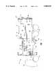
- FIG. 1is a side view of a truck body, parts of which have been removed to expose certain details including the receiving hoppers and packing apparatus and the ejection assist apparatus of the invention mounted in a multiple compartment side loading refuse vehicle body depicted in the loading or transporting position with the compacting and ejection mechanisms in the forward or retractable position;
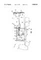
- FIG. 2depicts the truck body of FIG. 1 in the tilted or discharge position with respect to the upper storage compartment shown with the closure door open and the ejection mechanism of the invention extended;
- FIG. 3is a partial cross-sectional view taken along lines 3--3 of FIG. 1;
- FIG. 4is a view similar to that of FIG. 1 to illustrate the compacting mechanisms in the fully rearward or packing position;
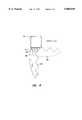
- FIG. 5is an enlarged exploded fragmentary perspective view of the ejection mechanism of the invention.
- FIG. 6is a greatly enlarged fragmentary view showing one possible tooth mounting system detail.
- the present inventioninvolves an ejection assist device or mechanism compatible with virtually any front or side loading, rear gravity discharging refuse truck not equipped with a full length or sweep ejector system.
- the ejector devicealleviates clogging of the refuse storage compartments thereby assuring complete discharge when emptied. It is particularly adapted to storage compartments associated with or charged by an enlarged or dropped floor charging hopper which may lead into a storage area of lesser cross section than the adjacent charging hopper compartment which thereby creates a necked-down passage beyond the range of the packing ram which, once clogged, will resist gravity discharge when the truck body is tipped to be emptied.
- a refuse truckis shown generally at 10 that includes a cab section 12 and a truck body 14 with integral charging hopper 16 and storage area 18 all mounted on a truck chassis 20 carried by a plurality of wheels 22.
- the truck body 14is pivotally mounted on the chassis 20 at 24 (FIG. 2) so as to be tipped or raised to discharge materials as by a pair of telescoping cylinders, one of which is shown at 26 pivotally mounted to the chassis at 28.
- the charging or loading hopper 16has a top (not shown) which opens for loading in coordination with the raising of a side loading bucket or container tipper in a well-known manner, the charging hopper is generally divided into upper and lower charging compartments or areas 30 and 32, respectively, which, in turn, connect with respective upper and lower storage volumes or compartments 34 and 36, separation being maintained by a partition or knee wall at 38 and a full width dividing floor 42, ramped at 40, which extends from the charging area through the storage area.
- the ramp 40creates a transition between the lowered floor of the upper charging hopper and the rearward or final upper storage volume.
- An upper packing systemis shown at 46 with packing panel 48 and upper follower 49 and a lower packing system at 50 with follower panel 51 and packing panel 52.
- the charging hopperis recessed at 70 so that the side loading mechanism may be accommodated next to the charging hopper without extending beyond the width of the truck at 72 when in a stowed position.
- Each packer system 46 and 50preferably rides on a friction reducing wear surface system including bottom rails or tracks, guide shoes and wear pads which direct and align the panel as it is displaced between the stowed and packing positions. These are shown as at 74 in FIG. 3. A complete description of such as system including the guide shoes and wear pads suitable for use with the present invention is shown and described in U.S. application Ser. No. 08/717,485, filed on Sep.
- wear shoes and/or wear padscan be made of any suitable self-lubricating polymer or a modified polymer material or of conventional materials including steel, bronze, brass or any combination thereof.
- FIG. 1depicts the upper and lower packing systems 46 and 50 and the ejector system of the invention in the fully forward positions ready for receiving materials to be dumped into the charging hopper 16.
- FIG. 4depicts the system with the compactor panels in the fully rearward or packing position. Note that the upper panel 48 extends only a very short distance into the storage volume 34, a distance shy of the beginning of the upward ramp 40 at 49. In this manner, material is sequentially, systematically and completely packed rearward but the ramp area of reduced cross section is not fully cleared, i.e., there is material compacted before and along the ramp area. This may later result in clogging and failure to fully discharge the load when the truck body is tilted for gravity induced dumping.
- the ejection assisting system of the present inventionwhich operates reciprocally along an axis parallel to that of the longitudinal axis of the vehicle and truck body to clear the vicinity of the ramp of any residual materials during the dumping operation.
- the ejection system of the inventionincludes a main or outer tubular member 80 which houses a double-acting hydraulic or other fluid operated cylinder 82 which reciprocally moves an inner tube 84 which is connected at right angles to a rakehead or ejector head 86 which may carry a plurality of deflectable tines or teeth 88.
- the inner tube 84reciprocally telescopes within the outertube 80 using a plurality of sets of friction-reducing wear shoes as at 90 and 92 which may be bolted to the outside of the member 84 or the inside of the member 80 in a well-known manner to ease the reciprocation of the inner tube 84 as it rides in the outer tube 80.
- the wear shoescan be made of any suitable self-lubricating polymer or a modified polymer or of any conventional materials including steel, bronze, brass or any combination thereof.
- the cylinderis fastened inside and between the tubes 80 and 84 at 94 and 96 as by using pins as at 98 and 100, respectively, in conjunction with pivotal collars 102 and 104 connected respectively to the cylinder and rod ends of the cylinder 82.
- the teethare mounted to rake segment 94 as by a lug 106 in a manner such that the rake teeth 88 may pivot up and out of the way during the return stroke of the ejection mechanism in which the system is retracted but will remain fully extended or deployed during the power or ejection stroke of the ejection assisting system of the invention.
- the teethmay be spring loaded or provided with a cam as at 108 in FIG. 6 which limits its travel by being forced against the side 110 of the tube 94 when the tooth is fully deployed as shown in FIG. 6.
- the tooth 88is shown in both positions in FIG. 6, the retracted or folded position being shown in the dash lines.
- the ejection system of the inventionnormally remains in the fully retracted position as depicted in FIGS. 1, 2 and 4 with the cylinder 82 fully retracted and the inner tube 84 retracted into the outer tube 80. Illustrated in FIG. 2, the system is normally activated only in conjunction with discharge or the dumping of the load.
- the systemis shown fully extended with the rake end 86 extending well into the upper storage area 34 thereby clearing the vicinity of the ramped floor section at 40.
- the systemcan be repeatedly reciprocally stroked as necessary to fully clear the load from the upper storage area 34 obviating any clogging that might occur due to the reduction in cross sectional area caused by the ramp 40. In this manner, the volume 34 can be readily cleared when it is desired to dump the load.
- the lower storage section 36enlarges toward the rear of the truck and the ejection assist device generally need not be used in such a situation.
Landscapes
- Engineering & Computer Science (AREA)
- Mechanical Engineering (AREA)
- Refuse-Collection Vehicles (AREA)
Abstract
Description
Claims (9)
Priority Applications (1)
| Application Number | Priority Date | Filing Date | Title |
|---|---|---|---|
| US08/902,667US5885049A (en) | 1997-07-30 | 1997-07-30 | Ejection mechanism for refuse trucks |
Applications Claiming Priority (1)
| Application Number | Priority Date | Filing Date | Title |
|---|---|---|---|
| US08/902,667US5885049A (en) | 1997-07-30 | 1997-07-30 | Ejection mechanism for refuse trucks |
Publications (1)
| Publication Number | Publication Date |
|---|---|
| US5885049Atrue US5885049A (en) | 1999-03-23 |
Family
ID=25416205
Family Applications (1)
| Application Number | Title | Priority Date | Filing Date |
|---|---|---|---|
| US08/902,667Expired - Fee RelatedUS5885049A (en) | 1997-07-30 | 1997-07-30 | Ejection mechanism for refuse trucks |
Country Status (1)
| Country | Link |
|---|---|
| US (1) | US5885049A (en) |
Cited By (25)
| Publication number | Priority date | Publication date | Assignee | Title |
|---|---|---|---|---|
| US6146078A (en)* | 1996-03-25 | 2000-11-14 | Pak-Mor Manufacturing Company | Refuse body having single-stage packing and full ejection |
| US20030223849A1 (en)* | 2002-02-25 | 2003-12-04 | Hagenbuch Leroy G. | Rear eject body for off-highway haulage units |
| US20040184904A1 (en)* | 2003-03-21 | 2004-09-23 | Fanotech Enviro Inc. | Multiple compartment waste collection container |
| US20050126569A1 (en)* | 2002-05-10 | 2005-06-16 | Crowder Timothy M. | Dry powder inhalers, related blister devices, and associated methods of dispensing dry powder substances and fabricating blister packages |
| US20080067856A1 (en)* | 2006-09-14 | 2008-03-20 | Hagenbuch Leroy G | Severe application off-highway truck body |
| US20080232423A1 (en)* | 2007-03-21 | 2008-09-25 | Edw. C. Levy Co. | Method, System and Process for Preparing a Recyclable Material |
| US20080298941A1 (en)* | 2003-02-25 | 2008-12-04 | Hagenbuch Leroy G | Charge Bucket Loading for Electric ARC Furnace Production |
| US20130239827A1 (en)* | 2012-03-15 | 2013-09-19 | Arthur Baird Zimmerman | System and apparatus for mounting hydraulic cylinder to packer panel of refuse truck |
| US20150047516A1 (en)* | 2013-08-16 | 2015-02-19 | Richard T. Williams | Method and delivery of compacting materials |
| US20160318722A1 (en)* | 2015-04-29 | 2016-11-03 | Gary Cervelli | Three-compartment vehicle |
| CN108001918A (en)* | 2017-12-28 | 2018-05-08 | 山东五征集团有限公司 | Can be classified loading and unloading type Dumpcart wagon |
| CN108792376A (en)* | 2018-07-11 | 2018-11-13 | 杨益鹏 | A kind of Clean- garbage truck of municipal administration environmental sanitation |
| US10525648B2 (en)* | 2013-08-16 | 2020-01-07 | Richard T. Williams | Method and device for compacting materials |
| US10843379B2 (en) | 2017-09-25 | 2020-11-24 | Oshkosh Corporation | Mixing drum |
| US11376990B1 (en) | 2021-08-13 | 2022-07-05 | Oshkosh Defense, Llc | Electrified military vehicle |
| US11498409B1 (en) | 2021-08-13 | 2022-11-15 | Oshkosh Defense, Llc | Electrified military vehicle |
| US12030479B1 (en) | 2021-08-13 | 2024-07-09 | Oshkosh Defense, Llc | Prioritized charging of an energy storage system of a military vehicle |
| US12060053B1 (en) | 2021-08-13 | 2024-08-13 | Oshkosh Defense, Llc | Military vehicle with control modes |
| US12083995B1 (en) | 2021-08-13 | 2024-09-10 | Oshkosh Defense, Llc | Power export system for a military vehicle |
| US12130122B1 (en) | 2021-08-13 | 2024-10-29 | Oshkosh Defense, Llc | Military vehicle with battery armor |
| US12311754B1 (en) | 2021-08-13 | 2025-05-27 | Oshkosh Defense, Llc | Power export system for a military vehicle |
| US12319160B1 (en) | 2021-08-13 | 2025-06-03 | Oshkosh Defense, Llc | Convoy operations for electrified military vehicles |
| US12351028B1 (en) | 2021-08-13 | 2025-07-08 | Oshkosh Defense, Llc | Military vehicle with modular battery units |
| US12358361B1 (en) | 2021-08-13 | 2025-07-15 | Oshkosh Defense, Llc | Electrified military vehicle with electric weaponry support system |
| US12441177B1 (en) | 2024-03-11 | 2025-10-14 | Oshkosh Defense, Llc | Electrified military vehicle |
Citations (13)
| Publication number | Priority date | Publication date | Assignee | Title |
|---|---|---|---|---|
| US3211309A (en)* | 1963-03-20 | 1965-10-12 | Peter S Shubin | Rubbish collecting vehicle with loading and packing apparatus |
| DE2262288A1 (en)* | 1972-12-20 | 1974-06-27 | Sollinger Huette | CONTAINER TO RECEIVE MUELL FACTORY REMAINS AND THE like |
| US4264261A (en)* | 1978-08-09 | 1981-04-28 | Lodal, Inc. | Refuse collection with platen stroke extension |
| US4271756A (en)* | 1979-12-18 | 1981-06-09 | Blackwelders | Load retraction preventing finger array |
| GB2137955A (en)* | 1983-03-16 | 1984-10-17 | Saphem | Compacting device |
| US4544320A (en)* | 1983-07-25 | 1985-10-01 | Haines Allan B | Refuse container |
| DE3447814A1 (en)* | 1984-12-29 | 1986-07-03 | geb. Oswald Renate 7121 Erligheim Würtz | Discharging apparatus for a refuse collection vehicle |
| CA1239977A (en)* | 1984-09-28 | 1988-08-02 | George J. English | Automobile headlight with combined heat and light shield |
| WO1991004206A1 (en)* | 1989-09-22 | 1991-04-04 | Landsdorff Stig Ragnar Johann | Torque-loaded door for a piston compactor |
| US5316430A (en)* | 1989-08-04 | 1994-05-31 | Galion Holding Company | Material collecting and hauling apparatus |
| US5484246A (en)* | 1989-08-04 | 1996-01-16 | Galion Holding Company | Collecting, hauling and delivering apparatus for recyclable materials |
| US5740726A (en)* | 1994-12-21 | 1998-04-21 | Schwelling; Hermann | Waste material press with distance ledges and retaining claws |
| US5785487A (en)* | 1997-01-27 | 1998-07-28 | Mcneilus Truck And Manufacturing, Inc. | Push out ejection systems for refuse truck |
- 1997
- 1997-07-30USUS08/902,667patent/US5885049A/ennot_activeExpired - Fee Related
Patent Citations (13)
| Publication number | Priority date | Publication date | Assignee | Title |
|---|---|---|---|---|
| US3211309A (en)* | 1963-03-20 | 1965-10-12 | Peter S Shubin | Rubbish collecting vehicle with loading and packing apparatus |
| DE2262288A1 (en)* | 1972-12-20 | 1974-06-27 | Sollinger Huette | CONTAINER TO RECEIVE MUELL FACTORY REMAINS AND THE like |
| US4264261A (en)* | 1978-08-09 | 1981-04-28 | Lodal, Inc. | Refuse collection with platen stroke extension |
| US4271756A (en)* | 1979-12-18 | 1981-06-09 | Blackwelders | Load retraction preventing finger array |
| GB2137955A (en)* | 1983-03-16 | 1984-10-17 | Saphem | Compacting device |
| US4544320A (en)* | 1983-07-25 | 1985-10-01 | Haines Allan B | Refuse container |
| CA1239977A (en)* | 1984-09-28 | 1988-08-02 | George J. English | Automobile headlight with combined heat and light shield |
| DE3447814A1 (en)* | 1984-12-29 | 1986-07-03 | geb. Oswald Renate 7121 Erligheim Würtz | Discharging apparatus for a refuse collection vehicle |
| US5316430A (en)* | 1989-08-04 | 1994-05-31 | Galion Holding Company | Material collecting and hauling apparatus |
| US5484246A (en)* | 1989-08-04 | 1996-01-16 | Galion Holding Company | Collecting, hauling and delivering apparatus for recyclable materials |
| WO1991004206A1 (en)* | 1989-09-22 | 1991-04-04 | Landsdorff Stig Ragnar Johann | Torque-loaded door for a piston compactor |
| US5740726A (en)* | 1994-12-21 | 1998-04-21 | Schwelling; Hermann | Waste material press with distance ledges and retaining claws |
| US5785487A (en)* | 1997-01-27 | 1998-07-28 | Mcneilus Truck And Manufacturing, Inc. | Push out ejection systems for refuse truck |
Cited By (62)
| Publication number | Priority date | Publication date | Assignee | Title |
|---|---|---|---|---|
| US6146078A (en)* | 1996-03-25 | 2000-11-14 | Pak-Mor Manufacturing Company | Refuse body having single-stage packing and full ejection |
| US20030223849A1 (en)* | 2002-02-25 | 2003-12-04 | Hagenbuch Leroy G. | Rear eject body for off-highway haulage units |
| WO2003072392A3 (en)* | 2002-02-25 | 2004-04-22 | Hagenbuch Roy George Le | Rear eject body for off-highway haulage units |
| US7878751B2 (en) | 2002-02-25 | 2011-02-01 | Hagenbuch Leroy G | Rear eject body for off-highway haulage units |
| EP1487664A4 (en)* | 2002-02-25 | 2005-09-14 | Hagenbuch Roy George Le | Rear eject body for off-highway haulage units |
| US7326023B2 (en) | 2002-02-25 | 2008-02-05 | Hagenbuch Leroy G | Rear eject body for off-highway haulage units |
| JP2009107625A (en)* | 2002-02-25 | 2009-05-21 | Leroy G Hagenbuch | Rear ejection body for transporting device outside public road |
| US20080145200A1 (en)* | 2002-02-25 | 2008-06-19 | Hagenbuch Leroy G | Rear eject body for off-highway haulage units |
| US20050126569A1 (en)* | 2002-05-10 | 2005-06-16 | Crowder Timothy M. | Dry powder inhalers, related blister devices, and associated methods of dispensing dry powder substances and fabricating blister packages |
| US20080298941A1 (en)* | 2003-02-25 | 2008-12-04 | Hagenbuch Leroy G | Charge Bucket Loading for Electric ARC Furnace Production |
| US7118320B2 (en) | 2003-03-21 | 2006-10-10 | Fanotech Enviro Inc. | Multiple compartment waste collection container |
| US20040184904A1 (en)* | 2003-03-21 | 2004-09-23 | Fanotech Enviro Inc. | Multiple compartment waste collection container |
| US20080067856A1 (en)* | 2006-09-14 | 2008-03-20 | Hagenbuch Leroy G | Severe application off-highway truck body |
| US7901009B2 (en) | 2006-09-14 | 2011-03-08 | Hagenbuch Leroy G | Severe application off-highway truck body |
| US20080232423A1 (en)* | 2007-03-21 | 2008-09-25 | Edw. C. Levy Co. | Method, System and Process for Preparing a Recyclable Material |
| US8702367B2 (en) | 2007-03-21 | 2014-04-22 | Edw. C. Levy Co. | Method, and process for preparing a recyclable material |
| US20130239827A1 (en)* | 2012-03-15 | 2013-09-19 | Arthur Baird Zimmerman | System and apparatus for mounting hydraulic cylinder to packer panel of refuse truck |
| US20150047516A1 (en)* | 2013-08-16 | 2015-02-19 | Richard T. Williams | Method and delivery of compacting materials |
| US10421243B2 (en)* | 2013-08-16 | 2019-09-24 | Richard T. Williams | Method and delivery of compacting materials |
| US10525648B2 (en)* | 2013-08-16 | 2020-01-07 | Richard T. Williams | Method and device for compacting materials |
| US20160318722A1 (en)* | 2015-04-29 | 2016-11-03 | Gary Cervelli | Three-compartment vehicle |
| US10843379B2 (en) | 2017-09-25 | 2020-11-24 | Oshkosh Corporation | Mixing drum |
| US11999078B2 (en) | 2017-09-25 | 2024-06-04 | Oshkosh Corporation | Mixing drum |
| CN108001918A (en)* | 2017-12-28 | 2018-05-08 | 山东五征集团有限公司 | Can be classified loading and unloading type Dumpcart wagon |
| CN108001918B (en)* | 2017-12-28 | 2023-10-20 | 山东五征集团有限公司 | Garbage truck carriage capable of being assembled and disassembled in classified mode |
| CN108792376A (en)* | 2018-07-11 | 2018-11-13 | 杨益鹏 | A kind of Clean- garbage truck of municipal administration environmental sanitation |
| US11485228B1 (en) | 2021-08-13 | 2022-11-01 | Oshkosh Defense, Llc | Electrified military vehicle |
| US11987128B2 (en) | 2021-08-13 | 2024-05-21 | Oshkosh Defense, Llc | Electrified military vehicle |
| US11383694B1 (en) | 2021-08-13 | 2022-07-12 | Oshkosh Defense, Llc | Electrified military vehicle |
| US11465486B1 (en) | 2021-08-13 | 2022-10-11 | Oshkosh Defense, Llc | Electrified military vehicle |
| US11377089B1 (en) | 2021-08-13 | 2022-07-05 | Oshkosh Defense, Llc | Electrified military vehicle |
| US11498409B1 (en) | 2021-08-13 | 2022-11-15 | Oshkosh Defense, Llc | Electrified military vehicle |
| US11505062B1 (en) | 2021-08-13 | 2022-11-22 | Oshkosh Defense, Llc | Electrified military vehicle |
| US11511613B1 (en) | 2021-08-13 | 2022-11-29 | Oshkosh Defense, Llc | Electrified military vehicle |
| US11597399B1 (en) | 2021-08-13 | 2023-03-07 | Oshkosh Defense, Llc | Electrified military vehicle |
| US11608050B1 (en) | 2021-08-13 | 2023-03-21 | Oshkosh Defense, Llc | Electrified military vehicle |
| US11607946B2 (en) | 2021-08-13 | 2023-03-21 | Oshkosh Defense, Llc | Electrified military vehicle |
| US11697338B2 (en) | 2021-08-13 | 2023-07-11 | Oshkosh Defense, Llc | Electrified military vehicle |
| US11376958B1 (en) | 2021-08-13 | 2022-07-05 | Oshkosh Defense, Llc | Electrified military vehicle |
| US11865921B2 (en) | 2021-08-13 | 2024-01-09 | Oshkosh Defense, Llc | Electrified military vehicle |
| US11890940B2 (en) | 2021-08-13 | 2024-02-06 | Oshkosh Defense, Llc | Electrified military vehicle |
| US11958361B2 (en) | 2021-08-13 | 2024-04-16 | Oshkosh Defense, Llc | Electrified military vehicle |
| US11981340B1 (en) | 2021-08-13 | 2024-05-14 | Oshkosh Defense, Llc | Electrified military vehicle |
| US11376943B1 (en) | 2021-08-13 | 2022-07-05 | Oshkosh Defense, Llc | Electrified military vehicle |
| US11993152B2 (en) | 2021-08-13 | 2024-05-28 | Oshkosh Defense, Llc | Electrified military vehicle |
| US11376990B1 (en) | 2021-08-13 | 2022-07-05 | Oshkosh Defense, Llc | Electrified military vehicle |
| US12005783B2 (en) | 2021-08-13 | 2024-06-11 | Oshkosh Defense, Llc | Electrified military vehicle |
| US12030479B1 (en) | 2021-08-13 | 2024-07-09 | Oshkosh Defense, Llc | Prioritized charging of an energy storage system of a military vehicle |
| US12060053B1 (en) | 2021-08-13 | 2024-08-13 | Oshkosh Defense, Llc | Military vehicle with control modes |
| US12083995B1 (en) | 2021-08-13 | 2024-09-10 | Oshkosh Defense, Llc | Power export system for a military vehicle |
| US12090856B2 (en) | 2021-08-13 | 2024-09-17 | Oshkosh Defense, Llc | Electrified military vehicle |
| US12130122B1 (en) | 2021-08-13 | 2024-10-29 | Oshkosh Defense, Llc | Military vehicle with battery armor |
| US12179599B2 (en) | 2021-08-13 | 2024-12-31 | Oshkosh Defense, Llc | Electrified military vehicle |
| US12179598B2 (en) | 2021-08-13 | 2024-12-31 | Oshkosh Defense, Llc | Electrified military vehicle |
| US12252017B1 (en) | 2021-08-13 | 2025-03-18 | Oshkosh Defense, Llc | Electrified military vehicle |
| US12311754B1 (en) | 2021-08-13 | 2025-05-27 | Oshkosh Defense, Llc | Power export system for a military vehicle |
| US12319160B1 (en) | 2021-08-13 | 2025-06-03 | Oshkosh Defense, Llc | Convoy operations for electrified military vehicles |
| US12351028B1 (en) | 2021-08-13 | 2025-07-08 | Oshkosh Defense, Llc | Military vehicle with modular battery units |
| US12358361B1 (en) | 2021-08-13 | 2025-07-15 | Oshkosh Defense, Llc | Electrified military vehicle with electric weaponry support system |
| US12365234B1 (en) | 2021-08-13 | 2025-07-22 | Oshkosh Defense, Llc | Electrified military vehicle |
| US12427847B1 (en) | 2021-08-13 | 2025-09-30 | Oshkosh Defense, Llc | Electrified military vehicle |
| US12441177B1 (en) | 2024-03-11 | 2025-10-14 | Oshkosh Defense, Llc | Electrified military vehicle |
Similar Documents
| Publication | Publication Date | Title |
|---|---|---|
| US5885049A (en) | Ejection mechanism for refuse trucks | |
| US7070382B2 (en) | Full eject manual/automated side loader | |
| US5857822A (en) | Ejection and compacting system for refuse truck | |
| US6210094B1 (en) | Refuse collection system | |
| US7284943B2 (en) | Full eject manual/automated side loader | |
| US6146078A (en) | Refuse body having single-stage packing and full ejection | |
| US5931628A (en) | Manual/automated side loader | |
| US5813818A (en) | Multi-compartment side bucket refuse collection system | |
| CA2143852C (en) | Apparatus for packing separated recyclable materials | |
| US4923356A (en) | Apparatus for collecting and compacting garbage and then loading it into a road vehicle | |
| US5785487A (en) | Push out ejection systems for refuse truck | |
| US20090067965A1 (en) | Side-loading refuse collection apparatus and method | |
| DE3537546A1 (en) | Multi-chamber waste collection vehicle | |
| US4316695A (en) | Garbage compaction truck | |
| US5868543A (en) | Drop floor split body charging hopper system having a dual linear packing system | |
| US7086818B2 (en) | Full-eject automated side/front loading collection vehicle | |
| US3955694A (en) | Side loading refuse body | |
| CA1252760A (en) | Vehicle for transporting garbage or the like | |
| US20040071537A1 (en) | Refuse packer with retractable loading hopper | |
| US11518612B2 (en) | Multi-compartment refuse collecting truck body and control system | |
| US5176488A (en) | Combination rear loading compactor and recycler | |
| US20150047516A1 (en) | Method and delivery of compacting materials | |
| US10525648B2 (en) | Method and device for compacting materials | |
| US3771675A (en) | Refuse collecting vehicle | |
| CA2533768C (en) | Full eject manual/automated side loader |
Legal Events
| Date | Code | Title | Description |
|---|---|---|---|
| AS | Assignment | Owner name:MCNEILUS TRUCK AND MANUFACTURING, INC., MINNESOTA Free format text:ASSIGNMENT OF ASSIGNORS INTEREST;ASSIGNORS:MCNEILUS, GARWIN B.;HARRIS, WILBUR R.;REEL/FRAME:008973/0120 Effective date:19980216 | |
| AS | Assignment | Owner name:BANK OF AMERICA NATIONAL TRUST AND SAVINGS, ILLINO Free format text:SECURITY INTEREST;ASSIGNOR:MCNEILUS TRUCK & MANUFACTURING, INC.;REEL/FRAME:009350/0563 Effective date:19980226 | |
| AS | Assignment | Owner name:BANK OF AMERICA, N.A. AS AGENT., (F/N/A) BANK OF A Free format text:SECOND REAFFIRMATION AND AMENDMENT AGREEMENT;ASSIGNOR:MCNEILUS TRUCK AND MANUFACTURING INC.;REEL/FRAME:012153/0539 Effective date:20010723 | |
| FEPP | Fee payment procedure | Free format text:PAYOR NUMBER ASSIGNED (ORIGINAL EVENT CODE: ASPN); ENTITY STATUS OF PATENT OWNER: LARGE ENTITY | |
| FPAY | Fee payment | Year of fee payment:4 | |
| AS | Assignment | Owner name:MCNEILUS TRUCK AND MANUFACTURING, INC., MINNESOTA Free format text:RELEASE OF SECURITY INTEREST RECORDED UNDER REEL AND FRAME 009350/0563;ASSIGNOR:BANK OF AMERICA N.A. (F/K/A BANK OF AMERICA NATIONAL TRUST AND SAVINGS ASSOCIATION);REEL/FRAME:015209/0775 Effective date:20040929 Owner name:MCNEILUS TRUCK AND MANUFACTURING, INC., MINNESOTA Free format text:RELEASE OF SECURITY INTEREST RECORDED UNDER REEL AND FRAME 012153/0539;ASSIGNOR:BANK OF AMERICA N.A. (F/K/A BANK OF AMERICA NATIONAL TRUST AND SAVINGS ASSOCIATION);REEL/FRAME:015209/0783 Effective date:20040929 | |
| REMI | Maintenance fee reminder mailed | ||
| LAPS | Lapse for failure to pay maintenance fees | ||
| STCH | Information on status: patent discontinuation | Free format text:PATENT EXPIRED DUE TO NONPAYMENT OF MAINTENANCE FEES UNDER 37 CFR 1.362 | |
| FP | Lapsed due to failure to pay maintenance fee | Effective date:20070328 |