US5884872A - Oscillating flap lift enhancement device - Google Patents
Oscillating flap lift enhancement deviceDownload PDFInfo
- Publication number
- US5884872A US5884872AUS08/528,622US52862295AUS5884872AUS 5884872 AUS5884872 AUS 5884872AUS 52862295 AUS52862295 AUS 52862295AUS 5884872 AUS5884872 AUS 5884872A
- Authority
- US
- United States
- Prior art keywords
- flap
- wing
- degrees
- oscillating
- oscillates
- Prior art date
- Legal status (The legal status is an assumption and is not a legal conclusion. Google has not performed a legal analysis and makes no representation as to the accuracy of the status listed.)
- Expired - Fee Related
Links
- 238000000034methodMethods0.000claimsdescription6
- 239000007787solidSubstances0.000abstractdescription6
- 230000007246mechanismEffects0.000abstractdescription4
- 230000002708enhancing effectEffects0.000abstract1
- 230000000694effectsEffects0.000description5
- 230000008901benefitEffects0.000description3
- 238000006073displacement reactionMethods0.000description3
- 238000004026adhesive bondingMethods0.000description2
- 230000006872improvementEffects0.000description2
- 230000008859changeEffects0.000description1
- 230000003111delayed effectEffects0.000description1
- 238000009795derivationMethods0.000description1
- 230000001066destructive effectEffects0.000description1
- 230000001627detrimental effectEffects0.000description1
- 239000000446fuelSubstances0.000description1
- 238000012986modificationMethods0.000description1
- 230000004048modificationEffects0.000description1
- 230000008520organizationEffects0.000description1
- 230000010355oscillationEffects0.000description1
- 238000000926separation methodMethods0.000description1
- 230000003068static effectEffects0.000description1
Images


Classifications
- B—PERFORMING OPERATIONS; TRANSPORTING
- B64—AIRCRAFT; AVIATION; COSMONAUTICS
- B64C—AEROPLANES; HELICOPTERS
- B64C9/00—Adjustable control surfaces or members, e.g. rudders
- B64C9/30—Balancing hinged surfaces, e.g. dynamically
- B—PERFORMING OPERATIONS; TRANSPORTING
- B64—AIRCRAFT; AVIATION; COSMONAUTICS
- B64C—AEROPLANES; HELICOPTERS
- B64C9/00—Adjustable control surfaces or members, e.g. rudders
- B64C9/02—Mounting or supporting thereof
- Y—GENERAL TAGGING OF NEW TECHNOLOGICAL DEVELOPMENTS; GENERAL TAGGING OF CROSS-SECTIONAL TECHNOLOGIES SPANNING OVER SEVERAL SECTIONS OF THE IPC; TECHNICAL SUBJECTS COVERED BY FORMER USPC CROSS-REFERENCE ART COLLECTIONS [XRACs] AND DIGESTS
- Y02—TECHNOLOGIES OR APPLICATIONS FOR MITIGATION OR ADAPTATION AGAINST CLIMATE CHANGE
- Y02T—CLIMATE CHANGE MITIGATION TECHNOLOGIES RELATED TO TRANSPORTATION
- Y02T50/00—Aeronautics or air transport
- Y02T50/30—Wing lift efficiency
Definitions
- This inventionrelates to improved lifting capabilities of a solid wing that has a motor driven, flap mechanism that oscillates over a range of frequencies and over a range of angular deflections.
- the flapis a flat, single plate-like member having a length of between 0.5% to 1.50% of the chord of the airfoil and is fixedly positioned at a downward angle to the chord of between 5° and 25°.
- the length of the flapis approximately 1% of the chord and the preferred angle to the chord is 20°.
- a flapis rotatably connected to a wing and the flap is deflected in a purely static manner.
- the present inventionis a dynamically oscillating flap that produces an increase in the lifting capabilities of the wing. This increase in the lift is particularly effective at set frequencies and at predetermined angular deflections.
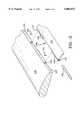
- FIG. 1shows a fragmentary perspective view of a solid wing with power means attached to drive a solid flap
- FIG. 2shows a fragmentary and expanded perspective view of the wing of FIG. 1, showing the means of attachment of the trailing edge flap to the wing;
- FIG. 3shows an isolated view of the connection of the power means of FIG. 1 to the solid rod
- FIG. 4shows a side view of the connection means of FIG. 3.
- FIG. 5shows the derivation of the modified reduced frequency equation
- FIG. 6is a plot of experimental data showing lift coefficient vs wing angle of attack.
- FIG. 7is a plot showing how the maximum lift coefficient increases as the Modified Reduced Frequency is increased.
- FIGS. 1 through 4show an embodiment of the oscillating wing.
- FIG. 1shows a partially broken-away, perspective view of a solid wing 120 having a mechanically driven flap 125 attached to oscillate about a hinge line.
- wing 120has a plurality of hinge tubes 131 fixed, as by gluing, to its trailing edge 127.
- Flap 125has a plurality of hinge tubes 132 fixed, as by gluing, to its leading edge 128 in such a spaced apart relationship such that when flap 125 is brought adjacent to the trailing edge of wing 120, hinge tubes 132 fit in-between tubes 131 to form a uniform centerline therein and accommodate drive rod 135.
- drive rod 135is connected to hinge tubes 132, and hence, to flap 125, through the use of tapered drive pins 137. After rod 135 is fitted into hinge tubes 131, 132, pins 137 are secured through openings 139 into rod 135.
- An electric motor 141is connected to drive rod 135 to supply power to the mechanism.
- a connecting link 143is, at one end, adjustably fixed, as at one of a plurality of locations 145, to crank plate 142, and, at the other end, to a lever 150.
- FIG. 3shows an enlarged, isolated view of lever 150 with one of side arms 151 broken away to show the bearings 152 at the pin joint 154.
- Screws 153allow flap 125 to be rotated or turned relative to the driving forces and therefore set with either a positive or negative bias.
- the drive rod 135is oscillated by the lever 150 and the set screws 153 allow the wing flap to be rotated or turned relative to the lever 150, hence the flap can be set with a positive or negative initial angular displacement as a general flap setting.
- a lead weight 155is set into the end of lever 150 to allow for the balancing of inertial forces of flap 125 and the connecting link 142 and also to account for the balancing of the inertia forces of some portion of the oscillating connecting rod mass 135.
- FIG. 5is an illustration of the definition of the Modified Reduced Frequency.
- the Modified Reduced Frequencyis a non-dimensional number that is calculated by dividing the product of the circular frequency " ⁇ " and the crossflow reference length "L” by twice the free stream air velocity "V.sub. ⁇ “.
- the circular frequency " ⁇ ”is equal to 2 ⁇ f where "f” is the flap oscillation frequency and “L” is twice the flap length "1,” multiplied by the "sine ⁇ ", and " ⁇ ” is the oscillating angular displacement.
- An alternative definition of the Modified Reduced Frequencyis also illustrated in FIG. 5.
- the Modified Reduced Frequencycan be expressed and calculated by taking the ratio of crossflow reference length "L” to the wave length " ⁇ ” multiplied by " ⁇ ".
- " ⁇ "is the wave length between the pairs of vortices that are shed at the trailing edge of the wing.
- FIG. 6is a plot of experimental data showing lift coefficient vs wing angle of attack showing the effects of oscillating the 14.4% chord flap +/-12 degrees over a frequency range of 0 to 60 hz. The figure shows that the present invention provides a large lift enhancement in the +10 to -20 angle-of-attack range.
- the plot in FIG. 7shows how the maximum lift coefficient increases as the so called Modified Reduced Frequency is increased.
- An increase in the lift coeffecientis shown for all values of the modified reduced frequency from 0.04 to 0.048. There is a lift increase of 54% for a modified reduced frequency of 0.048.
Landscapes
- Engineering & Computer Science (AREA)
- Aviation & Aerospace Engineering (AREA)
- Toys (AREA)
Abstract
Description
The invention described herein may be manufactured and used by or for the Government of the United States of America for governmental purposes without the payment of any royalties thereon or therefor.
This is a continuation-in-part of U.S. application Ser. No. 08/245,083 filed on May 17, 1994, now abandoned which in turn is a division of U.S. Ser. No. 67,763 filed May 26, 1993 now U.S. Pat. No. 5,335,886 issued Aug. 9, 1994.
This invention relates to improved lifting capabilities of a solid wing that has a motor driven, flap mechanism that oscillates over a range of frequencies and over a range of angular deflections.
Over the past few years, there has been a great deal of interest in unsteady aerodynamics in several areas of air vehicle research from fighter aircraft to missile dynamics. Generally, the research falls into two basic categories: unsteady effects that produce destructive vibrational effects with detrimental stability and control, and those effects that may be used in a positive way. Aerodynamic research involving wings and airfoils continues to search for ways to improve the lifting characteristics of airfoils by whatever means for purposes of improved flight parameters, larger payload capability or better handling characteristics at predetermined velocities. Towards this end, U.S. Pat. No. 4,867,396 to Barnaby S. Wainfan, issued on Sep. 19, 1989, and assigned to the Lockheed Corporation discloses that it is known to fixedly attach a small flap-like device to the trailing edge of an airfoil to improve the coefficient of lift and reduce the coefficient of drag. The flap is a flat, single plate-like member having a length of between 0.5% to 1.50% of the chord of the airfoil and is fixedly positioned at a downward angle to the chord of between 5° and 25°. Preferably, the length of the flap is approximately 1% of the chord and the preferred angle to the chord is 20°. It has been found that the above change in the aerodynamic characteristics provides an overall increase in fuel efficiency. However, this improvement still falls short of providing the dramatic improvement in lift characteristics that is obtained by the present invention.
Also in Arena, U.S. Pat. No. 5,098,043, a flap is rotatably connected to a wing and the flap is deflected in a purely static manner. The present invention is a dynamically oscillating flap that produces an increase in the lifting capabilities of the wing. This increase in the lift is particularly effective at set frequencies and at predetermined angular deflections.
It is therefore an object of the present invention to improve the lifting capabilities of a wing;
It is a further object of the present invention to improve the lifting capabilities of a wing at high angles of attack;
It is a still further object of the present invention to improve the lifting capabilities of a wing over the normal operating range of angles of attack from -10 to +20 degrees and to allow the wing to produce a boost in the lift in the +10 to +20 degrees angle of attack.
These and other objects and many attendant advantages of the present invention are obtained where a motor driven, flap mechanism, oscillates at a set of frequencies and at a predetermined angular deflection.
The novel features which are believed to be characteristics of the invention, both as to its organization and methods of operation, together with further objects and advantages thereof, will be better understood from the following descriptions in connection with the accompanying drawings in which the presently preferred embodiments of the invention are illustrated by way of examples. It is to be expressly understood, however, that the drawings are for purposes of illustration and description only and are not intended as a definition of the limits of the invention.
FIG. 1 shows a fragmentary perspective view of a solid wing with power means attached to drive a solid flap;
FIG. 2 shows a fragmentary and expanded perspective view of the wing of FIG. 1, showing the means of attachment of the trailing edge flap to the wing;
FIG. 3 shows an isolated view of the connection of the power means of FIG. 1 to the solid rod; and
FIG. 4 shows a side view of the connection means of FIG. 3.
FIG. 5 shows the derivation of the modified reduced frequency equation
FIG. 6 is a plot of experimental data showing lift coefficient vs wing angle of attack.
FIG. 7 is a plot showing how the maximum lift coefficient increases as the Modified Reduced Frequency is increased.
FIGS. 1 through 4 show an embodiment of the oscillating wing. FIG. 1 shows a partially broken-away, perspective view of asolid wing 120 having a mechanically drivenflap 125 attached to oscillate about a hinge line. As seen in FIG. 2,wing 120 has a plurality ofhinge tubes 131 fixed, as by gluing, to itstrailing edge 127.Flap 125 has a plurality ofhinge tubes 132 fixed, as by gluing, to its leadingedge 128 in such a spaced apart relationship such that whenflap 125 is brought adjacent to the trailing edge ofwing 120,hinge tubes 132 fit in-betweentubes 131 to form a uniform centerline therein and accommodatedrive rod 135. As shown in FIG. 2,drive rod 135 is connected tohinge tubes 132, and hence, to flap 125, through the use oftapered drive pins 137. Afterrod 135 is fitted intohinge tubes pins 137 are secured throughopenings 139 intorod 135.
Anelectric motor 141 is connected to driverod 135 to supply power to the mechanism. A connectinglink 143 is, at one end, adjustably fixed, as at one of a plurality oflocations 145, tocrank plate 142, and, at the other end, to alever 150. FIG. 3 shows an enlarged, isolated view oflever 150 with one ofside arms 151 broken away to show thebearings 152 at thepin joint 154. By changing the radial location or position at the lower end of connectinglink 143 relative to the center of rotation ofcrank plate 142, the displacement angle offlap 125 can be varied (see FIG. 4). In FIG. 3, it can be seen that twoset screws 153 are used to fix the position oflever 150 relative to driverod 135.Screws 153 allowflap 125 to be rotated or turned relative to the driving forces and therefore set with either a positive or negative bias. Thedrive rod 135 is oscillated by thelever 150 and theset screws 153 allow the wing flap to be rotated or turned relative to thelever 150, hence the flap can be set with a positive or negative initial angular displacement as a general flap setting. Additionally, alead weight 155 is set into the end oflever 150 to allow for the balancing of inertial forces offlap 125 and the connectinglink 142 and also to account for the balancing of the inertia forces of some portion of the oscillatingconnecting rod mass 135.
The physics of the phenomena is as follows. Without the oscillating flap, the upper surface boundary layer of the wing separates at an angle of attack of about 10 degrees. With the oscillating flap the separated upper surface boundary layer becomes reattached or, in other words, with the oscillating flap turned on, boundary layer separation is delayed. This reattachment of the boundary layer produces up to a 54% increase in maximum lift and increases the angle at which the maximum lift occurs by up to eight degrees. It should be noted that both of these effects would be of great importance for the modem fighter aircraft where high angle of attack maneuverability gives an aircraft a great advantage over an opponent in a close combat situation.
FIG. 5 is an illustration of the definition of the Modified Reduced Frequency. The Modified Reduced Frequency is a non-dimensional number that is calculated by dividing the product of the circular frequency "ω" and the crossflow reference length "L" by twice the free stream air velocity "V.sub.∞ ". The circular frequency "ω" is equal to 2πf where "f" is the flap oscillation frequency and "L" is twice the flap length "1," multiplied by the "sine Δθ", and "Δθ" is the oscillating angular displacement. An alternative definition of the Modified Reduced Frequency is also illustrated in FIG. 5. The Modified Reduced Frequency can be expressed and calculated by taking the ratio of crossflow reference length "L" to the wave length "λ" multiplied by "π". "λ" is the wave length between the pairs of vortices that are shed at the trailing edge of the wing.
FIG. 6 is a plot of experimental data showing lift coefficient vs wing angle of attack showing the effects of oscillating the 14.4% chord flap +/-12 degrees over a frequency range of 0 to 60 hz. The figure shows that the present invention provides a large lift enhancement in the +10 to -20 angle-of-attack range.
The plot in FIG. 7 shows how the maximum lift coefficient increases as the so called Modified Reduced Frequency is increased. An increase in the lift coeffecient is shown for all values of the modified reduced frequency from 0.04 to 0.048. There is a lift increase of 54% for a modified reduced frequency of 0.048.
Finally, while the oscillating flapped wing has been described with reference to a particular embodiment, it should be understood that the embodiment is merely illustrative as there are numerous variations and modifications, such as shape and thickness of the flap, which may be made by those skilled in the art. Thus, the invention is to be construed as being limited only by the spirit and scope of the appended claims.
Claims (8)
1. An apparatus for increasing the lift of an aircraft comprising:
a) a wing having a leading edge and a trailing edge, the wing capable of providing lift;
b) a flap having a leading edge and a trailing edge, the leading edge of the flap pivotally attached to said trailing edge of said wing;
c) means for oscillating said flap; wherein said wing, said flap and said oscillating means communicate to maintain said flap in a predetermined stationary position at angles of attack less than 10 degrees and cause said flap to oscillate at angles of attack equal to or greater than 10 degrees.
2. The apparatus defined in claim 1, wherein said flap oscillates through an angle of up to +/-12 degrees.
3. The apparatus defined in claim 1, wherein said flap oscillates at a frequency of up to 70 hertz.
4. The apparatus defined in claim 1, wherein said flap oscillates through an angle of up to +/-12 degrees and at a frequency of up to 70 hertz.
5. A method for increasing the lift of an airfoil, the airfoil having a fixed forwardly portion for providing lift and a rearwardly portion for oscillating, the rearwardly portion pivotally attached to the forwardly portion, and also having means for oscillating said rearwardly portion, the method comprising the steps of:
a) maintaining said rearwardly portion in a fixed relationship with respect to said forwardly portion at angles of attack less than 10 degrees;
b) oscillating said rearwardly portion with respect to said forwardly portion at angles of attack equal to or greater than 10 degrees.
6. The method defined in claim 5, wherein said rearwardly portion oscillates at a frequency of up to 70 hertz.
7. The method defined in claim 5, wherein said rearwardly portion oscillates through an angle of up to +/-12 degrees.
8. The method defined in claim 5, wherein said rearwardly portion oscillates at a frequency of up to 70 hertz and oscillates through an angle of up to +/-12 degrees.
Priority Applications (1)
| Application Number | Priority Date | Filing Date | Title |
|---|---|---|---|
| US08/528,622US5884872A (en) | 1993-05-26 | 1995-08-30 | Oscillating flap lift enhancement device |
Applications Claiming Priority (3)
| Application Number | Priority Date | Filing Date | Title |
|---|---|---|---|
| US08/067,763US5335886A (en) | 1992-01-30 | 1993-05-26 | Lift enhancement device |
| US24508394A | 1994-05-17 | 1994-05-17 | |
| US08/528,622US5884872A (en) | 1993-05-26 | 1995-08-30 | Oscillating flap lift enhancement device |
Related Parent Applications (1)
| Application Number | Title | Priority Date | Filing Date |
|---|---|---|---|
| US24508394AContinuation-In-Part | 1993-05-26 | 1994-05-17 |
Publications (1)
| Publication Number | Publication Date |
|---|---|
| US5884872Atrue US5884872A (en) | 1999-03-23 |
Family
ID=26748230
Family Applications (1)
| Application Number | Title | Priority Date | Filing Date |
|---|---|---|---|
| US08/528,622Expired - Fee RelatedUS5884872A (en) | 1993-05-26 | 1995-08-30 | Oscillating flap lift enhancement device |
Country Status (1)
| Country | Link |
|---|---|
| US (1) | US5884872A (en) |
Cited By (59)
| Publication number | Priority date | Publication date | Assignee | Title |
|---|---|---|---|---|
| US6152692A (en)* | 1997-11-07 | 2000-11-28 | Eurocopter | Rotor blade with swivelling air flow control flap |
| US6224022B1 (en)* | 1999-02-26 | 2001-05-01 | Smiths Industries Actuation Systems Inc. | Airplane high lift surface drive system |
| WO2002046037A1 (en)* | 2000-12-05 | 2002-06-13 | Diversified Technologies, Inc. | Flap actuator system |
| US20030102410A1 (en)* | 2001-11-19 | 2003-06-05 | Andreas Gessler | Aerodynamic profile with an adjustable flap |
| US6641089B2 (en)* | 2001-09-27 | 2003-11-04 | Airbus Deutschland Gmbh | Flap arrangement for varying the aerodynamic lift generated by an aerodynamic element of an aircraft |
| US20030226933A1 (en)* | 2002-06-06 | 2003-12-11 | Charron Richard | Power assembly for ornicopter |
| US6672540B1 (en) | 2002-12-03 | 2004-01-06 | Rockwell Collins, Inc. | Actuator for aircraft stabilizers with a failure responsive lock control mechanism |
| US20060187528A1 (en)* | 2005-02-23 | 2006-08-24 | Pixtronix, Incorporated | Methods and apparatus for spatial light modulation |
| US20060187190A1 (en)* | 2005-02-23 | 2006-08-24 | Pixtronix, Incorporated | Display methods and apparatus |
| US20060187191A1 (en)* | 2005-02-23 | 2006-08-24 | Pixtronix, Incorporated | Display methods and apparatus |
| US20060187531A1 (en)* | 2005-02-23 | 2006-08-24 | Pixtronix, Incorporated | Methods and apparatus for bi-stable actuation of displays |
| US20060209012A1 (en)* | 2005-02-23 | 2006-09-21 | Pixtronix, Incorporated | Devices having MEMS displays |
| US20060250676A1 (en)* | 2005-02-23 | 2006-11-09 | Pixtronix, Incorporated | Light concentrating reflective display methods and apparatus |
| US20060256039A1 (en)* | 2005-02-23 | 2006-11-16 | Pixtronix, Incorporated | Display methods and apparatus |
| US7150434B1 (en)* | 2005-02-25 | 2006-12-19 | The United States Of America As Represented By The Secretary Of The Navy | Vehicle wake vortex modifier |
| US20070002156A1 (en)* | 2005-02-23 | 2007-01-04 | Pixtronix, Incorporated | Display apparatus and methods for manufacture thereof |
| US20070102588A1 (en)* | 2005-10-25 | 2007-05-10 | John Durant | Servo Mounting System for Direct Drive of an Aircraft Control Surface |
| US7271945B2 (en) | 2005-02-23 | 2007-09-18 | Pixtronix, Inc. | Methods and apparatus for actuating displays |
| US7304785B2 (en) | 2005-02-23 | 2007-12-04 | Pixtronix, Inc. | Display methods and apparatus |
| US20070279727A1 (en)* | 2006-06-05 | 2007-12-06 | Pixtronix, Inc. | Display apparatus with optical cavities |
| US20080201665A1 (en)* | 2007-02-15 | 2008-08-21 | Teac Corporation | Electronic equipment having plural function keys |
| US7502159B2 (en) | 2005-02-23 | 2009-03-10 | Pixtronix, Inc. | Methods and apparatus for actuating displays |
| US20090159755A1 (en)* | 2007-12-21 | 2009-06-25 | Airbus Espana, S.L. | Aircraft control device |
| US20090257245A1 (en)* | 2008-04-18 | 2009-10-15 | Pixtronix, Inc. | Light guides and backlight systems incorporating prismatic structures and light redirectors |
| US20090308981A1 (en)* | 2008-06-11 | 2009-12-17 | Airbus Uk Limited | Aircraft wing assembly |
| US7675665B2 (en) | 2005-02-23 | 2010-03-09 | Pixtronix, Incorporated | Methods and apparatus for actuating displays |
| US7746529B2 (en) | 2005-02-23 | 2010-06-29 | Pixtronix, Inc. | MEMS display apparatus |
| US7839356B2 (en) | 2005-02-23 | 2010-11-23 | Pixtronix, Incorporated | Display methods and apparatus |
| US7852546B2 (en) | 2007-10-19 | 2010-12-14 | Pixtronix, Inc. | Spacers for maintaining display apparatus alignment |
| US20110035119A1 (en)* | 2009-08-04 | 2011-02-10 | Eric Sandgren | Automated drag reduction in moving objects |
| US20110157679A1 (en)* | 2008-08-04 | 2011-06-30 | Pixtronix, Inc. | Methods for manufacturing cold seal fluid-filled display apparatus |
| US20110205259A1 (en)* | 2008-10-28 | 2011-08-25 | Pixtronix, Inc. | System and method for selecting display modes |
| US20110205756A1 (en)* | 2010-02-19 | 2011-08-25 | Pixtronix, Inc. | Light guides and backlight systems incorporating prismatic structures and light redirectors |
| US20120093651A1 (en)* | 2009-03-17 | 2012-04-19 | Vestas Wind Systems A/S | Wind turbine blade having a hinged connection apparatus providing electrical protection |
| US20120091266A1 (en)* | 2010-10-13 | 2012-04-19 | Whalen Edward A | Active Flow Control on a Vertical Stabilizer and Rudder |
| CN102574575A (en)* | 2009-09-09 | 2012-07-11 | 威罗门飞行公司 | Elevon control system |
| US8262274B2 (en) | 2006-10-20 | 2012-09-11 | Pitronix, Inc. | Light guides and backlight systems incorporating light redirectors at varying densities |
| US8310442B2 (en) | 2005-02-23 | 2012-11-13 | Pixtronix, Inc. | Circuits for controlling display apparatus |
| US8482496B2 (en) | 2006-01-06 | 2013-07-09 | Pixtronix, Inc. | Circuits for controlling MEMS display apparatus on a transparent substrate |
| US8519945B2 (en) | 2006-01-06 | 2013-08-27 | Pixtronix, Inc. | Circuits for controlling display apparatus |
| US8526096B2 (en) | 2006-02-23 | 2013-09-03 | Pixtronix, Inc. | Mechanical light modulators with stressed beams |
| US8599463B2 (en) | 2008-10-27 | 2013-12-03 | Pixtronix, Inc. | MEMS anchors |
| US8700233B1 (en) | 2010-07-29 | 2014-04-15 | The United States Of America As Represented By The Secretary Of The Air Force | Method for shaping wing velocity profiles for control of flapping wing micro air vehicles |
| EP2851287A1 (en)* | 2013-09-24 | 2015-03-25 | The Boeing Company | Trailing edge actuator system and associated method |
| US9082353B2 (en) | 2010-01-05 | 2015-07-14 | Pixtronix, Inc. | Circuits for controlling display apparatus |
| US9087486B2 (en) | 2005-02-23 | 2015-07-21 | Pixtronix, Inc. | Circuits for controlling display apparatus |
| US9135868B2 (en) | 2005-02-23 | 2015-09-15 | Pixtronix, Inc. | Direct-view MEMS display devices and methods for generating images thereon |
| US9134552B2 (en) | 2013-03-13 | 2015-09-15 | Pixtronix, Inc. | Display apparatus with narrow gap electrostatic actuators |
| US9176318B2 (en) | 2007-05-18 | 2015-11-03 | Pixtronix, Inc. | Methods for manufacturing fluid-filled MEMS displays |
| US9229222B2 (en) | 2005-02-23 | 2016-01-05 | Pixtronix, Inc. | Alignment methods in fluid-filled MEMS displays |
| US9261694B2 (en) | 2005-02-23 | 2016-02-16 | Pixtronix, Inc. | Display apparatus and methods for manufacture thereof |
| US9500853B2 (en) | 2005-02-23 | 2016-11-22 | Snaptrack, Inc. | MEMS-based display apparatus |
| US20190300148A1 (en)* | 2018-03-30 | 2019-10-03 | The Boeing Company | Wing flap with torque member and method for forming thereof |
| US20190300149A1 (en)* | 2018-03-30 | 2019-10-03 | The Boeing Company | Wing flap with torque member and method for forming thereof |
| US10703506B2 (en) | 2009-09-09 | 2020-07-07 | Aerovironment, Inc. | Systems and devices for remotely operated unmanned aerial vehicle report-suppressing launcher with portable RF transparent launch tube |
| US11208201B2 (en)* | 2018-04-23 | 2021-12-28 | Subaru Corporation | Wing structure for an aircraft including plasma actuators for controlling air flow through a slot, and method of controlling the same |
| US11555672B2 (en) | 2009-02-02 | 2023-01-17 | Aerovironment, Inc. | Multimode unmanned aerial vehicle |
| US11623734B2 (en) | 2020-12-02 | 2023-04-11 | The Boeing Company | Apparatus, system and method for supporting a wing flap of an aircraft |
| US20230257103A1 (en)* | 2022-02-15 | 2023-08-17 | Lockheed Martin Corporation | Control surface support for an aircraft |
Citations (5)
| Publication number | Priority date | Publication date | Assignee | Title |
|---|---|---|---|---|
| US1625012A (en)* | 1925-11-03 | 1927-04-19 | Worman Albert | Aeroplane |
| US1655704A (en)* | 1926-02-17 | 1928-01-10 | Elias A Kauffman | Aeroplane |
| US2014251A (en)* | 1934-12-19 | 1935-09-10 | Gargiulo Richard | Flapping wing for airplanes, gliders, and the like |
| US2514639A (en)* | 1945-08-31 | 1950-07-11 | William F Haack | Oscillating vane aircraft |
| US4081155A (en)* | 1976-12-27 | 1978-03-28 | Kuan Shang Ming | Man-powered flying machine |
- 1995
- 1995-08-30USUS08/528,622patent/US5884872A/ennot_activeExpired - Fee Related
Patent Citations (5)
| Publication number | Priority date | Publication date | Assignee | Title |
|---|---|---|---|---|
| US1625012A (en)* | 1925-11-03 | 1927-04-19 | Worman Albert | Aeroplane |
| US1655704A (en)* | 1926-02-17 | 1928-01-10 | Elias A Kauffman | Aeroplane |
| US2014251A (en)* | 1934-12-19 | 1935-09-10 | Gargiulo Richard | Flapping wing for airplanes, gliders, and the like |
| US2514639A (en)* | 1945-08-31 | 1950-07-11 | William F Haack | Oscillating vane aircraft |
| US4081155A (en)* | 1976-12-27 | 1978-03-28 | Kuan Shang Ming | Man-powered flying machine |
Cited By (125)
| Publication number | Priority date | Publication date | Assignee | Title |
|---|---|---|---|---|
| US6152692A (en)* | 1997-11-07 | 2000-11-28 | Eurocopter | Rotor blade with swivelling air flow control flap |
| US6224022B1 (en)* | 1999-02-26 | 2001-05-01 | Smiths Industries Actuation Systems Inc. | Airplane high lift surface drive system |
| WO2002046037A1 (en)* | 2000-12-05 | 2002-06-13 | Diversified Technologies, Inc. | Flap actuator system |
| US6641089B2 (en)* | 2001-09-27 | 2003-11-04 | Airbus Deutschland Gmbh | Flap arrangement for varying the aerodynamic lift generated by an aerodynamic element of an aircraft |
| US20030102410A1 (en)* | 2001-11-19 | 2003-06-05 | Andreas Gessler | Aerodynamic profile with an adjustable flap |
| EP1312545A3 (en)* | 2001-11-19 | 2004-03-31 | EADS Deutschland GmbH | Airfoil with adjustable flap |
| US6863245B2 (en) | 2001-11-19 | 2005-03-08 | Eads Deutschland Gmbh | Aerodynamic profile with an adjustable flap |
| DE10156733B4 (en)* | 2001-11-19 | 2006-04-20 | Eads Deutschland Gmbh | Aerodynamic profile with adjustable flap |
| US20030226933A1 (en)* | 2002-06-06 | 2003-12-11 | Charron Richard | Power assembly for ornicopter |
| US6824094B2 (en)* | 2002-06-06 | 2004-11-30 | Charron Richard | Power assembly for ornicopter |
| US6672540B1 (en) | 2002-12-03 | 2004-01-06 | Rockwell Collins, Inc. | Actuator for aircraft stabilizers with a failure responsive lock control mechanism |
| US9274333B2 (en) | 2005-02-23 | 2016-03-01 | Pixtronix, Inc. | Alignment methods in fluid-filled MEMS displays |
| US7619806B2 (en) | 2005-02-23 | 2009-11-17 | Pixtronix, Inc. | Methods and apparatus for spatial light modulation |
| US20060187191A1 (en)* | 2005-02-23 | 2006-08-24 | Pixtronix, Incorporated | Display methods and apparatus |
| US20060187531A1 (en)* | 2005-02-23 | 2006-08-24 | Pixtronix, Incorporated | Methods and apparatus for bi-stable actuation of displays |
| US20060209012A1 (en)* | 2005-02-23 | 2006-09-21 | Pixtronix, Incorporated | Devices having MEMS displays |
| US20060250676A1 (en)* | 2005-02-23 | 2006-11-09 | Pixtronix, Incorporated | Light concentrating reflective display methods and apparatus |
| US20060256039A1 (en)* | 2005-02-23 | 2006-11-16 | Pixtronix, Incorporated | Display methods and apparatus |
| US20060187190A1 (en)* | 2005-02-23 | 2006-08-24 | Pixtronix, Incorporated | Display methods and apparatus |
| US20070002156A1 (en)* | 2005-02-23 | 2007-01-04 | Pixtronix, Incorporated | Display apparatus and methods for manufacture thereof |
| US20070091038A1 (en)* | 2005-02-23 | 2007-04-26 | Pixtronix, Incorporated | Methods and apparatus for spatial light modulation |
| US8519923B2 (en) | 2005-02-23 | 2013-08-27 | Pixtronix, Inc. | Display methods and apparatus |
| US9087486B2 (en) | 2005-02-23 | 2015-07-21 | Pixtronix, Inc. | Circuits for controlling display apparatus |
| US20070159679A1 (en)* | 2005-02-23 | 2007-07-12 | Pixtronix, Incorporated | Methods and apparatus for spatial light modulation |
| US7271945B2 (en) | 2005-02-23 | 2007-09-18 | Pixtronix, Inc. | Methods and apparatus for actuating displays |
| US7304785B2 (en) | 2005-02-23 | 2007-12-04 | Pixtronix, Inc. | Display methods and apparatus |
| US7304786B2 (en) | 2005-02-23 | 2007-12-04 | Pixtronix, Inc. | Methods and apparatus for bi-stable actuation of displays |
| US8310442B2 (en) | 2005-02-23 | 2012-11-13 | Pixtronix, Inc. | Circuits for controlling display apparatus |
| US9135868B2 (en) | 2005-02-23 | 2015-09-15 | Pixtronix, Inc. | Direct-view MEMS display devices and methods for generating images thereon |
| US7365897B2 (en) | 2005-02-23 | 2008-04-29 | Pixtronix, Inc. | Methods and apparatus for spatial light modulation |
| US20080123175A1 (en)* | 2005-02-23 | 2008-05-29 | Pixtronix, Inc. | Methods for manufacturing displays |
| US20080145527A1 (en)* | 2005-02-23 | 2008-06-19 | Pixtronix, Inc. | Methods and apparatus for spatial light modulation |
| US7405852B2 (en) | 2005-02-23 | 2008-07-29 | Pixtronix, Inc. | Display apparatus and methods for manufacture thereof |
| US9158106B2 (en) | 2005-02-23 | 2015-10-13 | Pixtronix, Inc. | Display methods and apparatus |
| US7417782B2 (en) | 2005-02-23 | 2008-08-26 | Pixtronix, Incorporated | Methods and apparatus for spatial light modulation |
| US7502159B2 (en) | 2005-02-23 | 2009-03-10 | Pixtronix, Inc. | Methods and apparatus for actuating displays |
| US7551344B2 (en) | 2005-02-23 | 2009-06-23 | Pixtronix, Inc. | Methods for manufacturing displays |
| US9177523B2 (en) | 2005-02-23 | 2015-11-03 | Pixtronix, Inc. | Circuits for controlling display apparatus |
| US8159428B2 (en) | 2005-02-23 | 2012-04-17 | Pixtronix, Inc. | Display methods and apparatus |
| US7616368B2 (en) | 2005-02-23 | 2009-11-10 | Pixtronix, Inc. | Light concentrating reflective display methods and apparatus |
| US9229222B2 (en) | 2005-02-23 | 2016-01-05 | Pixtronix, Inc. | Alignment methods in fluid-filled MEMS displays |
| US9500853B2 (en) | 2005-02-23 | 2016-11-22 | Snaptrack, Inc. | MEMS-based display apparatus |
| US7636189B2 (en) | 2005-02-23 | 2009-12-22 | Pixtronix, Inc. | Display methods and apparatus |
| US7675665B2 (en) | 2005-02-23 | 2010-03-09 | Pixtronix, Incorporated | Methods and apparatus for actuating displays |
| US7742016B2 (en) | 2005-02-23 | 2010-06-22 | Pixtronix, Incorporated | Display methods and apparatus |
| US7746529B2 (en) | 2005-02-23 | 2010-06-29 | Pixtronix, Inc. | MEMS display apparatus |
| US7755582B2 (en) | 2005-02-23 | 2010-07-13 | Pixtronix, Incorporated | Display methods and apparatus |
| US7839356B2 (en) | 2005-02-23 | 2010-11-23 | Pixtronix, Incorporated | Display methods and apparatus |
| US9261694B2 (en) | 2005-02-23 | 2016-02-16 | Pixtronix, Inc. | Display apparatus and methods for manufacture thereof |
| US20060187528A1 (en)* | 2005-02-23 | 2006-08-24 | Pixtronix, Incorporated | Methods and apparatus for spatial light modulation |
| US9336732B2 (en) | 2005-02-23 | 2016-05-10 | Pixtronix, Inc. | Circuits for controlling display apparatus |
| US7927654B2 (en) | 2005-02-23 | 2011-04-19 | Pixtronix, Inc. | Methods and apparatus for spatial light modulation |
| US7150434B1 (en)* | 2005-02-25 | 2006-12-19 | The United States Of America As Represented By The Secretary Of The Navy | Vehicle wake vortex modifier |
| US7229046B2 (en)* | 2005-10-25 | 2007-06-12 | Durant Cecil John | Servo mounting system for direct drive of an aircraft control surface |
| US20070102588A1 (en)* | 2005-10-25 | 2007-05-10 | John Durant | Servo Mounting System for Direct Drive of an Aircraft Control Surface |
| US8519945B2 (en) | 2006-01-06 | 2013-08-27 | Pixtronix, Inc. | Circuits for controlling display apparatus |
| US8482496B2 (en) | 2006-01-06 | 2013-07-09 | Pixtronix, Inc. | Circuits for controlling MEMS display apparatus on a transparent substrate |
| US8526096B2 (en) | 2006-02-23 | 2013-09-03 | Pixtronix, Inc. | Mechanical light modulators with stressed beams |
| US9128277B2 (en) | 2006-02-23 | 2015-09-08 | Pixtronix, Inc. | Mechanical light modulators with stressed beams |
| WO2007145973A2 (en) | 2006-06-05 | 2007-12-21 | Pixtronix, Inc. | Display apparatus with optical cavities |
| US20070279727A1 (en)* | 2006-06-05 | 2007-12-06 | Pixtronix, Inc. | Display apparatus with optical cavities |
| US7876489B2 (en) | 2006-06-05 | 2011-01-25 | Pixtronix, Inc. | Display apparatus with optical cavities |
| US8262274B2 (en) | 2006-10-20 | 2012-09-11 | Pitronix, Inc. | Light guides and backlight systems incorporating light redirectors at varying densities |
| US8545084B2 (en) | 2006-10-20 | 2013-10-01 | Pixtronix, Inc. | Light guides and backlight systems incorporating light redirectors at varying densities |
| US20080201665A1 (en)* | 2007-02-15 | 2008-08-21 | Teac Corporation | Electronic equipment having plural function keys |
| US9176318B2 (en) | 2007-05-18 | 2015-11-03 | Pixtronix, Inc. | Methods for manufacturing fluid-filled MEMS displays |
| US7852546B2 (en) | 2007-10-19 | 2010-12-14 | Pixtronix, Inc. | Spacers for maintaining display apparatus alignment |
| US20090159755A1 (en)* | 2007-12-21 | 2009-06-25 | Airbus Espana, S.L. | Aircraft control device |
| US8038093B2 (en)* | 2007-12-21 | 2011-10-18 | Airbus Espana, S.L. | Aircraft control device |
| US8248560B2 (en) | 2008-04-18 | 2012-08-21 | Pixtronix, Inc. | Light guides and backlight systems incorporating prismatic structures and light redirectors |
| US20090257245A1 (en)* | 2008-04-18 | 2009-10-15 | Pixtronix, Inc. | Light guides and backlight systems incorporating prismatic structures and light redirectors |
| US9243774B2 (en) | 2008-04-18 | 2016-01-26 | Pixtronix, Inc. | Light guides and backlight systems incorporating prismatic structures and light redirectors |
| US8441602B2 (en) | 2008-04-18 | 2013-05-14 | Pixtronix, Inc. | Light guides and backlight systems incorporating prismatic structures and light redirectors |
| US8220743B2 (en)* | 2008-06-11 | 2012-07-17 | Airbus Operations Limited | Aircraft wing assembly |
| US20090308981A1 (en)* | 2008-06-11 | 2009-12-17 | Airbus Uk Limited | Aircraft wing assembly |
| US8891152B2 (en) | 2008-08-04 | 2014-11-18 | Pixtronix, Inc. | Methods for manufacturing cold seal fluid-filled display apparatus |
| US20110157679A1 (en)* | 2008-08-04 | 2011-06-30 | Pixtronix, Inc. | Methods for manufacturing cold seal fluid-filled display apparatus |
| US8520285B2 (en) | 2008-08-04 | 2013-08-27 | Pixtronix, Inc. | Methods for manufacturing cold seal fluid-filled display apparatus |
| US9116344B2 (en) | 2008-10-27 | 2015-08-25 | Pixtronix, Inc. | MEMS anchors |
| US8599463B2 (en) | 2008-10-27 | 2013-12-03 | Pixtronix, Inc. | MEMS anchors |
| US9182587B2 (en) | 2008-10-27 | 2015-11-10 | Pixtronix, Inc. | Manufacturing structure and process for compliant mechanisms |
| US20110205259A1 (en)* | 2008-10-28 | 2011-08-25 | Pixtronix, Inc. | System and method for selecting display modes |
| US11555672B2 (en) | 2009-02-02 | 2023-01-17 | Aerovironment, Inc. | Multimode unmanned aerial vehicle |
| US12013212B2 (en) | 2009-02-02 | 2024-06-18 | Aerovironment, Inc. | Multimode unmanned aerial vehicle |
| US20120093651A1 (en)* | 2009-03-17 | 2012-04-19 | Vestas Wind Systems A/S | Wind turbine blade having a hinged connection apparatus providing electrical protection |
| US9937963B2 (en) | 2009-08-04 | 2018-04-10 | Eric Sandgren | Automated drag reduction in moving objects |
| US20110035119A1 (en)* | 2009-08-04 | 2011-02-10 | Eric Sandgren | Automated drag reduction in moving objects |
| US10899396B2 (en) | 2009-08-04 | 2021-01-26 | Eric Sandgren | Automated drag reduction in moving objects |
| US8985504B2 (en) | 2009-09-09 | 2015-03-24 | Tony Shuo Tao | Elevon control system |
| US11667373B2 (en)* | 2009-09-09 | 2023-06-06 | Aerovironment, Inc. | Elevon control system |
| US12139274B2 (en) | 2009-09-09 | 2024-11-12 | Aerovironment, Inc. | Systems and devices for remotely operated unmanned aerial vehicle report-suppressing launcher with portable RF transparent launch tube |
| US9108713B2 (en) | 2009-09-09 | 2015-08-18 | Aerovironment, Inc. | Elevon control system |
| US12103678B2 (en)* | 2009-09-09 | 2024-10-01 | Aerovironment, Inc. | Elevon control system |
| US10960968B2 (en)* | 2009-09-09 | 2021-03-30 | Aerovironment, Inc. | Elevon control system |
| CN102574575B (en)* | 2009-09-09 | 2015-09-30 | 威罗门飞行公司 | an aviation vehicle |
| US12043382B2 (en) | 2009-09-09 | 2024-07-23 | Aerovironment, Inc. | Elevon control system |
| US20230264805A1 (en)* | 2009-09-09 | 2023-08-24 | Aerovironment, Inc. | Elevon control system |
| US11731784B2 (en) | 2009-09-09 | 2023-08-22 | Aerovironment, Inc. | Systems and devices for remotely operated unmanned aerial vehicle report-suppressing launcher with portable RF transparent launch tube |
| US11577818B2 (en) | 2009-09-09 | 2023-02-14 | Aerovironment, Inc. | Elevon control system |
| CN102574575A (en)* | 2009-09-09 | 2012-07-11 | 威罗门飞行公司 | Elevon control system |
| US10583910B2 (en) | 2009-09-09 | 2020-03-10 | Aerovironment, Inc. | Elevon control system |
| US11319087B2 (en) | 2009-09-09 | 2022-05-03 | Aerovironment, Inc. | Systems and devices for remotely operated unmanned aerial vehicle report-suppressing launcher with portable RF transparent launch tube |
| US20210261235A1 (en)* | 2009-09-09 | 2021-08-26 | Aerovironment, Inc. | Elevon control system |
| US10696375B2 (en)* | 2009-09-09 | 2020-06-30 | Aerovironment, Inc. | Elevon control system |
| US10703506B2 (en) | 2009-09-09 | 2020-07-07 | Aerovironment, Inc. | Systems and devices for remotely operated unmanned aerial vehicle report-suppressing launcher with portable RF transparent launch tube |
| CN112124563A (en)* | 2009-09-09 | 2020-12-25 | 威罗门飞行公司 | Elevon control system |
| US11040766B2 (en) | 2009-09-09 | 2021-06-22 | Aerovironment, Inc. | Elevon control system |
| US10953976B2 (en) | 2009-09-09 | 2021-03-23 | Aerovironment, Inc. | Air vehicle system having deployable airfoils and rudder |
| US9082353B2 (en) | 2010-01-05 | 2015-07-14 | Pixtronix, Inc. | Circuits for controlling display apparatus |
| US20110205756A1 (en)* | 2010-02-19 | 2011-08-25 | Pixtronix, Inc. | Light guides and backlight systems incorporating prismatic structures and light redirectors |
| US8700233B1 (en) | 2010-07-29 | 2014-04-15 | The United States Of America As Represented By The Secretary Of The Air Force | Method for shaping wing velocity profiles for control of flapping wing micro air vehicles |
| US20120091266A1 (en)* | 2010-10-13 | 2012-04-19 | Whalen Edward A | Active Flow Control on a Vertical Stabilizer and Rudder |
| US9090326B2 (en)* | 2010-10-13 | 2015-07-28 | The Boeing Company | Active flow control on a vertical stabilizer and rudder |
| US9134552B2 (en) | 2013-03-13 | 2015-09-15 | Pixtronix, Inc. | Display apparatus with narrow gap electrostatic actuators |
| US20150083853A1 (en)* | 2013-09-24 | 2015-03-26 | The Boeing Company | Adaptive trailing edge actuator system and method |
| EP2851287A1 (en)* | 2013-09-24 | 2015-03-25 | The Boeing Company | Trailing edge actuator system and associated method |
| US10017243B2 (en)* | 2013-09-24 | 2018-07-10 | The Boeing Company | Adaptive trailing edge actuator system and method |
| US20190300148A1 (en)* | 2018-03-30 | 2019-10-03 | The Boeing Company | Wing flap with torque member and method for forming thereof |
| US10597141B2 (en)* | 2018-03-30 | 2020-03-24 | The Boeing Company | Wing flap with torque member and method for forming thereof |
| US20190300149A1 (en)* | 2018-03-30 | 2019-10-03 | The Boeing Company | Wing flap with torque member and method for forming thereof |
| US10647407B2 (en)* | 2018-03-30 | 2020-05-12 | The Boeing Company | Wing flap with torque member and method for forming thereof |
| US11208201B2 (en)* | 2018-04-23 | 2021-12-28 | Subaru Corporation | Wing structure for an aircraft including plasma actuators for controlling air flow through a slot, and method of controlling the same |
| US11623734B2 (en) | 2020-12-02 | 2023-04-11 | The Boeing Company | Apparatus, system and method for supporting a wing flap of an aircraft |
| US20230257103A1 (en)* | 2022-02-15 | 2023-08-17 | Lockheed Martin Corporation | Control surface support for an aircraft |
| US11945585B2 (en)* | 2022-02-15 | 2024-04-02 | Lockheed Martin Corporation | Control surface support for an aircraft |
Similar Documents
| Publication | Publication Date | Title |
|---|---|---|
| US5884872A (en) | Oscillating flap lift enhancement device | |
| US6098923A (en) | Aircraft structure to improve directional stability | |
| US5072894A (en) | Apparatus and method for increasing the angle of attack operating range of an aircraft | |
| US5131604A (en) | Helicopter antitorque device | |
| US3952971A (en) | Airfoil shape for flight at subsonic speeds | |
| US3971535A (en) | Oblique-wing supersonic aircraft | |
| JP4405704B2 (en) | Improvements in rotor tilt convertible aircraft. | |
| US4231536A (en) | Airfoil for controlling refueling boom | |
| US6478541B1 (en) | Tapered/segmented flaps for rotor blade-vortex interaction (BVI) noise and vibration reduction | |
| US5772155A (en) | Aircraft wing flaps | |
| US5108044A (en) | Shroud-fin integration shelf for a helicopter empennage structure | |
| US5335886A (en) | Lift enhancement device | |
| US4291853A (en) | Airplane all-moving airfoil with moment reducing apex | |
| WO2002094655A2 (en) | The use of aerodynamic forces to assist in the control and positioning of aircraft control surfaces and variable geometry systems | |
| WO2019104796A1 (en) | Unmanned aerial vehicle | |
| US4132375A (en) | Vortex-lift roll-control device | |
| JPH036039B2 (en) | ||
| WO2019127045A1 (en) | Rotor system and unmanned aerial vehicle | |
| EP3774528B1 (en) | Wing tips and wing tip construction and design methods | |
| US6513754B1 (en) | Transonic flow shockwave position stabilizer | |
| EP0094064A1 (en) | Wing tip thrust augmentation system | |
| US20040042901A1 (en) | Extreme mu rotor | |
| Sanders et al. | Aerodynamic performance of the smart wing control effectors | |
| US4519560A (en) | Airfoil for controlling refueling boom | |
| JP3472799B2 (en) | Airfoil for blade |
Legal Events
| Date | Code | Title | Description |
|---|---|---|---|
| REMI | Maintenance fee reminder mailed | ||
| LAPS | Lapse for failure to pay maintenance fees | ||
| FP | Expired due to failure to pay maintenance fee | Effective date:20030323 | |
| STCH | Information on status: patent discontinuation | Free format text:PATENT EXPIRED DUE TO NONPAYMENT OF MAINTENANCE FEES UNDER 37 CFR 1.362 |