US5883824A - Parallel adding and averaging circuit and method - Google Patents
Parallel adding and averaging circuit and methodDownload PDFInfo
- Publication number
- US5883824A US5883824AUS08/158,649US15864993AUS5883824AUS 5883824 AUS5883824 AUS 5883824AUS 15864993 AUS15864993 AUS 15864993AUS 5883824 AUS5883824 AUS 5883824A
- Authority
- US
- United States
- Prior art keywords
- word
- sub
- result
- bits
- bit
- Prior art date
- Legal status (The legal status is an assumption and is not a legal conclusion. Google has not performed a legal analysis and makes no representation as to the accuracy of the status listed.)
- Expired - Lifetime
Links
Images


Classifications
- G—PHYSICS
- G06—COMPUTING OR CALCULATING; COUNTING
- G06F—ELECTRIC DIGITAL DATA PROCESSING
- G06F7/00—Methods or arrangements for processing data by operating upon the order or content of the data handled
- G06F7/38—Methods or arrangements for performing computations using exclusively denominational number representation, e.g. using binary, ternary, decimal representation
- G06F7/48—Methods or arrangements for performing computations using exclusively denominational number representation, e.g. using binary, ternary, decimal representation using non-contact-making devices, e.g. tube, solid state device; using unspecified devices
- G06F7/50—Adding; Subtracting
- G06F7/505—Adding; Subtracting in bit-parallel fashion, i.e. having a different digit-handling circuit for each denomination
- G06F7/506—Adding; Subtracting in bit-parallel fashion, i.e. having a different digit-handling circuit for each denomination with simultaneous carry generation for, or propagation over, two or more stages
- G06F7/508—Adding; Subtracting in bit-parallel fashion, i.e. having a different digit-handling circuit for each denomination with simultaneous carry generation for, or propagation over, two or more stages using carry look-ahead circuits
- G—PHYSICS
- G06—COMPUTING OR CALCULATING; COUNTING
- G06F—ELECTRIC DIGITAL DATA PROCESSING
- G06F7/00—Methods or arrangements for processing data by operating upon the order or content of the data handled
- G06F7/38—Methods or arrangements for performing computations using exclusively denominational number representation, e.g. using binary, ternary, decimal representation
- G06F7/48—Methods or arrangements for performing computations using exclusively denominational number representation, e.g. using binary, ternary, decimal representation using non-contact-making devices, e.g. tube, solid state device; using unspecified devices
- G06F7/544—Methods or arrangements for performing computations using exclusively denominational number representation, e.g. using binary, ternary, decimal representation using non-contact-making devices, e.g. tube, solid state device; using unspecified devices for evaluating functions by calculation
- G—PHYSICS
- G06—COMPUTING OR CALCULATING; COUNTING
- G06F—ELECTRIC DIGITAL DATA PROCESSING
- G06F7/00—Methods or arrangements for processing data by operating upon the order or content of the data handled
- G06F7/38—Methods or arrangements for performing computations using exclusively denominational number representation, e.g. using binary, ternary, decimal representation
- G06F7/48—Methods or arrangements for performing computations using exclusively denominational number representation, e.g. using binary, ternary, decimal representation using non-contact-making devices, e.g. tube, solid state device; using unspecified devices
- G06F7/57—Arithmetic logic units [ALU], i.e. arrangements or devices for performing two or more of the operations covered by groups G06F7/483 – G06F7/556 or for performing logical operations
- G06F7/575—Basic arithmetic logic units, i.e. devices selectable to perform either addition, subtraction or one of several logical operations, using, at least partially, the same circuitry
- G—PHYSICS
- G06—COMPUTING OR CALCULATING; COUNTING
- G06F—ELECTRIC DIGITAL DATA PROCESSING
- G06F2207/00—Indexing scheme relating to methods or arrangements for processing data by operating upon the order or content of the data handled
- G06F2207/38—Indexing scheme relating to groups G06F7/38 - G06F7/575
- G06F2207/3804—Details
- G06F2207/3808—Details concerning the type of numbers or the way they are handled
- G06F2207/3812—Devices capable of handling different types of numbers
- G06F2207/382—Reconfigurable for different fixed word lengths
- G—PHYSICS
- G06—COMPUTING OR CALCULATING; COUNTING
- G06F—ELECTRIC DIGITAL DATA PROCESSING
- G06F2207/00—Indexing scheme relating to methods or arrangements for processing data by operating upon the order or content of the data handled
- G06F2207/38—Indexing scheme relating to groups G06F7/38 - G06F7/575
- G06F2207/3804—Details
- G06F2207/3808—Details concerning the type of numbers or the way they are handled
- G06F2207/3828—Multigauge devices, i.e. capable of handling packed numbers without unpacking them
- G—PHYSICS
- G06—COMPUTING OR CALCULATING; COUNTING
- G06F—ELECTRIC DIGITAL DATA PROCESSING
- G06F7/00—Methods or arrangements for processing data by operating upon the order or content of the data handled
- G06F7/38—Methods or arrangements for performing computations using exclusively denominational number representation, e.g. using binary, ternary, decimal representation
- G06F7/48—Methods or arrangements for performing computations using exclusively denominational number representation, e.g. using binary, ternary, decimal representation using non-contact-making devices, e.g. tube, solid state device; using unspecified devices
- G06F7/499—Denomination or exception handling, e.g. rounding or overflow
- G06F7/49942—Significance control
- G06F7/49947—Rounding
- G06F7/49963—Rounding to nearest
Definitions
- the present inventionrelates to computers, and more particularly, to arithmetic units for use therein.
- Computersnormally include an arithmetic logic unit that includes an adder that adds numbers of some maximum number of bits.
- Adders for words of length 32 and 64 bitsare common in microprocessors and the like. While these adders will also operate on much smaller words, when doing so, the majority of the logic circuits contained in the adders are idle.
- a 64-bit addercan be used to add two 8-bit words by placing each of the 8-bit words in the least significant portion of a corresponding 64-bit word and then adding the 64-bit words.
- the logic circuitry concerned with adding the 7 high order bytes of each of the wordsis effectively idle. Hence, 7/8 ths of the capacity of the adder is being wasted during this operation.
- the computerwill normally have a 32-bit adder. During these computations, 75% of the adding capacity of the adder will be idle. Hence, a conventional arithmetic logic unit is not being used optimally when performing this type of image calculation.
- the image addition problem discussed aboveoften includes generating an average image.
- An image having pixels that are the average of the corresponding pixels in the component imagesis equivalent to generating the pixels of the sum image discussed above and then dividing the intensity of each of the sum image pixels by 2. This type of image computation is preferred since it prevents overflows. If the two corresponding component image pixel values have values greater than 128, then the sum image pixel cannot be represented as an 8-bit integer. To avoid this problem, the average image is used, since the average image pixels will always be representable as one byte integers if the component image pixels were one byte integers.
- the present inventionis an arithmetic logic unit that can also be used for generating the average of two integers.
- the arithmetic logic unitincludes an adder that can be divided into a plurality of sub-adders that operate on sub-words of the input integers in parallel.
- the addercan be used for adding one set of two integers wherein each integer is of some predetermined length or a plurality of sets of two integers provided the sum of the lengths of the integers is less than or equal to this predetermined length.
- the adderis constructed from a plurality of adder stages connected in an ordered sequence. Each adder stage operates on one or more bits to generate sum bits and a carry output bit.
- Disconnect circuitryis provided at the potential boundaries of sub-words to prevent the carry output from propagating across sub-word boundaries when the input words are partitioned into sub-words.
- each output bit of the arithmetic logic unitincludes a multiplexer that implements a right shift operation on the results generated by the sub-adders.
- the multiplexer connected to the most significant bit of a resultconnects that bit to the carry bit generated by the addition of the most significant bits of the corresponding sub-words.
- the multiplexers connected to the least significant bit of each resultmay be modified to implement a round-odd rounding scheme to prevent biasing of the average results.
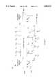
- FIG. 1is a block diagram of an adder according to the present invention.
- FIG. 2is a block diagram of a portion of an adder according to the present invention which only performs additions.
- FIGS. 3is a block diagram of a portion of an adder according to the present invention.
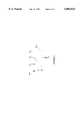
- FIG. 4is a block diagram of a multiplexer arrangement that may be utilized in constructing embodiments of the present invention.
- the present inventionis an improved adder that can be configured to perform a plurality of partial word adds or averaging operations in parallel.
- an adder 10accepts two N-bit operands 12 and 14.
- the operandsare typically stored in two of the registers in the processor of the computer.
- the present inventioncould be implemented in forms of circuitry that are not included in computers.
- adder 10When operated as a conventional adder, adder 10 generates an N bit output word 16 having the two's complement sum of X and Y and a 1-bit carry-out.
- the bits of output 16 of adder 10will be denoted by Z i in the following discussion.
- the result of the additionis typically stored back into one of the CPU registers.
- bits in the various wordswill be numbered from least significant to most significant. That is, X 0 is the least significant bit of operand X, and X N-1 is the most significant bit of the X operand. The same convention will be used for the Y and Z words.
- the present inventionallows each of the operands to be divided into a plurality of sub-words.
- the present inventionwill be explained first in terms of a single division of each of the operands into partial operands.
- the first k bits of the X operand, X 0 through X k-1are the bits of the first partial operand 18 of the X word
- the remaining bits, X k through X N-1are the bits of the second partial operand 17 of the X word.
- the Y operandis similarly divided into partial words 19 and 20.
- bits Z 0 through Z k-1are the bits of the sum of partial operands 18 and 20, and bits Z k through Z N-1 are the bits of the sum of partial operands 17 and 19, respectively.
- bits Z 0 through Z k-1are the bits of the average of partial operands 18 and 20, and bits Z k through Z N-1 are the bits of the average of partial operands 17 and 19, respectively.
- FIG. 2is a block diagram of a portion of an adder 30 according to the present invention which only performs additions. That is, adder 30 does not perform averaging calculations.
- Adder 30is constructed from an array of one bit adder stages.
- the present inventiondiffers from a conventional adder in that the stages may be decoupled to allow the adder to perform parallel additions on the partial words.
- Each single bit adderadds two bits, one from the X operand and one from the Y operand, and a carry bit from the previous stage in the adder, denoted by C i for the i th stage, to generate a sum bit and a new carry bit.
- the two stages shown in FIG. 2are the single bit adders used to add the most significant bits of partial operands 18 and 20 and the least significant bits of partial operands 17 and 19.
- Single bit adder 31for example, adds bits C k-2 , X k-1 and Y k-1 to generate sum bit S k-1 and carry bit C k-1 .
- the stage of the adder that adds bits X p and Y p to generate a sum bit S pwill be referred to as the p th stage of the adder.
- the carry bit from each stageis propagated to the next stage by connecting the carry bit input of each stage to the carry bit output of the stage before it in the array of one bit adders.
- the carry bit from the stage just before the boundary separating the two partial operandsis connected to a blocking circuit 33.
- blocking circuit 33connects the carry output of single bit adder 31 to the carry input of single bit adder 32.
- adder 30is being used to perform two adds in parallel with partial word boundary between bits k-1 and k in each register, then blocking circuit 33 merely prevents the carry bit from single bit adder 31 from propagating to the carry input of single bit adder 32. This is accomplished in response to a 1-bit signal M k . The manner in which the bits M k are specified will be discussed in more detail below.
- the carry bit from the single bit adder operating on the most significant bit of the operandsis used to detect overflows. If this feature is to be implemented for each of the partial operands, the carry bit from the most significant bit additions of each of the partial operands is connected to an appropriate overflow circuit.
- the carry bitsare ORed together and the resultant bit used to detect an overflow. This bit can be used to trigger a trap on overflow or it may be ORed with the contents of a single bit register. In the later case, the program can check the contents of the register to determine if any operation since the last time the register was checked has resulted in an overflow.
- the present inventioncan be constructed from a conventional adder merely by including a blocking circuit such as blocking circuit 33 between each pair of stages that could span the boundary between two partial operands. If the X and Y inputs are to be divisible into an arbitrary number of partial operands of arbitrary size, then a blocking section is included between each pair of single bit adders.
- the blocking sectionsare configured by a mask having bits M k that specify the location of the most significant bit of each partial operand. This mask will be referred to as the boundary mask in the following discussion.
- the bits of the maskmay be stored in a register in the adder or may be generated directly from the instruction being executed by the instruction decoding circuitry of the processor in which the adder is located.
- Blocking circuit 33replaces the carry bit by 0 during an addition in which the adder is divided into sub-adders with a boundary at the blocking circuit. If the adder is to be also used for 2's complement subtractions in which the adder is likewise divided, the carry bit must be forced to be a 1 instead of a 0.
- Blocking circuit 33 shown in FIG. 2implements both additions and subtractions by providing an input F having a value of either "0" or "1". When a boundary is active at blocking circuit 33, the value of F is the value presented to the next stage. If the boundary is inactive, then blocking circuit 33 merely transmits the carry bit, C k-1 , to the next stage.
- the above-described embodiments of the present inventiondo not perform averaging computations. While these embodiments provide significant advantages over the prior art, the preferred embodiment of the present invention provides additional hardware that provides the capability of computing averages.
- the additional hardware required to perform averaging computationswill now be discussed.
- the average of two operandsis the sum of the two operands divided by two. A division by two is equivalent to shifting the sum of the two operands to the right by one bit. The least significant bit of the sum is lost.
- the most significant bit of the averageis the carry output of the single bit adder operating on the most significant bit of the partial operands.
- stage adding the least significant bits of the partial operandsdiscards its sum bit when performing an average computation.
- This type of stagewill be referred to as a least significant bit stage in the following discussion.
- the stage adding the most significant bits of a partial operandmust route the carry bit generated thereby to the most significant bit of the result, and its sum bit to the next most significant bit of the result in addition to breaking the carry propagation chain.
- This type of stagewill be referred to as a most significant bit stage in the following discussion.
- Stages that add bits between the least and most significant bitsmust route their sum bits to a location one position to the right of the position used when the stages performed addition. That is, the i th stage routes its sum bit to Z i-1 .
- This type of stagewill be referred to as an interior bit stage in the following discussion.
- each adder stagemust be capable of functioning in at most two of the three roles described above.
- Stage (N-1)needs only perform as a most significant bit stage.
- stage 0needs only to perform as a least significant bit stage. All other stages must be capable of operating as interior bit stages when the adder is used for full word additions.
- those stages that can become the most or least significant bit stages of a parallel sub-word add or averagemust be capable of switching to those configurations.
- FIG. 3is a block diagram of a portion of an adder 100 according to the present invention.
- Adder 100is constructed from a plurality of 4-bit adding sections of which adding section 102 is exemplary. Adding section 102 operates on bits q through q+3 of the X and Y registers to generate sum bits S q through S q+3 .
- Each adding sectionis functionally equivalent to 4 of the single bit adders described above in that each adding section receives 4 bits from the X register, 4 bits from the Y register and generates the corresponding four sum bits.
- adding section 102generates a carry bit C q+3 and receives carry bit C q-1 .
- Blocking circuits 110 and 112are shown on each side of adding section 102.
- the i th sum bit, S iis routed to the i th output bit, Z i , of the adder.
- Each output line Z iis connected to a multiplexer.
- Multiplexers 122 and 123are examples of such multiplexers.
- the second type of multiplexersare those that are connected to output lines that can either be an internal bit or a most significant bit of a result. Such a multiplexer is shown at 121. These multiplexers will be referred to as most significant bit multiplexers.
- a most significant bit multiplexeris a 3-to-1 multiplexer which operates in response to A and the mask bit that determines if the multiplexer is connected to a most significant bit of a result. If A is false, then a most significant bit multiplexer connects Z i to S i . If A is true and the mask bit is also true, then a most significant bit multiplexer connects Z i to C i , where C i is the carry bit generated by the stage that generated S i .
- the most significant bit multiplexerconnects Z i to S i+1 . It should be noted that the multiplexer connected to Z N-1 is a most significant bit multiplexer in which a 2-to-1 multiplexer is sufficient, since this multiplexer can never be an interior multiplexer.
- the third type of multiplexersare those that are connected to output lines that can either be an internal bit or a least significant bit of a result. Such a multiplexer is shown at 124. These will be referred to as least significant bit multiplexers. If the result of the average operation is to be truncated, i.e., the bit shifted out is to be ignored in determining the result, a least significant bit multiplexer is the same as an internal bit multiplexer.
- While truncationmay be used as a method of rounding the result of an integer divide by shifting right, it can cause undesirable problems that can be prevented by other forms of rounding.
- an imageis to be reduced in size by averaging adjacent pixels in the image. That is, each group of 4 pixels is to be replaced by one pixel having a value equal to the average of the 4 pixels replaced.
- the imageis represented by an I ⁇ I pixel array.
- the pixel reductioncan be accomplished by averaging the odd and even rows in the array to generate an I ⁇ I/2 pixel array.
- the odd and even columns of this intermediate arrayare then averaged to generate the final (I/2) ⁇ (I/2) array.
- the final imagewill have different statistical properties than the original image. For example, the reduced image will have a lower average light intensity then the original array. It is often important that this type of artifact be avoided.
- the present inventionprovides a means for avoiding this type of biased rounding.
- the multiplexerselects the signal (S i+ 1 OR S i ) for connection to Z i when A is true and the mask bit indicates that the multiplexer in question is the least significant bit of a result.
- S iis connected to Z i .
- the multiplexerconnects Z i to S i+1 .
- Multiplexer arrangement 200is constructed from a 4-to-1 multiplexer 201. It is assumed that the multiplexer is connected to output line Z q in the following discussion. Multiplexer 201 either couples S q+1 , S q , C q or (S q+1 OR S q ) to Z q depending on the state of the average signal and mask bits. Since multiplexer 201 must function properly both as a least significant bit multiplexer or a most significant bit multiplexer, it must be able to determine the state of both M q and M q+1 .
- the present inventionalso improves the overall computational efficiency of many types of computation in which the data is packed into words at the beginning of the computation.
- the image size reduction problem discussed aboveas it would be carried out on a computer having a 32-bit word size. If each pixel is represented by a one byte integer, the image data will typically be packed into words to save storage space. Hence, each horizontal line in the image will be represented by I/4 32-bit words.
- a word containing 4 pixels of the odd numbered linecan be input to the X register and the corresponding word from the even numbered line input to the Y register.
- the contents of the Z registercan then be stored directly to memory as one packed word of the resultant image line. This operation can be carried out without having to unpack the individual bytes and repack the result.
- the present inventionallows 4 pixels to be processed with a single add instruction and avoids the packing and unpacking instructions needed with conventional adders.
- the present inventionautomatically generates the average of the two pixels, thereby eliminating one shift operation after each add.
- the parallel sub-word add instructionis no more complex than a conventional full word add instruction.
- a conventional full word addthe programmer specifies two registers having the operands and a third register to hold the result.
- the present inventionlikewise, requires only the specification of three registers. If only a few possible configurations of the adder in partial operand fields are possible, these configurations can be included in the add instruction and the instruction decode circuitry can then generate the corresponding mask bits. Hence, no additional instructions are needed to setup the adder.
- the add instructioncould specify a plurality of registers to receive the sums, each sum being loaded in the least significant bits of the register.
- the resultcould be sent directly to locations other than register, e.g. memory or other functional units.
- the operandscould originate from other functional units or memory.
- carry-look ahead architectureis used because it has smaller delays.
- carry look-ahead addersthe carry generation circuitry produces a propagate and a generate signal corresponding to each bit of the adder. These signals may be used in a manner analogous to the carry bits described above to allow the adder to be broken into parallel sub-word adders.
- a blocking circuitsuch as blocking circuit 33 shown in FIG.
- the blocking circuitdoes not alter the values of the propagate and generate bits corresponding to stage k.
Landscapes
- Engineering & Computer Science (AREA)
- Physics & Mathematics (AREA)
- General Physics & Mathematics (AREA)
- Theoretical Computer Science (AREA)
- Computational Mathematics (AREA)
- Mathematical Analysis (AREA)
- Pure & Applied Mathematics (AREA)
- Mathematical Optimization (AREA)
- Computing Systems (AREA)
- General Engineering & Computer Science (AREA)
- Complex Calculations (AREA)
- Advance Control (AREA)
Abstract
Description
Claims (18)
Priority Applications (4)
| Application Number | Priority Date | Filing Date | Title |
|---|---|---|---|
| US08/158,649US5883824A (en) | 1993-11-29 | 1993-11-29 | Parallel adding and averaging circuit and method |
| DE69435047TDE69435047T2 (en) | 1993-11-29 | 1994-08-02 | Circuit and method for parallel addition and averaging |
| EP94112045AEP0656582B1 (en) | 1993-11-29 | 1994-08-02 | Parallel adding and averaging circuit and method |
| JP29423194AJP3729881B2 (en) | 1993-11-29 | 1994-11-29 | Circuit and method for performing parallel addition and averaging |
Applications Claiming Priority (1)
| Application Number | Priority Date | Filing Date | Title |
|---|---|---|---|
| US08/158,649US5883824A (en) | 1993-11-29 | 1993-11-29 | Parallel adding and averaging circuit and method |
Publications (1)
| Publication Number | Publication Date |
|---|---|
| US5883824Atrue US5883824A (en) | 1999-03-16 |
Family
ID=22569081
Family Applications (1)
| Application Number | Title | Priority Date | Filing Date |
|---|---|---|---|
| US08/158,649Expired - LifetimeUS5883824A (en) | 1993-11-29 | 1993-11-29 | Parallel adding and averaging circuit and method |
Country Status (4)
| Country | Link |
|---|---|
| US (1) | US5883824A (en) |
| EP (1) | EP0656582B1 (en) |
| JP (1) | JP3729881B2 (en) |
| DE (1) | DE69435047T2 (en) |
Cited By (31)
| Publication number | Priority date | Publication date | Assignee | Title |
|---|---|---|---|---|
| US6003125A (en)* | 1997-01-24 | 1999-12-14 | Texas Instruments Incorporated | High performance adder for multiple parallel add operations |
| US6141675A (en)* | 1995-09-01 | 2000-10-31 | Philips Electronics North America Corporation | Method and apparatus for custom operations |
| US6211892B1 (en)* | 1998-03-31 | 2001-04-03 | Intel Corporation | System and method for performing an intra-add operation |
| US20020010847A1 (en)* | 1998-03-31 | 2002-01-24 | Mohammad Abdallah | Executing partial-width packed data instructions |
| US20020059355A1 (en)* | 1995-08-31 | 2002-05-16 | Intel Corporation | Method and apparatus for performing multiply-add operations on packed data |
| US6408320B1 (en)* | 1998-01-27 | 2002-06-18 | Texas Instruments Incorporated | Instruction set architecture with versatile adder carry control |
| US6418529B1 (en) | 1998-03-31 | 2002-07-09 | Intel Corporation | Apparatus and method for performing intra-add operation |
| US6449629B1 (en)* | 1999-05-12 | 2002-09-10 | Agere Systems Guardian Corp. | Three input split-adder |
| US6512523B1 (en)* | 2000-03-27 | 2003-01-28 | Intel Corporation | Accurate averaging of elements using integer averaging |
| US20030088603A1 (en)* | 2001-11-06 | 2003-05-08 | Broadcom Corporation | SIMD addition circuit |
| US20030097389A1 (en)* | 2001-11-21 | 2003-05-22 | Ashley Saulsbury | Methods and apparatus for performing pixel average operations |
| US20030225804A1 (en)* | 2002-05-30 | 2003-12-04 | Khieu Cong Q. | Average code generation circuit |
| US20040015533A1 (en)* | 1995-08-16 | 2004-01-22 | Microunity Systems Engineering, Inc. | Multiplier array processing system with enhanced utilization at lower precision |
| US20040049663A1 (en)* | 1995-08-16 | 2004-03-11 | Microunity Systems Engineering, Inc. | System with wide operand architecture and method |
| US20040059889A1 (en)* | 1998-03-31 | 2004-03-25 | Macy William W. | Method and apparatus for performing efficient transformations with horizontal addition and subtraction |
| US20040073585A1 (en)* | 2002-10-15 | 2004-04-15 | David Dahan | 3-input arithmetic logic unit |
| US20040073589A1 (en)* | 2001-10-29 | 2004-04-15 | Eric Debes | Method and apparatus for performing multiply-add operations on packed byte data |
| US20040083353A1 (en)* | 1998-03-31 | 2004-04-29 | Patrice Roussel | Staggering execution of a single packed data instruction using the same circuit |
| US6748411B1 (en)* | 2000-11-20 | 2004-06-08 | Agere Systems Inc. | Hierarchical carry-select multiple-input split adder |
| US20040117422A1 (en)* | 1995-08-31 | 2004-06-17 | Eric Debes | Method and apparatus for performing multiply-add operations on packed data |
| US6795841B2 (en)* | 2000-05-23 | 2004-09-21 | Arm Limited | Parallel processing of multiple data values within a data word |
| US20050138099A1 (en)* | 2003-12-17 | 2005-06-23 | Fujitsu Limited | Method and apparatus for averaging parity protected binary numbers |
| US7395302B2 (en) | 1998-03-31 | 2008-07-01 | Intel Corporation | Method and apparatus for performing horizontal addition and subtraction |
| US20080222398A1 (en)* | 1995-08-16 | 2008-09-11 | Micro Unity Systems Engineering, Inc. | Programmable processor with group floating-point operations |
| US20090083498A1 (en)* | 1995-08-16 | 2009-03-26 | Craig Hansen | Programmable processor and method with wide operations |
| US20090097771A1 (en)* | 2007-10-16 | 2009-04-16 | Broadcom Corporation | In-place averaging of packed pixel data |
| WO2009035561A3 (en)* | 2007-09-12 | 2009-06-11 | Vns Portfolio Llc | Carry-select adder |
| US20090158012A1 (en)* | 1995-08-16 | 2009-06-18 | Microunity Systems Engineering, Inc. | Method and Apparatus for Performing Improved Group Instructions |
| US20100042903A1 (en)* | 2008-08-15 | 2010-02-18 | Lsi Corporation | Reconfigurable adder |
| US20120127182A1 (en)* | 2010-11-23 | 2012-05-24 | Microsoft Corporation | Parallel processing of pixel data |
| US20140214913A1 (en)* | 2013-01-28 | 2014-07-31 | Samsung Electronics Co., Ltd. | Adder capable of supporting addition and subtraction of up to n-bit data and method of supporting addition and subtraction of a plurality of data type using the adder |
Citations (8)
| Publication number | Priority date | Publication date | Assignee | Title |
|---|---|---|---|---|
| US3987291A (en)* | 1975-05-01 | 1976-10-19 | International Business Machines Corporation | Parallel digital arithmetic device having a variable number of independent arithmetic zones of variable width and location |
| US4137568A (en)* | 1977-04-11 | 1979-01-30 | Pitney-Bowes, Inc. | Circuit for establishing the average value of a number of input values |
| US4707800A (en)* | 1985-03-04 | 1987-11-17 | Raytheon Company | Adder/substractor for variable length numbers |
| US4768160A (en)* | 1985-04-16 | 1988-08-30 | Nec Corporation | Arithmetic unit with simple overflow detection system |
| US4789953A (en)* | 1985-03-19 | 1988-12-06 | Battelle-Institut E.V. | Circuit arrangement for averaging |
| US4914617A (en)* | 1987-06-26 | 1990-04-03 | International Business Machines Corporation | High performance parallel binary byte adder |
| US5047975A (en)* | 1987-11-16 | 1991-09-10 | Intel Corporation | Dual mode adder circuitry with overflow detection and substitution enabled for a particular mode |
| US5189636A (en)* | 1987-11-16 | 1993-02-23 | Intel Corporation | Dual mode combining circuitry |
Family Cites Families (2)
| Publication number | Priority date | Publication date | Assignee | Title |
|---|---|---|---|---|
| JPS59161731A (en)* | 1983-03-07 | 1984-09-12 | Hitachi Ltd | Barrel shifter |
| JPS6124331A (en)* | 1984-07-12 | 1986-02-03 | Nec Corp | Analog-digital converter |
- 1993
- 1993-11-29USUS08/158,649patent/US5883824A/ennot_activeExpired - Lifetime
- 1994
- 1994-08-02EPEP94112045Apatent/EP0656582B1/ennot_activeExpired - Lifetime
- 1994-08-02DEDE69435047Tpatent/DE69435047T2/ennot_activeExpired - Fee Related
- 1994-11-29JPJP29423194Apatent/JP3729881B2/ennot_activeExpired - Fee Related
Patent Citations (8)
| Publication number | Priority date | Publication date | Assignee | Title |
|---|---|---|---|---|
| US3987291A (en)* | 1975-05-01 | 1976-10-19 | International Business Machines Corporation | Parallel digital arithmetic device having a variable number of independent arithmetic zones of variable width and location |
| US4137568A (en)* | 1977-04-11 | 1979-01-30 | Pitney-Bowes, Inc. | Circuit for establishing the average value of a number of input values |
| US4707800A (en)* | 1985-03-04 | 1987-11-17 | Raytheon Company | Adder/substractor for variable length numbers |
| US4789953A (en)* | 1985-03-19 | 1988-12-06 | Battelle-Institut E.V. | Circuit arrangement for averaging |
| US4768160A (en)* | 1985-04-16 | 1988-08-30 | Nec Corporation | Arithmetic unit with simple overflow detection system |
| US4914617A (en)* | 1987-06-26 | 1990-04-03 | International Business Machines Corporation | High performance parallel binary byte adder |
| US5047975A (en)* | 1987-11-16 | 1991-09-10 | Intel Corporation | Dual mode adder circuitry with overflow detection and substitution enabled for a particular mode |
| US5189636A (en)* | 1987-11-16 | 1993-02-23 | Intel Corporation | Dual mode combining circuitry |
Non-Patent Citations (8)
| Title |
|---|
| Information Processing Letter, Amsterdam, Jul. 1977, vol. 3, No. 6, "Should The Stable Rounding Rule Be Radix-Dependent?", Keir, pp. 188-189. |
| Information Processing Letter, Amsterdam, Jul. 1977, vol. 3, No. 6, Should The Stable Rounding Rule Be Radix Dependent , Keir, pp. 188 189.* |
| Ire Wescon Convention Record, Paper 16/4, Sep. 1977, North Hollywood, CA USA "The Next Generation Four-Bit Bipolar Microprocessor Slice", Coleman et. al., pp. 1-19. |
| Ire Wescon Convention Record, Paper 16/4, Sep. 1977, North Hollywood, CA USA The Next Generation Four Bit Bipolar Microprocessor Slice , Coleman et. al., pp. 1 19.* |
| Patent Abstracts of Japan, vol. 10, No. 175, (E 413) Jun. 20, 1986, Pat. No. P61024331, (Nippon Denki) * Abstract*.* |
| Patent Abstracts of Japan, vol. 10, No. 175, (E-413) Jun. 20, 1986, Pat. No. P61024331, (Nippon Denki) * Abstract*. |
| Patent Abstracts of Japan, vol. 9, No. 13, (P 328) Jan. 19, 1985, Pat. No. P59161731, (Hitachi Seisakusho) * Abstract*.* |
| Patent Abstracts of Japan, vol. 9, No. 13, (P-328) Jan. 19, 1985, Pat. No. P59161731, (Hitachi Seisakusho) * Abstract*. |
Cited By (88)
| Publication number | Priority date | Publication date | Assignee | Title |
|---|---|---|---|---|
| US20080177986A1 (en)* | 1995-08-16 | 2008-07-24 | Microunity Systems | Method and software for group data operations |
| US7660972B2 (en) | 1995-08-16 | 2010-02-09 | Microunity Systems Engineering, Inc | Method and software for partitioned floating-point multiply-add operation |
| US20080162882A1 (en)* | 1995-08-16 | 2008-07-03 | Microunity Systems | System and apparatus for group data operations |
| US8289335B2 (en) | 1995-08-16 | 2012-10-16 | Microunity Systems Engineering, Inc. | Method for performing computations using wide operands |
| US8117426B2 (en) | 1995-08-16 | 2012-02-14 | Microunity Systems Engineering, Inc | System and apparatus for group floating-point arithmetic operations |
| US8001360B2 (en) | 1995-08-16 | 2011-08-16 | Microunity Systems Engineering, Inc. | Method and software for partitioned group element selection operation |
| US7987344B2 (en) | 1995-08-16 | 2011-07-26 | Microunity Systems Engineering, Inc. | Multithreaded programmable processor and system with partitioned operations |
| US7849291B2 (en) | 1995-08-16 | 2010-12-07 | Microunity Systems Engineering, Inc. | Method and apparatus for performing improved group instructions |
| US7818548B2 (en) | 1995-08-16 | 2010-10-19 | Microunity Systems Engineering, Inc. | Method and software for group data operations |
| US7730287B2 (en) | 1995-08-16 | 2010-06-01 | Microunity Systems Engineering, Inc. | Method and software for group floating-point arithmetic operations |
| US7660973B2 (en) | 1995-08-16 | 2010-02-09 | Microunity Systems Engineering, Inc. | System and apparatus for group data operations |
| US7653806B2 (en) | 1995-08-16 | 2010-01-26 | Microunity Systems Engineering, Inc. | Method and apparatus for performing improved group floating-point operations |
| US7565515B2 (en) | 1995-08-16 | 2009-07-21 | Microunity Systems Engineering, Inc. | Method and software for store multiplex operation |
| US20040015533A1 (en)* | 1995-08-16 | 2004-01-22 | Microunity Systems Engineering, Inc. | Multiplier array processing system with enhanced utilization at lower precision |
| US20040049663A1 (en)* | 1995-08-16 | 2004-03-11 | Microunity Systems Engineering, Inc. | System with wide operand architecture and method |
| US20090158012A1 (en)* | 1995-08-16 | 2009-06-18 | Microunity Systems Engineering, Inc. | Method and Apparatus for Performing Improved Group Instructions |
| US7526635B2 (en) | 1995-08-16 | 2009-04-28 | Micounity Systems Engineering, Inc. | Programmable processor and system for store multiplex operation |
| US7516308B2 (en) | 1995-08-16 | 2009-04-07 | Microunity Systems Engineering, Inc. | Processor for performing group floating-point operations |
| US20090083498A1 (en)* | 1995-08-16 | 2009-03-26 | Craig Hansen | Programmable processor and method with wide operations |
| US7509366B2 (en) | 1995-08-16 | 2009-03-24 | Microunity Systems Engineering, Inc. | Multiplier array processing system with enhanced utilization at lower precision |
| US7464252B2 (en) | 1995-08-16 | 2008-12-09 | Microunity Systems Engineering, Inc. | Programmable processor and system for partitioned floating-point multiply-add operation |
| US20040153632A1 (en)* | 1995-08-16 | 2004-08-05 | Microunity Systems Engineering, Inc. | Method and software for partitioned group element selection operation |
| US7430655B2 (en) | 1995-08-16 | 2008-09-30 | Microunity Systems Engineering, Inc. | Method and software for multithreaded processor with partitioned operations |
| US20040205324A1 (en)* | 1995-08-16 | 2004-10-14 | Microunity Systems Engineering, Inc. | Method and software for partitioned floating-point multiply-add operation |
| US20080222398A1 (en)* | 1995-08-16 | 2008-09-11 | Micro Unity Systems Engineering, Inc. | Programmable processor with group floating-point operations |
| US20040205325A1 (en)* | 1995-08-16 | 2004-10-14 | Microunity Systems Engineering, Inc. | Method and software for store multiplex operation |
| US20040210745A1 (en)* | 1995-08-16 | 2004-10-21 | Microunity Systems Engineering, Inc. | Multithreaded programmable processor and system with partitioned operations |
| US20040210746A1 (en)* | 1995-08-16 | 2004-10-21 | Microunity Systems Engineering, Inc. | Programmable processor and system for store multiplex operation |
| US20040215942A1 (en)* | 1995-08-16 | 2004-10-28 | Microunity Systems Engineering, Inc. | Method and software for multithreaded processor with partitioned operations |
| US20040205096A1 (en)* | 1995-08-16 | 2004-10-14 | Microunity Systems Engineering, Inc. | Programmable processor and system for partitioned floating-point multiply-add operation |
| US20080091925A1 (en)* | 1995-08-16 | 2008-04-17 | Microunity Systems | Method and software for group floating-point arithmetic operations |
| US20080091758A1 (en)* | 1995-08-16 | 2008-04-17 | Microunity Systems | System and apparatus for group floating-point arithmetic operations |
| US20080059767A1 (en)* | 1995-08-16 | 2008-03-06 | Microunity Systems Engineering, Inc. | Method and Apparatus for Performing Improved Group Floating-Point Operations |
| US8185571B2 (en) | 1995-08-31 | 2012-05-22 | Intel Corporation | Processor for performing multiply-add operations on packed data |
| US20040117422A1 (en)* | 1995-08-31 | 2004-06-17 | Eric Debes | Method and apparatus for performing multiply-add operations on packed data |
| US8745119B2 (en) | 1995-08-31 | 2014-06-03 | Intel Corporation | Processor for performing multiply-add operations on packed data |
| US8725787B2 (en) | 1995-08-31 | 2014-05-13 | Intel Corporation | Processor for performing multiply-add operations on packed data |
| US8626814B2 (en) | 1995-08-31 | 2014-01-07 | Intel Corporation | Method and apparatus for performing multiply-add operations on packed data |
| US8396915B2 (en) | 1995-08-31 | 2013-03-12 | Intel Corporation | Processor for performing multiply-add operations on packed data |
| US7509367B2 (en) | 1995-08-31 | 2009-03-24 | Intel Corporation | Method and apparatus for performing multiply-add operations on packed data |
| US7395298B2 (en) | 1995-08-31 | 2008-07-01 | Intel Corporation | Method and apparatus for performing multiply-add operations on packed data |
| US8793299B2 (en) | 1995-08-31 | 2014-07-29 | Intel Corporation | Processor for performing multiply-add operations on packed data |
| US7424505B2 (en) | 1995-08-31 | 2008-09-09 | Intel Corporation | Method and apparatus for performing multiply-add operations on packed data |
| US20090265409A1 (en)* | 1995-08-31 | 2009-10-22 | Peleg Alexander D | Processor for performing multiply-add operations on packed data |
| US8495123B2 (en) | 1995-08-31 | 2013-07-23 | Intel Corporation | Processor for performing multiply-add operations on packed data |
| US20020059355A1 (en)* | 1995-08-31 | 2002-05-16 | Intel Corporation | Method and apparatus for performing multiply-add operations on packed data |
| US6141675A (en)* | 1995-09-01 | 2000-10-31 | Philips Electronics North America Corporation | Method and apparatus for custom operations |
| US6003125A (en)* | 1997-01-24 | 1999-12-14 | Texas Instruments Incorporated | High performance adder for multiple parallel add operations |
| US6408320B1 (en)* | 1998-01-27 | 2002-06-18 | Texas Instruments Incorporated | Instruction set architecture with versatile adder carry control |
| US20020010847A1 (en)* | 1998-03-31 | 2002-01-24 | Mohammad Abdallah | Executing partial-width packed data instructions |
| US6970994B2 (en) | 1998-03-31 | 2005-11-29 | Intel Corporation | Executing partial-width packed data instructions |
| US20030050941A1 (en)* | 1998-03-31 | 2003-03-13 | Patrice Roussel | Apparatus and method for performing intra-add operation |
| US7467286B2 (en) | 1998-03-31 | 2008-12-16 | Intel Corporation | Executing partial-width packed data instructions |
| US6961845B2 (en) | 1998-03-31 | 2005-11-01 | Intel Corporation | System to perform horizontal additions |
| US7366881B2 (en) | 1998-03-31 | 2008-04-29 | Intel Corporation | Method and apparatus for staggering execution of an instruction |
| US20040083353A1 (en)* | 1998-03-31 | 2004-04-29 | Patrice Roussel | Staggering execution of a single packed data instruction using the same circuit |
| US6925553B2 (en) | 1998-03-31 | 2005-08-02 | Intel Corporation | Staggering execution of a single packed data instruction using the same circuit |
| US20050216706A1 (en)* | 1998-03-31 | 2005-09-29 | Mohammad Abdallah | Executing partial-width packed data instructions |
| US20040059889A1 (en)* | 1998-03-31 | 2004-03-25 | Macy William W. | Method and apparatus for performing efficient transformations with horizontal addition and subtraction |
| US7392275B2 (en) | 1998-03-31 | 2008-06-24 | Intel Corporation | Method and apparatus for performing efficient transformations with horizontal addition and subtraction |
| US6211892B1 (en)* | 1998-03-31 | 2001-04-03 | Intel Corporation | System and method for performing an intra-add operation |
| US7395302B2 (en) | 1998-03-31 | 2008-07-01 | Intel Corporation | Method and apparatus for performing horizontal addition and subtraction |
| US6418529B1 (en) | 1998-03-31 | 2002-07-09 | Intel Corporation | Apparatus and method for performing intra-add operation |
| US6449629B1 (en)* | 1999-05-12 | 2002-09-10 | Agere Systems Guardian Corp. | Three input split-adder |
| US6512523B1 (en)* | 2000-03-27 | 2003-01-28 | Intel Corporation | Accurate averaging of elements using integer averaging |
| US6795841B2 (en)* | 2000-05-23 | 2004-09-21 | Arm Limited | Parallel processing of multiple data values within a data word |
| US6748411B1 (en)* | 2000-11-20 | 2004-06-08 | Agere Systems Inc. | Hierarchical carry-select multiple-input split adder |
| US20040073589A1 (en)* | 2001-10-29 | 2004-04-15 | Eric Debes | Method and apparatus for performing multiply-add operations on packed byte data |
| US7430578B2 (en) | 2001-10-29 | 2008-09-30 | Intel Corporation | Method and apparatus for performing multiply-add operations on packed byte data |
| US20030088603A1 (en)* | 2001-11-06 | 2003-05-08 | Broadcom Corporation | SIMD addition circuit |
| US7219118B2 (en)* | 2001-11-06 | 2007-05-15 | Broadcom Corporation | SIMD addition circuit |
| US20030097389A1 (en)* | 2001-11-21 | 2003-05-22 | Ashley Saulsbury | Methods and apparatus for performing pixel average operations |
| US7558816B2 (en)* | 2001-11-21 | 2009-07-07 | Sun Microsystems, Inc. | Methods and apparatus for performing pixel average operations |
| US20030225804A1 (en)* | 2002-05-30 | 2003-12-04 | Khieu Cong Q. | Average code generation circuit |
| US7254599B2 (en)* | 2002-05-30 | 2007-08-07 | Sun Microsystems, Inc. | Average code generation circuit |
| US20040073585A1 (en)* | 2002-10-15 | 2004-04-15 | David Dahan | 3-input arithmetic logic unit |
| US7149768B2 (en)* | 2002-10-15 | 2006-12-12 | Ceva D.S.P. Ltd. | 3-input arithmetic logic unit |
| US20050138099A1 (en)* | 2003-12-17 | 2005-06-23 | Fujitsu Limited | Method and apparatus for averaging parity protected binary numbers |
| US7437399B2 (en)* | 2003-12-17 | 2008-10-14 | Fujitsu Limited | Method and apparatus for averaging parity protected binary numbers |
| WO2009035561A3 (en)* | 2007-09-12 | 2009-06-11 | Vns Portfolio Llc | Carry-select adder |
| US8036484B2 (en)* | 2007-10-16 | 2011-10-11 | Broadcom Corporation | In-place averaging of packed pixel data |
| US20090097771A1 (en)* | 2007-10-16 | 2009-04-16 | Broadcom Corporation | In-place averaging of packed pixel data |
| US8407567B2 (en)* | 2008-08-15 | 2013-03-26 | Lsi Corporation | Reconfigurable adder |
| US20100042903A1 (en)* | 2008-08-15 | 2010-02-18 | Lsi Corporation | Reconfigurable adder |
| US20120127182A1 (en)* | 2010-11-23 | 2012-05-24 | Microsoft Corporation | Parallel processing of pixel data |
| US9524572B2 (en)* | 2010-11-23 | 2016-12-20 | Microsoft Technology Licensing, Llc | Parallel processing of pixel data |
| US20140214913A1 (en)* | 2013-01-28 | 2014-07-31 | Samsung Electronics Co., Ltd. | Adder capable of supporting addition and subtraction of up to n-bit data and method of supporting addition and subtraction of a plurality of data type using the adder |
| US9842085B2 (en)* | 2013-01-28 | 2017-12-12 | Samsung Electronics Co., Ltd. | Adder capable of supporting addition and subtraction of up to n-bit data and method of supporting addition and subtraction of a plurality of data type using the adder |
Also Published As
| Publication number | Publication date |
|---|---|
| JP3729881B2 (en) | 2005-12-21 |
| JPH07210369A (en) | 1995-08-11 |
| EP0656582B1 (en) | 2007-11-21 |
| DE69435047T2 (en) | 2008-10-02 |
| EP0656582A1 (en) | 1995-06-07 |
| DE69435047D1 (en) | 2008-01-03 |
Similar Documents
| Publication | Publication Date | Title |
|---|---|---|
| US5883824A (en) | Parallel adding and averaging circuit and method | |
| US5390135A (en) | Parallel shift and add circuit and method | |
| US6009451A (en) | Method for generating barrel shifter result flags directly from input data | |
| USRE44190E1 (en) | Long instruction word controlling plural independent processor operations | |
| US5448509A (en) | Efficient hardware handling of positive and negative overflow resulting from arithmetic operations | |
| US6173394B1 (en) | Instruction having bit field designating status bits protected from modification corresponding to arithmetic logic unit result | |
| US5644522A (en) | Method, apparatus and system for multiply rounding using redundant coded multiply result | |
| US5446651A (en) | Split multiply operation | |
| US5961635A (en) | Three input arithmetic logic unit with barrel rotator and mask generator | |
| US5640578A (en) | Arithmetic logic unit having plural independent sections and register storing resultant indicator bit from every section | |
| US6098163A (en) | Three input arithmetic logic unit with shifter | |
| US5734880A (en) | Hardware branching employing loop control registers loaded according to status of sections of an arithmetic logic unit divided into a plurality of sections | |
| US5606677A (en) | Packed word pair multiply operation forming output including most significant bits of product and other bits of one input | |
| US5596763A (en) | Three input arithmetic logic unit forming mixed arithmetic and boolean combinations | |
| US5465224A (en) | Three input arithmetic logic unit forming the sum of a first Boolean combination of first, second and third inputs plus a second Boolean combination of first, second and third inputs | |
| US5960193A (en) | Apparatus and system for sum of plural absolute differences | |
| US5600847A (en) | Three input arithmetic logic unit with mask generator | |
| US6016538A (en) | Method, apparatus and system forming the sum of data in plural equal sections of a single data word | |
| EP0657802B1 (en) | Rotation register for orthogonal data transformation | |
| US5479166A (en) | Huffman decoding method, circuit and system employing conditional subtraction for conversion of negative numbers | |
| US5712999A (en) | Address generator employing selective merge of two independent addresses | |
| US5442581A (en) | Iterative division apparatus, system and method forming plural quotient bits per iteration | |
| US5512896A (en) | Huffman encoding method, circuit and system employing most significant bit change for size detection | |
| US5867413A (en) | Fast method of floating-point multiplication and accumulation | |
| US5689695A (en) | Conditional processor operation based upon result of two consecutive prior processor operations |
Legal Events
| Date | Code | Title | Description |
|---|---|---|---|
| AS | Assignment | Owner name:HEWLETT-PACKARD COMPANY, CALIFORNIA Free format text:ASSIGNMENT OF ASSIGNORS INTEREST;ASSIGNORS:LEE, RUBY BEI-LOH;BECK, JOHN PAUL;REEL/FRAME:006854/0097;SIGNING DATES FROM 19931119 TO 19931123 | |
| STCF | Information on status: patent grant | Free format text:PATENTED CASE | |
| AS | Assignment | Owner name:HEWLETT-PACKARD COMPANY, COLORADO Free format text:MERGER;ASSIGNOR:HEWLETT-PACKARD COMPANY;REEL/FRAME:011523/0469 Effective date:19980520 | |
| FEPP | Fee payment procedure | Free format text:PAYOR NUMBER ASSIGNED (ORIGINAL EVENT CODE: ASPN); ENTITY STATUS OF PATENT OWNER: LARGE ENTITY | |
| REMI | Maintenance fee reminder mailed | ||
| FPAY | Fee payment | Year of fee payment:4 | |
| SULP | Surcharge for late payment | ||
| FPAY | Fee payment | Year of fee payment:8 | |
| FPAY | Fee payment | Year of fee payment:12 | |
| AS | Assignment | Owner name:HEWLETT-PACKARD DEVELOPMENT COMPANY, L.P., TEXAS Free format text:ASSIGNMENT OF ASSIGNORS INTEREST;ASSIGNOR:HEWLETT-PACKARD COMPANY;REEL/FRAME:026945/0699 Effective date:20030131 | |
| AS | Assignment | Owner name:HEWLETT PACKARD ENTERPRISE DEVELOPMENT LP, TEXAS Free format text:ASSIGNMENT OF ASSIGNORS INTEREST;ASSIGNOR:HEWLETT-PACKARD DEVELOPMENT COMPANY, L.P.;REEL/FRAME:037079/0001 Effective date:20151027 |