US5883582A - Anticollision protocol for reading multiple RFID tags - Google Patents
Anticollision protocol for reading multiple RFID tagsDownload PDFInfo
- Publication number
- US5883582A US5883582AUS08/796,645US79664597AUS5883582AUS 5883582 AUS5883582 AUS 5883582AUS 79664597 AUS79664597 AUS 79664597AUS 5883582 AUS5883582 AUS 5883582A
- Authority
- US
- United States
- Prior art keywords
- devices
- radio frequency
- transmission period
- length
- integrated circuit
- Prior art date
- Legal status (The legal status is an assumption and is not a legal conclusion. Google has not performed a legal analysis and makes no representation as to the accuracy of the status listed.)
- Expired - Fee Related
Links
Images


Classifications
- G—PHYSICS
- G08—SIGNALLING
- G08B—SIGNALLING OR CALLING SYSTEMS; ORDER TELEGRAPHS; ALARM SYSTEMS
- G08B13/00—Burglar, theft or intruder alarms
- G08B13/22—Electrical actuation
- G08B13/24—Electrical actuation by interference with electromagnetic field distribution
- G08B13/2402—Electronic Article Surveillance [EAS], i.e. systems using tags for detecting removal of a tagged item from a secure area, e.g. tags for detecting shoplifting
- G08B13/2465—Aspects related to the EAS system, e.g. system components other than tags
- G08B13/2485—Simultaneous detection of multiple EAS tags
- G—PHYSICS
- G08—SIGNALLING
- G08B—SIGNALLING OR CALLING SYSTEMS; ORDER TELEGRAPHS; ALARM SYSTEMS
- G08B13/00—Burglar, theft or intruder alarms
- G08B13/02—Mechanical actuation
- G08B13/14—Mechanical actuation by lifting or attempted removal of hand-portable articles
- G—PHYSICS
- G06—COMPUTING OR CALCULATING; COUNTING
- G06K—GRAPHICAL DATA READING; PRESENTATION OF DATA; RECORD CARRIERS; HANDLING RECORD CARRIERS
- G06K7/00—Methods or arrangements for sensing record carriers, e.g. for reading patterns
- G06K7/0008—General problems related to the reading of electronic memory record carriers, independent of its reading method, e.g. power transfer
- G—PHYSICS
- G06—COMPUTING OR CALCULATING; COUNTING
- G06K—GRAPHICAL DATA READING; PRESENTATION OF DATA; RECORD CARRIERS; HANDLING RECORD CARRIERS
- G06K7/00—Methods or arrangements for sensing record carriers, e.g. for reading patterns
- G06K7/10—Methods or arrangements for sensing record carriers, e.g. for reading patterns by electromagnetic radiation, e.g. optical sensing; by corpuscular radiation
- G06K7/10009—Methods or arrangements for sensing record carriers, e.g. for reading patterns by electromagnetic radiation, e.g. optical sensing; by corpuscular radiation sensing by radiation using wavelengths larger than 0.1 mm, e.g. radio-waves or microwaves
- G06K7/10019—Methods or arrangements for sensing record carriers, e.g. for reading patterns by electromagnetic radiation, e.g. optical sensing; by corpuscular radiation sensing by radiation using wavelengths larger than 0.1 mm, e.g. radio-waves or microwaves resolving collision on the communication channels between simultaneously or concurrently interrogated record carriers.
- G06K7/10029—Methods or arrangements for sensing record carriers, e.g. for reading patterns by electromagnetic radiation, e.g. optical sensing; by corpuscular radiation sensing by radiation using wavelengths larger than 0.1 mm, e.g. radio-waves or microwaves resolving collision on the communication channels between simultaneously or concurrently interrogated record carriers. the collision being resolved in the time domain, e.g. using binary tree search or RFID responses allocated to a random time slot
- G06K7/10059—Methods or arrangements for sensing record carriers, e.g. for reading patterns by electromagnetic radiation, e.g. optical sensing; by corpuscular radiation sensing by radiation using wavelengths larger than 0.1 mm, e.g. radio-waves or microwaves resolving collision on the communication channels between simultaneously or concurrently interrogated record carriers. the collision being resolved in the time domain, e.g. using binary tree search or RFID responses allocated to a random time slot transponder driven
- G—PHYSICS
- G08—SIGNALLING
- G08B—SIGNALLING OR CALLING SYSTEMS; ORDER TELEGRAPHS; ALARM SYSTEMS
- G08B13/00—Burglar, theft or intruder alarms
- G08B13/22—Electrical actuation
- G08B13/24—Electrical actuation by interference with electromagnetic field distribution
- G08B13/2402—Electronic Article Surveillance [EAS], i.e. systems using tags for detecting removal of a tagged item from a secure area, e.g. tags for detecting shoplifting
- G08B13/2405—Electronic Article Surveillance [EAS], i.e. systems using tags for detecting removal of a tagged item from a secure area, e.g. tags for detecting shoplifting characterised by the tag technology used
- G08B13/2414—Electronic Article Surveillance [EAS], i.e. systems using tags for detecting removal of a tagged item from a secure area, e.g. tags for detecting shoplifting characterised by the tag technology used using inductive tags
- G08B13/2417—Electronic Article Surveillance [EAS], i.e. systems using tags for detecting removal of a tagged item from a secure area, e.g. tags for detecting shoplifting characterised by the tag technology used using inductive tags having a radio frequency identification chip
- G—PHYSICS
- G08—SIGNALLING
- G08B—SIGNALLING OR CALLING SYSTEMS; ORDER TELEGRAPHS; ALARM SYSTEMS
- G08B13/00—Burglar, theft or intruder alarms
- G08B13/22—Electrical actuation
- G08B13/24—Electrical actuation by interference with electromagnetic field distribution
- G08B13/2402—Electronic Article Surveillance [EAS], i.e. systems using tags for detecting removal of a tagged item from a secure area, e.g. tags for detecting shoplifting
- G08B13/2428—Tag details
- G08B13/2431—Tag circuit details
Definitions
- Tagging of articles for identification and/or theft protectionis known. For instance, many articles are identified using a bar code comprising coded information which is read by passing the bar code within view of a scanner. Many articles also include a resonant tag for use in theft detection and prevention. More recently, passive resonant security tags which return unique or semi-unique identification codes have been developed. These security tags typically include an integrated circuit which stores the identification code. Such "intelligent" security tags provide information about an article to which the tag is affixed which is detected in the zone of an interrogator. The tags are desirable because they can be interrogated rapidly, and from a distance.
- Intelligent tagging of articlesprovides substantial benefits at the point of manufacture, at the point of distribution, and at the point of sale. That is, any place where articles are stored, shelved, displayed or inventoried, intelligent tags can result in substantial cost savings.
- one function of a distribution centeris to take merchandise that has been packed and shipped in bulk, and repack the merchandise into smaller "tote" boxes. Often the tote box is packed with single units of a variety of products. Mistakes in inventory during this repacking process can be very costly and there is a possibility of shipping products to the wrong retailer.
- An intelligent tagging systemcan check the contents of tote boxes with an interrogator or point reader at high speeds and confirm exactly what is being shipped to individual retailers.
- Intelligent tagsobviate the need for such hand counting and manual data checking. Rather than hand counting a plurality of items, an employee can point an intelligent tag reader at individual product clusters on shelves and scan entire product groups in minutes. Intelligent tags also allow employees to scan a product group to learn critical expiration dates to avoid spoilage, reduce stock and maintain continuous inventory counts.
- interrogatorsinclude a means for controlling the transmission of data from individual tags, for example, by shutting individual tags off for predetermined time periods after a response signal is transmitted.
- FCCFederal Communications Commission
- tagswhich include circuitry to detect the simultaneous transmission of data by multiple tags. Upon detection of such simultaneous transmissions, the tags abort their transmissions and wait for a prescribed time prior to retransmission, usually for a period of time that is set by a random number.
- this methodrequires the tags include detection circuitry and a battery, both of which excessively increase the cost of the tag. Accordingly, there is a need for a method of detecting substantially simultaneous transmission of data by multiple tags at the same frequency located within an interrogation zone and compensating for such multiple transmissions in order to accurately read the data transmitted by each tag.
- the present inventionprovides a method of simultaneously reading multiple RFID tags located in a field of an interrogating antenna based on periodic transmissions from the tags with long non-transmission intervals between transmissions.
- the non-transmission intervalsare fixed for a given tag, but are random between tags, preferably due to manufacturing tolerances, such that no co-ordination of transmissions from the interrogating antenna is required.
- the present inventioncomprises a method of reading data from a plurality of radio frequency intelligent devices located within an interrogation zone using a one sided protocol, with the devices never being turned off.
- an interrogation devicetransmits a continuous interrogation signal.
- the interrogation signalcomprises an electromagnetic field at a first predetermined radio frequency, wherein a strength of the electromagnetic field defines the interrogation zone.
- a plurality of radio frequency intelligent devices located within the interrogation zoneare acted upon by the electromagnetic field.
- the electromagnetic fieldinduces a voltage in each intelligent device which provides power to the intelligent devices.
- each of the plurality of intelligent devices within the interrogation zonereads a respective prestored data field and repeatedly transmits a message stored therein at a second predetermined radio frequency at predetermined periodic intervals with a fixed length nontransmission interval between each transmission interval.
- a length of the non-transmission intervalis much greater than a length of the message transmission interval.
- the interrogation devicereads the message transmissions of each of the plurality of intelligent devices.
- a probability of two or more of the plurality of intelligent devices transmitting their respective messages simultaneouslyis reduced due to variations among the intelligent devices in the fixed non-transmission time and by making the length of the non-transmission interval much greater than the length of the message transmission interval.
- the present inventionalso provides a radio frequency intelligent device comprising:
- an antennaconnected to the integrated circuit, wherein exposure of the antenna to an electromagnetic field at a first predetermined radio frequency induces a voltage therein which provides power to the integrated circuit such that the data stored therein is read from the integrated circuit and repeatedly transmitted at a second predetermined radio frequency;
- the present inventionis also a radio frequency identification device comprising:
- an antenna connected to the integrated circuitcomprising an inductor and a capacitor, wherein exposure of the antenna to an electromagnetic field at a first predetermined radio frequency induces a voltage in the inductor which provides power to the integrated circuit such that the data stored therein is read and provides a continuous data output signal;
- a transmitterfor repeatedly transmitting the data output signal at a second predetermined radio frequency
- a timerfor establishing a fixed non-transmission period between each data transmission period, wherein a length of the non-transmission period is much greater than a length of the transmission period.
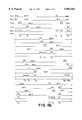
- FIG. 1is a schematic diagram of an equivalent electrical circuit of a resonant frequency identification (RFID) device in accordance with a preferred embodiment of the present invention
- FIG. 2is a schematic block diagram of an interrogator and an RFID tag in accordance with the present invention
- FIG. 3ais a timing diagram of a protocol for transmitting data from the RFID device
- FIG. 3bis a timing diagram of a preferred protocol for transmitting data from the RFID device
- FIG. 4ais a timing diagram of a plurality of tags each outputting a data signal in response to an interrogation signal according to a preferred embodiment of the present invention
- FIG. 4bis a continuation of the timing diagram of FIG. 4a;
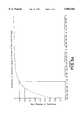
- FIG. 5ais a graph of the probability of reading a plurality of RFID devices as a function of time.
- FIG. 5bis a graph of the probability of reading a plurality of RFID devices within a predetermined time limit.
- the present inventionis directed to a method of reading multiple RFID tags or intelligent devices simultaneously.
- the methodis achieved by providing tags which continuously transmit their respective identification information for as long as the tag is within an interrogation zone.
- Each data transmissionis followed by a fixed wait period or non-transmission interval.
- the non-transmission intervalis preferably more than ten times greater than the data transmission period.
- Each tagis constructed such that electrical components within each tag include predetermined manufacturing tolerances, such that although the length of the non-transmission interval is fixed for each tag, the non-transmission interval varies between tags at least within the prescribed tolerances.
- the variation in the length of non-transmission intervals among tagscauses the transmission intervals among the tags to be skewed, or not to overlap when the tag is within the interrogation zone.
- FIG. 1a schematic diagram of an equivalent electrical circuit of a resonant frequency identification tag or device 10 in accordance with a preferred embodiment of the present invention.
- RFID tagsare generally known and applicable to a wide variety of uses.
- U.S. Pat. No. 5,430,441discloses a transponding tag which transmits a digitally encoded signal in response to an interrogation signal.
- the above disclosed tagcomprises a rigid substrate constructed from a plurality of dielectric layers and conductive layers and includes an integrated circuit embedded entirely within a hole in the substrate and tab bonded to conductive foil traces.
- the device 10comprises an antenna 12 electrically connected to an integrated circuit (IC) 14.
- the antenna 12comprises a resonant circuit which resonants at a predetermined radio frequency (RF) corresponding to a radio frequency of an associated interrogation device, as discussed in more detail hereinafter.
- RFradio frequency
- the antenna 12may comprise one or more inductive elements electrically connected to one or more capacitive elements.
- the antenna 12is formed by the combination of a single inductive element, inductor, or coil L electrically connected with a capacitive element or capacitance C ANT in a series loop.
- the operational frequency of the antenna 12depends upon the values of the inductor coil L and the capacitor C.sub. ANT.
- the size of the inductor L and the value of the capacitor C ANTare determined based upon the desired resonant frequency of the antenna 12.
- the device 10is constructed to operate at 13.56 MHZ.
- the device 10resonates at about 13.56 MHZ
- the device 10could be constructed to resonate at other frequencies and the precise resonant frequency of the device 10 is not meant to be a limitation of the present invention.
- the antenna 12may operate at radio frequencies other than 13.56 MHZ, and indeed at other frequencies, such as microwave frequencies.
- the device 10includes a single inductive element L and a single capacitor element C ANT , multiple inductor and capacitor elements could alteratively be employed.
- multiple element resonant circuitsare well known in the electronic security and surveillance art, such as described in U.S. Pat. No.
- the IC 14preferably includes a programmable memory 18, such as a 64 or 128 bit memory, for storing bits of identification data, although larger or smaller programmable memories could also be used.
- the IC 14outputs a data stream comprised of the 64 (or 128) bits of data when sufficient power is applied thereto.
- the data bits or digital value stored in the programmable memory 18can be used for a variety of purposes, such as to identify a particular object or person associated with the device 10.
- the memory 18may comprise one or more data fields for storing one or more digitally encoded messages.
- the stored digital valuemay be unique to each device 10, or in some instances, it may be desirable for two or more devices to have the same stored digital value.
- the data stored in the memory 18could be used to store product identity information, product warranty information, as well as other information, such as when and where the product was manufactured, etc.
- the IC 14when the device 10 is powered by an induced voltage, the IC 14 outputs the data stored in the programmable memory 18. The data is then transmitted at a predetermined radio frequency which is detectable by an interrogation device 20 (FIG. 2). The transmission of the data by the device 10 is termed herein a transmission period or interval.
- the IC 14also preferably includes a timer circuit 19 which establishes or defines a non-transmission period or interval, such that each data transmission interval is followed by a non-transmission interval.
- a time length of the non-transmission intervalis generally fixed. That is, the timer circuit 19 establishes a single, fixed, non-transmission interval.
- the timer circuit 19requires the device 10 to wait for a fixed length or period of time after data is transmitted therefrom until data is again transmitted therefrom. Consequently, each data transmission interval is followed by a fixed length non-transmission interval.
- the non-transmission intervalmay be established by having the timer circuit 19 generate an enable signal which enables the device 10 to transmit data.
- the timer circuit 19could interact with the memory 18 such that the memory 18 is only strobed or read at fixed intervals.
- the timer circuit 19is constructed to time or count for a predetermined, fixed length of time, after each transmission interval or memory 18 access.
- the timer circuit 19may be constructed using a variety of electrical components or devices, as is known by those of ordinary skill in the art. The specific manner in which the timer 19 is designed and the electrical components from which the timer 19 is constructed is not important. That is, the timer circuit 19 could count up, count down, or be a simple delay circuit. Although it is preferred that the timer 19 be constructed as an integral part of the IC 14 and that the timer 19 interacts with the memory 18, the timer 19 could interact with an output of the IC 14, rather than the memory 18. Also, the timer 19 could be constructed external to the IC 14. It is to be understood that the importance of the timer 19 is that it functions to assure that a data transmission interval is followed by a fixed length non-transmission interval.
- a proximity reader or interrogator device 20(FIG. 2) is used to detect and read the information transmitted by the device 10.
- the reader/interrogator 20establishes an electromagnetic field at or near the resonant frequency of the antenna 12.
- a voltageis induced on the inductive coil L, which provides power to the IC 14 at the ANT input of the IC 14.
- the IC 14internally rectifies the induced AC voltage at the ANT input to provide an internal DC voltage source.
- the internal DC voltagereaches a level that assures proper operation of the IC 14, the IC 14 functions to output the digital value stored in the programmable memory at the MOD output of the IC 14.
- the antenna 12comprises a resonant circuit.
- a modulation capacitor C MODis connected to the MOD output of the IC 14 and to the resonant circuit (antenna) 12.
- the data output pulses at the MOD outputswitch the capacitor C MOD into and out of the resonant circuit 12 by making and breaking ground connections to change the overall capacitance of the resonant circuit 12 in accordance with the stored data, which in turn changes the resonant frequency of the resonant circuit 12, detuning it from a principal operational frequency to a predetermined higher frequency.
- data pulses of the device 10are created by the tuning and detuning of the resonant circuit 12.
- the reader/interrogator 20senses the changes in the consumption of energy within its electromagnetic field to determine the digital data value output from the IC 14. Although a particular method and circuit for outputting or transmitting data to the interrogator 20 is disclosed, other means of transmitting stored data to the interrogator 20, such as other modulation techniques, are within the scope of the present invention.
- the IC 14may also include a power return or GND output and one or more additional inputs 16 which are used for programming the IC 14 (i.e. storing or altering the digital value therein) in a conventional manner.
- the IC 14comprises 128 bits of nonvolatile memory.
- the programmable memory 18could have either a greater or smaller storage capacity.
- the interrogator 20includes a transmitter 22, receiver 24, antenna assembly 26, and data processing and control circuitry 28, each having inputs and outputs.
- the transmitter 22generates an interrogation signal which is provided to the antenna assembly 26 for generating an electromagnetic field at a first predetermined radio frequency.
- the strength of the electromagnetic fielddetermines the size of the zone in which the RFID devices 10 will be powered and detected (i.e. the interrogation zone).
- the receiver 24detects changes in the electromagnetic field caused by the transmission of a data output signal by an RFID device 10.
- the output of the transmitter 22is connected to a first input of the receiver 24, and to the input of the antenna assembly 26.
- the output of the antenna assembly 26is connected to a second input of the receiver 24.
- a first and a second output of the data processing and control circuitry 28are connected to the input of the transmitter 22 and to a third input of the receiver 24, respectively Furthermore, the output of the receiver 24 is connected to the input of the data processing and control circuitry 28.
- Interrogators having this general configurationmay be built using circuitry described in U.S. Pat. Nos. 3,726,960, 3,816,708, 4,103,830 and 4,580,041, all of which are incorporated by reference in their entirety herein.
- the data processing and control circuitry of the interrogator described in these patentsare modified to append date and time data thereto (e.g. a time-stamp).
- a time clock 30is provided in the data processing and control circuitry 28 for appending the date and time data.
- the interrogator 20is preferably a hand-held device. However, other physical manifestations of the interrogator 20 are within the scope of the invention, such as a pedestal structure. Moreover, the interrogator 20 may comprise a separate structure from the transmitter 22 and an associated antenna, and from the receiver 24 and an associated antenna, as is known in the art.
- the interrogator 20can detect transmissions from a plurality of devices 10 (and thus their associated articles) located within the interrogation zone. In most instances, each of the devices 10 receive and respond to the interrogation signal at a different instant in time, even when the devices 10 are physically close together. The string of returned signals is processed to sort out the individual signals from each of the devices 10. However, if two devices 10 transmit a data signal at exactly the same time or at partially overlapping times, the interrogator 20 can detect this event and discard the data signals. Such detection circuitry is conventional and known by those of ordinary skill in the art. According to the present invention, the interrogation signal generated by the interrogator 20 is a generally continuous signal, as opposed to a periodic or pulsed signal.
- the interrogation signalis internal to the interrogator 20 and is provided to the antenna assembly 26 to generate an electromagnetic field.
- the interrogation zoneis the area within the electromagnetic field in which a voltage is induced in the intelligent device 10 sufficient to power the IC 14.
- the size of the interrogation zoneis defined by the strength of the electromagnetic field.
- the device 10As long as a device is within the interrogation zone, the device 10 continually transmits or outputs its data. In order to allow the interrogator 20 to detect and receive data from a plurality of devices 10 located within the interrogation zone, after transmission of data by a particular device 10, as previously discussed, the device 10 waits for a fixed length of time before again transmitting its data.
- the RFID device 10 output data streamcomprises memory data 32 followed by a fixed length gap or period where no data is transmitted 34.
- the memory data portion 32comprises the message being transmitted from the device 10.
- the messagemay comprise all of the bits of information stored in the programmable memory 18 or a selected number of the data bits stored in the memory 18. Note that the RFID device 10 continues to transmit its output data stream as long as the RFID device 10 is within the interrogation zone and the induced voltage from the electromagnetic field is high enough.
- the messagemay further comprise additional bits of information not stored in the data memory 18, such as for error detection and correction, or other control purposes, as will be apparent to those of skill in the art.
- FIG. 3bis a timing diagram of a preferred protocol for transmitting data stored in the RFID device 10. Similar to the protocol shown in FIG. 3a, the output data stream comprises a memory data portion 36 followed by a fixed length gap or non-transmission interval 38, and the RFID device 10 continuously outputs the data stream as long as the device 10 is within the interrogation zone and the induced voltage from the electromagnetic field is high enough.
- the difference between the protocol of FIG. 3a and the protocol of FIG. 3bis that the length of the non-transmission interval 38 is greater than the length of the memory data portion 36 in FIG. 3b.
- the length of the non-transmission interval 38is much greater than the length of the memory data portion 36, such as about 100 times longer.
- the timing circuit 19establishes the length of the non-transmission interval.
- the data transmission interval 38could comprise about 1 millisecond and the non-transmission interval could comprise about 100 milliseconds.
- the timing circuit 19establishes the length of the non-transmission interval 38, which is preferably of generally fixed length. However, it has been determined that by constructing the timing circuit 19 using electrical components of a predetermined tolerance level, such as a +/-20% tolerance, that although the non-transmission interval 38 is a fixed length for a particular device, the length of the non-transmission interval varies among a plurality devices due solely to the manufacturing tolerance, which decreases the probability that two or more devices will transmit their memory data 36 at the same instant in time. That is, varying the length of the non-transmission interval 38 among various devices 10 desynchronizes transmissions between devices 10.
- a predetermined tolerance levelsuch as a +/-20% tolerance
- timing circuit 19is constructed using electrical components with a tighter tolerance level, such as +/-5%, then the timing circuits in different devices are more likely to have the same length non-transmission interval and consequently, it is more likely that two or more devices within an interrogation zone will simultaneously transmit their memory data 36, thus causing a data collision.
- each device 10 within the interrogation zonetheoretically transmits its memory data 36 at the same time, in reality, variations in the electrical components comprising the timing circuit 19 cause the devices to transmit their memory data 36 at least slightly different times.
- the non-transmission interval 38 among the devicesshould vary enough such that the next or a subsequent transmission interval 36 for each device 10 will likely occur at a different instant in time.
- FIG. 4aa timing diagram of a plurality of devices or tags 10 outputting a data signal in response to an interrogation signal according to a preferred embodiment of the present invention is shown.
- FIG. 4ashows the output data transmissions of four tags (tag1, tag2, tag3, tag4).
- TXrepresents a data transmission interval, which is followed by "WAIT", a relatively long non-transmission interval, before the next transmission interval (TX).
- the "Read” lineillustrates the transmission of data from a particular tag to the interrogator 20.
- tag1 and tag2each transmit their respective data messages (indicated by TX). Also at time T 1 , the interrogator 20 attempts to read the data messages, but a collision occurs (indicated by X) so no tag data is read. At time T 2 , tag3 transmits its data message. Since no other tags are transmitting during time T 2 , the interrogator 20 reads the tag3 data message.
- tag4transmits its data message and the interrogator 20 reads the tag4 data message
- the reasons tag3 and tag4may begin their respective data message transmissions later in time than tag1 and tag2 may be attributed to a number of reasons, such as tag3 and tag4 may be physically located further from the interrogator 20, such that it takes longer for an adequate voltage to be induced in tag3 and tag4, or with the electrical components specified to have a manufacturing tolerance level of about +/-20%, the programmable memory 18 access time could be slightly longer.
- tag1 and tag2once again each transmit their respective data messages (indicated by TX).
- TXdata messages
- tag2's data transmissionbegins later in time than tag1's data transmission. This delay is attributable to variations in the timing circuits 18 of the respective tags due to the range in manufacturing tolerances of the components comprising the tags, as previously discussed.
- the interrogator 20attempts to read the data messages, but again a collision occurs (indicated by XX) so no tag data is read.
- tag3transmits its data message. Since no other tags are transmitting at time T 5 , the interrogator 20 reads the tag3 data message.
- tag4transmits its data message and the interrogator 20 reads the tag4 data message.
- redundant readings from the same tagare discarded as duplicative. However, it is understood that such redundant readings could be used for other purposes, such as error checking.
- FIG. 4bis a continuation of the timing diagram of FIG. 4a but with a larger scale.
- FIG. 4bsix transmission periods are shown for each of tag1, tag2, tag3 and tag4.
- the difference in the starting time of a data transmission between tag1 and tag2increases, until at times T 13 and T 14 , the interrogator 20 is able to successfully separately read the data transmissions of tag1 and tag2, respectively.
- the interrogator 20is able to successfully separately read the data message transmitted from each tag or device 10
- each data transmission periodis abut 1.3 milliseconds (142 bits at 80 kb/s) and each wait period is about 100 milliseconds
- the interrogator 20is able to successfully read the data message transmitted by each of the tags (tag1-tag4) in about 410 milliseconds.
- the interrogator 20is able to read all four tags.
- FIG. 5aa graph of the probability of reading a device 10 from among a plurality of RFID devices 10, fifty devices in particular, as a function of time is shown for devices using the protocol of the present invention and according to this example (142 bits at 80 kbps and about 100 milliseconds between transmissions).
- the probability of reading a device 10is about 80%.
- the probability of reading a device 10is about 90% , and after about three seconds, the probability approaches unity (100%).
- FIG. 5bis a graph illustrating the probability of reading a plurality of RFID devices within one second under the same conditions as FIG. 5a. According to the graph, the probability of reading 50 tags or devices 10 in one second is about 0.87. The probability of reading 45 tags in one second is about 0.9. The probability of reading 32 tags in one second is about 0.96 and the probability of reading 25 tags in one second is about 0.98. Thus, FIG. 5b illustrates that in a relatively short period of time, a plurality of tags or devices 10 may be read by the interrogator 20.
- the RFID device 10has many applications, including inventory control of tagged items, such as for books in a library, raw materials in a manufacturing environment, or merchandise in a retail environment. It will also be apparent to those of skill in the art that the device 10 can be used in many other commercial applications. Although the invention is described with reference to resonant circuit tags, and in particular, radio frequency identification (RFID) tags which are powered by a radio frequency interrogation signal, it will be recognized by those of ordinary skill in the art that the inventive concepts disclosed are applicable to other devices which would benefit from the output protocol disclosed herein. Accordingly, the present invention is not meant to be limited to RFID tags.
- RFIDradio frequency identification
- the present inventionin addition to an RFID device 10, further comprises a method of simultaneously reading a plurality of RFID devices 10 based on inherent differences in the devices 10 and the ability of the devices 10 to respond to an interrogation signal.
Landscapes
- Physics & Mathematics (AREA)
- Engineering & Computer Science (AREA)
- General Physics & Mathematics (AREA)
- Electromagnetism (AREA)
- Automation & Control Theory (AREA)
- Computer Security & Cryptography (AREA)
- Toxicology (AREA)
- Health & Medical Sciences (AREA)
- Artificial Intelligence (AREA)
- Computer Vision & Pattern Recognition (AREA)
- Theoretical Computer Science (AREA)
- Computer Networks & Wireless Communication (AREA)
- General Health & Medical Sciences (AREA)
- Near-Field Transmission Systems (AREA)
- Radar Systems Or Details Thereof (AREA)
- Burglar Alarm Systems (AREA)
Abstract
Description
Claims (31)
Priority Applications (10)
| Application Number | Priority Date | Filing Date | Title |
|---|---|---|---|
| US08/796,645US5883582A (en) | 1997-02-07 | 1997-02-07 | Anticollision protocol for reading multiple RFID tags |
| CNB988023016ACN1161724C (en) | 1997-02-07 | 1998-01-22 | Anticollision protocol for reading multiple RFID tags |
| CA002279458ACA2279458A1 (en) | 1997-02-07 | 1998-01-22 | Anticollision protocol for reading multiple rfid tags |
| AU60316/98AAU723246B2 (en) | 1997-02-07 | 1998-01-22 | Anticollision protocol for reading multiple RFID tags |
| EP98903578AEP0958561A4 (en) | 1997-02-07 | 1998-01-22 | Anticollision protocol for reading multiple rfid tags |
| KR10-1999-7007157AKR100475777B1 (en) | 1997-02-07 | 1998-01-22 | Anticollision protocol for reading multiple RFID tags |
| PCT/US1998/001020WO1998035327A1 (en) | 1997-02-07 | 1998-01-22 | Anticollision protocol for reading multiple rfid tags |
| JP53463498AJP2001511276A (en) | 1997-02-07 | 1998-01-22 | Anti-conflict protocol for reading multiple radio frequency identification device tags |
| ARP980100554AAR011119A1 (en) | 1997-02-07 | 1998-02-09 | INTELLIGENT RADIO FREQUENCY DEVICE, METHOD FOR READING DATA FROM A PLURALITY OF INTELLIGENT RADIO FREQUENCY DEVICES AND RADIO FREQUENCY IDENTIFICATION DEVICE |
| TW087106251ATW399190B (en) | 1997-02-07 | 1998-04-23 | Anticollision protocol for reading multiple RFID tags |
Applications Claiming Priority (1)
| Application Number | Priority Date | Filing Date | Title |
|---|---|---|---|
| US08/796,645US5883582A (en) | 1997-02-07 | 1997-02-07 | Anticollision protocol for reading multiple RFID tags |
Publications (1)
| Publication Number | Publication Date |
|---|---|
| US5883582Atrue US5883582A (en) | 1999-03-16 |
Family
ID=25168688
Family Applications (1)
| Application Number | Title | Priority Date | Filing Date |
|---|---|---|---|
| US08/796,645Expired - Fee RelatedUS5883582A (en) | 1997-02-07 | 1997-02-07 | Anticollision protocol for reading multiple RFID tags |
Country Status (10)
| Country | Link |
|---|---|
| US (1) | US5883582A (en) |
| EP (1) | EP0958561A4 (en) |
| JP (1) | JP2001511276A (en) |
| KR (1) | KR100475777B1 (en) |
| CN (1) | CN1161724C (en) |
| AR (1) | AR011119A1 (en) |
| AU (1) | AU723246B2 (en) |
| CA (1) | CA2279458A1 (en) |
| TW (1) | TW399190B (en) |
| WO (1) | WO1998035327A1 (en) |
Cited By (131)
| Publication number | Priority date | Publication date | Assignee | Title |
|---|---|---|---|---|
| WO1999048033A1 (en)* | 1998-03-18 | 1999-09-23 | Bb-Data Gesellschaft Für Informations- Und Kommunikationssysteme Mbh | Inventory system comprising a data processing or communications system |
| US6052055A (en)* | 1996-04-03 | 2000-04-18 | France Telecom | Portable electronic object for remote information exchange |
| US6084512A (en)* | 1998-10-02 | 2000-07-04 | Lucent Technologies, Inc. | Method and apparatus for electronic labeling and localizing |
| FR2795542A1 (en)* | 1999-06-25 | 2000-12-29 | Gemplus Card Int | Method of identifying electronic labels using adaptive cycles by determining identification number of windows or blanks and collisions and stopping process on a number of collisions being equal to zero |
| US20010015697A1 (en)* | 2000-01-31 | 2001-08-23 | Luc Wuidart | Adaptation of the transmission power of an electromagnetic transponder reader |
| US6294997B1 (en)* | 1999-10-04 | 2001-09-25 | Intermec Ip Corp. | RFID tag having timing and environment modules |
| US6335906B1 (en)* | 1997-11-27 | 2002-01-01 | Eta Sa Fabriques D'e Bauches | Portable object, in particular a watch, including multiple selectable electronic modules |
| US20020003498A1 (en)* | 2000-05-17 | 2002-01-10 | Luc Wuidart | Electromagnetic field generation antenna for a transponder |
| US20020017991A1 (en)* | 2000-05-17 | 2002-02-14 | Luc Wuidart | Electromagnetic field generation device for a transponder |
| US20020024421A1 (en)* | 2000-08-31 | 2002-02-28 | Jong-Hoon Kang | Apparatus and method for preventing data collision in a radio frequency identification tag system |
| US6356198B1 (en)* | 1998-12-21 | 2002-03-12 | Stmicroelectronics S.A. | Capacitive modulation in an electromagnetic transponder |
| EP1139277A3 (en)* | 2000-03-30 | 2002-03-13 | feig electronic Gesellschaft mit beschränkter Haftung | Scanning station |
| US20020154029A1 (en)* | 1999-02-26 | 2002-10-24 | Sri International | Sensor devices for structural health monitoring |
| US20020152604A1 (en)* | 2001-04-23 | 2002-10-24 | Debraal John Charles | Method and system for forming electrically conductive pathways |
| US20020183882A1 (en)* | 2000-10-20 | 2002-12-05 | Michael Dearing | RF point of sale and delivery method and system using communication with remote computer and having features to read a large number of RF tags |
| US20030019929A1 (en)* | 2001-05-31 | 2003-01-30 | Stewart Roger G. | Methods and apparatuses to identify devices |
| US20030052161A1 (en)* | 2001-09-18 | 2003-03-20 | Rakers Patrick L. | Method of communication in a radio frequency identification system |
| US20030112862A1 (en)* | 2001-12-13 | 2003-06-19 | The National University Of Singapore | Method and apparatus to generate ON-OFF keying signals suitable for communications |
| US20030122654A1 (en)* | 2000-05-25 | 2003-07-03 | Tagsys S.A. | Process for detecting simultaneous transmissions from electronic tags |
| US20030137403A1 (en)* | 2001-10-09 | 2003-07-24 | Carrender Curtis L. | Methods and apparatuses for identification |
| WO2003060848A1 (en)* | 2002-01-21 | 2003-07-24 | Enrique Lecuona Saiz | Miniature portable pocket electronic system or device which is used to prevent objects, people and pets from being left behind, misplaced or lost |
| US6600418B2 (en) | 2000-12-12 | 2003-07-29 | 3M Innovative Properties Company | Object tracking and management system and method using radio-frequency identification tags |
| US20030164742A1 (en)* | 2000-08-09 | 2003-09-04 | Luc Wuidart | Detection of an electric signature of an electromagnetic transponder |
| US6617963B1 (en) | 1999-02-26 | 2003-09-09 | Sri International | Event-recording devices with identification codes |
| US20030169169A1 (en)* | 2000-08-17 | 2003-09-11 | Luc Wuidart | Antenna generating an electromagnetic field for transponder |
| US20030179078A1 (en)* | 2002-03-25 | 2003-09-25 | Holtek Semiconductor Inc. | Radio frequency tag circuit and method for reading multiple tags |
| US6650226B1 (en) | 1999-04-07 | 2003-11-18 | Stmicroelectronics S.A. | Detection, by an electromagnetic transponder reader, of the distance separating it from a transponder |
| US6650229B1 (en)* | 1999-04-07 | 2003-11-18 | Stmicroelectronics S.A. | Electromagnetic transponder read terminal operating in very close coupling |
| EP1372103A1 (en)* | 2002-06-14 | 2003-12-17 | Christopher Gordon Gervase Turner | Electronic identification system |
| WO2003107256A1 (en)* | 2002-06-14 | 2003-12-24 | Btg International Limited | Electronic identification system |
| US6669089B2 (en) | 2001-11-12 | 2003-12-30 | 3M Innovative Properties Co | Radio frequency identification systems for asset tracking |
| GB2390511A (en)* | 2002-07-05 | 2004-01-07 | Iain Douglas Cameron | Locating items using frequencies of radio tags |
| US6703921B1 (en)* | 1999-04-07 | 2004-03-09 | Stmicroelectronics S.A. | Operation in very close coupling of an electromagnetic transponder system |
| US6707376B1 (en) | 2002-08-09 | 2004-03-16 | Sensormatic Electronics Corporation | Pulsed power method for increased read range for a radio frequency identification reader |
| US6717516B2 (en)* | 2001-03-08 | 2004-04-06 | Symbol Technologies, Inc. | Hybrid bluetooth/RFID based real time location tracking |
| US20040066279A1 (en)* | 2002-10-02 | 2004-04-08 | Hughes Michael A. | RFID system and method including tag ID compression |
| US20040066752A1 (en)* | 2002-10-02 | 2004-04-08 | Hughes Michael A. | Radio frequency indentification device communications systems, wireless communication devices, wireless communication systems, backscatter communication methods, radio frequency identification device communication methods and a radio frequency identification device |
| US20040066281A1 (en)* | 2002-10-02 | 2004-04-08 | Hughes Michael A. | System and method to identify multiple RFID tags |
| US20040102160A1 (en)* | 2002-11-22 | 2004-05-27 | Sleptchenko Dmitri A. | Master slave cellular communication system |
| US20040124983A1 (en)* | 1999-07-29 | 2004-07-01 | Sony Chemicals Corp. | IC card having a mica film for stable resonance frequency and enhanced antenna properties |
| US20040124988A1 (en)* | 2002-11-21 | 2004-07-01 | Leonard Stephen B. | Products having RFID tags to provide information to product consumers |
| US20040160310A1 (en)* | 2003-02-14 | 2004-08-19 | Mao-Song Chen | Radio frequency identification device |
| US6779246B2 (en) | 2001-04-23 | 2004-08-24 | Appleton Papers Inc. | Method and system for forming RF reflective pathways |
| US6784785B1 (en) | 1999-04-07 | 2004-08-31 | Stmicroelectronics S.A. | Duplex transmission in an electromagnetic transponder system |
| US20040179588A1 (en)* | 2003-03-11 | 2004-09-16 | Stephen Kuffner | Method and apparatus for electronic item identification in a communication system using known source parameters |
| US20040179510A1 (en)* | 2003-03-11 | 2004-09-16 | Stephen Kuffner | Method and apparatus for source device synchronization in a communication system |
| US20040198222A1 (en)* | 2002-10-02 | 2004-10-07 | Emre Ertin | Method of simultaneously reading multiple radio frequency tags, RF tags, and RF reader |
| US20040198233A1 (en)* | 2002-10-02 | 2004-10-07 | Pratt Richard M. | Radio frequency identification devices, backscatter communication device wake-up methods, communication device wake-up methods and a radio frequency identification device wake-up method |
| US6806808B1 (en) | 1999-02-26 | 2004-10-19 | Sri International | Wireless event-recording device with identification codes |
| US20040230487A1 (en)* | 2003-05-13 | 2004-11-18 | Tripp Jeffrey William | Local data access system |
| US20040232231A1 (en)* | 2000-10-20 | 2004-11-25 | Promega Corporation | Radio frequency identification method and system of distributing products |
| US6835131B1 (en) | 1998-11-26 | 2004-12-28 | Innovision Research & Technology Plc | Game apparatus for supplying power to playing elements |
| US20050003839A1 (en)* | 2003-05-13 | 2005-01-06 | Tripp Jeffrey William | Decision influence data system |
| US6842106B2 (en) | 2002-10-04 | 2005-01-11 | Battelle Memorial Institute | Challenged-based tag authentication model |
| US20050030160A1 (en)* | 2003-04-17 | 2005-02-10 | Goren David P. | Multimode wireless local area network/radio frequency identification asset tag |
| US6859801B1 (en)* | 2000-06-09 | 2005-02-22 | Massachusetts Institute Of Technology | Efficient memoryless protocol for tag identification |
| US6879246B2 (en) | 2000-05-12 | 2005-04-12 | Stmicroelectronics S.A. | Evaluation of the number of electromagnetic transponders in the field of a reader |
| US6888898B1 (en)* | 2000-05-25 | 2005-05-03 | Logitech Europe S.A. | Random code for device identification |
| US20050114326A1 (en)* | 2003-11-07 | 2005-05-26 | Smith John S. | Methods and apparatuses to identify devices |
| US6914528B2 (en) | 2002-10-02 | 2005-07-05 | Battelle Memorial Institute | Wireless communication systems, radio frequency identification devices, methods of enhancing a communications range of a radio frequency identification device, and wireless communication methods |
| US20050258961A1 (en)* | 2004-04-29 | 2005-11-24 | Kimball James F | Inventory management system using RFID |
| US20050263591A1 (en)* | 2003-08-09 | 2005-12-01 | Smith John S | Methods and apparatuses to identify devices |
| US7005967B2 (en) | 2000-05-12 | 2006-02-28 | Stmicroelectronics S.A. | Validation of the presence of an electromagnetic transponder in the field of an amplitude demodulation reader |
| US7015790B1 (en)* | 1999-05-07 | 2006-03-21 | Lenovo Pte. Ltd. | Intelligent antitheft method and system combining magnetic tags and smart cards |
| US7019618B2 (en) | 2002-10-02 | 2006-03-28 | Battelle Memorial Institute | Wireless communications systems, radio frequency identification devices, wireless communications methods, and radio frequency identification device communications methods |
| US20060076401A1 (en)* | 2004-10-12 | 2006-04-13 | Aristocrat Technologies Australia Pty, Ltd. | Method and apparatus for synchronization of proximate RFID readers in a gaming environment |
| US20060092013A1 (en)* | 2004-10-07 | 2006-05-04 | West Pharmaceutical Services, Inc. | Closure for a container |
| US7049935B1 (en) | 1999-07-20 | 2006-05-23 | Stmicroelectronics S.A. | Sizing of an electromagnetic transponder system for a dedicated distant coupling operation |
| US7049936B2 (en) | 2000-05-12 | 2006-05-23 | Stmicroelectronics S.A. | Validation of the presence of an electromagnetic transponder in the field of a reader |
| US20060111043A1 (en)* | 2000-05-12 | 2006-05-25 | Stmicroelectronics S.A. | Validation of the presence of an electromagnetic transponder in the field of a phase demodulation reader |
| US20060109086A1 (en)* | 2002-08-28 | 2006-05-25 | Koninklijke Philips Electronics N.V. | Method of inventorying transponders by means of a communication station |
| US20060114109A1 (en)* | 2004-11-17 | 2006-06-01 | Geissler Randolph K | Radio frequency animal tracking system |
| US7058357B1 (en) | 1999-07-20 | 2006-06-06 | Stmicroelectronics S.A. | Sizing of an electromagnetic transponder system for an operation in extreme proximity |
| US20060167967A1 (en)* | 1998-03-19 | 2006-07-27 | Defosse Erin M | System and method for monitoring and control of beverage dispensing equipment |
| US20060250220A1 (en)* | 2005-05-06 | 2006-11-09 | Intelleflex Corporation | Accurate persistent nodes |
| US20060293794A1 (en)* | 2005-06-28 | 2006-12-28 | Harwig Jeffrey L | RFID navigational system for robotic floor treater |
| US20070060311A1 (en)* | 2005-09-12 | 2007-03-15 | Igt | Enhanced gaming chips and table game security |
| US20070083287A1 (en)* | 1998-03-19 | 2007-04-12 | Defosse Erin M | System, Method And Apparatus For Vending Machine Wireless Audit And Cashless Transaction Transport |
| US7218641B2 (en) | 2003-03-11 | 2007-05-15 | Motorola, Inc. | Method and apparatus for adaptive processing gain for multiple source devices in a communications system |
| US20070112907A1 (en)* | 1998-03-19 | 2007-05-17 | Defosse Erin M | Remote Data Acquisition, Transmission And Analysis System Including Handheld Wireless Equipment |
| US20070126556A1 (en)* | 2005-12-07 | 2007-06-07 | Kovio, Inc. | Printed radio frequency identification (RFID) tag using tags-talk-first (TTF) protocol |
| US20070139185A1 (en)* | 2005-12-15 | 2007-06-21 | Lear Corporation | Rfid systems for vehicular applications |
| US20070167134A1 (en)* | 2005-04-07 | 2007-07-19 | Gaming Partners International. Of Savigny-Les- Be Aune | Method of managing a plurality of electronic microcircuit chip readers and equipments for implementing said method |
| US20070232339A1 (en)* | 2006-04-03 | 2007-10-04 | Samsung Electronics Co., Ltd. | Method And System For Performing Ranging When Using Multiple Channel Communication In A Wireless Network |
| US20070247315A1 (en)* | 2004-07-29 | 2007-10-25 | Mitsubishi Electric Corporation | Place-Status Management System, Radio Tag Reader, and Managing Apparatus |
| US20070285208A1 (en)* | 1997-08-14 | 2007-12-13 | Keystone Technology Solutions, Llc | Secure Cargo Transportation System |
| US20080157935A1 (en)* | 2004-08-25 | 2008-07-03 | Kabushiki Kaisha Toshiba | Rfid tag device, tag identification device and radio communication system |
| US20080206092A1 (en)* | 2004-11-23 | 2008-08-28 | Crapser James R | Device And Methods Of Providing Air Purification In Combination With Superficial Floor Cleaning |
| US20080297316A1 (en)* | 2005-12-14 | 2008-12-04 | Nxp B.V. | Method and Rfid Reader for Communication Via Radio Channel |
| EP1889089A4 (en)* | 2005-06-03 | 2009-01-07 | Tagent Corp | Production of radio frequency id tags |
| US20090102628A1 (en)* | 2007-10-23 | 2009-04-23 | Shimano Inc. | Bicycle control system |
| US20090108991A1 (en)* | 2007-10-31 | 2009-04-30 | Intellident Ltd | Electronically Detectable Display and Monitoring System |
| US20090135444A1 (en)* | 2007-11-26 | 2009-05-28 | Steven Francis Best | Method to protect sensitive data fields stored in electronic documents |
| US20090144619A1 (en)* | 2007-12-03 | 2009-06-04 | Steven Francis Best | Method to protect sensitive data fields stored in electronic documents |
| US20100019897A1 (en)* | 2006-01-27 | 2010-01-28 | Orbiter, Llc | Portable lap counter and system |
| US20100054313A1 (en)* | 2008-09-02 | 2010-03-04 | Richtek Technology Corporation | Single-wire transmission interface and method of transmission through single-wire |
| US20100085161A1 (en)* | 2006-12-11 | 2010-04-08 | Mitsubishi Electric Corporation | Data communication apparatus, communication method, and program |
| US7710275B2 (en) | 2007-03-16 | 2010-05-04 | Promega Corporation | RFID reader enclosure and man-o-war RFID reader system |
| US20100156604A1 (en)* | 2008-12-22 | 2010-06-24 | General Electric Company | Rfid tag reading apparatus and method |
| US7760835B2 (en) | 2002-10-02 | 2010-07-20 | Battelle Memorial Institute | Wireless communications devices, methods of processing a wireless communication signal, wireless communication synchronization methods and a radio frequency identification device communication method |
| US20100231354A1 (en)* | 2009-03-13 | 2010-09-16 | Omron Corporation | Control system and method, and communication device and method |
| US20100245120A1 (en)* | 2005-06-15 | 2010-09-30 | William Luther Porter | Sea vessel tagging apparatus and system |
| US20100275799A1 (en)* | 2007-02-16 | 2010-11-04 | Orica Explosives Technology Pty Ltd. | Method of communication at a blast site, and corresponding blasting apparatus |
| US20110234383A1 (en)* | 2010-01-29 | 2011-09-29 | Innovative Timing Systems, Llc | Spaced apart extended range rfid tag assemblies and methods of operation |
| US20110233283A1 (en)* | 2010-01-29 | 2011-09-29 | Innovative Timing Systems, Llc | Harsh operating environment rfid tag assemblies and methods of manufacturing thereof |
| US20120062365A1 (en)* | 2010-01-29 | 2012-03-15 | Innovative Timing Systems, Llc | Extended range rfid tag assemblies and methods of operation |
| US20120173320A1 (en)* | 2011-01-05 | 2012-07-05 | Epcsolutions, Inc. | Method and system for facilitating commerce, social interaction and charitable activities |
| US8310364B2 (en) | 2010-07-28 | 2012-11-13 | Versus Technology, Inc. | Real-time method and system for determining and validating location of a relocated mobile object or person in a tracking environment |
| USD676790S1 (en) | 2012-01-20 | 2013-02-26 | Innovative Timing Systems, LLC. | RFID tag mount assembly for a bicycle |
| US8514071B2 (en) | 2010-07-28 | 2013-08-20 | Versus Technology, Inc. | Real-time method and system for locating a mobile object or person in a tracking environment |
| US20130316797A1 (en)* | 2012-05-22 | 2013-11-28 | Gaming Partners International Corporation | Total money management system |
| US8774970B2 (en) | 2009-06-11 | 2014-07-08 | S.C. Johnson & Son, Inc. | Trainable multi-mode floor cleaning device |
| US8872634B2 (en) | 2010-09-03 | 2014-10-28 | Innovative Timing Systems, Llc | Integrated detection point passive RFID tag reader and event timing system and method |
| US9002979B2 (en) | 2010-01-11 | 2015-04-07 | Innovative Timing Systems, Llc | Sports timing system (STS) event and participant announcement communication system (EPACS) and method |
| US9076278B2 (en) | 2010-07-29 | 2015-07-07 | Innovative Timing Systems, Llc | Automated timing systems and methods having multiple time event recorders and an integrated user time entry interface |
| US9158948B2 (en) | 2012-01-20 | 2015-10-13 | Ruizhang Technology Limited Company | RFID protocols with non-interacting variants |
| US9187154B2 (en) | 2012-08-01 | 2015-11-17 | Innovative Timing Systems, Llc | RFID tag reading systems and methods for aquatic timed events |
| US9375627B2 (en) | 2011-01-20 | 2016-06-28 | Innovative Timing Systems, Llc | Laser detection enhanced RFID tag reading event timing system and method |
| US9485404B2 (en) | 2012-01-25 | 2016-11-01 | Innovative Timing Systems, Llc | Timing system and method with integrated event participant tracking management services |
| US9489552B2 (en) | 2011-01-20 | 2016-11-08 | Innovative Timing Systems, Llc | RFID timing system and method with integrated event participant location tracking |
| US9495568B2 (en) | 2010-01-11 | 2016-11-15 | Innovative Timing Systems, Llc | Integrated timing system and method having a highly portable RFID tag reader with GPS location determination |
| US9508036B2 (en) | 2011-01-20 | 2016-11-29 | Innovative Timing Systems, Llc | Helmet mountable timed event RFID tag assembly and method of use |
| US9504896B2 (en) | 2010-03-01 | 2016-11-29 | Innovative Timing Systems, Llc | Variably spaced multi-point RFID tag reader systems and methods |
| US9552539B2 (en) | 2010-06-18 | 2017-01-24 | Friendly Technologies Ltd. | Selectively addressing transponders |
| US9626620B2 (en) | 2013-06-05 | 2017-04-18 | Haemonetics Corporation | Frangible RFID tag and method of producing same |
| US9883332B2 (en) | 2010-03-01 | 2018-01-30 | Innovative Timing Systems, Llc | System and method of an event timing system having integrated geodetic timing points |
| US9930020B2 (en)* | 2008-12-18 | 2018-03-27 | Bce Inc. | Validation method and system for use in securing nomadic electronic transactions |
| US9928457B2 (en) | 2013-06-18 | 2018-03-27 | Haemonetics Corporation | RFID tag and method of securing same to object |
| USRE47599E1 (en) | 2000-10-20 | 2019-09-10 | Promega Corporation | RF point of sale and delivery method and system using communication with remote computer and having features to read a large number of RF tags |
| US20220027581A1 (en)* | 2020-07-27 | 2022-01-27 | Nxp B.V. | Rfid transponder having modifiable settings |
| US11839803B2 (en) | 2020-08-04 | 2023-12-12 | Orbiter, Inc. | System and process for RFID tag and reader detection in a racing environment |
Families Citing this family (20)
| Publication number | Priority date | Publication date | Assignee | Title |
|---|---|---|---|---|
| JP2002522999A (en) | 1998-08-14 | 2002-07-23 | スリーエム イノベイティブ プロパティズ カンパニー | Applications to radio frequency identification systems |
| EP1770592B1 (en)* | 1998-08-14 | 2009-10-07 | 3M Innovative Properties Company | Method of interrogating a package bearing an RFID tag |
| US6377203B1 (en) | 2000-02-01 | 2002-04-23 | 3M Innovative Properties Company | Collision arbitration method and apparatus for reading multiple radio frequency identification tags |
| ES2161644B1 (en)* | 2000-04-29 | 2003-04-16 | Gonzalez Juan Domingo Sandoval | ANTI-COLISION PROTOCOL WITH UNIDIRECTIONAL COMMUNICATION. |
| WO2002091758A1 (en)* | 2000-04-29 | 2002-11-14 | Sandoval Gonzalez Juan Domingo | One-way communication anticollision protocol |
| US20020180588A1 (en)* | 2001-06-05 | 2002-12-05 | Erickson David P. | Radio frequency identification in document management |
| US7588185B2 (en) | 2001-06-07 | 2009-09-15 | 3M Innovative Properties Company | RFID data collection and use |
| CN1706205B (en)* | 2002-10-18 | 2012-04-25 | 赛宝技术公司 | System and method for minimizing unwanted re-negotiation of a passive RFID tag |
| US7481917B2 (en) | 2004-03-05 | 2009-01-27 | Hydranautics | Filtration devices with embedded radio frequency identification (RFID) tags |
| US7583178B2 (en)* | 2005-03-16 | 2009-09-01 | Datalogic Mobile, Inc. | System and method for RFID reader operation |
| EP1886262B1 (en)* | 2005-05-19 | 2010-02-24 | Nxp B.V. | Transponder with an improved voltage limiter circuit |
| ES2452480T3 (en) | 2005-09-07 | 2014-04-01 | Hydranautics | Reverse osmosis filtration devices with flowmeters and conductivity meters fed by RFID tags |
| DE102005042532A1 (en)* | 2005-09-07 | 2007-03-08 | Siemens Ag | System for detecting a local utilization status of a technical system |
| US7584061B2 (en) | 2006-03-13 | 2009-09-01 | Hydranautics | Device for measuring permeate flow and permeate conductivity of individual reverse osmosis membrane elements |
| CN100464352C (en)* | 2006-06-21 | 2009-02-25 | 何勇 | Commodity anti-theft detection method, commodity detection signal receiver and commodity anti-theft detection system |
| EP2308131A2 (en)* | 2008-07-07 | 2011-04-13 | Sensormatic Electronics, LLC | Switchable patch antenna for rfid shelf reader system |
| JP5505771B2 (en)* | 2009-10-09 | 2014-05-28 | コニカミノルタ株式会社 | Management system, managed device, and management method |
| CN102736818A (en)* | 2011-04-12 | 2012-10-17 | 北京瑞麟百嘉科技有限公司 | Electromagnetic multi-pen electronic whiteboard |
| GB2494890B (en) | 2011-09-21 | 2015-09-30 | Friendly Technologies Ltd | Inventorying transponders |
| CN104975848A (en)* | 2014-04-08 | 2015-10-14 | 中国石油化工股份有限公司 | Underground communication control device and underground communication control equipment |
Citations (22)
| Publication number | Priority date | Publication date | Assignee | Title |
|---|---|---|---|---|
| US4734680A (en)* | 1986-02-06 | 1988-03-29 | Emhart Industries, Inc. | Detection system with randomized transmissions |
| US4799059A (en)* | 1986-03-14 | 1989-01-17 | Enscan, Inc. | Automatic/remote RF instrument monitoring system |
| US4862160A (en)* | 1983-12-29 | 1989-08-29 | Revlon, Inc. | Item identification tag for rapid inventory data acquisition system |
| US5103210A (en)* | 1990-06-27 | 1992-04-07 | Checkpoint Systems, Inc. | Activatable/deactivatable security tag for use with an electronic security system |
| US5182543A (en)* | 1990-09-12 | 1993-01-26 | Board Of Trustees Operating Michigan State University | Miniaturized data communication and identification system |
| US5189397A (en)* | 1992-01-09 | 1993-02-23 | Sensormatic Electronics Corporation | Method and apparatus for determining the magnitude of a field in the presence of an interfering field in an EAS system |
| US5266925A (en)* | 1991-09-30 | 1993-11-30 | Westinghouse Electric Corp. | Electronic identification tag interrogation method |
| US5276431A (en)* | 1992-04-29 | 1994-01-04 | Checkpoint Systems, Inc. | Security tag for use with article having inherent capacitance |
| US5347263A (en)* | 1993-02-05 | 1994-09-13 | Gnuco Technology Corporation | Electronic identifier apparatus and method utilizing a single chip microcontroller and an antenna coil |
| US5383134A (en)* | 1992-12-28 | 1995-01-17 | Motorola, Inc. | Data transmission device, system and method |
| US5430441A (en)* | 1993-10-12 | 1995-07-04 | Motorola, Inc. | Transponding tag and method |
| US5444223A (en)* | 1994-01-11 | 1995-08-22 | Blama; Michael J. | Radio frequency identification tag and method |
| US5446447A (en)* | 1994-02-16 | 1995-08-29 | Motorola, Inc. | RF tagging system including RF tags with variable frequency resonant circuits |
| US5448230A (en)* | 1993-06-25 | 1995-09-05 | Metscan, Incorporated | Remote data acquisition and communication system |
| US5530702A (en)* | 1994-05-31 | 1996-06-25 | Ludwig Kipp | System for storage and communication of information |
| US5530437A (en)* | 1993-08-27 | 1996-06-25 | Motorola Inc. | Method and apparatus for generating a simulcast response from a plurality of portable communication units |
| US5539394A (en)* | 1994-03-16 | 1996-07-23 | International Business Machines Corporation | Time division multiplexed batch mode item identification system |
| US5550547A (en)* | 1994-09-12 | 1996-08-27 | International Business Machines Corporation | Multiple item radio frequency tag identification protocol |
| US5591951A (en)* | 1995-10-12 | 1997-01-07 | The Regents Of The University Of California | System and method for simultaneously collecting serial number information from numerous identity tags |
| US5627544A (en)* | 1992-12-15 | 1997-05-06 | Micron Technology, Inc. | Data communication method using identification protocol |
| US5726630A (en)* | 1992-11-18 | 1998-03-10 | British Technology Group Limited | Detection of multiple articles |
| US5745036A (en)* | 1996-09-12 | 1998-04-28 | Checkpoint Systems, Inc. | Electronic article security system for store which uses intelligent security tags and transaction data |
Family Cites Families (2)
| Publication number | Priority date | Publication date | Assignee | Title |
|---|---|---|---|---|
| US4952913A (en)* | 1986-04-15 | 1990-08-28 | B. I. Incorporated | Tag for use with personnel monitoring system |
| ATE134044T1 (en)* | 1990-06-15 | 1996-02-15 | Savi Techn Inc | METHOD AND APPARATUS FOR RADIO IDENTIFICATION AND TARGET TRACKING |
- 1997
- 1997-02-07USUS08/796,645patent/US5883582A/ennot_activeExpired - Fee Related
- 1998
- 1998-01-22CNCNB988023016Apatent/CN1161724C/ennot_activeExpired - Fee Related
- 1998-01-22JPJP53463498Apatent/JP2001511276A/ennot_activeCeased
- 1998-01-22WOPCT/US1998/001020patent/WO1998035327A1/ennot_activeApplication Discontinuation
- 1998-01-22AUAU60316/98Apatent/AU723246B2/ennot_activeCeased
- 1998-01-22EPEP98903578Apatent/EP0958561A4/ennot_activeWithdrawn
- 1998-01-22KRKR10-1999-7007157Apatent/KR100475777B1/ennot_activeExpired - Fee Related
- 1998-01-22CACA002279458Apatent/CA2279458A1/ennot_activeAbandoned
- 1998-02-09ARARP980100554Apatent/AR011119A1/enunknown
- 1998-04-23TWTW087106251Apatent/TW399190B/ennot_activeIP Right Cessation
Patent Citations (22)
| Publication number | Priority date | Publication date | Assignee | Title |
|---|---|---|---|---|
| US4862160A (en)* | 1983-12-29 | 1989-08-29 | Revlon, Inc. | Item identification tag for rapid inventory data acquisition system |
| US4734680A (en)* | 1986-02-06 | 1988-03-29 | Emhart Industries, Inc. | Detection system with randomized transmissions |
| US4799059A (en)* | 1986-03-14 | 1989-01-17 | Enscan, Inc. | Automatic/remote RF instrument monitoring system |
| US5103210A (en)* | 1990-06-27 | 1992-04-07 | Checkpoint Systems, Inc. | Activatable/deactivatable security tag for use with an electronic security system |
| US5182543A (en)* | 1990-09-12 | 1993-01-26 | Board Of Trustees Operating Michigan State University | Miniaturized data communication and identification system |
| US5266925A (en)* | 1991-09-30 | 1993-11-30 | Westinghouse Electric Corp. | Electronic identification tag interrogation method |
| US5189397A (en)* | 1992-01-09 | 1993-02-23 | Sensormatic Electronics Corporation | Method and apparatus for determining the magnitude of a field in the presence of an interfering field in an EAS system |
| US5276431A (en)* | 1992-04-29 | 1994-01-04 | Checkpoint Systems, Inc. | Security tag for use with article having inherent capacitance |
| US5726630A (en)* | 1992-11-18 | 1998-03-10 | British Technology Group Limited | Detection of multiple articles |
| US5627544A (en)* | 1992-12-15 | 1997-05-06 | Micron Technology, Inc. | Data communication method using identification protocol |
| US5383134A (en)* | 1992-12-28 | 1995-01-17 | Motorola, Inc. | Data transmission device, system and method |
| US5347263A (en)* | 1993-02-05 | 1994-09-13 | Gnuco Technology Corporation | Electronic identifier apparatus and method utilizing a single chip microcontroller and an antenna coil |
| US5448230A (en)* | 1993-06-25 | 1995-09-05 | Metscan, Incorporated | Remote data acquisition and communication system |
| US5530437A (en)* | 1993-08-27 | 1996-06-25 | Motorola Inc. | Method and apparatus for generating a simulcast response from a plurality of portable communication units |
| US5430441A (en)* | 1993-10-12 | 1995-07-04 | Motorola, Inc. | Transponding tag and method |
| US5444223A (en)* | 1994-01-11 | 1995-08-22 | Blama; Michael J. | Radio frequency identification tag and method |
| US5446447A (en)* | 1994-02-16 | 1995-08-29 | Motorola, Inc. | RF tagging system including RF tags with variable frequency resonant circuits |
| US5539394A (en)* | 1994-03-16 | 1996-07-23 | International Business Machines Corporation | Time division multiplexed batch mode item identification system |
| US5530702A (en)* | 1994-05-31 | 1996-06-25 | Ludwig Kipp | System for storage and communication of information |
| US5550547A (en)* | 1994-09-12 | 1996-08-27 | International Business Machines Corporation | Multiple item radio frequency tag identification protocol |
| US5591951A (en)* | 1995-10-12 | 1997-01-07 | The Regents Of The University Of California | System and method for simultaneously collecting serial number information from numerous identity tags |
| US5745036A (en)* | 1996-09-12 | 1998-04-28 | Checkpoint Systems, Inc. | Electronic article security system for store which uses intelligent security tags and transaction data |
Cited By (268)
| Publication number | Priority date | Publication date | Assignee | Title |
|---|---|---|---|---|
| US6052055A (en)* | 1996-04-03 | 2000-04-18 | France Telecom | Portable electronic object for remote information exchange |
| US20070285208A1 (en)* | 1997-08-14 | 2007-12-13 | Keystone Technology Solutions, Llc | Secure Cargo Transportation System |
| US6335906B1 (en)* | 1997-11-27 | 2002-01-01 | Eta Sa Fabriques D'e Bauches | Portable object, in particular a watch, including multiple selectable electronic modules |
| WO1999048033A1 (en)* | 1998-03-18 | 1999-09-23 | Bb-Data Gesellschaft Für Informations- Und Kommunikationssysteme Mbh | Inventory system comprising a data processing or communications system |
| US20070083287A1 (en)* | 1998-03-19 | 2007-04-12 | Defosse Erin M | System, Method And Apparatus For Vending Machine Wireless Audit And Cashless Transaction Transport |
| US20060167967A1 (en)* | 1998-03-19 | 2006-07-27 | Defosse Erin M | System and method for monitoring and control of beverage dispensing equipment |
| US8631093B2 (en)* | 1998-03-19 | 2014-01-14 | Crane Merchandising Systems, Inc. | Remote data acquisition, transmission and analysis system including handheld wireless equipment |
| US20070112907A1 (en)* | 1998-03-19 | 2007-05-17 | Defosse Erin M | Remote Data Acquisition, Transmission And Analysis System Including Handheld Wireless Equipment |
| US6084512A (en)* | 1998-10-02 | 2000-07-04 | Lucent Technologies, Inc. | Method and apparatus for electronic labeling and localizing |
| US6835131B1 (en) | 1998-11-26 | 2004-12-28 | Innovision Research & Technology Plc | Game apparatus for supplying power to playing elements |
| US6356198B1 (en)* | 1998-12-21 | 2002-03-12 | Stmicroelectronics S.A. | Capacitive modulation in an electromagnetic transponder |
| US20060170535A1 (en)* | 1999-02-26 | 2006-08-03 | Sri International | Sensor devices for structural health monitoring |
| US7986218B2 (en) | 1999-02-26 | 2011-07-26 | Yasumi Capital, Llc | Sensor devices for structural health monitoring |
| US20020154029A1 (en)* | 1999-02-26 | 2002-10-24 | Sri International | Sensor devices for structural health monitoring |
| US6617963B1 (en) | 1999-02-26 | 2003-09-09 | Sri International | Event-recording devices with identification codes |
| US6806808B1 (en) | 1999-02-26 | 2004-10-19 | Sri International | Wireless event-recording device with identification codes |
| US7034660B2 (en) | 1999-02-26 | 2006-04-25 | Sri International | Sensor devices for structural health monitoring |
| US6784785B1 (en) | 1999-04-07 | 2004-08-31 | Stmicroelectronics S.A. | Duplex transmission in an electromagnetic transponder system |
| US6650229B1 (en)* | 1999-04-07 | 2003-11-18 | Stmicroelectronics S.A. | Electromagnetic transponder read terminal operating in very close coupling |
| US6650226B1 (en) | 1999-04-07 | 2003-11-18 | Stmicroelectronics S.A. | Detection, by an electromagnetic transponder reader, of the distance separating it from a transponder |
| US6703921B1 (en)* | 1999-04-07 | 2004-03-09 | Stmicroelectronics S.A. | Operation in very close coupling of an electromagnetic transponder system |
| US7015790B1 (en)* | 1999-05-07 | 2006-03-21 | Lenovo Pte. Ltd. | Intelligent antitheft method and system combining magnetic tags and smart cards |
| WO2001001326A3 (en)* | 1999-06-25 | 2002-06-27 | Tagsys | Method for identifying electronic labels by adaptive rounds |
| FR2795542A1 (en)* | 1999-06-25 | 2000-12-29 | Gemplus Card Int | Method of identifying electronic labels using adaptive cycles by determining identification number of windows or blanks and collisions and stopping process on a number of collisions being equal to zero |
| US6641036B1 (en) | 1999-06-25 | 2003-11-04 | Tagsys | Method for identifying electronic labels by adaptive rounds |
| US7058357B1 (en) | 1999-07-20 | 2006-06-06 | Stmicroelectronics S.A. | Sizing of an electromagnetic transponder system for an operation in extreme proximity |
| US7049935B1 (en) | 1999-07-20 | 2006-05-23 | Stmicroelectronics S.A. | Sizing of an electromagnetic transponder system for a dedicated distant coupling operation |
| US20060172702A1 (en)* | 1999-07-20 | 2006-08-03 | St Microelectronics | Sizing of an electromagnetic transponder system for an operation in extreme proximity |
| US6879258B2 (en) | 1999-07-29 | 2005-04-12 | Sony Chemicals Corp. | IC card having a mica film for stable resonance frequency and enhanced antenna properties |
| US20040124983A1 (en)* | 1999-07-29 | 2004-07-01 | Sony Chemicals Corp. | IC card having a mica film for stable resonance frequency and enhanced antenna properties |
| US6294997B1 (en)* | 1999-10-04 | 2001-09-25 | Intermec Ip Corp. | RFID tag having timing and environment modules |
| US20010015697A1 (en)* | 2000-01-31 | 2001-08-23 | Luc Wuidart | Adaptation of the transmission power of an electromagnetic transponder reader |
| US6960985B2 (en) | 2000-01-31 | 2005-11-01 | Stmicroelectronics S.A. | Adaptation of the transmission power of an electromagnetic transponder reader |
| EP1139277A3 (en)* | 2000-03-30 | 2002-03-13 | feig electronic Gesellschaft mit beschränkter Haftung | Scanning station |
| US7049936B2 (en) | 2000-05-12 | 2006-05-23 | Stmicroelectronics S.A. | Validation of the presence of an electromagnetic transponder in the field of a reader |
| US7005967B2 (en) | 2000-05-12 | 2006-02-28 | Stmicroelectronics S.A. | Validation of the presence of an electromagnetic transponder in the field of an amplitude demodulation reader |
| US7263330B2 (en) | 2000-05-12 | 2007-08-28 | Stmicroelectronics S.A. | Validation of the presence of an electromagnetic transponder in the field of a phase demodulation reader |
| US6879246B2 (en) | 2000-05-12 | 2005-04-12 | Stmicroelectronics S.A. | Evaluation of the number of electromagnetic transponders in the field of a reader |
| US20060111043A1 (en)* | 2000-05-12 | 2006-05-25 | Stmicroelectronics S.A. | Validation of the presence of an electromagnetic transponder in the field of a phase demodulation reader |
| US7046146B2 (en) | 2000-05-17 | 2006-05-16 | Stmicroelectronics S.A. | Electromagnetic field generation device for a transponder |
| US7023391B2 (en) | 2000-05-17 | 2006-04-04 | Stmicroelectronics S.A. | Electromagnetic field generation antenna for a transponder |
| US20020017991A1 (en)* | 2000-05-17 | 2002-02-14 | Luc Wuidart | Electromagnetic field generation device for a transponder |
| US20020003498A1 (en)* | 2000-05-17 | 2002-01-10 | Luc Wuidart | Electromagnetic field generation antenna for a transponder |
| US6888898B1 (en)* | 2000-05-25 | 2005-05-03 | Logitech Europe S.A. | Random code for device identification |
| US20030122654A1 (en)* | 2000-05-25 | 2003-07-03 | Tagsys S.A. | Process for detecting simultaneous transmissions from electronic tags |
| US6859801B1 (en)* | 2000-06-09 | 2005-02-22 | Massachusetts Institute Of Technology | Efficient memoryless protocol for tag identification |
| US20030164742A1 (en)* | 2000-08-09 | 2003-09-04 | Luc Wuidart | Detection of an electric signature of an electromagnetic transponder |
| US7046121B2 (en) | 2000-08-09 | 2006-05-16 | Stmicroelectronics S.A. | Detection of an electric signature of an electromagnetic transponder |
| US8130159B2 (en) | 2000-08-17 | 2012-03-06 | Stmicroelectronics S.A. | Electromagnetic field generation antenna for a transponder |
| US20100039337A1 (en)* | 2000-08-17 | 2010-02-18 | Stmicroelectronics S.A. | Electromagnetic field generation antenna for a transponder |
| US20030169169A1 (en)* | 2000-08-17 | 2003-09-11 | Luc Wuidart | Antenna generating an electromagnetic field for transponder |
| US20020024421A1 (en)* | 2000-08-31 | 2002-02-28 | Jong-Hoon Kang | Apparatus and method for preventing data collision in a radio frequency identification tag system |
| US7735732B2 (en) | 2000-10-20 | 2010-06-15 | Promega Corporation | Radio frequency identification method and system of distributing products |
| US8113425B2 (en) | 2000-10-20 | 2012-02-14 | Promega Corporation | RF point of sale and delivery method and system using communication with remote computer and having features to read a large number of RF tags |
| US7591421B2 (en) | 2000-10-20 | 2009-09-22 | Promega Corporation | Radio frequency identification method and system of distributing products |
| US20040232231A1 (en)* | 2000-10-20 | 2004-11-25 | Promega Corporation | Radio frequency identification method and system of distributing products |
| US20040232230A1 (en)* | 2000-10-20 | 2004-11-25 | Promega Corporation | Radio frequency identification method and system of distributing products |
| US20040222297A1 (en)* | 2000-10-20 | 2004-11-11 | Promega Corporation | RF point of sale and delivery method and system using communication with remote computer and having features to read a large number of RF tags |
| US20080121700A1 (en)* | 2000-10-20 | 2008-05-29 | Promega Corporation | RF point of sale and delivery method and system using communication with remote computer and having features to read a large number of RF tags |
| US20090283590A1 (en)* | 2000-10-20 | 2009-11-19 | Promega Corporation | Radio frequency identification method and system of distributing products |
| US20020183882A1 (en)* | 2000-10-20 | 2002-12-05 | Michael Dearing | RF point of sale and delivery method and system using communication with remote computer and having features to read a large number of RF tags |
| US20060081705A1 (en)* | 2000-10-20 | 2006-04-20 | Promega Corporation | Radio frequency identification method and system of distributing products |
| US7661591B2 (en) | 2000-10-20 | 2010-02-16 | Promega Corporation | RF point of sale and delivery method and system using communication with remote computer and having features to read a large number of RF tags |
| USRE47599E1 (en) | 2000-10-20 | 2019-09-10 | Promega Corporation | RF point of sale and delivery method and system using communication with remote computer and having features to read a large number of RF tags |
| US7784689B2 (en) | 2000-10-20 | 2010-08-31 | Promega Corporation | Radio frequency identification method and system of distributing products |
| USRE46326E1 (en) | 2000-10-20 | 2017-02-28 | Promega Corporation | RF point of sale and delivery method and system using communication with remote computer and having features to read a large number of RF tags |
| US8231053B2 (en) | 2000-10-20 | 2012-07-31 | Promega Corporation | Radio frequency identification method and system of distributing products |
| US7293705B2 (en) | 2000-10-20 | 2007-11-13 | Promega Corporation | Radio frequency identification method and system of distributing products |
| US20050125312A1 (en)* | 2000-10-20 | 2005-06-09 | Promega Corporation | RF point of sale and delivery method and system using communication with remote computer and having features to read a large number of RF tags |
| US20040222298A1 (en)* | 2000-10-20 | 2004-11-11 | Promega Corporation | RF point of sale and delivery method and system using communication with remote computer and having features to read a large number of RF tags |
| US20110234371A1 (en)* | 2000-10-20 | 2011-09-29 | Linton William A | Radio frequency identification method and system of distributing products |
| US20050194437A1 (en)* | 2000-10-20 | 2005-09-08 | Promega Corporation | RF point of sale and delivery method and system using communication with remote computer and having features to read a large number of RF tags |
| US20060190628A1 (en)* | 2000-10-20 | 2006-08-24 | Promega Corporation | Radio Frequency Identification Method and System of Distributing Products |
| US7791479B2 (en) | 2000-10-20 | 2010-09-07 | Promega Corporation | RFID point of sale and delivery method and system |
| US7942321B2 (en) | 2000-10-20 | 2011-05-17 | Promega Corporation | Radio frequency identification method and system of disturbing products |
| US7258276B2 (en) | 2000-10-20 | 2007-08-21 | Promega Corporation | Radio frequency identification method and system of distributing products |
| US7967199B2 (en) | 2000-10-20 | 2011-06-28 | Promega Corporation | Radio frequency identification method and system of distributing products |
| US20070069018A1 (en)* | 2000-10-20 | 2007-03-29 | Promega Corporation | Rf point of sale and delivery method and system using communication with remote computer and having features to read a large number of rf tags |
| US8025228B2 (en) | 2000-10-20 | 2011-09-27 | Promega Corporation | RF point of sale and delivery method and system using communication with remote computer and having features to read a large number of RF tags |
| US6600418B2 (en) | 2000-12-12 | 2003-07-29 | 3M Innovative Properties Company | Object tracking and management system and method using radio-frequency identification tags |
| US6717516B2 (en)* | 2001-03-08 | 2004-04-06 | Symbol Technologies, Inc. | Hybrid bluetooth/RFID based real time location tracking |
| US6779246B2 (en) | 2001-04-23 | 2004-08-24 | Appleton Papers Inc. | Method and system for forming RF reflective pathways |
| US20050151700A1 (en)* | 2001-04-23 | 2005-07-14 | Appleton Papers Inc. | Method and system for forming electrically conductive pathways |
| US6892441B2 (en) | 2001-04-23 | 2005-05-17 | Appleton Papers Inc. | Method for forming electrically conductive pathways |
| US20050005856A1 (en)* | 2001-04-23 | 2005-01-13 | Appleton Papers Inc. | Method and system for forming RF reflective pathways |
| US20020152604A1 (en)* | 2001-04-23 | 2002-10-24 | Debraal John Charles | Method and system for forming electrically conductive pathways |
| US7262686B2 (en) | 2001-05-31 | 2007-08-28 | Alien Technology | Methods and apparatuses to identify devices |
| US8284034B2 (en) | 2001-05-31 | 2012-10-09 | Alien Technology Corporation | Methods and apparatuses to identify devices |
| US20050211787A1 (en)* | 2001-05-31 | 2005-09-29 | Stewart Roger G | Methods and apparatuses to identify devices |
| US6988667B2 (en) | 2001-05-31 | 2006-01-24 | Alien Technology Corporation | Methods and apparatuses to identify devices |
| US20070262851A1 (en)* | 2001-05-31 | 2007-11-15 | Stewart Roger G | Methods and apparatuses to identify devices |
| US20030019929A1 (en)* | 2001-05-31 | 2003-01-30 | Stewart Roger G. | Methods and apparatuses to identify devices |
| US6763996B2 (en)* | 2001-09-18 | 2004-07-20 | Motorola, Inc. | Method of communication in a radio frequency identification system |
| US20030052161A1 (en)* | 2001-09-18 | 2003-03-20 | Rakers Patrick L. | Method of communication in a radio frequency identification system |
| US8279047B2 (en) | 2001-10-09 | 2012-10-02 | Alien Technology Corporation | Methods and apparatus for anti-collision for radio frequency communication |
| US20070013484A1 (en)* | 2001-10-09 | 2007-01-18 | Curt Carrender | Methods and apparatuses for identification |
| US7193504B2 (en) | 2001-10-09 | 2007-03-20 | Alien Technology Corporation | Methods and apparatuses for identification |
| US20030137403A1 (en)* | 2001-10-09 | 2003-07-24 | Carrender Curtis L. | Methods and apparatuses for identification |
| US6669089B2 (en) | 2001-11-12 | 2003-12-30 | 3M Innovative Properties Co | Radio frequency identification systems for asset tracking |
| US20030112862A1 (en)* | 2001-12-13 | 2003-06-19 | The National University Of Singapore | Method and apparatus to generate ON-OFF keying signals suitable for communications |
| WO2003060848A1 (en)* | 2002-01-21 | 2003-07-24 | Enrique Lecuona Saiz | Miniature portable pocket electronic system or device which is used to prevent objects, people and pets from being left behind, misplaced or lost |
| US20080135613A1 (en)* | 2002-02-21 | 2008-06-12 | Promega Corporation | RF point of sale and delivery method and system using communication with remote computer and having features to read a large number of RF tags |
| US20080116269A1 (en)* | 2002-02-21 | 2008-05-22 | Promega Corporation | RF point of sale and delivery method and system using communication with remote computer and having features to read a large number of RF tags |
| US20030179078A1 (en)* | 2002-03-25 | 2003-09-25 | Holtek Semiconductor Inc. | Radio frequency tag circuit and method for reading multiple tags |
| US20060097848A1 (en)* | 2002-06-14 | 2006-05-11 | Btg International Limited | Electronic identification system |
| WO2003107256A1 (en)* | 2002-06-14 | 2003-12-24 | Btg International Limited | Electronic identification system |
| EP1372103A1 (en)* | 2002-06-14 | 2003-12-17 | Christopher Gordon Gervase Turner | Electronic identification system |
| GB2390511A (en)* | 2002-07-05 | 2004-01-07 | Iain Douglas Cameron | Locating items using frequencies of radio tags |
| US6707376B1 (en) | 2002-08-09 | 2004-03-16 | Sensormatic Electronics Corporation | Pulsed power method for increased read range for a radio frequency identification reader |
| US20060109086A1 (en)* | 2002-08-28 | 2006-05-25 | Koninklijke Philips Electronics N.V. | Method of inventorying transponders by means of a communication station |
| US7834742B2 (en)* | 2002-08-28 | 2010-11-16 | Nxp B.V. | Method of inventorying transponders by means of a communication station |
| US20040066281A1 (en)* | 2002-10-02 | 2004-04-08 | Hughes Michael A. | System and method to identify multiple RFID tags |
| US6914528B2 (en) | 2002-10-02 | 2005-07-05 | Battelle Memorial Institute | Wireless communication systems, radio frequency identification devices, methods of enhancing a communications range of a radio frequency identification device, and wireless communication methods |
| US20040066752A1 (en)* | 2002-10-02 | 2004-04-08 | Hughes Michael A. | Radio frequency indentification device communications systems, wireless communication devices, wireless communication systems, backscatter communication methods, radio frequency identification device communication methods and a radio frequency identification device |
| US7009526B2 (en) | 2002-10-02 | 2006-03-07 | Battelle Memorial Institute | RFID system and method including tag ID compression |
| US20060100001A1 (en)* | 2002-10-02 | 2006-05-11 | Pratt Richard M | Backscatter communication device wake-up methods, communication device wake-up methods, and radio frequency identification device wake-up methods |
| US6995655B2 (en) | 2002-10-02 | 2006-02-07 | Battelle Memorial Institute | Method of simultaneously reading multiple radio frequency tags, RF tags, and RF reader |
| US7760835B2 (en) | 2002-10-02 | 2010-07-20 | Battelle Memorial Institute | Wireless communications devices, methods of processing a wireless communication signal, wireless communication synchronization methods and a radio frequency identification device communication method |
| US20040066279A1 (en)* | 2002-10-02 | 2004-04-08 | Hughes Michael A. | RFID system and method including tag ID compression |
| US7009495B2 (en) | 2002-10-02 | 2006-03-07 | Battelle Memorial Institute | System and method to identify multiple RFID tags |
| US8218703B2 (en) | 2002-10-02 | 2012-07-10 | Battelle Memorial Institute | Methods of processing a wireless communication signal, wireless communication synchronization methods, and a radio frequency identification device communication method |
| US20040198222A1 (en)* | 2002-10-02 | 2004-10-07 | Emre Ertin | Method of simultaneously reading multiple radio frequency tags, RF tags, and RF reader |
| US7019617B2 (en) | 2002-10-02 | 2006-03-28 | Battelle Memorial Institute | Radio frequency identification devices, backscatter communication device wake-up methods, communication device wake-up methods and a radio frequency identification device wake-up method |
| US20040198233A1 (en)* | 2002-10-02 | 2004-10-07 | Pratt Richard M. | Radio frequency identification devices, backscatter communication device wake-up methods, communication device wake-up methods and a radio frequency identification device wake-up method |
| US7019618B2 (en) | 2002-10-02 | 2006-03-28 | Battelle Memorial Institute | Wireless communications systems, radio frequency identification devices, wireless communications methods, and radio frequency identification device communications methods |
| US6842106B2 (en) | 2002-10-04 | 2005-01-11 | Battelle Memorial Institute | Challenged-based tag authentication model |
| US7009519B2 (en) | 2002-11-21 | 2006-03-07 | S.C. Johnson & Sons, Inc. | Product dispensing controlled by RFID tags |
| US20040124988A1 (en)* | 2002-11-21 | 2004-07-01 | Leonard Stephen B. | Products having RFID tags to provide information to product consumers |
| US20040102160A1 (en)* | 2002-11-22 | 2004-05-27 | Sleptchenko Dmitri A. | Master slave cellular communication system |
| US20040160310A1 (en)* | 2003-02-14 | 2004-08-19 | Mao-Song Chen | Radio frequency identification device |
| US7005965B2 (en)* | 2003-02-14 | 2006-02-28 | Winbond Electronics Corporation | Radio frequency identification device |
| US6970518B2 (en) | 2003-03-11 | 2005-11-29 | Motorola, Inc. | Method and apparatus for electronic item identification in a communication system using known source parameters |
| US20040179588A1 (en)* | 2003-03-11 | 2004-09-16 | Stephen Kuffner | Method and apparatus for electronic item identification in a communication system using known source parameters |
| US20040179510A1 (en)* | 2003-03-11 | 2004-09-16 | Stephen Kuffner | Method and apparatus for source device synchronization in a communication system |
| US7218641B2 (en) | 2003-03-11 | 2007-05-15 | Motorola, Inc. | Method and apparatus for adaptive processing gain for multiple source devices in a communications system |
| US7023817B2 (en) | 2003-03-11 | 2006-04-04 | Motorola, Inc. | Method and apparatus for source device synchronization in a communication system |
| US20050030160A1 (en)* | 2003-04-17 | 2005-02-10 | Goren David P. | Multimode wireless local area network/radio frequency identification asset tag |
| US20050003839A1 (en)* | 2003-05-13 | 2005-01-06 | Tripp Jeffrey William | Decision influence data system |
| US20040230487A1 (en)* | 2003-05-13 | 2004-11-18 | Tripp Jeffrey William | Local data access system |
| US20050263591A1 (en)* | 2003-08-09 | 2005-12-01 | Smith John S | Methods and apparatuses to identify devices |
| US8742899B2 (en) | 2003-08-09 | 2014-06-03 | Alien Technology Corporation | Methods and apparatuses to identify devices |
| US8102244B2 (en) | 2003-08-09 | 2012-01-24 | Alien Technology Corporation | Methods and apparatuses to identify devices |
| US7562083B2 (en) | 2003-11-07 | 2009-07-14 | Alien Technology Corporation | RFID Huffman encoded commands |
| US8768952B2 (en) | 2003-11-07 | 2014-07-01 | Alien Technology Corporation | Methods and apparatuses to identify devices |
| US20100207739A1 (en)* | 2003-11-07 | 2010-08-19 | John Stephen Smith | Methods and apparatuses to identify devices |
| US20060117066A1 (en)* | 2003-11-07 | 2006-06-01 | Smith John S | RFID handshaking |
| EP2098980A1 (en) | 2003-11-07 | 2009-09-09 | Alien Technology Corporation | Methods and apparatuses to identify devices |
| US20060143163A1 (en)* | 2003-11-07 | 2006-06-29 | Smith John S | RFID huffman encoded commands |
| US7716160B2 (en) | 2003-11-07 | 2010-05-11 | Alien Technology Corporation | Methods and apparatuses to identify devices |
| US7716208B2 (en) | 2003-11-07 | 2010-05-11 | Alien Technology Corporation | RFID handshaking |
| US9483671B2 (en) | 2003-11-07 | 2016-11-01 | Ruizhang Technology Limited Company | Methods and apparatuses to identify devices |
| US20050114326A1 (en)* | 2003-11-07 | 2005-05-26 | Smith John S. | Methods and apparatuses to identify devices |
| US7680691B2 (en) | 2004-04-29 | 2010-03-16 | S.C. Johnson & Son, Inc. | Inventory management system using RFID |
| US20050258961A1 (en)* | 2004-04-29 | 2005-11-24 | Kimball James F | Inventory management system using RFID |
| US20070247315A1 (en)* | 2004-07-29 | 2007-10-25 | Mitsubishi Electric Corporation | Place-Status Management System, Radio Tag Reader, and Managing Apparatus |
| US7768401B2 (en)* | 2004-07-29 | 2010-08-03 | Mitsubishi Electric Corporation | Place-status management system, radio tag reader, and managing apparatus |
| US20080157935A1 (en)* | 2004-08-25 | 2008-07-03 | Kabushiki Kaisha Toshiba | Rfid tag device, tag identification device and radio communication system |
| US20060092013A1 (en)* | 2004-10-07 | 2006-05-04 | West Pharmaceutical Services, Inc. | Closure for a container |
| US7394383B2 (en) | 2004-10-07 | 2008-07-01 | West Pharmaceutical Services, Inc. | Closure for a container |
| US8403204B2 (en) | 2004-10-12 | 2013-03-26 | Aristocrat Technologies Inc. | Method and apparatus for synchronization of proximate RFID readers in a gaming environment |
| US7357299B2 (en)* | 2004-10-12 | 2008-04-15 | Aristocrat Technologies, Inc. | Method and apparatus for synchronization of proximate RFID readers in a gaming environment |
| US20060076401A1 (en)* | 2004-10-12 | 2006-04-13 | Aristocrat Technologies Australia Pty, Ltd. | Method and apparatus for synchronization of proximate RFID readers in a gaming environment |
| WO2006044178A1 (en)* | 2004-10-12 | 2006-04-27 | Gary Frerking | Method and apparatus for synchronization of proximate rfid readers in a gaming environment |
| US8733630B2 (en) | 2004-10-12 | 2014-05-27 | Aristocrat Technologies, Inc. | Method and apparatus for synchronization of proximate RFID readers in a gaming environment |
| US20080143485A1 (en)* | 2004-10-12 | 2008-06-19 | Aristocrat Technologies, Inc. | Method and Apparatus for Synchronization of Proximate RFID Readers in a Gaming Environment |
| US20060114109A1 (en)* | 2004-11-17 | 2006-06-01 | Geissler Randolph K | Radio frequency animal tracking system |
| US7965188B2 (en) | 2004-11-17 | 2011-06-21 | Destron Fearing Corporation | Radio frequency animal tracking system |
| US7619522B2 (en)* | 2004-11-17 | 2009-11-17 | Destron Fearing Corporation | Radio frequency animal tracking system |
| US20100045468A1 (en)* | 2004-11-17 | 2010-02-25 | Destron Fearing Corporation | Radio frequency animal tracking system |
| US20080206092A1 (en)* | 2004-11-23 | 2008-08-28 | Crapser James R | Device And Methods Of Providing Air Purification In Combination With Superficial Floor Cleaning |
| US7837958B2 (en) | 2004-11-23 | 2010-11-23 | S.C. Johnson & Son, Inc. | Device and methods of providing air purification in combination with superficial floor cleaning |
| US20070167134A1 (en)* | 2005-04-07 | 2007-07-19 | Gaming Partners International. Of Savigny-Les- Be Aune | Method of managing a plurality of electronic microcircuit chip readers and equipments for implementing said method |
| US7382229B2 (en)* | 2005-04-07 | 2008-06-03 | Gaming Partners International | Method of managing a plurality of electronic microcircuit chip readers and equipments for implementing said method |
| US8400274B2 (en) | 2005-05-06 | 2013-03-19 | Intelleflex Corporation | Accurate persistent nodes |
| US9367794B2 (en) | 2005-05-06 | 2016-06-14 | Intelleflex Corporation | Accurate persistent nodes |
| US20060250220A1 (en)* | 2005-05-06 | 2006-11-09 | Intelleflex Corporation | Accurate persistent nodes |
| US20100194543A1 (en)* | 2005-05-06 | 2010-08-05 | Roger Green Stewart | Accurate persistent nodes |
| US7728713B2 (en) | 2005-05-06 | 2010-06-01 | Intelleflex Corporation | Accurate persistent nodes |
| EP1889089A4 (en)* | 2005-06-03 | 2009-01-07 | Tagent Corp | Production of radio frequency id tags |
| US8131213B2 (en)* | 2005-06-15 | 2012-03-06 | Wfs Technologies Ltd. | Sea vessel tagging apparatus and system |
| US20100245120A1 (en)* | 2005-06-15 | 2010-09-30 | William Luther Porter | Sea vessel tagging apparatus and system |
| US7877166B2 (en) | 2005-06-28 | 2011-01-25 | S.C. Johnson & Son, Inc. | RFID navigational system for robotic floor treater |
| US20060293794A1 (en)* | 2005-06-28 | 2006-12-28 | Harwig Jeffrey L | RFID navigational system for robotic floor treater |
| US20070060311A1 (en)* | 2005-09-12 | 2007-03-15 | Igt | Enhanced gaming chips and table game security |
| US7938722B2 (en)* | 2005-09-12 | 2011-05-10 | Igt | Enhanced gaming chips and table game security |
| US20180225559A1 (en)* | 2005-12-07 | 2018-08-09 | Thin Film Electronics Asa | Printed Radio Frequency Identification (RFID) Tag Using Tags-Talk-First (TTF) Protocol |
| US20070126556A1 (en)* | 2005-12-07 | 2007-06-07 | Kovio, Inc. | Printed radio frequency identification (RFID) tag using tags-talk-first (TTF) protocol |
| US20080297316A1 (en)* | 2005-12-14 | 2008-12-04 | Nxp B.V. | Method and Rfid Reader for Communication Via Radio Channel |
| US7916008B2 (en)* | 2005-12-15 | 2011-03-29 | Lear Corporation | RFID systems for vehicular applications |
| US20070139185A1 (en)* | 2005-12-15 | 2007-06-21 | Lear Corporation | Rfid systems for vehicular applications |
| US8085136B2 (en) | 2006-01-27 | 2011-12-27 | Orbiter, Llc | Portable lap counter and system |
| US20100019897A1 (en)* | 2006-01-27 | 2010-01-28 | Orbiter, Llc | Portable lap counter and system |
| US8373548B2 (en) | 2006-01-27 | 2013-02-12 | Orbiter, Llc | Portable lap counter and system |
| US20070232339A1 (en)* | 2006-04-03 | 2007-10-04 | Samsung Electronics Co., Ltd. | Method And System For Performing Ranging When Using Multiple Channel Communication In A Wireless Network |
| US8594580B2 (en) | 2006-12-11 | 2013-11-26 | Mitsubishi Electric Corporation | Data communication apparatus, communication method, and program |
| US20100085161A1 (en)* | 2006-12-11 | 2010-04-08 | Mitsubishi Electric Corporation | Data communication apparatus, communication method, and program |
| US20100275799A1 (en)* | 2007-02-16 | 2010-11-04 | Orica Explosives Technology Pty Ltd. | Method of communication at a blast site, and corresponding blasting apparatus |
| US7848078B2 (en) | 2007-02-16 | 2010-12-07 | Orica Explosives Technology Pty Ltd | Method of communication at a blast site, and corresponding blasting apparatus |
| US8031072B2 (en) | 2007-03-16 | 2011-10-04 | Promega Corporation | RFID reader enclosure and man-o-war RFID reader system |
| US8258961B2 (en) | 2007-03-16 | 2012-09-04 | Promega Corporation | RFID reader enclosure and man-o-war RFID reader system |
| US7710275B2 (en) | 2007-03-16 | 2010-05-04 | Promega Corporation | RFID reader enclosure and man-o-war RFID reader system |
| US20100187307A1 (en)* | 2007-03-16 | 2010-07-29 | Phillips Travis A | Rfid reader enclosure and man-o-war rfid reader system |
| US20090102628A1 (en)* | 2007-10-23 | 2009-04-23 | Shimano Inc. | Bicycle control system |
| US7902967B2 (en)* | 2007-10-23 | 2011-03-08 | Shimano Inc. | Bicycle control system |
| US20090108991A1 (en)* | 2007-10-31 | 2009-04-30 | Intellident Ltd | Electronically Detectable Display and Monitoring System |
| US20090135444A1 (en)* | 2007-11-26 | 2009-05-28 | Steven Francis Best | Method to protect sensitive data fields stored in electronic documents |
| US20090144619A1 (en)* | 2007-12-03 | 2009-06-04 | Steven Francis Best | Method to protect sensitive data fields stored in electronic documents |
| US8762763B2 (en)* | 2008-09-02 | 2014-06-24 | Richtek Technology Corporation | Single-wire transmission interface and method of transmission through single-wire |
| US20100054313A1 (en)* | 2008-09-02 | 2010-03-04 | Richtek Technology Corporation | Single-wire transmission interface and method of transmission through single-wire |
| US9930020B2 (en)* | 2008-12-18 | 2018-03-27 | Bce Inc. | Validation method and system for use in securing nomadic electronic transactions |
| US20100156604A1 (en)* | 2008-12-22 | 2010-06-24 | General Electric Company | Rfid tag reading apparatus and method |
| US8222992B2 (en)* | 2009-03-13 | 2012-07-17 | Omron Corporation | Control system and method, and communication device and method |
| US20100231354A1 (en)* | 2009-03-13 | 2010-09-16 | Omron Corporation | Control system and method, and communication device and method |
| US8774970B2 (en) | 2009-06-11 | 2014-07-08 | S.C. Johnson & Son, Inc. | Trainable multi-mode floor cleaning device |
| US10029163B2 (en) | 2010-01-11 | 2018-07-24 | Innovative Timing Systems, Llc | Event timing system having an RFID tag reader and integrated GPS location determination |
| US9164494B2 (en) | 2010-01-11 | 2015-10-20 | Innovation Timing Systems, LLC | Sports timing system (STS) integrated communication system and method |
| US9397845B2 (en) | 2010-01-11 | 2016-07-19 | Innovative Timing Systems, Llc | Sports timing system (STS) integrated communication system and method |
| US9002979B2 (en) | 2010-01-11 | 2015-04-07 | Innovative Timing Systems, Llc | Sports timing system (STS) event and participant announcement communication system (EPACS) and method |
| US9495568B2 (en) | 2010-01-11 | 2016-11-15 | Innovative Timing Systems, Llc | Integrated timing system and method having a highly portable RFID tag reader with GPS location determination |
| US20120062365A1 (en)* | 2010-01-29 | 2012-03-15 | Innovative Timing Systems, Llc | Extended range rfid tag assemblies and methods of operation |
| US8360331B2 (en) | 2010-01-29 | 2013-01-29 | Innovative Timing Systems, Llc | Harsh operating environment RFID tag assemblies and methods of manufacturing thereof |
| US20110233283A1 (en)* | 2010-01-29 | 2011-09-29 | Innovative Timing Systems, Llc | Harsh operating environment rfid tag assemblies and methods of manufacturing thereof |
| US9076053B2 (en) | 2010-01-29 | 2015-07-07 | Innovative Timing Systems, Llc | Method of operating a spaced apart extended range RFID tag assembly |
| US11645491B2 (en) | 2010-01-29 | 2023-05-09 | Innovative Timing Systems, Llc | Methods of operation of an RFID tag assembly for use in a timed event |
| US11436468B2 (en) | 2010-01-29 | 2022-09-06 | Innovative Timing Systems, Llc | Methods of operation of an RFID tag assembly for use in a timed event |
| US10445637B2 (en) | 2010-01-29 | 2019-10-15 | Innovative Timing Systems, Llc | Methods of operation of an RFID tag assembly for use in a timed event |
| US9286563B2 (en) | 2010-01-29 | 2016-03-15 | Innovative Timing Systems, Llc | Spaced apart extended range RFID tag assembly |
| US8576051B2 (en) | 2010-01-29 | 2013-11-05 | Innovative Timing Systems, LLC. | Spaced apart extended range RFID tag assemblies and methods of operation |
| US20110234383A1 (en)* | 2010-01-29 | 2011-09-29 | Innovative Timing Systems, Llc | Spaced apart extended range rfid tag assemblies and methods of operation |
| US8576050B2 (en)* | 2010-01-29 | 2013-11-05 | Innovative Timing Systems, LLC. | Extended range RFID tag assemblies and methods of operation |
| US10095973B2 (en) | 2010-01-29 | 2018-10-09 | Innovative Timing Systems, Llc | Methods of operation of an RFID tag assembly for use in a timed event |
| US9515391B2 (en) | 2010-01-29 | 2016-12-06 | Innovative Timing Systems, Llc | Extended range RFID tag assemblies and methods of operation |
| US10311354B2 (en) | 2010-01-29 | 2019-06-04 | Innovative Timing Systems, Llc | Methods of operation of an RFID tag assembly for use in a timed event |
| US9504896B2 (en) | 2010-03-01 | 2016-11-29 | Innovative Timing Systems, Llc | Variably spaced multi-point RFID tag reader systems and methods |
| US10328329B2 (en) | 2010-03-01 | 2019-06-25 | Innovative Timing Systems, Llc | Variably spaced multi-point RFID tag reader systems and methods |
| US9975030B2 (en) | 2010-03-01 | 2018-05-22 | Innovative Timing Systems, Llc | Variably spaced multi-point RFID tag reader systems and methods |
| US9883332B2 (en) | 2010-03-01 | 2018-01-30 | Innovative Timing Systems, Llc | System and method of an event timing system having integrated geodetic timing points |
| US9552539B2 (en) | 2010-06-18 | 2017-01-24 | Friendly Technologies Ltd. | Selectively addressing transponders |
| US8514071B2 (en) | 2010-07-28 | 2013-08-20 | Versus Technology, Inc. | Real-time method and system for locating a mobile object or person in a tracking environment |
| US8310364B2 (en) | 2010-07-28 | 2012-11-13 | Versus Technology, Inc. | Real-time method and system for determining and validating location of a relocated mobile object or person in a tracking environment |
| US10157505B2 (en) | 2010-07-29 | 2018-12-18 | Innovative Timing Systems, Llc | Automated timing systems and methods having multiple time event recorders and an integrated user time entry interface |
| US9076278B2 (en) | 2010-07-29 | 2015-07-07 | Innovative Timing Systems, Llc | Automated timing systems and methods having multiple time event recorders and an integrated user time entry interface |
| US8872634B2 (en) | 2010-09-03 | 2014-10-28 | Innovative Timing Systems, Llc | Integrated detection point passive RFID tag reader and event timing system and method |
| US20120173320A1 (en)* | 2011-01-05 | 2012-07-05 | Epcsolutions, Inc. | Method and system for facilitating commerce, social interaction and charitable activities |
| US9489552B2 (en) | 2011-01-20 | 2016-11-08 | Innovative Timing Systems, Llc | RFID timing system and method with integrated event participant location tracking |
| US9508036B2 (en) | 2011-01-20 | 2016-11-29 | Innovative Timing Systems, Llc | Helmet mountable timed event RFID tag assembly and method of use |
| US10552653B2 (en) | 2011-01-20 | 2020-02-04 | Innovative Timing Systems, Llc | Event timing system and method having integrated participant event location tracking |
| US9375627B2 (en) | 2011-01-20 | 2016-06-28 | Innovative Timing Systems, Llc | Laser detection enhanced RFID tag reading event timing system and method |
| US9760824B2 (en) | 2011-01-20 | 2017-09-12 | Innovative Timing Systems, Llc | Mountable timed event RFID tag assembly and method of use |
| US10318773B2 (en) | 2011-01-20 | 2019-06-11 | Innovative Timing Systems, Llc | Event RFID timing system and method having integrated participant event location tracking |
| US10049243B2 (en) | 2011-01-20 | 2018-08-14 | Innovative Timing Systems, Llc | Event RFID timing system and method having integrated participant event location tracking |
| US9586124B2 (en) | 2011-01-20 | 2017-03-07 | Innovative Timing Systems, Llc | RFID tag read triggered image and video capture event timing method |
| USD676790S1 (en) | 2012-01-20 | 2013-02-26 | Innovative Timing Systems, LLC. | RFID tag mount assembly for a bicycle |
| US10141982B2 (en) | 2012-01-20 | 2018-11-27 | Ruizhang Technology Limited Company | RFID protocols with non-interacting variants |
| US9158948B2 (en) | 2012-01-20 | 2015-10-13 | Ruizhang Technology Limited Company | RFID protocols with non-interacting variants |
| US9942455B2 (en) | 2012-01-25 | 2018-04-10 | Innovative Timing Systems, Llc | Timing system and method with integrated participant event image capture management services |
| US9485404B2 (en) | 2012-01-25 | 2016-11-01 | Innovative Timing Systems, Llc | Timing system and method with integrated event participant tracking management services |
| US10898784B2 (en) | 2012-01-25 | 2021-01-26 | Innovative Timing Systems, Llc | Integrated timing system and method having a highly portable RFID tag reader with GPS location determination |
| US10537784B2 (en) | 2012-01-25 | 2020-01-21 | Innovative Timing Systems, Llc | Integrated timing system and method having a highly portable RFID tag reader with GPS location determination |
| US20130316797A1 (en)* | 2012-05-22 | 2013-11-28 | Gaming Partners International Corporation | Total money management system |
| US9858756B2 (en)* | 2012-05-22 | 2018-01-02 | Gaming Partners International Usa, Inc. | Total money management system |
| US9187154B2 (en) | 2012-08-01 | 2015-11-17 | Innovative Timing Systems, Llc | RFID tag reading systems and methods for aquatic timed events |
| US10154370B2 (en) | 2013-03-15 | 2018-12-11 | Innovative Timing Systems, Llc | System and method of an event timing system having integrated geodetic timing points |
| US9626620B2 (en) | 2013-06-05 | 2017-04-18 | Haemonetics Corporation | Frangible RFID tag and method of producing same |
| US9928457B2 (en) | 2013-06-18 | 2018-03-27 | Haemonetics Corporation | RFID tag and method of securing same to object |
| US20220027581A1 (en)* | 2020-07-27 | 2022-01-27 | Nxp B.V. | Rfid transponder having modifiable settings |
| US11875214B2 (en)* | 2020-07-27 | 2024-01-16 | Nxp B.V. | RFID transponder having modifiable settings |
| US11839803B2 (en) | 2020-08-04 | 2023-12-12 | Orbiter, Inc. | System and process for RFID tag and reader detection in a racing environment |
Also Published As
| Publication number | Publication date |
|---|---|
| KR20000070892A (en) | 2000-11-25 |
| AU723246B2 (en) | 2000-08-24 |
| KR100475777B1 (en) | 2005-03-10 |
| JP2001511276A (en) | 2001-08-07 |
| CN1161724C (en) | 2004-08-11 |
| CN1246947A (en) | 2000-03-08 |
| TW399190B (en) | 2000-07-21 |
| WO1998035327A1 (en) | 1998-08-13 |
| AR011119A1 (en) | 2000-08-02 |
| EP0958561A1 (en) | 1999-11-24 |
| EP0958561A4 (en) | 2005-03-16 |
| CA2279458A1 (en) | 1998-08-13 |
| AU6031698A (en) | 1998-08-26 |
Similar Documents
| Publication | Publication Date | Title |
|---|---|---|
| US5883582A (en) | Anticollision protocol for reading multiple RFID tags | |
| US5204681A (en) | Radio frequency automatic identification system | |
| US5099226A (en) | Intelligent security system | |
| AU751816B2 (en) | Identification tag with enhanced security | |
| US6181248B1 (en) | Deactivatable article security label with data carrier function | |
| EP1950716A2 (en) | Universal tracking assembly | |
| US7843345B2 (en) | Dual frequency RFID circuit | |
| US7724139B2 (en) | Universal tracking assembly | |
| US12136326B2 (en) | Systems and methods for radio frequency identification enabled deactivation of acousto-magnetic ferrite based marker | |
| US20070046470A1 (en) | Hybrid Acousto-Magnetic Radio Frequency Transceiver Device | |
| US20090201155A1 (en) | Universal tracking assembly | |
| US20070046469A1 (en) | Electronic Deactivation Device for RFID Surveillance and Storage | |
| CA2676496A1 (en) | Universal tracking assembly | |
| MXPA99007316A (en) | Anticollision protocol for reading multiple rfid tags | |
| Patel | Future scope of rfid technology and advantages & applications | |
| EP2329469A1 (en) | Method of shipping and tracking inventory | |
| HK1121279A (en) | Universal tracking assembly |
Legal Events
| Date | Code | Title | Description |
|---|---|---|---|
| AS | Assignment | Owner name:CHECKPOINT SYSTEMS, INC., NEW JERSEY Free format text:ASSIGNMENT OF ASSIGNORS INTEREST;ASSIGNORS:BOWERS, JOHN H.;DAIGLE, JOHN NELSON;PETROVIC, RADE;REEL/FRAME:008425/0707;SIGNING DATES FROM 19970128 TO 19970205 | |
| AS | Assignment | Owner name:FIRST UNION NATIONAL BANK, AS ADMINISTRATIVE AGENT Free format text:GUARANTEE AND COLLATERAL AGREEMENT;ASSIGNOR:CHECKPOINT SYSTEMS, INC.;REEL/FRAME:010668/0049 Effective date:19991209 | |
| FPAY | Fee payment | Year of fee payment:4 | |
| CC | Certificate of correction | ||
| REMI | Maintenance fee reminder mailed | ||
| LAPS | Lapse for failure to pay maintenance fees | ||
| STCH | Information on status: patent discontinuation | Free format text:PATENT EXPIRED DUE TO NONPAYMENT OF MAINTENANCE FEES UNDER 37 CFR 1.362 | |
| FP | Lapsed due to failure to pay maintenance fee | Effective date:20070316 | |
| AS | Assignment | Owner name:CHECKPOINT SYSTEMS, INC., NEW JERSEY Free format text:ASSIGNMENT OF ASSIGNORS INTEREST;ASSIGNOR:CHECKPOINT SYSTEMS, INC.;REEL/FRAME:022813/0440 Effective date:20090605 Owner name:MITSUBISHI MATERIAL CORPORATION, JAPAN Free format text:ASSIGNMENT OF ASSIGNORS INTEREST;ASSIGNOR:CHECKPOINT SYSTEMS, INC.;REEL/FRAME:022813/0440 Effective date:20090605 |