US5882416A - Liquid delivery system, heater apparatus for liquid delivery system, and vaporizer - Google Patents
Liquid delivery system, heater apparatus for liquid delivery system, and vaporizerDownload PDFInfo
- Publication number
- US5882416A US5882416AUS08/878,616US87861697AUS5882416AUS 5882416 AUS5882416 AUS 5882416AUS 87861697 AUS87861697 AUS 87861697AUS 5882416 AUS5882416 AUS 5882416A
- Authority
- US
- United States
- Prior art keywords
- vaporization
- liquid
- delivery system
- liquid delivery
- reagent
- Prior art date
- Legal status (The legal status is an assumption and is not a legal conclusion. Google has not performed a legal analysis and makes no representation as to the accuracy of the status listed.)
- Expired - Lifetime
Links
Images


Classifications
- C—CHEMISTRY; METALLURGY
- C23—COATING METALLIC MATERIAL; COATING MATERIAL WITH METALLIC MATERIAL; CHEMICAL SURFACE TREATMENT; DIFFUSION TREATMENT OF METALLIC MATERIAL; COATING BY VACUUM EVAPORATION, BY SPUTTERING, BY ION IMPLANTATION OR BY CHEMICAL VAPOUR DEPOSITION, IN GENERAL; INHIBITING CORROSION OF METALLIC MATERIAL OR INCRUSTATION IN GENERAL
- C23C—COATING METALLIC MATERIAL; COATING MATERIAL WITH METALLIC MATERIAL; SURFACE TREATMENT OF METALLIC MATERIAL BY DIFFUSION INTO THE SURFACE, BY CHEMICAL CONVERSION OR SUBSTITUTION; COATING BY VACUUM EVAPORATION, BY SPUTTERING, BY ION IMPLANTATION OR BY CHEMICAL VAPOUR DEPOSITION, IN GENERAL
- C23C16/00—Chemical coating by decomposition of gaseous compounds, without leaving reaction products of surface material in the coating, i.e. chemical vapour deposition [CVD] processes
- C23C16/44—Chemical coating by decomposition of gaseous compounds, without leaving reaction products of surface material in the coating, i.e. chemical vapour deposition [CVD] processes characterised by the method of coating
- C23C16/448—Chemical coating by decomposition of gaseous compounds, without leaving reaction products of surface material in the coating, i.e. chemical vapour deposition [CVD] processes characterised by the method of coating characterised by the method used for generating reactive gas streams, e.g. by evaporation or sublimation of precursor materials
- C—CHEMISTRY; METALLURGY
- C23—COATING METALLIC MATERIAL; COATING MATERIAL WITH METALLIC MATERIAL; CHEMICAL SURFACE TREATMENT; DIFFUSION TREATMENT OF METALLIC MATERIAL; COATING BY VACUUM EVAPORATION, BY SPUTTERING, BY ION IMPLANTATION OR BY CHEMICAL VAPOUR DEPOSITION, IN GENERAL; INHIBITING CORROSION OF METALLIC MATERIAL OR INCRUSTATION IN GENERAL
- C23C—COATING METALLIC MATERIAL; COATING MATERIAL WITH METALLIC MATERIAL; SURFACE TREATMENT OF METALLIC MATERIAL BY DIFFUSION INTO THE SURFACE, BY CHEMICAL CONVERSION OR SUBSTITUTION; COATING BY VACUUM EVAPORATION, BY SPUTTERING, BY ION IMPLANTATION OR BY CHEMICAL VAPOUR DEPOSITION, IN GENERAL
- C23C16/00—Chemical coating by decomposition of gaseous compounds, without leaving reaction products of surface material in the coating, i.e. chemical vapour deposition [CVD] processes
Definitions
- This inventionrelates to chemical vapor deposition systems and, more particularly, to liquid delivery systems, and to heaters and vaporizers for use in such systems.
- refractory materialssuch as high temperature superconducting (HTSC) materials including YBa 2 Cu 3 O x , wherein x is from about 6 to 7.3, BiSrCaCuO, and TlBaCaCuO.
- HTSChigh temperature superconducting
- Barium titanate, BaTiO 3 , and barium strontium titanate, Ba x Sr 1-x TiO 3have been identified as ferroelectric and photonic materials with unique and potentially very useful properties in thin film applications of such materials.
- Ba x Sr 1-x Nb 2 O 6is a photonic material whose index of refraction changes as a function of electric field and also as a function of the intensity of light upon it.
- Lead zirconate titanate, PbZr 1-x Ti x O 3is a ferroelectric material whose properties are very interesting.
- the Group II metal fluorides, BaF 2 , CaF 2 , and SrF 2are useful for scintillation detecting and coating of optical fibers.
- Refractory oxides such as Ta 2 O 5are coming into expanded use in the microelectronics industry; Ta 2 O 5 is envisioned as a thin-film capacitor material whose use may enable higher density memory devices to be fabricated.
- films or layersmay also be advantageously epitaxially related to the substrate upon which they are formed.
- Applications in which the refractory materials may need to be deposited in film or layer forminclude integrated circuits, switches, radiation detectors, thin film capacitors, holographic storage media, and various other microelectronic devices.
- Chemical vapor depositionis a particularly attractive method for forming these layers because it is readily scaled up to production runs and because the electronic industry has a wide experience and an established equipment base in the use of CVD technology which can be applied to new CVD processes.
- CVDchemical vapor deposition
- the control of key variables such as stoichiometry and film thickness, and the coating of a wide variety of substrate geometriesis possible with CVD.
- Forming the thin films by CVDwill permit the integration of these materials into existing device production technologies.
- CVDalso permits the formation of layers of the refractory materials that are epitaxially related to substrates having close crystal structures.
- the element source reagentsi.e., the precursor compounds and complexes containing the elements or components of interest must be sufficiently volatile to permit gas phase transport into the chemical vapor deposition reactor.
- the elemental component source reagentmust decompose in the CVD reactor to deposit only the desired element at the desired growth temperatures. Premature gas phase reactions leading to particulate formation must not occur, nor should the source reagent decompose in the lines before reaching the reactor deposition chamber.
- obtaining optimal propertiesrequires close control of stoichiometry which can be achieved if the reagent can be delivered into the reactor in a controllable fashion. In this respect the reagents must not be so chemically stable that they are non-reactive in the deposition chamber.
- Desirable CVD reagentstherefore are fairly reactive and volatile. Unfortunately, for many of the refractive materials described above, volatile reagents do not exist. Many potentially highly useful refractory materials have in common that one or more of their components are elements, i.e., the Group II metals barium, calcium, or strontium, or the early transition metals zirconium or hafnium, for which no or few volatile compounds well-suited for CVD are known.
- the source reagentsare solids whose sublimation temperature may be very close to the decomposition temperature, in which case the reagent may begin to decompose in the lines before reaching the reactor, and it therefore is very difficult to control the stoichiometry of the deposited films from such decomposition--susceptible reagents.
- the CVD reagentsare liquids, but their delivery into the CVD reactor in the vapor phase has proven impractical because of problems of premature decomposition or stoichiometry control.
- Examplesinclude the deposition of tantalum oxide from the liquid source tantalum ethoxide and the deposition of titanium nitride from bis(dialkylamide)titanium reagents.
- the film being deposited by CVDis a multicomponent substance rather than a pure element, such as barium titanate or the oxide superconductors
- controlling the stoichiometry of the filmis critical to obtaining the desired film properties.
- the controlled delivery of known proportions of the source reagents into the CVD reactor chamberis essential.
- source reagent liquid delivery systemspresent distinct advantages over conventional techniques, there is often some fraction of the precursor compound that decomposes into very low volatility compounds that remain at the vaporization zone. This deficiency is an important issue in the operation of CVD processes that use thermally unstable solid source precursors which undergo significant decomposition at conditions needed for sublimation. Such decomposition can occur in all reagent delivery systems that involve a vaporization step, including flash vaporizer liquid delivery systems as well as more conventional reagent delivery systems that include bubblers and heated vessels operated without carrier gas.
- CVD precursorsare employed which are thermally unstable at the sublimation temperature.
- optimization of the conditions used in the vaporizer of reagent delivery systemscan minimize the fraction of the delivered precursor that decomposes (and remains) at the vaporization zone, but virtually all solid and liquid precursors undergo some decomposition when they are heated for conversion to the gas phase. This fraction is negligibly small in "well-behaved" compounds.
- Use of precursors that tend to decompose near their vaporization temperaturemay be mandated by availability (i.e., where the selected precursor possesses the best properties of available choices) or by economics, where precursor cost is strongly dependent on the complexity of its synthesis.
- CVD precursorsoften contain impurities, and the presence of those impurities can cause undesirable thermally activated chemical reactions at the vaporization zone, also resulting in formation of involatile solids and liquids at that location.
- CVD precursorssuch as tantalum pentaethoxide
- a variety of CVD precursorsare water-sensitive and hydrolysis can occur at the heated vaporizer zone forming tantalum oxide particulates that may be incorporated into the growing tantalum oxide film with deleterious effects.
- a wide range of CVD processes currently under developmentutilize solid and liquid precursors. In many cases these chemicals are the only suitable choice in terms of gaseous transport of the element of interest, and this is especially characteristic of a number of metal elements such as Ba, Sr, La, etc. Ba, for example, is most easily transported in the vapor phase via incorporation in metalorganic compounds such as the beta-diketonates (e.g., Ba(thd) 2 , Ba(thd) 2 -tetraglyme, etc.) With such types of compounds, the temperature needed to sublime the material is often >200° C., and the sublimation or evaporation process is accompanied by decomposition of some fraction of the compound, which results in formation of other metalorganic complexes with reduced volatility.
- beta-diketonatese.g., Ba(thd) 2 , Ba(thd) 2 -tetraglyme, etc.
- the chemical vapor deposition of barium strontium titanateresults in precursor decomposition in the vaporizer chamber, producing an involatile liquid byproduct.
- the involatile liquidbecomes a brown glass containing all three elements (barium, strontium and titanium). Some flows toward a trap, but some also remains on the vaporization element, typically a frit structure as described more fully in prior copending application No. 08/484,025 filed Jun. 7, 1995 in the names of Peter S. Kirlin, et al.
- the glassy residue remaining on the frit elementdecreases its conductance and progressively deteriorates the vaporization efficiency of the liquid delivery system.
- the vaporizer component of the liquid delivery systemit is also desirable for the vaporizer component of the liquid delivery system to perform consistently, without perturbation or process variation, after the glassy residue has been removed in each maintenance cycle, relative to its performance preceding such maintenance.
- the vaporizeris also desirably easy to install and to maintain.
- the liquid delivery systemshould be designed to readily detect leaks, to accommodate simple user operating support and maintenance procedures, and to be of a compact character, with a minimum of zones to heat in operation of the system.
- the vaporizerSince the vaporizer must be heated to a temperature in excess of 200° C., with a high spatial uniformity of ⁇ 5° C., it is also desirable for the vaporizer heater to maintain the vaporization chamber and associated conduits within the same temperature window.
- the present inventionrelates to a liquid delivery system, as well as to subassemblies and components thereof, and the method of operation of same.
- liquid delivery systema heater assembly for such a liquid delivery system
- a replaceable vaporizer capfor a vaporization chamber of such a liquid delivery system.
- the inventionrelates to a liquid delivery system for delivery of an initially liquid reagent in vaporized form to a chemical vapor deposition reactor arranged in vapor-receiving relationship to the liquid delivery system.
- the liquid delivery systemmay for example include: (a) an elongate vaporization fluid flow passage defining a longitudinal axis and bounded by an enclosing wall to define a cross-section of the fluid flow passage transverse to the longitudinal axis; (b) a vaporization element contained within the fluid flow passage transverse to the longitudinal axis; (c) a source reagent liquid feed passage having a terminus arranged to discharge liquid in a direction perpendicular to a facing surface of the vaporization element; (d) a heating means for heating the vaporization element to a temperature for vaporization of the liquid reagent; and (e) a manifold discharging vapor, formed by vaporization of said liquid reagent on the vaporization element, from the fluid flow passage for passage to the chemical vapor deposition reactor, the manifold including a diverting means to prevent non-volatile residue from flowing to the chemical vapor deposition reactor.
- the inventionin another aspect, relates to a heater assembly having utilty for a liquid delivery system.
- Such heater assemblymay include: (a) a heater body encasing a structural portion of the liquid delivery system; and (b) a heating element embedded in the heater body and heating the heater body to transfer thermal energy from the heater body to such structural portion of the liquid delivery system.
- the heater bodymay for example, and in a preferred embodiment, comprise a convection oven enclosing the vaporizer of the liquid delivery system.
- Such vaporizer capin one embodiment may include: (a) an elongate outer body defining a longitudinal axis and a cross-section transverse to the longitudinal axis; (b) a vaporization element positioned within the elongate outer body, such vaporization element having a facing surface oriented generally transverse to the longitudinal axis; (c) a capillary tube flowing the liquid reagent and arranged to discharge liquid reagent in a direction perpendicular to the facing surface of the vaporization element; (d) means for heating the vaporization element to a temperature for vaporization of said liquid reagent; and (e) means for removably engaging the outer body with the vaporization chamber.
- the vaporizermay comprise a flow passage member containing a vaporization structure (vaporizer element), and defining a flow path through which vaporized source reagent, which may be either neat or augmented by a carrier gas flowed through such passage member, flows from the vaporization structure to the CVD reactor.
- the CVD reactormay be arranged with a substrate disposed therein, typically mounted on a heated susceptor or other support structure, and arranged in receiving relationship to the volatilized source reagent material, so that the vapor is decomposed to deposit one or more selected components, e.g., elemental metals, on the substrate.
- the vaporizer assembly of the inventionis constructed and arranged to minimize accumulation of residue at the vaporizer, and to prevent movement of residue towards the CVD process chamber. This may be achieved by disposing a process manifold at an inclined orientation in approach to the process chamber, or alternatively by use of structural barrier or diverting means, such as baffles, screens, moats, diverting tubes, etc., so that the residue thereby is manipulated to flow toward and into a residue trap.
- structural barrier or diverting meanssuch as baffles, screens, moats, diverting tubes, etc.
- the residue trapmay be arranged to collect the non-volatile residue by gravity flow of the liquid and flowable solid residue into a suitable receptacle or other residue trap collection means.
- This residue trapmay be coupled solely to the bypass part of the system manifold flow circuitry, or it may be shared with the exhaust from the CVD process chamber.
- the manifold through which the metalorganic gases flowis heated to temperatures which discourage decomposition or condensation, and the first cold surface encountered is the cold trap of the system.
- the steep temperature gradient of the cold trapserves to localize collection of both gas phase precursors, and liquid-phase involatile decomposition byproducts that are formed at the vaporizer.
- incorporation efficiencyis defined as the number of moles of a particular element (e.g., barium) incorporated in a 6" diameter film formed in an illustrative standard deposition process, divided by the number of moles of the element introduced into the chemical vapor deposition reactor during the deposition process.
- This expressionreflects both film thickness and composition, and is useful in assessing how particular process conditions influence the respective chemical vapor deposited film constituents.
- valve body sizeis increased from a nominal 1/4" to 3/4" (outer) diameter tubing in the liquid delivery system manifold resulted in approximately a threefold increase in the incorporation efficiency of the Ba and Sr species, while the incorporation efficiency of the Ti species remained constant.
- the valve bodydefines the region of largest fluid flow conductance drop in the liquid delivery system.
- a cleaning medium which is removingly effective for the deposited decomposition byproduct material in the vaporizeris flowed through the vaporizer chamber for sufficient time and at sufficient process conditions (temperature and pressure) to effect a desired removal of the deposited material.
- the inventioncontemplates an in situ cleaning method, in which the cleaning medium may for example comprise a liquid or other fluid which is solvatingly effective to remove the deposited decomposition byproduct material.
- This aspect of the inventionmost preferably is conducted at elevated process conditions as a hot solvent wash of the vaporization element and vaporization chamber interior surfaces, as well as of any additional flow circuit portions (such as conduit, valve and connector interior surfaces) which are susceptible to significant buildup of decomposition byproducts thereon.
- cleaning mediumwill of course depend on the type and number of source reagent species and their specific decomposition products and interactions with one another, as well as on the specific process conditions (temperatures, pressures, flow rates and compositions) involved.
- cleaning mediaammonia, alkanols, glycols, ethers, hydrocarbon solvents, halocarbon solvents, etc.
- Preferred liquidsinclude alkanolic solvents, tetraglyme, ammonia, and chlorinated hydrocarbon solvents.
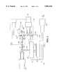
- FIG. 1is a schematic representation of a liquid delivery and chemical vapor deposition system, illustrating various features of the invention, in an illustrative embodiment thereof.
- FIG. 2Ais a portion of cross sectional view of a heater assembly usefully employed in a liquid delivery system, according to another aspect of the invention.
- FIG. 2Bis an exploded isometric view of a portion of FIG. 2A.
- FIG. 3is a graph of percent incorporation efficiency, of the liquid delivery and chemical vapor deposition system of FIG. 1, as a function of manifold tube diameter in inches.
- FIG. 4is a schematic representation of a portion of another liquid delivery vaporization apparatus, which may be usefully employed in a liquid delivery and chemical vapor deposition system of the type shown in FIG. 1.
- FIG. 5is a cross sectional view of another vaporizer design according to a further embodiment of the invention.
- FIG. 1is a schematic representation of a liquid delivery and chemical vapor deposition system, illustrating various features of the invention, in an illustrative embodiment thereof.
- the liquid delivery and chemical vapor deposition system 100comprises a vaporization zone 110 including a vaporizer chamber 130 of elongate conformation.
- the vaporizer chamber 130contains a vaporization frit element 120 fed by vertical flow conduit 122 with precursor source reagent from reagent supply vessel 112 connected to flow conduit 122 by supply line 114.
- the vaporizer chamber 130may also feature a carrier fluid inlet line 128 receiving carrier fluid such as argon, oxygen, or other carrier medium, from carrier fluid supply vessel 124 connected to inlet line 128 by supply line 126.
- carrier fluidsuch as argon, oxygen, or other carrier medium
- This carrier fluidmay be preheated to the vaporization temperature by means of a heater device. Preheating the carrier gas has been found to decrease particulate formation in the vaporization of Ta(OEt) 5 and to increase liquid flow capability in the vaporization of Cupra SelectTM copper source reagent.
- the vaporizer chamber 130 immediately downstream of the vaporization frit element 120is coupled in flow communication with manifold conduit 137.
- the manifold conduit 137comprises an upwardly inclined inlet portion 138 and a downstream horizontal portion 140.
- the downstream horizontal portion 140 of manifold conduit 137is joined by high conductance valve 152 to main feed conduit 142.
- the main feed conduit 142in turn is joined in discharge relationship to showerhead disperser 146 in chemical vapor deposition process chamber 144, as shown.
- the showerhead disperser 146may be constructed as more fully shown in U.S. patent application Ser. No. 08/402,142 and U.S. patent application Ser. No. 08/621,088, the disclosures of which are hereby incorporated herein in their entirety.
- the showerhead disperser 146is positioned in CVD chamber 144 in facing relationship to the susceptor 148 having wafer 150 thereon.
- the showerhead disperser 146has a series of orifices on its front face (not shown) through which the volatilized source reagent vapor is passed in the direction indicated by arrow A, for impingement on the wafer surface to effect deposition of desired species thereon.
- the CVD chamber 144is joined to exhaust manifold 156 for discharge of vapor therefrom under the action of vacuum pump 158, for final discharge of the vapor to the exhaust line 160, and transfer to effluent treatment means and/or final disposition.
- vaporizer chamber 130The lower end of vaporizer chamber 130 is joined by high conductance valve 132 to high conductance manifold bypass line 134 which drains liquid by gravity into the non-volatile residue trap 136 while passing the gas, depleted in non-volatile residue, in gas bypass line 154 to the aforementioned exhaust manifold 156.
- the upwardly inclined inlet portion 138 of manifold conduit 137thus serves to prevent non-volatile material from being passed by the manifold conduit 137 to the main feed inlet conduit 142 and thence into the CVD process chamber 144. Accordingly, any liquid or flowable solid decomposition product, deriving from decomposition of the source reagent components which have been vaporized by the vaporization element, are prevented by the upwardly inclined conduit from flow-through to the CVD chamber, and instead flow into the collection receptacle of the non-volatile residue trap 136.
- the collection receptacle for the non-volatile residuemay be sized and arranged to receive decomposition products from the vaporizer chamber for an extended period of time, whereby a cold trap receptacle may be a disposable part of the system, or alternatively such receptacle may be processed to remove the accumulated residue therefrom, followed by reinstallation and reuse of the receptacle in the system.
- the undecomposed reagent that has condensed in the cold trapmay optionally be reclaimed and purified for use in the deposition process, to achieve high levels of reagent utilization.
- vaporization efficiencyis favored by the use of high conductance flow conduits, manifolds and valves.
- relatively larger diameter flow passagesare desired for the flow conduits in the system, preferably on the order of 1/2 to 3/4 inch outer diameter, although it will be recognized that the size and conductance characteristics of the flow conduits may be widely varied in the broad practice of the present invention, as may the dimensions and conductance characteristics of the valves and manifolds employed in the practice of the invention.
- a manifoldmay be employed which is constructed of tubing and associated valves each having an inner diameter of from about 0.3 to about 3.0 inches, for high fluid flow conductance through the manifold.
- Optimal dimensional and operating characteristics of the flow conduits, valves and manifoldsmay be readily determined in a specific application of the invention, by the simple expedient of varying the conductance of the valves and flow passages, and measuring the incorporation efficiency of the source reagent species and/or the amount of decomposition byproduct produced, and from such performance data selecting the appropriate components and their flow and dimensional characteristics.
- in situ cleaningmay be carried out by flowing a cleaning medium through the vaporizer chamber and in cleaning contact with the vaporizer element and interior surfaces thereof.
- This in-situ cleaningmay be effected by providing a supply vessel of the cleaning medium, e.g., in alternative supply relationship to the supply line 114, as for example by a suitable valved manifoldjoined to the source reagent supply vessel 112 and cleaning medium supply vessel.
- the feeding of source reagent to supply line 114may be terminated and the feeding of cleaning medium may be initiated, and subsequently carried out for sufficient time and under sufficient process conditions to effect removal of the decomposition products from the vaporizer chamber, as well as from other interior surfaces of the piping, valves and manifolds of the system.
- Such in-situ cleaningmay for example comprise feeding of a liquid or other fluid cleaning medium through the vaporizer chamber in contact with the vaporization element therein.
- the cleaning mediummay for example comprise ammonia, alkanols, glycols, ethers, hydrocarbon solvents, halocarbon solvents, etc.
- Preferred liquidsinclude alkanolic solvents, tetraglyme, ammonia, and chlorinated hydrocarbon solvents.
- An additional enhancement of the liquid delivery and CVD system 100includes the use of electropolishing techniques for the interior walls of carrier fluid inlet line 128, vaporization chamber 130, manifold conduit 137, bypass line 134, and vertical flow conduit 122, wherein the inlet line 128, vaporization chamber 130, manifold conduit 137, bypass line 134, and vertical flow conduit 122 are preferably formed of a stainless steel material.
- a surface that is polished and passivated by electropolishinghas a lower sticking coefficient for precursors and also inhibits condensation of reagent on the tubing walls. If the sticking coefficient of the tubing walls is reduced, there is less likelihood of material sticking to the hot walls of the tubing.
- electropolished wall surfaces in an illustrative process systemhad no visible accumulation of material. Those lines not electropolished, however, had a thin, brown, powdery coating on the tubing walls. Electropolishing of the interior surfaces of carrier fluid inlet line 128, vaporization chamber 130, manifold conduit 137, bypass line 134, and vertical flow conduit 122 thereby is usefully employed to extend vaporizer lifetime by decreasing the formation of non-volatile species.
- the liquid delivery and CVD system 100may also be provided with vaporizer heating means, such as electrical resistance heaters, stream tracing lines, heating jackets, an encompassing convention oven, or other suitable heating means, by which the carrier fluid inlet line 128, vaporization chamber 130, manifold conduit 137, and high conductance manifold bypass line 134 are heated to prevent condensation of any vapor flowing therethrough.
- Vertical flow conduit 122could also be heated by vaporizer heating means.
- Positioned proximate to carrier fluid inlet line 128is a first vaporizer heating means 161.
- Positioned proximate to the vaporization chamber 130is a second vaporizer heating means 162.
- Positioned proximate to the manifold conduit 137is a third vaporizer heating means 164.
- a fourth vaporizer heating means 166Positioned proximate to the high conductance manifold bypass line 134 is a fourth vaporizer heating means 166.
- each vaporizer heating meanswill be referred to as heating coils, although each vaporizer heating means may comprise any of a wide variety of heating systems known to the skilled artisan for transferring thermal energy (to the internal passages of the carrier fluid inlet line 128, the vaporization chamber 130, the manifold conduit 137, and the high conductance manifold bypass line 134).
- a thermal jacket 168may also accommodate a length of carrier fluid inlet line 128, vaporization chamber 130, manifold conduit 137, high conductance manifold bypass line 134, residue trap 136, gas bypass line 154, and heating means 161, 162, and 166.
- the thermal jacket 168provides insulating properties to the elements accommodated therein and cooperates with the vaporizer heating means to raise the internal temperature of conduit 137 and bypass line 134.
- thermal jacket 168could be a vaporizer enclosed in an convention oven or other heating chamber. Oven side walls could define an enclosure or box surrounding the vaporizer. The oven would then be heated to prevent the condensation mentioned hereinearlier.
- FIGS. 2A and 2Billustrate a particularly advantageous vaporizer heating means.
- the vaporizer heating means shownis a cast aluminum heater surrounding the conduits, vaporization chamber, bypass lines, or the valves of the vaporizer. Electrical resistance heating elements are embedded in each heater.
- Each heateris designed to create and maintain an isothermal operating condition surrounding the conduits, vaporization chamber and bypass lines of the vaporizer. This in turn provides an isothermal condition at all boundary surfaces of the conduits, vaporization chamber and bypass lines to which the reagent is exposed.
- Each aluminum heaterincorporates a double spherical joint for good thermal contact between respective heaters. Since the desired isothermal operating condition is typically in the range of 200°-300° C., the cast aluminum heater of FIGS. 2A and 2B eliminates the heat lost at the junctions of more typical heating devices.
- FIG. 2Ais a portion of a cross-sectional view of cast aluminum heater assembly 200 used to heat a vaporization chamber (not shown).
- the heater assembly 200includes a body comprising first and second body half-sections, with first body half-section 202 shown in this drawing.
- First body half-section 202 and second body half-section (not shown)encase valve 206 in a clam-shell arrangement.
- Valve 206is one of two valves used to control the flow of vapor or fluids through the vaporizer apparatus and into a CVD reactor.
- Heater 208includes at least one embedded heating element 210.
- Clamp meanssuch as strap bands, hose clamps, welds, spring steel clips, adhesives, or threaded fasteners may be provided to clamp first and second body half-sections together.
- the clamp means hereafter describedwill be spherical hose clamp 212, although it is to be recognized that each clamp means may comprise any clamping system known to the skilled artisan for retaining sections of structural assemblies together as a conjoint or unitary structure.
- Joint meanssuch as tab and keyway structures, threaded fasteners, clips, bands, or welds may be provided to join or couple first and second body halves with heater 208.
- the joint meanswill be described in reference to a ball and socket spherical joint 214, although it is to be recognized that each joint means may comprise any suitable joining elements, members or systems known to the skilled artisan, for securing heater 208 to the body halve-sections and transferring thermal energy to each body half-section.
- FIG. 2Bis an exploded isometric view of the body half-sections of FIG. 2A.
- First body half-section 202 and second body half-section 216are shaped as shown in FIG. 2A and 2B.
- Spherical clamp 212(only a portion of which is shown) secures body half-section.
- Cap 218accommodates vertical flow conduit (not shown) for flowing precursor source reagent, and the cap, preferably constructed of aluminum or other suitable fabrication material, completes an enclosure of the vaporization chamber (not shown).
- the heater assembly as described with reference to FIGS. 2A and 2Bis used to maintain an isothermal condition for a vaporization chamber, the skilled artisan will recognize that the heater assembly may be easily adapted to other components of a liquid delivery system. Since the first and second heater half-sections are cast from aluminum, a mold could easily be fabricated to produce body half-sections for encasing the manifold, conduits, trap, or any other components of FIG. 1.
- the heater assembly as described with reference to FIGS. 2A and 2Bhas several advantages. Since aluminum is a good thermal conductor, thermal gradients are easily prevented and a uniform temperature is easier to achieve. Aluminum is relatively inexpensive to cast into complicated shapes. Since the aluminum heater assembly surrounds the stainless steel components preferably employed, the stainless steel components are heated by a combination of radiation from the aluminum, by conduction at the locations where the stainless steel and aluminum contact, and by convection through the air gap between the aluminum body half-sections and the stainless steel components. The aluminum heater body is advantageously spring-loaded against the stainless steel vaporization tubing at suitable locations by "spring plungers" embedded in hole 211. By this arrangement of spring plungers, the aluminum jacket is forced into intimate thermal contact with the stainless steel conduit at these locations.
- FIG. 3is a graph of percent incorporation efficiency as a function of manifold tube diameter in inches, showing the effect of conductance of flow passage means in the practice of the invention, for a system of the type schematically shown in FIG. 1.
- the conductance characteristics of flow passages in conduits, valves, and manifolds in the liquid delivery and vaporization system of the inventionmay be selectively varied to minimize the occurrence of decomposition of precursor source reagents in the vaporization step, and to maximize the incorporation efficiency of the deposited species in the film being formed on the substrate.
- the incorporation efficiency data reflected in FIG. 3were developed in a process system of the type schematically shown in FIG. 1, as used for chemical vapor deposition formation of illustrative Ba 0 .70 Sr 0 .30 TiO 3 (BST) thin films on 6" diameter wafers in the CVD chamber of the process system.
- BSTTiO 3
- a 40 micron fritmay be used to substantially enhance conductance, e.g., by a factor of two or more relative to previously used frit elements of smaller pore size. Since the pores of the 40 micron frit are larger than such previously used frit elements, the pores exhibit a longer time before clogging from accumulated non-volatile material.
- a larger pore size frite.g., a 40 micron pore size frit element
- a frit with a smaller pore sizee.g., 10-20 micron pore size
- a pore size which may be highly resistant to clogging and occlusionmay be less efficient for wetting and vaporization.
- the optimum pore size of a porous frit vaporizer elementmay be readily determined as the pore size accommodating the vaporizing and maintenance requirements of the overall system.
- FIG. 4shows a schematic representation of a portion of a liquid delivery vaporization system according to a further aspect of the invention.
- the liquid delivery vaporization system 400 shown in FIG. 4comprises a flow circuit including valves 402, 404, 406 and 408 and associated piping.
- the pipingincludes vapor flow conduit 410 coupling conduits 412 and 414 therewith.
- a valve 402is disposed in vapor flow conduit 410, which in turn is coupled to vapor feed conduit 420 for transport of the source reagent vapor to the chemical vapor deposition reactor (not shown).
- the vapor flow conduit 410comprises a sloped wall surface 416, forming a corresponding interior lip 424 as illustrated in the partially broken away view of vapor flow conduit 410.
- This interior lip structurethus serves as a dam or physical barrier means for preventing liquid from entering vapor feed conduit 420 and passing to the chemical vapor deposition reactor in operation of the overall system.
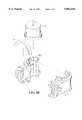
- FIG. 5is a cross sectional view of another vaporizer design.
- This vaporizer designincorporates various vaporizer components into a single, replaceable, and compact vaporizer cap unit.
- the vaporizer cap unit 500includes vaporization frit element 502 fed by capillary tube 504 flowing precursor source reagent from a suitable reagent supply (not shown).
- Vaporizer cap unit 500may also feature carrier gas delivery tube 506 receiving carrier gas from carrier fluid supply (not shown).
- Carrier gas passageway 508is coupled in gas flow communication with carrier gas delivery tube 506 and flows carrier gas to carrier gas nozzle 510.
- Nozzle 510induces turbulent flow in the carrier gas and restricts the flow of carrier gas in order to preheat carrier gas before injection into vaporization zone 512.
- Vaporizer cap unit 500may also include retaining means, such as snap ring, split ring, weld, locking tab, keyway, or press fit design by which the vaporization frit element 502 is retained in the vaporizer cap unit.
- retaining meanssuch as snap ring, split ring, weld, locking tab, keyway, or press fit design by which the vaporization frit element 502 is retained in the vaporizer cap unit.
- the retaining meanswill be described with reference to snap ring 514, although the retaining means may include any other suitable retaining means known to the skilled artisan, for fastening the frit 502 to vaporizer cap unit 500.
- Vaporizer cap unit 500includes an elongate outer body removably engageable with a vaporization chamber (not shown).
- the elongate outer bodydefines a longitudinal axis and a cross-section transverse to the longitudinal axis.
- the outer bodyincludes engaging means, such as threads, snap rings, or tab and keyway by which the outer body is removably engaged in the vaporization chamber.
- the engaging meanswill be described with reference to the male threaded portion 516, although the engaging means may include any other suitable engaging means known to the skilled artisan, for removably engaging the outer body to a vaporization chamber.
- An outer wall 517circumscribes first inner wall 518 and second inner wall 520.
- First inner wall 518circumscribes capillary tube 504 to define a first gas flow passageway 522 therebetween.
- First gas flow passageway 522is in fluid flow communication with bellows 523 and allows vacuum from the chemical vapor deposition reactor, e.g., as described in FIG. 1, to create a pressure differential in the bellows. Since the bellows 523 is subjected to a vacuum, the force of atmospheric pressure will compress the bellows and allow capillary tube outlet 524 to be appropriately positioned to frit 502.
- bellows 523is able to allow capillary tube outlet 524 to be raised from the frit to aid in removing clogs in the capillary tube.
- Nozzle 510may also include a circumferential slot to consistently seat the capillary tube 504.
- the first inner wall 518also acts to guide capillary tube 504 into vaporization cap unit 500.
- Second inner wall 520circumscribes first inner wall 518 to define a thermal isolation chamber 526.
- First gas flow passageway 522 and thermal isolation chamber 526cooperate to provide thermal isolation for capillary tube 504. Since the capillary tube 504 is in close proximity to heated frit 502, passageway 522 and isolation chamber 526 cooperate to maintain the temperature of capillary tube 504 below 200° C.
- a zero dead volume compression fitting 528 at an upper end of capillary tube 504removably engages with liquid precursor delivery tube 530 employed for flowing precursor source reagent from a reagent supply (not shown).
- Bellows 523is attached between compression fitting 528 and second inner wall 520 to form a gas-tight seal therebetween.
- An optional additional enhancement of the vaporizer cap unit 300may include, as discussed hereinearlier, the use of electropolishing techniques to yield a passivated surface with a lower sticking coefficient for the precursors and to inhibit condensation of reagent on the interior walls and reduce the likelihood of material sticking to the hot walls. Electropolishing the interior surfaces of capillary tube 304, first inner wall 518, carrier gas delivery tube 506, passageway 522, and each surface of second inner wall 520 enhances vaporizer lifetime by decreasing the formation of non-volatile species.
- the vaporizer cap unit 500may also be embodied with other features which improve the functionality and lifetime of the vaporizer.
- the bellows and the annular reservoirsprovide thermal isolation between the hot vaporizer body and the capillary tube 504.
- the thermal isolation provided by bellows 523 and annular reservoirs 522 and 526keeps the capillary tube 504 cool. If the capillary tube is also used to flow cleaning medium for in-situ cleaning, as discussed hereinearlier, a cooler capillary tube also helps prevent solid precursor deposits, by minimizing premature boiling of the cleaning medium.
- the nozzle 510concentrates hot gases and improves vaporization.
- the nozzleconcentrates heated gas flow to the point where the liquid precursor is discharged from capillary tube outlet 524. Since the primary mode of heat transfer to the frit 504 is from the carrier gas, concentrating the hot carrier gas in this capillary tube outlet zone will significantly improve vaporization.
- the vaporizer cap unit 500may also advantageously be constructed of commercially available components.
- Male threaded portion 516, first inner wall 518, and second inner wall 520may advantageously be respectively constructed of a 3/4 inch male VCR weld fitting, a 1/2 inch stainless steel tube, and a 3/4 inch stainless steel tube.
- Bellows 523may be constructed of a short length of 1/4 inch thick-walled bellows material.
- the zero dead volume compression fitting 528may be a 1/4 inch VCR weld fitting.
- the vaporizer cap unit 500embodies an improved vaporizer design which is highly manufacturable and readily utilized. Such unit can be easily integrated with existing CVD installations. The vaporizer cap unit 500 also affords the ability to increase wafer throughput and decrease vaporizer downtime in operation of the liquid delivery system and associated vapor deposition reactor.
- liquid delivery system and associated means and structuremay be formed of any suitable materials of construction that are advantageous in the manufacture, assembly, operation and maintenance thereof.
Landscapes
- Chemical & Material Sciences (AREA)
- General Chemical & Material Sciences (AREA)
- Chemical Kinetics & Catalysis (AREA)
- Engineering & Computer Science (AREA)
- Materials Engineering (AREA)
- Mechanical Engineering (AREA)
- Metallurgy (AREA)
- Organic Chemistry (AREA)
- Chemical Vapour Deposition (AREA)
Abstract
Description
Claims (38)
Priority Applications (5)
| Application Number | Priority Date | Filing Date | Title |
|---|---|---|---|
| US08/878,616US5882416A (en) | 1997-06-19 | 1997-06-19 | Liquid delivery system, heater apparatus for liquid delivery system, and vaporizer |
| PCT/US1998/012539WO1998058096A1 (en) | 1997-06-19 | 1998-06-17 | Liquid delivery system, heater apparatus for liquid delivery system, and vaporizer |
| AU80734/98AAU8073498A (en) | 1997-06-19 | 1998-06-17 | Liquid delivery system, heater apparatus for liquid delivery system, and vaporizer |
| KR1019997011955AKR100328356B1 (en) | 1997-06-19 | 1998-06-17 | Liquid delivery system, heater apparatus for liquid delivery system, and vaporizer |
| JP50469899AJP2002504191A (en) | 1997-06-19 | 1998-06-17 | Liquid supply system, heating device and vaporizer for liquid supply system |
Applications Claiming Priority (1)
| Application Number | Priority Date | Filing Date | Title |
|---|---|---|---|
| US08/878,616US5882416A (en) | 1997-06-19 | 1997-06-19 | Liquid delivery system, heater apparatus for liquid delivery system, and vaporizer |
Publications (1)
| Publication Number | Publication Date |
|---|---|
| US5882416Atrue US5882416A (en) | 1999-03-16 |
Family
ID=25372411
Family Applications (1)
| Application Number | Title | Priority Date | Filing Date |
|---|---|---|---|
| US08/878,616Expired - LifetimeUS5882416A (en) | 1997-06-19 | 1997-06-19 | Liquid delivery system, heater apparatus for liquid delivery system, and vaporizer |
Country Status (5)
| Country | Link |
|---|---|
| US (1) | US5882416A (en) |
| JP (1) | JP2002504191A (en) |
| KR (1) | KR100328356B1 (en) |
| AU (1) | AU8073498A (en) |
| WO (1) | WO1998058096A1 (en) |
Cited By (64)
| Publication number | Priority date | Publication date | Assignee | Title |
|---|---|---|---|---|
| US6012647A (en)* | 1997-12-01 | 2000-01-11 | 3M Innovative Properties Company | Apparatus and method of atomizing and vaporizing |
| US6037241A (en)* | 1998-02-19 | 2000-03-14 | First Solar, Llc | Apparatus and method for depositing a semiconductor material |
| US6045864A (en)* | 1997-12-01 | 2000-04-04 | 3M Innovative Properties Company | Vapor coating method |
| US6082714A (en)* | 1997-09-11 | 2000-07-04 | Applied Materials, Inc. | Vaporization apparatus and process |
| US6178925B1 (en)* | 1999-09-29 | 2001-01-30 | Advanced Technology Materials, Inc. | Burst pulse cleaning method and apparatus for liquid delivery system |
| US6216708B1 (en)* | 1998-07-23 | 2001-04-17 | Micron Technology, Inc. | On-line cleaning method for CVD vaporizers |
| US6244575B1 (en)* | 1996-10-02 | 2001-06-12 | Micron Technology, Inc. | Method and apparatus for vaporizing liquid precursors and system for using same |
| US6271498B1 (en)* | 1997-06-23 | 2001-08-07 | Nissin Electric Co., Ltd | Apparatus for vaporizing liquid raw material and method of cleaning CVD apparatus |
| US6280793B1 (en) | 1996-11-20 | 2001-08-28 | Micron Technology, Inc. | Electrostatic method and apparatus for vaporizing precursors and system for using same |
| US6318381B1 (en)* | 1999-07-13 | 2001-11-20 | Micron Technology, Inc. | Methods of cleaning vaporization surfaces |
| US6349887B1 (en) | 1998-12-30 | 2002-02-26 | Hyundai Electronics Industries Co., Ltd. | Liquid delivery system |
| KR100331024B1 (en)* | 2000-06-05 | 2002-04-03 | 김상호 | Liquid source injection vaporizer |
| US6527865B1 (en) | 1997-09-11 | 2003-03-04 | Applied Materials, Inc. | Temperature controlled gas feedthrough |
| US20030054099A1 (en)* | 2000-02-16 | 2003-03-20 | Holger Jurgensen | Condensation coating process |
| US6540840B1 (en)* | 1999-01-22 | 2003-04-01 | Kabushiki Kaisha Watanabe Shoko | Vaporizer for MOCVD and method of vaporizing raw material solutions for MOCVD |
| US6548112B1 (en)* | 1999-11-18 | 2003-04-15 | Tokyo Electron Limited | Apparatus and method for delivery of precursor vapor from low vapor pressure liquid sources to a CVD chamber |
| US20030084848A1 (en)* | 2001-06-22 | 2003-05-08 | Tokyo Electron Limited | Gas temperature control for a plasma process |
| US6635114B2 (en) | 1999-12-17 | 2003-10-21 | Applied Material, Inc. | High temperature filter for CVD apparatus |
| US6637212B2 (en) | 2001-04-27 | 2003-10-28 | Matheson Tri-Gas | Method and apparatus for the delivery of liquefied gases having constant impurity levels |
| US20030222360A1 (en)* | 2002-05-29 | 2003-12-04 | Randive Rajul V. | High throughput vaporizer |
| US20030228240A1 (en)* | 2002-06-10 | 2003-12-11 | Dwyer James L. | Nozzle for matrix deposition |
| US20040062862A1 (en)* | 2002-09-28 | 2004-04-01 | Ahn Seong Deok | Method and apparatus using large-area organic vapor deposition for formation of organic thin films or organic devices |
| US20040079286A1 (en)* | 2002-07-12 | 2004-04-29 | Sven Lindfors | Method and apparatus for the pulse-wise supply of a vaporized liquid reactant |
| US20040108068A1 (en)* | 2000-05-17 | 2004-06-10 | Shigeru Senzaki | Processing device and method of maintaining the device, mechanism and method for assembling processing device part, and lock mechanism and method for locking the lock mechanism |
| US20040113289A1 (en)* | 2001-01-18 | 2004-06-17 | Masayuki Toda | Carburetor, various types of devices using the carburetor, and method of vaporization |
| US20040234031A1 (en)* | 2003-04-16 | 2004-11-25 | Tom Francke | Dual-energy scanning-based detection of ionizing radiation |
| US20050109281A1 (en)* | 2002-03-22 | 2005-05-26 | Holger Jurgensen | Process for coating a substrate, and apparatus for carrying out the process |
| US20050250348A1 (en)* | 2004-05-06 | 2005-11-10 | Applied Materials, Inc. | In-situ oxide capping after CVD low k deposition |
| US20060032440A1 (en)* | 2004-08-11 | 2006-02-16 | Nolan James F | Apparatus and method for depositing a material on a substrate |
| US20060115590A1 (en)* | 2004-11-29 | 2006-06-01 | Tokyo Electron Limited; International Business Machines Corporation | Method and system for performing in-situ cleaning of a deposition system |
| US20060144338A1 (en)* | 2004-12-30 | 2006-07-06 | Msp Corporaton | High accuracy vapor generation and delivery for thin film deposition |
| US7090727B2 (en) | 2001-08-17 | 2006-08-15 | Micron Technology, Inc. | Heated gas line body feedthrough for vapor and gas delivery systems and methods for employing same |
| US20060222777A1 (en)* | 2005-04-05 | 2006-10-05 | General Electric Company | Method for applying a plasma sprayed coating using liquid injection |
| US20060222768A1 (en)* | 2005-03-31 | 2006-10-05 | Tokyo Electron Limited | Method and system for precursor delivery |
| US20060257295A1 (en)* | 2002-07-17 | 2006-11-16 | Ling Chen | Apparatus and method for generating a chemical precursor |
| US20060276054A1 (en)* | 2005-06-03 | 2006-12-07 | Applied Materials, Inc. | In situ oxide cap layer development |
| US20070057234A1 (en)* | 2005-09-12 | 2007-03-15 | Fujifilm Electronic Materials U.S.A., Inc. | Additives to prevent degradation of cyclic alkene derivatives |
| US20070057235A1 (en)* | 2005-09-12 | 2007-03-15 | Fujifilm Electronic Materials U.S.A., Inc. | Additives to prevent degradation of cyclic alkene derivatives |
| US20070098891A1 (en)* | 2005-10-31 | 2007-05-03 | Eastman Kodak Company | Vapor deposition apparatus and method |
| US20070181703A1 (en)* | 2006-02-07 | 2007-08-09 | Daryl Buchanan | System and method for producing and delivering vapor |
| US20070210260A1 (en)* | 2003-12-12 | 2007-09-13 | Horsky Thomas N | Method And Apparatus For Extending Equipment Uptime In Ion Implantation |
| US20070266944A1 (en)* | 2004-01-28 | 2007-11-22 | Tokyo Electron Limited | Film Forming Apparatus and Vaporizer |
| US20080073559A1 (en)* | 2003-12-12 | 2008-03-27 | Horsky Thomas N | Controlling the flow of vapors sublimated from solids |
| US20080149031A1 (en)* | 2006-03-30 | 2008-06-26 | Applied Materials, Inc. | Ampoule with a thermally conductive coating |
| US20080223409A1 (en)* | 2003-12-12 | 2008-09-18 | Horsky Thomas N | Method and apparatus for extending equipment uptime in ion implantation |
| US20080302302A1 (en)* | 2006-01-24 | 2008-12-11 | Hitachi Kokusai Electric Inc. | Substrate Processing System |
| US20090081874A1 (en)* | 2007-09-21 | 2009-03-26 | Cook Kevin S | Method for extending equipment uptime in ion implantation |
| US20090114157A1 (en)* | 2005-10-07 | 2009-05-07 | Wei Ti Lee | Ampoule splash guard apparatus |
| US20090154909A1 (en)* | 2005-10-06 | 2009-06-18 | Pascal Meyer | Liquid-heating device for electric household appliance |
| US20090291210A1 (en)* | 2005-09-12 | 2009-11-26 | Fujifilm Electronic Materials U.S.A., Inc. | Additives to Prevent Degradation of Cyclic Alkene Derivatives |
| US20090314370A1 (en)* | 2006-03-30 | 2009-12-24 | Norman Nakashima | Chemical delivery apparatus for cvd or ald |
| EP2141141A1 (en) | 2008-05-28 | 2010-01-06 | Air Products and Chemicals, Inc. | Improved Process Stability of NBDE Using Substituted Phenol Stabilizers |
| US20100112215A1 (en)* | 2008-10-31 | 2010-05-06 | Applied Materials, Inc. | Chemical precursor ampoule for vapor deposition processes |
| US20110019984A1 (en)* | 2008-01-21 | 2011-01-27 | Brian Howard Glover | Conduit for a condensation removal pump |
| US20110197816A1 (en)* | 2005-09-09 | 2011-08-18 | Lintec Co., Ltd. | Method for vaporizing liquid material capable of vaporizing liquid material at low temperature and vaporizer using the same |
| US20110286728A1 (en)* | 2010-05-24 | 2011-11-24 | Xiotin Industry Ltd. | Heater and electric instant water heater |
| US20160016192A1 (en)* | 2014-07-15 | 2016-01-21 | Seoul Semiconductor Co., Ltd. | Apparatus for manufacturing wavelength conversion part and method of manufacturing wavelength conversion part using the same |
| US20160341190A1 (en)* | 2015-05-21 | 2016-11-24 | Lg Electronics | Linear compressor |
| US20210066070A1 (en)* | 2019-08-27 | 2021-03-04 | Albert-Ludwigs-Universität Freiburg | Method and apparatus for manufacturing a semiconductor layer and substrate provided therewith |
| US20210071301A1 (en)* | 2019-09-10 | 2021-03-11 | Asm Ip Holding B.V. | Fill vessels and connectors for chemical sublimators |
| US20210364176A1 (en)* | 2018-02-12 | 2021-11-25 | Noritake Co., Limited | Liquid atomizing apparatus |
| CN114318300A (en)* | 2021-12-30 | 2022-04-12 | 拓荆科技股份有限公司 | Semiconductor processing equipment and reaction chamber and process pipeline cavity penetrating module thereof |
| US11634812B2 (en) | 2018-08-16 | 2023-04-25 | Asm Ip Holding B.V. | Solid source sublimator |
| US11712490B2 (en)* | 2017-04-25 | 2023-08-01 | Plasmapp Co., Ltd. | Sterilization apparatus |
Families Citing this family (3)
| Publication number | Priority date | Publication date | Assignee | Title |
|---|---|---|---|---|
| US6296711B1 (en) | 1998-04-14 | 2001-10-02 | Cvd Systems, Inc. | Film processing system |
| US6136725A (en)* | 1998-04-14 | 2000-10-24 | Cvd Systems, Inc. | Method for chemical vapor deposition of a material on a substrate |
| US6800568B1 (en) | 2002-07-02 | 2004-10-05 | Advanced Micro Devices, Inc. | Methods for the deposition of high-K films and high-K films produced thereby |
Citations (40)
| Publication number | Priority date | Publication date | Assignee | Title |
|---|---|---|---|---|
| US476274A (en)* | 1892-06-07 | Apparatus for purifying | ||
| DE370473C (en)* | 1923-03-03 | Karl Imfeld Dipl Ing | Device for vaporizing small amounts of liquid | |
| US2490547A (en)* | 1943-07-06 | 1949-12-06 | Vapor Rapid A G | Method of and apparatus for evaporating liquids |
| US2622184A (en)* | 1948-12-03 | 1952-12-16 | Johneas Paul | Steam generator |
| US2801322A (en)* | 1955-12-27 | 1957-07-30 | American Mach & Foundry | Decomposition chamber for monopropellant fuel |
| US2925329A (en)* | 1956-11-28 | 1960-02-16 | Garrett Corp | Gas generator |
| US3404873A (en)* | 1965-10-23 | 1968-10-08 | Sidney R. Orens | Humidifying and moisture diffusing attachment for motor vehicle heaters |
| US3520416A (en)* | 1968-02-12 | 1970-07-14 | Pall Corp | Liquid and gas-permeable microporous materials and process for making the same |
| US3549412A (en)* | 1968-04-29 | 1970-12-22 | Ethyl Corp | Metal plating particulated substrates |
| US3659402A (en)* | 1970-03-30 | 1972-05-02 | Howard Alliger | Multiple screen construction |
| US3823926A (en)* | 1971-04-23 | 1974-07-16 | Nu Air Humidifier Corp | Humidifier |
| US3943330A (en)* | 1973-02-26 | 1976-03-09 | United Kingdom Atomic Energy Authority | Method and apparatus for electrically heating a fluid |
| US3969449A (en)* | 1972-03-29 | 1976-07-13 | Imperial Chemical Industries Limited | Vaporizing process |
| US4036915A (en)* | 1973-01-02 | 1977-07-19 | Meloy Laboratories, Inc. | Temperature-controlled apparatus for fluid permeation or the like |
| US4288396A (en)* | 1978-11-17 | 1981-09-08 | Ottestad Nils T | Method and device for conditioning of breathing air for divers |
| EP0058571A1 (en)* | 1981-02-18 | 1982-08-25 | National Research Development Corporation | Method and apparatus for delivering a controlled flow rate of reactant to a vapour deposition process |
| JPS58125633A (en)* | 1982-01-18 | 1983-07-26 | Nippon Telegr & Teleph Corp <Ntt> | Gas feeding method in preparation of glass soot |
| US4529427A (en)* | 1977-05-19 | 1985-07-16 | At&T Bell Laboratories | Method for making low-loss optical waveguides on an industrial scale |
| US4673122A (en)* | 1986-05-22 | 1987-06-16 | Dubey Thomas W | Method and apparatus for repairing copper pipes |
| US4842893A (en)* | 1983-12-19 | 1989-06-27 | Spectrum Control, Inc. | High speed process for coating substrates |
| US4847469A (en)* | 1987-07-15 | 1989-07-11 | The Boc Group, Inc. | Controlled flow vaporizer |
| EP0328333A2 (en)* | 1988-02-10 | 1989-08-16 | Westinghouse Electric Corporation | Process for producing ceramic superconductors |
| US4883976A (en)* | 1987-12-02 | 1989-11-28 | Xicor, Inc. | Low power dual-mode CMOS bias voltage generator |
| JPH01305813A (en)* | 1988-06-01 | 1989-12-11 | Fujikura Ltd | Production of oxide-based superconductor |
| US5034372A (en)* | 1987-12-07 | 1991-07-23 | Mitsubishi Denki Kabushiki Kaisha | Plasma based method for production of superconductive oxide layers |
| US5097800A (en)* | 1983-12-19 | 1992-03-24 | Spectrum Control, Inc. | High speed apparatus for forming capacitors |
| US5110622A (en)* | 1988-04-21 | 1992-05-05 | Matsushita Electric Industrial Co., Ltd. | Process for preparing a metal sulfide thin film |
| US5120703A (en)* | 1990-04-17 | 1992-06-09 | Alfred University | Process for preparing oxide superconducting films by radio-frequency generated aerosol-plasma deposition in atmosphere |
| US5139999A (en)* | 1990-03-08 | 1992-08-18 | President And Fellows Of Harvard College | Chemical vapor deposition process where an alkaline earth metal organic precursor material is volatilized in the presence of an amine or ammonia and deposited onto a substrate |
| US5165960A (en)* | 1991-07-29 | 1992-11-24 | Ford Motor Company | Deposition of magnesium fluoride films |
| US5186120A (en)* | 1989-03-22 | 1993-02-16 | Mitsubishi Denki Kabushiki Kaisha | Mixture thin film forming apparatus |
| US5204314A (en)* | 1990-07-06 | 1993-04-20 | Advanced Technology Materials, Inc. | Method for delivering an involatile reagent in vapor form to a CVD reactor |
| US5225561A (en)* | 1990-07-06 | 1993-07-06 | Advanced Technology Materials, Inc. | Source reagent compounds for MOCVD of refractory films containing group IIA elements |
| US5259995A (en)* | 1991-10-30 | 1993-11-09 | Liquid Carbonic Industries Corporation | Vapor pressure device |
| US5362328A (en)* | 1990-07-06 | 1994-11-08 | Advanced Technology Materials, Inc. | Apparatus and method for delivering reagents in vapor form to a CVD reactor, incorporating a cleaning subsystem |
| US5376409A (en)* | 1992-12-21 | 1994-12-27 | The Research Foundation Of State University Of New York | Process and apparatus for the use of solid precursor sources in liquid form for vapor deposition of materials |
| US5434388A (en)* | 1992-10-07 | 1995-07-18 | E.G.O. Elektro-Gerate Blanc U. Fischer | Electrical heater for media, particularly flow heater |
| US5653806A (en)* | 1995-03-10 | 1997-08-05 | Advanced Technology Materials, Inc. | Showerhead-type discharge assembly for delivery of source reagent vapor to a substrate, and CVD process utilizing same |
| US5711816A (en)* | 1990-07-06 | 1998-01-27 | Advanced Technolgy Materials, Inc. | Source reagent liquid delivery apparatus, and chemical vapor deposition system comprising same |
| US5741363A (en)* | 1996-03-22 | 1998-04-21 | Advanced Technology Materials, Inc. | Interiorly partitioned vapor injector for delivery of source reagent vapor mixtures for chemical vapor deposition |
- 1997
- 1997-06-19USUS08/878,616patent/US5882416A/ennot_activeExpired - Lifetime
- 1998
- 1998-06-17KRKR1019997011955Apatent/KR100328356B1/ennot_activeExpired - Fee Related
- 1998-06-17AUAU80734/98Apatent/AU8073498A/ennot_activeAbandoned
- 1998-06-17WOPCT/US1998/012539patent/WO1998058096A1/enactiveIP Right Grant
- 1998-06-17JPJP50469899Apatent/JP2002504191A/ennot_activeCeased
Patent Citations (42)
| Publication number | Priority date | Publication date | Assignee | Title |
|---|---|---|---|---|
| US476274A (en)* | 1892-06-07 | Apparatus for purifying | ||
| DE370473C (en)* | 1923-03-03 | Karl Imfeld Dipl Ing | Device for vaporizing small amounts of liquid | |
| US2490547A (en)* | 1943-07-06 | 1949-12-06 | Vapor Rapid A G | Method of and apparatus for evaporating liquids |
| US2622184A (en)* | 1948-12-03 | 1952-12-16 | Johneas Paul | Steam generator |
| US2801322A (en)* | 1955-12-27 | 1957-07-30 | American Mach & Foundry | Decomposition chamber for monopropellant fuel |
| US2925329A (en)* | 1956-11-28 | 1960-02-16 | Garrett Corp | Gas generator |
| US3404873A (en)* | 1965-10-23 | 1968-10-08 | Sidney R. Orens | Humidifying and moisture diffusing attachment for motor vehicle heaters |
| US3520416A (en)* | 1968-02-12 | 1970-07-14 | Pall Corp | Liquid and gas-permeable microporous materials and process for making the same |
| US3549412A (en)* | 1968-04-29 | 1970-12-22 | Ethyl Corp | Metal plating particulated substrates |
| US3659402A (en)* | 1970-03-30 | 1972-05-02 | Howard Alliger | Multiple screen construction |
| US3823926A (en)* | 1971-04-23 | 1974-07-16 | Nu Air Humidifier Corp | Humidifier |
| US3969449A (en)* | 1972-03-29 | 1976-07-13 | Imperial Chemical Industries Limited | Vaporizing process |
| US4036915A (en)* | 1973-01-02 | 1977-07-19 | Meloy Laboratories, Inc. | Temperature-controlled apparatus for fluid permeation or the like |
| US3943330A (en)* | 1973-02-26 | 1976-03-09 | United Kingdom Atomic Energy Authority | Method and apparatus for electrically heating a fluid |
| US4529427A (en)* | 1977-05-19 | 1985-07-16 | At&T Bell Laboratories | Method for making low-loss optical waveguides on an industrial scale |
| US4288396A (en)* | 1978-11-17 | 1981-09-08 | Ottestad Nils T | Method and device for conditioning of breathing air for divers |
| EP0058571A1 (en)* | 1981-02-18 | 1982-08-25 | National Research Development Corporation | Method and apparatus for delivering a controlled flow rate of reactant to a vapour deposition process |
| JPS58125633A (en)* | 1982-01-18 | 1983-07-26 | Nippon Telegr & Teleph Corp <Ntt> | Gas feeding method in preparation of glass soot |
| US4842893A (en)* | 1983-12-19 | 1989-06-27 | Spectrum Control, Inc. | High speed process for coating substrates |
| US5097800A (en)* | 1983-12-19 | 1992-03-24 | Spectrum Control, Inc. | High speed apparatus for forming capacitors |
| US4673122A (en)* | 1986-05-22 | 1987-06-16 | Dubey Thomas W | Method and apparatus for repairing copper pipes |
| US4847469A (en)* | 1987-07-15 | 1989-07-11 | The Boc Group, Inc. | Controlled flow vaporizer |
| US4883976A (en)* | 1987-12-02 | 1989-11-28 | Xicor, Inc. | Low power dual-mode CMOS bias voltage generator |
| US5034372A (en)* | 1987-12-07 | 1991-07-23 | Mitsubishi Denki Kabushiki Kaisha | Plasma based method for production of superconductive oxide layers |
| EP0328333A2 (en)* | 1988-02-10 | 1989-08-16 | Westinghouse Electric Corporation | Process for producing ceramic superconductors |
| US5110622A (en)* | 1988-04-21 | 1992-05-05 | Matsushita Electric Industrial Co., Ltd. | Process for preparing a metal sulfide thin film |
| JPH01305813A (en)* | 1988-06-01 | 1989-12-11 | Fujikura Ltd | Production of oxide-based superconductor |
| US5186120A (en)* | 1989-03-22 | 1993-02-16 | Mitsubishi Denki Kabushiki Kaisha | Mixture thin film forming apparatus |
| US5139999A (en)* | 1990-03-08 | 1992-08-18 | President And Fellows Of Harvard College | Chemical vapor deposition process where an alkaline earth metal organic precursor material is volatilized in the presence of an amine or ammonia and deposited onto a substrate |
| US5120703A (en)* | 1990-04-17 | 1992-06-09 | Alfred University | Process for preparing oxide superconducting films by radio-frequency generated aerosol-plasma deposition in atmosphere |
| US5225561A (en)* | 1990-07-06 | 1993-07-06 | Advanced Technology Materials, Inc. | Source reagent compounds for MOCVD of refractory films containing group IIA elements |
| US5204314A (en)* | 1990-07-06 | 1993-04-20 | Advanced Technology Materials, Inc. | Method for delivering an involatile reagent in vapor form to a CVD reactor |
| US5362328A (en)* | 1990-07-06 | 1994-11-08 | Advanced Technology Materials, Inc. | Apparatus and method for delivering reagents in vapor form to a CVD reactor, incorporating a cleaning subsystem |
| US5536323A (en)* | 1990-07-06 | 1996-07-16 | Advanced Technology Materials, Inc. | Apparatus for flash vaporization delivery of reagents |
| US5711816A (en)* | 1990-07-06 | 1998-01-27 | Advanced Technolgy Materials, Inc. | Source reagent liquid delivery apparatus, and chemical vapor deposition system comprising same |
| US5165960A (en)* | 1991-07-29 | 1992-11-24 | Ford Motor Company | Deposition of magnesium fluoride films |
| US5259995A (en)* | 1991-10-30 | 1993-11-09 | Liquid Carbonic Industries Corporation | Vapor pressure device |
| US5434388A (en)* | 1992-10-07 | 1995-07-18 | E.G.O. Elektro-Gerate Blanc U. Fischer | Electrical heater for media, particularly flow heater |
| US5376409A (en)* | 1992-12-21 | 1994-12-27 | The Research Foundation Of State University Of New York | Process and apparatus for the use of solid precursor sources in liquid form for vapor deposition of materials |
| US5376409B1 (en)* | 1992-12-21 | 1997-06-03 | Univ New York State Res Found | Process and apparatus for the use of solid precursor sources in liquid form for vapor deposition of materials |
| US5653806A (en)* | 1995-03-10 | 1997-08-05 | Advanced Technology Materials, Inc. | Showerhead-type discharge assembly for delivery of source reagent vapor to a substrate, and CVD process utilizing same |
| US5741363A (en)* | 1996-03-22 | 1998-04-21 | Advanced Technology Materials, Inc. | Interiorly partitioned vapor injector for delivery of source reagent vapor mixtures for chemical vapor deposition |
Non-Patent Citations (32)
| Title |
|---|
| "Direct Liquid Injection Sub-System--DLI-25B," Bulletin DLI-Dec. 1994, copyright 1994, MKS Instruments, Inc. |
| "Integrated Systems Approach Based on DLI," Bulletin LPDS-Dec. 1994, copyright 1994, MKS Instruments, Inc. |
| Direct Liquid Injection Sub System DLI 25B, Bulletin DLI Dec. 1994, copyright 1994, MKS Instruments, Inc.* |
| Erbil, A., et al., "A Review of Metalorganic Chemical Vapor Deposition of High-Temperature Superconducting Thin Films," SPIE vol. 1187 Processing of Films for High Tc Superconducting Electronics (1989), 104-109. |
| Erbil, A., et al., A Review of Metalorganic Chemical Vapor Deposition of High Temperature Superconducting Thin Films, SPIE vol. 1187 Processing of Films for High Tc Superconducting Electronics (1989), 104 109.* |
| Gardiner, R., et al., "Volatile Barium β-Diketonate Polyether Adducts. Synthesis, Characterization, and Metallorganic Chemical vapor Deposition," Chem. Mater., 3(6), 1991, pp. 1053-1059. |
| Gardiner, R., et al., Volatile Barium Diketonate Polyether Adducts. Synthesis, Characterization, and Metallorganic Chemical vapor Deposition, Chem. Mater., 3(6), 1991, pp. 1053 1059.* |
| Hiskes, R., et al., "Single source metalorganic chemical vapor deposition of low microwave surface resistance YBa2 Cu3 O7," Appl. Phys. Lett. 59(5), 29 Jul. 1991, pp. 606-607. |
| Hiskes, R., et al., Single source metalorganic chemical vapor deposition of low microwave surface resistance YBa 2 Cu 3 O 7 , Appl. Phys. Lett. 59(5), 29 Jul. 1991, pp. 606 607.* |
| Integrated Systems Approach Based on DLI, Bulletin LPDS Dec. 1994, copyright 1994, MKS Instruments, Inc.* |
| Kirlin, Peter S., et al., "Growth of high Tc YBaCuO thin films by metalorganic chemical vapor deposition," SPIE vol. 1187 Processing of Films for High Tc Superconducting Electronics (1989), 115-127. |
| Kirlin, Peter S., et al., Growth of high Tc YBaCuO thin films by metalorganic chemical vapor deposition, SPIE vol. 1187 Processing of Films for High Tc Superconducting Electronics (1989), 115 127.* |
| Lackey, W.J., et al., "Rapid chemical vapor deposition of superconducting YBa2 Cu3 Ox," Appl. Phys. Lett. 56(12), 19 Mar. 1990, pp. 1175-1177. |
| Lackey, W.J., et al., Rapid chemical vapor deposition of superconducting YBa 2 Cu 3 O x , Appl. Phys. Lett. 56(12), 19 Mar. 1990, pp. 1175 1177.* |
| Panson, A.J., et al., "Chemical vapor deposition of YBa2 Cu3 O7 using metalorganic chelate precursors," Appl. Phys. Lett. 53(18), 31 Oct. 1988, pp. 1756-1757. |
| Panson, A.J., et al., Chemical vapor deposition of YBa 2 Cu 3 O 7 using metalorganic chelate precursors, Appl. Phys. Lett. 53(18), 31 Oct. 1988, pp. 1756 1757.* |
| Scarsbrook, G., et al., "Low temperature pulsed plasma deposition. Part I-a new technique for thin film dposition with complete gas dissociation," Vacuum, 38(8-10), 1988, pp. 627-631. |
| Scarsbrook, G., et al., Low temperature pulsed plasma deposition. Part I a new technique for thin film dposition with complete gas dissociation, Vacuum, 38(8 10), 1988, pp. 627 631.* |
| Singh, R.K., et al., "In situ processing of eptiaxial Y-Ba-Cu-O high Tc superconducting films on (100) SrTiO3 and (100) YS-ZrO2 substrates at 500-650° C," App. Phys. Lett. 54(22), 29 May 1989, pp. 2271-2273. |
| Singh, R.K., et al., In situ processing of eptiaxial Y Ba Cu O high Tc superconducting films on (100) SrTiO 3 and (100) YS ZrO 2 substrates at 500 650 C, App. Phys. Lett. 54(22), 29 May 1989, pp. 2271 2273.* |
| Turnipseed, S.B., et al., "Synthesis and Characterization of Alkaline-Earth-Metal β-Diketonate Complexes Used as Precursors for Chemical Vapor Deposition of Thin-Film Superconductors," Inorg. Chem. 1991, 30(6), 1164-1170. |
| Turnipseed, S.B., et al., Synthesis and Characterization of Alkaline Earth Metal Diketonate Complexes Used as Precursors for Chemical Vapor Deposition of Thin Film Superconductors, Inorg. Chem. 1991, 30(6), 1164 1170.* |
| Van Buskirk, P., et al., "MOCVD Growth of BaTiO3 in an 8" Single-Wafer CVD Reactor," Proceedings of ISAF92, in press (1992), 3 pages. |
| Van Buskirk, P., et al., MOCVD Growth of BaTiO 3 in an 8 Single Wafer CVD Reactor, Proceedings of ISAF92, in press (1992), 3 pages.* |
| Yoshitake, T., et al., "As-grown superconducting Bi-Sr-Ca-Cu-O thin films by coevaporation," App. Phys. Lett. 55(7), 14 Aug. 1989, pp. 702-704. |
| Yoshitake, T., et al., As grown superconducting Bi Sr Ca Cu O thin films by coevaporation, App. Phys. Lett. 55(7), 14 Aug. 1989, pp. 702 704.* |
| Zama, H., et al., "Properties of Metalorganic Precursors for Chemical Vapor Deposition of Oxide Superconductors," Japanese Journal of Applied Physics, 29(7), Jul. 1990, pp. L1072-L1074. |
| Zama, H., et al., Properties of Metalorganic Precursors for Chemical Vapor Deposition of Oxide Superconductors, Japanese Journal of Applied Physics, 29(7), Jul. 1990, pp. L1072 L1074.* |
| Zhang, J., et al., "Plasma Enhanced Metalorganic Chemical Vapor Deposition of Conductive Oxide Electrodes for Ferroelectric BaTiO3 Capacitors," Mat. Res. Soc. Symp. Proc., vol. 310, 1993, pp. 249-254. |
| Zhang, J., et al., "Single liquid source plasma-enhanced metalorganic chemical vapor deposition of high quality YBa2 Cu3 O7-x thin films," Appl. Phys. Lett. 61(24), 14 Dec. 1992, pp. 2884-2886. |
| Zhang, J., et al., Plasma Enhanced Metalorganic Chemical Vapor Deposition of Conductive Oxide Electrodes for Ferroelectric BaTiO 3 Capacitors, Mat. Res. Soc. Symp. Proc., vol. 310, 1993, pp. 249 254.* |
| Zhang, J., et al., Single liquid source plasma enhanced metalorganic chemical vapor deposition of high quality YBa 2 Cu 3 O 7 x thin films, Appl. Phys. Lett. 61(24), 14 Dec. 1992, pp. 2884 2886.* |
Cited By (128)
| Publication number | Priority date | Publication date | Assignee | Title |
|---|---|---|---|---|
| US6244575B1 (en)* | 1996-10-02 | 2001-06-12 | Micron Technology, Inc. | Method and apparatus for vaporizing liquid precursors and system for using same |
| US6402126B2 (en) | 1996-10-02 | 2002-06-11 | Micron Technology, Inc. | Method and apparatus for vaporizing liquid precursors and system for using same |
| US6280793B1 (en) | 1996-11-20 | 2001-08-28 | Micron Technology, Inc. | Electrostatic method and apparatus for vaporizing precursors and system for using same |
| US6271498B1 (en)* | 1997-06-23 | 2001-08-07 | Nissin Electric Co., Ltd | Apparatus for vaporizing liquid raw material and method of cleaning CVD apparatus |
| US6258170B1 (en)* | 1997-09-11 | 2001-07-10 | Applied Materials, Inc. | Vaporization and deposition apparatus |
| US6082714A (en)* | 1997-09-11 | 2000-07-04 | Applied Materials, Inc. | Vaporization apparatus and process |
| US6527865B1 (en) | 1997-09-11 | 2003-03-04 | Applied Materials, Inc. | Temperature controlled gas feedthrough |
| US6245150B1 (en) | 1997-12-01 | 2001-06-12 | 3M Innovative Properties Company | Vapor coating apparatus |
| US6012647A (en)* | 1997-12-01 | 2000-01-11 | 3M Innovative Properties Company | Apparatus and method of atomizing and vaporizing |
| US6045864A (en)* | 1997-12-01 | 2000-04-04 | 3M Innovative Properties Company | Vapor coating method |
| US6037241A (en)* | 1998-02-19 | 2000-03-14 | First Solar, Llc | Apparatus and method for depositing a semiconductor material |
| US6216708B1 (en)* | 1998-07-23 | 2001-04-17 | Micron Technology, Inc. | On-line cleaning method for CVD vaporizers |
| US6258171B1 (en) | 1998-07-23 | 2001-07-10 | Micron Technology, Inc. | Direct liquid injection system with on-line cleaning |
| US6349887B1 (en) | 1998-12-30 | 2002-02-26 | Hyundai Electronics Industries Co., Ltd. | Liquid delivery system |
| US7744698B2 (en) | 1999-01-22 | 2010-06-29 | Kabushiki Kaisha Watanabe Shoko | Vaporizer for MOCVD and method of vaporizing raw material solutions for MOCVD |
| US20030221625A1 (en)* | 1999-01-22 | 2003-12-04 | Masayuki Toda | Vaporizer for MOCVD and method of vaporizing raw material solutions for MOCVD |
| US6931203B2 (en) | 1999-01-22 | 2005-08-16 | Kabushiki Kaisha Motoyama Seisakusho | Vaporizer for MOCVD and method of vaporizing raw material solutions for MOCVD |
| US6540840B1 (en)* | 1999-01-22 | 2003-04-01 | Kabushiki Kaisha Watanabe Shoko | Vaporizer for MOCVD and method of vaporizing raw material solutions for MOCVD |
| US20040020437A1 (en)* | 1999-01-22 | 2004-02-05 | Masayuki Toda | Vaporizer for MOCVD and method of vaporizing raw material solutions for MOCVD |
| US6419994B1 (en) | 1999-07-13 | 2002-07-16 | Micron Technology, Inc. | Methods of chemical vapor deposition |
| US6318381B1 (en)* | 1999-07-13 | 2001-11-20 | Micron Technology, Inc. | Methods of cleaning vaporization surfaces |
| US6796313B2 (en) | 1999-07-13 | 2004-09-28 | Micron Technology, Inc. | Methods of cleaning vaporization surfaces |
| US6626999B1 (en) | 1999-07-13 | 2003-09-30 | Micron Technology, Inc. | Vapor forming devices |
| US6178925B1 (en)* | 1999-09-29 | 2001-01-30 | Advanced Technology Materials, Inc. | Burst pulse cleaning method and apparatus for liquid delivery system |
| US6548112B1 (en)* | 1999-11-18 | 2003-04-15 | Tokyo Electron Limited | Apparatus and method for delivery of precursor vapor from low vapor pressure liquid sources to a CVD chamber |
| US6635114B2 (en) | 1999-12-17 | 2003-10-21 | Applied Material, Inc. | High temperature filter for CVD apparatus |
| US7201942B2 (en)* | 2000-02-16 | 2007-04-10 | Aixtron Ag | Coating method |
| US20030054099A1 (en)* | 2000-02-16 | 2003-03-20 | Holger Jurgensen | Condensation coating process |
| US6899786B2 (en)* | 2000-05-17 | 2005-05-31 | Tokyo Electron Limited | Processing device and method of maintaining the device, mechanism and method for assembling processing device part, and lock mechanism and method for locking the lock mechanism |
| US7481903B2 (en) | 2000-05-17 | 2009-01-27 | Tokyo Electron Limited | Processing device and method of maintaining the device, mechanism and method for assembling processing device parts, and lock mechanism and method for locking the lock mechanism |
| US20040108068A1 (en)* | 2000-05-17 | 2004-06-10 | Shigeru Senzaki | Processing device and method of maintaining the device, mechanism and method for assembling processing device part, and lock mechanism and method for locking the lock mechanism |
| US20050150456A1 (en)* | 2000-05-17 | 2005-07-14 | Tokyo Electron Limited | Processing device and method of maintaining the device, mechanism and method for assembling processing device parts, and lock mechanism and method for locking the lock mechanism |
| KR100331024B1 (en)* | 2000-06-05 | 2002-04-03 | 김상호 | Liquid source injection vaporizer |
| US7246796B2 (en)* | 2001-01-18 | 2007-07-24 | Masayuki Toda | Carburetor, various types of devices using the carburetor, and method of vaporization |
| US20040113289A1 (en)* | 2001-01-18 | 2004-06-17 | Masayuki Toda | Carburetor, various types of devices using the carburetor, and method of vaporization |
| US20080193645A1 (en)* | 2001-01-18 | 2008-08-14 | Masayuki Toda | Vaporizer and various devices using the same and an associated vaporizing method |
| US7673856B2 (en) | 2001-01-18 | 2010-03-09 | Kabushiki Kaisha Watanabe Shoko | Vaporizer and various devices using the same and an associated vaporizing method |
| US6637212B2 (en) | 2001-04-27 | 2003-10-28 | Matheson Tri-Gas | Method and apparatus for the delivery of liquefied gases having constant impurity levels |
| US20030084848A1 (en)* | 2001-06-22 | 2003-05-08 | Tokyo Electron Limited | Gas temperature control for a plasma process |
| US6811651B2 (en)* | 2001-06-22 | 2004-11-02 | Tokyo Electron Limited | Gas temperature control for a plasma process |
| US7531061B2 (en) | 2001-06-22 | 2009-05-12 | Tokyo Electron Limited | Gas temperature control for a plasma process |
| US20050028736A1 (en)* | 2001-06-22 | 2005-02-10 | Tokyo Electron Limited | Gas temperature control for a plasma process |
| US7090727B2 (en) | 2001-08-17 | 2006-08-15 | Micron Technology, Inc. | Heated gas line body feedthrough for vapor and gas delivery systems and methods for employing same |
| US20060207506A1 (en)* | 2001-08-17 | 2006-09-21 | Carpenter Craig M | Heated gas line body feedthrough for vapor and gas delivery systems and methods of employing same |
| US20050109281A1 (en)* | 2002-03-22 | 2005-05-26 | Holger Jurgensen | Process for coating a substrate, and apparatus for carrying out the process |
| US20030222360A1 (en)* | 2002-05-29 | 2003-12-04 | Randive Rajul V. | High throughput vaporizer |
| US6789789B2 (en) | 2002-05-29 | 2004-09-14 | Veeco Instruments Inc. | High throughput vaporizer |
| US20030228240A1 (en)* | 2002-06-10 | 2003-12-11 | Dwyer James L. | Nozzle for matrix deposition |
| US20040079286A1 (en)* | 2002-07-12 | 2004-04-29 | Sven Lindfors | Method and apparatus for the pulse-wise supply of a vaporized liquid reactant |
| US7588736B2 (en)* | 2002-07-17 | 2009-09-15 | Applied Materials, Inc. | Apparatus and method for generating a chemical precursor |
| US7569191B2 (en) | 2002-07-17 | 2009-08-04 | Applied Materials, Inc. | Method and apparatus for providing precursor gas to a processing chamber |
| US20090011129A1 (en)* | 2002-07-17 | 2009-01-08 | Seshadri Ganguli | Method and apparatus for providing precursor gas to a processing chamber |
| US20060257295A1 (en)* | 2002-07-17 | 2006-11-16 | Ling Chen | Apparatus and method for generating a chemical precursor |
| US20050287299A1 (en)* | 2002-09-28 | 2005-12-29 | Ahn Seong D | Method and apparatus using large-area organic vapor deposition for formation of organic thin films or organic devices |
| US20040062862A1 (en)* | 2002-09-28 | 2004-04-01 | Ahn Seong Deok | Method and apparatus using large-area organic vapor deposition for formation of organic thin films or organic devices |
| US7027561B2 (en) | 2003-04-16 | 2006-04-11 | Xcounter Ab | Dual-energy scanning-based detection of ionizing radiation |
| US20040234031A1 (en)* | 2003-04-16 | 2004-11-25 | Tom Francke | Dual-energy scanning-based detection of ionizing radiation |
| US20080047607A1 (en)* | 2003-12-12 | 2008-02-28 | Horsky Thomas N | Controlling The Flow Of Vapors Sublimated From Solids |
| US7820981B2 (en) | 2003-12-12 | 2010-10-26 | Semequip, Inc. | Method and apparatus for extending equipment uptime in ion implantation |
| US7723700B2 (en) | 2003-12-12 | 2010-05-25 | Semequip, Inc. | Controlling the flow of vapors sublimated from solids |
| US20080223409A1 (en)* | 2003-12-12 | 2008-09-18 | Horsky Thomas N | Method and apparatus for extending equipment uptime in ion implantation |
| US20070210260A1 (en)* | 2003-12-12 | 2007-09-13 | Horsky Thomas N | Method And Apparatus For Extending Equipment Uptime In Ion Implantation |
| US7629590B2 (en) | 2003-12-12 | 2009-12-08 | Semequip, Inc. | Method and apparatus for extending equipment uptime in ion implantation |
| US20070241689A1 (en)* | 2003-12-12 | 2007-10-18 | Horsky Thomas N | Method and apparatus for extending equipment uptime in ion implantation |
| US20080073559A1 (en)* | 2003-12-12 | 2008-03-27 | Horsky Thomas N | Controlling the flow of vapors sublimated from solids |
| US20070266944A1 (en)* | 2004-01-28 | 2007-11-22 | Tokyo Electron Limited | Film Forming Apparatus and Vaporizer |
| US20050250348A1 (en)* | 2004-05-06 | 2005-11-10 | Applied Materials, Inc. | In-situ oxide capping after CVD low k deposition |
| US7112541B2 (en) | 2004-05-06 | 2006-09-26 | Applied Materials, Inc. | In-situ oxide capping after CVD low k deposition |
| US7780787B2 (en) | 2004-08-11 | 2010-08-24 | First Solar, Inc. | Apparatus and method for depositing a material on a substrate |
| US20060032440A1 (en)* | 2004-08-11 | 2006-02-16 | Nolan James F | Apparatus and method for depositing a material on a substrate |
| US8758511B2 (en)* | 2004-08-13 | 2014-06-24 | Tokyo Electron Limited | Film forming apparatus and vaporizer |
| US20060115590A1 (en)* | 2004-11-29 | 2006-06-01 | Tokyo Electron Limited; International Business Machines Corporation | Method and system for performing in-situ cleaning of a deposition system |
| US20100203244A1 (en)* | 2004-12-30 | 2010-08-12 | Msp Corporation | High accuracy vapor generation and delivery for thin film deposition |
| US20060144338A1 (en)* | 2004-12-30 | 2006-07-06 | Msp Corporaton | High accuracy vapor generation and delivery for thin film deposition |
| US7485338B2 (en)* | 2005-03-31 | 2009-02-03 | Tokyo Electron Limited | Method for precursor delivery |
| US20060222768A1 (en)* | 2005-03-31 | 2006-10-05 | Tokyo Electron Limited | Method and system for precursor delivery |
| US20060222777A1 (en)* | 2005-04-05 | 2006-10-05 | General Electric Company | Method for applying a plasma sprayed coating using liquid injection |
| US20060276054A1 (en)* | 2005-06-03 | 2006-12-07 | Applied Materials, Inc. | In situ oxide cap layer development |
| US7273823B2 (en) | 2005-06-03 | 2007-09-25 | Applied Materials, Inc. | Situ oxide cap layer development |
| US20110197816A1 (en)* | 2005-09-09 | 2011-08-18 | Lintec Co., Ltd. | Method for vaporizing liquid material capable of vaporizing liquid material at low temperature and vaporizer using the same |
| US8162298B2 (en)* | 2005-09-09 | 2012-04-24 | Lintec Co., Ltd | Method for vaporizing liquid material capable of vaporizing liquid material at low temperature and vaporizer using the same |
| US20090291210A1 (en)* | 2005-09-12 | 2009-11-26 | Fujifilm Electronic Materials U.S.A., Inc. | Additives to Prevent Degradation of Cyclic Alkene Derivatives |
| US7931823B2 (en) | 2005-09-12 | 2011-04-26 | Fujifilm Electronic Materials U.S.A., Inc. | Additives to prevent degradation of cyclic alkene derivatives |
| US7883639B2 (en) | 2005-09-12 | 2011-02-08 | Fujifilm Electronic Materials, U.S.A., Inc. | Additives to prevent degradation of cyclic alkene derivatives |
| US7871536B2 (en) | 2005-09-12 | 2011-01-18 | Fujifilm Electronic Materials U.S.A., Inc. | Additives to prevent degradation of cyclic alkene derivatives |
| US7985350B2 (en) | 2005-09-12 | 2011-07-26 | Fujifilm Electronic Materials U.S.A., Inc. | Additives to prevent degradation of cyclic alkene derivatives |
| US8252704B2 (en) | 2005-09-12 | 2012-08-28 | Fujifilm Electronic Materials U.S.A., Inc. | Additives to prevent degradation of cyclic alkene derivatives |
| US20070057234A1 (en)* | 2005-09-12 | 2007-03-15 | Fujifilm Electronic Materials U.S.A., Inc. | Additives to prevent degradation of cyclic alkene derivatives |
| US20070057235A1 (en)* | 2005-09-12 | 2007-03-15 | Fujifilm Electronic Materials U.S.A., Inc. | Additives to prevent degradation of cyclic alkene derivatives |
| US20090154909A1 (en)* | 2005-10-06 | 2009-06-18 | Pascal Meyer | Liquid-heating device for electric household appliance |
| US20090114157A1 (en)* | 2005-10-07 | 2009-05-07 | Wei Ti Lee | Ampoule splash guard apparatus |
| US7699295B2 (en) | 2005-10-07 | 2010-04-20 | Applied Materials, Inc. | Ampoule splash guard apparatus |
| US20070098891A1 (en)* | 2005-10-31 | 2007-05-03 | Eastman Kodak Company | Vapor deposition apparatus and method |
| US8641829B2 (en)* | 2006-01-24 | 2014-02-04 | Hitachi Kokusai Electric Inc. | Substrate processing system |
| US8506714B2 (en)* | 2006-01-24 | 2013-08-13 | Hitachi Kokusai Electric Inc. | Substrate processing system |
| US20080302302A1 (en)* | 2006-01-24 | 2008-12-11 | Hitachi Kokusai Electric Inc. | Substrate Processing System |
| US20070181703A1 (en)* | 2006-02-07 | 2007-08-09 | Daryl Buchanan | System and method for producing and delivering vapor |
| US7680399B2 (en) | 2006-02-07 | 2010-03-16 | Brooks Instrument, Llc | System and method for producing and delivering vapor |
| US20090314370A1 (en)* | 2006-03-30 | 2009-12-24 | Norman Nakashima | Chemical delivery apparatus for cvd or ald |
| US20080149031A1 (en)* | 2006-03-30 | 2008-06-26 | Applied Materials, Inc. | Ampoule with a thermally conductive coating |
| US7748400B2 (en) | 2006-03-30 | 2010-07-06 | Applied Materials, Inc. | Chemical delivery apparatus for CVD or ALD |
| US8951478B2 (en) | 2006-03-30 | 2015-02-10 | Applied Materials, Inc. | Ampoule with a thermally conductive coating |
| US7832432B2 (en) | 2006-03-30 | 2010-11-16 | Applied Materials, Inc. | Chemical delivery apparatus for CVD or ALD |
| US7875125B2 (en) | 2007-09-21 | 2011-01-25 | Semequip, Inc. | Method for extending equipment uptime in ion implantation |
| US20090081874A1 (en)* | 2007-09-21 | 2009-03-26 | Cook Kevin S | Method for extending equipment uptime in ion implantation |
| US8798449B2 (en)* | 2008-01-21 | 2014-08-05 | Charles Austen Pumps Limited | Conduit for a condensation removal pump |
| US20110019984A1 (en)* | 2008-01-21 | 2011-01-27 | Brian Howard Glover | Conduit for a condensation removal pump |
| EP3141538A1 (en) | 2008-05-28 | 2017-03-15 | Air Products And Chemicals, Inc. | Improved process stability of nbde using substituted phenol stabilizers |
| US8173213B2 (en) | 2008-05-28 | 2012-05-08 | Air Products And Chemicals, Inc. | Process stability of NBDE using substituted phenol stabilizers |
| EP2141141A1 (en) | 2008-05-28 | 2010-01-06 | Air Products and Chemicals, Inc. | Improved Process Stability of NBDE Using Substituted Phenol Stabilizers |
| WO2010005937A1 (en) | 2008-07-08 | 2010-01-14 | Fujifilm Electronic Materials U.S.A., Inc. | Additives to prevent degradation of cyclic alkene derivatives |
| US8146896B2 (en) | 2008-10-31 | 2012-04-03 | Applied Materials, Inc. | Chemical precursor ampoule for vapor deposition processes |
| US20100112215A1 (en)* | 2008-10-31 | 2010-05-06 | Applied Materials, Inc. | Chemical precursor ampoule for vapor deposition processes |
| US20110286728A1 (en)* | 2010-05-24 | 2011-11-24 | Xiotin Industry Ltd. | Heater and electric instant water heater |
| US20160016192A1 (en)* | 2014-07-15 | 2016-01-21 | Seoul Semiconductor Co., Ltd. | Apparatus for manufacturing wavelength conversion part and method of manufacturing wavelength conversion part using the same |
| US10267302B2 (en)* | 2015-05-21 | 2019-04-23 | Lg Electronics Inc. | Linear compressor with suction guide |
| US20160341190A1 (en)* | 2015-05-21 | 2016-11-24 | Lg Electronics | Linear compressor |
| US11712490B2 (en)* | 2017-04-25 | 2023-08-01 | Plasmapp Co., Ltd. | Sterilization apparatus |
| US20210364176A1 (en)* | 2018-02-12 | 2021-11-25 | Noritake Co., Limited | Liquid atomizing apparatus |
| US12152807B2 (en)* | 2018-02-12 | 2024-11-26 | Noritake Co., Limited | Liquid atomizing apparatus |
| US11634812B2 (en) | 2018-08-16 | 2023-04-25 | Asm Ip Holding B.V. | Solid source sublimator |
| US11773486B2 (en) | 2018-08-16 | 2023-10-03 | Asm Ip Holding B.V. | Solid source sublimator |
| US11996287B2 (en)* | 2019-08-27 | 2024-05-28 | Albert-Ludwigs-Universität Freiburg | Method and apparatus for manufacturing a semiconductor layer and substrate provided therewith |
| US20210066070A1 (en)* | 2019-08-27 | 2021-03-04 | Albert-Ludwigs-Universität Freiburg | Method and apparatus for manufacturing a semiconductor layer and substrate provided therewith |
| US12394621B2 (en) | 2019-08-27 | 2025-08-19 | Albert-Ludwigs-Universität Freiburg | Method and apparatus for manufacturing a semiconductor layer and substrate provided therewith |
| US20210071301A1 (en)* | 2019-09-10 | 2021-03-11 | Asm Ip Holding B.V. | Fill vessels and connectors for chemical sublimators |
| CN114318300B (en)* | 2021-12-30 | 2024-05-10 | 拓荆科技股份有限公司 | Semiconductor processing equipment, reaction chamber thereof and process pipeline cavity penetrating module |
| CN114318300A (en)* | 2021-12-30 | 2022-04-12 | 拓荆科技股份有限公司 | Semiconductor processing equipment and reaction chamber and process pipeline cavity penetrating module thereof |
Also Published As
| Publication number | Publication date |
|---|---|
| KR100328356B1 (en) | 2002-03-13 |
| JP2002504191A (en) | 2002-02-05 |
| KR20010013933A (en) | 2001-02-26 |
| AU8073498A (en) | 1999-01-04 |
| WO1998058096A1 (en) | 1998-12-23 |
Similar Documents
| Publication | Publication Date | Title |
|---|---|---|
| US5882416A (en) | Liquid delivery system, heater apparatus for liquid delivery system, and vaporizer | |
| US5362328A (en) | Apparatus and method for delivering reagents in vapor form to a CVD reactor, incorporating a cleaning subsystem | |
| KR100366249B1 (en) | Liquid reaction source supply apparatus and chemical vapor deposition apparatus equipped with the apparatus | |
| US6210485B1 (en) | Chemical vapor deposition vaporizer | |
| US5919522A (en) | Growth of BaSrTiO3 using polyamine-based precursors | |
| KR100746433B1 (en) | High temperature filter | |
| US6096134A (en) | Liquid delivery system | |
| US8235364B2 (en) | Reagent dispensing apparatuses and delivery methods | |
| EP1508631B1 (en) | Method and apparatus for the delivery of precursor materials | |
| CN1966762B (en) | Carburetor, various types of devices using the carburetor, and method of vaporization | |
| JP3103596B2 (en) | Apparatus and method for supplying reagents in vapor form to a CVD reactor | |
| US20060125129A1 (en) | Vaporizer and apparatus for vaporizing and supplying | |
| EP1608005A1 (en) | Vaporizer, film forming apparatus including the same, method of vaporization and method of forming film | |
| EP1492160A1 (en) | Vaporizer, various devices using the same, and vaporizing method | |
| WO2001098556A2 (en) | Temperature controlled gas feedthrough | |
| EP1113089A1 (en) | MOCVD of lead zirconate titanate films | |
| WO1999004061A1 (en) | Liquid delivery system comprising upstream pressure control means |
Legal Events
| Date | Code | Title | Description |
|---|---|---|---|
| AS | Assignment | Owner name:ADVANCED TECHNOLOGY MATERIALS, INC., CONNECTICUT Free format text:ASSIGNMENT OF ASSIGNORS INTEREST;ASSIGNORS:VAN BUSKIRK, PETER C.;BILODEAU, STEVEN M.;CARL, RALPH J., JR.;REEL/FRAME:008918/0127;SIGNING DATES FROM 19980112 TO 19980114 | |
| STCF | Information on status: patent grant | Free format text:PATENTED CASE | |
| CC | Certificate of correction | ||
| FEPP | Fee payment procedure | Free format text:PAT HOLDER NO LONGER CLAIMS SMALL ENTITY STATUS, ENTITY STATUS SET TO UNDISCOUNTED (ORIGINAL EVENT CODE: STOL); ENTITY STATUS OF PATENT OWNER: LARGE ENTITY | |
| FPAY | Fee payment | Year of fee payment:4 | |
| FPAY | Fee payment | Year of fee payment:8 | |
| FEPP | Fee payment procedure | Free format text:PAYOR NUMBER ASSIGNED (ORIGINAL EVENT CODE: ASPN); ENTITY STATUS OF PATENT OWNER: LARGE ENTITY | |
| FPAY | Fee payment | Year of fee payment:12 | |
| AS | Assignment | Owner name:GOLDMAN SACHS BANK USA, AS COLLATERAL AGENT, NEW YORK Free format text:SECURITY INTEREST;ASSIGNORS:ENTEGRIS, INC.;POCO GRAPHITE, INC.;ATMI, INC.;AND OTHERS;REEL/FRAME:032815/0852 Effective date:20140430 Owner name:GOLDMAN SACHS BANK USA, AS COLLATERAL AGENT, NEW Y Free format text:SECURITY INTEREST;ASSIGNORS:ENTEGRIS, INC.;POCO GRAPHITE, INC.;ATMI, INC.;AND OTHERS;REEL/FRAME:032815/0852 Effective date:20140430 | |
| AS | Assignment | Owner name:GOLDMAN SACHS BANK USA, AS COLLATERAL AGENT, NEW YORK Free format text:SECURITY INTEREST;ASSIGNORS:ENTEGRIS, INC.;POCO GRAPHITE, INC.;ATMI, INC.;AND OTHERS;REEL/FRAME:032812/0192 Effective date:20140430 Owner name:GOLDMAN SACHS BANK USA, AS COLLATERAL AGENT, NEW Y Free format text:SECURITY INTEREST;ASSIGNORS:ENTEGRIS, INC.;POCO GRAPHITE, INC.;ATMI, INC.;AND OTHERS;REEL/FRAME:032812/0192 Effective date:20140430 | |
| AS | Assignment | Owner name:ENTEGRIS, INC., MASSACHUSETTS Free format text:ASSIGNMENT OF ASSIGNORS INTEREST;ASSIGNOR:ADVANCED TECHNOLOGY MATERIALS, INC.;REEL/FRAME:034894/0025 Effective date:20150204 | |
| AS | Assignment | Owner name:POCO GRAPHITE, INC., MASSACHUSETTS Free format text:RELEASE BY SECURED PARTY;ASSIGNOR:GOLDMAN SACHS BANK USA, AS COLLATERAL AGENT;REEL/FRAME:047477/0032 Effective date:20181106 Owner name:ATMI, INC., CONNECTICUT Free format text:RELEASE BY SECURED PARTY;ASSIGNOR:GOLDMAN SACHS BANK USA, AS COLLATERAL AGENT;REEL/FRAME:047477/0032 Effective date:20181106 Owner name:ENTEGRIS, INC., MASSACHUSETTS Free format text:RELEASE BY SECURED PARTY;ASSIGNOR:GOLDMAN SACHS BANK USA, AS COLLATERAL AGENT;REEL/FRAME:047477/0032 Effective date:20181106 Owner name:ADVANCED TECHNOLOGY MATERIALS, INC., CONNECTICUT Free format text:RELEASE BY SECURED PARTY;ASSIGNOR:GOLDMAN SACHS BANK USA, AS COLLATERAL AGENT;REEL/FRAME:047477/0032 Effective date:20181106 Owner name:ATMI PACKAGING, INC., CONNECTICUT Free format text:RELEASE BY SECURED PARTY;ASSIGNOR:GOLDMAN SACHS BANK USA, AS COLLATERAL AGENT;REEL/FRAME:047477/0032 Effective date:20181106 Owner name:POCO GRAPHITE, INC., MASSACHUSETTS Free format text:RELEASE BY SECURED PARTY;ASSIGNOR:GOLDMAN SACHS BANK USA, AS COLLATERAL AGENT;REEL/FRAME:047477/0151 Effective date:20181106 Owner name:ENTEGRIS, INC., MASSACHUSETTS Free format text:RELEASE BY SECURED PARTY;ASSIGNOR:GOLDMAN SACHS BANK USA, AS COLLATERAL AGENT;REEL/FRAME:047477/0151 Effective date:20181106 Owner name:ADVANCED TECHNOLOGY MATERIALS, INC., CONNECTICUT Free format text:RELEASE BY SECURED PARTY;ASSIGNOR:GOLDMAN SACHS BANK USA, AS COLLATERAL AGENT;REEL/FRAME:047477/0151 Effective date:20181106 Owner name:ATMI PACKAGING, INC., CONNECTICUT Free format text:RELEASE BY SECURED PARTY;ASSIGNOR:GOLDMAN SACHS BANK USA, AS COLLATERAL AGENT;REEL/FRAME:047477/0151 Effective date:20181106 Owner name:ATMI, INC., CONNECTICUT Free format text:RELEASE BY SECURED PARTY;ASSIGNOR:GOLDMAN SACHS BANK USA, AS COLLATERAL AGENT;REEL/FRAME:047477/0151 Effective date:20181106 |