US5882348A - Valved manifold - Google Patents
Valved manifoldDownload PDFInfo
- Publication number
- US5882348A US5882348AUS08/792,067US79206797AUS5882348AUS 5882348 AUS5882348 AUS 5882348AUS 79206797 AUS79206797 AUS 79206797AUS 5882348 AUS5882348 AUS 5882348A
- Authority
- US
- United States
- Prior art keywords
- stem
- port
- patient connection
- connection port
- patient
- Prior art date
- Legal status (The legal status is an assumption and is not a legal conclusion. Google has not performed a legal analysis and makes no representation as to the accuracy of the status listed.)
- Expired - Lifetime
Links
- 238000009423ventilationMethods0.000claimsabstractdescription30
- 230000037361pathwayEffects0.000claimsabstractdescription26
- 239000012530fluidSubstances0.000claimsdescription18
- 238000004891communicationMethods0.000claimsdescription16
- 238000007789sealingMethods0.000claimsdescription9
- 230000000694effectsEffects0.000claimsdescription8
- 238000002627tracheal intubationMethods0.000claimsdescription8
- 238000000034methodMethods0.000claimsdescription5
- 230000000903blocking effectEffects0.000claimsdescription4
- 244000273618Sphenoclea zeylanicaSpecies0.000abstractdescription2
- 239000007789gasSubstances0.000description11
- 238000006073displacement reactionMethods0.000description7
- 206010036790Productive coughDiseases0.000description3
- 239000003570airSubstances0.000description3
- 230000000712assemblyEffects0.000description3
- 238000000429assemblyMethods0.000description3
- 238000003780insertionMethods0.000description3
- 230000037431insertionEffects0.000description3
- 210000003802sputumAnatomy0.000description3
- 208000024794sputumDiseases0.000description3
- 230000008878couplingEffects0.000description2
- 238000010168coupling processMethods0.000description2
- 238000005859coupling reactionMethods0.000description2
- 238000010348incorporationMethods0.000description2
- 210000002345respiratory systemAnatomy0.000description2
- 230000001225therapeutic effectEffects0.000description2
- 239000012080ambient airSubstances0.000description1
- 230000004888barrier functionEffects0.000description1
- 230000004886head movementEffects0.000description1
- 230000002262irrigationEffects0.000description1
- 238000003973irrigationMethods0.000description1
- 230000007794irritationEffects0.000description1
- 238000002955isolationMethods0.000description1
- 239000000463materialSubstances0.000description1
- 230000013011matingEffects0.000description1
- 230000001681protective effectEffects0.000description1
- 230000001105regulatory effectEffects0.000description1
- 230000029058respiratory gaseous exchangeEffects0.000description1
- 239000007787solidSubstances0.000description1
Images

Classifications
- A—HUMAN NECESSITIES
- A61—MEDICAL OR VETERINARY SCIENCE; HYGIENE
- A61M—DEVICES FOR INTRODUCING MEDIA INTO, OR ONTO, THE BODY; DEVICES FOR TRANSDUCING BODY MEDIA OR FOR TAKING MEDIA FROM THE BODY; DEVICES FOR PRODUCING OR ENDING SLEEP OR STUPOR
- A61M16/00—Devices for influencing the respiratory system of patients by gas treatment, e.g. ventilators; Tracheal tubes
- A61M16/04—Tracheal tubes
- A61M16/0463—Tracheal tubes combined with suction tubes, catheters or the like; Outside connections
- A—HUMAN NECESSITIES
- A61—MEDICAL OR VETERINARY SCIENCE; HYGIENE
- A61M—DEVICES FOR INTRODUCING MEDIA INTO, OR ONTO, THE BODY; DEVICES FOR TRANSDUCING BODY MEDIA OR FOR TAKING MEDIA FROM THE BODY; DEVICES FOR PRODUCING OR ENDING SLEEP OR STUPOR
- A61M16/00—Devices for influencing the respiratory system of patients by gas treatment, e.g. ventilators; Tracheal tubes
- A61M16/08—Bellows; Connecting tubes ; Water traps; Patient circuits
- A61M16/0816—Joints or connectors
- A61M16/0825—Joints or connectors with ball-sockets
Definitions
- This inventionrelates generally to valved manifold devices, and is specifically directed to such devices in medical conduit systems. It provides a valved manifold particularly useful at the patient intubation interface of endotracheal ventilation/aspiration systems.
- manifold devicesfor directing fluid flow.
- manifold devicesfor directing fluid flow.
- the manifoldis often associated with other components as a system.
- closed systems for endotracheal suctioning and ventilatingtypically include a manifold enabling introduction of ventilating gases and intermittent exhalation of patient breath simultaneously with insertion and operation of a tracheal suctioning catheter.
- the manifold structuretypically includes multiple ports, usually the open ends of respective conduits extending from a common chamber. One such port is interfaced to a patient through a patient connection device.
- the suction catheteris often included within an assembly which is connectable to a second port of the manifold.
- the catheter assemblyconventionally includes a collapsible plastic envelope positioned to entirely surround the catheter. A practitioner manually externally collapses the envelope onto the external surface of the catheter and advances the catheter through the manifold into an access tube connected to a patient, retracting the catheter in a similar fashion following the aspiration procedure.
- the manifoldthus provides a first pathway for ventilation gases and a second pathway for the catheter.
- the catheterprovides isolation from the ventilating gases for fluids withdrawn from the patient through the manifold.
- the catheterWhen the catheter is withdrawn, it is often desired to continue regulated ventilation through the manifold.
- Previous efforts in this connectionhave involved the provision of auxiliary sealing structures for use in association with the manifold. These arrangements have had several disadvantages. Because they have not been integral with the manifold, their use has been inconvenient in practice.
- Manipulations, or other disturbances, of the catheter assemblytend to cause irritation to the patient and to impose strain on connection points within the assembly. These problems are alleviated to a considerable extent by the provision of a swivel capability (rotation about the longitudinal axis of the connection port) at the patient interface. Unfortunately, the provision of such a capability has heretofore involved the incorporation of swivel elements which are inordinately expensive and/or which provide an unreliable seal for the system.
- the '267 patentdiscloses a manifold and a multi-position stop cock valve.
- the valveis provided with a "Tee" shaped internal stem channel pattern so that the stem may be positioned selectively to wash the internal lumen of a catheter, to irrigate the patient or to accommodate travel of the catheter through the stem to suction the patient.
- the valvemay be plugged directly into an access port of the manifold. Patient ventilation is conducted without respect to the valve through other ports of the manifold.
- the valveitself constitutes an integral component of a catheter assembly and must be removed from the manifold with the remainder of that assembly.
- valvepositioned to minimize dead air space within the manifold and capable of passing a catheter.
- the valvemust provide a sealed gas flow path through the manifold in both its open and closed conditions with respect to catheter travel.
- the manifoldshould further be removable from any associated catheter assembly.
- the manifoldshould also include connection structure capable of providing a sealed passageway through a rotating or swiveling joint.
- the inventionmay be embodied as a multi-function manifold positioned at the distal end of a catheter assembly.
- a catheter tubeis slidable lengthwise through a passageway including ports at the proximal and distal sides of the manifold.
- a special valveis positioned within that passageway to minimize dead air space, and may be operated to open a travel path for the catheter through the manifold.
- the manifoldpreferably includes a patient connection conduit at its distal side for attachment to (and communication with) an indwelling intubation device, such as a tracheal tube, endotracheal tube or nasopharyngeal tube.
- the manifoldalso includes a ventilating structure extending radially from (and in fluid communication with) the passageway.
- the ventilating structureconstitutes means for selectively introducing ambient air, oxygenated air and other therapeutic gases into the respiratory system of the patient.
- Other conduitsmay also be provided for the introduction of therapeutic and diagnostic implements and for the introduction of other suitable gases
- the manifoldand in particular, the manifold valve, is structured and arranged to enable simultaneous patient ventilation and protected tracheal suctioning.
- a suctioning cathetermay be coupled at its proximal end to a suctioning valve. The distal end of the catheter may then be fed through a conduit at the proximal side of the manifold for reciprocal movement through the intubation device.
- the catheteris often provided in an assembly, whereby it is enveloped by a sterility-enhancing protective barrier, which is coupled to an access structure at the proximal side of the manifold.
- the manifold and valvemay be integral with the catheter assembly, but are preferably detachable to facilitate multiple uses of the manifold, either in association with other assemblies or for other applications.
- the manifold valveis structured and arranged as a stop cock with a specialized valve stem.
- the valve stemis fashioned to provide the previously described versatility of function to the manifold.
- the manifoldmay thus be positioned in a patient ventilating circuit in conventional fashion to function as a portion of that circuit.
- the valve stemis positioned to maintain a first, ventilating, flow path through the manifold, including through a portion of the stem.
- the stemblocks flow through other selected travel paths within the manifold.
- the passageway required for the catheter, when it is present,is sealed against gas flow by the stem.
- the stemmay be repositioned to permit passage of a catheter through a slot in the stem, while still maintaining the ventilation flow path in open condition.
- a preferred valved manifold assemblyincludes a stop cock valve with a hollow stem and a transverse slot arranged to permit the stem to be rotated between open and closed positions. In both positions, a ventilating pathway is maintained through the stem between ventilator and patient connection ports of the manifold. In open position, the stem provides a travel pathway for a catheter between the patient connection port and an access port of the manifold. In closed condition, the stem seals this travel pathway.
- This structureis ideally suited for inclusion in patient ventilation/aspiration systems.
- an interface assembly for closed system endotracheal ventilating and aspirating proceduresmay be embodied as a manifold having a ventilating port in open communication with an interior chamber, a patient connection port in open communication with the chamber and out of registration with the ventilation port and an access port in communication with the chamber and in registration with the patient connection port.
- the access port and patient connection portsare positioned to provide a catheter travel pathway through the access port, the chamber and the patient connection port.
- the assemblyfurther includes a valve comprising a valve stem positioned within the catheter travel pathway.
- the stemis constructed and arranged for movement between first and second positions. In the first position, the stem blocks the pathway. In the second position, the stem provides a portion of the catheter travel pathway.
- Actuation structureis linked to the stem and manually operable to move the stem between the first and second positions.
- the valveis further constructed and arranged to avoid blocking gas flow between the ventilation port and the patient connection port.
- the ventilation portis oriented generally transverse the catheter travel pathway.
- the valve stemis ideally positioned within the interior chamber and is structured with a hollow center cavity opening towards the ventilation port.
- the hollow centeris in open communication with the patient connection port, typically by means of a slot transverse the cavity and in registration with the patient connection port when the stem is in either the first or second position.
- the stemincludes a wall with an outer surface in sealing relationship with the access port when the stem is in the first position. An opening through the wall into the cavity is positioned and configured to register with the access port when the stem is in the second position.
- the manifold assemblyis interposed between an indwelling tube at the distal end of the manifold and a ventilating circuit.
- These junctionspreferably embody a swivel configuration to permit left or right bedside placement of the ventilation circuitry and free rotation of the ventilation circuit with patient head movement to reduce the risk of extubation.
- Copending Ser. No. 08/794,337identified in the internal files of the assignee and the attorney of record as Case No. 3097, describes an improved swivel connection apparatus which is generally useful for providing a gas-tight passageway between the interiors of discrete components of a fluid delivery system.
- the apparatusis structured and arranged to permit connection between tubular elements or conduits associated with such components.
- the connectorcomprises a pair of cooperating parts.
- the first such parttypically comprises a structural element carried by the manifold of the invention.
- This structural elementmay take a variety of forms, but in any case presents an approximately cylindrical interior surface, constituting the female portion of the connector.
- the second part of the connectorhas a hollow interior between first and second open ends.
- the first such endconstitutes the male portion of the connector. It includes an outer surface configured to register, in sliding seal relation, with the female portion of the connector. This outer surface is thus approximately cylindrical and is sized appropriately for insertion within the female portion.
- the distal end segment of the hollow cylinder(the male portion) is flared to an enlarged diameter so that it effects a self-biased engagement with the interior surface of the female portion across a relatively small surface area. In this fashion an effective gas seal is maintained with only a minor amount of frictional resistance against rotation of the male portion of the connector within the female portion of the connector.
- the flared segmentis usually of reduced wall thickness and somewhat more flexible than the remainder of the male portion. The seal created by mating of the female and male portions is effective when the pressure within the hollow center of the connector is either positive or negative with respect to ambient conditions, within the practical range normally encountered in medical applications.
- the second open end of the second part of the connectoris structured and arranged for coupling to an intubation fixture.
- a tubemay be press fit into an entry port opening in the second end of the second part to effect a mechanical connection. Rotation of the tube then effects equivalent rotation of the male portion within the female portion of the connector, thereby avoiding strain in the joint between the system components.
- a terminal segment of the second end of the second partmay further be structured cooperatively to form a journal bearing connection with the manifold. In this fashion, the first and second parts are supported against radial displacement or twist, which could interfere with smooth rotational displacement of these parts with respect to each other.
- approximately cylindrical male and female parts of the connectorare adapted to couple by a plug fit (either a snap fit or press fit) connection, and those parts are structured to permit relative rotational displacement while they are in coupled condition.
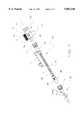
- FIG. 1is an exploded view substantially in cross section of a valved manifold of this invention
- FIG. 2is a substantially cross sectional view in elevation of the valved manifold of FIG. 1, in assembled condition;
- FIG. 3is an enlarged view in cross section of the connector portion of FIG. 1;
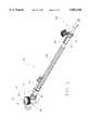
- FIG. 4is an exploded plan view, partially broken away, illustrating the manner in which the valved manifold of FIG. 1 may be connected in operable association with components of a suction catheter assembly;
- FIG. 5is a perspective view of the assembly of FIG. 4, in fully assembled condition and rotated to expose features not visible in FIG. 4.
- FIGS. 1 and 2illustrate a preferred embodiment in which an optional swivel connector, designated generally 20, is fabricated as a portion of a stop cock manifold valve, designated generally 22.
- the valve 22includes a knob 24, which may be turned by finger pressure to rotate a stem 26.
- the stem 26is structured with an open interior 28, defined by a continuous wall 32.
- the open bottom 36 of the open interior 28registers with a first manifold port 40.
- the stem 26may be rotated between a first, closed, position in which a solid portion 48 of the wall 32 is brought into registration with a second manifold port 46 and a second, open, position, as illustrated by FIGS. 1 and 2, wherein an opening 44 of the wall 32 registers with the second manifold port 46.
- a travel pathis opened between the second manifold port 46 and a third manifold port 50 through the open interior 28 of the stem 26.
- the port 46is sealed.
- a transverse slot 54 through the continuous wall 32provides a flow path between the port 50 and the open interior 28.
- the first manifold port 40remains in open, fluid flow communication with the third manifold port 50 through the open bottom 36 of the open, the stem interior 28 and the slot 54.
- the connector 20comprises a pair of cooperating female and male parts, designated generally 60 and 62, respectively.
- the female part 60is embodied as structure extending from the third manifold port 50.
- This structure 60constitutes a connection conduit typical of manifold devices 20 of the type illustrated, and presents an approximately cylindrical interior surface 64, constituting the female portion of the connector 20.
- the male part 62 of the connector 20has a hollow interior 66 between first 68 and second 70 open ends
- the first end 68constitutes the male portion of the connector. It includes an outer surface 74 configured to register, in sliding seal relation, with the female port 60 of the connector 20.
- This outer surface 74is thus approximately cylindrical, and is sized appropriately for insertion within the female port 60.
- a distal end segment 74is flared to an enlarged diameter so that it effects a self-biased engagement with the interior surface 64 of the female port 60 across an annular band of relatively small surface area.
- the flared segment 74is of significantly reduced wall thickness, tapering towards the first end 68.
- the second, open, end 70 of the male part 62 of the connector 20is structured and arranged for coupling to a system component, such as an intubation tube (not shown).
- a terminal segment 76 of the second end 70may further be structured cooperatively to form a journal bearing connection, designated generally 80 with structure 82 associated with the female part 60 of the connector 20, all as best shown by FIG. 3.
- the female 60 and second 62 partsare supported against radial displacement A--A or twist, which could interfere with smooth rotational displacement B--B of these parts with respect to each other.
- the structure 82is formed as an annular ring which is received within a corresponding annular groove 84 comprising the terminal segment 76.
- These elements 82, 84are structured and arranged to effect a fit snap fit connection which resists axial displacement C--C, but permits low resistance rotational displacement B--B, preferably over a full 360° range.
- the manifold valve 22is shown in association with a catheter assembly, designated generally 86.
- a suction control valve, generally 88is connected to the proximal end 90 of the assembly 86 by means of a luer collar 91 and wing connector 92.
- a suction catheter 93is carried within a flexible sheath 94, and may be selectively extended or withdrawn (by manual manipulation through the sheath) through a sputum trap 95, which is in turn connected by a luer collar 96 to the second manifold port 46 of the manifold 22.
- a swivel connector 80is carried by the third connection port conduit 50.
- first manifold port 40constitutes a ventilation port
- second manifold port 46constitutes an access port for apparatus such as a suction catheter
- third manifold port 50constitutes a patient connection port.
- An irrigation access tube 97extends from the sputum trap 95.
- An arrow 98registers with a witness mark 99 carried by the valve knob 24 to indicate the open/closed status of the valve 22.
- the catheter 93may be manipulated through the valve 22 and the swivel connector 80 into a patient intubation fixture (not shown). The system is then sealed against leakage of respiration gases passing into the manifold ventilator port by sealing structure within the sputum trap 95.
- the knob 24With the catheter 93 withdrawn, the knob 24 may be turned to closed condition.
- the luer collar 96may then be turned to release the assembly 86 from its connection to the valved manifold 22. Aspiration/ventilation may then continue through the patient connection 50 and ventilation 40 ports.
- FIG. 5shows the open valve condition.
- FIG. 4shows the valve 22 in its closed condition.
Landscapes
- Health & Medical Sciences (AREA)
- Pulmonology (AREA)
- Life Sciences & Earth Sciences (AREA)
- Animal Behavior & Ethology (AREA)
- Anesthesiology (AREA)
- Biomedical Technology (AREA)
- Heart & Thoracic Surgery (AREA)
- Hematology (AREA)
- Emergency Medicine (AREA)
- Engineering & Computer Science (AREA)
- General Health & Medical Sciences (AREA)
- Public Health (AREA)
- Veterinary Medicine (AREA)
- Infusion, Injection, And Reservoir Apparatuses (AREA)
- External Artificial Organs (AREA)
- Media Introduction/Drainage Providing Device (AREA)
Abstract
Description
Claims (20)
Priority Applications (5)
| Application Number | Priority Date | Filing Date | Title |
|---|---|---|---|
| US08/792,067US5882348A (en) | 1997-02-03 | 1997-02-03 | Valved manifold |
| DE19882044TDE19882044T1 (en) | 1997-02-03 | 1998-01-30 | Valved manifold |
| CA002279179ACA2279179C (en) | 1997-02-03 | 1998-01-30 | Valved manifold |
| PCT/US1998/001875WO1998033536A1 (en) | 1997-02-03 | 1998-01-30 | Valved manifold |
| GB9917743AGB2336113B (en) | 1997-02-03 | 1998-01-30 | Valved manifold |
Applications Claiming Priority (1)
| Application Number | Priority Date | Filing Date | Title |
|---|---|---|---|
| US08/792,067US5882348A (en) | 1997-02-03 | 1997-02-03 | Valved manifold |
Publications (1)
| Publication Number | Publication Date |
|---|---|
| US5882348Atrue US5882348A (en) | 1999-03-16 |
Family
ID=25155688
Family Applications (1)
| Application Number | Title | Priority Date | Filing Date |
|---|---|---|---|
| US08/792,067Expired - LifetimeUS5882348A (en) | 1997-02-03 | 1997-02-03 | Valved manifold |
Country Status (5)
| Country | Link |
|---|---|
| US (1) | US5882348A (en) |
| CA (1) | CA2279179C (en) |
| DE (1) | DE19882044T1 (en) |
| GB (1) | GB2336113B (en) |
| WO (1) | WO1998033536A1 (en) |
Cited By (50)
| Publication number | Priority date | Publication date | Assignee | Title |
|---|---|---|---|---|
| WO2000071016A1 (en) | 1999-05-26 | 2000-11-30 | Scimed Life Systems, Inc. | A suction device for an endoscope |
| US6227200B1 (en) | 1998-09-21 | 2001-05-08 | Ballard Medical Products | Respiratory suction catheter apparatus |
| US6245048B1 (en)* | 1996-12-16 | 2001-06-12 | Icu Medical, Inc. | Medical valve with positive flow characteristics |
| WO2001041853A1 (en)* | 1999-12-13 | 2001-06-14 | Ballard Medical Products | Endotracheal catheter and manifold assembly with improved valve |
| EP1208865A2 (en) | 2000-11-27 | 2002-05-29 | Sorenson Medical, Inc. | Neonatal valved manifold |
| US6543451B1 (en) | 1999-12-23 | 2003-04-08 | Kimberly-Clark Worldwide, Inc. | Endotracheal catheter and manifold assembly with improved seal and valve |
| US6588427B1 (en) | 2002-02-25 | 2003-07-08 | Kimberly-Clark Worldwide, Inc. | Heat and moisture exchanger adapter to closed suction catheter assembly and system having improved catheter cleaning |
| US20040007236A1 (en)* | 2002-03-15 | 2004-01-15 | Mcgee Thomas E. | Endotracheal surfactant distribution system |
| US6698424B2 (en) | 2001-12-21 | 2004-03-02 | Kimberly-Clark Worldwide, Inc. | Medical connector for a respiratory assembly |
| WO2001091825A3 (en)* | 2000-04-20 | 2004-04-01 | Isotron Inc | Reinforced catheter connector and system |
| US6769430B1 (en) | 2000-10-31 | 2004-08-03 | Kimberly-Clark Worldwide, Inc. | Heat and moisture exchanger adaptor for closed suction catheter assembly and system containing the same |
| US20040167559A1 (en)* | 2001-08-14 | 2004-08-26 | Taylor Scott V. | Access sealing apparatus and method |
| US20040221842A1 (en)* | 2003-05-06 | 2004-11-11 | Madsen Edward B. | Respiratory apparatus having an instrument introduction section and manifold |
| US20040221851A1 (en)* | 2003-05-06 | 2004-11-11 | Madsen Edward B. | Respiratory suction catheter apparatus configured for releasable attachment with an artificial airway structure |
| US20040221852A1 (en)* | 2003-05-06 | 2004-11-11 | Madsen Edward B. | Respiratory apparatus having an introduction section configured for releasable attachment with a respiratory instrument |
| US20050033246A1 (en)* | 2002-05-14 | 2005-02-10 | Ahlberg Russell E. | Surgical device with tack-free gel and method of manufacture |
| US6932795B2 (en) | 1996-12-16 | 2005-08-23 | Icu Medical, Inc. | Positive flow valve |
| US20060025724A1 (en)* | 2004-07-27 | 2006-02-02 | Globe Medical Tech, Inc. | Medical connector with valve |
| US20060037618A1 (en)* | 2004-08-17 | 2006-02-23 | Halbert Alan P | Neonatal valved manifold |
| US7021313B1 (en) | 1998-09-21 | 2006-04-04 | Ballard Medical Products | Respiratory suction catheter apparatus with improved valve and collar |
| US20060100604A1 (en)* | 2002-05-09 | 2006-05-11 | Brenner Laurence D | Low profile adaptor for use with a medical catheter |
| US20060212000A1 (en)* | 2000-07-11 | 2006-09-21 | Fangrow Thomas F Jr | Medical valve with positive flow characteristics |
| FR2884150A1 (en)* | 2005-04-06 | 2006-10-13 | Peters Surgical Soc Par Action | Respirator connector for a catheter of aspiration/endoscope, comprises an auxiliary entry with a valve, a room and a removable cap to close the entry |
| US7147252B2 (en) | 2001-12-21 | 2006-12-12 | Kimberly-Clark Worldwide, Inc. | Medical connector |
| US7152603B1 (en) | 1999-12-13 | 2006-12-26 | Kimberly-Clark Worldwide, Inc. | Endotracheal catheter and manifold assembly with improved valve |
| US7172572B2 (en) | 2001-10-04 | 2007-02-06 | Boston Scientific Scimed, Inc. | Manifold system for a medical device |
| US20070119508A1 (en)* | 2005-11-29 | 2007-05-31 | West Richard L | Fluid Flow Diversion Valve and Blood Collection System Employing Same |
| US20080195031A1 (en)* | 2007-02-09 | 2008-08-14 | Nippon Sherwood Medical Industries, Ltd. | Medical Valve Device |
| US20090204078A1 (en)* | 2008-02-13 | 2009-08-13 | Boston Scientific Scimed, Inc. | Manifold and Valve Seal for Use with a Medical Device |
| US20090218535A1 (en)* | 2008-02-27 | 2009-09-03 | Andres Pasko | Flow controllers for fluid circuits |
| US20090287151A1 (en)* | 2005-06-15 | 2009-11-19 | Daniele Resca | Bronchotracheal access valve for a bronchoaspiration apparatus |
| US20100147312A1 (en)* | 2008-12-12 | 2010-06-17 | John Brewer | Respiratory Access Port Assembly With Pin Lock and Method of Use |
| US20100147310A1 (en)* | 2008-12-12 | 2010-06-17 | John Brewer | Respiratory Access Port Assembly With Push Button Lock and Method of Use |
| US7824393B2 (en) | 2004-11-05 | 2010-11-02 | Icu Medical, Inc. | Medical connector having high flow rate characteristics |
| US20100288282A1 (en)* | 2009-05-15 | 2010-11-18 | John Brewer | Respiratory Access Port Assembly With Passive Lock And Method Of Use |
| WO2011022497A1 (en)* | 2009-08-20 | 2011-02-24 | C. R. Bard, Inc. | Ventilator attachment fitting usable on a endotracheal tube having an integrally formed suction lumen and method of making and/or using the same |
| US20110213215A1 (en)* | 2010-02-26 | 2011-09-01 | Nellcor Puritan Bennett Llc | Spontaneous Breathing Trial Manager |
| USD644731S1 (en) | 2010-03-23 | 2011-09-06 | Icu Medical, Inc. | Medical connector |
| US8105314B2 (en) | 2006-10-25 | 2012-01-31 | Icu Medical, Inc. | Medical connector |
| US8454579B2 (en) | 2009-03-25 | 2013-06-04 | Icu Medical, Inc. | Medical connector with automatic valves and volume regulator |
| US8758306B2 (en) | 2010-05-17 | 2014-06-24 | Icu Medical, Inc. | Medical connectors and methods of use |
| US8794234B2 (en) | 2008-09-25 | 2014-08-05 | Covidien Lp | Inversion-based feed-forward compensation of inspiratory trigger dynamics in medical ventilators |
| US9078987B2 (en) | 2011-12-23 | 2015-07-14 | Avent, Inc. | Clutch brake assembly for a respiratory access port |
| USD786427S1 (en) | 2014-12-03 | 2017-05-09 | Icu Medical, Inc. | Fluid manifold |
| USD793551S1 (en) | 2014-12-03 | 2017-08-01 | Icu Medical, Inc. | Fluid manifold |
| US9956377B2 (en) | 2002-09-20 | 2018-05-01 | Angiodynamics, Inc. | Method and apparatus for intra-aortic substance delivery to a branch vessel |
| US10279112B2 (en) | 2012-09-24 | 2019-05-07 | Angiodynamics, Inc. | Power injector device and method of use |
| US10369349B2 (en) | 2013-12-11 | 2019-08-06 | Icu Medical, Inc. | Medical fluid manifold |
| US11369739B2 (en) | 2013-01-21 | 2022-06-28 | Medline Industries, Lp | Method to provide injection system parameters for injecting fluid into patient |
| US12440661B2 (en) | 2022-05-18 | 2025-10-14 | Icu Medical, Inc. | Medical fluid transfer device |
Families Citing this family (9)
| Publication number | Priority date | Publication date | Assignee | Title |
|---|---|---|---|---|
| DE60131150T2 (en) | 2000-04-06 | 2008-08-14 | Unomedical A/S | DISTRIBUTOR |
| JP4287273B2 (en) | 2001-09-24 | 2009-07-01 | アプライド メディカル リソーシーズ コーポレイション | Bladeless obturator |
| WO2003096879A2 (en) | 2002-05-16 | 2003-11-27 | Applied Medical Resources Corporation | Cone tip obturator |
| EP2545862B1 (en) | 2003-10-03 | 2015-09-30 | Applied Medical Resources Corporation | Bladeless optical obturator with a lock for an optical instrument |
| EP2545870B1 (en) | 2004-06-29 | 2015-11-04 | Applied Medical Resources Corporation | Insufflating optical surgical instrument |
| AU2007303069B2 (en) | 2006-10-06 | 2013-03-21 | Applied Medical Resources Corporation | Visual insufflation port |
| EP2851020B1 (en) | 2008-01-25 | 2016-01-20 | Applied Medical Resources Corporation | Insufflating access system |
| EP2328487B1 (en) | 2008-09-29 | 2018-04-18 | Applied Medical Resources Corporation | First-entry trocar system |
| KR20140018324A (en)* | 2011-05-02 | 2014-02-12 | 어플라이드 메디컬 리소시스 코포레이션 | Low-profile surgical universal access port |
Citations (4)
| Publication number | Priority date | Publication date | Assignee | Title |
|---|---|---|---|---|
| US3273595A (en)* | 1966-09-20 | Novakgas plow control valve | ||
| US4648868A (en)* | 1985-09-30 | 1987-03-10 | American Hospital Supply Corporation | Apparatus for controlling flow and pressure measurement |
| US5288290A (en)* | 1991-09-25 | 1994-02-22 | Alcon Surgical, Inc. | Multi-ported valve assembly |
| US5372158A (en)* | 1993-09-30 | 1994-12-13 | Shop Vac Corporation | Valve with backflow preventer |
- 1997
- 1997-02-03USUS08/792,067patent/US5882348A/ennot_activeExpired - Lifetime
- 1998
- 1998-01-30WOPCT/US1998/001875patent/WO1998033536A1/enactiveApplication Filing
- 1998-01-30CACA002279179Apatent/CA2279179C/ennot_activeExpired - Fee Related
- 1998-01-30DEDE19882044Tpatent/DE19882044T1/ennot_activeWithdrawn
- 1998-01-30GBGB9917743Apatent/GB2336113B/ennot_activeExpired - Fee Related
Patent Citations (4)
| Publication number | Priority date | Publication date | Assignee | Title |
|---|---|---|---|---|
| US3273595A (en)* | 1966-09-20 | Novakgas plow control valve | ||
| US4648868A (en)* | 1985-09-30 | 1987-03-10 | American Hospital Supply Corporation | Apparatus for controlling flow and pressure measurement |
| US5288290A (en)* | 1991-09-25 | 1994-02-22 | Alcon Surgical, Inc. | Multi-ported valve assembly |
| US5372158A (en)* | 1993-09-30 | 1994-12-13 | Shop Vac Corporation | Valve with backflow preventer |
Cited By (116)
| Publication number | Priority date | Publication date | Assignee | Title |
|---|---|---|---|---|
| US20060264849A1 (en)* | 1996-12-16 | 2006-11-23 | Lopez George A | Positive flow valve |
| US20060200089A1 (en)* | 1996-12-16 | 2006-09-07 | Lopez George A | Positive flow valve |
| US6245048B1 (en)* | 1996-12-16 | 2001-06-12 | Icu Medical, Inc. | Medical valve with positive flow characteristics |
| US20060206061A1 (en)* | 1996-12-16 | 2006-09-14 | Lopez George A | Positive flow valve |
| US20010049508A1 (en)* | 1996-12-16 | 2001-12-06 | Fangrow Thomas F. | Medical valve with positive flow characteristics |
| US20050222541A1 (en)* | 1996-12-16 | 2005-10-06 | Lopez George A | Positive flow valve |
| US6932795B2 (en) | 1996-12-16 | 2005-08-23 | Icu Medical, Inc. | Positive flow valve |
| US20060200088A1 (en)* | 1996-12-16 | 2006-09-07 | Lopez George A | Positive flow valve |
| US20060200090A1 (en)* | 1996-12-16 | 2006-09-07 | Lopez George A | Positive flow valve |
| US6227200B1 (en) | 1998-09-21 | 2001-05-08 | Ballard Medical Products | Respiratory suction catheter apparatus |
| US7021313B1 (en) | 1998-09-21 | 2006-04-04 | Ballard Medical Products | Respiratory suction catheter apparatus with improved valve and collar |
| US6805125B1 (en) | 1998-09-21 | 2004-10-19 | Ballard Medical Products | Respiratory suction catherer apparatus |
| US6547724B1 (en) | 1999-05-26 | 2003-04-15 | Scimed Life Systems, Inc. | Flexible sleeve slidingly transformable into a large suction sleeve |
| WO2000071016A1 (en) | 1999-05-26 | 2000-11-30 | Scimed Life Systems, Inc. | A suction device for an endoscope |
| US6997867B2 (en) | 1999-05-26 | 2006-02-14 | Boston Scientific Scimed, Inc. | Flexible sleeve slidingly transformable into a large suction sleeve |
| WO2001041853A1 (en)* | 1999-12-13 | 2001-06-14 | Ballard Medical Products | Endotracheal catheter and manifold assembly with improved valve |
| US7152603B1 (en) | 1999-12-13 | 2006-12-26 | Kimberly-Clark Worldwide, Inc. | Endotracheal catheter and manifold assembly with improved valve |
| US6543451B1 (en) | 1999-12-23 | 2003-04-08 | Kimberly-Clark Worldwide, Inc. | Endotracheal catheter and manifold assembly with improved seal and valve |
| WO2001091825A3 (en)* | 2000-04-20 | 2004-04-01 | Isotron Inc | Reinforced catheter connector and system |
| US8221391B2 (en) | 2000-07-11 | 2012-07-17 | Icu Medical, Inc. | Needleless medical connector |
| US9238129B2 (en) | 2000-07-11 | 2016-01-19 | Icu Medical, Inc. | Medical connector |
| US7628774B2 (en) | 2000-07-11 | 2009-12-08 | Icu Medical, Inc. | Needleless Medical Connector |
| US8444628B2 (en) | 2000-07-11 | 2013-05-21 | Icu Medical, Inc. | Needleless medical connector |
| US20110022031A1 (en)* | 2000-07-11 | 2011-01-27 | Icu Medical, Inc. | Needleless medical connector |
| US20060264843A1 (en)* | 2000-07-11 | 2006-11-23 | Fangrow Thomas F Jr | Medical valve with positive flow characteristics |
| US8870850B2 (en) | 2000-07-11 | 2014-10-28 | Icu Medical, Inc. | Medical connector |
| US20060212000A1 (en)* | 2000-07-11 | 2006-09-21 | Fangrow Thomas F Jr | Medical valve with positive flow characteristics |
| US7763199B2 (en) | 2000-07-11 | 2010-07-27 | Icu Medical, Inc. | Method of making a seal having slit formed therein |
| US6769430B1 (en) | 2000-10-31 | 2004-08-03 | Kimberly-Clark Worldwide, Inc. | Heat and moisture exchanger adaptor for closed suction catheter assembly and system containing the same |
| US7549419B2 (en) | 2000-10-31 | 2009-06-23 | Kimberly-Clark Worldwide, Inc. | Heat and moisture exchanger adaptor for closed suction catheter assembly and system containing the same |
| US20040255952A1 (en)* | 2000-10-31 | 2004-12-23 | Kimberly-Clark Worldwide, Inc. | Heat and moisture exchanger adaptor for closed suction catheter assembly and system containing the same |
| US6729326B1 (en)* | 2000-11-27 | 2004-05-04 | Sorenson Medical, Inc. | Neonatal valved manifold |
| EP1208865A2 (en) | 2000-11-27 | 2002-05-29 | Sorenson Medical, Inc. | Neonatal valved manifold |
| US20040167559A1 (en)* | 2001-08-14 | 2004-08-26 | Taylor Scott V. | Access sealing apparatus and method |
| US7727255B2 (en) | 2001-08-14 | 2010-06-01 | Applied Medical Resources Corporation | Access sealing apparatus and method |
| US8703034B2 (en) | 2001-08-14 | 2014-04-22 | Applied Medical Resources Corporation | Method of making a tack-free gel |
| US7172572B2 (en) | 2001-10-04 | 2007-02-06 | Boston Scientific Scimed, Inc. | Manifold system for a medical device |
| US6698424B2 (en) | 2001-12-21 | 2004-03-02 | Kimberly-Clark Worldwide, Inc. | Medical connector for a respiratory assembly |
| US7147252B2 (en) | 2001-12-21 | 2006-12-12 | Kimberly-Clark Worldwide, Inc. | Medical connector |
| US6588427B1 (en) | 2002-02-25 | 2003-07-08 | Kimberly-Clark Worldwide, Inc. | Heat and moisture exchanger adapter to closed suction catheter assembly and system having improved catheter cleaning |
| US20090139521A1 (en)* | 2002-03-15 | 2009-06-04 | C. R. Bard, Inc. | Endotracheal surfactant distribution system |
| US20040007236A1 (en)* | 2002-03-15 | 2004-01-15 | Mcgee Thomas E. | Endotracheal surfactant distribution system |
| US7490604B2 (en)* | 2002-03-15 | 2009-02-17 | C. R. Bard, Inc. | Endotracheal surfactant distribution system |
| US8221389B2 (en)* | 2002-05-09 | 2012-07-17 | Boston Scientific Scimed, Inc. | Low profile adaptor for use with a medical catheter |
| US20060100604A1 (en)* | 2002-05-09 | 2006-05-11 | Brenner Laurence D | Low profile adaptor for use with a medical catheter |
| US20050033246A1 (en)* | 2002-05-14 | 2005-02-10 | Ahlberg Russell E. | Surgical device with tack-free gel and method of manufacture |
| US9956377B2 (en) | 2002-09-20 | 2018-05-01 | Angiodynamics, Inc. | Method and apparatus for intra-aortic substance delivery to a branch vessel |
| US20040221851A1 (en)* | 2003-05-06 | 2004-11-11 | Madsen Edward B. | Respiratory suction catheter apparatus configured for releasable attachment with an artificial airway structure |
| US20040221842A1 (en)* | 2003-05-06 | 2004-11-11 | Madsen Edward B. | Respiratory apparatus having an instrument introduction section and manifold |
| US20040221852A1 (en)* | 2003-05-06 | 2004-11-11 | Madsen Edward B. | Respiratory apparatus having an introduction section configured for releasable attachment with a respiratory instrument |
| US7556041B2 (en)* | 2003-05-06 | 2009-07-07 | Kimberly-Clark Worldwide, Inc. | Respiratory apparatus having an introduction section configured for releasable attachment with a respiratory instrument |
| US7191782B2 (en)* | 2003-05-06 | 2007-03-20 | Kimberly-Clark Worldwide, Inc. | Respiratory suction catheter apparatus configured for releasable attachment with an artificial airway structure |
| US7263997B2 (en)* | 2003-05-06 | 2007-09-04 | Kimberly-Clark Worldwide, Inc | Respiratory apparatus having an instrument introduction section and manifold |
| US20060025724A1 (en)* | 2004-07-27 | 2006-02-02 | Globe Medical Tech, Inc. | Medical connector with valve |
| US20060037618A1 (en)* | 2004-08-17 | 2006-02-23 | Halbert Alan P | Neonatal valved manifold |
| US7341058B2 (en) | 2004-08-17 | 2008-03-11 | C.R. Bard, Inc. | Neonatal valved manifold |
| US9186494B2 (en) | 2004-11-05 | 2015-11-17 | Icu Medical, Inc. | Medical connector |
| US7824393B2 (en) | 2004-11-05 | 2010-11-02 | Icu Medical, Inc. | Medical connector having high flow rate characteristics |
| US10722698B2 (en) | 2004-11-05 | 2020-07-28 | Icu Medical, Inc. | Medical connector |
| US9884176B2 (en) | 2004-11-05 | 2018-02-06 | Icu Medical, Inc. | Medical connector |
| US11883623B2 (en) | 2004-11-05 | 2024-01-30 | Icu Medical, Inc. | Medical connector |
| US9415200B2 (en) | 2004-11-05 | 2016-08-16 | Icu Medical, Inc. | Medical connector |
| FR2884150A1 (en)* | 2005-04-06 | 2006-10-13 | Peters Surgical Soc Par Action | Respirator connector for a catheter of aspiration/endoscope, comprises an auxiliary entry with a valve, a room and a removable cap to close the entry |
| US20090287151A1 (en)* | 2005-06-15 | 2009-11-19 | Daniele Resca | Bronchotracheal access valve for a bronchoaspiration apparatus |
| US8414544B2 (en) | 2005-06-15 | 2013-04-09 | Covidien Ag | Bronchotracheal access valve for a bronchoaspiration apparatus |
| US20070119508A1 (en)* | 2005-11-29 | 2007-05-31 | West Richard L | Fluid Flow Diversion Valve and Blood Collection System Employing Same |
| US8628515B2 (en) | 2006-10-25 | 2014-01-14 | Icu Medical, Inc. | Medical connector |
| US8105314B2 (en) | 2006-10-25 | 2012-01-31 | Icu Medical, Inc. | Medical connector |
| US9533137B2 (en) | 2006-10-25 | 2017-01-03 | Icu Medical, Inc. | Medical connector |
| US8398607B2 (en) | 2006-10-25 | 2013-03-19 | Icu Medical, Inc. | Medical connector |
| US7963951B2 (en)* | 2007-02-09 | 2011-06-21 | Tyco Healthcare Group Lp | Medical valve device |
| US20080195031A1 (en)* | 2007-02-09 | 2008-08-14 | Nippon Sherwood Medical Industries, Ltd. | Medical Valve Device |
| US20090204078A1 (en)* | 2008-02-13 | 2009-08-13 | Boston Scientific Scimed, Inc. | Manifold and Valve Seal for Use with a Medical Device |
| US20090218535A1 (en)* | 2008-02-27 | 2009-09-03 | Andres Pasko | Flow controllers for fluid circuits |
| US8794234B2 (en) | 2008-09-25 | 2014-08-05 | Covidien Lp | Inversion-based feed-forward compensation of inspiratory trigger dynamics in medical ventilators |
| US20100147312A1 (en)* | 2008-12-12 | 2010-06-17 | John Brewer | Respiratory Access Port Assembly With Pin Lock and Method of Use |
| US8215306B2 (en) | 2008-12-12 | 2012-07-10 | Kimberly-Clark Worldwide, Inc. | Respiratory access port assembly with push button lock and method of use |
| US20100147310A1 (en)* | 2008-12-12 | 2010-06-17 | John Brewer | Respiratory Access Port Assembly With Push Button Lock and Method of Use |
| US8845617B2 (en) | 2008-12-12 | 2014-09-30 | Kimberly-Clark Worldwide, Inc. | Respiratory access port assembly with push button lock and method of use |
| US12059545B2 (en) | 2009-03-25 | 2024-08-13 | Icu Medical, Inc. | Medical connector with elongated portion within seal collar |
| US11986618B1 (en) | 2009-03-25 | 2024-05-21 | Icu Medical, Inc. | Medical connector having elongated portion within seal collar |
| US11376411B2 (en) | 2009-03-25 | 2022-07-05 | Icu Medical, Inc. | Medical connectors and methods of use |
| US8454579B2 (en) | 2009-03-25 | 2013-06-04 | Icu Medical, Inc. | Medical connector with automatic valves and volume regulator |
| US9278206B2 (en) | 2009-03-25 | 2016-03-08 | Icu Medical, Inc. | Medical connectors and methods of use |
| US11896795B2 (en) | 2009-03-25 | 2024-02-13 | Icu Medical, Inc | Medical connector having elongated portion within closely conforming seal collar |
| US9440060B2 (en) | 2009-03-25 | 2016-09-13 | Icu Medical, Inc. | Medical connectors and methods of use |
| US12102786B2 (en) | 2009-03-25 | 2024-10-01 | Icu Medical, Inc. | Medical connector with elongated portion within seal collar |
| US10799692B2 (en) | 2009-03-25 | 2020-10-13 | Icu Medical, Inc. | Medical connectors and methods of use |
| US12285584B2 (en) | 2009-03-25 | 2025-04-29 | Icu Medical, Inc. | Medical connector with elongated portion within seal collar |
| US10391293B2 (en) | 2009-03-25 | 2019-08-27 | Icu Medical, Inc. | Medical connectors and methods of use |
| US11931539B2 (en) | 2009-03-25 | 2024-03-19 | Icu Medical, Inc. | Medical connectors and methods of use |
| US10086188B2 (en) | 2009-03-25 | 2018-10-02 | Icu Medical, Inc. | Medical connectors and methods of use |
| US20100288282A1 (en)* | 2009-05-15 | 2010-11-18 | John Brewer | Respiratory Access Port Assembly With Passive Lock And Method Of Use |
| US8256422B2 (en) | 2009-05-15 | 2012-09-04 | Kimberly-Clark Worldwide, Inc | Respiratory access port assembly with passive lock and method of use |
| WO2011022497A1 (en)* | 2009-08-20 | 2011-02-24 | C. R. Bard, Inc. | Ventilator attachment fitting usable on a endotracheal tube having an integrally formed suction lumen and method of making and/or using the same |
| US20110213215A1 (en)* | 2010-02-26 | 2011-09-01 | Nellcor Puritan Bennett Llc | Spontaneous Breathing Trial Manager |
| USD644731S1 (en) | 2010-03-23 | 2011-09-06 | Icu Medical, Inc. | Medical connector |
| USD1029246S1 (en) | 2010-03-23 | 2024-05-28 | Icu Medical, Inc. | Medical connector seal |
| USD1003434S1 (en) | 2010-03-23 | 2023-10-31 | Icu Medical, Inc. | Medical connector seal |
| US9205243B2 (en) | 2010-05-17 | 2015-12-08 | Icu Medical, Inc. | Medical connectors and methods of use |
| US10195413B2 (en) | 2010-05-17 | 2019-02-05 | Icu Medical, Inc. | Medical connectors and methods of use |
| US9750926B2 (en) | 2010-05-17 | 2017-09-05 | Icu Medical, Inc. | Medical connectors and methods of use |
| US8758306B2 (en) | 2010-05-17 | 2014-06-24 | Icu Medical, Inc. | Medical connectors and methods of use |
| US11071852B2 (en) | 2010-05-17 | 2021-07-27 | Icu Medical, Inc. | Medical connectors and methods of use |
| US9192753B2 (en) | 2010-05-17 | 2015-11-24 | Icu Medical, Inc. | Medical connectors and methods of use |
| US9078987B2 (en) | 2011-12-23 | 2015-07-14 | Avent, Inc. | Clutch brake assembly for a respiratory access port |
| US10279112B2 (en) | 2012-09-24 | 2019-05-07 | Angiodynamics, Inc. | Power injector device and method of use |
| US11369739B2 (en) | 2013-01-21 | 2022-06-28 | Medline Industries, Lp | Method to provide injection system parameters for injecting fluid into patient |
| US11364372B2 (en) | 2013-12-11 | 2022-06-21 | Icu Medical, Inc. | Check valve |
| US10369349B2 (en) | 2013-12-11 | 2019-08-06 | Icu Medical, Inc. | Medical fluid manifold |
| USD826400S1 (en) | 2014-12-03 | 2018-08-21 | Icu Medical, Inc. | Fluid manifold |
| USD786427S1 (en) | 2014-12-03 | 2017-05-09 | Icu Medical, Inc. | Fluid manifold |
| USD793551S1 (en) | 2014-12-03 | 2017-08-01 | Icu Medical, Inc. | Fluid manifold |
| USD890335S1 (en) | 2014-12-03 | 2020-07-14 | Icu Medical, Inc. | Fluid manifold |
| USD849939S1 (en) | 2014-12-03 | 2019-05-28 | Icu Medical, Inc. | Fluid manifold |
| US12440661B2 (en) | 2022-05-18 | 2025-10-14 | Icu Medical, Inc. | Medical fluid transfer device |
Also Published As
| Publication number | Publication date |
|---|---|
| CA2279179C (en) | 2004-01-27 |
| WO1998033536A1 (en) | 1998-08-06 |
| DE19882044T1 (en) | 2000-01-27 |
| CA2279179A1 (en) | 1998-08-06 |
| GB2336113A (en) | 1999-10-13 |
| GB2336113B (en) | 2001-01-03 |
| GB9917743D0 (en) | 1999-09-29 |
Similar Documents
| Publication | Publication Date | Title |
|---|---|---|
| US5882348A (en) | Valved manifold | |
| CA2363773C (en) | Neonatal valved manifold | |
| US5919174A (en) | Suction valve assembly | |
| US4416273A (en) | Connector valve assembly for endotracheal tubes | |
| KR100754619B1 (en) | Flexible multi-port adapter | |
| US5791337A (en) | Apparatus and method for ventilating and aspirating | |
| US5382242A (en) | Capping device for conduit connector | |
| US5325850A (en) | Suction catheter assemblies | |
| US7147252B2 (en) | Medical connector | |
| US5445141A (en) | Respiratory support system | |
| KR101092703B1 (en) | Inhalation catheter device for respiration configured to detachably attach to the artificial airway structure | |
| US4291691A (en) | Combined respirator and catheter suction adapter | |
| US5269768A (en) | Valved suction catheter | |
| US4676241A (en) | Ventilation tube swivel | |
| US7878202B2 (en) | Suction catheter assembly | |
| US8453648B2 (en) | Endotracheal tube with intrinsic suction and endotracheal suction control valve | |
| US20050199243A1 (en) | Manifold | |
| US6415789B1 (en) | Swivel structure | |
| EP0801577B1 (en) | Apparatus for ventilating and aspirating | |
| US10279137B1 (en) | Connector assembly for a medical ventilator system | |
| US11395897B1 (en) | Connector assembly for a medical ventilator system | |
| WO1990005556A1 (en) | Capping device for conduit connector |
Legal Events
| Date | Code | Title | Description |
|---|---|---|---|
| AS | Assignment | Owner name:SORENSON CRITICAL CARE, INC., UTAH Free format text:ASSIGNMENT OF ASSIGNORS INTEREST;ASSIGNORS:WINTERTON, REED F.;HANSON, SEAN P.;REEL/FRAME:008420/0496 Effective date:19970203 | |
| STCF | Information on status: patent grant | Free format text:PATENTED CASE | |
| AS | Assignment | Owner name:SORENSON MEDICAL, INC., UTAH Free format text:CHANGE OF NAME;ASSIGNOR:SORENSON CRITICAL CARE, INC.;REEL/FRAME:010103/0252 Effective date:19990104 | |
| FEPP | Fee payment procedure | Free format text:PAYOR NUMBER ASSIGNED (ORIGINAL EVENT CODE: ASPN); ENTITY STATUS OF PATENT OWNER: LARGE ENTITY | |
| FPAY | Fee payment | Year of fee payment:4 | |
| AS | Assignment | Owner name:C.R. BARD, INC., NEW JERSEY Free format text:ASSIGNMENT OF ASSIGNORS INTEREST;ASSIGNOR:SORENSON MEDICAL, INC.;REEL/FRAME:015370/0010 Effective date:20041005 | |
| FPAY | Fee payment | Year of fee payment:8 | |
| FEPP | Fee payment procedure | Free format text:PAYER NUMBER DE-ASSIGNED (ORIGINAL EVENT CODE: RMPN); ENTITY STATUS OF PATENT OWNER: LARGE ENTITY Free format text:PAYOR NUMBER ASSIGNED (ORIGINAL EVENT CODE: ASPN); ENTITY STATUS OF PATENT OWNER: LARGE ENTITY | |
| FPAY | Fee payment | Year of fee payment:12 |