US5882300A - Wireless patient monitoring apparatus using inductive coupling - Google Patents
Wireless patient monitoring apparatus using inductive couplingDownload PDFInfo
- Publication number
- US5882300A US5882300AUS08/745,020US74502096AUS5882300AUS 5882300 AUS5882300 AUS 5882300AUS 74502096 AUS74502096 AUS 74502096AUS 5882300 AUS5882300 AUS 5882300A
- Authority
- US
- United States
- Prior art keywords
- transducer
- coil
- toco
- accordance
- output signal
- Prior art date
- Legal status (The legal status is an assumption and is not a legal conclusion. Google has not performed a legal analysis and makes no representation as to the accuracy of the status listed.)
- Expired - Lifetime
Links
- 238000012544monitoring processMethods0.000titleclaimsabstractdescription39
- 230000008878couplingEffects0.000titleclaimsabstractdescription11
- 238000010168coupling processMethods0.000titleclaimsabstractdescription11
- 238000005859coupling reactionMethods0.000titleclaimsabstractdescription11
- 230000001939inductive effectEffects0.000titleclaimsabstractdescription8
- 238000002604ultrasonographyMethods0.000claimsabstractdescription48
- 230000035790physiological processes and functionsEffects0.000claimsabstractdescription26
- 230000005674electromagnetic inductionEffects0.000claimsabstractdescription9
- 230000033001locomotionEffects0.000claimsdescription15
- 230000000694effectsEffects0.000claimsdescription14
- 210000002458fetal heartAnatomy0.000claimsdescription11
- 238000000034methodMethods0.000claimsdescription9
- 210000001015abdomenAnatomy0.000claimsdescription4
- 238000012806monitoring deviceMethods0.000claims1
- 230000001605fetal effectEffects0.000abstractdescription25
- 238000004458analytical methodMethods0.000abstractdescription2
- 230000000712assemblyEffects0.000description7
- 238000000429assemblyMethods0.000description7
- 238000010586diagramMethods0.000description7
- 239000013078crystalSubstances0.000description6
- 238000012545processingMethods0.000description6
- 230000008774maternal effectEffects0.000description5
- RYGMFSIKBFXOCR-UHFFFAOYSA-NCopperChemical compound[Cu]RYGMFSIKBFXOCR-UHFFFAOYSA-N0.000description4
- 238000001514detection methodMethods0.000description4
- 238000012384transportation and deliveryMethods0.000description4
- 230000008901benefitEffects0.000description3
- 239000004020conductorSubstances0.000description3
- 239000007787solidSubstances0.000description3
- 239000003990capacitorSubstances0.000description2
- 238000001914filtrationMethods0.000description2
- 230000004044responseEffects0.000description2
- 239000000758substrateSubstances0.000description2
- 125000000391vinyl groupChemical group[H]C([*])=C([H])[H]0.000description2
- 229920002554vinyl polymerPolymers0.000description2
- 229920002799BoPETPolymers0.000description1
- 239000005041Mylar™Substances0.000description1
- 238000005299abrasionMethods0.000description1
- 230000006978adaptationEffects0.000description1
- 239000000853adhesiveSubstances0.000description1
- 230000001070adhesive effectEffects0.000description1
- 230000008859changeEffects0.000description1
- 238000004891communicationMethods0.000description1
- 229910052802copperInorganic materials0.000description1
- 239000010949copperSubstances0.000description1
- 230000003292diminished effectEffects0.000description1
- 238000005516engineering processMethods0.000description1
- 238000004519manufacturing processMethods0.000description1
- QSHDDOUJBYECFT-UHFFFAOYSA-NmercuryChemical compound[Hg]QSHDDOUJBYECFT-UHFFFAOYSA-N0.000description1
- 229910052753mercuryInorganic materials0.000description1
- 230000004048modificationEffects0.000description1
- 238000012986modificationMethods0.000description1
- 230000004962physiological conditionEffects0.000description1
- 230000035935pregnancyEffects0.000description1
- 230000008569processEffects0.000description1
- 230000035945sensitivityEffects0.000description1
- 230000005236sound signalEffects0.000description1
- 238000001228spectrumMethods0.000description1
- 230000001360synchronised effectEffects0.000description1
- 230000007704transitionEffects0.000description1
- 238000003466weldingMethods0.000description1
- 238000004804windingMethods0.000description1
Images


Classifications
- A—HUMAN NECESSITIES
- A61—MEDICAL OR VETERINARY SCIENCE; HYGIENE
- A61B—DIAGNOSIS; SURGERY; IDENTIFICATION
- A61B8/00—Diagnosis using ultrasonic, sonic or infrasonic waves
- A61B8/02—Measuring pulse or heart rate
- A—HUMAN NECESSITIES
- A61—MEDICAL OR VETERINARY SCIENCE; HYGIENE
- A61B—DIAGNOSIS; SURGERY; IDENTIFICATION
- A61B5/00—Measuring for diagnostic purposes; Identification of persons
- A61B5/0002—Remote monitoring of patients using telemetry, e.g. transmission of vital signals via a communication network
- A61B5/0015—Remote monitoring of patients using telemetry, e.g. transmission of vital signals via a communication network characterised by features of the telemetry system
- A61B5/002—Monitoring the patient using a local or closed circuit, e.g. in a room or building
- A—HUMAN NECESSITIES
- A61—MEDICAL OR VETERINARY SCIENCE; HYGIENE
- A61B—DIAGNOSIS; SURGERY; IDENTIFICATION
- A61B5/00—Measuring for diagnostic purposes; Identification of persons
- A61B5/43—Detecting, measuring or recording for evaluating the reproductive systems
- A61B5/4306—Detecting, measuring or recording for evaluating the reproductive systems for evaluating the female reproductive systems, e.g. gynaecological evaluations
- A61B5/4343—Pregnancy and labour monitoring, e.g. for labour onset detection
- A61B5/4356—Assessing uterine contractions
- A—HUMAN NECESSITIES
- A61—MEDICAL OR VETERINARY SCIENCE; HYGIENE
- A61B—DIAGNOSIS; SURGERY; IDENTIFICATION
- A61B8/00—Diagnosis using ultrasonic, sonic or infrasonic waves
- A61B8/08—Clinical applications
- A61B8/0866—Clinical applications involving foetal diagnosis; pre-natal or peri-natal diagnosis of the baby
- A—HUMAN NECESSITIES
- A61—MEDICAL OR VETERINARY SCIENCE; HYGIENE
- A61B—DIAGNOSIS; SURGERY; IDENTIFICATION
- A61B8/00—Diagnosis using ultrasonic, sonic or infrasonic waves
- A61B8/42—Details of probe positioning or probe attachment to the patient
- A61B8/4209—Details of probe positioning or probe attachment to the patient by using holders, e.g. positioning frames
- A—HUMAN NECESSITIES
- A61—MEDICAL OR VETERINARY SCIENCE; HYGIENE
- A61B—DIAGNOSIS; SURGERY; IDENTIFICATION
- A61B8/00—Diagnosis using ultrasonic, sonic or infrasonic waves
- A61B8/44—Constructional features of the ultrasonic, sonic or infrasonic diagnostic device
- A61B8/4444—Constructional features of the ultrasonic, sonic or infrasonic diagnostic device related to the probe
- A61B8/4472—Wireless probes
- Y—GENERAL TAGGING OF NEW TECHNOLOGICAL DEVELOPMENTS; GENERAL TAGGING OF CROSS-SECTIONAL TECHNOLOGIES SPANNING OVER SEVERAL SECTIONS OF THE IPC; TECHNICAL SUBJECTS COVERED BY FORMER USPC CROSS-REFERENCE ART COLLECTIONS [XRACs] AND DIGESTS
- Y10—TECHNICAL SUBJECTS COVERED BY FORMER USPC
- Y10S—TECHNICAL SUBJECTS COVERED BY FORMER USPC CROSS-REFERENCE ART COLLECTIONS [XRACs] AND DIGESTS
- Y10S128/00—Surgery
- Y10S128/903—Radio telemetry
Definitions
- the present inventionrelates to patient monitoring apparatus such as fetal monitoring apparatus, and more particularly to a novel wireless patient monitoring apparatus that uses low frequency inductive coupling.
- Apparatus for the real-time monitoring of physiological conditions in medical patientsis well known.
- Examples of such apparatusinclude electrocardiogram recorders, heart rate monitors, electroencephalograph apparatus, maternal uterine activity monitors, and various other noninvasive medical instrumentation.
- Technology for monitoring such physiological functionsincludes ultrasound and tocodynamometer (TOCO) transducers.
- a fetal monitorsuch as the Model IM77 Intrapartum Fetal Monitor manufactured by Advanced Medical Systems, Inc. of Hamden, Conn., U.S.A. This fetal monitor measures and records maternal and fetal activity during pregnancy through labor and delivery.
- FHRfetal heart rate
- Uuterine activity
- FHRcan be measured externally using Doppler ultrasound.
- Uterine activitycan be measured externally using a TOCO transducer that incorporates, e.g., a strain gauge.
- a disadvantage with prior patient monitoring systemsis that the various transducers used to detect physiological functions required electrical cables in order to communicate the transducer signals to a console containing the user interface, analysis circuitry and output devices (e.g., strip chart recorder) used by medical professionals. Often, such cables become tangled, interfere with other medical procedures, and typically get in the way of the patient wearing them. Moreover, the need to be connected by cables limits the mobility of the patient and can cause discomfort. Additionally, wired transducers which are connected to a console that contains potentially dangerous electrical currents are not able to be used in underwater deliveries, due to safety concerns.
- telemetryi.e., radio frequency signals
- RF telemetryis advantageous in certain respects (such as a long range of operation which facilitates patient mobility), it also has various disadvantages in certain applications. For example, where different patients are being monitored in the same hospital, each monitor will have to operate at a different frequency to avoid conflict. Telemetry is also relatively costly to implement due to various transmitter and receiver requirements and the fact that government approval (e.g., by the Federal Communications Commission--FCC) is typically required. Telemetry fetal monitoring systems are also not well suited to underwater deliveries.
- the present inventionprovides a wireless patient monitoring system enjoying the aforementioned and other advantages.
- wireless patient monitoring apparatusin which a transducer detects a physiological function.
- the transducerprovides an output signal indicative of the physiological function.
- a modulatoris provided for modulating a low frequency carrier (e.g., below about 9,000 hertz) by the transducer output signal.
- a transducer coilis associated with the modulator for coupling the modulated low frequency carrier to a corresponding receiver coil by electromagnetic induction.
- a monitoring circuitis coupled to receive the modulated low frequency carrier from the receiver coil.
- the transduceris designed for placement adjacent to a region of a patient to be monitored and provides the output signal to the monitoring circuit when the patient is in proximity to the receiver coil.
- the transducer, modulator and transducer coilare all situated in a common transducer housing.
- a power supplyis provided in the housing for powering the transducer, modulator and associated circuitry situated in the housing.
- a motion sensor situated in the housingdetects movement of the housing. The power supply is responsive to the motion sensor for providing power when the housing is moved.
- a keep-alive circuitcan be provided for actuating the power supply to continue to provide power when the physiological function is being detected. In this manner, battery power is conserved when the unit is not in use.
- the housingis a waterproof housing.
- a waterproof housingis particularly useful for underwater births.
- the receiver coilcan be situated in a mattress pad.
- the mattress padis conveniently located under a patient who is lying in bed, either on top of or under bed sheets placed on the mattress.
- the receiver coil of the mattress padwill receive signals from the transducer coil via electromagnetic induction.
- a plurality of receiver coilscan be provided in different planes of the mattress pad to enable clear reception of the transducer signal as the patient moves to different positions on the bed.
- a plurality of transducer coilsmay be provided in different planes.
- the transducercan comprise an ultrasound transducer adapted to be placed on a mother's abdomen to measure fetal heart rate.
- a tocodynamometer transducermay be provided.
- the TOCO transduceris placed on the mother's abdomen for providing a TOCO output signal indicative of uterine activity.
- the TOCO transducercomprises a TOCO modulator for modulating a low frequency TOCO carrier by the TOCO output signal.
- a TOCO transducer coil associated with the TOCO modulatorcouples the modulated low frequency TOCO carrier to the receiver coil by electromagnetic induction.
- the TOCO transduceris adapted to provide the TOCO output signal to a monitoring circuit via the TOCO transducer coil and the receiver coil when the mother is in proximity to the receiver coil.
- the output signals from eachcan be modulated on a separate subcarrier for inductive coupling to the receiver coil.
- the TOCO transducer output signalmay be FM modulated on a 3100 hertz carrier, and the ultrasound output signal may be FM modulated on a 8000 hertz carrier.
- a battery operated power supplycan be used to power the ultrasound and tocodynamometer transducers, together with their associated modulators and other circuitry.
- a first charging coilcan be provided in each transducer housing for use in inductively charging the batteries.
- a receptacleis provided in a console portion of the patient monitoring apparatus for removably receiving the transducer housing.
- a second charging coillocated adjacent the receptacle, inductively provides a charging current to the first charging coil when the transducer housing is placed in the receptacle.
- Meansare provided for communicating a low battery signal to an external alarm via the transducer and receiver coils.
- a low battery signalcan be modulated on the low frequency carrier together with the transducer output signal.
- the monitoring circuitdetects the low battery signal, it can actuate a signal to alert medical personnel to change the batteries in the transducer housing.
- a low battery conditioncan be signaled by slightly shifting the frequency of the carrier.
- a mattress padis provided for use with a wireless patient monitoring system.
- the mattress padincludes a planar flexible substrate having a length and width adapted to fit on a mattress.
- a wire coilhas first and second terminal ends and is constructed and arranged to inductively receive a modulated low frequency signal carrying physiological information from a counterpart coil of a physiological function detector.
- a channel(e.g., trough) is provided in the substrate for enclosing the wire coil.
- a cablehaving first and second conductors at a first end thereof, is connected to first and second terminal ends of the wire coil.
- a connectoris connected to a second end of the cable for coupling the modulated low frequency signal to a patient monitor.
- the coilis preferably free to move within the channel in the mattress pad. In an illustrated embodiment, the channel runs along a perimeter of the mattress pad.
- FIG. 1is a diagram illustrating a wireless patient monitoring system in use in accordance with the present invention
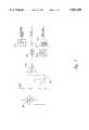
- FIG. 2is an exploded view of a wireless ultrasound transducer assembly
- FIG. 3is an exploded view of a wireless tocodynamometer transducer assembly
- FIG. 4is a diagram illustrating a mattress pad in accordance with the present invention.
- FIG. 5is a block diagram illustrating circuitry incorporated into the ultrasound transducer of FIG. 2;
- FIG. 6is a block diagram illustrating power supply and oscillator circuitry found in the ultrasound transducer of FIG. 2 as well as the TOCO transducer of FIG. 3;
- FIG. 7is a block diagram of TOCO transducer circuitry found in the transducer of FIG. 3;
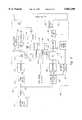
- FIG. 8is a block diagram illustrating a receiver for signals output from the ultrasound transducer of FIG. 2 and the TOCO transducer of FIG. 3.
- FIG. 1illustrates an example implementation of the invention, in which wireless fetal heart rate and maternal uterine monitoring is provided.
- a patient 10is monitored while lying on bed 12.
- a mattress pad 14is placed under the patient.
- An ultrasound transducer 16is provided for monitoring fetal heart rate.
- a tocodynamometer transducer (“TOCO” or "TOCO transducer”) 18is provided for monitoring maternal uterine activity.
- Each of transducer assemblies 16 and 18includes a transducer for providing an output signal indicative of the physiological function being monitored.
- an ultrasound transducerprovides an output signal indicative of fetal heart rate.
- the TOCO transducer assembly 18includes a strain gauge or the like for providing an output signal indicative of uterine activity.
- Both of the transducer assembliesinclude modulators for modulating a low frequency carrier by the respective output signal produced by the transducer within the transducer assembly.
- a "low frequency carrier”is defined as a carrier below the RF spectrum that can be coupled by electromagnetic induction.
- the ultrasonic transducer incorporated in transducer assembly 16can provide the transducer output signal on a carrier having a frequency of 8000 hertz, and the TOCO transducer can provide its output signal modulated on a 3100 hertz carrier.
- FM modulationis used.
- other well known types of modulationsuch as amplitude modulation (AM) could alternatively be used.
- Each of the transducer assemblies 16, 18includes a transducer coil associated with the respective modulator for coupling the modulated low frequency carrier to a corresponding receiver coil by electromagnetic induction.
- the receiver coilis located in mattress pad 14.
- the transducer assemblies 16, 18are self-contained, battery operated units that do not require any external connections.
- Each of the transducers 16, 18radiates the received fetal/maternal signals via the low power frequency modulated magnetic field.
- the magnetic fieldis sensed by the mattress pad 14, which is connected via cable 26 and connector 28 to a receiver located in a bedside fetal monitoring console 20.
- the receiver within console 20demodulates the magnetic field signals to provide ultrasound audio and uterine activity to a fetal monitor for conventional processing.
- Console 20includes a control panel 24 having standard controls such as a digital display, audio volume controls, recorder controls, and the like.
- a strip chart recorderoutputs strip documentation of patient data and monitored physiological functions on strip 22.
- Receptacles 25 and 27are provided for charging batteries located in the transducer assemblies 16 and 18.
- FIG. 2illustrates the ultrasound transducer assembly 16 in greater detail.
- a transducer knob 30threadedly engages a threaded shaft 41 extending from bracket 42 in order to hold the unit into a closed, watertight assembly.
- Knob 30can engage an opening in a strap (not shown) that straps the transducer assembly onto the patient.
- a washer 32is provided between the knob 30 and top cover 34.
- a plurality of light emitting diodes (LEDs) 35are provided in top cover 34 for indicating the condition of rechargeable (e.g., NiCad) batteries 46 within the assembly.
- Wires 36couple the LEDs 35 to a power supply printed circuit board 48 ("battery board").
- An “O" ring 38seals top cover 34 against base assembly 64, so that the unit is watertight when assembled.
- Bracket 42is held to the base 64 via screws 40, threaded connectors 44 and threaded connectors 58.
- the threaded connectors 44screw into threaded connectors 58, which in turn are screwed into threaded receptacles 59 of base 64.
- Insulating washers 53 and 62are provided as shown.
- Coil 50is a battery charging coil, which receives charging current inductively from either charging receptacle 25 or 27 of console 20 when the transducer assembly is inserted into the receptacle.
- This coilcan be constructed, for example, from 36 turns of 30 gauge solid copper wire, with a coil diameter of about 2.5 inches.
- the coilhas a center tap which is grounded.
- Coil 52is the transducer coil which couples the transducer output signal to the receiver coil (e.g., in mattress pad 14) via electromagnetic induction.
- This coilcan comprise 100-125 turns of 32 gauge solid copper wire, with a coil diameter of about 2.5 inches.
- a laminate Mylar/copper shield 56is provided between the battery board 48 and an ultrasound transducer board 60, which contains circuitry for processing and modulating the ultrasound signals which are indicative of fetal heart rate.
- transducer board 60is a printed circuit board containing various electronic components which are not specifically shown in the drawing.
- ultrasonic transducer crystals 70are mounted to the bottom of base 64. These crystals are coupled to the ultrasound transducer board 60 via wires 66.
- FIG. 3illustrates the TOCO transducer assembly 18 in greater detail. Parts which are identical with those of the ultrasound transducer bear the same reference numbers as in FIG. 2.
- the TOCO transducerdiffers from the ultrasound transducer in that instead of providing ultrasound printed circuit board 60, a TOCO transducer board 82 is provided.
- This PC boardcontains the circuitry required to process signals from a strain gauge 84 contained in the TOCO transducer base 80.
- the strain gaugeis mounted to the TOCO transducer board 82 via fasteners 86, which can comprise small nuts and bolts. Wired TOCO transducers are well known in the art, and the assembly of the strain gauge within base 80 is conventional.
- the mattress pad 14is illustrated in greater detail in FIG. 4.
- the mattress padcomprises two vinyl or other electrically nonconductive sheets 92, 94 which are fastened together using ultrasonic welding, a vinyl adhesive, or other well known technique.
- a channel 96is provided within the mattress pad by providing a depression in the interior face of one or both of sheets 92 and 94.
- the depressioncan be formed by abrasion after the sheet is manufactured or by heat and pressure during the manufacture of the sheet.
- Other techniques for forming a channel within the two adjoining sheetswill be apparent to those skilled in the art.
- a receiver coil 98is placed within channel 96 of the mattress pad 14. Although the receiver coil is illustrated in FIG. 4 using a solid line, it should be understood that the coil is sandwiched between the two sheets 92, 94 within the channel 96 provided therein.
- the coilcan be formed, for example, from ten windings of 26 gauge solid copper wire, which is periodically taped around the perimeter thereof. The coil is loosely positioned within the channel 96 so that it will not break when the mattress pad is folded.
- Cable 26which is preferably a coaxial cable, is attached to the ends of the coil 98.
- the outer shield of coax cable 26is electrically connected to one end of the coil 98 and the inner conductor is electrically connected to the other end of coil 98.
- Cable 26is terminated at the other end with a connector 28, which can comprise, for example, a standard coaxial cable connector.
- Connector 28is adapted to be connected to a corresponding socket on monitor console 20 as illustrated in FIG. 1.
- a filtering capacitor(e.g., on the order of one microfarad) can be placed across the conductors of cable 26 at the connector 28 in order to filter out high frequency interference from fluorescent lights and other electrical devices.
- FIG. 5is a block diagram of the ultrasound printed circuit board 60 illustrated in FIG. 2.
- the ultrasound transducer assemblycontains a pulse Doppler transmitter and receiver. Such components are well known in the art.
- a crystal oscillator 100(operating, e.g, at 6.144 MHz) feeds a HEX "D" flop counter 110, which divides the oscillator output by three to provide a 2.048 MHz output.
- a seven-stage binary counter 112divides by two, to provide a 1.024 MHz output for driving the ultrasonic transducer crystals 70, through a transmit gate 114.
- Counter 112also supplies a 64 kHz output to a -4 volt supply 116 that is used to power various components on the ultrasound board.
- a 32 kHz outputis provided from counter 112 to a one of ten decoder 118, which together with flip flops 120 and 122 and transmit disable switch 126 provide a desired pulse width for successive ultrasonic pulses and the waiting period therebetween.
- the 1.024 MHz outputis directed from the transducer crystals to the fetal heart, and returns with a Doppler shift, such that the fetal heart sounds are detected over a range of about 50-300 hertz.
- An RF amplifier transistor 124is used to amplify the output from the transducer crystals, in a conventional manner.
- a demodulator driver 130which receives the 1.024 MHz signal, together with a synchronous shunt switch 128 are used to subtract out the 1.024 MHz input frequency from the Doppler shifted signal to provide the fetal heartbeat output in the 50-300 hertz range.
- a sample switch 132avoids the need for complicated filtering, by taking short samples of the heart rate sounds at a high rate.
- the samples output from switch 132are input to an automatic gain control (AGC) loop containing an AGC stage 134, low pass filter 136, audio switch and low pass filter 140 and gain element 138.
- AGC loopnormalizes the amplitude of the audio before it is passed to the voltage controlled oscillator (VCO) that drives the transducer coil 52 (FIGS. 2 and 6). In this manner, the VCO can transmit a strong signal without overdriving the output.
- VCOvoltage controlled oscillator
- a high gain audio amplifier 142is provided for use with a keep-alive circuit described below in connection with FIG. 6.
- the audio output from low pass filter 136 of the ultrasound boardis input to a VCO 182.
- the audio signalis used to frequency modulate a subcarrier produced by VCO 182, and the subcarrier is applied to the transmitter coil 52 via coil driver 184.
- the transmitter coilis mounted inside the perimeter of the ultrasound transducer housing.
- the coil driver 184can simply comprise a transistor which outputs an FM modulated sine wave.
- Variable resistor 186is provided in order to adjust the frequency of VCO 182.
- the nominal output frequency of VCO 182is, e.g., 8000 Hz and for the TOCO transducer, 3100 Hz. Other frequencies can, of course, be used as long as they are chosen such that they do not substantially interfere with each other.
- transmitter and receiver coilsbasically comprise a transformer
- a nullwill occur when the transducer coil is oriented perpendicularly with respect to the receiver coil in the mattress pad.
- the range sensitivityis adjusted to reduce the null angle to a minimum.
- the operating rangeextends a few feet outside of the pad.
- transmitter coil 52it is possible for transmitter coil 52 to comprise a plurality of coils in different planes, e.g., perpendicular to each other. Instead of providing a plurality of transmitter coils in different planes, or in addition to such a structure, a plurality of receiver coils can be provided in different planes.
- the battery board of FIG. 6includes a battery charging circuit, a battery gauge, a motion sensor circuit for turning on power to the transducer assembly, and a keep-alive circuit for maintaining power when signals are being received. Essentially the same battery board is used with the ultrasound transducer and the TOCO transducer.
- a motion sensor 174which can comprise any type of switch that is activated by motion, provides an input to a motion sensor buffer 172. Examples of such switches include mercury switches and spring loaded mechanical switches that close a contact in response to any small motion.
- an output signal generated by motion sensor buffer 172is applied to an OR gate 176, the output of which activates a DC power enable circuit 178.
- switching regulator 170outputs power from battery pack 160.
- a keep-alive circuit 180senses the fetal heartbeat (ultrasound transducer) or uterine activity (TOCO transducer) and keeps the power on.
- the output of the keep-alive circuitis input to OR gate 176 to actuate DC power enable 178, which in turn actuates switching regulator 170 to output the battery power.
- the powerremains on for a number of minutes after the transducer is removed from the patient, by virtue of a timer in DC power enable circuit 178.
- Each transduceris powered by an internal rechargeable battery pack 160. Recharging is accomplished by placing the entire transducer into a receptacle 25 or 27 provided on the fetal monitor console (FIG. 1).
- the charging stationcontains a coil for inductively charging the battery pack via battery charger coil 50.
- the current received from the charging stationis passed through a full wave bridge rectifier 152 and filtered by capacitor 154.
- a pass element 156which can comprise a simple transistor, passes the charging current on to the rechargeable battery pack 160.
- a fast charge battery controller 158which is an off-the-shelf integrated circuit, terminates the charge current by either detecting full battery capacity or detecting that a maximum allowable charge time has elapsed. Once the battery is fully charged, a trickle charge is maintained to keep the battery at full capacity.
- Battery currentis sensed via a voltage divider 162 for input to a battery monitoring circuit ("battery gauge") 164.
- battery monitoring circuitThis integrated circuit keeps track of battery usage and charge currents. Compensation is made for diminished battery capacity due to age and self-discharge. Each time a complete charge/discharge cycle is performed, the programmed full capacity is updated.
- Three LED indicators 35show the approximate remaining battery charge.
- the LED indicatorsare illuminated for a brief time period after each detected motion, at the end of battery life, and when the transducer is placed into the charging station. When the battery is near the end of its useful charge, at least one of the LED indicators will flash and a signal is transmitted to the fetal monitor console to notify the operator.
- a power disable circuit 168responsive to the battery gauge actuates the DC power enable circuit 178 to turn off the switching regulator 170, thereby terminating the supply of power to the rest of the transducer circuitry.
- the switching regulatoroutputs a "low battery" signal which, in the case of the ultrasound transducer, can be used to slightly shift the VCO frequency via the variable frequency adjusting resistance 186.
- the receiver in the fetal monitor consoleUpon detecting a shifted ultrasound carrier, the receiver in the fetal monitor console will actuate a suitable low battery indicator.
- the low battery signal from switching regular 170is input to actuate to an oscillator 214 as illustrated in FIG. 7.
- the oscillator output(e.g., 80 Hz) is summed with the output carrier which carries the TOCO transducer signal for detection by the receiver circuitry in the fetal monitor console.
- FIG. 7illustrates the circuitry contained on the TOCO transducer printed circuit board 82 of FIG. 3.
- a strain gauge 200detects uterine activity and produces an output signal that is amplified in preamplifier 204.
- Optional offset adjusting resistors 202are provided to balance the strain gauge outputs.
- the amplified output from the strain gaugeis scaled in a divider 206, and summed with the output of oscillator 214 (when present).
- the resultant signalis output to the VCO 182 of a corresponding battery board 48 illustrated in FIGS. 3 and 6.
- the strain gauge output of the TOCO transducerwill FM modulate the VCO on the battery board of the TOCO transducer assembly, for output to a coil driver 184 and transmit coil 52.
- preamplifier 204(FIG. 7) is also passed through a high pass filter 208 and a high gain amplifier 212 to provide a keep-alive signal that is input to the corresponding keep-alive circuit 180 on the TOCO transducer battery board. In this manner, once power to the TOCO transducer assembly is provided, it will remain as long as uterine activity is detected by the strain gauge, and for some predetermined time thereafter.
- FIG. 8illustrates the receiver circuitry for processing the ultrasound and TOCO signals in the fetal monitor console.
- the signals coupled to the mattress padare input to a preamplifier 252 via the mattress pad input 250.
- the TOCO and ultrasound carrier frequencieswill be chosen to be noninterfering with each other or with other signals such as the pulse Doppler repetition frequency. It has been found that an ultrasound carrier frequency of 8000 hertz and TOCO transducer carrier frequency of 3100 hertz is satisfactory.
- preamplifier 252is input to a TOCO transducer processing circuit generally designated 253 and to ultrasound transducer processing circuitry generally designated 255.
- the signalis received by a low pass filter 254 which passes the 3100 hertz TOCO carrier to a comparator 256.
- the comparatorcompares the TOCO carrier to a DC level and outputs a square wave to a phase-lock-loop (PLL) circuit 258 which locks onto the input frequency.
- PLLphase-lock-loop
- the output of the PLLis a representation of TOCO pressure.
- This signalis low pass filtered by filter 262 and converted to a digital signal by comparators 264 and 268 which also receive an input from ramp generator 266. As indicated in FIG.
- comparator 264compares the TOCO signal to the ramp generator output.
- Comparator 268compares the ramp generator output to a reference voltage.
- the combined output of the comparatorsis a pulse width modulated signal representative of uterine activity, which is input to a conventional microprocessor controlled signal analyzer 275 in the fetal monitor console.
- a comparator 270is provided in the TOCO section of the receiver for detecting the presence of a wireless TOCO signal. If no wireless signal is present (i.e., no modulated low frequency TOCO carrier is detected), a transistor 272 will output a signal to signal analyzer 275 in order to switch the fetal monitor to a cable mode of operation. In the cable mode, the fetal monitor uses conventional wired transducer assemblies.
- the ultrasound section of the receiverincludes a high pass filter 280 that recovers the ultrasound transducer carrier from the signal output by preamplifier 252. After processing by a comparator 282 and phase-lock-loop 286, the signal is demodulated using a monostable multivibrator (one-shot) 292 and low pass filter 296. The demodulated audio is then provided to the conventional signal analyzer 275.
- Amplifier 284detects the level of the ultrasound carrier. If the level is too weak, amplifier 284 actuates an audio disable switch 284 to mute the audio via low pass filter 296.
- a comparator 288 and transistor 290analogous to comparator 270 and transistor 272 of the TOCO receiver circuitry, switch the fetal monitor to the cable mode of operation when no wireless ultrasound signal is present.
- Both the TOCO section 253 and ultrasound section 255are provided with respective low battery detection circuits 260, 298.
- the TOCO section low battery detection circuit 260detects the 80 hertz signal added to the TOCO transducer output via oscillator 214, discussed above in connection with FIG. 7.
- the ultrasound low battery detector 298detects a frequency shift introduced via the VCO 182 in the ultrasound transducer assembly when the battery power is low, as discussed above in connection with FIG. 6. The detection of a low battery signal in either the TOCO transducer or the ultrasound transducer will result in a notification signal being generated in signal analyzer 275.
- the present inventionprovides a wireless patient monitoring apparatus in which low frequency inductive coupling is used to communicate signals from self-contained, portable transducer assemblies to patient monitoring apparatus.
- the signalsare coupled from a transmitter coil in the transducer assembly to a receiver coil, which can be provided, for example, in a mattress pad.
- the use of low frequency inductive couplingavoids the drawbacks of prior art radio frequency telemetry systems, such as interference with other instrumentation.
Landscapes
- Health & Medical Sciences (AREA)
- Life Sciences & Earth Sciences (AREA)
- Engineering & Computer Science (AREA)
- Veterinary Medicine (AREA)
- Biomedical Technology (AREA)
- Biophysics (AREA)
- General Health & Medical Sciences (AREA)
- Pathology (AREA)
- Animal Behavior & Ethology (AREA)
- Physics & Mathematics (AREA)
- Public Health (AREA)
- Heart & Thoracic Surgery (AREA)
- Medical Informatics (AREA)
- Molecular Biology (AREA)
- Surgery (AREA)
- Radiology & Medical Imaging (AREA)
- Nuclear Medicine, Radiotherapy & Molecular Imaging (AREA)
- Pregnancy & Childbirth (AREA)
- Gynecology & Obstetrics (AREA)
- Computer Networks & Wireless Communication (AREA)
- Cardiology (AREA)
- Reproductive Health (AREA)
- Measurement And Recording Of Electrical Phenomena And Electrical Characteristics Of The Living Body (AREA)
- Ultra Sonic Daignosis Equipment (AREA)
- Measuring Pulse, Heart Rate, Blood Pressure Or Blood Flow (AREA)
Abstract
Description
Claims (27)
Priority Applications (1)
| Application Number | Priority Date | Filing Date | Title |
|---|---|---|---|
| US08/745,020US5882300A (en) | 1996-11-07 | 1996-11-07 | Wireless patient monitoring apparatus using inductive coupling |
Applications Claiming Priority (1)
| Application Number | Priority Date | Filing Date | Title |
|---|---|---|---|
| US08/745,020US5882300A (en) | 1996-11-07 | 1996-11-07 | Wireless patient monitoring apparatus using inductive coupling |
Publications (1)
| Publication Number | Publication Date |
|---|---|
| US5882300Atrue US5882300A (en) | 1999-03-16 |
Family
ID=24994900
Family Applications (1)
| Application Number | Title | Priority Date | Filing Date |
|---|---|---|---|
| US08/745,020Expired - LifetimeUS5882300A (en) | 1996-11-07 | 1996-11-07 | Wireless patient monitoring apparatus using inductive coupling |
Country Status (1)
| Country | Link |
|---|---|
| US (1) | US5882300A (en) |
Cited By (110)
| Publication number | Priority date | Publication date | Assignee | Title |
|---|---|---|---|---|
| US6102863A (en)* | 1998-11-20 | 2000-08-15 | Atl Ultrasound | Ultrasonic diagnostic imaging system with thin cable ultrasonic probes |
| US6113547A (en)* | 1998-11-20 | 2000-09-05 | Atl Ultrasound, Inc. | Ultrasonic diagnostic imaging with cordless scanhead transmission system |
| US6117085A (en)* | 1998-11-20 | 2000-09-12 | Atl Ultrasound, Inc. | Ultrasonic diagnostic imaging system with cordless scanhead charger |
| US6142946A (en)* | 1998-11-20 | 2000-11-07 | Atl Ultrasound, Inc. | Ultrasonic diagnostic imaging system with cordless scanheads |
| WO2001074447A3 (en)* | 2000-03-31 | 2002-01-31 | Cardiac Pacemakers Inc | Inductive coil apparatus for bio-medical telemetry |
| US20020084698A1 (en)* | 2000-11-20 | 2002-07-04 | Kelly Clifford Mark | Electrically isolated power and signal coupler system for a patient connected device |
| US20020103417A1 (en)* | 1999-03-01 | 2002-08-01 | Gazdzinski Robert F. | Endoscopic smart probe and method |
| US20020109621A1 (en)* | 2000-04-18 | 2002-08-15 | Motorola, Inc. | Wireless system protocol for telemetry monitoring |
| US6468234B1 (en) | 2000-07-14 | 2002-10-22 | The Board Of Trustees Of The Leland Stanford Junior University | SleepSmart |
| US20030040305A1 (en)* | 2000-04-18 | 2003-02-27 | Motorola, Inc. | Programmable wireless electrode system for medical monitoring |
| US6561978B1 (en) | 1999-02-12 | 2003-05-13 | Cygnus, Inc. | Devices and methods for frequent measurement of an analyte present in a biological system |
| US20030122677A1 (en)* | 1997-03-07 | 2003-07-03 | Cardionet, Inc. | Reprogrammable remote sensor monitoring system |
| US20030153831A1 (en)* | 2002-01-22 | 2003-08-14 | Jona Zumeris | System and method for detection of motion |
| US20030153832A1 (en)* | 2002-01-22 | 2003-08-14 | Jona Zumeris | System and method for smart monitoring within a body |
| US6607486B1 (en)* | 2000-01-10 | 2003-08-19 | Richard L. Watson | Beltless fiber optic labor contraction sensing device |
| US20030172940A1 (en)* | 2002-03-13 | 2003-09-18 | Cardionet, Inc. | Method and apparatus for monitoring and communicating with an implanted medical device |
| US20030199777A1 (en)* | 2000-07-18 | 2003-10-23 | Motorola, Inc. | Wireless electrocardiograph system and method |
| US6664893B1 (en) | 2001-04-23 | 2003-12-16 | Cardionet, Inc. | Method for controlling access to medical monitoring device service |
| US6665385B2 (en) | 2001-04-23 | 2003-12-16 | Cardionet, Inc. | Medical monitoring system having multipath communications capability |
| US6681427B2 (en) | 2001-06-19 | 2004-01-27 | Anderson Bio-Bed, Incorporated | Apparatus for imparting continuous motion to a mattress |
| US6694177B2 (en) | 2001-04-23 | 2004-02-17 | Cardionet, Inc. | Control of data transmission between a remote monitoring unit and a central unit |
| US20040073127A1 (en)* | 2001-07-17 | 2004-04-15 | Gmp Companies, Inc. | Wireless ECG system |
| US6749566B2 (en) | 2001-02-14 | 2004-06-15 | Draeger Medical Systems, Inc. | Patient monitoring area network |
| US20040133115A1 (en)* | 2002-11-01 | 2004-07-08 | Hamilton Emily F. | Method and apparatus for identifying heart rate feature events |
| US20040133117A1 (en)* | 1999-10-28 | 2004-07-08 | Morten Eriksen | Volumetric physiological measuring system and method |
| US20040149533A1 (en)* | 2003-01-24 | 2004-08-05 | Joanne Milano | Cable management and contact monitoring system |
| US20040186357A1 (en)* | 2002-08-20 | 2004-09-23 | Welch Allyn, Inc. | Diagnostic instrument workstation |
| US6801137B2 (en) | 2001-04-23 | 2004-10-05 | Cardionet, Inc. | Bidirectional communication between a sensor unit and a monitor unit in patient monitoring |
| US20040249279A1 (en)* | 2003-01-30 | 2004-12-09 | Michael Maschke | Patient monitor for processing signals from an ultrasound probe |
| US20040259270A1 (en)* | 2003-06-19 | 2004-12-23 | Wolf David E. | System, device and method for exciting a sensor and detecting analyte |
| US20050075583A1 (en)* | 2001-05-21 | 2005-04-07 | Sullivan Colin Edward | Electronic monitoring system |
| US20050119580A1 (en)* | 2001-04-23 | 2005-06-02 | Eveland Doug C. | Controlling access to a medical monitoring system |
| US20050177052A1 (en)* | 2001-07-17 | 2005-08-11 | Gmp Wireless Medicine, Inc. | Wireless ECG system |
| US6945941B2 (en) | 1998-10-30 | 2005-09-20 | Volusense As | Volumetric physiological measuring system and method |
| US20050265267A1 (en)* | 2004-05-17 | 2005-12-01 | Sonosite, Inc. | Processing of medical signals |
| US20050267339A1 (en)* | 2004-05-26 | 2005-12-01 | Udo Beckmann | Patient care unit with a bed |
| US20050288571A1 (en)* | 2002-08-20 | 2005-12-29 | Welch Allyn, Inc. | Mobile medical workstation |
| US7183930B2 (en) | 2003-07-18 | 2007-02-27 | Intelligent Mechatronic Systems Inc. | Occupant heartbeat detection and monitoring system |
| US7215991B2 (en) | 1993-09-04 | 2007-05-08 | Motorola, Inc. | Wireless medical diagnosis and monitoring equipment |
| US20070112274A1 (en)* | 2005-11-14 | 2007-05-17 | Edwards Lifesciences Corporation | Wireless communication system for pressure monitoring |
| US20070109117A1 (en)* | 2005-11-14 | 2007-05-17 | Edwards Lifesciences Corporation | Wireless communication protocol for a medical sensor system |
| US20080115792A1 (en)* | 2004-01-13 | 2008-05-22 | Michael Albertus Burger | Device for Preventing Bruxism |
| US20080139953A1 (en)* | 2006-11-01 | 2008-06-12 | Welch Allyn, Inc. | Body worn physiological sensor device having a disposable electrode module |
| US20080221474A1 (en)* | 2005-05-31 | 2008-09-11 | Koninklijke Philips Electronics N. V. | Method and Apparatus for Inductively Measuring the Bio-Impedance of a User's Body |
| US20080262351A1 (en)* | 2004-09-30 | 2008-10-23 | Koninklijke Philips Electronics, N.V. | Microbeamforming Transducer Architecture |
| US20080281168A1 (en)* | 2005-01-13 | 2008-11-13 | Welch Allyn, Inc. | Vital Signs Monitor |
| US20090036780A1 (en)* | 2007-08-03 | 2009-02-05 | Innoscion, Llc | Wired and Wireless Remotely Controlled Ultrasonic Transducer and Imaging Apparatus |
| US7510527B1 (en)* | 2004-12-02 | 2009-03-31 | Juan Enrique Cienfuegos | Method of using an illuminated display system |
| US7549961B1 (en) | 2003-07-31 | 2009-06-23 | Sonosite, Inc. | System and method supporting imaging and monitoring applications |
| US20100010320A1 (en)* | 2008-07-07 | 2010-01-14 | Perkins David G | Mobile medical workstation and a temporarily associating mobile computing device |
| US20100041975A1 (en)* | 2008-07-16 | 2010-02-18 | MASSACHUSETTS GENERAL HOSPITAL D/B/A Massachusetts General Hospital | Patient monitoring systems and methods |
| US20100152562A1 (en)* | 2005-02-08 | 2010-06-17 | Abbott Diabetes Care Inc. | RF Tag on Test Strips, Test Strip Vials and Boxes |
| US20100268120A1 (en)* | 2009-04-20 | 2010-10-21 | Morten Eriksen | Coil System and Method for Obtaining Volumetric Physiological Measurements |
| US20100298687A1 (en)* | 2009-05-22 | 2010-11-25 | Hoi-Jun Yoo | Wearable monitoring apparatus and driving method thereof |
| US7914442B1 (en) | 1999-03-01 | 2011-03-29 | Gazdzinski Robert F | Endoscopic smart probe and method |
| US8068897B1 (en) | 1999-03-01 | 2011-11-29 | Gazdzinski Robert F | Endoscopic smart probe and method |
| US20120179045A1 (en)* | 2011-01-07 | 2012-07-12 | General Electrical Company | Fetal Scalp Doppler Device and System |
| US20120271160A1 (en)* | 2009-06-18 | 2012-10-25 | Clive Buckberry | Vascular Access Monitoring Device |
| US20130006153A1 (en)* | 2009-12-31 | 2013-01-03 | Zetroz Llc | Low-profile ultrasound transducer |
| US8672842B2 (en) | 2010-08-24 | 2014-03-18 | Evacusled Inc. | Smart mattress |
| WO2014053958A1 (en)* | 2012-10-02 | 2014-04-10 | Koninklijke Philips N.V. | Tool for opening and closing a transducer housing |
| US20140100468A1 (en)* | 2012-10-09 | 2014-04-10 | Quanta Computer Inc. | Physiological signal detection device |
| CN104248455A (en)* | 2014-08-20 | 2014-12-31 | 深圳市理邦精密仪器股份有限公司 | Management control method and system of wireless sensors for multi-bed fetal monitor |
| US9333291B2 (en) | 2014-01-16 | 2016-05-10 | Hospira, Inc. | Infusion pump battery capacity management and battery charge alert system and method |
| CN105996996A (en)* | 2016-05-03 | 2016-10-12 | 华南理工大学 | Electromagnetic ultrasonic human body data acquisition and auxiliary health care based intelligent mattress |
| US9480455B2 (en) | 2009-06-18 | 2016-11-01 | Quanta Fluid Solutions, Ltd. | Vascular access monitoring device |
| WO2017003735A1 (en)* | 2015-06-30 | 2017-01-05 | General Electric Company | Wireless charging and pairing of wireless associated devices |
| US9700223B2 (en) | 2011-12-02 | 2017-07-11 | Lumiradx Uk Ltd | Method for forming a component of a wearable monitor |
| US9717412B2 (en) | 2010-11-05 | 2017-08-01 | Gary And Mary West Health Institute | Wireless fetal monitoring system |
| US9734304B2 (en) | 2011-12-02 | 2017-08-15 | Lumiradx Uk Ltd | Versatile sensors with data fusion functionality |
| US9820718B2 (en) | 2012-03-01 | 2017-11-21 | Syracuse University | Enhanced electronic external fetal monitoring system |
| US9861268B2 (en) | 1999-03-01 | 2018-01-09 | West View Research, Llc | Methods of processing data obtained from medical device |
| US9872087B2 (en) | 2010-10-19 | 2018-01-16 | Welch Allyn, Inc. | Platform for patient monitoring |
| US20180049701A1 (en)* | 2015-03-13 | 2018-02-22 | Emfit Oy | Mattress for resting or sleeping of a person |
| US20180153506A1 (en)* | 2016-12-06 | 2018-06-07 | Gerardo Rodriquez | Stand-alone continuous cardiac doppler pulse monitoring patch with integral visual and auditory alerts, and patch-display system and method |
| US10022498B2 (en) | 2011-12-16 | 2018-07-17 | Icu Medical, Inc. | System for monitoring and delivering medication to a patient and method of using the same to minimize the risks associated with automated therapy |
| US10046112B2 (en) | 2013-05-24 | 2018-08-14 | Icu Medical, Inc. | Multi-sensor infusion system for detecting air or an occlusion in the infusion system |
| US10166328B2 (en) | 2013-05-29 | 2019-01-01 | Icu Medical, Inc. | Infusion system which utilizes one or more sensors and additional information to make an air determination regarding the infusion system |
| US10238362B2 (en) | 2010-04-26 | 2019-03-26 | Gary And Mary West Health Institute | Integrated wearable device for detection of fetal heart rate and material uterine contractions with wireless communication capability |
| WO2019089609A1 (en)* | 2017-10-31 | 2019-05-09 | Edwards Lifesciences Corporation | Non-invasive wearable heart valve monitor |
| US10342917B2 (en) | 2014-02-28 | 2019-07-09 | Icu Medical, Inc. | Infusion system and method which utilizes dual wavelength optical air-in-line detection |
| US10430761B2 (en) | 2011-08-19 | 2019-10-01 | Icu Medical, Inc. | Systems and methods for a graphical interface including a graphical representation of medical data |
| US10463788B2 (en) | 2012-07-31 | 2019-11-05 | Icu Medical, Inc. | Patient care system for critical medications |
| US10578474B2 (en) | 2012-03-30 | 2020-03-03 | Icu Medical, Inc. | Air detection system and method for detecting air in a pump of an infusion system |
| US10596316B2 (en) | 2013-05-29 | 2020-03-24 | Icu Medical, Inc. | Infusion system and method of use which prevents over-saturation of an analog-to-digital converter |
| US10635784B2 (en) | 2007-12-18 | 2020-04-28 | Icu Medical, Inc. | User interface improvements for medical devices |
| US10656894B2 (en) | 2017-12-27 | 2020-05-19 | Icu Medical, Inc. | Synchronized display of screen content on networked devices |
| US10850024B2 (en) | 2015-03-02 | 2020-12-01 | Icu Medical, Inc. | Infusion system, device, and method having advanced infusion features |
| US10945706B2 (en) | 2017-05-05 | 2021-03-16 | Biim Ultrasound As | Hand held ultrasound probe |
| EP2114282B1 (en)* | 2007-02-08 | 2021-05-19 | Siemens Medical Solutions USA, Inc. | Probes for ultrasound imaging systems |
| US11135360B1 (en) | 2020-12-07 | 2021-10-05 | Icu Medical, Inc. | Concurrent infusion with common line auto flush |
| US11246985B2 (en) | 2016-05-13 | 2022-02-15 | Icu Medical, Inc. | Infusion pump system and method with common line auto flush |
| US11278671B2 (en) | 2019-12-04 | 2022-03-22 | Icu Medical, Inc. | Infusion pump with safety sequence keypad |
| US11324888B2 (en) | 2016-06-10 | 2022-05-10 | Icu Medical, Inc. | Acoustic flow sensor for continuous medication flow measurements and feedback control of infusion |
| US11344673B2 (en) | 2014-05-29 | 2022-05-31 | Icu Medical, Inc. | Infusion system and pump with configurable closed loop delivery rate catch-up |
| US11344668B2 (en) | 2014-12-19 | 2022-05-31 | Icu Medical, Inc. | Infusion system with concurrent TPN/insulin infusion |
| US11571499B2 (en) | 2015-12-30 | 2023-02-07 | Quanta Dialysis Technologies Ltd. | Dialysis machine |
| US11583618B2 (en) | 2014-06-02 | 2023-02-21 | Quanta Dialysis Technologies Limited | Method of heat sanitization of a haemodialysis water circuit using a calculated dose |
| US11660382B2 (en) | 2016-12-23 | 2023-05-30 | Quanta Dialysis Technologies Limited | Valve leak detection system |
| US11806115B2 (en) | 2020-05-21 | 2023-11-07 | GE Precision Healthcare LLC | Systems and methods for dynamic selection of sensors for obtaining physiological data from a patient |
| US11883361B2 (en) | 2020-07-21 | 2024-01-30 | Icu Medical, Inc. | Fluid transfer devices and methods of use |
| USRE49881E1 (en) | 2013-03-28 | 2024-03-26 | Quanta Fluid Solutions Ltd. | Re-use of a hemodialysis cartridge |
| USRE50004E1 (en) | 2013-08-14 | 2024-06-11 | Quanta Dialysis Technologies Ltd. | Dual haemodialysis and haemodiafiltration blood treatment device |
| US12011528B2 (en) | 2017-02-02 | 2024-06-18 | Quanta Dialysis Technologies Ltd. | Phased convective operation |
| US12163513B2 (en) | 2016-02-10 | 2024-12-10 | Quanta Dialysis Technologies Ltd. | Membrane pump usage condition detection |
| US12251504B2 (en) | 2017-06-30 | 2025-03-18 | Quanta Dialysis Technologies Ltd. | Dialysis systems, devices and methods |
| USD1070090S1 (en) | 2017-09-28 | 2025-04-08 | Quanta Dialysis Technologies Ltd. | Dialysis machine |
| US12350233B2 (en) | 2021-12-10 | 2025-07-08 | Icu Medical, Inc. | Medical fluid compounding systems with coordinated flow control |
| US12357738B2 (en) | 2019-05-31 | 2025-07-15 | Quanta Dialysis Technologies Limited | Source container connector |
| USD1091564S1 (en) | 2021-10-13 | 2025-09-02 | Icu Medical, Inc. | Display screen or portion thereof with graphical user interface for a medical device |
Citations (12)
| Publication number | Priority date | Publication date | Assignee | Title |
|---|---|---|---|---|
| US3638642A (en)* | 1970-03-13 | 1972-02-01 | Teledoc Corp | Patient monitoring system with bedsheet-mounted antenna |
| US3921621A (en)* | 1973-08-23 | 1975-11-25 | Lee R Baessler | Method and system utilizing a disposable transmitter for monitoring a patient{3 s condition |
| US3949388A (en)* | 1972-11-13 | 1976-04-06 | Monitron Industries, Inc. | Physiological sensor and transmitter |
| US4109644A (en)* | 1977-01-12 | 1978-08-29 | The United States Of America As Represented By The United States National Aeronautics And Space Administration | Miniature implantable ultrasonic echosonometer |
| US4186749A (en)* | 1977-05-12 | 1980-02-05 | The United States Of America As Represented By The Administrator Of The National Aeronautics And Space Administration | Induction powered biological radiosonde |
| US4198987A (en)* | 1978-01-09 | 1980-04-22 | Cain Clarence P | Measuring system including elements implantable beneath the skin |
| US4373527A (en)* | 1979-04-27 | 1983-02-15 | The Johns Hopkins University | Implantable, programmable medication infusion system |
| US4573475A (en)* | 1984-11-15 | 1986-03-04 | Hewlett-Packard Company | Receiving radiation from loops in a common plane for monitoring hospital patients leadlessly |
| US5143171A (en)* | 1990-09-24 | 1992-09-01 | Sinco Incorporated | Roof lifeline safety system and anchor assembly therefor |
| US5373852A (en)* | 1993-06-25 | 1994-12-20 | The Regents Of The University Of California | Monitoring uterine contractions by radiotelemetric transmission |
| US5511553A (en)* | 1989-02-15 | 1996-04-30 | Segalowitz; Jacob | Device-system and method for monitoring multiple physiological parameters (MMPP) continuously and simultaneously |
| US5549113A (en)* | 1992-11-09 | 1996-08-27 | I Am Fine, Inc. | Apparatus and method for remote monitoring of physiological parameters |
- 1996
- 1996-11-07USUS08/745,020patent/US5882300A/ennot_activeExpired - Lifetime
Patent Citations (13)
| Publication number | Priority date | Publication date | Assignee | Title |
|---|---|---|---|---|
| US3638642A (en)* | 1970-03-13 | 1972-02-01 | Teledoc Corp | Patient monitoring system with bedsheet-mounted antenna |
| US3949388A (en)* | 1972-11-13 | 1976-04-06 | Monitron Industries, Inc. | Physiological sensor and transmitter |
| US3921621A (en)* | 1973-08-23 | 1975-11-25 | Lee R Baessler | Method and system utilizing a disposable transmitter for monitoring a patient{3 s condition |
| US4109644A (en)* | 1977-01-12 | 1978-08-29 | The United States Of America As Represented By The United States National Aeronautics And Space Administration | Miniature implantable ultrasonic echosonometer |
| US4186749A (en)* | 1977-05-12 | 1980-02-05 | The United States Of America As Represented By The Administrator Of The National Aeronautics And Space Administration | Induction powered biological radiosonde |
| US4198987A (en)* | 1978-01-09 | 1980-04-22 | Cain Clarence P | Measuring system including elements implantable beneath the skin |
| US4373527A (en)* | 1979-04-27 | 1983-02-15 | The Johns Hopkins University | Implantable, programmable medication infusion system |
| US4373527B1 (en)* | 1979-04-27 | 1995-06-27 | Univ Johns Hopkins | Implantable programmable medication infusion system |
| US4573475A (en)* | 1984-11-15 | 1986-03-04 | Hewlett-Packard Company | Receiving radiation from loops in a common plane for monitoring hospital patients leadlessly |
| US5511553A (en)* | 1989-02-15 | 1996-04-30 | Segalowitz; Jacob | Device-system and method for monitoring multiple physiological parameters (MMPP) continuously and simultaneously |
| US5143171A (en)* | 1990-09-24 | 1992-09-01 | Sinco Incorporated | Roof lifeline safety system and anchor assembly therefor |
| US5549113A (en)* | 1992-11-09 | 1996-08-27 | I Am Fine, Inc. | Apparatus and method for remote monitoring of physiological parameters |
| US5373852A (en)* | 1993-06-25 | 1994-12-20 | The Regents Of The University Of California | Monitoring uterine contractions by radiotelemetric transmission |
Non-Patent Citations (1)
| Title |
|---|
| IM77 Intrapartum Fetal Monitor, Advanced Medical Systems Brochure, May 1995.* |
Cited By (228)
| Publication number | Priority date | Publication date | Assignee | Title |
|---|---|---|---|---|
| US7215991B2 (en) | 1993-09-04 | 2007-05-08 | Motorola, Inc. | Wireless medical diagnosis and monitoring equipment |
| US8771184B2 (en) | 1993-09-04 | 2014-07-08 | Body Science Llc | Wireless medical diagnosis and monitoring equipment |
| US20030122677A1 (en)* | 1997-03-07 | 2003-07-03 | Cardionet, Inc. | Reprogrammable remote sensor monitoring system |
| US6940403B2 (en) | 1997-03-07 | 2005-09-06 | Cardionet, Inc. | Reprogrammable remote sensor monitoring system |
| US20080270067A1 (en)* | 1998-10-30 | 2008-10-30 | Volusense As | Volumetric physiological measuring system and method |
| US6945941B2 (en) | 1998-10-30 | 2005-09-20 | Volusense As | Volumetric physiological measuring system and method |
| US8500651B2 (en) | 1998-10-30 | 2013-08-06 | Volusense As | Volumetric physiological measuring system and method |
| US6142946A (en)* | 1998-11-20 | 2000-11-07 | Atl Ultrasound, Inc. | Ultrasonic diagnostic imaging system with cordless scanheads |
| US6113547A (en)* | 1998-11-20 | 2000-09-05 | Atl Ultrasound, Inc. | Ultrasonic diagnostic imaging with cordless scanhead transmission system |
| US6117085A (en)* | 1998-11-20 | 2000-09-12 | Atl Ultrasound, Inc. | Ultrasonic diagnostic imaging system with cordless scanhead charger |
| US6102863A (en)* | 1998-11-20 | 2000-08-15 | Atl Ultrasound | Ultrasonic diagnostic imaging system with thin cable ultrasonic probes |
| US7163511B2 (en)* | 1999-02-12 | 2007-01-16 | Animas Technologies, Llc | Devices and methods for frequent measurement of an analyte present in a biological system |
| US6561978B1 (en) | 1999-02-12 | 2003-05-13 | Cygnus, Inc. | Devices and methods for frequent measurement of an analyte present in a biological system |
| US20030144581A1 (en)* | 1999-02-12 | 2003-07-31 | Cygnus, Inc. | Devices and methods for frequent measurement of an analyte present in a biological system |
| US8068897B1 (en) | 1999-03-01 | 2011-11-29 | Gazdzinski Robert F | Endoscopic smart probe and method |
| US6984205B2 (en)* | 1999-03-01 | 2006-01-10 | Gazdzinski Robert F | Endoscopic smart probe and method |
| US10098568B2 (en) | 1999-03-01 | 2018-10-16 | West View Research, Llc | Computerized apparatus with ingestible probe |
| US10028645B2 (en) | 1999-03-01 | 2018-07-24 | West View Research, Llc | Computerized information collection and processing apparatus |
| US8317681B1 (en) | 1999-03-01 | 2012-11-27 | Gazdzinski Robert F | Endoscopic smart probe and method |
| US10154777B2 (en) | 1999-03-01 | 2018-12-18 | West View Research, Llc | Computerized information collection and processing apparatus and methods |
| US9913575B2 (en) | 1999-03-01 | 2018-03-13 | West View Research, Llc | Methods of processing data obtained from medical device |
| US9861296B2 (en) | 1999-03-01 | 2018-01-09 | West View Research, Llc | Ingestible probe with agent delivery |
| US9861268B2 (en) | 1999-03-01 | 2018-01-09 | West View Research, Llc | Methods of processing data obtained from medical device |
| US10973397B2 (en) | 1999-03-01 | 2021-04-13 | West View Research, Llc | Computerized information collection and processing apparatus |
| US10028646B2 (en) | 1999-03-01 | 2018-07-24 | West View Research, Llc | Computerized information collection and processing apparatus |
| US8636649B1 (en) | 1999-03-01 | 2014-01-28 | West View Research, Llc | Endoscopic smart probe and method |
| US7914442B1 (en) | 1999-03-01 | 2011-03-29 | Gazdzinski Robert F | Endoscopic smart probe and method |
| US20020103417A1 (en)* | 1999-03-01 | 2002-08-01 | Gazdzinski Robert F. | Endoscopic smart probe and method |
| US7390307B2 (en) | 1999-10-28 | 2008-06-24 | Volusense As | Volumetric physiological measuring system and method |
| US20040133117A1 (en)* | 1999-10-28 | 2004-07-08 | Morten Eriksen | Volumetric physiological measuring system and method |
| US6607486B1 (en)* | 2000-01-10 | 2003-08-19 | Richard L. Watson | Beltless fiber optic labor contraction sensing device |
| US7025723B1 (en) | 2000-01-10 | 2006-04-11 | Watson Richard L | Beltless fiber optic labor contraction sensing device |
| US6895281B1 (en) | 2000-03-31 | 2005-05-17 | Cardiac Pacemakers, Inc. | Inductive coil apparatus for bio-medical telemetry |
| WO2001074447A3 (en)* | 2000-03-31 | 2002-01-31 | Cardiac Pacemakers Inc | Inductive coil apparatus for bio-medical telemetry |
| US20030040305A1 (en)* | 2000-04-18 | 2003-02-27 | Motorola, Inc. | Programmable wireless electrode system for medical monitoring |
| US6987965B2 (en) | 2000-04-18 | 2006-01-17 | Motorola, Inc. | Programmable wireless electrode system for medical monitoring |
| US20020109621A1 (en)* | 2000-04-18 | 2002-08-15 | Motorola, Inc. | Wireless system protocol for telemetry monitoring |
| US6897788B2 (en) | 2000-04-18 | 2005-05-24 | Motorola, Inc. | Wireless system protocol for telemetry monitoring |
| US7171166B2 (en) | 2000-04-18 | 2007-01-30 | Motorola Inc. | Programmable wireless electrode system for medical monitoring |
| US6468234B1 (en) | 2000-07-14 | 2002-10-22 | The Board Of Trustees Of The Leland Stanford Junior University | SleepSmart |
| US20030199777A1 (en)* | 2000-07-18 | 2003-10-23 | Motorola, Inc. | Wireless electrocardiograph system and method |
| US7272428B2 (en) | 2000-07-18 | 2007-09-18 | Motorola, Inc. | Wireless electrocardiograph system and method |
| US6819013B2 (en)* | 2000-11-20 | 2004-11-16 | Draeger Medical Systems, Inc. | Electrically isolated power and signal coupler system for a patient connected device |
| US20020084698A1 (en)* | 2000-11-20 | 2002-07-04 | Kelly Clifford Mark | Electrically isolated power and signal coupler system for a patient connected device |
| US6749566B2 (en) | 2001-02-14 | 2004-06-15 | Draeger Medical Systems, Inc. | Patient monitoring area network |
| US8425414B2 (en) | 2001-04-23 | 2013-04-23 | Braemar Manufacturing, Llc | Controlling access to a medical monitoring system |
| US20070288067A1 (en)* | 2001-04-23 | 2007-12-13 | Cardionet, Inc. | Controlling Access to a Medical Monitoring System |
| US6694177B2 (en) | 2001-04-23 | 2004-02-17 | Cardionet, Inc. | Control of data transmission between a remote monitoring unit and a central unit |
| US8290129B2 (en) | 2001-04-23 | 2012-10-16 | Cardionet, Inc. | Medical monitoring system having multiple communications channels |
| USRE43767E1 (en) | 2001-04-23 | 2012-10-23 | Cardionet, Inc. | Control of data transmission between a remote monitoring unit and a central unit |
| US6801137B2 (en) | 2001-04-23 | 2004-10-05 | Cardionet, Inc. | Bidirectional communication between a sensor unit and a monitor unit in patient monitoring |
| US20040260189A1 (en)* | 2001-04-23 | 2004-12-23 | Cardionet, Inc., A California Corporation. | Control of data transmission between a remote monitoring unit and a central unit |
| US20040085186A1 (en)* | 2001-04-23 | 2004-05-06 | Cardionet, Inc., A California Corporation | Controlling access to a medical monitoring system |
| US7002468B2 (en) | 2001-04-23 | 2006-02-21 | Cardionet, Inc. | Controlling access to a medical monitoring system |
| US20050119580A1 (en)* | 2001-04-23 | 2005-06-02 | Eveland Doug C. | Controlling access to a medical monitoring system |
| US20070130657A1 (en)* | 2001-04-23 | 2007-06-07 | Cardionet, Inc., A California Corporation | Medical monitoring system having multiple communications channels |
| US7130396B2 (en) | 2001-04-23 | 2006-10-31 | Cardionet, Inc. | Medical monitoring system having multiple communications channels |
| US6664893B1 (en) | 2001-04-23 | 2003-12-16 | Cardionet, Inc. | Method for controlling access to medical monitoring device service |
| US6665385B2 (en) | 2001-04-23 | 2003-12-16 | Cardionet, Inc. | Medical monitoring system having multipath communications capability |
| US9474445B2 (en) | 2001-04-23 | 2016-10-25 | Braemar Manufacturing, Llc | Controlling access to medical monitoring system |
| US20050075583A1 (en)* | 2001-05-21 | 2005-04-07 | Sullivan Colin Edward | Electronic monitoring system |
| US6681427B2 (en) | 2001-06-19 | 2004-01-27 | Anderson Bio-Bed, Incorporated | Apparatus for imparting continuous motion to a mattress |
| US20040073127A1 (en)* | 2001-07-17 | 2004-04-15 | Gmp Companies, Inc. | Wireless ECG system |
| US20050177052A1 (en)* | 2001-07-17 | 2005-08-11 | Gmp Wireless Medicine, Inc. | Wireless ECG system |
| US20110160604A1 (en)* | 2001-07-17 | 2011-06-30 | Rud Istvan | Wireless ecg system |
| US20050251004A1 (en)* | 2001-07-17 | 2005-11-10 | Gmp/Wireless Medicine, Inc. | Radiolucent chest assembly |
| US7860557B2 (en) | 2001-07-17 | 2010-12-28 | Lifesync Corporation | Radiolucent chest assembly |
| US7933642B2 (en) | 2001-07-17 | 2011-04-26 | Rud Istvan | Wireless ECG system |
| US8255041B2 (en) | 2001-07-17 | 2012-08-28 | Lifesync Corporation | Wireless ECG system |
| US20050251003A1 (en)* | 2001-07-17 | 2005-11-10 | Gmp/Wireless Medicine, Inc. | Disposable chest assembly |
| US7403808B2 (en) | 2001-07-17 | 2008-07-22 | Lifesync Corporation | Wireless ECG system |
| US20050251002A1 (en)* | 2001-07-17 | 2005-11-10 | Gmp/Wireless Medicine, Inc. | Vital signs monitoring assembly having elastomeric connectors |
| US7197357B2 (en) | 2001-07-17 | 2007-03-27 | Life Sync Corporation | Wireless ECG system |
| US20030153832A1 (en)* | 2002-01-22 | 2003-08-14 | Jona Zumeris | System and method for smart monitoring within a body |
| US20030153831A1 (en)* | 2002-01-22 | 2003-08-14 | Jona Zumeris | System and method for detection of motion |
| US6964640B2 (en) | 2002-01-22 | 2005-11-15 | P M G Medica L I D | System and method for detection of motion |
| US6957107B2 (en) | 2002-03-13 | 2005-10-18 | Cardionet, Inc. | Method and apparatus for monitoring and communicating with an implanted medical device |
| US20030172940A1 (en)* | 2002-03-13 | 2003-09-18 | Cardionet, Inc. | Method and apparatus for monitoring and communicating with an implanted medical device |
| US20090221880A1 (en)* | 2002-08-20 | 2009-09-03 | Welch Allyn, Inc. | Diagnostic instrument workstation |
| US20050288571A1 (en)* | 2002-08-20 | 2005-12-29 | Welch Allyn, Inc. | Mobile medical workstation |
| US8292807B2 (en) | 2002-08-20 | 2012-10-23 | Welch Allyn, Inc. | Mobile medical workstation |
| US20040186357A1 (en)* | 2002-08-20 | 2004-09-23 | Welch Allyn, Inc. | Diagnostic instrument workstation |
| US10010287B2 (en) | 2002-08-20 | 2018-07-03 | Welch Allyn, Inc. | Mobile medical workstation |
| US20040133115A1 (en)* | 2002-11-01 | 2004-07-08 | Hamilton Emily F. | Method and apparatus for identifying heart rate feature events |
| US20040149533A1 (en)* | 2003-01-24 | 2004-08-05 | Joanne Milano | Cable management and contact monitoring system |
| WO2004068249A3 (en)* | 2003-01-24 | 2006-06-29 | Joanne Milano | Cable management and contact monitoring system |
| US20040249279A1 (en)* | 2003-01-30 | 2004-12-09 | Michael Maschke | Patient monitor for processing signals from an ultrasound probe |
| DE10303717A1 (en)* | 2003-01-30 | 2005-07-07 | Siemens Ag | Patient monitor with integrated ultrasound modules |
| US20040259270A1 (en)* | 2003-06-19 | 2004-12-23 | Wolf David E. | System, device and method for exciting a sensor and detecting analyte |
| US7183930B2 (en) | 2003-07-18 | 2007-02-27 | Intelligent Mechatronic Systems Inc. | Occupant heartbeat detection and monitoring system |
| US7549961B1 (en) | 2003-07-31 | 2009-06-23 | Sonosite, Inc. | System and method supporting imaging and monitoring applications |
| US20080115792A1 (en)* | 2004-01-13 | 2008-05-22 | Michael Albertus Burger | Device for Preventing Bruxism |
| US7874294B2 (en)* | 2004-01-13 | 2011-01-25 | Bruxtec B.V. | Device for preventing bruxism |
| US20050265267A1 (en)* | 2004-05-17 | 2005-12-01 | Sonosite, Inc. | Processing of medical signals |
| US8199685B2 (en) | 2004-05-17 | 2012-06-12 | Sonosite, Inc. | Processing of medical signals |
| US7809400B1 (en) | 2004-05-17 | 2010-10-05 | Sonosite, Inc. | Processing of medical signals |
| US7708690B2 (en)* | 2004-05-26 | 2010-05-04 | Dräger Medical AG & Co. KG | Patient care unit with a bed |
| US20050267339A1 (en)* | 2004-05-26 | 2005-12-01 | Udo Beckmann | Patient care unit with a bed |
| FR2870707A1 (en)* | 2004-05-26 | 2005-12-02 | Draeger Medical Ag | A PATIENT CARE UNIT, COMPRISING A REST SURFACE |
| US20080262351A1 (en)* | 2004-09-30 | 2008-10-23 | Koninklijke Philips Electronics, N.V. | Microbeamforming Transducer Architecture |
| US7510527B1 (en)* | 2004-12-02 | 2009-03-31 | Juan Enrique Cienfuegos | Method of using an illuminated display system |
| US10165950B2 (en) | 2005-01-13 | 2019-01-01 | Welch Allyn, Inc. | Vital signs monitor |
| US20080281168A1 (en)* | 2005-01-13 | 2008-11-13 | Welch Allyn, Inc. | Vital Signs Monitor |
| US8932217B2 (en) | 2005-01-13 | 2015-01-13 | Welch Allyn, Inc. | Vital signs monitor |
| US8542122B2 (en) | 2005-02-08 | 2013-09-24 | Abbott Diabetes Care Inc. | Glucose measurement device and methods using RFID |
| US20100152562A1 (en)* | 2005-02-08 | 2010-06-17 | Abbott Diabetes Care Inc. | RF Tag on Test Strips, Test Strip Vials and Boxes |
| US8115635B2 (en) | 2005-02-08 | 2012-02-14 | Abbott Diabetes Care Inc. | RF tag on test strips, test strip vials and boxes |
| US8390455B2 (en) | 2005-02-08 | 2013-03-05 | Abbott Diabetes Care Inc. | RF tag on test strips, test strip vials and boxes |
| US8358210B2 (en) | 2005-02-08 | 2013-01-22 | Abbott Diabetes Care Inc. | RF tag on test strips, test strip vials and boxes |
| US8223021B2 (en) | 2005-02-08 | 2012-07-17 | Abbott Diabetes Care Inc. | RF tag on test strips, test strip vials and boxes |
| US8423129B2 (en)* | 2005-05-31 | 2013-04-16 | Koninklijke Philips Electronics N.V. | Method and apparatus for inductively measuring the bio-impedance of a user's body |
| US20080221474A1 (en)* | 2005-05-31 | 2008-09-11 | Koninklijke Philips Electronics N. V. | Method and Apparatus for Inductively Measuring the Bio-Impedance of a User's Body |
| US20070109117A1 (en)* | 2005-11-14 | 2007-05-17 | Edwards Lifesciences Corporation | Wireless communication protocol for a medical sensor system |
| US20070112274A1 (en)* | 2005-11-14 | 2007-05-17 | Edwards Lifesciences Corporation | Wireless communication system for pressure monitoring |
| US7595723B2 (en) | 2005-11-14 | 2009-09-29 | Edwards Lifesciences Corporation | Wireless communication protocol for a medical sensor system |
| US9877663B2 (en) | 2006-11-01 | 2018-01-30 | Welch Allyn, Inc. | Body worn physiological sensor device having a disposable electrode module |
| US8214007B2 (en) | 2006-11-01 | 2012-07-03 | Welch Allyn, Inc. | Body worn physiological sensor device having a disposable electrode module |
| US8630699B2 (en) | 2006-11-01 | 2014-01-14 | Welch Allyn, Inc. | Body worn physiological sensor device having a disposable electrode module |
| US9433366B2 (en) | 2006-11-01 | 2016-09-06 | Welch Allyn, Inc. | Body worn physiological sensor device having a disposable electrode module |
| US8965492B2 (en) | 2006-11-01 | 2015-02-24 | Welch Allyn, Inc. | Body worn physiological sensor device having a disposable electrode module |
| US10159422B2 (en) | 2006-11-01 | 2018-12-25 | Welch Allyn, Inc. | Body worn physiological sensor device having a disposable electrode module |
| US8750974B2 (en) | 2006-11-01 | 2014-06-10 | Welch Allyn, Inc. | Body worn physiological sensor device having a disposable electrode module |
| US9155484B2 (en) | 2006-11-01 | 2015-10-13 | Welch Allyn, Inc. | Body worn physiological sensor device having a disposable electrode module |
| US20080139953A1 (en)* | 2006-11-01 | 2008-06-12 | Welch Allyn, Inc. | Body worn physiological sensor device having a disposable electrode module |
| EP2114282B1 (en)* | 2007-02-08 | 2021-05-19 | Siemens Medical Solutions USA, Inc. | Probes for ultrasound imaging systems |
| US20090036780A1 (en)* | 2007-08-03 | 2009-02-05 | Innoscion, Llc | Wired and Wireless Remotely Controlled Ultrasonic Transducer and Imaging Apparatus |
| US8038622B2 (en)* | 2007-08-03 | 2011-10-18 | Innoscion, Llc | Wired and wireless remotely controlled ultrasonic transducer and imaging apparatus |
| US10635784B2 (en) | 2007-12-18 | 2020-04-28 | Icu Medical, Inc. | User interface improvements for medical devices |
| US20100010320A1 (en)* | 2008-07-07 | 2010-01-14 | Perkins David G | Mobile medical workstation and a temporarily associating mobile computing device |
| US8301219B2 (en) | 2008-07-16 | 2012-10-30 | The General Hospital Corporation | Patient monitoring systems and methods |
| US20100041975A1 (en)* | 2008-07-16 | 2010-02-18 | MASSACHUSETTS GENERAL HOSPITAL D/B/A Massachusetts General Hospital | Patient monitoring systems and methods |
| US8337430B2 (en) | 2009-04-20 | 2012-12-25 | Volusense As | Coil system and method for obtaining volumetric physiological measurements |
| US8328739B2 (en) | 2009-04-20 | 2012-12-11 | Volusense As | Coil system and method for obtaining volumetric physiological measurements |
| US8337429B2 (en) | 2009-04-20 | 2012-12-25 | Volusense As | Coil system and method for obtaining volumetric physiological measurements |
| US20100268120A1 (en)* | 2009-04-20 | 2010-10-21 | Morten Eriksen | Coil System and Method for Obtaining Volumetric Physiological Measurements |
| US20100298687A1 (en)* | 2009-05-22 | 2010-11-25 | Hoi-Jun Yoo | Wearable monitoring apparatus and driving method thereof |
| US8428683B2 (en)* | 2009-05-22 | 2013-04-23 | Korea Advanced Institute Of Science And Technology | Wearable monitoring apparatus and driving method thereof |
| US20120271160A1 (en)* | 2009-06-18 | 2012-10-25 | Clive Buckberry | Vascular Access Monitoring Device |
| US9480455B2 (en) | 2009-06-18 | 2016-11-01 | Quanta Fluid Solutions, Ltd. | Vascular access monitoring device |
| US9592029B2 (en)* | 2009-06-18 | 2017-03-14 | Quanta Fluid Solutions Ltd. | Vascular access monitoring device |
| US9492687B2 (en)* | 2009-12-31 | 2016-11-15 | ZetrOZ Systems, LLC | Low-profile ultrasound transducer |
| US20130006153A1 (en)* | 2009-12-31 | 2013-01-03 | Zetroz Llc | Low-profile ultrasound transducer |
| US10238362B2 (en) | 2010-04-26 | 2019-03-26 | Gary And Mary West Health Institute | Integrated wearable device for detection of fetal heart rate and material uterine contractions with wireless communication capability |
| US8672842B2 (en) | 2010-08-24 | 2014-03-18 | Evacusled Inc. | Smart mattress |
| US9872087B2 (en) | 2010-10-19 | 2018-01-16 | Welch Allyn, Inc. | Platform for patient monitoring |
| US9717412B2 (en) | 2010-11-05 | 2017-08-01 | Gary And Mary West Health Institute | Wireless fetal monitoring system |
| US20120179045A1 (en)* | 2011-01-07 | 2012-07-12 | General Electrical Company | Fetal Scalp Doppler Device and System |
| US9597055B2 (en)* | 2011-01-07 | 2017-03-21 | General Electric Company | Fetal scalp doppler device and system |
| US10430761B2 (en) | 2011-08-19 | 2019-10-01 | Icu Medical, Inc. | Systems and methods for a graphical interface including a graphical representation of medical data |
| US11004035B2 (en) | 2011-08-19 | 2021-05-11 | Icu Medical, Inc. | Systems and methods for a graphical interface including a graphical representation of medical data |
| US12346879B2 (en) | 2011-08-19 | 2025-07-01 | Icu Medical, Inc. | Systems and methods for a graphical interface including a graphical representation of medical data |
| US11599854B2 (en) | 2011-08-19 | 2023-03-07 | Icu Medical, Inc. | Systems and methods for a graphical interface including a graphical representation of medical data |
| US11972395B2 (en) | 2011-08-19 | 2024-04-30 | Icu Medical, Inc. | Systems and methods for a graphical interface including a graphical representation of medical data |
| US10022061B2 (en) | 2011-12-02 | 2018-07-17 | Lumiradx Uk Ltd. | Health-monitor patch |
| US9700222B2 (en) | 2011-12-02 | 2017-07-11 | Lumiradx Uk Ltd | Health-monitor patch |
| US9734304B2 (en) | 2011-12-02 | 2017-08-15 | Lumiradx Uk Ltd | Versatile sensors with data fusion functionality |
| US9854986B2 (en) | 2011-12-02 | 2018-01-02 | Lumiradx Uk Ltd | Health-monitor patch |
| US9700223B2 (en) | 2011-12-02 | 2017-07-11 | Lumiradx Uk Ltd | Method for forming a component of a wearable monitor |
| US11350880B2 (en) | 2011-12-02 | 2022-06-07 | Lumiradx Uk Ltd. | Health-monitor patch |
| US10695004B2 (en) | 2011-12-02 | 2020-06-30 | LumiraDX UK, Ltd. | Activity-dependent multi-mode physiological sensor |
| US11376361B2 (en) | 2011-12-16 | 2022-07-05 | Icu Medical, Inc. | System for monitoring and delivering medication to a patient and method of using the same to minimize the risks associated with automated therapy |
| US10022498B2 (en) | 2011-12-16 | 2018-07-17 | Icu Medical, Inc. | System for monitoring and delivering medication to a patient and method of using the same to minimize the risks associated with automated therapy |
| US9820718B2 (en) | 2012-03-01 | 2017-11-21 | Syracuse University | Enhanced electronic external fetal monitoring system |
| US10578474B2 (en) | 2012-03-30 | 2020-03-03 | Icu Medical, Inc. | Air detection system and method for detecting air in a pump of an infusion system |
| US11933650B2 (en) | 2012-03-30 | 2024-03-19 | Icu Medical, Inc. | Air detection system and method for detecting air in a pump of an infusion system |
| US12280239B2 (en) | 2012-07-31 | 2025-04-22 | Icu Medical, Inc. | Patient care system for critical medications |
| US10463788B2 (en) | 2012-07-31 | 2019-11-05 | Icu Medical, Inc. | Patient care system for critical medications |
| US11623042B2 (en) | 2012-07-31 | 2023-04-11 | Icu Medical, Inc. | Patient care system for critical medications |
| WO2014053958A1 (en)* | 2012-10-02 | 2014-04-10 | Koninklijke Philips N.V. | Tool for opening and closing a transducer housing |
| US9743907B2 (en) | 2012-10-02 | 2017-08-29 | Koninklijke Philips N.V. | Tool for opening and closing a transducer housing |
| CN104703545A (en)* | 2012-10-02 | 2015-06-10 | 皇家飞利浦有限公司 | Tool for opening and closing a transducer housing |
| US20140100468A1 (en)* | 2012-10-09 | 2014-04-10 | Quanta Computer Inc. | Physiological signal detection device |
| US9339199B2 (en)* | 2012-10-09 | 2016-05-17 | Quanta Computer Inc. | Physiological signal detection device |
| USRE49881E1 (en) | 2013-03-28 | 2024-03-26 | Quanta Fluid Solutions Ltd. | Re-use of a hemodialysis cartridge |
| US12048831B2 (en) | 2013-05-24 | 2024-07-30 | Icu Medical, Inc. | Multi-sensor infusion system for detecting air or an occlusion in the infusion system |
| US10874793B2 (en) | 2013-05-24 | 2020-12-29 | Icu Medical, Inc. | Multi-sensor infusion system for detecting air or an occlusion in the infusion system |
| US10046112B2 (en) | 2013-05-24 | 2018-08-14 | Icu Medical, Inc. | Multi-sensor infusion system for detecting air or an occlusion in the infusion system |
| US12059551B2 (en) | 2013-05-29 | 2024-08-13 | Icu Medical, Inc. | Infusion system and method of use which prevents over-saturation of an analog-to-digital converter |
| US10596316B2 (en) | 2013-05-29 | 2020-03-24 | Icu Medical, Inc. | Infusion system and method of use which prevents over-saturation of an analog-to-digital converter |
| US11596737B2 (en) | 2013-05-29 | 2023-03-07 | Icu Medical, Inc. | Infusion system and method of use which prevents over-saturation of an analog-to-digital converter |
| US10166328B2 (en) | 2013-05-29 | 2019-01-01 | Icu Medical, Inc. | Infusion system which utilizes one or more sensors and additional information to make an air determination regarding the infusion system |
| US11433177B2 (en) | 2013-05-29 | 2022-09-06 | Icu Medical, Inc. | Infusion system which utilizes one or more sensors and additional information to make an air determination regarding the infusion system |
| USRE50004E1 (en) | 2013-08-14 | 2024-06-11 | Quanta Dialysis Technologies Ltd. | Dual haemodialysis and haemodiafiltration blood treatment device |
| US9333291B2 (en) | 2014-01-16 | 2016-05-10 | Hospira, Inc. | Infusion pump battery capacity management and battery charge alert system and method |
| US10342917B2 (en) | 2014-02-28 | 2019-07-09 | Icu Medical, Inc. | Infusion system and method which utilizes dual wavelength optical air-in-line detection |
| US12083310B2 (en) | 2014-02-28 | 2024-09-10 | Icu Medical, Inc. | Infusion system and method which utilizes dual wavelength optical air-in-line detection |
| US11344673B2 (en) | 2014-05-29 | 2022-05-31 | Icu Medical, Inc. | Infusion system and pump with configurable closed loop delivery rate catch-up |
| US11583618B2 (en) | 2014-06-02 | 2023-02-21 | Quanta Dialysis Technologies Limited | Method of heat sanitization of a haemodialysis water circuit using a calculated dose |
| US12161787B2 (en) | 2014-06-02 | 2024-12-10 | Quanta Dialysis Technologies Limited | Method of heat sanitization of a haemodialysis water circuit using a calculated dose |
| CN104248455A (en)* | 2014-08-20 | 2014-12-31 | 深圳市理邦精密仪器股份有限公司 | Management control method and system of wireless sensors for multi-bed fetal monitor |
| US11344668B2 (en) | 2014-12-19 | 2022-05-31 | Icu Medical, Inc. | Infusion system with concurrent TPN/insulin infusion |
| US12115337B2 (en) | 2015-03-02 | 2024-10-15 | Icu Medical, Inc. | Infusion system, device, and method having advanced infusion features |
| US10850024B2 (en) | 2015-03-02 | 2020-12-01 | Icu Medical, Inc. | Infusion system, device, and method having advanced infusion features |
| US20180049701A1 (en)* | 2015-03-13 | 2018-02-22 | Emfit Oy | Mattress for resting or sleeping of a person |
| WO2017003735A1 (en)* | 2015-06-30 | 2017-01-05 | General Electric Company | Wireless charging and pairing of wireless associated devices |
| US11571499B2 (en) | 2015-12-30 | 2023-02-07 | Quanta Dialysis Technologies Ltd. | Dialysis machine |
| US12163513B2 (en) | 2016-02-10 | 2024-12-10 | Quanta Dialysis Technologies Ltd. | Membrane pump usage condition detection |
| CN105996996A (en)* | 2016-05-03 | 2016-10-12 | 华南理工大学 | Electromagnetic ultrasonic human body data acquisition and auxiliary health care based intelligent mattress |
| US11246985B2 (en) | 2016-05-13 | 2022-02-15 | Icu Medical, Inc. | Infusion pump system and method with common line auto flush |
| US12201811B2 (en) | 2016-05-13 | 2025-01-21 | Icu Medical, Inc. | Infusion pump system and method with common line auto flush |
| US11324888B2 (en) | 2016-06-10 | 2022-05-10 | Icu Medical, Inc. | Acoustic flow sensor for continuous medication flow measurements and feedback control of infusion |
| US12076531B2 (en) | 2016-06-10 | 2024-09-03 | Icu Medical, Inc. | Acoustic flow sensor for continuous medication flow measurements and feedback control of infusion |
| US20180153506A1 (en)* | 2016-12-06 | 2018-06-07 | Gerardo Rodriquez | Stand-alone continuous cardiac doppler pulse monitoring patch with integral visual and auditory alerts, and patch-display system and method |
| US10835205B2 (en)* | 2016-12-06 | 2020-11-17 | Gerardo Rodriquez | Stand-alone continuous cardiac doppler pulse monitoring patch with integral visual and auditory alerts, and patch-display system and method |
| US11660382B2 (en) | 2016-12-23 | 2023-05-30 | Quanta Dialysis Technologies Limited | Valve leak detection system |
| US12011528B2 (en) | 2017-02-02 | 2024-06-18 | Quanta Dialysis Technologies Ltd. | Phased convective operation |
| US11744551B2 (en) | 2017-05-05 | 2023-09-05 | Biim Ultrasound As | Hand held ultrasound probe |
| US10945706B2 (en) | 2017-05-05 | 2021-03-16 | Biim Ultrasound As | Hand held ultrasound probe |
| US12251504B2 (en) | 2017-06-30 | 2025-03-18 | Quanta Dialysis Technologies Ltd. | Dialysis systems, devices and methods |
| USD1070090S1 (en) | 2017-09-28 | 2025-04-08 | Quanta Dialysis Technologies Ltd. | Dialysis machine |
| US11723621B2 (en) | 2017-10-31 | 2023-08-15 | Edwards Lifesciences Corporation | Heart valve monitoring |
| WO2019089609A1 (en)* | 2017-10-31 | 2019-05-09 | Edwards Lifesciences Corporation | Non-invasive wearable heart valve monitor |
| US10835201B2 (en) | 2017-10-31 | 2020-11-17 | Edwards Lifesciences Corporation | Non-invasive wearable heart valve monitor |
| US12207965B2 (en) | 2017-10-31 | 2025-01-28 | Edwards Lifesciences Corporation | Heart valve dysfunction detection |
| US11029911B2 (en) | 2017-12-27 | 2021-06-08 | Icu Medical, Inc. | Synchronized display of screen content on networked devices |
| US12333201B2 (en) | 2017-12-27 | 2025-06-17 | Icu Medical, Inc. | Synchronized display of screen content on networked devices |
| US10656894B2 (en) | 2017-12-27 | 2020-05-19 | Icu Medical, Inc. | Synchronized display of screen content on networked devices |
| US11868161B2 (en) | 2017-12-27 | 2024-01-09 | Icu Medical, Inc. | Synchronized display of screen content on networked devices |
| US12357738B2 (en) | 2019-05-31 | 2025-07-15 | Quanta Dialysis Technologies Limited | Source container connector |
| US11278671B2 (en) | 2019-12-04 | 2022-03-22 | Icu Medical, Inc. | Infusion pump with safety sequence keypad |
| US12268843B2 (en) | 2019-12-04 | 2025-04-08 | Icu Medical, Inc. | Infusion pump with safety sequence keypad |
| US11806115B2 (en) | 2020-05-21 | 2023-11-07 | GE Precision Healthcare LLC | Systems and methods for dynamic selection of sensors for obtaining physiological data from a patient |
| US12310921B2 (en) | 2020-07-21 | 2025-05-27 | Icu Medical, Inc. | Fluid transfer devices and methods of use |
| US11883361B2 (en) | 2020-07-21 | 2024-01-30 | Icu Medical, Inc. | Fluid transfer devices and methods of use |
| US11135360B1 (en) | 2020-12-07 | 2021-10-05 | Icu Medical, Inc. | Concurrent infusion with common line auto flush |
| US12390586B2 (en) | 2020-12-07 | 2025-08-19 | Icu Medical, Inc. | Concurrent infusion with common line auto flush |
| USD1091564S1 (en) | 2021-10-13 | 2025-09-02 | Icu Medical, Inc. | Display screen or portion thereof with graphical user interface for a medical device |
| US12350233B2 (en) | 2021-12-10 | 2025-07-08 | Icu Medical, Inc. | Medical fluid compounding systems with coordinated flow control |
Similar Documents
| Publication | Publication Date | Title |
|---|---|---|
| US5882300A (en) | Wireless patient monitoring apparatus using inductive coupling | |
| EP1005287B1 (en) | Wireless optical patient monitoring apparatus | |
| US5458124A (en) | Electrocardiographic signal monitoring system | |
| US4619268A (en) | Esophageal stethoscope and vital signs monitor system | |
| US4763663A (en) | Esophageal stethoscope and vital signs monitor system | |
| US6470893B1 (en) | Wireless biopotential sensing device and method with capability of short-range radio frequency transmission and reception | |
| US4827943A (en) | Portable, multi-channel, physiological data monitoring system | |
| US6132371A (en) | Leadless monitoring of physiological conditions | |
| US7403808B2 (en) | Wireless ECG system | |
| US6267723B1 (en) | Medical telemetery system, and a sensor device and a receiver for the same | |
| US4981139A (en) | Vital signs monitoring and communication system | |
| US3603881A (en) | Frequency shift telemetry system with both radio and wire transmission paths | |
| US3638642A (en) | Patient monitoring system with bedsheet-mounted antenna | |
| JP3231375B2 (en) | Biological signal measurement device | |
| WO2005110236A1 (en) | Beltless labor contraction and heart rate monitoring apparatus | |
| CA2909342C (en) | Ecg monitor with an implantable part | |
| KR20040101210A (en) | Wireless ecg system | |
| JPH09271466A (en) | Physical information gathering device and physical information processing system | |
| WO2002022006A1 (en) | Disposable vital signs monitoring sensor band with reusable electronics module | |
| MXPA03008602A (en) | Arrangement and method for recording signals of biological origin. | |
| CN112617778A (en) | Arm-wearing type pulse blood oxygen body temperature detector, sickbed guardrail plate using same and nursing sickbed | |
| WO2001032075A2 (en) | Cellular transmission of physiologic data | |
| WO2004100785A1 (en) | A device for measurement and wireless transmission of ecg-signals | |
| CN210494038U (en) | Wireless transmission monitor | |
| EP0097741B1 (en) | Bioelectric signal converter |
Legal Events
| Date | Code | Title | Description |
|---|---|---|---|
| AS | Assignment | Owner name:ADVANCED MEDICAL SYSTEMS, INC., CONNECTICUT Free format text:ASSIGNMENT OF ASSIGNORS INTEREST;ASSIGNORS:MALINOUSKAS, DONALD;HOJAIBAN, GEORGE;REEL/FRAME:008311/0241 Effective date:19961107 | |
| AS | Assignment | Owner name:SPACELABS MEDICAL, INC., WASHINGTON Free format text:ASSIGNMENT OF ASSIGNORS INTEREST;ASSIGNOR:ADVANCED MEDICAL SYSTEMS, INC.;REEL/FRAME:009057/0195 Effective date:19980217 | |
| STCF | Information on status: patent grant | Free format text:PATENTED CASE | |
| FEPP | Fee payment procedure | Free format text:PAT HOLDER NO LONGER CLAIMS SMALL ENTITY STATUS, ENTITY STATUS SET TO UNDISCOUNTED (ORIGINAL EVENT CODE: STOL); ENTITY STATUS OF PATENT OWNER: LARGE ENTITY | |
| REFU | Refund | Free format text:REFUND - SURCHARGE, PETITION TO ACCEPT PYMT AFTER EXP, UNINTENTIONAL (ORIGINAL EVENT CODE: R2551); ENTITY STATUS OF PATENT OWNER: LARGE ENTITY | |
| AS | Assignment | Owner name:BANK OF AMERICA, N.A., CALIFORNIA Free format text:ASSIGNMENT OF ASSIGNORS INTEREST;ASSIGNORS:SPACELABS MEDICAL, INC.;SPACELABS, INC.;REEL/FRAME:012520/0423 Effective date:20020116 | |
| AS | Assignment | Owner name:LIFECLINIC MEDICAL DATA CORPORATION, WASHINGTON Free format text:RELEASE OF SECURITY INTEREST;ASSIGNOR:BANK OF AMERICA, N.A.;REEL/FRAME:013128/0729 Effective date:20020703 Owner name:LIFECLINIC.COM CORPORATION, WASHINGTON Free format text:RELEASE OF SECURITY INTEREST;ASSIGNOR:BANK OF AMERICA, N.A.;REEL/FRAME:013128/0729 Effective date:20020703 Owner name:SPACELABS BURDICK, INC., WASHINGTON Free format text:RELEASE OF SECURITY INTEREST;ASSIGNOR:BANK OF AMERICA, N.A.;REEL/FRAME:013128/0729 Effective date:20020703 Owner name:SPACELABS MEDICAL, INC., WASHINGTON Free format text:RELEASE OF SECURITY INTEREST;ASSIGNOR:BANK OF AMERICA, N.A.;REEL/FRAME:013128/0729 Effective date:20020703 Owner name:VITASTAT MEDICAL SERVICES, INC., WASHINGTON Free format text:RELEASE OF SECURITY INTEREST;ASSIGNOR:BANK OF AMERICA, N.A.;REEL/FRAME:013128/0729 Effective date:20020703 | |
| FPAY | Fee payment | Year of fee payment:4 | |
| AS | Assignment | Owner name:DATEX-OHMEDA, INC., WISCONSIN Free format text:MERGER;ASSIGNORS:SPACELABS MEDICAL, INC. (DELAWARE);SPACELABS MEDICAL, INC. (CALIFORNIA);REEL/FRAME:013852/0337 Effective date:20021216 | |
| AS | Assignment | Owner name:BANK OF THE WEST, A CALIFORNIA BANKING CORPORATION Free format text:SECURITY AGREEMENT;ASSIGNOR:SPACELABS MEDICAL, INC.;REEL/FRAME:016182/0797 Effective date:20050624 Owner name:SPACELABS MEDICAL, LLC, CALIFORNIA Free format text:ASSIGNMENT OF ASSIGNORS INTEREST;ASSIGNOR:DATEX-OHMEDA, INC.;REEL/FRAME:016418/0873 Effective date:20040319 | |
| FPAY | Fee payment | Year of fee payment:8 | |
| AS | Assignment | Owner name:SPACELABS MEDICAL, INC., WASHINGTON Free format text:ASSIGNMENT OF ASSIGNORS INTEREST;ASSIGNOR:DATEX-OHMEDA, INC.;REEL/FRAME:018367/0214 Effective date:20060928 | |
| AS | Assignment | Owner name:WACHOVIA BANK, NATIONAL ASSOCIATION, AS ADMINISTRA Free format text:NOTICE OF GRANT OF SECURITY INTEREST;ASSIGNOR:SPACELABS HEALTHCARE, LLC;REEL/FRAME:019679/0424 Effective date:20070727 | |
| AS | Assignment | Owner name:SPACELABS MEDICAL, INC., WASHINGTON Free format text:MERGER;ASSIGNOR:SPACELABS MEDICAL, LLC;REEL/FRAME:020134/0733 Effective date:20040323 | |
| AS | Assignment | Owner name:SPACELABS HEALTHCARE, LLC, WASHINGTON Free format text:NUNC PRO TUNC ASSIGNMENT;ASSIGNOR:SPACELABS MEDICAL, INC.;REEL/FRAME:020166/0907 Effective date:20071128 | |
| FEPP | Fee payment procedure | Free format text:PAYOR NUMBER ASSIGNED (ORIGINAL EVENT CODE: ASPN); ENTITY STATUS OF PATENT OWNER: LARGE ENTITY | |
| AS | Assignment | Owner name:SPACELABS MEDICAL, INC., WASHINGTON Free format text:TERMINATION OF SECURITY INTEREST IN PATENTS;ASSIGNOR:BANK OF THE WEST;REEL/FRAME:020638/0737 Effective date:20070727 | |
| REMI | Maintenance fee reminder mailed | ||
| AS | Assignment | Owner name:WELLS FARGO BANK, NATIONAL ASSOCIATION, AS ADMINIS Free format text:NOTICE OF GRANT OF SECURITY INTEREST IN PATENTS;ASSIGNOR:SPACELABS HEALTHCARE, LLC;REEL/FRAME:025150/0956 Effective date:20070727 | |
| AS | Assignment | Owner name:SPACELABS HEALTHCARE, LLC, WASHINGTON Free format text:TERMINATION OF SECURITY INTEREST IN PATENTS;ASSIGNOR:WELLS FARGO BANK, NATIONAL ASSOCIATION, SUCCESSOR-BY-MERGER TO WACHOVIA BANK, NATIONAL ASSOCIATION, AS ADMINISTRATIVE AGENT;REEL/FRAME:025169/0269 Effective date:20101015 | |
| FPAY | Fee payment | Year of fee payment:12 | |
| SULP | Surcharge for late payment | Year of fee payment:11 |