US5882047A - Quick connector fluid coupling - Google Patents
Quick connector fluid couplingDownload PDFInfo
- Publication number
- US5882047A US5882047AUS08/771,239US77123996AUS5882047AUS 5882047 AUS5882047 AUS 5882047AUS 77123996 AUS77123996 AUS 77123996AUS 5882047 AUS5882047 AUS 5882047A
- Authority
- US
- United States
- Prior art keywords
- bodies
- bore
- conduit
- extending
- fluid connector
- Prior art date
- Legal status (The legal status is an assumption and is not a legal conclusion. Google has not performed a legal analysis and makes no representation as to the accuracy of the status listed.)
- Expired - Lifetime
Links
- 239000012530fluidSubstances0.000titleclaimsabstractdescription54
- 230000008878couplingEffects0.000titledescription19
- 238000010168coupling processMethods0.000titledescription19
- 238000005859coupling reactionMethods0.000titledescription19
- 230000002093peripheral effectEffects0.000claimsdescription7
- 238000003780insertionMethods0.000description4
- 230000037431insertionEffects0.000description4
- 239000004033plasticSubstances0.000description3
- 229920002292Nylon 6Polymers0.000description2
- 239000002904solventSubstances0.000description2
- 230000007812deficiencyEffects0.000description1
- 238000004519manufacturing processMethods0.000description1
- 239000000463materialSubstances0.000description1
- 238000007789sealingMethods0.000description1
- 238000000926separation methodMethods0.000description1
- 238000004513sizingMethods0.000description1
Images


Classifications
- F—MECHANICAL ENGINEERING; LIGHTING; HEATING; WEAPONS; BLASTING
- F16—ENGINEERING ELEMENTS AND UNITS; GENERAL MEASURES FOR PRODUCING AND MAINTAINING EFFECTIVE FUNCTIONING OF MACHINES OR INSTALLATIONS; THERMAL INSULATION IN GENERAL
- F16L—PIPES; JOINTS OR FITTINGS FOR PIPES; SUPPORTS FOR PIPES, CABLES OR PROTECTIVE TUBING; MEANS FOR THERMAL INSULATION IN GENERAL
- F16L37/00—Couplings of the quick-acting type
- F16L37/08—Couplings of the quick-acting type in which the connection between abutting or axially overlapping ends is maintained by locking members
- F16L37/084—Couplings of the quick-acting type in which the connection between abutting or axially overlapping ends is maintained by locking members combined with automatic locking
- F16L37/098—Couplings of the quick-acting type in which the connection between abutting or axially overlapping ends is maintained by locking members combined with automatic locking by means of flexible hooks
- F16L37/0985—Couplings of the quick-acting type in which the connection between abutting or axially overlapping ends is maintained by locking members combined with automatic locking by means of flexible hooks the flexible hook extending radially inwardly from an outer part and engaging a bead, recess or the like on an inner part
- F—MECHANICAL ENGINEERING; LIGHTING; HEATING; WEAPONS; BLASTING
- F16—ENGINEERING ELEMENTS AND UNITS; GENERAL MEASURES FOR PRODUCING AND MAINTAINING EFFECTIVE FUNCTIONING OF MACHINES OR INSTALLATIONS; THERMAL INSULATION IN GENERAL
- F16L—PIPES; JOINTS OR FITTINGS FOR PIPES; SUPPORTS FOR PIPES, CABLES OR PROTECTIVE TUBING; MEANS FOR THERMAL INSULATION IN GENERAL
- F16L33/00—Arrangements for connecting hoses to rigid members; Rigid hose-connectors, i.e. single members engaging both hoses
- F16L33/22—Arrangements for connecting hoses to rigid members; Rigid hose-connectors, i.e. single members engaging both hoses with means not mentioned in the preceding groups for gripping the hose between inner and outer parts
- Y—GENERAL TAGGING OF NEW TECHNOLOGICAL DEVELOPMENTS; GENERAL TAGGING OF CROSS-SECTIONAL TECHNOLOGIES SPANNING OVER SEVERAL SECTIONS OF THE IPC; TECHNICAL SUBJECTS COVERED BY FORMER USPC CROSS-REFERENCE ART COLLECTIONS [XRACs] AND DIGESTS
- Y10—TECHNICAL SUBJECTS COVERED BY FORMER USPC
- Y10S—TECHNICAL SUBJECTS COVERED BY FORMER USPC CROSS-REFERENCE ART COLLECTIONS [XRACs] AND DIGESTS
- Y10S285/00—Pipe joints or couplings
- Y10S285/921—Snap-fit
Definitions
- the present inventionrelates, in general, to fluid couplings, and more specifically, to quick connector type fluid couplings.
- Connectorsare used to interconnect two fluid conduits or hoses in a fluid delivery system.
- connectorsare used in the windshield wiper/washer system of an automobile to interconnect various portions of the washer fluid delivery system on the vehicle. This is necessary due to the manufacture of different components of the wiper/washer system at different times and/or by different manufacturers.
- One part of the wiper/washer systemincludes a conduit extending from a fluid supply reservoir to a connector fixedly mounted at or adjacent to the vehicle cowl screen.
- a second conduit or hoseis mounted in each windshield wiper and must be connected to the connector on the vehicle cowl screen.
- interconnectionis done by an installer who manually urges the end of each wiper mounted conduit or hose onto the connector mounted on the vehicle cowl.
- conduits or hoses employed in windshield wiper/washer systemshave extremely small diameters and are typically extremely flexible. Due to the small diameter of conduit and the small size and diameter of the connector, it is difficult for an installer to fully urge one end of wiper mounted conduit onto the connector to form a sealed, fixed connection between the wiper mounted conduit and the connector. The installer further lacks any feedback as to whether the conduit has been fully sealingly coupled to the connector. As a result, a large number of leaks occur in vehicle wiper/washer systems due to a non-fully seated hose/connector joint.
- a quick connect fluid couplingwhich can be advantageously employed in a vehicle windshield wiper/washer system to overcome the deficiencies encountered in previous fluid couplings used in vehicle wiper/washer systems. It would also be desirable to provide a quick connector fluid coupling which provides a more ergonomical assembly to insure a fully sealed fluid joint. It would also be desirable to provide such a quick connect fluid coupling which has a low insertion force to insure a fully sealed coupling as well as providing a positive indication of a fully sealed fluid coupling to the installer.
- the present inventionis a fluid coupling which includes first, second and third connector bodies.
- the first bodyhas an axial through bore extending between opposed first and second ends.
- a first conduitis disposed in the bore.
- the boretapers inward from a larger diameter at the first end of the first body to a smaller diameter in the first body.
- the second bodyalso has an axial bore extending between opposed first and second ends.
- An extensionprotrudes axially from the second end of the second body.
- An axial boreextends through the second body and the extension for fluid communication with the first conduit and the bore in the first body when the first and second bodies are joined together.
- Meansare carried on the first and second bodies for releasably connecting the first and second bodies together.
- the projection and the tapering diameter of the bore in the first bodyforcibly squeeze the first conduit between the projection and the tapering bore.
- the third bodyalso has an axial bore extending between opposed first and second ends.
- a second conduitis disposed in the bore in the third body.
- Meansare carried on the second and third bodies for releasably joining the second and third bodies together to form a fluid flow path between the first and second conduits through the joined first, second and third bodies.
- a plurality of axially spaced, annular projectionsare formed on the extension of the second body.
- the connecting meanscomprises at least one and preferably a pair of latch arms extending from the second end of the second body, and receiver means carried in the first body for releasably receiving the latch arm(s).
- the receiver meanscomprises at least one aperture formed in the first body.
- first and second latch armsextend generally axially from the second end of the second body to spaced tips.
- first and second latch armsextend angularly inward toward each other with respect to a longitudinal axis through the second body to provide increased spring force for a more secure connection having a high pull out force when the first and second bodies are joined together.
- the means for connecting the second and third bodiespreferably includes a conical portion formed on the second body, the conical portion having a peripheral edge.
- a pair of armsextend from the third body and have an aperture formed therein.
- An inward extending projectionis formed on each arm adjacent to one edge of each aperture to releasably engage the peripheral edge of the conical portion of the second body to releasably connect the second and third bodies together.
- the mounting meanscomprises a pair of resiliently extending arms which releasably engage an aperture in the support after the third body in inserted through the aperture.
- first and second connector bodiescan be used by themselves to form a fluid coupling between two conduits.
- first and second bodiesare formed as substantially described above, with the second body having means for forming a connection to a conduit rather than being configured for insertion into the third body.
- the quick connector fluid coupling of the present inventionprovides significant advantages over previously devised quick connector fluid couplings which provides a more ergonomical assembly of two fluid carrying members, such as a fluid conduit and a fluid connector mounted at one end of another conduit.
- the present quick connector fluid coupleralso has a low insertion force which more readily insures full sealing of one fluid component in the other fluid component.
- the quick connector fluid coupling of the present inventionprovides a positive latched indication to the installer which indicates that the two fluid components are fully and securely joined together.
- FIG. 1is an exploded prospective of the quick connector fluid coupling of the present invention
- FIG. 2is an exploded, cross sectional view of the first and second bodies of the quick connect of the present invention shown in FIG. 1;
- FIG. 3is a perspective view of the assemblied first and second bodies shown in FIG. 2;
- FIG. 4is a partially cross sectioned exploded view showing the assembly of the first and second bodies in the third body
- FIG. 5is a perspective view of an alternate embodiment of the second body.
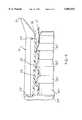
- FIG. 6is partial, enlarged, longitudinal, cross sectional view of the assembled quick connector of the present invention.
- first and second fluid conduits 12 and 14may be any conventional fluid carrying member, such as a plastic or rubber conduit, hose, etc.
- the fluid coupling 10includes first and second releasibly and sealingly interconnectable bodies 16 and 18, respectively, as well as a third connector body 20 which is releasably and sealingly connectable to the second body 18.
- the first body 16is formed of a suitable plastic, such as Nylon 6 and has a generally cylindrical configuration extending between opposed first and second ends 22 and 24, respectively.
- An axially extending bore denoted generally by reference number 26extends from the first end 22 to the second end 24.
- the bore 26is preferably formed with an inwardly extending taper which extends from a large diameter at the first end 22 of the first body 16 to a smaller diameter at the second end 24.
- Recesses 32 and 34are formed on opposite sides of the first body 16 for receiving latch arms, described hereafter, formed on the second body 16.
- a pair of apertures 36are formed in a cylindrical end 35 and form part of a latch arm receiver means, as described hereafter.
- a pair of opposed radially outwardly extending flanges 38are formed at the first end 22 of the first body 16.
- the second body 18is formed of a suitable plastic material, such as Nylon 6.
- the second body 18has opposed first and second ends 44 and 46, respectively.
- a generally cylindrical, tubular portion 48extends from the first end 44 and includes an annular recess 50 sized to receive a seal means, such an O-ring 52, as shown in FIG. 2.
- the first cylindrical portion 48merges into an enlarged, frusto-conical portion 53.
- a tubular shaft 55extends from the frusto-conical portion 53 to another frusto-conical portion 54 which has an outer peripheral edge 56 at the second end 46 of the second body 18.
- a generally cylindrical extension 60projects from the second end 46 of the second body 18 and has an internal bore axially aligned with respect to a similar bore 61 extending through the second body 18. At least one, and preferably, a plurality of radially enlarged projections 62 are formed externally on the extension 60. Preferably, the projections 62 comprise annular, radially outward extending projections as shown in FIG. 2.
- Latch meanspreferably in the form of a pair of opposed latch arms 66 and 68 are formed on the second body 18 and project generally axially from the second end 46 of the second body 18.
- the latch arms 66 and 68have a generally concave shape with an inwardly extending tab 70 adjacent an outer end 72.
- the outer end 72extends radially outward from a longitudinal axis of the second body 18 from the tab 70.
- the tabs 70are positioned to engage the apertures 36 in the first body 16 when the first and second bodies 16 and 18 are joined together.
- the latch arms 66 and 68slide along the recesses 32 and 34 in the first body 16 until the tabs 70 snap into the apertures 36.
- the outer end 72 of the latch arms 66 and 68may be urged outward by manual force or by means of a suitable release tool to disengage the tabs 70 from the apertures 36 so as to enable separation of the first and second bodies 16 and 18.
- the tapering bore 26 in the first body 16coacts with the projections 62 on the cylindrical extension 60 on the second body 18 to forcibly squeeze an end portion of the first conduit 12 situated therebetween as shown in FIG. 6.
- the third body 20includes a generally cylindrical portion 78 with opposed first and second ends 80 and 82, respectively.
- a bore 84extends through the cylindrical portion 78 between the first and second ends 80 and 82.
- the cylindrical portion 78is shown as being in the form of a 90° elbow. It will be understood that the cylindrical portion 78 of the third body 20 may also have a generally axially extending, linear shape.
- An end portion of the bore 84 at the first end 80 of the cylindrical portion 78is sized to securely receive the first end of the second conduit 14. Suitable means may be employed to fixedly couple the second conduit 14 in the bore 84.
- the second conduit 14is preferably solvent bonded in the bore 84 of the cylindrical portion 78.
- a pair of latch arms 86project axially from the second end 82 of the cylindrical portion 78.
- the latch arms 86are diametrically opposed and have a generally concave shape to define a portion of an annular bore sized to securely receive the frusto-conical portion 53 of the second body 18.
- a receiver means 90such as an aperture, is formed in each latch arm 86.
- An inwardly extending projection 92is formed in each latch arm 86 adjacent one edge of the aperture 90. The projections 92 are positioned to snap around and engage the peripheral edge on the frusto-conical portion 53 on the second body 18 to releasably interconnect the second and third bodies 18 and 20.
- the latch arms 86extend angularly inward with respect to the longitudinal axis of the tubular portion 78 of the third body 20 to increase spring force on the second body 18 so as to securely engage the projections 92 with the peripheral edge 56 on the second body 18 to provide increased pull out force resistance.
- a pair of guide members 94are disposed diametrically opposite each other and between the latch arms 86 and projects from the second end 82.
- the guide members 94have a generally concave shape.
- the support structure 100may be a vehicle cowl screen having an aperture 102 formed therein for receiving the tubular cylindrical portion 78 of the third body 20 therethrough.
- the second end 82 of the third body 20may have a generally collar-like shape to seat against one side of the support structure 100.
- At least one and preferably, a pair of resilient, outwardly extending latch members 88are carried externally on the cylindrical portion 78 and are designed to resiliently fold into close proximity with the cylindrical portion 78 as the third body 20 is inserted through the aperture 102 in the support structure 100 and then snap outward into engagement with one surface of the support structure 100 to lockingly mount the third body 20 to the support structure 100.
- the quick connector fluid coupling 10 described above and shown in FIGS. 1-4finds advantageous use in an automotive windshield washer/wiper system.
- the second conduit 14 extending from the third body 20may be connected to the washer fluid reservoir and pump in the vehicle engine compartment. This enables the pump, reservoir, conduit, and cowl screen to be manufactured as a single subassembly separate from the other vehicle components.
- the first conduit 12is mounted on the vehicle wiper arm such that the joined first and second bodies 16 and 18 enable a snap-in connection with the third body 20 when the wiper arm is mounted on the vehicle.
- the wiper arm subassemblycan be completed separate from the windshield washer fluid pump and reservoir subassembly.
- connection of the second and third bodies 18 and 20is simple and ergonomic due to the relatively larger diameter size than the small diameter, flexible conduits and connectors employed in prior wiper/washer systems. Further, the snap-in engagement of the latch arms 86 on the third body 20 into engagement with the edge on the frusto-conical portion 53 of the second body 18 provides a positive indication to the installer of full, sealed engagement of the second and third bodies 18 and 20.
- FIG. 5depicts an alternate embodiment of the second body 18 which enables the first and second bodies 16 and 18 to be used together as a fluid coupler for interconnecting two conduits in fluid flow communication.
- the second body 18is substantially identical to the embodiment shown in FIGS. 1-5 and described above except that the annular recess 50 and seal O-ring 52 are eliminated and replaced by means for securely and sealingly mounting an external conduit or tube 108 to the tubular cylindrical portion 48 of the second body 18.
- the mountingmay simply comprise suitably sizing the bore at the first end 44 of the tubular cylindrical portion 48 with an inner diameter to securely receive the conduit 108 therein, with the conduit 108 being fixedly joined thereto by means of solvent bonding.
- one or more radial projections or barbssimilar to the projections 62 on the extension 60 shown in FIG. 2, may be formed externally on the cylindrical portion 48 to mechanically retain the conduit 108 on the second body.
- a unique quick connector fluid couplingwhich is ideally suited for use in interconnecting a conduit connected to a vehicle windshield wiper arm and a separate conduit extending from the washer fluid supply reservoir to a connector mounted in the cowl screen of an automobile.
- the quick connectorprovides an easy, ergonomic connection thereby insuring that a complete, fully seated and sealed connection is made between the various connector components.
Landscapes
- Engineering & Computer Science (AREA)
- General Engineering & Computer Science (AREA)
- Mechanical Engineering (AREA)
- Quick-Acting Or Multi-Walled Pipe Joints (AREA)
Abstract
Description
Claims (13)
Priority Applications (1)
| Application Number | Priority Date | Filing Date | Title |
|---|---|---|---|
| US08/771,239US5882047A (en) | 1996-12-20 | 1996-12-20 | Quick connector fluid coupling |
Applications Claiming Priority (1)
| Application Number | Priority Date | Filing Date | Title |
|---|---|---|---|
| US08/771,239US5882047A (en) | 1996-12-20 | 1996-12-20 | Quick connector fluid coupling |
Publications (1)
| Publication Number | Publication Date |
|---|---|
| US5882047Atrue US5882047A (en) | 1999-03-16 |
Family
ID=25091169
Family Applications (1)
| Application Number | Title | Priority Date | Filing Date |
|---|---|---|---|
| US08/771,239Expired - LifetimeUS5882047A (en) | 1996-12-20 | 1996-12-20 | Quick connector fluid coupling |
Country Status (1)
| Country | Link |
|---|---|
| US (1) | US5882047A (en) |
Cited By (87)
| Publication number | Priority date | Publication date | Assignee | Title |
|---|---|---|---|---|
| US20030219977A1 (en)* | 2002-05-21 | 2003-11-27 | Christophe Pomarede | Reduced cross-contamination between chambers in a semiconductor processing tool |
| US6688654B2 (en)* | 2000-12-08 | 2004-02-10 | Newfrey Llc | One piece quick connector |
| GB2391582A (en)* | 2002-06-25 | 2004-02-11 | Hewlett Packard Development Co | Fan-securing device for use with a heat transfer device |
| US6796586B2 (en) | 2001-07-09 | 2004-09-28 | Twin Bay Medical, Inc. | Barb clamp |
| US20050082828A1 (en)* | 2003-09-12 | 2005-04-21 | Wicks Jeffrey C. | Releasable connection assembly for joining tubing sections |
| US20050082826A1 (en)* | 2003-10-17 | 2005-04-21 | Twin Bay Medical, Inc. | Barb clamp |
| US20050148955A1 (en)* | 2003-12-26 | 2005-07-07 | Medtronic Minimed, Inc. | Modular catheter system |
| US7090257B2 (en) | 2002-04-16 | 2006-08-15 | Twin Bay Medical, Inc. | Barb clamp |
| US20060208743A1 (en)* | 2005-03-16 | 2006-09-21 | Yoshimitsu Ishida | Connector device and checker |
| US20070181132A1 (en)* | 2006-02-06 | 2007-08-09 | Worley Brian D | Ventilator to tracheotomy tube coupling |
| US20080169646A1 (en)* | 2003-10-17 | 2008-07-17 | Twin Bay Medical, Inc. | Barb clamp with smooth bore |
| US20080175719A1 (en)* | 2006-04-14 | 2008-07-24 | Deka Products Limited Partnership | Fluid pumping systems, devices and methods |
| US20080216898A1 (en)* | 2007-02-27 | 2008-09-11 | Deka Products Limited Partnership | Cassette System Integrated Apparatus |
| US20080253427A1 (en)* | 2007-02-27 | 2008-10-16 | Deka Products Limited Partnership | Sensor Apparatus Systems, Devices and Methods |
| US7448653B2 (en) | 2005-06-10 | 2008-11-11 | Value Plastics, Inc. | Female connector for releasable coupling with a male connector defining a fluid conduit |
| US20090008331A1 (en)* | 2007-02-27 | 2009-01-08 | Deka Products Limited Partnership | Hemodialysis systems and methods |
| US20090095679A1 (en)* | 2007-02-27 | 2009-04-16 | Deka Products Limited Partnership | Hemodialysis systems and methods |
| US20090101549A1 (en)* | 2007-02-27 | 2009-04-23 | Deka Products Limited Partnership | Modular assembly for a portable hemodialysis system |
| US20090105629A1 (en)* | 2007-02-27 | 2009-04-23 | Deka Products Limited Partnership | Blood circuit assembly for a hemodialysis system |
| US20090179422A1 (en)* | 2003-10-17 | 2009-07-16 | Twin Bay Medical, Inc. | Barb Clamp with Smooth Bore |
| US20100013215A1 (en)* | 2003-10-17 | 2010-01-21 | Twin Bay Medical, Inc. | Barb Clamp with Collet Interlocks |
| US20100051529A1 (en)* | 2008-08-27 | 2010-03-04 | Deka Products Limited Partnership | Dialyzer cartridge mounting arrangement for a hemodialysis system |
| US20100056975A1 (en)* | 2008-08-27 | 2010-03-04 | Deka Products Limited Partnership | Blood line connector for a medical infusion device |
| US20100051551A1 (en)* | 2007-02-27 | 2010-03-04 | Deka Products Limited Partnership | Reagent supply for a hemodialysis system |
| US20100109319A1 (en)* | 2008-11-03 | 2010-05-06 | Tianjin Runshi Science Development Co., Ltd. | Pipe fittings with a locating claw |
| US20100140917A1 (en)* | 2008-12-05 | 2010-06-10 | Plastiflex Canada Inc. | Vacuum fitting connection |
| WO2010068529A1 (en)* | 2008-12-10 | 2010-06-17 | Illinois Tool Works Inc. | A cooling system for a combustion engine |
| US20100192686A1 (en)* | 2007-02-27 | 2010-08-05 | Deka Products Limited Partnership | Blood treatment systems and methods |
| US7806139B2 (en) | 2006-01-20 | 2010-10-05 | Value Plastics, Inc. | Fluid conduit coupling assembly having male and female couplers with integral valves |
| US20100253075A1 (en)* | 2009-04-02 | 2010-10-07 | Twin Bay Medical, Inc. | Sanitary Retainer |
| USD629894S1 (en) | 2008-07-03 | 2010-12-28 | Value Plastics, Inc. | Male body of connector for fluid tubing |
| USD630320S1 (en) | 2008-07-03 | 2011-01-04 | Value Plastics, Inc. | Connector for fluid tubing |
| USD634840S1 (en) | 2008-07-03 | 2011-03-22 | Value Plastics, Inc. | Female body of connector for fluid tubing |
| US20110105877A1 (en)* | 2009-10-30 | 2011-05-05 | Deka Products Limited Partnership | Apparatus and method for detecting disconnection of an intravascular access device |
| USD645547S1 (en) | 2007-11-19 | 2011-09-20 | Value Plastics, Inc. | Male quick connect fitting |
| USD649240S1 (en) | 2009-12-09 | 2011-11-22 | Value Plastics, Inc. | Male dual lumen bayonet connector |
| USD650478S1 (en) | 2009-12-23 | 2011-12-13 | Value Plastics, Inc. | Female dual lumen connector |
| USD652510S1 (en) | 2011-02-11 | 2012-01-17 | Value Plastics, Inc. | Connector for fluid tubing |
| USD652511S1 (en) | 2011-02-11 | 2012-01-17 | Value Plastics, Inc. | Female body of connector for fluid tubing |
| US20120043754A1 (en)* | 2010-08-23 | 2012-02-23 | Lg Chem, Ltd. | Connecting assembly |
| USD655393S1 (en) | 2009-06-23 | 2012-03-06 | Value Plastics, Inc. | Multi-port valve |
| USD663022S1 (en) | 2011-02-11 | 2012-07-03 | Nordson Corporation | Male body of connector for fluid tubing |
| US8235426B2 (en) | 2008-07-03 | 2012-08-07 | Nordson Corporation | Latch assembly for joining two conduits |
| US8273049B2 (en) | 2007-02-27 | 2012-09-25 | Deka Products Limited Partnership | Pumping cassette |
| US8353315B2 (en) | 2010-08-23 | 2013-01-15 | Lg Chem, Ltd. | End cap |
| US8393690B2 (en) | 2007-02-27 | 2013-03-12 | Deka Products Limited Partnership | Enclosure for a portable hemodialysis system |
| US8511309B2 (en) | 2006-02-06 | 2013-08-20 | Brian D. Worley | Ventilator to tracheotomy tube coupling |
| US20130317483A1 (en)* | 2012-05-24 | 2013-11-28 | Kimberly-Clark Worldwide, Inc. | Universal connector for drainage of bodily fluids |
| USD698440S1 (en) | 2011-07-29 | 2014-01-28 | Nordson Corporation | Connector for fluid tubing |
| USD699841S1 (en) | 2011-07-29 | 2014-02-18 | Nordson Corporation | Female body of connector for fluid tubing |
| USD699840S1 (en) | 2011-07-29 | 2014-02-18 | Nordson Corporation | Male body of connector for fluid tubing |
| US8758922B2 (en) | 2010-08-23 | 2014-06-24 | Lg Chem, Ltd. | Battery system and manifold assembly with two manifold members removably coupled together |
| USD709612S1 (en) | 2011-12-23 | 2014-07-22 | Nordson Corporation | Female dual lumen connector |
| US20140232108A1 (en)* | 2008-10-10 | 2014-08-21 | Deka Products Limited Partnership | Medium connector |
| US8920956B2 (en) | 2010-08-23 | 2014-12-30 | Lg Chem, Ltd. | Battery system and manifold assembly having a manifold member and a connecting fitting |
| US8974934B2 (en) | 2012-08-16 | 2015-03-10 | Lg Chem, Ltd. | Battery module |
| US9046205B2 (en) | 2009-12-09 | 2015-06-02 | Nordson Corporation | Fluid connector latches with profile lead-ins |
| US20160084419A1 (en)* | 2010-07-14 | 2016-03-24 | Hewlett-Packard Development Company, L.P. | Mounting apparatus and system thereof |
| WO2016079186A1 (en)* | 2014-11-20 | 2016-05-26 | Valeo Klimasysteme Gmbh | Subassembly comprising a flange and a test device |
| US9388929B2 (en) | 2009-12-09 | 2016-07-12 | Nordson Corporation | Male bayonet connector |
| US9464741B2 (en) | 2009-12-09 | 2016-10-11 | Nordson Corporation | Button latch with integrally molded cantilever springs |
| US9517295B2 (en) | 2007-02-27 | 2016-12-13 | Deka Products Limited Partnership | Blood treatment systems and methods |
| US9597442B2 (en) | 2007-02-27 | 2017-03-21 | Deka Products Limited Partnership | Air trap for a medical infusion device |
| USD785790S1 (en) | 2009-12-09 | 2017-05-02 | General Electric Company | Male dual lumen bayonet connector |
| US9724458B2 (en) | 2011-05-24 | 2017-08-08 | Deka Products Limited Partnership | Hemodialysis system |
| WO2018075142A1 (en)* | 2016-10-20 | 2018-04-26 | Emd Millipore Corporation | Valve protection and tube management device |
| USD838366S1 (en) | 2016-10-31 | 2019-01-15 | Nordson Corporation | Blood pressure connector |
| US10207048B2 (en) | 2001-05-18 | 2019-02-19 | Deka Products Limited Partnership | Infusion set for a fluid pump |
| US10238797B2 (en) | 2008-10-10 | 2019-03-26 | Deka Products Limited Partnership | Infusion pump assembly |
| US10314969B2 (en) | 2008-10-10 | 2019-06-11 | Deka Products Limited Partnership | Occlusion detection system and method |
| US10322229B2 (en) | 2008-10-10 | 2019-06-18 | Deka Products Limited Partnership | Multi-language / multi-processor infusion pump assembly |
| US10398835B2 (en) | 2008-10-10 | 2019-09-03 | Deka Products Limited Partnership | System and method for administering an infusible fluid |
| CN110234386A (en)* | 2017-01-05 | 2019-09-13 | 生命科技股份有限公司 | Compression collar for coupling a pipe to a pipe joint and method of use |
| US10500352B2 (en) | 2001-05-18 | 2019-12-10 | Deka Products Limited Partnership | Infusion pump assembly |
| US10537671B2 (en) | 2006-04-14 | 2020-01-21 | Deka Products Limited Partnership | Automated control mechanisms in a hemodialysis apparatus |
| US10583247B2 (en) | 2008-10-10 | 2020-03-10 | Deka Products Limited Partnership | Infusion pump assembly with a backup power supply |
| US10677342B2 (en) | 2018-07-09 | 2020-06-09 | Robert Bosch Mexico Sistemas Automotrices S.A. de C.V. | Gear housing including snap-fit connection between housing cover and gear shaft |
| US10711930B2 (en) | 2009-12-09 | 2020-07-14 | Nordson Corporation | Releasable connection assembly |
| US10765800B2 (en) | 2008-10-10 | 2020-09-08 | Deka Products Limited Partnership | Pump assembly with a removable cover assembly |
| US10869984B2 (en) | 2006-02-06 | 2020-12-22 | Lazarus Medical, L.L.C. | Ventilator to tracheotomy tube coupling |
| WO2021122020A1 (en)* | 2019-12-17 | 2021-06-24 | Voss Automotive Gmbh | Plug connector assembly |
| US11333282B2 (en)* | 2019-11-05 | 2022-05-17 | Diality Inc. | Locking connector |
| US11738130B2 (en) | 2008-01-23 | 2023-08-29 | Deka Products Limited Partnership | Fluid line autoconnect apparatus and methods for medical treatment system |
| US11752248B2 (en) | 2008-01-23 | 2023-09-12 | Deka Products Limited Partnership | Medical treatment system and methods using a plurality of fluid lines |
| US11833281B2 (en) | 2008-01-23 | 2023-12-05 | Deka Products Limited Partnership | Pump cassette and methods for use in medical treatment system using a plurality of fluid lines |
| GB2621357A (en)* | 2022-08-09 | 2024-02-14 | Salts Healthcare Ltd | An ostomy drainage system |
| US11964086B2 (en) | 2010-07-07 | 2024-04-23 | Deka Products Limited Partnership | Medical treatment system and methods using a plurality of fluid lines |
Citations (19)
| Publication number | Priority date | Publication date | Assignee | Title |
|---|---|---|---|---|
| US3964339A (en)* | 1975-05-19 | 1976-06-22 | Air Products And Chemicals, Inc. | End holders for handle bars |
| US4026581A (en)* | 1975-11-13 | 1977-05-31 | Lacrex Brevetti S.A. | Releasable coupling |
| US4123091A (en)* | 1977-11-21 | 1978-10-31 | Renal Systems, Inc. | Tube connector |
| US4451069A (en)* | 1982-08-09 | 1984-05-29 | Smith Investment Company | Quick connect fluid coupling |
| US4471978A (en)* | 1978-06-07 | 1984-09-18 | Dieter Kramer | Push-pull connecting system for pressure lines, brake-system lines in particular |
| US4577894A (en)* | 1983-08-01 | 1986-03-25 | Wake Harold E | Axial compression hose coupling |
| US4673200A (en)* | 1985-01-24 | 1987-06-16 | Ikeda Bussan Co., Ltd. | Fluid joint |
| US4790569A (en)* | 1987-01-12 | 1988-12-13 | The Gates Rubber Company | Reverse taper ring lock coupler and method |
| US4820288A (en)* | 1981-06-23 | 1989-04-11 | Terumo Kabushiki Kaisha | Connector for therapeutic tubing and medical solution bag device using the connector |
| US4826477A (en)* | 1986-09-19 | 1989-05-02 | Abiomed Cardiovascular, Inc. | Connector for blood handling systems |
| US4969879A (en)* | 1988-07-26 | 1990-11-13 | Gish Biomedical, Inc. | Body fluid interconnect |
| US5082315A (en)* | 1988-05-04 | 1992-01-21 | Rasmussen Gmbh | Hose coupling |
| US5366256A (en)* | 1994-02-18 | 1994-11-22 | Pruzin Michael J | Spring retainers for hose couplings |
| US5374088A (en)* | 1993-01-02 | 1994-12-20 | A. Raymond & Cie | Releasable plug-in connector for receiving a tubular plug-in part with a peripheral retaining rib |
| US5462313A (en)* | 1993-10-26 | 1995-10-31 | Form Rite Corporation | Quick connect coupling |
| US5511827A (en)* | 1994-04-18 | 1996-04-30 | Rasmussen Gmbh | Push-fit connector for joining two fluid lines |
| US5524939A (en)* | 1987-06-23 | 1996-06-11 | Proprietary Technology, Inc. | Apparatus for and method of attaching hoses and tubes to a fitting |
| US5568946A (en)* | 1994-12-14 | 1996-10-29 | Itt Corporation | Squeeze-to-release quick connector with snap-in retainer |
| US5573279A (en)* | 1994-01-03 | 1996-11-12 | Form Rite Corporation | Quick connect coupling |
- 1996
- 1996-12-20USUS08/771,239patent/US5882047A/ennot_activeExpired - Lifetime
Patent Citations (21)
| Publication number | Priority date | Publication date | Assignee | Title |
|---|---|---|---|---|
| US3964339A (en)* | 1975-05-19 | 1976-06-22 | Air Products And Chemicals, Inc. | End holders for handle bars |
| US4026581A (en)* | 1975-11-13 | 1977-05-31 | Lacrex Brevetti S.A. | Releasable coupling |
| US4123091A (en)* | 1977-11-21 | 1978-10-31 | Renal Systems, Inc. | Tube connector |
| US4471978A (en)* | 1978-06-07 | 1984-09-18 | Dieter Kramer | Push-pull connecting system for pressure lines, brake-system lines in particular |
| US4820288A (en)* | 1981-06-23 | 1989-04-11 | Terumo Kabushiki Kaisha | Connector for therapeutic tubing and medical solution bag device using the connector |
| US4451069A (en)* | 1982-08-09 | 1984-05-29 | Smith Investment Company | Quick connect fluid coupling |
| US4577894A (en)* | 1983-08-01 | 1986-03-25 | Wake Harold E | Axial compression hose coupling |
| US4673200A (en)* | 1985-01-24 | 1987-06-16 | Ikeda Bussan Co., Ltd. | Fluid joint |
| US4826477A (en)* | 1986-09-19 | 1989-05-02 | Abiomed Cardiovascular, Inc. | Connector for blood handling systems |
| US4790569A (en)* | 1987-01-12 | 1988-12-13 | The Gates Rubber Company | Reverse taper ring lock coupler and method |
| US5524939A (en)* | 1987-06-23 | 1996-06-11 | Proprietary Technology, Inc. | Apparatus for and method of attaching hoses and tubes to a fitting |
| US5568948A (en)* | 1987-06-23 | 1996-10-29 | Proprietary Technology, Inc. | Apparatus for attaching hoses and tubes to a fitting |
| US5544923A (en)* | 1987-06-23 | 1996-08-13 | Proprietary Technology, Inc. | Apparatus for attaching hoses and tubes to a fitting |
| US5082315A (en)* | 1988-05-04 | 1992-01-21 | Rasmussen Gmbh | Hose coupling |
| US4969879A (en)* | 1988-07-26 | 1990-11-13 | Gish Biomedical, Inc. | Body fluid interconnect |
| US5374088A (en)* | 1993-01-02 | 1994-12-20 | A. Raymond & Cie | Releasable plug-in connector for receiving a tubular plug-in part with a peripheral retaining rib |
| US5462313A (en)* | 1993-10-26 | 1995-10-31 | Form Rite Corporation | Quick connect coupling |
| US5573279A (en)* | 1994-01-03 | 1996-11-12 | Form Rite Corporation | Quick connect coupling |
| US5366256A (en)* | 1994-02-18 | 1994-11-22 | Pruzin Michael J | Spring retainers for hose couplings |
| US5511827A (en)* | 1994-04-18 | 1996-04-30 | Rasmussen Gmbh | Push-fit connector for joining two fluid lines |
| US5568946A (en)* | 1994-12-14 | 1996-10-29 | Itt Corporation | Squeeze-to-release quick connector with snap-in retainer |
Cited By (182)
| Publication number | Priority date | Publication date | Assignee | Title |
|---|---|---|---|---|
| US6688654B2 (en)* | 2000-12-08 | 2004-02-10 | Newfrey Llc | One piece quick connector |
| US10207048B2 (en) | 2001-05-18 | 2019-02-19 | Deka Products Limited Partnership | Infusion set for a fluid pump |
| US10967137B2 (en) | 2001-05-18 | 2021-04-06 | Deka Products Limited Partnership | Infusion pump assembly |
| US10500352B2 (en) | 2001-05-18 | 2019-12-10 | Deka Products Limited Partnership | Infusion pump assembly |
| US7357425B2 (en) | 2001-07-09 | 2008-04-15 | Twins Bay Medical, Inc. | Barb clamp |
| US6796586B2 (en) | 2001-07-09 | 2004-09-28 | Twin Bay Medical, Inc. | Barb clamp |
| US20050012332A1 (en)* | 2001-07-09 | 2005-01-20 | Werth Albert A. | Barb clamp |
| US7090257B2 (en) | 2002-04-16 | 2006-08-15 | Twin Bay Medical, Inc. | Barb clamp |
| US20030219977A1 (en)* | 2002-05-21 | 2003-11-27 | Christophe Pomarede | Reduced cross-contamination between chambers in a semiconductor processing tool |
| US20040047129A1 (en)* | 2002-06-25 | 2004-03-11 | Simon Glenn C. | Fan-securing device for use with a heat transfer device |
| GB2391582B (en)* | 2002-06-25 | 2005-08-17 | Hewlett Packard Development Co | Fan-securing device for use with a heat transfer device |
| US6879487B2 (en) | 2002-06-25 | 2005-04-12 | Hewlett-Packard Development Company, L.P. | Fan-securing device for use with a heat transfer device |
| GB2391582A (en)* | 2002-06-25 | 2004-02-11 | Hewlett Packard Development Co | Fan-securing device for use with a heat transfer device |
| US20050082828A1 (en)* | 2003-09-12 | 2005-04-21 | Wicks Jeffrey C. | Releasable connection assembly for joining tubing sections |
| US7878553B2 (en) | 2003-09-12 | 2011-02-01 | Value Plastics, Inc. | Releasable connection assembly for joining tubing sections |
| US20050082826A1 (en)* | 2003-10-17 | 2005-04-21 | Twin Bay Medical, Inc. | Barb clamp |
| US20090179422A1 (en)* | 2003-10-17 | 2009-07-16 | Twin Bay Medical, Inc. | Barb Clamp with Smooth Bore |
| US20080169646A1 (en)* | 2003-10-17 | 2008-07-17 | Twin Bay Medical, Inc. | Barb clamp with smooth bore |
| US8662542B2 (en) | 2003-10-17 | 2014-03-04 | Saint-Gobain Performance Plastics Corporation | Barb clamp with smooth bore |
| US20100013215A1 (en)* | 2003-10-17 | 2010-01-21 | Twin Bay Medical, Inc. | Barb Clamp with Collet Interlocks |
| US7922212B2 (en) | 2003-10-17 | 2011-04-12 | Twin Bay Medical, Inc. | Barb clamp with smooth bore |
| US20090212559A1 (en)* | 2003-10-17 | 2009-08-27 | Twin Bay Medical, Inc. | Barb Clamp with Smooth Bore |
| US7922213B2 (en) | 2003-10-17 | 2011-04-12 | Twin Bay Medical, Inc. | Barb clamp with smooth bore |
| US8256802B2 (en) | 2003-10-17 | 2012-09-04 | Twin Bay Medical, Inc. | Barb clamp with collet interlocks |
| WO2005065766A2 (en) | 2003-12-26 | 2005-07-21 | Medtronic Minimed, Inc. | Modular catheter system |
| US20050148955A1 (en)* | 2003-12-26 | 2005-07-07 | Medtronic Minimed, Inc. | Modular catheter system |
| US7846137B2 (en) | 2003-12-26 | 2010-12-07 | Medtronic Minimed, Inc. | Modular catheter system |
| US20110034903A1 (en)* | 2003-12-26 | 2011-02-10 | Medtronic Minimed, Inc. | Modular catheter system |
| US8025644B2 (en) | 2003-12-26 | 2011-09-27 | Medtronic Minimed, Inc. | Modular catheter system |
| WO2005065766A3 (en)* | 2003-12-26 | 2005-11-03 | Medtronic Minimed Inc | Modular catheter system |
| US7481463B2 (en)* | 2005-03-16 | 2009-01-27 | Tokai Rubber Industries, Inc. | Connector device and checker |
| US20060208743A1 (en)* | 2005-03-16 | 2006-09-21 | Yoshimitsu Ishida | Connector device and checker |
| US20080277924A1 (en)* | 2005-06-10 | 2008-11-13 | Value Plastics, Inc. | Female connector for releasable coupling with a male connector defining a fluid conduit |
| US7770939B2 (en) | 2005-06-10 | 2010-08-10 | Value Plastics, Inc. | Female connector for releasable coupling with a male connector defining a fluid conduit |
| US7448653B2 (en) | 2005-06-10 | 2008-11-11 | Value Plastics, Inc. | Female connector for releasable coupling with a male connector defining a fluid conduit |
| US8113546B2 (en) | 2005-06-10 | 2012-02-14 | Value Plastics, Inc. | Latching female fluid tubing coupler |
| US7806139B2 (en) | 2006-01-20 | 2010-10-05 | Value Plastics, Inc. | Fluid conduit coupling assembly having male and female couplers with integral valves |
| US8397756B2 (en) | 2006-01-20 | 2013-03-19 | Nordson Corporation | Fluid conduit couplers with depressible latch mechanism |
| US8511309B2 (en) | 2006-02-06 | 2013-08-20 | Brian D. Worley | Ventilator to tracheotomy tube coupling |
| US8485193B2 (en)* | 2006-02-06 | 2013-07-16 | Lazarus Medical, LLC | Ventilator to tracheotomy tube coupling |
| US10869984B2 (en) | 2006-02-06 | 2020-12-22 | Lazarus Medical, L.L.C. | Ventilator to tracheotomy tube coupling |
| US20070181132A1 (en)* | 2006-02-06 | 2007-08-09 | Worley Brian D | Ventilator to tracheotomy tube coupling |
| US8870549B2 (en) | 2006-04-14 | 2014-10-28 | Deka Products Limited Partnership | Fluid pumping systems, devices and methods |
| US8292594B2 (en) | 2006-04-14 | 2012-10-23 | Deka Products Limited Partnership | Fluid pumping systems, devices and methods |
| US10537671B2 (en) | 2006-04-14 | 2020-01-21 | Deka Products Limited Partnership | Automated control mechanisms in a hemodialysis apparatus |
| US20080175719A1 (en)* | 2006-04-14 | 2008-07-24 | Deka Products Limited Partnership | Fluid pumping systems, devices and methods |
| US8721884B2 (en) | 2007-02-27 | 2014-05-13 | Deka Products Limited Partnership | Hemodialysis systems and methods |
| US20090008331A1 (en)* | 2007-02-27 | 2009-01-08 | Deka Products Limited Partnership | Hemodialysis systems and methods |
| US11752244B2 (en) | 2007-02-27 | 2023-09-12 | Deka Products Limited Partnership | Blood circuit assembly for a hemodialysis system |
| US20080216898A1 (en)* | 2007-02-27 | 2008-09-11 | Deka Products Limited Partnership | Cassette System Integrated Apparatus |
| US20080253427A1 (en)* | 2007-02-27 | 2008-10-16 | Deka Products Limited Partnership | Sensor Apparatus Systems, Devices and Methods |
| US10851769B2 (en) | 2007-02-27 | 2020-12-01 | Deka Products Limited Partnership | Pumping cassette |
| US20090095679A1 (en)* | 2007-02-27 | 2009-04-16 | Deka Products Limited Partnership | Hemodialysis systems and methods |
| US8042563B2 (en) | 2007-02-27 | 2011-10-25 | Deka Products Limited Partnership | Cassette system integrated apparatus |
| US10500327B2 (en) | 2007-02-27 | 2019-12-10 | Deka Products Limited Partnership | Blood circuit assembly for a hemodialysis system |
| US10441697B2 (en) | 2007-02-27 | 2019-10-15 | Deka Products Limited Partnership | Modular assembly for a portable hemodialysis system |
| US20090101549A1 (en)* | 2007-02-27 | 2009-04-23 | Deka Products Limited Partnership | Modular assembly for a portable hemodialysis system |
| US10077766B2 (en) | 2007-02-27 | 2018-09-18 | Deka Products Limited Partnership | Pumping cassette |
| US9987407B2 (en) | 2007-02-27 | 2018-06-05 | Deka Products Limited Partnership | Blood circuit assembly for a hemodialysis system |
| US9951768B2 (en) | 2007-02-27 | 2018-04-24 | Deka Products Limited Partnership | Cassette system integrated apparatus |
| US9700660B2 (en) | 2007-02-27 | 2017-07-11 | Deka Products Limited Partnership | Pumping cassette |
| US9677554B2 (en) | 2007-02-27 | 2017-06-13 | Deka Products Limited Partnership | Cassette system integrated apparatus |
| US9649418B2 (en) | 2007-02-27 | 2017-05-16 | Deka Products Limited Partnership | Pumping cassette |
| US9603985B2 (en) | 2007-02-27 | 2017-03-28 | Deka Products Limited Partnership | Blood treatment systems and methods |
| US8246826B2 (en) | 2007-02-27 | 2012-08-21 | Deka Products Limited Partnership | Hemodialysis systems and methods |
| US20100192686A1 (en)* | 2007-02-27 | 2010-08-05 | Deka Products Limited Partnership | Blood treatment systems and methods |
| US8273049B2 (en) | 2007-02-27 | 2012-09-25 | Deka Products Limited Partnership | Pumping cassette |
| US9597442B2 (en) | 2007-02-27 | 2017-03-21 | Deka Products Limited Partnership | Air trap for a medical infusion device |
| US8317492B2 (en) | 2007-02-27 | 2012-11-27 | Deka Products Limited Partnership | Pumping cassette |
| US9555179B2 (en) | 2007-02-27 | 2017-01-31 | Deka Products Limited Partnership | Hemodialysis systems and methods |
| US8357298B2 (en) | 2007-02-27 | 2013-01-22 | Deka Products Limited Partnership | Hemodialysis systems and methods |
| US8393690B2 (en) | 2007-02-27 | 2013-03-12 | Deka Products Limited Partnership | Enclosure for a portable hemodialysis system |
| US9539379B2 (en) | 2007-02-27 | 2017-01-10 | Deka Products Limited Partnership | Enclosure for a portable hemodialysis system |
| US8409441B2 (en) | 2007-02-27 | 2013-04-02 | Deka Products Limited Partnership | Blood treatment systems and methods |
| US8425471B2 (en) | 2007-02-27 | 2013-04-23 | Deka Products Limited Partnership | Reagent supply for a hemodialysis system |
| US9535021B2 (en) | 2007-02-27 | 2017-01-03 | Deka Products Limited Partnership | Sensor apparatus systems, devices and methods |
| US8459292B2 (en) | 2007-02-27 | 2013-06-11 | Deka Products Limited Partnership | Cassette system integrated apparatus |
| US9517295B2 (en) | 2007-02-27 | 2016-12-13 | Deka Products Limited Partnership | Blood treatment systems and methods |
| US9302037B2 (en) | 2007-02-27 | 2016-04-05 | Deka Products Limited Partnership | Hemodialysis systems and methods |
| US8491184B2 (en) | 2007-02-27 | 2013-07-23 | Deka Products Limited Partnership | Sensor apparatus systems, devices and methods |
| US8499780B2 (en) | 2007-02-27 | 2013-08-06 | Deka Products Limited Partnership | Cassette system integrated apparatus |
| US20100051551A1 (en)* | 2007-02-27 | 2010-03-04 | Deka Products Limited Partnership | Reagent supply for a hemodialysis system |
| US8545698B2 (en) | 2007-02-27 | 2013-10-01 | Deka Products Limited Partnership | Hemodialysis systems and methods |
| US8562834B2 (en) | 2007-02-27 | 2013-10-22 | Deka Products Limited Partnership | Modular assembly for a portable hemodialysis system |
| US9272082B2 (en) | 2007-02-27 | 2016-03-01 | Deka Products Limited Partnership | Pumping cassette |
| US9115708B2 (en) | 2007-02-27 | 2015-08-25 | Deka Products Limited Partnership | Fluid balancing systems and methods |
| US9028691B2 (en) | 2007-02-27 | 2015-05-12 | Deka Products Limited Partnership | Blood circuit assembly for a hemodialysis system |
| US8992075B2 (en) | 2007-02-27 | 2015-03-31 | Deka Products Limited Partnership | Sensor apparatus systems, devices and methods |
| US8992189B2 (en) | 2007-02-27 | 2015-03-31 | Deka Products Limited Partnership | Cassette system integrated apparatus |
| US8985133B2 (en) | 2007-02-27 | 2015-03-24 | Deka Products Limited Partnership | Cassette system integrated apparatus |
| US8926294B2 (en) | 2007-02-27 | 2015-01-06 | Deka Products Limited Partnership | Pumping cassette |
| US8721879B2 (en) | 2007-02-27 | 2014-05-13 | Deka Products Limited Partnership | Hemodialysis systems and methods |
| US8888470B2 (en) | 2007-02-27 | 2014-11-18 | Deka Products Limited Partnership | Pumping cassette |
| US20090105629A1 (en)* | 2007-02-27 | 2009-04-23 | Deka Products Limited Partnership | Blood circuit assembly for a hemodialysis system |
| USD654573S1 (en) | 2007-11-19 | 2012-02-21 | Value Plastics, Inc. | Female quick connect fitting |
| USD645547S1 (en) | 2007-11-19 | 2011-09-20 | Value Plastics, Inc. | Male quick connect fitting |
| US12311086B2 (en) | 2008-01-23 | 2025-05-27 | Deka Products Limited Partnership | Pump cassette and methods for use in medical treatment system using a plurality of fluid lines |
| US11833281B2 (en) | 2008-01-23 | 2023-12-05 | Deka Products Limited Partnership | Pump cassette and methods for use in medical treatment system using a plurality of fluid lines |
| US11752248B2 (en) | 2008-01-23 | 2023-09-12 | Deka Products Limited Partnership | Medical treatment system and methods using a plurality of fluid lines |
| US11738130B2 (en) | 2008-01-23 | 2023-08-29 | Deka Products Limited Partnership | Fluid line autoconnect apparatus and methods for medical treatment system |
| US8235426B2 (en) | 2008-07-03 | 2012-08-07 | Nordson Corporation | Latch assembly for joining two conduits |
| USD634840S1 (en) | 2008-07-03 | 2011-03-22 | Value Plastics, Inc. | Female body of connector for fluid tubing |
| USD630320S1 (en) | 2008-07-03 | 2011-01-04 | Value Plastics, Inc. | Connector for fluid tubing |
| US8596688B2 (en) | 2008-07-03 | 2013-12-03 | Nordson Corporation | Latch assembly for joining two conduits |
| US8448994B2 (en) | 2008-07-03 | 2013-05-28 | Nordson Corporation | Latch assembly for joining two conduits |
| USD629894S1 (en) | 2008-07-03 | 2010-12-28 | Value Plastics, Inc. | Male body of connector for fluid tubing |
| US8771508B2 (en) | 2008-08-27 | 2014-07-08 | Deka Products Limited Partnership | Dialyzer cartridge mounting arrangement for a hemodialysis system |
| US20100056975A1 (en)* | 2008-08-27 | 2010-03-04 | Deka Products Limited Partnership | Blood line connector for a medical infusion device |
| US20100051529A1 (en)* | 2008-08-27 | 2010-03-04 | Deka Products Limited Partnership | Dialyzer cartridge mounting arrangement for a hemodialysis system |
| US10765800B2 (en) | 2008-10-10 | 2020-09-08 | Deka Products Limited Partnership | Pump assembly with a removable cover assembly |
| US10583247B2 (en) | 2008-10-10 | 2020-03-10 | Deka Products Limited Partnership | Infusion pump assembly with a backup power supply |
| US10398835B2 (en) | 2008-10-10 | 2019-09-03 | Deka Products Limited Partnership | System and method for administering an infusible fluid |
| US10322229B2 (en) | 2008-10-10 | 2019-06-18 | Deka Products Limited Partnership | Multi-language / multi-processor infusion pump assembly |
| US10314969B2 (en) | 2008-10-10 | 2019-06-11 | Deka Products Limited Partnership | Occlusion detection system and method |
| US10238797B2 (en) | 2008-10-10 | 2019-03-26 | Deka Products Limited Partnership | Infusion pump assembly |
| US10704714B2 (en)* | 2008-10-10 | 2020-07-07 | Deka Products Limited Partnership | Medium connector |
| US20140232108A1 (en)* | 2008-10-10 | 2014-08-21 | Deka Products Limited Partnership | Medium connector |
| US20100109319A1 (en)* | 2008-11-03 | 2010-05-06 | Tianjin Runshi Science Development Co., Ltd. | Pipe fittings with a locating claw |
| US20100140917A1 (en)* | 2008-12-05 | 2010-06-10 | Plastiflex Canada Inc. | Vacuum fitting connection |
| US20110232591A1 (en)* | 2008-12-10 | 2011-09-29 | Illinois Tool Works Inc. | Cooling system for a combustion engine |
| US9052046B2 (en) | 2008-12-10 | 2015-06-09 | Illinois Tool Works Inc. | Cooling system for a combustion engine |
| WO2010068529A1 (en)* | 2008-12-10 | 2010-06-17 | Illinois Tool Works Inc. | A cooling system for a combustion engine |
| US9605782B2 (en) | 2009-04-02 | 2017-03-28 | Saint-Gobain Performance Plastics Corporation | Sanitary retainer |
| US10619772B2 (en) | 2009-04-02 | 2020-04-14 | Saint-Gobain Performance Plastics Corporation | Sanitary retainer |
| US20100253075A1 (en)* | 2009-04-02 | 2010-10-07 | Twin Bay Medical, Inc. | Sanitary Retainer |
| USD655393S1 (en) | 2009-06-23 | 2012-03-06 | Value Plastics, Inc. | Multi-port valve |
| US20110105877A1 (en)* | 2009-10-30 | 2011-05-05 | Deka Products Limited Partnership | Apparatus and method for detecting disconnection of an intravascular access device |
| US10201650B2 (en) | 2009-10-30 | 2019-02-12 | Deka Products Limited Partnership | Apparatus and method for detecting disconnection of an intravascular access device |
| US9464741B2 (en) | 2009-12-09 | 2016-10-11 | Nordson Corporation | Button latch with integrally molded cantilever springs |
| US9388929B2 (en) | 2009-12-09 | 2016-07-12 | Nordson Corporation | Male bayonet connector |
| US9732891B2 (en) | 2009-12-09 | 2017-08-15 | General Electric Company | Male bayonet connector |
| US10001236B2 (en) | 2009-12-09 | 2018-06-19 | General Electric Company | Male bayonet connector |
| US9046205B2 (en) | 2009-12-09 | 2015-06-02 | Nordson Corporation | Fluid connector latches with profile lead-ins |
| US10711930B2 (en) | 2009-12-09 | 2020-07-14 | Nordson Corporation | Releasable connection assembly |
| USD785790S1 (en) | 2009-12-09 | 2017-05-02 | General Electric Company | Male dual lumen bayonet connector |
| USD649240S1 (en) | 2009-12-09 | 2011-11-22 | Value Plastics, Inc. | Male dual lumen bayonet connector |
| USD650478S1 (en) | 2009-12-23 | 2011-12-13 | Value Plastics, Inc. | Female dual lumen connector |
| US11964086B2 (en) | 2010-07-07 | 2024-04-23 | Deka Products Limited Partnership | Medical treatment system and methods using a plurality of fluid lines |
| US20160084419A1 (en)* | 2010-07-14 | 2016-03-24 | Hewlett-Packard Development Company, L.P. | Mounting apparatus and system thereof |
| US8469404B2 (en)* | 2010-08-23 | 2013-06-25 | Lg Chem, Ltd. | Connecting assembly |
| US20120043754A1 (en)* | 2010-08-23 | 2012-02-23 | Lg Chem, Ltd. | Connecting assembly |
| US8920956B2 (en) | 2010-08-23 | 2014-12-30 | Lg Chem, Ltd. | Battery system and manifold assembly having a manifold member and a connecting fitting |
| US8758922B2 (en) | 2010-08-23 | 2014-06-24 | Lg Chem, Ltd. | Battery system and manifold assembly with two manifold members removably coupled together |
| US8353315B2 (en) | 2010-08-23 | 2013-01-15 | Lg Chem, Ltd. | End cap |
| USD652510S1 (en) | 2011-02-11 | 2012-01-17 | Value Plastics, Inc. | Connector for fluid tubing |
| USD663022S1 (en) | 2011-02-11 | 2012-07-03 | Nordson Corporation | Male body of connector for fluid tubing |
| USD652511S1 (en) | 2011-02-11 | 2012-01-17 | Value Plastics, Inc. | Female body of connector for fluid tubing |
| US9724458B2 (en) | 2011-05-24 | 2017-08-08 | Deka Products Limited Partnership | Hemodialysis system |
| US12220507B2 (en) | 2011-05-24 | 2025-02-11 | Deka Products Limited Partnership | Blood treatment systems and methods |
| US10780213B2 (en) | 2011-05-24 | 2020-09-22 | Deka Products Limited Partnership | Hemodialysis system |
| USD699841S1 (en) | 2011-07-29 | 2014-02-18 | Nordson Corporation | Female body of connector for fluid tubing |
| USD699840S1 (en) | 2011-07-29 | 2014-02-18 | Nordson Corporation | Male body of connector for fluid tubing |
| USD712537S1 (en) | 2011-07-29 | 2014-09-02 | Nordson Corporation | Connector for fluid tubing |
| USD698440S1 (en) | 2011-07-29 | 2014-01-28 | Nordson Corporation | Connector for fluid tubing |
| USD709612S1 (en) | 2011-12-23 | 2014-07-22 | Nordson Corporation | Female dual lumen connector |
| US20130317483A1 (en)* | 2012-05-24 | 2013-11-28 | Kimberly-Clark Worldwide, Inc. | Universal connector for drainage of bodily fluids |
| US8974934B2 (en) | 2012-08-16 | 2015-03-10 | Lg Chem, Ltd. | Battery module |
| WO2016079186A1 (en)* | 2014-11-20 | 2016-05-26 | Valeo Klimasysteme Gmbh | Subassembly comprising a flange and a test device |
| WO2018075142A1 (en)* | 2016-10-20 | 2018-04-26 | Emd Millipore Corporation | Valve protection and tube management device |
| JP2019531893A (en)* | 2016-10-20 | 2019-11-07 | イー・エム・デイー・ミリポア・コーポレイシヨン | Valve protection and tube management equipment |
| US12090436B2 (en) | 2016-10-20 | 2024-09-17 | Emd Millipore Corporation | Valve protection and tube management device |
| US11602709B2 (en) | 2016-10-20 | 2023-03-14 | Emd Millipore Corporation | Valve protection and tube management device |
| USD964557S1 (en) | 2016-10-31 | 2022-09-20 | Nordson Corporation | Blood pressure connector |
| USD961070S1 (en) | 2016-10-31 | 2022-08-16 | Nordson Corporation | Blood pressure connector |
| USD964558S1 (en) | 2016-10-31 | 2022-09-20 | Nordson Corporation | Blood pressure connector |
| USD838366S1 (en) | 2016-10-31 | 2019-01-15 | Nordson Corporation | Blood pressure connector |
| USD967955S1 (en) | 2016-10-31 | 2022-10-25 | Nordson Corporation | Blood pressure connector |
| US11821553B2 (en) | 2017-01-05 | 2023-11-21 | Life Technologies Corporation | Methods of using compression collars for coupling a tube to a tube fitting |
| KR20190105231A (en)* | 2017-01-05 | 2019-09-16 | 라이프 테크놀로지스 코포레이션 | Compression collars and method of use for joining tubes to tube fittings |
| US11371634B2 (en)* | 2017-01-05 | 2022-06-28 | Life Technologies Corporation | Compression collars for coupling a tube to a tube fitting and methods of use |
| CN114734647A (en)* | 2017-01-05 | 2022-07-12 | 生命科技股份有限公司 | Compression collar for coupling pipe to fitting and method of use |
| US11821554B2 (en) | 2017-01-05 | 2023-11-21 | Life Technologies Corporation | Compression collars for coupling a tube to a tube fitting |
| US12398832B2 (en) | 2017-01-05 | 2025-08-26 | Life Technologies Corporation | Methods of using compression collars for coupling a tube to a tube fitting |
| USD1085364S1 (en) | 2017-01-05 | 2025-07-22 | Life Technologies Corporation | Compression collar for coupling a tube to a tube fitting |
| KR20220140643A (en)* | 2017-01-05 | 2022-10-18 | 라이프 테크놀로지스 코포레이션 | Compression collars for coupling a tube to a tube fitting and methods of use |
| CN114734647B (en)* | 2017-01-05 | 2024-10-29 | 生命科技股份有限公司 | Compression collar for coupling a pipe to a pipe joint and method of use |
| CN110234386A (en)* | 2017-01-05 | 2019-09-13 | 生命科技股份有限公司 | Compression collar for coupling a pipe to a pipe joint and method of use |
| US10677342B2 (en) | 2018-07-09 | 2020-06-09 | Robert Bosch Mexico Sistemas Automotrices S.A. de C.V. | Gear housing including snap-fit connection between housing cover and gear shaft |
| US11333282B2 (en)* | 2019-11-05 | 2022-05-17 | Diality Inc. | Locking connector |
| CN114761725A (en)* | 2019-12-17 | 2022-07-15 | 福士汽车配套部件责任有限公司 | Plug connector assembly |
| WO2021122020A1 (en)* | 2019-12-17 | 2021-06-24 | Voss Automotive Gmbh | Plug connector assembly |
| GB2621357A (en)* | 2022-08-09 | 2024-02-14 | Salts Healthcare Ltd | An ostomy drainage system |
Similar Documents
| Publication | Publication Date | Title |
|---|---|---|
| US5882047A (en) | Quick connector fluid coupling | |
| US5984378A (en) | Inline quick connector | |
| US6550815B2 (en) | Coaxial quick connector | |
| EP0796405B1 (en) | Squeeze-to-release quick connector with snap-in retainer | |
| CA2158521C (en) | Quick connect tube couplings | |
| RU2037723C1 (en) | Non-detachable device for sealed and quick joint of rigid pipe and flexible hose | |
| JP4837458B2 (en) | Quick connector | |
| EP0663558B1 (en) | Quick connect tubing connector | |
| US6447020B1 (en) | High-pressure integral tube coupling arrangements | |
| JPH0631668B2 (en) | Connector assembly | |
| EP1669655A1 (en) | Fluid coupling with dual function retention ring | |
| EP0529758A1 (en) | Quick connect coupling | |
| KR940006956Y1 (en) | Device for connecting thin tube | |
| JPH06123390A (en) | Quick pipe connector and connecting method thereof | |
| US5090745A (en) | Quick-connect connector for plastic tubes | |
| GB2226861A (en) | Connecting pipes and clusters comprising such pipes with push-fit connectors | |
| US6945422B2 (en) | In-tank fuel line quick connector assembly | |
| US4735440A (en) | Hose coupling | |
| WO2016014767A1 (en) | Universal tube fitting adaptable for different sized tubes | |
| US20050230968A1 (en) | Quick connector | |
| JPH10176779A (en) | Rapid connecting coupling | |
| EP0660907B1 (en) | Tubular assembly and method of making same | |
| JP2001200973A (en) | High pressure quick connector and assembling method therefor | |
| EP1055860A2 (en) | Improvements in or relating to pipe joints | |
| US7472931B2 (en) | Coupling assembly for tubing and hose connections |
Legal Events
| Date | Code | Title | Description |
|---|---|---|---|
| AS | Assignment | Owner name:ITT AUTOMOTIVE, INC., MICHIGAN Free format text:ASSIGNMENT OF ASSIGNORS INTEREST;ASSIGNORS:OSTRANDER, JAMES E.;PENDER, RICHARD;KLINGER, GARY O.;REEL/FRAME:008357/0063 Effective date:19961220 | |
| STCF | Information on status: patent grant | Free format text:PATENTED CASE | |
| FEPP | Fee payment procedure | Free format text:PAYOR NUMBER ASSIGNED (ORIGINAL EVENT CODE: ASPN); ENTITY STATUS OF PATENT OWNER: LARGE ENTITY | |
| FPAY | Fee payment | Year of fee payment:4 | |
| REMI | Maintenance fee reminder mailed | ||
| AS | Assignment | Owner name:DEUTSCHE BANK TRUST COMPANY AMERICAS, AS COLLATERA Free format text:SECURITY INTEREST;ASSIGNOR:COOPER-STANDARD AUTOMOTIVE INC.;REEL/FRAME:017564/0165 Effective date:20060406 | |
| FPAY | Fee payment | Year of fee payment:8 | |
| AS | Assignment | Owner name:COOPER-STANDARD AUTOMOTIVE INC., MICHIGAN Free format text:ASSET PURCHASE AGREEMENT;ASSIGNOR:ITT INDUSTRIES, INC.;REEL/FRAME:021817/0565 Effective date:20051204 | |
| FPAY | Fee payment | Year of fee payment:12 | |
| AS | Assignment | Owner name:BANK OF AMERICA, N.A., AS AGENT, ILLINOIS Free format text:SECURITY INTEREST;ASSIGNOR:COOPER STANDARD AUTOMOTIVE INC.;REEL/FRAME:032611/0388 Effective date:20140404 Owner name:DEUTSCHE BANK AG NEW YORK BRANCH, AS COLLATERAL AG Free format text:SECURITY INTEREST;ASSIGNOR:COOPER-STANDARD AUTOMOTIVE INC.;REEL/FRAME:032608/0179 Effective date:20130404 | |
| AS | Assignment | Owner name:COOPER-STANDARD AUTOMOTIVE, INC., MICHIGAN Free format text:RELEASE OF SECURITY INTEREST;ASSIGNOR:DEUTSCHE BANK TRUST COMPANY AMERICAS;REEL/FRAME:033687/0540 Effective date:20140711 | |
| AS | Assignment | Owner name:BANK OF AMERICA, N.A., AS AGENT, ILLINOIS Free format text:AMENDED AND RESTATED PATENT SECURITY AGREEMENT;ASSIGNOR:COOPER-STANDARD AUTOMOTIVE INC.;REEL/FRAME:040545/0476 Effective date:20161102 | |
| AS | Assignment | Owner name:COOPER-STANDARD AUTOMOTIVE INC., MICHIGAN Free format text:TERMINATION AND RELEASE OF SECURITY INTEREST PREVIOUSLY RECORDED AT REEL/FRAME (032608/0179);ASSIGNOR:DEUTSCHE BANK AG NEW YORK BRANCH, AS COLLATERAL AGENT;REEL/FRAME:062540/0124 Effective date:20230127 |