US5881182A - Adaptive process for removing streaks in digital images - Google Patents
Adaptive process for removing streaks in digital imagesDownload PDFInfo
- Publication number
- US5881182A US5881182AUS08/873,882US87388297AUS5881182AUS 5881182 AUS5881182 AUS 5881182AUS 87388297 AUS87388297 AUS 87388297AUS 5881182 AUS5881182 AUS 5881182A
- Authority
- US
- United States
- Prior art keywords
- pixel
- values
- image
- column
- offset
- Prior art date
- Legal status (The legal status is an assumption and is not a legal conclusion. Google has not performed a legal analysis and makes no representation as to the accuracy of the status listed.)
- Expired - Lifetime
Links
Images


Classifications
- H—ELECTRICITY
- H04—ELECTRIC COMMUNICATION TECHNIQUE
- H04N—PICTORIAL COMMUNICATION, e.g. TELEVISION
- H04N25/00—Circuitry of solid-state image sensors [SSIS]; Control thereof
- H04N25/60—Noise processing, e.g. detecting, correcting, reducing or removing noise
- H04N25/67—Noise processing, e.g. detecting, correcting, reducing or removing noise applied to fixed-pattern noise, e.g. non-uniformity of response
- H04N25/671—Noise processing, e.g. detecting, correcting, reducing or removing noise applied to fixed-pattern noise, e.g. non-uniformity of response for non-uniformity detection or correction
- H04N25/677—Noise processing, e.g. detecting, correcting, reducing or removing noise applied to fixed-pattern noise, e.g. non-uniformity of response for non-uniformity detection or correction for reducing the column or line fixed pattern noise
- G—PHYSICS
- G06—COMPUTING OR CALCULATING; COUNTING
- G06T—IMAGE DATA PROCESSING OR GENERATION, IN GENERAL
- G06T5/00—Image enhancement or restoration
- G06T5/20—Image enhancement or restoration using local operators
- H—ELECTRICITY
- H04—ELECTRIC COMMUNICATION TECHNIQUE
- H04N—PICTORIAL COMMUNICATION, e.g. TELEVISION
- H04N1/00—Scanning, transmission or reproduction of documents or the like, e.g. facsimile transmission; Details thereof
- H04N1/40—Picture signal circuits
- H04N1/409—Edge or detail enhancement; Noise or error suppression
Definitions
- the inventionrelates generally to the field of image processing, and in particular to an image processing method for removing streaks in digital images.
- the inventionis particularly useful in removing streaking in digital images that are acquired by a linear image sensing array, but may also be used to remove streaks in conventional film that are caused by the camera or processing equipment.
- Every detector in an electronic image sensormay have a different response function that relates the input intensity of light (or other electromagnetic radiation) to a pixel value in the digital image.
- This response functioncan change with time or operating temperature.
- Image sensorsare calibrated such that each detector has the same response for the same input intensity (illumination radiance).
- the calibrationis generally performed by illuminating each detector with a given radiance from a calibration lamp and then recording the signal from each detector to estimate the response function of the detector.
- the response function for each detectoris used to equalize the output of all of the detectors such that a uniform illumination across all of the detectors will produce a uniform output.
- FIG. 1shows a schematic of an image acquired by a linear image sensing arrays.
- the detector responseswill not be equalized and streaking 2 will appear in the image along the scan direction indicated by arrow A.
- streakingis generally referred to as banding, as illustrated at reference numeral 4.
- Streakingcan be seen in uniform areas of an image acquired by a linear detector and become very apparent when the contrast of the image is enhanced. Calibration differences between the red, green, and blue detectors of color imaging systems produce streaks of varying colors in the composite color image. These streaks not only reduce the aesthetic quality of digital images but can impact the interpretability of features in the images. Streaking also severely degrades the performance of pattern recognition and feature extraction algorithms.
- Streakscan be attenuated by reducing the contrast of the image or by blurring the image in a direction perpendicular to the streaking, but these methods degrade the quality of the overall image.
- Previously developed algorithms designed to remove the streaks while preserving the contrast and sharpness of the imageassume that the streaks do not change over time or that the pixels near each other are strongly correlated. In general these assumptions are not true. The responsivity of each detector, and hence the magnitudes of the streaks, changes over time, therefore methods that remove fixed patterns of streaks will not always work.
- FIG. 2ashows an image having streaks 2 and linear features 6 that are in the same direction as the streaks.
- FIG. 2bthe correction of the streaks 2 using the method taught by Garber remove the streaks 2, but results in additional streaking artifacts 8.
- the object of the present inventionis achieved in a method of removing columnar streaks from a digital image of the type in which it is assumed that pixels in a predetermined region near a given pixel are strongly related to each other and employing gain and offset values to compute streak removal information, by testing for a strong relation between the pixels in a predetermined region near a given pixel and computing streak removal information only if such a strong relationship exists, whereby image content that does not extend the full length of the image in the columnar direction will not be interpreted as a streak.
- the method of the present inventionadaptively removes streaking, as well as banding, in digital images without reducing the sharpness or contrast of the image. Streaking occurs in images output from linear scanners and is generally caused by differences in the responsivity of detectors or amplifiers.
- the method discloseddetects pixel locations in the image where pixel-to-pixel differences caused by streaking can be distinguished from normal variations in the scene data.
- a linear regressionis performed between each pair of adjacent pixels in a direction perpendicular to the streaking at the detected locations.
- a statistical outlier analysisis performed on the predicted values to remove the pixels that are not from the streaking.
- a second linear regressionis performed to calculate the slope and offset values. The slope is set to unity if it is not statistically different from unity, and the offset is set to zero if it is not statistically different from zero.
- the slope and offset valuesare then used to remove the streaking from the corresponding line of image data.
- This inventionadaptively removes streaking in a digital image by testing for a strong correlation between the pixels in a predetermined region and computing streak removal information only if such a strong relationship exists. This process will remove the residual streaks that appear even after a calibration is performed on the imaging sensor. This method does not reduce the contrast or the sharpness of the image.
- FIG. 1illustrates the streaking artifact in an image
- FIGS. 2(a)-2(b)illustrate the artifacts produced by methods that assume that pixels in a predetermined region near a given pixel are strongly related to each other;
- FIG. 3is a diagram showing an image processing chain using the present invention.
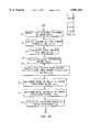
- FIG. 4made up of FIG. 4(a) and FIG. 4(b), is a flow chart of the streak removal process according to the present invention
- FIG. 5illustrates a digital mask that is used to test for pixels that are strongly related to each other in a predetermined region
- FIG. 6is a graph illustrating the linear regression with the two adjacent columns of image data, useful in describing the method of the present invention.
- the streak removal process of the present inventioncan be employed in a typical image processing chain, such as the one shown in FIG. 3.
- a digital sensor 10e.g. a linear scanner used in a camera system or a photographic scanner, outputs a digital image 12. If the detectors have gone through a calibration process, then the digital image 12 may go through a detector equalization process 14 to produce an equalized image 16. Both the digital image 12 and the equalized image 16 will contain streaks 2 as shown in FIG. 1.
- the digital image 12 or the equalized digital image 16is processed through the streak removal process 18 to produce a corrected digital image 20 that has the streaks removed.
- This corrected digital image 20is then processed through the nominal image processing chain and enhancements 22 to produce the final processed image 24. Without the streak removal process 18, the image processing and enhancements 22 may actually reduce the quality of the final processed image 24, especially if the digital image 12 is low in contrast or if the image processing and enhancements 22 includes a feature extraction algorithm.
- the original imagewas a photographic image having streaks or scratches resulting from the photographic, for example the scratches seen in old movie film
- the imagesmay be scanned in a high quality scanner and the streaks or scratches removed by the method of the present invention.
- the pixel at column coordinate x and row coordinate yhas a digital count value i(x,y). If d x is the detector for column x, then the response curve for detector d x in the digital sensor 10 can be modeled as a linear function of the input illumination radiance, thus
- I(x,y)is the intensity of the illumination radiance at location (x,y) in the image
- a xis the gain for detector d x
- b xis the bias for detector d x .
- Streaksoccur in the digital image 12 because adjacent detectors in the digital sensor 10 have different response curves.
- the difference ⁇ (x,y) between adjacent pixelsis given by
- i(x,y) and i(x+1,y)are proportional to the difference between the illumination radiance incident on the adjacent pixels, which is desired, and no streaks due to sensor calibration errors will be present.
- i(x,y)is just a linear transformation of i(x+1,) with a slope ⁇ a x and offset ⁇ b x .
- a testis performed for a strong relationship in spatial features between pixels and computes ⁇ a x and ⁇ b x only from those pixels where I(x,y) ⁇ I(x+1,y) thus preventing artifacts due to the processing to remove streaking from occurring.
- a schematic of the streak removal process 18 disclosed in this inventionis shown in FIG. 4. First two adjacent columns of image data are selected 30. Next, a column of pixel value pairs representing the pixel values of the adjacent pixels of the two columns is formed 32. Next a pair of columns of local mean values representing the mean values of pixels in an N pixel window for each of the adjacent columns of image data is formed 34.
- the local means ⁇ (x,y) and ⁇ (x+1,y)are calculated using ##EQU4## where N is the window length.
- a masksuch as the mask 35 shown in FIG. 5, is centered at pixel i(x,y) and convolved with the image. Pixels in the first and last ((N-1)/2 rows of the image will not be used to determine ⁇ a x and ⁇ b x .
- a local difference metric M(x,y)is calculated 36 that measures the similarity between local pixel regions.
- a difference metric based on the difference between the mean reduced valuesis given by ##EQU5##
- T Mis the difference metric threshold.
- T Mis the difference metric threshold.
- T Mis the difference metric threshold.
- T Mis defined by determining the largest magnitude difference of ⁇ (x,y) that is possible from calibration differences alone.
- Initial estimates of the slope and offsetare determined by performing a linear regression between i x (n) and i x+1 (n) to determine the regression line 39 in FIG. 6.
- the initial estimate of the slope, ⁇ a' xis calculated 40 by ##EQU6## where k is the total number of elements in i x (n).
- the initial estimate of the offset, ⁇ b' xis calculated 42 by ##EQU7##
- the slope ⁇ a x and offset ⁇ b x for Eq. (7)are determined by performing a second linear regression between i x (n) and i x+1 (n) after the statistical outliers 43 in FIG. 6 have been removed from the estimates of ⁇ a' x and ⁇ b' x .
- the standard error s e of the linear regressionis calculated 44.
- the statistical outliers 43will be defined as points lying outside a boundary 45 that is dependent on the standard error of estimate s e , given by ##EQU8## where
- ⁇ T Sare determined 46, these values are not statistical outliers.
- the outlier threshold T Sis proportional to s e and is typically set equal to 3s e .
- Two new columns of pixel values, i x (n) and its adjacent pixel i x+1 (n)are generated 48 for each row x, where only the j ⁇ k.
- the slope ⁇ a x and offset ⁇ b x for Eq. (7)are now determined 50 by ##EQU9##
- the final statistical tests performed 52are to determine if the slope ⁇ a x is statistically different from unity and the offset ⁇ b x is statistically different from zero. These tests are performed to ensure that the difference in the response curves estimated for detectors d x and d x+1 are statistically different. If they are not statistically different, then using the estimates for ⁇ a x .sbsb.-- 1 and ⁇ b x .sbsb.-- 0 may add streaking to the image rather than remove it, hence degrading the quality of the image rather than improving it.
- the t statisticis compared to the t distribution value t ⁇ /2 to determine if ⁇ a x is statistically different from unity. If t.sub. ⁇ a.sbsb.x ⁇ t ⁇ /2 then ⁇ a x is not statistically different from unity hence a value of 1 is used 54 for ⁇ a x in Eq. (7).
- the t statisticis given by ##EQU12## If t.sub. ⁇ b.sbsb.x ⁇ t ⁇ /2 then ⁇ b x is not statistically different from zero hence a value of 0 is used 56 for ⁇ b x in Eq. (7).
- the pixels i(x+1,y) in column xare modified by Eq. (7) to remove the steaks 58.
- the procedure outlined aboveis repeated for the next column of image data. This process is continued until all columns of the image data have been processed and the corrected digital image 20 is output.
Landscapes
- Engineering & Computer Science (AREA)
- Multimedia (AREA)
- Signal Processing (AREA)
- Physics & Mathematics (AREA)
- General Physics & Mathematics (AREA)
- Theoretical Computer Science (AREA)
- Image Processing (AREA)
Abstract
Description
i(x,y)=a.sub.x I(x,y)+b.sub.x, (1)
Δ(x,y)=i(x,y)-i(x+1,y)=a.sub.x I(x,y)+b.sub.x -a.sub.x+1 I(x+1,y)-b.sub.x+1, (2)
Δ(x,y)=i(x,y)-i(x+1,y)=a.sub.x I(x,y)-I(x+1,y)!, (3)
Δ(x,y)=i(x,y)-i(x+1,y)= a.sub.x -a.sub.x+1 !I(x,y)+ b.sub.x -b.sub.x+1 !, (4)
i(x,y)=Δa.sub.x i(x+1, y)+Δb.sub.x (6)
i'(x+1,y)≡Δa.sub.x i(x+1,y)+Δb.sub.x. (7)
ix(n)=Δa.sub.x i.sub.x+1 (n)+Δb.sub.x. (14)
APPENDIX A______________________________________* Subroutines Called:* Open.sub.-- Tiff.sub.-- Image* Read.sub.-- Tiff.sub.-- Image* Close.sub.-- Tiff.sub.-- image* Write.sub.-- Tiff.sub.-- Image2**************************************************************Implicit NoneInclude `/cm/include/imgio.inc`Integer*4 IMGioPtr, npixels, nlines, Bits, band, datatypeCharacter*50 inname, outnameCharacter*4 cstdev, cthresh, cc1, cmaxdiff, cconfa, cconfbReal*4 Input.sub.-- Image(:,:),Output.sub.-- Image(:,:), metric.sub.-- image(:,:),stdevAllocatable (Input.sub.-- Image, Output.sub.-- Image, metric.sub.-- image)Parameter (band=0)Integer*4 X, Y, z, carg, narg, iargc, L, K, i1, i2REAL*8 line1(2048), line2(2048), line1a(2048), line2a(2048), metric(2048)REAL*8 sum, sum1, sum2, sum11, sum22, sum12, cnt, sd, sumprod, maxdiffREAL*8 max, min, max0, min0, MSE, cl, s, si, confa, confb, ta, tb, bias, gainREAL*8 slope(2048), offset(2048), diff, linecnt, mean1, mean2, thresh************* Read command line arguments* carg = 1 narg = iargc() IF(carg .le. narg )THEN CALL getarg(carg,inname) carg = carg + 1 CALL getarg(carg,outname) carg = carg + 1 CALL getarg(carg,ccl) READ(ccl,*) cl carg = carg + 1 CALL getarg(carg,cmaxdiff) READ(cmaxdiff,*)maxdiff carg = carg + 1 CALL getarg(carg,cstdev) READ(cstdev,*)stdev carg = carg + 1 CALL getarg(carg,cthresh) READ(cthresh,*)thresh carg = carg + 1 CALL getarg(carg,cconfa) READ(cconfa,*) confa carg = carg + 1 CALL getarg(carg,cconfb) READ(cconfb,*)confb ELSE WRITE(6,*)`Usage: remove.sub.-- cal input.sub.-- file output.sub.--filewindow.sub.-- size maxdiff + stdev.sub.-- coeff Metric.sub.-- thresholdslope.sub.-- confoffset.sub.-- conf` goto 999 ENDIF Write(6,*) `RUNNING REMOVE CALIBRATION NOISE ROUTINE` write(6,*) `*** Only works on 2k or smaller images ***` Write(6,*) `raw input filename =`,inname Write(6,*) `output filename =`,outname Write(6,*) `window size =`,cl Write(6,*) `maximum difference =`,maxdiff Write(6,*) `outlier stdev coefficient =`,stdev Write(6,*) `MSE threshold =`,thresh Write(6,*) `slope confidence t value =`,confa Write(6,*) `offset confidence t vatue =`,confb************* Read input imagery - pixel & line sizes* CALL Open.sub.-- Tiff.sub.-- Image(inname,IMGioPtr,npixels,nlines,Bits) ALLOCATE (Input.sub.-- Image(npixels, nines)) ALLOCATE (Output.sub.-- Image(npixels, nlines)) ALLOCATE (metric.sub.-- Image(npixels, nlines)) CALL Read.sub.-- Tiff.sub.-- Image(IMGioPtr,Input.sub.-- Image,npixels,nlines,Band) CALL Close.sub.-- Tiff.sub.-- Image(IMGioPtr)************ Determine mean-square error between line segments after bias is removed DO X = 1, npixels-1 DO Y = int(cl/2)+1, nlines-int(cl/2) mean1=0 mean2=0 do z=-int(cl/2),int(cl/2) meanl=mean1+input.sub.-- image(x,y+z)/cl mean2=mean2+input.sub.-- image(x+1,y+z)/cl enddo MSE=0 do z=-int(cl/2),int(cl/2) MSE=MSE+((input.sub.-- image(x,y+z)-mean1)-(input.sub.-- image(x+ 1,y+z)-mean2))**2 enddo metric.sub.-- image(x,y)=sqrt(MSE) enddo enddo************* Determine slope and offset to remove streaks************ Use only those points that have a low MSE (high correlation) between lines* DO X = 1, npixels-1 linecnt = 0 slope(x)= 1 offset(x)=0 DO Y = int(cl/2)+1, nlines-int(cl/2) diff = input.sub.-- image(X+1,Y) - input.sub.-- image(X,Y) IF(metric.sub.-- image(x,y).le.thresh.and.abs(diff).le.maxdiff)then linecnt = linecnt + 1 line1(linecnt)=input.sub.-- image(x,y) line2(linecnt)=input.sub.-- image(x+1,y) ENDIF ENDDO if(linecnt.gt.2)then sum1 = 0.0 sum2 = 0.0 sum12 = 0.0 sum22 = 0.0 sum11 = 0.0 DO Y = 1, linecnt sum1 = sum1 + line1(y) sum2 = sum2 + line2(y) sum12 = sum12 + line1(y)*line2(y) sum11 = sum11 + line1(y)**2 sum22 = sum22 + line2(y)**2 ENDDO slope(x)=(linecnt*sum12-sum1*sum2)/(linecnt*sum22-sum2**2) offset(x)=(sum1-stope(x)*sum2)/linecnt* calculate standard error sum = 0.0 DO Y = 1, linecnt sum = sum + (line1(y)-slope(x)*line2(y)-offset(x))**2 ENDDO sd = sqrt(sum/(linecnt-2))* throw away outliers to improve calculation cnt = 0.0 DO Y = 1,linecnt IF(abs(line1(y)-slope(x)*line2(y)-offset(x)).le.(stdev*sd))THEN cnt = cnt + 1 line1a(cnt)=line1(y) line2a(cnt)=line2(y) ENDIF ENDDO if(cnt.gt.2)then linecnt=cnt sum1 = 0.0 sum2 = 0.0 sum12 = 0.0 sum22 = 0.0 sum11 = 0.0 DO Y = 1,cnt sum1 = sum1 + line1a(y) sum2 = sum2 + line2a(y) sum12 = sum12 + line1a(y)*line2a(y) sum11 = sum11 + line1a(y)**2 sum22 = sum22 + line2a(y)**2 ENDDO slope(x)=(cnt*sum2-sum1*sum2)/(cnt*sum22-sum2**2) offset(x)=(sum1-slope(x)*sum2)/cnt endif s=sqrt(abs(sum11-sum1**2/linecnt-slope(x)*(sum12- sum1*sum2/linecnt))/(linecnt-2)) si=sqrt(abs(sum22-sum2**2/linecrt)) ta=si*abs(slope(x)-1)/s tb=si*abs(offset(x)-0)/s/sqrt(sum22/cnt) if(ta.lt.confa)then slope(x)=1 offset(x)=(sum1-slope(x)*sum2)/cnt endif if(tb.lt.confb)offset(x)=0 endifENDDO************* remove calibration differences* DO Y = 1,nlines output.sub.-- image(1,y)=input.sub.-- image(1,y) ENDDO bias=0 gain=1 DO X = 1, npixels-1 bias=bias+offset(x) gain=gain*slope(x) DO Y = 1, nlines output.sub.-- image(x+1,y)=gain*input.sub.-- image(x+1,y)+bias ENDDO ENDDO************* DRA to avoid clipping* min = 10000 max = -10000 DO Y = 1, nlines DO X = 1, npixels IF(output.sub.-- image(X,Y).lt.min)min = output.sub.-- image(X,Y) IF(output.sub.-- image(X,Y).gt.max)max = output.sub.-- image(X,Y) ENDDO ENDDO max0=2047 min0=0 DO Y = 1, nlines DO X = 1, npixels output.sub.-- image(X,Y) = NINT((max0-min0)*(output.sub.-- image(X,Y)-1min)/(max-min)+min0) ENDDO ENDDO************* Write output image* Datatype = 7 write(6,*)` ` write(6,*)`Writing Output Imagery` write(6,*)` ` Call Write.sub.-- Tiff.sub.-- Image2( Outname, Output.sub.-- Image,NPixels, + Nlines, Datatype, Band, bits) goto 999************* END - OF - ROUTINE*999 END______________________________________
______________________________________PARTS LIST______________________________________2 streaks4 banding6scene variation 8image artifact 10digital sensor 12digital image 14detector equalization 16 equalizedimage 18streak removal process 20 correcteddigital image 22 image processing andenhancements 24 final processedimage 30 selecting two adjacent columns of pixels step32 create two columns of adjacent pixel values step34 calculate local means step35 mask used fortesting pixel relationship 36 calculate local differencemetric step 38 remove pixel values from columns of pixel values that exceed thresholds step39 line from linear regression40 determine initial estimate of slope step42 determine initial estimate of offsetstep 43statistical outliers 44 calculate standard error oflinear regression step 45 statistical outlier boundary46 determine statistical outliers step48 remove statistical outliers from columns of pixel values step50 determine new estimate of slope and offset step52 determine t statistics for slope and offset step54 set slope to unity if not statistically different fromunity step 56 set offset to zero if not statistically different from zerostep 58 remove streaking using slope and offset values step______________________________________
Claims (3)
Priority Applications (1)
| Application Number | Priority Date | Filing Date | Title |
|---|---|---|---|
| US08/873,882US5881182A (en) | 1997-05-12 | 1997-05-12 | Adaptive process for removing streaks in digital images |
Applications Claiming Priority (1)
| Application Number | Priority Date | Filing Date | Title |
|---|---|---|---|
| US08/873,882US5881182A (en) | 1997-05-12 | 1997-05-12 | Adaptive process for removing streaks in digital images |
Publications (1)
| Publication Number | Publication Date |
|---|---|
| US5881182Atrue US5881182A (en) | 1999-03-09 |
Family
ID=25362520
Family Applications (1)
| Application Number | Title | Priority Date | Filing Date |
|---|---|---|---|
| US08/873,882Expired - LifetimeUS5881182A (en) | 1997-05-12 | 1997-05-12 | Adaptive process for removing streaks in digital images |
Country Status (1)
| Country | Link |
|---|---|
| US (1) | US5881182A (en) |
Cited By (49)
| Publication number | Priority date | Publication date | Assignee | Title |
|---|---|---|---|---|
| US5987156A (en)* | 1996-11-25 | 1999-11-16 | Lucent Technologies | Apparatus for correcting fixed column noise in images acquired by a fingerprint sensor |
| US6296387B1 (en)* | 1998-11-30 | 2001-10-02 | Commissariat A L'energie Atomique | Method for correcting image defects from a matrix-type X or γ-ray detector |
| US6304826B1 (en)* | 1999-02-05 | 2001-10-16 | Syscan, Inc. | Self-calibration method and circuit architecture of image sensor |
| US20010041022A1 (en)* | 2000-02-11 | 2001-11-15 | Eric Edwards | System and method for editing digital images |
| US6393161B1 (en)* | 1999-04-26 | 2002-05-21 | Xerox Corporation | Software system for minimizing image defects in a hard-copy input scanner |
| US20020114533A1 (en)* | 2000-12-14 | 2002-08-22 | Eastman Kodak Company | Adaptive process for removing streaks in multi-band digital images |
| US20030012452A1 (en)* | 2001-07-06 | 2003-01-16 | Jasc Software, Inc. | Assisted scratch removal |
| US20030018709A1 (en)* | 2001-07-20 | 2003-01-23 | Audible Magic | Playlist generation method and apparatus |
| US6646681B1 (en)* | 1999-04-14 | 2003-11-11 | Intel Corporation | Method for reducing row noise from images |
| US20040032510A1 (en)* | 2001-09-13 | 2004-02-19 | Regis Guillemaud | Method for determining imaging sensor reference image |
| US20040096099A1 (en)* | 2002-11-19 | 2004-05-20 | Realtek Semiconductor Corp. | Apparatus for reducing zipper of image and method thereof |
| US6757027B1 (en) | 2000-02-11 | 2004-06-29 | Sony Corporation | Automatic video editing |
| US20040163106A1 (en)* | 2003-02-01 | 2004-08-19 | Audible Magic, Inc. | Method and apparatus to identify a work received by a processing system |
| US6870959B1 (en)* | 1999-10-07 | 2005-03-22 | Hewlett-Packard Development Company, L.P. | Method for automatic removal of vertical streaks by modifying image data associated with non-homogenous image elements |
| US6952489B1 (en)* | 2000-09-29 | 2005-10-04 | Hewlett-Packard Development Company, L.P. | Fingerprint verification method having band detection |
| EP1596568A1 (en)* | 2004-05-14 | 2005-11-16 | Xerox Corporation | Systems and methods for streak detecion in image array scanning using overdetermined scanners and column filtering |
| US6993719B1 (en) | 2000-02-11 | 2006-01-31 | Sony Corporation | System and method for animated character photo-editing interface and cross-platform education icon |
| US20060034177A1 (en)* | 2004-07-28 | 2006-02-16 | Audible Magic Corporation | System for distributing decoy content in a peer to peer network |
| US7034874B1 (en)* | 2003-03-17 | 2006-04-25 | Biomorphic Vlsi, Inc | Automatic bad pixel correction in image sensors |
| US20060119904A1 (en)* | 2002-01-14 | 2006-06-08 | Transpacific Ip, Ltd. | Method of effacing zipper image |
| US20060170990A1 (en)* | 2005-01-17 | 2006-08-03 | Canon Kabushiki Kaisha | Image reading apparatus and method for controlling the same |
| US20070035787A1 (en)* | 2001-10-23 | 2007-02-15 | Transpacific Ip, Ltd. | Method of compensating a zipper image by a K-value and a method of calculating a K-value |
| US20070126893A1 (en)* | 2005-12-05 | 2007-06-07 | Eastman Kodak Company | Method for detecting streaks in digital images |
| US20070127840A1 (en)* | 2005-12-07 | 2007-06-07 | Lexmark International, Inc. | Method for removing streaks from a scanned image |
| US7262778B1 (en) | 2000-02-11 | 2007-08-28 | Sony Corporation | Automatic color adjustment of a template design |
| US20080141379A1 (en)* | 2001-04-05 | 2008-06-12 | Audible Magic Corporation | Copyright detection and protection system and method |
| CN100399792C (en)* | 2002-12-05 | 2008-07-02 | 瑞昱半导体股份有限公司 | Method and device for removing zipper-like blur of boundary image |
| US7477781B1 (en) | 2002-10-10 | 2009-01-13 | Dalsa Corporation | Method and apparatus for adaptive pixel correction of multi-color matrix |
| US20090021611A1 (en)* | 2006-03-24 | 2009-01-22 | Nikon Corporation | Signal processing method, signal processing system, coefficient generating device, and digital camera |
| US20090031326A1 (en)* | 2007-07-27 | 2009-01-29 | Audible Magic Corporation | System for identifying content of digital data |
| US20090192640A1 (en)* | 2001-07-10 | 2009-07-30 | Wold Erling H | Method and apparatus for identifying an unknown work |
| US20090240361A1 (en)* | 2000-11-03 | 2009-09-24 | Wold Erling H | Method and apparatus for creating a unique audio signature |
| US20100220193A1 (en)* | 2009-03-02 | 2010-09-02 | Flir Systems, Inc. | Systems and methods for processing infrared images |
| EP2375721A1 (en)* | 2010-04-09 | 2011-10-12 | Snell Limited | Repairing scratch impairments to an image |
| US8199651B1 (en) | 2009-03-16 | 2012-06-12 | Audible Magic Corporation | Method and system for modifying communication flows at a port level |
| US20130194463A1 (en)* | 2010-10-21 | 2013-08-01 | Canon Kabushiki Kaisha | Image processing apparatus and control method thereof |
| US20140320496A1 (en)* | 2011-05-19 | 2014-10-30 | Foveon, Inc. | Methods for Reducing Row and Column Patterns in a Digital Image |
| US9007491B2 (en) | 2010-10-21 | 2015-04-14 | Canon Kabushiki Kaisha | Image processing apparatus and control method thereof |
| US9049468B2 (en) | 2000-02-17 | 2015-06-02 | Audible Magic Corporation | Method and apparatus for identifying media content presented on a media playing device |
| US9081778B2 (en) | 2012-09-25 | 2015-07-14 | Audible Magic Corporation | Using digital fingerprints to associate data with a work |
| US9208542B2 (en) | 2009-03-02 | 2015-12-08 | Flir Systems, Inc. | Pixel-wise noise reduction in thermal images |
| US9235876B2 (en) | 2009-03-02 | 2016-01-12 | Flir Systems, Inc. | Row and column noise reduction in thermal images |
| US9237284B2 (en) | 2009-03-02 | 2016-01-12 | Flir Systems, Inc. | Systems and methods for processing infrared images |
| US9756264B2 (en) | 2009-03-02 | 2017-09-05 | Flir Systems, Inc. | Anomalous pixel detection |
| US9843742B2 (en) | 2009-03-02 | 2017-12-12 | Flir Systems, Inc. | Thermal image frame capture using de-aligned sensor array |
| US9948872B2 (en) | 2009-03-02 | 2018-04-17 | Flir Systems, Inc. | Monitor and control systems and methods for occupant safety and energy efficiency of structures |
| CN109919852A (en)* | 2018-12-31 | 2019-06-21 | 中国科学院软件研究所 | A roof viewing angle correction method for optical remote sensing images |
| US11113791B2 (en) | 2017-01-03 | 2021-09-07 | Flir Systems, Inc. | Image noise reduction using spectral transforms |
| US20210350505A1 (en)* | 2020-05-05 | 2021-11-11 | Realtek Semiconductor Corp. | Image debanding method |
Citations (5)
| Publication number | Priority date | Publication date | Assignee | Title |
|---|---|---|---|---|
| US4329709A (en)* | 1979-10-03 | 1982-05-11 | Hitachi, Ltd. | Solid-state color imaging device |
| US4556911A (en)* | 1983-03-23 | 1985-12-03 | Hitachi, Ltd. | Method and apparatus for driving a solid state camera |
| US4597014A (en)* | 1983-01-14 | 1986-06-24 | Asahi Kogaku Kogyo Kabushiki Kaisha | Solid-state image pickup device |
| US4608608A (en)* | 1983-11-30 | 1986-08-26 | Hitachi, Ltd. | Solid-state imaging system with smear suppression circuits |
| US5065444A (en)* | 1988-02-08 | 1991-11-12 | Northrop Corporation | Streak removal filtering method and apparatus |
- 1997
- 1997-05-12USUS08/873,882patent/US5881182A/ennot_activeExpired - Lifetime
Patent Citations (5)
| Publication number | Priority date | Publication date | Assignee | Title |
|---|---|---|---|---|
| US4329709A (en)* | 1979-10-03 | 1982-05-11 | Hitachi, Ltd. | Solid-state color imaging device |
| US4597014A (en)* | 1983-01-14 | 1986-06-24 | Asahi Kogaku Kogyo Kabushiki Kaisha | Solid-state image pickup device |
| US4556911A (en)* | 1983-03-23 | 1985-12-03 | Hitachi, Ltd. | Method and apparatus for driving a solid state camera |
| US4608608A (en)* | 1983-11-30 | 1986-08-26 | Hitachi, Ltd. | Solid-state imaging system with smear suppression circuits |
| US5065444A (en)* | 1988-02-08 | 1991-11-12 | Northrop Corporation | Streak removal filtering method and apparatus |
Cited By (113)
| Publication number | Priority date | Publication date | Assignee | Title |
|---|---|---|---|---|
| US5987156A (en)* | 1996-11-25 | 1999-11-16 | Lucent Technologies | Apparatus for correcting fixed column noise in images acquired by a fingerprint sensor |
| US6296387B1 (en)* | 1998-11-30 | 2001-10-02 | Commissariat A L'energie Atomique | Method for correcting image defects from a matrix-type X or γ-ray detector |
| US6304826B1 (en)* | 1999-02-05 | 2001-10-16 | Syscan, Inc. | Self-calibration method and circuit architecture of image sensor |
| US6646681B1 (en)* | 1999-04-14 | 2003-11-11 | Intel Corporation | Method for reducing row noise from images |
| US6393161B1 (en)* | 1999-04-26 | 2002-05-21 | Xerox Corporation | Software system for minimizing image defects in a hard-copy input scanner |
| US6870959B1 (en)* | 1999-10-07 | 2005-03-22 | Hewlett-Packard Development Company, L.P. | Method for automatic removal of vertical streaks by modifying image data associated with non-homogenous image elements |
| US6993719B1 (en) | 2000-02-11 | 2006-01-31 | Sony Corporation | System and method for animated character photo-editing interface and cross-platform education icon |
| US8049766B2 (en) | 2000-02-11 | 2011-11-01 | Sony Corporation | Automatic color adjustment of a template design |
| US20010041022A1 (en)* | 2000-02-11 | 2001-11-15 | Eric Edwards | System and method for editing digital images |
| US7843464B2 (en) | 2000-02-11 | 2010-11-30 | Sony Corporation | Automatic color adjustment of template design |
| US8184124B2 (en) | 2000-02-11 | 2012-05-22 | Sony Corporation | Automatic color adjustment of a template design |
| US6757027B1 (en) | 2000-02-11 | 2004-06-29 | Sony Corporation | Automatic video editing |
| US8345062B2 (en) | 2000-02-11 | 2013-01-01 | Sony Corporation | Automatic color adjustment of a template design |
| US20070291049A1 (en)* | 2000-02-11 | 2007-12-20 | Sony Corporation | Automatic Color Adjustment of a Template Design |
| US7710436B2 (en) | 2000-02-11 | 2010-05-04 | Sony Corporation | Automatic color adjustment of a template design |
| US7136528B2 (en) | 2000-02-11 | 2006-11-14 | Sony Corporation | System and method for editing digital images |
| US7262778B1 (en) | 2000-02-11 | 2007-08-28 | Sony Corporation | Automatic color adjustment of a template design |
| US7538776B2 (en) | 2000-02-11 | 2009-05-26 | Sony Corporation | Automatic color adjustment of a template design |
| US20070058886A1 (en)* | 2000-02-11 | 2007-03-15 | Eric Edwards | System and method for editing digital images |
| US20110069083A1 (en)* | 2000-02-11 | 2011-03-24 | Sony Corporation | Automatic color adjustment of a template design |
| US7349578B2 (en) | 2000-02-11 | 2008-03-25 | Sony Corporation | System and method for editing digital images |
| US9049468B2 (en) | 2000-02-17 | 2015-06-02 | Audible Magic Corporation | Method and apparatus for identifying media content presented on a media playing device |
| US6952489B1 (en)* | 2000-09-29 | 2005-10-04 | Hewlett-Packard Development Company, L.P. | Fingerprint verification method having band detection |
| US20090240361A1 (en)* | 2000-11-03 | 2009-09-24 | Wold Erling H | Method and apparatus for creating a unique audio signature |
| US8086445B2 (en) | 2000-11-03 | 2011-12-27 | Audible Magic Corporation | Method and apparatus for creating a unique audio signature |
| US6912322B2 (en) | 2000-12-14 | 2005-06-28 | Itt Manufacturing Enterprises Inc. | Adaptive process for removing streaks in multi-band digital images |
| US20020114533A1 (en)* | 2000-12-14 | 2002-08-22 | Eastman Kodak Company | Adaptive process for removing streaks in multi-band digital images |
| US8484691B2 (en) | 2001-04-05 | 2013-07-09 | Audible Magic Corporation | Copyright detection and protection system and method |
| US8775317B2 (en) | 2001-04-05 | 2014-07-08 | Audible Magic Corporation | Copyright detection and protection system and method |
| US20090328236A1 (en)* | 2001-04-05 | 2009-12-31 | Schmelzer Richard A | Copyright detection and protection system and method |
| US20080141379A1 (en)* | 2001-04-05 | 2008-06-12 | Audible Magic Corporation | Copyright detection and protection system and method |
| US9589141B2 (en) | 2001-04-05 | 2017-03-07 | Audible Magic Corporation | Copyright detection and protection system and method |
| US8645279B2 (en) | 2001-04-05 | 2014-02-04 | Audible Magic Corporation | Copyright detection and protection system and method |
| US20030012452A1 (en)* | 2001-07-06 | 2003-01-16 | Jasc Software, Inc. | Assisted scratch removal |
| US7218795B2 (en)* | 2001-07-06 | 2007-05-15 | Corel Corporation | Assisted scratch removal |
| US8082150B2 (en) | 2001-07-10 | 2011-12-20 | Audible Magic Corporation | Method and apparatus for identifying an unknown work |
| US20090192640A1 (en)* | 2001-07-10 | 2009-07-30 | Wold Erling H | Method and apparatus for identifying an unknown work |
| US10025841B2 (en) | 2001-07-20 | 2018-07-17 | Audible Magic, Inc. | Play list generation method and apparatus |
| US20030018709A1 (en)* | 2001-07-20 | 2003-01-23 | Audible Magic | Playlist generation method and apparatus |
| US8972481B2 (en) | 2001-07-20 | 2015-03-03 | Audible Magic, Inc. | Playlist generation method and apparatus |
| US7385637B2 (en)* | 2001-09-13 | 2008-06-10 | Commissariat A L'energie Atomique | Method for determining image sensor reference image |
| US20040032510A1 (en)* | 2001-09-13 | 2004-02-19 | Regis Guillemaud | Method for determining imaging sensor reference image |
| US7847987B2 (en)* | 2001-10-23 | 2010-12-07 | Chen-Hsiang Shih | Method of compensating a zipper image by a K-value and a method of calculating a K-value |
| US20070035787A1 (en)* | 2001-10-23 | 2007-02-15 | Transpacific Ip, Ltd. | Method of compensating a zipper image by a K-value and a method of calculating a K-value |
| US20060119904A1 (en)* | 2002-01-14 | 2006-06-08 | Transpacific Ip, Ltd. | Method of effacing zipper image |
| US7710612B2 (en) | 2002-01-14 | 2010-05-04 | Chen-Hsiang Shih | Method of effacing zipper image |
| US7477781B1 (en) | 2002-10-10 | 2009-01-13 | Dalsa Corporation | Method and apparatus for adaptive pixel correction of multi-color matrix |
| US20090263017A1 (en)* | 2002-10-10 | 2009-10-22 | Anthony Amir Tanbakuchi | Method for reconstruction of pixel color values |
| US7551798B2 (en) | 2002-11-19 | 2009-06-23 | Realtek Semiconductor Corp. | Apparatus for reducing zipper of image and method thereof |
| US20040096099A1 (en)* | 2002-11-19 | 2004-05-20 | Realtek Semiconductor Corp. | Apparatus for reducing zipper of image and method thereof |
| CN100399792C (en)* | 2002-12-05 | 2008-07-02 | 瑞昱半导体股份有限公司 | Method and device for removing zipper-like blur of boundary image |
| US20040163106A1 (en)* | 2003-02-01 | 2004-08-19 | Audible Magic, Inc. | Method and apparatus to identify a work received by a processing system |
| US8332326B2 (en) | 2003-02-01 | 2012-12-11 | Audible Magic Corporation | Method and apparatus to identify a work received by a processing system |
| US7034874B1 (en)* | 2003-03-17 | 2006-04-25 | Biomorphic Vlsi, Inc | Automatic bad pixel correction in image sensors |
| EP1596568A1 (en)* | 2004-05-14 | 2005-11-16 | Xerox Corporation | Systems and methods for streak detecion in image array scanning using overdetermined scanners and column filtering |
| US20050254097A1 (en)* | 2004-05-14 | 2005-11-17 | Xerox Corporation | Systems and methods for streak detection in image array scanning using overdetermined scanners and column filtering |
| US7359093B2 (en) | 2004-05-14 | 2008-04-15 | Xerox Corporation | Systems and methods for streak detection in image array scanning using overdetermined scanners and column filtering |
| US20060034177A1 (en)* | 2004-07-28 | 2006-02-16 | Audible Magic Corporation | System for distributing decoy content in a peer to peer network |
| US8130746B2 (en) | 2004-07-28 | 2012-03-06 | Audible Magic Corporation | System for distributing decoy content in a peer to peer network |
| US7782503B2 (en)* | 2005-01-17 | 2010-08-24 | Canon Kabushiki Kaisha | Image reading apparatus and method for controlling the same |
| US20060170990A1 (en)* | 2005-01-17 | 2006-08-03 | Canon Kabushiki Kaisha | Image reading apparatus and method for controlling the same |
| US20070126893A1 (en)* | 2005-12-05 | 2007-06-07 | Eastman Kodak Company | Method for detecting streaks in digital images |
| US7508994B2 (en)* | 2005-12-05 | 2009-03-24 | Eastman Kodak Company | Method for detecting streaks in digital images |
| TWI462026B (en)* | 2005-12-05 | 2014-11-21 | Omnivision Tech Inc | Method for detecting streaks in digital images |
| JP2009518710A (en)* | 2005-12-05 | 2009-05-07 | イーストマン コダック カンパニー | How to detect streaks in digital images |
| US7453587B2 (en) | 2005-12-07 | 2008-11-18 | Lexmark International, Inc. | Method for removing streaks from a scanned image |
| US20070127840A1 (en)* | 2005-12-07 | 2007-06-07 | Lexmark International, Inc. | Method for removing streaks from a scanned image |
| US8106970B2 (en)* | 2006-03-24 | 2012-01-31 | Nikon Corporation | Signal processing method, signal processing system, coefficient generating device, and digital camera |
| US20090021611A1 (en)* | 2006-03-24 | 2009-01-22 | Nikon Corporation | Signal processing method, signal processing system, coefficient generating device, and digital camera |
| EP2001220A4 (en)* | 2006-03-24 | 2010-06-30 | Nikon Corp | SIGNAL PROCESSING METHOD AND SYSTEM, COEFFICIENT GENERATING DEVICE, AND DIGITAL CAMERA |
| US10181015B2 (en)* | 2007-07-27 | 2019-01-15 | Audible Magic Corporation | System for identifying content of digital data |
| US20160132664A1 (en)* | 2007-07-27 | 2016-05-12 | Audible Magic Corporation | System for identifying content of digital data |
| US9785757B2 (en)* | 2007-07-27 | 2017-10-10 | Audible Magic Corporation | System for identifying content of digital data |
| US20120124679A1 (en)* | 2007-07-27 | 2012-05-17 | Audible Magic Corporation | System for identifying content of digital data |
| US9268921B2 (en)* | 2007-07-27 | 2016-02-23 | Audible Magic Corporation | System for identifying content of digital data |
| US8006314B2 (en)* | 2007-07-27 | 2011-08-23 | Audible Magic Corporation | System for identifying content of digital data |
| US8732858B2 (en)* | 2007-07-27 | 2014-05-20 | Audible Magic Corporation | System for identifying content of digital data |
| US20090030651A1 (en)* | 2007-07-27 | 2009-01-29 | Audible Magic Corporation | System for identifying content of digital data |
| US8112818B2 (en)* | 2007-07-27 | 2012-02-07 | Audible Magic Corporation | System for identifying content of digital data |
| US20140215643A1 (en)* | 2007-07-27 | 2014-07-31 | Audible Magic Corporation | System for identifying content of digital data |
| US20090031326A1 (en)* | 2007-07-27 | 2009-01-29 | Audible Magic Corporation | System for identifying content of digital data |
| CN104539855A (en)* | 2009-03-02 | 2015-04-22 | 弗莱尔系统公司 | Systems and device for processing infrared images |
| US9948872B2 (en) | 2009-03-02 | 2018-04-17 | Flir Systems, Inc. | Monitor and control systems and methods for occupant safety and energy efficiency of structures |
| CN102415091A (en)* | 2009-03-02 | 2012-04-11 | 弗莱尔系统公司 | System and device for processing infrared images |
| WO2010101786A1 (en) | 2009-03-02 | 2010-09-10 | Flir Systems, Inc. | Systems and methods for processing infrared images |
| CN102415091B (en)* | 2009-03-02 | 2014-12-31 | 弗莱尔系统公司 | System and device for processing infrared images |
| US9843742B2 (en) | 2009-03-02 | 2017-12-12 | Flir Systems, Inc. | Thermal image frame capture using de-aligned sensor array |
| US8780208B2 (en) | 2009-03-02 | 2014-07-15 | Flir Systems, Inc. | Systems and methods for processing infrared images |
| US9756264B2 (en) | 2009-03-02 | 2017-09-05 | Flir Systems, Inc. | Anomalous pixel detection |
| US8208026B2 (en) | 2009-03-02 | 2012-06-26 | Flir Systems, Inc. | Systems and methods for processing infrared images |
| CN104539855B (en)* | 2009-03-02 | 2016-09-28 | 弗莱尔系统公司 | For processing system and the device of infrared picture data |
| US9208542B2 (en) | 2009-03-02 | 2015-12-08 | Flir Systems, Inc. | Pixel-wise noise reduction in thermal images |
| US9235876B2 (en) | 2009-03-02 | 2016-01-12 | Flir Systems, Inc. | Row and column noise reduction in thermal images |
| US9237284B2 (en) | 2009-03-02 | 2016-01-12 | Flir Systems, Inc. | Systems and methods for processing infrared images |
| US20100220193A1 (en)* | 2009-03-02 | 2010-09-02 | Flir Systems, Inc. | Systems and methods for processing infrared images |
| US8199651B1 (en) | 2009-03-16 | 2012-06-12 | Audible Magic Corporation | Method and system for modifying communication flows at a port level |
| GB2479414B (en)* | 2010-04-09 | 2015-11-11 | Snell Ltd | Repairing scratch impairments to an image |
| US9131126B2 (en) | 2010-04-09 | 2015-09-08 | Snell Limited | Repairing scratch impairments to an image |
| EP2375721A1 (en)* | 2010-04-09 | 2011-10-12 | Snell Limited | Repairing scratch impairments to an image |
| US20130194463A1 (en)* | 2010-10-21 | 2013-08-01 | Canon Kabushiki Kaisha | Image processing apparatus and control method thereof |
| US8957995B2 (en)* | 2010-10-21 | 2015-02-17 | Canon Kabushiki Kaisha | Image processing apparatus and control method thereof |
| US9007491B2 (en) | 2010-10-21 | 2015-04-14 | Canon Kabushiki Kaisha | Image processing apparatus and control method thereof |
| US20140320496A1 (en)* | 2011-05-19 | 2014-10-30 | Foveon, Inc. | Methods for Reducing Row and Column Patterns in a Digital Image |
| US9240035B2 (en)* | 2011-05-19 | 2016-01-19 | Foveon, Inc. | Methods for reducing row and column patterns in a digital image |
| US9608824B2 (en) | 2012-09-25 | 2017-03-28 | Audible Magic Corporation | Using digital fingerprints to associate data with a work |
| US9081778B2 (en) | 2012-09-25 | 2015-07-14 | Audible Magic Corporation | Using digital fingerprints to associate data with a work |
| US10698952B2 (en) | 2012-09-25 | 2020-06-30 | Audible Magic Corporation | Using digital fingerprints to associate data with a work |
| US11113791B2 (en) | 2017-01-03 | 2021-09-07 | Flir Systems, Inc. | Image noise reduction using spectral transforms |
| US11227365B2 (en) | 2017-01-03 | 2022-01-18 | Flir Systems, Inc. | Image noise reduction using spectral transforms |
| CN109919852A (en)* | 2018-12-31 | 2019-06-21 | 中国科学院软件研究所 | A roof viewing angle correction method for optical remote sensing images |
| CN109919852B (en)* | 2018-12-31 | 2021-04-30 | 中国科学院软件研究所 | Roof visual angle correction method for optical remote sensing image |
| US20210350505A1 (en)* | 2020-05-05 | 2021-11-11 | Realtek Semiconductor Corp. | Image debanding method |
| US11587207B2 (en)* | 2020-05-05 | 2023-02-21 | Realtek Semiconductor Corp. | Image debanding method |
Similar Documents
| Publication | Publication Date | Title |
|---|---|---|
| US5881182A (en) | Adaptive process for removing streaks in digital images | |
| US6625325B2 (en) | Noise cleaning and interpolating sparsely populated color digital image using a variable noise cleaning kernel | |
| US5442462A (en) | Apparatus and method for smoothing images | |
| US5799111A (en) | Apparatus and methods for smoothing images | |
| US6985180B2 (en) | Intelligent blemish control algorithm and apparatus | |
| US6912322B2 (en) | Adaptive process for removing streaks in multi-band digital images | |
| US7289154B2 (en) | Digital image processing method and apparatus for brightness adjustment of digital images | |
| US6868190B1 (en) | Methods for automatically and semi-automatically transforming digital image data to provide a desired image look | |
| US7065255B2 (en) | Method and apparatus for enhancing digital images utilizing non-image data | |
| US8253825B2 (en) | Image data processing method by reducing image noise, and camera integrating means for implementing said method | |
| JP2008252911A (en) | Method and apparatus for image denoising | |
| JP2002535896A (en) | Method and apparatus for improving sharpness | |
| US7006252B2 (en) | Image processing system and method that maintains black level | |
| EP0878776B1 (en) | Adaptive intrafield reducing of gaussian noise by fuzzy logic processing | |
| US7522782B2 (en) | Digital image denoising | |
| JP2002269558A (en) | Method of calculating noise from digital image using color cross correlation statistics | |
| KR20230164604A (en) | Systems and methods for processing images acquired by multispectral rgb-nir sensor | |
| US7239758B2 (en) | Signal processing device for reducing noise of image signal, signal processing program, and signal processing method | |
| US20060056722A1 (en) | Edge preserving method and apparatus for image processing | |
| US5956432A (en) | Image processing apparatus and method | |
| US11488286B2 (en) | Method for determining Moire pattern, method for suppressing Moire pattern and circuit system thereof | |
| US7463785B2 (en) | Image processing system | |
| US20070109430A1 (en) | Image noise estimation based on color correlation | |
| Colom et al. | Analysis and extension of the pca method, estimating a noise curve from a single image | |
| JPH11215512A (en) | Image processing unit |
Legal Events
| Date | Code | Title | Description |
|---|---|---|---|
| AS | Assignment | Owner name:EASTMAN KODAK COMPANY, NEW YORK Free format text:ASSIGNMENT OF ASSIGNORS INTEREST;ASSIGNORS:FIETE, ROBERT D.;LABEN, CRAIG A.;REEL/FRAME:008615/0212 Effective date:19970509 | |
| FEPP | Fee payment procedure | Free format text:PAYOR NUMBER ASSIGNED (ORIGINAL EVENT CODE: ASPN); ENTITY STATUS OF PATENT OWNER: LARGE ENTITY | |
| STCF | Information on status: patent grant | Free format text:PATENTED CASE | |
| FPAY | Fee payment | Year of fee payment:4 | |
| FPAY | Fee payment | Year of fee payment:8 | |
| FPAY | Fee payment | Year of fee payment:12 | |
| AS | Assignment | Owner name:CITICORP NORTH AMERICA, INC., AS AGENT, NEW YORK Free format text:SECURITY INTEREST;ASSIGNORS:EASTMAN KODAK COMPANY;PAKON, INC.;REEL/FRAME:028201/0420 Effective date:20120215 | |
| AS | Assignment | Owner name:KODAK AVIATION LEASING LLC, NEW YORK Free format text:PATENT RELEASE;ASSIGNORS:CITICORP NORTH AMERICA, INC.;WILMINGTON TRUST, NATIONAL ASSOCIATION;REEL/FRAME:029913/0001 Effective date:20130201 Owner name:EASTMAN KODAK COMPANY, NEW YORK Free format text:PATENT RELEASE;ASSIGNORS:CITICORP NORTH AMERICA, INC.;WILMINGTON TRUST, NATIONAL ASSOCIATION;REEL/FRAME:029913/0001 Effective date:20130201 Owner name:FAR EAST DEVELOPMENT LTD., NEW YORK Free format text:PATENT RELEASE;ASSIGNORS:CITICORP NORTH AMERICA, INC.;WILMINGTON TRUST, NATIONAL ASSOCIATION;REEL/FRAME:029913/0001 Effective date:20130201 Owner name:KODAK REALTY, INC., NEW YORK Free format text:PATENT RELEASE;ASSIGNORS:CITICORP NORTH AMERICA, INC.;WILMINGTON TRUST, NATIONAL ASSOCIATION;REEL/FRAME:029913/0001 Effective date:20130201 Owner name:EASTMAN KODAK INTERNATIONAL CAPITAL COMPANY, INC., Free format text:PATENT RELEASE;ASSIGNORS:CITICORP NORTH AMERICA, INC.;WILMINGTON TRUST, NATIONAL ASSOCIATION;REEL/FRAME:029913/0001 Effective date:20130201 Owner name:KODAK IMAGING NETWORK, INC., CALIFORNIA Free format text:PATENT RELEASE;ASSIGNORS:CITICORP NORTH AMERICA, INC.;WILMINGTON TRUST, NATIONAL ASSOCIATION;REEL/FRAME:029913/0001 Effective date:20130201 Owner name:FPC INC., CALIFORNIA Free format text:PATENT RELEASE;ASSIGNORS:CITICORP NORTH AMERICA, INC.;WILMINGTON TRUST, NATIONAL ASSOCIATION;REEL/FRAME:029913/0001 Effective date:20130201 Owner name:KODAK PHILIPPINES, LTD., NEW YORK Free format text:PATENT RELEASE;ASSIGNORS:CITICORP NORTH AMERICA, INC.;WILMINGTON TRUST, NATIONAL ASSOCIATION;REEL/FRAME:029913/0001 Effective date:20130201 Owner name:CREO MANUFACTURING AMERICA LLC, WYOMING Free format text:PATENT RELEASE;ASSIGNORS:CITICORP NORTH AMERICA, INC.;WILMINGTON TRUST, NATIONAL ASSOCIATION;REEL/FRAME:029913/0001 Effective date:20130201 Owner name:LASER-PACIFIC MEDIA CORPORATION, NEW YORK Free format text:PATENT RELEASE;ASSIGNORS:CITICORP NORTH AMERICA, INC.;WILMINGTON TRUST, NATIONAL ASSOCIATION;REEL/FRAME:029913/0001 Effective date:20130201 Owner name:KODAK AMERICAS, LTD., NEW YORK Free format text:PATENT RELEASE;ASSIGNORS:CITICORP NORTH AMERICA, INC.;WILMINGTON TRUST, NATIONAL ASSOCIATION;REEL/FRAME:029913/0001 Effective date:20130201 Owner name:PAKON, INC., INDIANA Free format text:PATENT RELEASE;ASSIGNORS:CITICORP NORTH AMERICA, INC.;WILMINGTON TRUST, NATIONAL ASSOCIATION;REEL/FRAME:029913/0001 Effective date:20130201 Owner name:NPEC INC., NEW YORK Free format text:PATENT RELEASE;ASSIGNORS:CITICORP NORTH AMERICA, INC.;WILMINGTON TRUST, NATIONAL ASSOCIATION;REEL/FRAME:029913/0001 Effective date:20130201 Owner name:KODAK (NEAR EAST), INC., NEW YORK Free format text:PATENT RELEASE;ASSIGNORS:CITICORP NORTH AMERICA, INC.;WILMINGTON TRUST, NATIONAL ASSOCIATION;REEL/FRAME:029913/0001 Effective date:20130201 Owner name:QUALEX INC., NORTH CAROLINA Free format text:PATENT RELEASE;ASSIGNORS:CITICORP NORTH AMERICA, INC.;WILMINGTON TRUST, NATIONAL ASSOCIATION;REEL/FRAME:029913/0001 Effective date:20130201 Owner name:KODAK PORTUGUESA LIMITED, NEW YORK Free format text:PATENT RELEASE;ASSIGNORS:CITICORP NORTH AMERICA, INC.;WILMINGTON TRUST, NATIONAL ASSOCIATION;REEL/FRAME:029913/0001 Effective date:20130201 | |
| AS | Assignment | Owner name:INTELLECTUAL VENTURES FUND 83 LLC, NEVADA Free format text:ASSIGNMENT OF ASSIGNORS INTEREST;ASSIGNOR:EASTMAN KODAK COMPANY;REEL/FRAME:030231/0487 Effective date:20130201 | |
| AS | Assignment | Owner name:MONUMENT PEAK VENTURES, LLC, TEXAS Free format text:ASSIGNMENT OF ASSIGNORS INTEREST;ASSIGNOR:INTELLECTUAL VENTURES FUND 83 LLC;REEL/FRAME:041941/0079 Effective date:20170215 | |
| AS | Assignment | Owner name:MONUMENT PEAK VENTURES, LLC, TEXAS Free format text:RELEASE BY SECURED PARTY;ASSIGNOR:INTELLECTUAL VENTURES FUND 83 LLC;REEL/FRAME:064599/0304 Effective date:20230728 |