US5881108A - Adaptive pre-equalizer for use in data communications equipment - Google Patents
Adaptive pre-equalizer for use in data communications equipmentDownload PDFInfo
- Publication number
- US5881108A US5881108AUS08/605,404US60540496AUS5881108AUS 5881108 AUS5881108 AUS 5881108AUS 60540496 AUS60540496 AUS 60540496AUS 5881108 AUS5881108 AUS 5881108A
- Authority
- US
- United States
- Prior art keywords
- signal
- transmitter
- adaptation
- receiver
- data signal
- Prior art date
- Legal status (The legal status is an assumption and is not a legal conclusion. Google has not performed a legal analysis and makes no representation as to the accuracy of the status listed.)
- Expired - Lifetime
Links
- 238000004891communicationMethods0.000titleclaimsabstractdescription57
- 230000003044adaptive effectEffects0.000titledescription5
- 238000012545processingMethods0.000claimsabstractdescription7
- 230000006978adaptationEffects0.000claimsdescription51
- 238000000034methodMethods0.000description18
- 238000010586diagramMethods0.000description10
- 230000005540biological transmissionEffects0.000description6
- 238000012549trainingMethods0.000description4
- 238000012546transferMethods0.000description4
- 230000000295complement effectEffects0.000description2
- 230000000694effectsEffects0.000description2
- 238000001914filtrationMethods0.000description2
- 238000013507mappingMethods0.000description2
- 238000012360testing methodMethods0.000description2
- 238000012935AveragingMethods0.000description1
- 239000000654additiveSubstances0.000description1
- 230000000996additive effectEffects0.000description1
- 238000013459approachMethods0.000description1
- 238000009795derivationMethods0.000description1
- 238000011084recoveryMethods0.000description1
Images


Classifications
- H—ELECTRICITY
- H04—ELECTRIC COMMUNICATION TECHNIQUE
- H04L—TRANSMISSION OF DIGITAL INFORMATION, e.g. TELEGRAPHIC COMMUNICATION
- H04L25/00—Baseband systems
- H04L25/38—Synchronous or start-stop systems, e.g. for Baudot code
- H04L25/40—Transmitting circuits; Receiving circuits
- H04L25/49—Transmitting circuits; Receiving circuits using code conversion at the transmitter; using predistortion; using insertion of idle bits for obtaining a desired frequency spectrum; using three or more amplitude levels ; Baseband coding techniques specific to data transmission systems
- H04L25/497—Transmitting circuits; Receiving circuits using code conversion at the transmitter; using predistortion; using insertion of idle bits for obtaining a desired frequency spectrum; using three or more amplitude levels ; Baseband coding techniques specific to data transmission systems by correlative coding, e.g. partial response coding or echo modulation coding transmitters and receivers for partial response systems
- H04L25/4975—Correlative coding using Tomlinson precoding, Harashima precoding, Trellis precoding or GPRS
- H—ELECTRICITY
- H04—ELECTRIC COMMUNICATION TECHNIQUE
- H04L—TRANSMISSION OF DIGITAL INFORMATION, e.g. TELEGRAPHIC COMMUNICATION
- H04L25/00—Baseband systems
- H04L25/02—Details ; arrangements for supplying electrical power along data transmission lines
- H04L25/03—Shaping networks in transmitter or receiver, e.g. adaptive shaping networks
- H04L25/03006—Arrangements for removing intersymbol interference
- H04L25/03343—Arrangements at the transmitter end
- H—ELECTRICITY
- H04—ELECTRIC COMMUNICATION TECHNIQUE
- H04L—TRANSMISSION OF DIGITAL INFORMATION, e.g. TELEGRAPHIC COMMUNICATION
- H04L25/00—Baseband systems
- H04L25/02—Details ; arrangements for supplying electrical power along data transmission lines
- H04L25/03—Shaping networks in transmitter or receiver, e.g. adaptive shaping networks
- H04L25/03006—Arrangements for removing intersymbol interference
- H04L2025/03777—Arrangements for removing intersymbol interference characterised by the signalling
- H04L2025/03802—Signalling on the reverse channel
Definitions
- the present inventionrelates to data communications equipment, e.g., modems, and, more particularly, to the equalization of signals in a data communications system.
- a receiveremploys an adaptive decision feedback equalizer (DFE) to compensate for distortion introduced by the communications channel.
- DFEadaptive decision feedback equalizer
- the use of a DFEintroduces "error propagation" effects in the receiver.
- pre-equalization with modulo arithmetice.g., Tomlinson filtering
- This pre-equalizeruses equalizer coefficient values communicated from the receiver, typically over a reverse channel. These coefficient values are generated in the receiver as the result of an initialization phase, or training, between the far-end transmitter and the receiver.
- the pre-equalizerwill not be able to compensate for the error propagation problem in the receiver.
- a re-trainis required so that the receiver can generate a new set of pre-equalizer coefficients, which must be then sent back to the far-end transmitter.
- each re-traintakes time to both calculate the pre-equalizer coefficients anew and to communicate them back to the far-end transmitter over what is typically a low bandwidth reverse channel.
- the foregoing error propagation problemis solved by using the communications channel to adapt a set of coefficients of a pre-equalizer of a transmitter.
- a transmitterincludes a pre-equalizer.
- the latteradapts to changes in the communications channel by using an error signal that is communicated over a reverse channel by a corresponding receiver.
- no re-trainsare required and the error signal typically requires less bandwidth than a set of coefficient values.
- FIG. 1is a block diagram of a prior art DFE
- FIG. 2is a block diagram of a prior art precoder
- FIG. 3is an illustrative signal point constellation for use in the precoder of FIG. 2;
- FIG. 4is a block diagram of a communications system that embodies the principles of the invention.
- FIG. 5is a block diagram of a receiver, embodying the principles of the invention.
- FIG. 6is a block diagram of a transmitter embodying the principles of the invention.
- FIG. 7is an illustrative flow diagram for generating an adaptation signal in accordance with the principles of the invention.
- FIG. 8is another illustrative flow diagram for generating an adaptation signal in accordance with the principles of the invention.
- FIG. 9is another illustrative flow diagram for generating an adaptation signal in accordance with the principles of the invention.
- FIG. 1shows a prior art DFE that includes feedforward filter (FF) 50, sampler 53, adder 55, slicer 60, adder 80, and feedback filter (FB) 65.
- feedforward filter (FF) 50sampler 53, adder 55, slicer 60, adder 80, and feedback filter (FB) 65.
- FFfeedforward filter
- FBfeedback filter
- a received data signal 49is applied to feed forward filter 50 for processing.
- Feedforward filter 50whitens the noise present in the received data signal.
- the output signal from feedforward filter 50is applied, via sampler 53, to adder 55, which, theoretically, subtracts the inter-symbol interference (ISI) estimated by feedback filter 65 (described further below).
- Adder 55provides a signal, 56, to slicer 60.
- the latterselects a particular data symbol as a function of the mapping of the signal, 56, into a predefined constellation of data symbols (not shown) to provide x(n), which is an estimate of a transmitted data symbol, x(n).
- the signal x(n)typically represents a stream of data symbols occurring at a symbol rate of 1/T seconds and is provided for processing by feedback filter 65 and by other receiver circuitry (not shown) to recover the actually transmitted data. (For example, if trellis coding is used, x(n) is subsequently processed by a Viterbi decoder).
- Feedback filter 65is a finite-impulse-response (FIR) having an impulse response represented by vector ⁇ (n).
- FIRfinite-impulse-response
- Adaptation of feedback filter 65is performed by using e(n) as an error signal, which is developed by adder 80.
- e(n)as an error signal, which is developed by adder 80.
- LMSleast-mean-square
- ⁇is the adaptation step size.
- the DFE structure of FIG. 1is based on the assumption that x(n) is a good estimation of the transmitted data x(n). As long as this estimate of the transmitter symbol currently received is, in fact, correct, there is no problem. However, if the estimate of the currently transmitted symbol is wrong, then the feedback section adds this error to the next received symbol and error propagation occurs. As a result, as known in the art, a form of non-linear preceding is typically used in the far-end transmitter to minimize error propagation.
- the DFE of the receiverIn precoding there are two phases of receiver operation.
- the "initialization” phasethe DFE of the receiver, illustrated in FIG. 1, adapts to a standard test signal, or training sequence, received from a transmitter (described below).
- This phaseis also referred to in the art as a “start-up,” or “training” phase.
- start-upor "training” phase.
- the transmitternow precodes the data before transmission using any of the well-known precoding techniques, e.g., Tomlinson preceding.
- a data signalis applied to a Tomlinson precoder comprising adder 605, mod-2L element 610, and filter 615.
- Adder 605subtracts a signal developed by filter 615, described below, from the data signal, x(n).
- the output signal 606 of adder 605is applied to mod-2L element 610, which performs as known in the art, to provide an output data symbol stream 611.
- mod-2L element 610maps the output signal 606 to a position in a signal point constellation. This mapping is performed using modulo 2L arithmetic, where L is the size of a signal point constellation.
- the output data symbol stream 611is applied to transmitter 620, which develops a signal for transmission.
- the latteris transmitted from the corresponding receiver after the above-described training phase.
- the preceding techniqueutilizes the above-mentioned coefficient values as determined during the initialization phase.
- the receiverprocesses any received signal in a complementary fashion to remove the preceding, e.g., now incorporating a Tomlinson decoder. If the response of the communications channel remains constant for the transmission period, no further adaptation will be required since the precoding in the transmitter is equivalently performing the feedback function. As such, typically, the DFE section of the receiver is no longer used during the communications phase. However, in case of small changes in the response of the communications channel during the communications phase, a DFE feedback filter can be added to the receiver, initially set to zero.
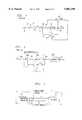
- FIG. 4An illustrative communications system embodying the principles of the invention is shown in FIG. 4.
- the communications systemcomprises data communications equipment (DCE) 11, communications channel 15, and DCE 21.
- DCEdata communications equipment
- Transmitter 10includes precoding and transmits a data signal to receiver 20, via communications channel 15, e.g., over primary channel 17.
- Receiver 20communicates an adaptation signal, in accordance with the principles of the invention, to transmitter 10 over reverse channel 16.
- primary channel 17 and reverse channel 16are shown as separate channels for simplicity, they are not so limited and represent any single, or plurality, of communications channels that enables transmission in both directions whether half-duplex, or full-duplex, over any number of different types of facilities (such as is found in the public-switched-telephone network).
- reverse channel 16can be a control channel that exists on a full-duplex primary communications link between transmitter 10 and receiver 20, thus enabling the inventive concept to also be practiced in the corresponding receiver (not shown) associated with DCE 11 and a transmitter (not shown), associated with DCE 21.
- FIG. 5is an illustrative block diagram of receiver 20 in accordance with the principles of the invention.
- receiver 20has been simplified to focus on the inventive concept, e.g., typically there is other receiver circuitry between feedforward filter 105 and communications channel 15.
- FFfeedforward filter
- Tomlinson decoder/slicer 110infinite size slicer 115
- adder 120processor 125 and transmitter 130.
- a received data signal for processingis applied to feed forward filter 105, from primary channel 17.
- Feedforward filter 105whitens the noise present in the received data signal to generate the output signal y(n).
- the latteris applied to Tomlinson decoder/slicer 110, infinite size slicer 115, and adder 120.
- Tomlinson decoder/slicerincludes circuitry that performs in a complementary fashion to the Tomlinson precoder of transmitter 10 to provide an estimate, x(n), of the actually transmitted data symbol, x(n).
- y(n)is, ideally, ISI free (a small ISI level may still be produced due to misadjustment in the pre-equalizer) and the additive noise is close to white.
- transmitter 10incorporates preceding, transmitter 10 has an ideal reference for x(n)--namely x(n) itself. Therefore, and in accordance with the inventive concept, samples of y(n) contain sufficient information for adapting the pre-equalizer of transmitter 10 and can simply be communicated back to transmitter 10 over reverse channel 16 (ignoring for the moment adder 120 and infinite size slicer 115). For example, a few bits per sample of y(n) can be transferred to transmitter 10 every K time instants.
- the convergence ratewill be slower than that of an adaptive DFE directly located in the receiver.
- This convergence ratecan be increased to a degree by either increasing the data rate on the reverse channel (typically not an attractive systems option), or, where the data rate for the reverse channel is fixed, by reducing the number of bits required for each sample of y(n).
- an error signalis developed for transmission from DCE 21 to DCE 11 such that the number of bits required for representing the error signal is less than the number of bits required for y(n).
- adder 120 of receiver 20develops an approximation (denoted by e(n)) of the error signal e(n) by using an estimation of the transmitted data, x(n), which is developed by infinite size slicer 115.
- the latteris required since a form of modulo preceding is used.
- the estimate x'(n) developed by Tomlinson decoder/slicer 110may generate a large error at the boundary of the signal point constellation due to the modulo nature of the preceding
- the received signal pointmay be on one side of the constellation but the sliced signal point is on the opposite side, which would yield a large error value. Therefore, infinite size slicer 115 is configured to mathematically represent an infinite signal point constellation.
- Processor 125processes the error signal estimate, e(n), in any one of a number of ways (some of which are described below) to generate an adaptation signal 126 for transmission back to transmitter 10 over reverse channel 16, via transmitter 130 of DCE 21.
- FIG. 6is an illustrative block diagram of a portion of DCE 11 in accordance with the principles of the invention.
- FIG. 6is similar to FIG. 2 described above except for the addition of receiver 230 and processor 225.
- the processor 225operates to generate an error signal as a function of the adaptation signal and a data signal that is not pre-coded, and then update values of the set of coefficients as a function of the error signal.
- FIG. 7shows a generalized method in accordance with the principles of the invention as described above.
- processor 125 of DCE 21generates an adaptation signal in step 305 and transfers this signal to DCE 11 via reverse channel 16 in step 310.
- processor 125 of DCE 21generates the sign of e(n) in step 405 and transfers the sign of e(n) to DCE 11 via reverse channel 16 in step 410.
- the value of the sign of e(n)is based upon one sample per data block of length K.
- Processor 225 of DCE 11recovers the sign of e(n) from reverse channel 16 in step 415 and using any well-known sign algorithm calculates the changes to the coefficient values in step 420.
- ign algorithmsare known in the art. For example, see V. J. Mathews and S. H.
- the adaptation of the pre-equalizer coefficientstakes the form:
- processor 125statistically processes e(n) to generate at least one statistical parameter in step 505 and transfers the statistical parameter(s) to DCE 11 via reverse channel 16 in step 510.
- This methodis aimed at utilizing the data available in receiver 20 for the K samples (whereas the adaptation of the sign algorithm is based on one sample per data block of length K), and avoiding the need for synchronization between e(n) and x(n-i).
- ⁇ e 2be the variance of the error e(n).
- ⁇ e 2can be evaluated by: ##EQU1##
- the adaptation of the i-th coefficientcan be performed by:
- ⁇ iis an estimation of the gradient of ⁇ e 2 .
- equation (3)yields the following estimation for the gradient: ##EQU2## It is easy to see that by using this type of averaging in step 505 (hereafter referred to as gradient estimation), the variance of the minimum error in the estimation of the gradient is reduced by a factor of K. Note, that the misadjustment is proportional to this variance. Hence, the adaptation step size can be increased for obtaining a desired misadjustment, provided that the increased step size would ensure convergence. Increasing the step size would also accelerate the convergence of the pre-equalizer. Notice that gradient estimation is mostly effective for slow varying channels, where the channel is quasi-stationary for a period of K transmitted symbols.
- a set of values of ⁇ i for each coefficientis calculated by processor 125 in step 505 and then transmitted to DCE 11 in step 510.
- Processor 225 of DCE 11recovers the statistical parameter(s), here represented by ⁇ i for each of the coefficients in step 515.
- a disadvantage of the above-described gradient estimation methodis the need to transfer through the reverse channel different information for each coefficient, whereas in the sign algorithm only one bit is required for the adaptation of all the coefficients.
- the gradient estimation methoduses more bandwidth than the above-mentioned use of a sign algorithm.
- the gradient estimation methodcan be further modified so as to reduce the bandwidth required over the reverse channel. For example, requirements of the reverse channel data rate can be reduced by transferring over the reverse channel only a few bits per coefficient for representing ⁇ i . Indeed, even one bit may be considered (due to the accuracy of the estimation which is based on an average error).
- Yet another variationis to only adapt a few dominant coefficients of the pre-equalizer in the transmitter. Recall that the aim of performing adaptation of the pre-equalizer is eliminating error propagation, mostly caused by a few ISI coefficients. The remaining coefficients can be used to adapt a DFE in the receiver during the communications phase.
- the mean square error, E ⁇ e 2 (n) ⁇is small after the initialization process.
- the mean squared errormay serve as a figure-of-merit for the adaptation step size.
- Increase in the mean squared. errormay be interpreted as an increase in the misadjustment.
- the pre-equalizercan increase the step size (using the reverse channel) for a short period in order to accelerate the adaptation.
- the adaptation signalcan take many forms and only a few illustrative suggestions were described above.
- the adaptation signalcan represent a sequence of k-bit size words, where each k-bit size word represents the location of the first non-zero bit in a corresponding value of, e.g., e(n), as opposed to the value of e(n) itself. This approach, in effect, sends the most significant, non-zero bit(s) of the signal used for adaptation.
- any precoding schemecan be used in conjunction with the inventive concept.
- the precoding specified by CCITT modulation standard V.34could also be used with correspondingly straightforward changes in the receiver structure.
- This proposed schemecan be used in either an uncoded or coded communications system.
- any one or more of those building blockscan be carried out using one or more appropriate programmed processors, e.g., the above-described pre-equalizer and processor of transmitter 10 can be implemented together in a suitably programmed digital signal processor.
Landscapes
- Engineering & Computer Science (AREA)
- Computer Networks & Wireless Communication (AREA)
- Signal Processing (AREA)
- Physics & Mathematics (AREA)
- Spectroscopy & Molecular Physics (AREA)
- Power Engineering (AREA)
- Cable Transmission Systems, Equalization Of Radio And Reduction Of Echo (AREA)
- Dc Digital Transmission (AREA)
Abstract
Description
ƒ.sub.i (n+1)=ƒ.sub.i (n)+2μe(n)x(n-i),(1)
ƒ.sub.i (n+1)=ƒ.sub.i (n)+2μ(sgn e(n)!x(n-i)),(2)
ƒ.sub.i (n)=ƒ.sub.i (n-1)-μ∇.sub.i,(4)
Claims (16)
Priority Applications (2)
| Application Number | Priority Date | Filing Date | Title |
|---|---|---|---|
| US08/605,404US5881108A (en) | 1996-02-22 | 1996-02-22 | Adaptive pre-equalizer for use in data communications equipment |
| TW086111337ATW359932B (en) | 1996-02-22 | 1997-08-07 | A transmitter apparatus for performing pre-coding, communications equipment with a precoder, communication system with such an equipment, and the method for pre-equalizing a signal in a communication device |
Applications Claiming Priority (1)
| Application Number | Priority Date | Filing Date | Title |
|---|---|---|---|
| US08/605,404US5881108A (en) | 1996-02-22 | 1996-02-22 | Adaptive pre-equalizer for use in data communications equipment |
Publications (1)
| Publication Number | Publication Date |
|---|---|
| US5881108Atrue US5881108A (en) | 1999-03-09 |
Family
ID=24423526
Family Applications (1)
| Application Number | Title | Priority Date | Filing Date |
|---|---|---|---|
| US08/605,404Expired - LifetimeUS5881108A (en) | 1996-02-22 | 1996-02-22 | Adaptive pre-equalizer for use in data communications equipment |
Country Status (2)
| Country | Link |
|---|---|
| US (1) | US5881108A (en) |
| TW (1) | TW359932B (en) |
Cited By (50)
| Publication number | Priority date | Publication date | Assignee | Title |
|---|---|---|---|---|
| US6141783A (en)* | 1998-04-10 | 2000-10-31 | International Business Machines Corporation | Error propagation limiting encoder/decoder for multilevel decision feedback equalization |
| US6185250B1 (en) | 1999-03-10 | 2001-02-06 | Lucent Technologies Inc. | Training of level learning modems |
| US6243425B1 (en)* | 1997-07-22 | 2001-06-05 | Globespan Technologies, Inc. | Adaptive precoding system and method for equalizing communication signal |
| WO2001050645A1 (en)* | 1999-12-30 | 2001-07-12 | Tioga Technologies Inc. | Data transceiver with filtering and precoding |
| EP1124359A2 (en) | 2000-02-10 | 2001-08-16 | Texas Instruments Incorporated | Laroia-Tretter-Farvardin precoder for PCM modems |
| US6285859B1 (en)* | 1998-02-16 | 2001-09-04 | Alcatel | Method for predistortion of a signal transmitted between two units of a telecommunications network and a unit for carrying out the method |
| US6324220B1 (en)* | 1999-02-19 | 2001-11-27 | Adaptive Broadband Ltd. | Stabilized precoder for data transmission |
| US20010055343A1 (en)* | 2000-04-06 | 2001-12-27 | Lee-Fang Wei | Upstream data transmission |
| US20020012152A1 (en)* | 2000-07-21 | 2002-01-31 | Broadcom Corporation | Methods and systems for digitally processing optical data signals |
| US20020034222A1 (en)* | 2000-04-28 | 2002-03-21 | Aaron Buchwald | Methods and systems for adaptive receiver equalization |
| US20020080898A1 (en)* | 2000-07-21 | 2002-06-27 | Broadcom Incorporated | Methods and systems for DSP-based receivers |
| EP1225738A1 (en)* | 2001-01-23 | 2002-07-24 | Sagem S.A. | Adaptive bidirectional modem with filtering means common to the emission and the reception blocks and arranged to operate alternately |
| US20020159537A1 (en)* | 2001-04-27 | 2002-10-31 | Crilly William J. | Multipath communication methods and apparatuses |
| US20030031269A1 (en)* | 2000-07-24 | 2003-02-13 | S.T. Microelectronics | Semi-stationary quiescent mode transmission |
| US20030035495A1 (en)* | 2000-01-18 | 2003-02-20 | Heikki Laamanen | Method and apparatus for implementing a channel correction in a digital data link |
| US6532267B1 (en)* | 1999-05-21 | 2003-03-11 | Alantro Communications, Inc. | Variable rate constellation precoding |
| WO2002093855A3 (en)* | 2001-05-11 | 2003-04-03 | Infineon Technologies Ag | Method and system for transferring data with tomlinson-coding |
| US6570917B1 (en) | 1999-03-10 | 2003-05-27 | Agere Systems Inc. | Equalizer training in the presence of network impairment |
| EP1256183A4 (en)* | 2000-02-03 | 2003-07-02 | Motorola Inc | Data mode signaling system for pcm modem adaptation |
| US6597745B1 (en)* | 1999-04-06 | 2003-07-22 | Eric M. Dowling | Reduced complexity multicarrier precoder |
| US6600780B1 (en) | 1999-03-10 | 2003-07-29 | Agere Systems Inc. | Apparatus and method for adapting a filter of an analog modem |
| US20030185192A1 (en)* | 2002-03-28 | 2003-10-02 | Interdigital Technology Corporation | Transmit processing using receiver functions |
| US6650698B1 (en)* | 1999-09-29 | 2003-11-18 | Conexant Systems, Inc. | Non-linear equalization for the upstream data connection of 56K PCM modems |
| US6680978B1 (en)* | 1999-03-01 | 2004-01-20 | Adtran, Inc. | Method and apparatus for nonlinear filtering and controlling the peak-to-average ratio |
| US20040095517A1 (en)* | 1999-01-08 | 2004-05-20 | Dai Nippon Printing Co., Ltd. | Information recording medium |
| US6798851B1 (en)* | 1999-12-09 | 2004-09-28 | Agere Systems Inc. | Decoding for a non-linear codec |
| US20040252755A1 (en)* | 1999-08-13 | 2004-12-16 | Broadcom Corporation | Decision feedback equalizer and precoder ramping circuit |
| WO2005032084A1 (en)* | 2003-09-26 | 2005-04-07 | Elonics Limited | Adaptive equalisation for communication systems at transmitter with feedback from receiver |
| US6879639B1 (en) | 1999-12-30 | 2005-04-12 | Tioga Technologies Inc. | Data transceiver with filtering and precoding |
| US6928107B1 (en)* | 1999-09-27 | 2005-08-09 | Mindspeed Technologies, Inc. | Iterative precoding system and method for resource limited data transceivers |
| US20050281343A1 (en)* | 2004-06-16 | 2005-12-22 | International Business Machines Corporation | Automatic adaptive equalization method and system for high-speed serial transmission link |
| US20060067440A1 (en)* | 2004-09-30 | 2006-03-30 | International Business Machines Corporation | High Speed Multi-Mode Receiver |
| US7113539B1 (en)* | 1996-06-07 | 2006-09-26 | Sarnoff Corporation | Method and apparatus for performing bandedge equalization |
| US20060251194A1 (en)* | 2005-05-03 | 2006-11-09 | Intel Corporation | Techniques for reduction of delayed reflection inter-symbol interference |
| US7142595B1 (en)* | 2001-04-12 | 2006-11-28 | Conexant, Inc. | System and method for decreasing cross-talk effects in time-domain-modulation (TDM) digital subscriber line (DSL) systems |
| US7155165B1 (en)* | 1998-10-30 | 2006-12-26 | Robert Bosch Gmbh | Method and radio station for the transmission of predistored signals via several radio channels |
| US7173979B1 (en)* | 1998-08-18 | 2007-02-06 | Fraunhofer-Gesellschaft Zur Foerderung Der Angewandten Forschung E.V. | Method and device for transmitting information symbols using a plurality of carriers and method and device for receiving information symbols |
| US7200180B2 (en) | 1999-12-30 | 2007-04-03 | Tioga Technologies, Inc. | Data transceiver with filtering and precoding |
| US20080049867A1 (en)* | 1999-12-09 | 2008-02-28 | Agere Systems Inc. | Precoding for a non-linear codec |
| US7471225B1 (en)* | 2006-02-27 | 2008-12-30 | Marvell International Ltd. | Transmitter digital-to-analog converter with noise shaping |
| US20090024367A1 (en)* | 2007-07-17 | 2009-01-22 | Caterpillar Inc. | Probabilistic modeling system for product design |
| US20140241409A1 (en)* | 2010-02-05 | 2014-08-28 | Comcast Cable Communications, Llc | Modulation analysis and distortion identification |
| US8923433B2 (en) | 1997-06-20 | 2014-12-30 | Massachusetts Institute Of Technology | Digital transmitter |
| US8971394B2 (en) | 2010-02-05 | 2015-03-03 | Comcast Cable Communications, Llc | Inducing response signatures in a communication network |
| US8994398B2 (en) | 2003-12-17 | 2015-03-31 | Rambus Inc. | High speed signaling system with adaptive transmit pre-emphasis |
| US9015786B2 (en) | 2012-12-03 | 2015-04-21 | Comcast Cable Communications, Llc | Noise ingress detection |
| US9356743B2 (en) | 2001-02-02 | 2016-05-31 | Rambus Inc. | Method and apparatus for evaluating and optimizing a signaling system |
| US9380475B2 (en) | 2013-03-05 | 2016-06-28 | Comcast Cable Communications, Llc | Network implementation of spectrum analysis |
| US9444719B2 (en) | 2013-03-05 | 2016-09-13 | Comcast Cable Communications, Llc | Remote detection and measurement of data signal leakage |
| US9819520B1 (en)* | 2016-12-15 | 2017-11-14 | Cadence Design Systems, Inc. | Method of adaptively controlling the pre-cursor coefficient in a transmit equalizer |
Families Citing this family (1)
| Publication number | Priority date | Publication date | Assignee | Title |
|---|---|---|---|---|
| TWI383599B (en)* | 2008-06-02 | 2013-01-21 | Univ Nat Taiwan | Duobinary transceiver |
Citations (8)
| Publication number | Priority date | Publication date | Assignee | Title |
|---|---|---|---|---|
| US4577329A (en)* | 1982-10-11 | 1986-03-18 | Telecommunications Radioelectriques Et Telephoniques T.R.T. | Self-adaptive equalizer for baseband data signals |
| US4866736A (en)* | 1987-06-09 | 1989-09-12 | U.S. Philips Corporation | Data transmission system comprising a decision feedback equalizer and using partial-response techniques |
| US5008903A (en)* | 1989-05-25 | 1991-04-16 | A.T. & T. Paradyne | Adaptive transmit pre-emphasis for digital modem computed from noise spectrum |
| US5251328A (en)* | 1990-12-20 | 1993-10-05 | At&T Bell Laboratories | Predistortion technique for communications systems |
| US5263051A (en)* | 1991-07-05 | 1993-11-16 | Codex Corporation | Device and method of interleaving for a trellis precoding system |
| US5291520A (en)* | 1991-02-06 | 1994-03-01 | General Datacomm, Inc. | Methods and apparatus employing distribution preserving Tomlinson precoding in transmission of digital data signals |
| US5513216A (en)* | 1994-10-13 | 1996-04-30 | At&T Corp. | Hybrid equalizer arrangement for use in data communications equipment |
| US5646957A (en)* | 1995-07-28 | 1997-07-08 | Lucent Technologies Inc. | Burst update for an adaptive equalizer |
- 1996
- 1996-02-22USUS08/605,404patent/US5881108A/ennot_activeExpired - Lifetime
- 1997
- 1997-08-07TWTW086111337Apatent/TW359932B/ennot_activeIP Right Cessation
Patent Citations (8)
| Publication number | Priority date | Publication date | Assignee | Title |
|---|---|---|---|---|
| US4577329A (en)* | 1982-10-11 | 1986-03-18 | Telecommunications Radioelectriques Et Telephoniques T.R.T. | Self-adaptive equalizer for baseband data signals |
| US4866736A (en)* | 1987-06-09 | 1989-09-12 | U.S. Philips Corporation | Data transmission system comprising a decision feedback equalizer and using partial-response techniques |
| US5008903A (en)* | 1989-05-25 | 1991-04-16 | A.T. & T. Paradyne | Adaptive transmit pre-emphasis for digital modem computed from noise spectrum |
| US5251328A (en)* | 1990-12-20 | 1993-10-05 | At&T Bell Laboratories | Predistortion technique for communications systems |
| US5291520A (en)* | 1991-02-06 | 1994-03-01 | General Datacomm, Inc. | Methods and apparatus employing distribution preserving Tomlinson precoding in transmission of digital data signals |
| US5263051A (en)* | 1991-07-05 | 1993-11-16 | Codex Corporation | Device and method of interleaving for a trellis precoding system |
| US5513216A (en)* | 1994-10-13 | 1996-04-30 | At&T Corp. | Hybrid equalizer arrangement for use in data communications equipment |
| US5646957A (en)* | 1995-07-28 | 1997-07-08 | Lucent Technologies Inc. | Burst update for an adaptive equalizer |
Non-Patent Citations (4)
| Title |
|---|
| United States Patent Application by Jin Der Wang, entitled A Hybrid Equalizer Arrangement for Use in Data Communications Equipment , Serial No. 08/322878, filed on Oct. 13, 1994.* |
| United States Patent Application by Jin-Der Wang, entitled "A Hybrid Equalizer Arrangement for Use in Data Communications Equipment", Serial No. 08/322878, filed on Oct. 13, 1994. |
| United States Patent Application by S. Gadot et al., entitled "A Hybrid Equalizer Arrangement for Use in Data Communications Equipment", Serial No. )8/322877, filed on Oct. 13, 1994. |
| United States Patent Application by S. Gadot et al., entitled A Hybrid Equalizer Arrangement for Use in Data Communications Equipment , Serial No. )8/322877, filed on Oct. 13, 1994.* |
Cited By (125)
| Publication number | Priority date | Publication date | Assignee | Title |
|---|---|---|---|---|
| US7113539B1 (en)* | 1996-06-07 | 2006-09-26 | Sarnoff Corporation | Method and apparatus for performing bandedge equalization |
| US9647857B2 (en) | 1997-06-20 | 2017-05-09 | Massachusetts Institute Of Technology | Digital transmitter |
| US8923433B2 (en) | 1997-06-20 | 2014-12-30 | Massachusetts Institute Of Technology | Digital transmitter |
| US8989303B2 (en) | 1997-06-20 | 2015-03-24 | Massachusetts Institute Of Technology | Digital transmitter |
| US9419824B2 (en) | 1997-06-20 | 2016-08-16 | Massachusetts Institute Of Technology | Digital transmitter |
| US6243425B1 (en)* | 1997-07-22 | 2001-06-05 | Globespan Technologies, Inc. | Adaptive precoding system and method for equalizing communication signal |
| US6285859B1 (en)* | 1998-02-16 | 2001-09-04 | Alcatel | Method for predistortion of a signal transmitted between two units of a telecommunications network and a unit for carrying out the method |
| US6141783A (en)* | 1998-04-10 | 2000-10-31 | International Business Machines Corporation | Error propagation limiting encoder/decoder for multilevel decision feedback equalization |
| US7173979B1 (en)* | 1998-08-18 | 2007-02-06 | Fraunhofer-Gesellschaft Zur Foerderung Der Angewandten Forschung E.V. | Method and device for transmitting information symbols using a plurality of carriers and method and device for receiving information symbols |
| US7155165B1 (en)* | 1998-10-30 | 2006-12-26 | Robert Bosch Gmbh | Method and radio station for the transmission of predistored signals via several radio channels |
| US20040095517A1 (en)* | 1999-01-08 | 2004-05-20 | Dai Nippon Printing Co., Ltd. | Information recording medium |
| US6324220B1 (en)* | 1999-02-19 | 2001-11-27 | Adaptive Broadband Ltd. | Stabilized precoder for data transmission |
| US6680978B1 (en)* | 1999-03-01 | 2004-01-20 | Adtran, Inc. | Method and apparatus for nonlinear filtering and controlling the peak-to-average ratio |
| US6570917B1 (en) | 1999-03-10 | 2003-05-27 | Agere Systems Inc. | Equalizer training in the presence of network impairment |
| US6185250B1 (en) | 1999-03-10 | 2001-02-06 | Lucent Technologies Inc. | Training of level learning modems |
| US6600780B1 (en) | 1999-03-10 | 2003-07-29 | Agere Systems Inc. | Apparatus and method for adapting a filter of an analog modem |
| US20060140298A1 (en)* | 1999-04-06 | 2006-06-29 | Dowling Eric M | Reduced complexity multicarrier precoder |
| US20090116576A1 (en)* | 1999-04-06 | 2009-05-07 | Rpx-Nw Acquisition Llc | Reduced complexity multicarrier precoder |
| US7519132B2 (en) | 1999-04-06 | 2009-04-14 | Rpx-Nw Acquisition Llc | Reduced complexity multicarrier precoder |
| US8175188B2 (en) | 1999-04-06 | 2012-05-08 | Rpx Corporation | Reduced complexity multicarrier precoder |
| US6597745B1 (en)* | 1999-04-06 | 2003-07-22 | Eric M. Dowling | Reduced complexity multicarrier precoder |
| US7046740B2 (en) | 1999-04-06 | 2006-05-16 | Eric Morgan Dowling | Reduced complexity multicarrier precoder |
| US6532267B1 (en)* | 1999-05-21 | 2003-03-11 | Alantro Communications, Inc. | Variable rate constellation precoding |
| US20040252755A1 (en)* | 1999-08-13 | 2004-12-16 | Broadcom Corporation | Decision feedback equalizer and precoder ramping circuit |
| US7489725B2 (en)* | 1999-08-13 | 2009-02-10 | Broadcom Corporation | Decision feedback equalizer and precoder ramping circuit |
| US6928107B1 (en)* | 1999-09-27 | 2005-08-09 | Mindspeed Technologies, Inc. | Iterative precoding system and method for resource limited data transceivers |
| US6650698B1 (en)* | 1999-09-29 | 2003-11-18 | Conexant Systems, Inc. | Non-linear equalization for the upstream data connection of 56K PCM modems |
| US6798851B1 (en)* | 1999-12-09 | 2004-09-28 | Agere Systems Inc. | Decoding for a non-linear codec |
| US20080049867A1 (en)* | 1999-12-09 | 2008-02-28 | Agere Systems Inc. | Precoding for a non-linear codec |
| US7593479B2 (en) | 1999-12-09 | 2009-09-22 | Agere Systems Inc. | Precoding for a non-linear codec |
| US6879639B1 (en) | 1999-12-30 | 2005-04-12 | Tioga Technologies Inc. | Data transceiver with filtering and precoding |
| US7200180B2 (en) | 1999-12-30 | 2007-04-03 | Tioga Technologies, Inc. | Data transceiver with filtering and precoding |
| US6411657B1 (en) | 1999-12-30 | 2002-06-25 | Tioga Technologies Inc. | DSL transmitter with digital filtering using a Tomlinson-Harashima precoder |
| WO2001050645A1 (en)* | 1999-12-30 | 2001-07-12 | Tioga Technologies Inc. | Data transceiver with filtering and precoding |
| US7512191B2 (en)* | 2000-01-18 | 2009-03-31 | Tellabs Oy | Method and apparatus for implementing a channel correction in a digital data link |
| US20030035495A1 (en)* | 2000-01-18 | 2003-02-20 | Heikki Laamanen | Method and apparatus for implementing a channel correction in a digital data link |
| JP5010084B2 (en)* | 2000-02-03 | 2012-08-29 | ゼネラル・エレクトリック・キャピタル・コーポレーション | Data mode signaling for PCM modem adaptation |
| JP2003522459A (en)* | 2000-02-03 | 2003-07-22 | モトローラ・インコーポレイテッド | Data mode signaling for PCM modem adaptation |
| EP1256183A4 (en)* | 2000-02-03 | 2003-07-02 | Motorola Inc | Data mode signaling system for pcm modem adaptation |
| US6434190B1 (en) | 2000-02-10 | 2002-08-13 | Texas Instruments Incorporated | Generalized precoder for the upstream voiceband modem channel |
| EP1124359A2 (en) | 2000-02-10 | 2001-08-16 | Texas Instruments Incorporated | Laroia-Tretter-Farvardin precoder for PCM modems |
| US7245675B2 (en) | 2000-04-06 | 2007-07-17 | Lucent Technologies Inc. | Upstream data transmission |
| US7272174B2 (en) | 2000-04-06 | 2007-09-18 | Lucent Technologies Inc. | Upstream data transmission |
| US20010055343A1 (en)* | 2000-04-06 | 2001-12-27 | Lee-Fang Wei | Upstream data transmission |
| US6931072B2 (en) | 2000-04-06 | 2005-08-16 | Lucent Technologies Inc. | Upstream data transmission |
| US20050213671A1 (en)* | 2000-04-06 | 2005-09-29 | Lee-Fang Wei | Upstream data transmission |
| US7286597B2 (en) | 2000-04-28 | 2007-10-23 | Broadcom Corporation | Methods and systems for adaptive receiver equalization |
| US8798219B2 (en) | 2000-04-28 | 2014-08-05 | Broadcom Corporation | High-speed serial data transceiver and related methods |
| US6509773B2 (en) | 2000-04-28 | 2003-01-21 | Broadcom Corporation | Phase interpolator device and method |
| US7012983B2 (en) | 2000-04-28 | 2006-03-14 | Broadcom Corporation | Timing recovery and phase tracking system and method |
| US7058150B2 (en) | 2000-04-28 | 2006-06-06 | Broadcom Corporation | High-speed serial data transceiver and related methods |
| US6995594B2 (en) | 2000-04-28 | 2006-02-07 | Broadcom Corporation | Phase interpolator device and method |
| US20020034222A1 (en)* | 2000-04-28 | 2002-03-21 | Aaron Buchwald | Methods and systems for adaptive receiver equalization |
| US7016449B2 (en) | 2000-04-28 | 2006-03-21 | Broadcom Corporation | Timing recovery and frequency tracking system and method |
| US20020039395A1 (en)* | 2000-04-28 | 2002-04-04 | Buchwald Aaron W. | Timing recovery and frequency tracking system and method |
| US8223828B2 (en) | 2000-04-28 | 2012-07-17 | Broadcom Corporation | Methods and systems for adaptive receiver equalization |
| US20020044618A1 (en)* | 2000-04-28 | 2002-04-18 | Buchwald Aaron W. | High-speed serial data transceiver and related methods |
| US8824538B2 (en) | 2000-04-28 | 2014-09-02 | Broadcom Corporation | Methods and systems for adaptive receiver equalization |
| US20040212416A1 (en)* | 2000-04-28 | 2004-10-28 | Broadcom Corporation | Phase interpolator device and method |
| US6791388B2 (en) | 2000-04-28 | 2004-09-14 | Broadcom Corporation | Phase interpolator device and method |
| WO2001084724A3 (en)* | 2000-04-28 | 2002-05-23 | Broadcom Corp | Methods and systems for adaptive receiver equalization |
| US20080117963A1 (en)* | 2000-04-28 | 2008-05-22 | Broadcom Corporation | Methods and systems for adaptive receiver equalization |
| US8472512B2 (en) | 2000-04-28 | 2013-06-25 | Broadcom Corporation | Methods and systems for adaptive receiver equalization |
| US8433020B2 (en) | 2000-04-28 | 2013-04-30 | Broadcom Corporation | High-speed serial data transceiver and related methods |
| US7564866B2 (en) | 2000-07-21 | 2009-07-21 | Broadcom Corporation | Methods and systems for digitally processing optical data signals |
| US20090310665A1 (en)* | 2000-07-21 | 2009-12-17 | Broadcom Corporation | Methods and Systems for Digitally Processing Optical Data Signals |
| US7245638B2 (en) | 2000-07-21 | 2007-07-17 | Broadcom Corporation | Methods and systems for DSP-based receivers |
| US7778286B2 (en) | 2000-07-21 | 2010-08-17 | Broadcom Corporation | Methods and systems for DSP-based receivers |
| US20020080898A1 (en)* | 2000-07-21 | 2002-06-27 | Broadcom Incorporated | Methods and systems for DSP-based receivers |
| US20100310024A1 (en)* | 2000-07-21 | 2010-12-09 | Broadcom Corporation | Methods and systems for DSP-based receivers |
| US8363683B2 (en) | 2000-07-21 | 2013-01-29 | Broadcom Corporation | Methods and systems for DSP-based receivers |
| US20020012152A1 (en)* | 2000-07-21 | 2002-01-31 | Broadcom Corporation | Methods and systems for digitally processing optical data signals |
| US7835387B2 (en) | 2000-07-21 | 2010-11-16 | Broadcom Corporation | Methods and systems for digitally processing data signals |
| US20030031269A1 (en)* | 2000-07-24 | 2003-02-13 | S.T. Microelectronics | Semi-stationary quiescent mode transmission |
| US6885699B2 (en) | 2000-07-24 | 2005-04-26 | Stmicroelectronics Ltd. | Semi-stationary quiescent mode transmission |
| FR2819970A1 (en)* | 2001-01-23 | 2002-07-26 | Sagem | METHOD FOR SETTING UP AND USING A BIDIRECTIONAL DATA LINK AND MODEM FOR IMPLEMENTING THE METHOD |
| EP1225738A1 (en)* | 2001-01-23 | 2002-07-24 | Sagem S.A. | Adaptive bidirectional modem with filtering means common to the emission and the reception blocks and arranged to operate alternately |
| US9356743B2 (en) | 2001-02-02 | 2016-05-31 | Rambus Inc. | Method and apparatus for evaluating and optimizing a signaling system |
| US10855413B2 (en) | 2001-02-02 | 2020-12-01 | Rambus Inc. | Method and apparatus for evaluating and optimizing a signaling system |
| US7142595B1 (en)* | 2001-04-12 | 2006-11-28 | Conexant, Inc. | System and method for decreasing cross-talk effects in time-domain-modulation (TDM) digital subscriber line (DSL) systems |
| US20020159537A1 (en)* | 2001-04-27 | 2002-10-31 | Crilly William J. | Multipath communication methods and apparatuses |
| US7177369B2 (en)* | 2001-04-27 | 2007-02-13 | Vivato, Inc. | Multipath communication methods and apparatuses |
| WO2002093855A3 (en)* | 2001-05-11 | 2003-04-03 | Infineon Technologies Ag | Method and system for transferring data with tomlinson-coding |
| US20040170225A1 (en)* | 2001-05-11 | 2004-09-02 | Stefan Krause | Method and system for transferring data |
| US20090323775A1 (en)* | 2002-03-28 | 2009-12-31 | Interdigital Technology Corporation | Transmit processing using receiver functions |
| US7593357B2 (en) | 2002-03-28 | 2009-09-22 | Interdigital Technology Corporation | Transmit processing using receiver functions |
| US8531938B2 (en) | 2002-03-28 | 2013-09-10 | Interdigital Technology Corporation | Transmit processing using receiver functions |
| US20030185192A1 (en)* | 2002-03-28 | 2003-10-02 | Interdigital Technology Corporation | Transmit processing using receiver functions |
| WO2005032084A1 (en)* | 2003-09-26 | 2005-04-07 | Elonics Limited | Adaptive equalisation for communication systems at transmitter with feedback from receiver |
| US9000803B2 (en) | 2003-12-17 | 2015-04-07 | Rambus Inc. | High speed signaling system with adaptive transmit pre-emphasis |
| US10411923B2 (en)* | 2003-12-17 | 2019-09-10 | Rambus Inc. | High speed signaling system with adaptive transmit pre-emphasis |
| US9287909B2 (en) | 2003-12-17 | 2016-03-15 | Rambus Inc. | High speed signaling system with adaptive transmit pre-emphasis |
| US8994398B2 (en) | 2003-12-17 | 2015-03-31 | Rambus Inc. | High speed signaling system with adaptive transmit pre-emphasis |
| US9705710B2 (en) | 2003-12-17 | 2017-07-11 | Rambus Inc. | High speed signaling system with adaptive transmit pre-emphasis |
| US11706061B2 (en) | 2003-12-17 | 2023-07-18 | Rambus Inc. | High speed signaling system with adaptive transmit pre-emphasis |
| US20170338981A1 (en)* | 2003-12-17 | 2017-11-23 | Rambus Inc. | High speed signaling system with adaptive transmit pre-emphasis |
| US10771295B2 (en) | 2003-12-17 | 2020-09-08 | Rambus Inc. | High speed signaling system with adaptive transmit pre-emphasis |
| US11233678B2 (en) | 2003-12-17 | 2022-01-25 | Rambus Inc. | High speed signaling system with adaptive transmit pre-emphasis |
| US7295618B2 (en) | 2004-06-16 | 2007-11-13 | International Business Machines Corporation | Automatic adaptive equalization method and system for high-speed serial transmission link |
| US20050281343A1 (en)* | 2004-06-16 | 2005-12-22 | International Business Machines Corporation | Automatic adaptive equalization method and system for high-speed serial transmission link |
| US20080298520A1 (en)* | 2004-09-30 | 2008-12-04 | International Business Machines Corporation | High-speed multi-mode receiver |
| US20060067440A1 (en)* | 2004-09-30 | 2006-03-30 | International Business Machines Corporation | High Speed Multi-Mode Receiver |
| US7660350B2 (en) | 2004-09-30 | 2010-02-09 | International Business Machines Corporation | High-speed multi-mode receiver |
| US7409019B2 (en)* | 2004-09-30 | 2008-08-05 | International Business Machines Corporation | High Speed Multi-Mode Receiver with adaptive receiver equalization and controllable transmitter pre-distortion |
| US7724847B2 (en)* | 2005-05-03 | 2010-05-25 | Intel Corporation | Techniques for reduction of delayed reflection inter-symbol interference |
| US20060251194A1 (en)* | 2005-05-03 | 2006-11-09 | Intel Corporation | Techniques for reduction of delayed reflection inter-symbol interference |
| US7773017B1 (en) | 2006-02-27 | 2010-08-10 | Marvell International Ltd. | Transmitter digital-to-analog converter with noise shaping |
| US7999711B1 (en) | 2006-02-27 | 2011-08-16 | Marvell International Ltd. | Transmitter digital-to-analog converter with noise shaping |
| US7471225B1 (en)* | 2006-02-27 | 2008-12-30 | Marvell International Ltd. | Transmitter digital-to-analog converter with noise shaping |
| US20090024367A1 (en)* | 2007-07-17 | 2009-01-22 | Caterpillar Inc. | Probabilistic modeling system for product design |
| US9438605B2 (en) | 2010-02-05 | 2016-09-06 | Comcast Cable Communications, Llc | Determining response signature commonalities |
| US9537680B2 (en) | 2010-02-05 | 2017-01-03 | Comcast Cable Communications, Llc | Inducing response signatures in a communication network |
| US20140241409A1 (en)* | 2010-02-05 | 2014-08-28 | Comcast Cable Communications, Llc | Modulation analysis and distortion identification |
| US8971394B2 (en) | 2010-02-05 | 2015-03-03 | Comcast Cable Communications, Llc | Inducing response signatures in a communication network |
| US9479515B2 (en) | 2010-02-05 | 2016-10-25 | Comcast Cable Communications, Llc | Identification of a fault |
| US10187397B2 (en) | 2010-02-05 | 2019-01-22 | Comcast Cable Communications, Llc | Modulation analysis and distortion identification |
| US9602518B2 (en)* | 2010-02-05 | 2017-03-21 | Comcast Cable Communications, Llc | Modulation analysis and distortion identification |
| US9015786B2 (en) | 2012-12-03 | 2015-04-21 | Comcast Cable Communications, Llc | Noise ingress detection |
| US9444719B2 (en) | 2013-03-05 | 2016-09-13 | Comcast Cable Communications, Llc | Remote detection and measurement of data signal leakage |
| US9380475B2 (en) | 2013-03-05 | 2016-06-28 | Comcast Cable Communications, Llc | Network implementation of spectrum analysis |
| US10798597B2 (en) | 2013-03-05 | 2020-10-06 | Comcast Cable Communications, Llc | Network implementation of spectrum analysis |
| US10477422B2 (en) | 2013-03-05 | 2019-11-12 | Comcast Cable Communications, Llc | Network implementation of spectrum analysis |
| US9826424B2 (en) | 2013-03-05 | 2017-11-21 | Comcast Cable Communications, Llc | Network implementation of spectrum analysis |
| US12096260B2 (en) | 2013-03-05 | 2024-09-17 | Tivo Corporation | Network implementation of spectrum analysis |
| US9819520B1 (en)* | 2016-12-15 | 2017-11-14 | Cadence Design Systems, Inc. | Method of adaptively controlling the pre-cursor coefficient in a transmit equalizer |
Also Published As
| Publication number | Publication date |
|---|---|
| TW359932B (en) | 1999-06-01 |
Similar Documents
| Publication | Publication Date | Title |
|---|---|---|
| US5881108A (en) | Adaptive pre-equalizer for use in data communications equipment | |
| US5604769A (en) | Hybrid equalizer arrangement for use in data communications equipment | |
| US5513216A (en) | Hybrid equalizer arrangement for use in data communications equipment | |
| US6151358A (en) | Method and apparatus, and computer program for producing filter coefficients for equalizers | |
| EP1540820B1 (en) | Method and apparatus for channel equalization | |
| US6069917A (en) | Blind training of a decision feedback equalizer | |
| Yang et al. | The multimodulus blind equalization algorithm | |
| US6243425B1 (en) | Adaptive precoding system and method for equalizing communication signal | |
| US7460594B2 (en) | Fast computation of linear equalizer coefficients from channel estimate | |
| US6314135B1 (en) | Method and apparatus for updating precoder coefficients in a data communication transmitter | |
| US5471504A (en) | Bilinear decision feedback equalizer | |
| KR100259317B1 (en) | Method and apparatus for improving blind convergence of two-filter adaptive equalizer | |
| EP0965207A2 (en) | Adaptation of pre-equialisers | |
| WO1998037671A1 (en) | An adaptive pre-equalizer for use in data communications equipment | |
| US5793807A (en) | Multimodulus blind eqalization using piecewise linear contours | |
| US6928107B1 (en) | Iterative precoding system and method for resource limited data transceivers | |
| US6721279B1 (en) | Method and apparatus for adaptive PCM level estimation and constellation training | |
| US6519282B1 (en) | Method for digital transmission of information | |
| Gomes et al. | Acoustic channel equalization results for the ASIMOV high-speed coherent data link | |
| KR100265058B1 (en) | Method and device for equalizing bling in digital communication system | |
| Cherubini | Nonlinear self-training adaptive equalization for partial-response systems | |
| Glavin et al. | Equalization of digital subscriber lines under dynamic channel conditions |
Legal Events
| Date | Code | Title | Description |
|---|---|---|---|
| AS | Assignment | Owner name:GLOBESPAN TECHNOLOGIES, INC. (FORMERLY KNOWN AS CA Free format text:ASSIGNMENT OF ASSIGNORS INTEREST;ASSIGNOR:LUCENT TECHNOLOGIES, INC.;REEL/FRAME:008173/0817 Effective date:19960731 | |
| AS | Assignment | Owner name:LUCENT TECHNOLOGIES INC., NEW JERSEY Free format text:ASSIGNMENT OF ASSIGNORS INTEREST;ASSIGNOR:AT&T CORP.;REEL/FRAME:008178/0161 Effective date:19960329 | |
| AS | Assignment | Owner name:BANKAMERICA BUSINESS CREDIT, INC., CALIFORNIA Free format text:SECURITY AGREEMENT;ASSIGNOR:GLOBESPAN SEMICONDUCTOR INC.;REEL/FRAME:009257/0806 Effective date:19980514 | |
| STCF | Information on status: patent grant | Free format text:PATENTED CASE | |
| FPAY | Fee payment | Year of fee payment:4 | |
| FPAY | Fee payment | Year of fee payment:8 | |
| AS | Assignment | Owner name:CONEXANT, INC.,NEW JERSEY Free format text:CHANGE OF NAME;ASSIGNOR:GLOBESPANVIRATA, INC.;REEL/FRAME:018471/0286 Effective date:20040528 Owner name:GLOBESPAN, INC., NEW JERSEY Free format text:CHANGE OF NAME;ASSIGNOR:GLOBESPAN SEMICONDUCTOR INC.;REEL/FRAME:018471/0138 Effective date:19990504 Owner name:CONEXANT, INC., NEW JERSEY Free format text:CHANGE OF NAME;ASSIGNOR:GLOBESPANVIRATA, INC.;REEL/FRAME:018471/0286 Effective date:20040528 Owner name:GLOBESPAN SEMICONDUCTOR INC., NEW JERSEY Free format text:CHANGE OF NAME;ASSIGNOR:GLOBESPAN TECHNOLOGIES INC.;REEL/FRAME:018471/0124 Effective date:19971121 Owner name:GLOBESPANVIRATA, INC., NEW JERSEY Free format text:CHANGE OF NAME;ASSIGNOR:GLOBESPAN, INC.;REEL/FRAME:018471/0253 Effective date:20011214 | |
| AS | Assignment | Owner name:BANK OF NEW YORK TRUST COMPANY, N.A., THE,ILLINOIS Free format text:SECURITY AGREEMENT;ASSIGNOR:BROOKTREE BROADBAND HOLDING, INC.;REEL/FRAME:018573/0337 Effective date:20061113 Owner name:BANK OF NEW YORK TRUST COMPANY, N.A., THE, ILLINOI Free format text:SECURITY AGREEMENT;ASSIGNOR:BROOKTREE BROADBAND HOLDING, INC.;REEL/FRAME:018573/0337 Effective date:20061113 | |
| AS | Assignment | Owner name:BROOKTREE BROADBAND HOLDING, INC.,CALIFORNIA Free format text:ASSIGNMENT OF ASSIGNORS INTEREST;ASSIGNOR:GLOBESPANVIRATA, INC.;REEL/FRAME:018826/0939 Effective date:20040228 Owner name:BROOKTREE BROADBAND HOLDING, INC., CALIFORNIA Free format text:ASSIGNMENT OF ASSIGNORS INTEREST;ASSIGNOR:GLOBESPANVIRATA, INC.;REEL/FRAME:018826/0939 Effective date:20040228 | |
| AS | Assignment | Owner name:BROOKTREE BROADBAND HOLDING, INC.,CALIFORNIA Free format text:RELEASE BY SECURED PARTY;ASSIGNOR:THE BANK OF NEW YORK MELLON TRUST COMPANY, N.A. (FORMERLY, THE BANK OF NEW YORK TRUST COMPANY, N.A.);REEL/FRAME:023998/0971 Effective date:20100128 Owner name:BROOKTREE BROADBAND HOLDING, INC., CALIFORNIA Free format text:RELEASE BY SECURED PARTY;ASSIGNOR:THE BANK OF NEW YORK MELLON TRUST COMPANY, N.A. (FORMERLY, THE BANK OF NEW YORK TRUST COMPANY, N.A.);REEL/FRAME:023998/0971 Effective date:20100128 | |
| AS | Assignment | Owner name:THE BANK OF NEW YORK, MELLON TRUST COMPANY, N.A.,I Free format text:SECURITY AGREEMENT;ASSIGNORS:CONEXANT SYSTEMS, INC.;CONEXANT SYSTEMS WORLDWIDE, INC.;CONEXANT, INC.;AND OTHERS;REEL/FRAME:024066/0075 Effective date:20100310 Owner name:THE BANK OF NEW YORK, MELLON TRUST COMPANY, N.A., Free format text:SECURITY AGREEMENT;ASSIGNORS:CONEXANT SYSTEMS, INC.;CONEXANT SYSTEMS WORLDWIDE, INC.;CONEXANT, INC.;AND OTHERS;REEL/FRAME:024066/0075 Effective date:20100310 | |
| AS | Assignment | Owner name:CONEXANT SYSTEMS, INC. (SUCCESSOR TO GLOBESPAN SEM Free format text:RELEASE BY SECURED PARTY;ASSIGNOR:BANK OF AMERICA, N.A. (SUCCESSOR TO BANKAMERICA BUSINESS CREDIT, INC.);REEL/FRAME:024523/0455 Effective date:20100524 | |
| FPAY | Fee payment | Year of fee payment:12 | |
| AS | Assignment | Owner name:CONEXANT, INC., CALIFORNIA Free format text:RELEASE BY SECURED PARTY;ASSIGNOR:THE BANK OF NEW YORK MELLON TRUST COMPANY, N.A.;REEL/FRAME:038631/0452 Effective date:20140310 Owner name:CONEXANT SYSTEMS WORLDWIDE, INC., CALIFORNIA Free format text:RELEASE BY SECURED PARTY;ASSIGNOR:THE BANK OF NEW YORK MELLON TRUST COMPANY, N.A.;REEL/FRAME:038631/0452 Effective date:20140310 Owner name:BROOKTREE BROADBAND HOLDING, INC., CALIFORNIA Free format text:RELEASE BY SECURED PARTY;ASSIGNOR:THE BANK OF NEW YORK MELLON TRUST COMPANY, N.A.;REEL/FRAME:038631/0452 Effective date:20140310 Owner name:CONEXANT SYSTEMS, INC., CALIFORNIA Free format text:RELEASE BY SECURED PARTY;ASSIGNOR:THE BANK OF NEW YORK MELLON TRUST COMPANY, N.A.;REEL/FRAME:038631/0452 Effective date:20140310 |