US5879499A - Method of manufacture of a multi-lumen catheter - Google Patents
Method of manufacture of a multi-lumen catheterDownload PDFInfo
- Publication number
- US5879499A US5879499AUS08/664,716US66471696AUS5879499AUS 5879499 AUS5879499 AUS 5879499AUS 66471696 AUS66471696 AUS 66471696AUS 5879499 AUS5879499 AUS 5879499A
- Authority
- US
- United States
- Prior art keywords
- catheter
- balloon
- lumen
- shaft
- distal
- Prior art date
- Legal status (The legal status is an assumption and is not a legal conclusion. Google has not performed a legal analysis and makes no representation as to the accuracy of the status listed.)
- Expired - Lifetime
Links
Images


Classifications
- A—HUMAN NECESSITIES
- A61—MEDICAL OR VETERINARY SCIENCE; HYGIENE
- A61M—DEVICES FOR INTRODUCING MEDIA INTO, OR ONTO, THE BODY; DEVICES FOR TRANSDUCING BODY MEDIA OR FOR TAKING MEDIA FROM THE BODY; DEVICES FOR PRODUCING OR ENDING SLEEP OR STUPOR
- A61M25/00—Catheters; Hollow probes
- A61M25/0009—Making of catheters or other medical or surgical tubes
- A61M25/0012—Making of catheters or other medical or surgical tubes with embedded structures, e.g. coils, braids, meshes, strands or radiopaque coils
- A—HUMAN NECESSITIES
- A61—MEDICAL OR VETERINARY SCIENCE; HYGIENE
- A61M—DEVICES FOR INTRODUCING MEDIA INTO, OR ONTO, THE BODY; DEVICES FOR TRANSDUCING BODY MEDIA OR FOR TAKING MEDIA FROM THE BODY; DEVICES FOR PRODUCING OR ENDING SLEEP OR STUPOR
- A61M25/00—Catheters; Hollow probes
- A61M2025/0001—Catheters; Hollow probes for pressure measurement
- A61M2025/0003—Catheters; Hollow probes for pressure measurement having an additional lumen transmitting fluid pressure to the outside for measurement
- A—HUMAN NECESSITIES
- A61—MEDICAL OR VETERINARY SCIENCE; HYGIENE
- A61M—DEVICES FOR INTRODUCING MEDIA INTO, OR ONTO, THE BODY; DEVICES FOR TRANSDUCING BODY MEDIA OR FOR TAKING MEDIA FROM THE BODY; DEVICES FOR PRODUCING OR ENDING SLEEP OR STUPOR
- A61M25/00—Catheters; Hollow probes
- A61M25/0021—Catheters; Hollow probes characterised by the form of the tubing
- A61M25/0023—Catheters; Hollow probes characterised by the form of the tubing by the form of the lumen, e.g. cross-section, variable diameter
- A61M25/0026—Multi-lumen catheters with stationary elements
- A61M25/003—Multi-lumen catheters with stationary elements characterized by features relating to least one lumen located at the distal part of the catheter, e.g. filters, plugs or valves
- A61M2025/0031—Multi-lumen catheters with stationary elements characterized by features relating to least one lumen located at the distal part of the catheter, e.g. filters, plugs or valves characterized by lumina for withdrawing or delivering, i.e. used for extracorporeal circuit treatment
- A—HUMAN NECESSITIES
- A61—MEDICAL OR VETERINARY SCIENCE; HYGIENE
- A61M—DEVICES FOR INTRODUCING MEDIA INTO, OR ONTO, THE BODY; DEVICES FOR TRANSDUCING BODY MEDIA OR FOR TAKING MEDIA FROM THE BODY; DEVICES FOR PRODUCING OR ENDING SLEEP OR STUPOR
- A61M25/00—Catheters; Hollow probes
- A61M25/0021—Catheters; Hollow probes characterised by the form of the tubing
- A61M25/0023—Catheters; Hollow probes characterised by the form of the tubing by the form of the lumen, e.g. cross-section, variable diameter
- A61M25/0026—Multi-lumen catheters with stationary elements
- A61M2025/0034—Multi-lumen catheters with stationary elements characterized by elements which are assembled, connected or fused, e.g. splittable tubes, outer sheaths creating lumina or separate cores
- A—HUMAN NECESSITIES
- A61—MEDICAL OR VETERINARY SCIENCE; HYGIENE
- A61M—DEVICES FOR INTRODUCING MEDIA INTO, OR ONTO, THE BODY; DEVICES FOR TRANSDUCING BODY MEDIA OR FOR TAKING MEDIA FROM THE BODY; DEVICES FOR PRODUCING OR ENDING SLEEP OR STUPOR
- A61M25/00—Catheters; Hollow probes
- A61M25/01—Introducing, guiding, advancing, emplacing or holding catheters
- A61M25/0105—Steering means as part of the catheter or advancing means; Markers for positioning
- A61M25/0133—Tip steering devices
- A61M25/0147—Tip steering devices with movable mechanical means, e.g. pull wires
- A61M2025/015—Details of the distal fixation of the movable mechanical means
- A—HUMAN NECESSITIES
- A61—MEDICAL OR VETERINARY SCIENCE; HYGIENE
- A61M—DEVICES FOR INTRODUCING MEDIA INTO, OR ONTO, THE BODY; DEVICES FOR TRANSDUCING BODY MEDIA OR FOR TAKING MEDIA FROM THE BODY; DEVICES FOR PRODUCING OR ENDING SLEEP OR STUPOR
- A61M25/00—Catheters; Hollow probes
- A61M25/01—Introducing, guiding, advancing, emplacing or holding catheters
- A61M25/0105—Steering means as part of the catheter or advancing means; Markers for positioning
- A61M25/0133—Tip steering devices
- A61M2025/0161—Tip steering devices wherein the distal tips have two or more deflection regions
- A—HUMAN NECESSITIES
- A61—MEDICAL OR VETERINARY SCIENCE; HYGIENE
- A61M—DEVICES FOR INTRODUCING MEDIA INTO, OR ONTO, THE BODY; DEVICES FOR TRANSDUCING BODY MEDIA OR FOR TAKING MEDIA FROM THE BODY; DEVICES FOR PRODUCING OR ENDING SLEEP OR STUPOR
- A61M25/00—Catheters; Hollow probes
- A61M25/0021—Catheters; Hollow probes characterised by the form of the tubing
- A61M25/0023—Catheters; Hollow probes characterised by the form of the tubing by the form of the lumen, e.g. cross-section, variable diameter
- A61M25/0026—Multi-lumen catheters with stationary elements
- A61M25/0032—Multi-lumen catheters with stationary elements characterized by at least one unconventionally shaped lumen, e.g. polygons, ellipsoids, wedges or shapes comprising concave and convex parts
- A—HUMAN NECESSITIES
- A61—MEDICAL OR VETERINARY SCIENCE; HYGIENE
- A61M—DEVICES FOR INTRODUCING MEDIA INTO, OR ONTO, THE BODY; DEVICES FOR TRANSDUCING BODY MEDIA OR FOR TAKING MEDIA FROM THE BODY; DEVICES FOR PRODUCING OR ENDING SLEEP OR STUPOR
- A61M25/00—Catheters; Hollow probes
- A61M25/0043—Catheters; Hollow probes characterised by structural features
- A61M25/005—Catheters; Hollow probes characterised by structural features with embedded materials for reinforcement, e.g. wires, coils, braids
- A61M25/0052—Localized reinforcement, e.g. where only a specific part of the catheter is reinforced, for rapid exchange guidewire port
- A—HUMAN NECESSITIES
- A61—MEDICAL OR VETERINARY SCIENCE; HYGIENE
- A61M—DEVICES FOR INTRODUCING MEDIA INTO, OR ONTO, THE BODY; DEVICES FOR TRANSDUCING BODY MEDIA OR FOR TAKING MEDIA FROM THE BODY; DEVICES FOR PRODUCING OR ENDING SLEEP OR STUPOR
- A61M25/00—Catheters; Hollow probes
- A61M25/0043—Catheters; Hollow probes characterised by structural features
- A61M25/005—Catheters; Hollow probes characterised by structural features with embedded materials for reinforcement, e.g. wires, coils, braids
- A61M25/0053—Catheters; Hollow probes characterised by structural features with embedded materials for reinforcement, e.g. wires, coils, braids having a variable stiffness along the longitudinal axis, e.g. by varying the pitch of the coil or braid
- A—HUMAN NECESSITIES
- A61—MEDICAL OR VETERINARY SCIENCE; HYGIENE
- A61M—DEVICES FOR INTRODUCING MEDIA INTO, OR ONTO, THE BODY; DEVICES FOR TRANSDUCING BODY MEDIA OR FOR TAKING MEDIA FROM THE BODY; DEVICES FOR PRODUCING OR ENDING SLEEP OR STUPOR
- A61M25/00—Catheters; Hollow probes
- A61M25/01—Introducing, guiding, advancing, emplacing or holding catheters
- A61M25/0105—Steering means as part of the catheter or advancing means; Markers for positioning
- A61M25/0133—Tip steering devices
- A61M25/0141—Tip steering devices having flexible regions as a result of using materials with different mechanical properties
Definitions
- the present inventionis directed to reinforced hollow tubes and their methods of manufacture and use.
- a specific application of the present inventionis for arterial return and venous drainage cannulas for a cardiopulmonary bypass system.
- the present inventionis also specifically directed to an arterial return cannula and an aortic occlusion catheter for arresting a patient's heart and placing the patient on cardiopulmonary bypass.
- Cannulas for cardiopulmonary bypass systemshave thin walls to optimize flow rates through the cannula for a given cannula size. Wall thickness is particularly important when using the system for arresting a patient's heart and placing the patient on cardiopulmonary bypass described in co-pending U.S. patent application Ser. No. 08/570,286, filed Dec. 11, 1995 by Valley et al., which is incorporated herein by reference.
- Venous bloodis withdrawn through a venous cannula and directed to an oxygenator. The oxygenated blood is then returned to the patient's arterial system through an arterial cannula.
- An aortic occlusion catheteris used to block blood flow through the ascending aorta and deliver cardioplegic fluid to arrest the heart of the patient for performing surgery on the heart and great vessels.
- the aortic occlusion catheteris inserted through a lumen in the arterial cannula which is the same lumen through which arterial blood is returned.
- An advantage of the system described aboveis that only one opening in the patient's arterial system is required for both delivery of cardioplegic fluid and return of arterial blood.
- the wall of the arterial cannulamust be minimized while retaining enough structural integrity to prevent kinking and cracking.
- the present inventionis particularly useful in providing a thin walled cannula which may be used as an arterial return cannula for the system described above.
- a known method of making a reinforced cannulais to dip a mandrel in a polymer solution and wrap a metal wire over the polymer. The mandrel is then dipped again to encase the metal wire between two layers of polymer.
- Another known method of making a reinforced cannulais to extrude a polymer tubing, wrap a metal wire around the polymer tubing, and extrude another polymer layer over the metal wire.
- a problem with the known methods of manufacturing a reinforced cannulais that the spacing between adjacent wires must be relatively large to ensure that the polymer flows between adjacent coils so that the two polymer layers bond together to form an integrated structure.
- the relatively large spacingrequires a relativley thick polymer layer to provide the necessary strength since the wire has a large pitch.
- the relatively thick polymer layeris also required to ensure that a sufficient amount of polymer is provided to fill the relatively large space.
- the resulting cannulahas a relatively thick wall.
- a specific object of the present inventionis to provide a new method of manufacturing reinforced tubing and, in particular, cannulas for venous withdrawal and arterial return of blood for a cardiopulmonary bypass system.
- an aortic occlusion catheteris passed through the arterial return cannula when practicing the invention disclosed in U.S. patent application Ser. No. 08/570,286. It is also advantageous to minimize the size of the aortic occlusion catheter for the same reasons as it is advantageous to minimize the size of the arterial return cannula.
- a limiting factor when reducing the size of the aortic occlusion catheteris that the catheter cannot kink when extending around the aortic arch.
- another object of the present inventionis to provide an aortic occlusion catheter which minimizes the catheter size while providing a catheter which resists kinking.
- the present inventionsolves the problems associated with prior art methods of making venous and arterial cannulas by providing a method which produces thin walled cannulas which retain adequate structural characteristics.
- the methodbegins with coating an elongate member, preferably with a polymer, thereby forming a coated elongate member.
- a preferred method of coating the materialis to coextrude the material over the elongate member.
- the coated elongate memberis then wound around a mandrel and heated so that the coating on adjacent parts of the wound elongate member bond together.
- the coated elongate memberis then mounted to a cannula body.
- the coated elongate memberis formed so that opposing sides of the coated elongate member engage one another when the coated elongate member is wrapped around the mandrel.
- a preferred shapeis square.
- the coatingdoes not need to flow between adjacent elongate members since the coated elongate members are configured to have sides which engage one another.
- the coated elongate memberis compressed after being wound around the mandrel.
- the coated elongate memberis preferably compressed with a heat shrink tube placed over the coated elongate member before heating.
- the shrink tubecompresses the polymer to further ensure bonding between adjacent portions of the coated elongate member.
- a further polymer layermay also be provided on the radially inner or outer wall to increase the strength of the resulting reinforced tube.
- an arterial return cannulais provided with an aortic occlusion catheter slidably coupled thereto.
- the catheterhas an occluding member movable between collapsed and expanded shapes. The expanded shape is sized and configured to occlude a patient's ascending aorta.
- the aortic occlusion catheterhas a lumen fluidly coupled to an outlet positioned distal to the occluding member for delivering cardioplegic fluid to a patient's ascending aorta.
- the arterial return cannulahas first and second sections. The first section has a first lumen and the second section has second and third lumens fluidly coupled to the first lumen. The catheter extends through the second lumen and into the first lumen. The third lumen is coupled to a source of oxygenated blood from a cardiopulmonary bypass system.
- the first sectionis rotatable with respect to the second section so that tubing and the like which is coupled to the cannula and catheter can be positioned to prevent kinking.
- the cannula and catheterare preferably coupled to an arterial blood supply, inflation fluid, a source of cardioplegic solution, and a pressure monitor.
- the rotational connection between the first and second sectionspermits the operator to orient the first and second sections so that tubing extending from the cannula and catheter does not kink.
- a catheterhaving a reinforced portion which resists kinking.
- the catheteris an aortic occlusion catheter having first and second lumens.
- the catheterhas a reinforcing member extending around the first lumen and not the second. It is preferred to wrap the reinforcing member only around the first lumen so that the second lumen can be easily pierced to provide an inflation lumen for inflating a balloon.
- the catheteris preferably twisted so that the first and second lumens form helical paths. By forming the catheter in this manner, the catheter is not susceptible to kinking in any particular direction.
- An advantage of using the reinforcing memberis that the catheter size can be reduced while the
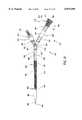
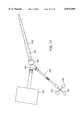
- FIG. 1schematically illustrates a cardiac access system employing the endoaortic partitioning catheter of the present invention.
- FIG. 2is a schematic partly cut-away representation of a patient's heart with the endoaortic partitioning catheter of the present invention placed within the ascending aorta.
- FIG. 3is a transverse cross-sectional view of the occluding catheter shown in FIG. 2 taken along the lines 3--3.
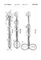
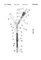
- FIG. 4.is an enlarged view, partially in section, of the retrograde cardioplegia delivery catheter and the pulmonary venting catheter shown in FIG. 1.
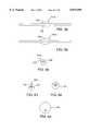
- FIG. 5Ais a longitudinal cross section of a first embodiment of the endoaortic partitioning catheter of the present invention.
- FIG. 5Bis a lateral cross section of the catheter of FIG. 5A taken along the lines 5B--5B.
- FIG. 5Cis a lateral cross section of the catheter of FIG. 5A taken along the lines 5C--5C.
- FIG. 5Dis a detail drawing showing the construction of section 5D--5D of the catheter of FIG. 5A.
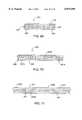
- FIG. 6Ais a lateral side view of a second embodiment of the endoaortic partitioning catheter.
- FIG. 6Bis a lateral cross section of the catheter of FIG. 6A taken along the lines 6B--6B.
- FIG. 6Cis a lateral cross section of the catheter of FIG. 6A taken along the lines 6C--6C.
- FIG. 7Ais a longitudinal cross section of a third embodiment of the endoaortic partitioning catheter having piezoelectric pressure transducers.
- FIG. 7Bis a lateral cross section of the catheter of FIG. 7A taken along the lines 7B--7B.
- FIG. 7Cis a lateral cross section of the catheter of FIG. 7A taken along the lines 7C--7C.
- FIG. 8Ais a longitudinal cross section of a fourth embodiment of the endoaortic partitioning catheter having a variable length occlusion balloon with the occlusion balloon deflated.
- FIG. 8Bis a longitudinal cross section of the catheter of FIG. 8A with the occlusion balloon inflated in an elongated position.
- FIG. 8Cis a longitudinal cross section of the catheter of FIG. 8A with the occlusion balloon inflated in a shortened position.
- FIG. 8Dshows the proximal end of an alternate embodiment of the catheter of FIG. 8A.
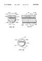
- FIG. 9Ais a side view, partially in section, of a fifth embodiment of the endoaortic partitioning catheter having a twisted low-profile occlusion balloon.
- FIG. 9Bis a longitudinal cross section of the catheter of FIG. 9A with the occlusion balloon inflated.
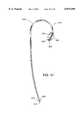
- FIG. 10Ais a front view of a sixth embodiment of the endoaortic partitioning catheter having a precurved distal end.
- FIG. 10Bis a side view of the catheter of FIG. 10A.
- FIG. 10Cis a lateral cross section of the catheter of FIG. 10A taken along the lines 10C--10C.
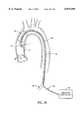
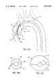
- FIG. 11is a schematic partly cut-away representation of a patient's aortic arch with the endoaortic partitioning catheter of FIG. 10A positioned in the ascending aorta.
- FIG. 12Ais a front view of a seventh embodiment of the endoaortic partitioning catheter having a precurved distal end.
- FIG. 12Bis a side view of the catheter of FIG. 12A.
- FIG. 12Cis a lateral cross section of the catheter of FIG. 12A taken along the lines 12C--12C.
- FIG. 13is a schematic partly cut-away representation of a patient's aortic arch with the endoaortic partitioning catheter of FIG. 12A positioned in the ascending aorta.
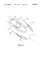
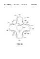
- FIG. 14is a front view of an eighth embodiment of the endoaortic partitioning catheter having an asymmetric aortic occlusion balloon.
- FIG. 15is a schematic partly cut-away representation of a patient's aortic arch with an endoaortic partitioning catheter having a concentric occlusion balloon positioned in the ascending aorta.
- FIG. 16is a schematic partly cut-away representation of a patient's aortic arch with an endoaortic partitioning catheter having an eccentric occlusion balloon positioned in the ascending aorta.
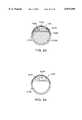
- FIG. 17is a front view of an ninth embodiment of the endoaortic partitioning catheter having an eccentric aortic occlusion balloon.
- FIG. 18Ais a front view of a tenth embodiment of the endoaortic partitioning catheter having an eccentric aortic occlusion balloon.
- FIG. 18Bis an end view of the catheter of FIG. 18A.
- FIG. 19Ais a front view of an eleventh embodiment of the endoaortic partitioning catheter having a nondistensible aortic occlusion balloon.
- FIG. 19Bis an end view of the catheter of FIG. 19A.
- FIG. 19Cis a side view of the catheter of FIG. 19A with the occlusion balloon wrapped around the catheter shaft.
- FIG. 19Dis an end view of the catheter of FIG. 19C.
- FIG. 20Ais a front view of a twelfth embodiment of the endoaortic partitioning catheter having a nondistensible aortic occlusion balloon.
- FIG. 20Bis an end view of the catheter of FIG. 20A.
- FIG. 20Cis a side view of the catheter of FIG. 20A with the occlusion balloon wrapped around the catheter shaft.
- FIG. 20Dis an end view of the catheter of FIG. 20C.
- FIG. 21is a schematic partly cut-away representation of a patient's aortic arch with an endoaortic partitioning catheter having a shaped occlusion balloon positioned in the ascending aorta.
- FIG. 22is a schematic partly cut-away representation of a patient's aortic arch with an endoaortic partitioning catheter having a shaped occlusion balloon positioned in the ascending aorta.
- FIG. 23Ais a schematic partly cut-away representation of a patient's aortic arch with an endoaortic partitioning catheter having a shaped occlusion balloon positioned in the ascending aorta.
- FIG. 23Bis a transverse cross section of the shaped occlusion balloon of FIG. 23A.
- FIG. 24is a schematic partly cut-away representation of a patient's aortic arch with an endoaortic partitioning catheter having a shaped occlusion balloon positioned at the apex of the aortic arch.
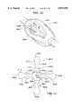
- FIG. 25Aillustrates an endoaortic partitioning catheter with a curved tip for de-airing the heart and ascending aorta.
- FIG. 25Billustrates an alternate embodiment of an endoaortic partitioning catheter for de-airing the heart and ascending aorta.
- FIG. 26illustrates an endoaortic partitioning catheter having a dumbbell-shaped occlusion balloon for centering the catheter tip within the ascending aorta.
- FIG. 27illustrates an endoaortic partitioning catheter having a steerable distal tip for centering the catheter tip within the ascending aorta.
- FIG. 28illustrates an endoaortic partitioning catheter including a fiberoptic bundle for transillumination of the aortic wall and/or for facilitating non-fluoroscopic placement of the catheter.
- FIG. 29illustrates an endoaortic partitioning catheter having an inflatable bumper balloon for protecting the aortic wall from the catheter tip and for facilitating non-fluoroscopic placement of the catheter.
- FIG. 30Ais a rear three-quarter view of a frictional locking suture ring for use with the endoaortic partitioning catheter.
- FIG. 30Bis a front three-quarter view of the frictional locking suture ring of FIG. 30A.
- FIG. 31is a front view of a dual function arterial cannula and introducer sheath for use with the endoaortic partitioning catheter.
- FIG. 32is a cross sectional view of the hemostasis fitting of the dual function arterial cannula and introducer sheath of FIG. 31.
- FIG. 33illustrates the cannula of FIG. 31 with an endoaortic partitioning catheter introduced into the catheter insertion chamber.
- FIG. 34illustrates the cannula of FIGS. 31 and 32 with the endoaortic partitioning catheter introduced into the patient's femoral artery.
- FIGS. 35A-35Cillustrate an endoaortic partitioning catheter having a steerable distal tip with a multichamber balloon for centering the catheter tip within the ascending aorta.
- FIG. 36illustrates a multifunction embodiment of the endoaortic partitioning catheter combined with a dual function arterial cannula and introducer sheath and a frictional locking suture ring.
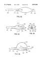
- FIG. 37shows a balloon having a first, high friction portion and a second, low friction portion.
- FIG. 38is an end view of the balloon of FIG. 37.
- FIG. 39is an end view of the balloon of FIG. 37 in an expanded state.
- FIG. 40is an isometric view of a second preferred balloon having a first, low friction portion and a second, high friction portion.
- FIG. 41is an end view of the balloon of FIG. 40.
- FIG. 42is a side view of an aorta with clamps positioned on both sides of the occluding member to prevent migration of the occluding member;
- FIG. 43is a plan view of the clamp of FIG. 42.
- FIG. 44Ais a side view of an aorta with the clamp of FIG. 42 positioned around the aorta and a balloon trapped by the clamp in the aorta.
- FIG. 44Bis a plan view of an intermediate wall positioned in an indentation of the balloon of FIG. 44A.
- FIG. 45is a partial cross-sectional view of the delivery cannula of FIGS. 33 and 34 with a shaft displacing mechanism.
- FIG. 46is a side view of an aorta with the shaft displaced in an outward direction so that the shaft engages a radially inner wall of the aorta.
- FIG. 47is a side view of an aorta with a shaft having a two-bend configuration displaced in an inward direction so that the shaft of FIG. 46 engages a radially outer wall of the aorta.
- FIG. 48is a side view of an aorta with a shaft having a hook-shaped portion displaced in an outward direction so that the shaft engages a radially inner wall of the aorta.
- FIG. 49is a side view of an aorta with the shaft of FIG. 48 displaced in an inward direction so that the shaft engages a radially outer wall of the aorta.
- FIG. 50is a partial cross-sectional side view of a container containing a solution and a mandrel partially submerged in the solution.
- FIG. 51is a plan view of the container and mandrel of FIG. 50.
- FIG. 52is a cross-sectional view of a distal end of a balloon connected to a distal end of a shaft.
- FIG. 53is a cross-sectional view of the balloon of FIG. 52 with the proximal end of the balloon connected to the shaft and the balloon in a collapsed position.
- FIG. 54is a cross-sectional view of the balloon of FIG. 53 along line E--E.
- FIG. 55is a cross-sectional view of the balloon of FIG. 53 in an expanded position.
- FIG. 56is a side view of the distal end of the shaft with the balloon of FIGS. 53-55 in the expanded position.
- FIG. 57is another side view of the distal end of the shaft and balloon of FIG. 56.
- FIG. 58is a side view of another mandrel used for forming an asymmetric balloon.
- FIG. 59is another side view of the mandrel of FIG. 58.
- FIG. 60is an end view of the mandrel of FIGS. 58 and 59.
- FIG. 61is a cross-sectional view of a balloon manufactured with the mandrel of FIGS. 58-60 with the balloon in a partially expanded shape.
- FIG. 62is a cross-sectional view of the balloon of FIGS. 58-60 with the balloon in a more fully expanded shape.
- FIG. 63is a cross-sectional view of the balloon of FIGS. 58-60 with the balloon in the expanded shape.
- FIG. 64is a side view of a trifurcated end of the shaft with one of the independent shafts having a bellows connection.
- FIG. 65is a cross-sectional view of the three lumen portion of the shaft of FIG. 64 along line F--F.
- FIG. 66is a cross-sectional view of a cannula having a reinforced section coupled to a body.
- FIG. 67is a cross-sectional view of a coated elongate member wrapped around a mandrel.
- FIG. 68is a cross-sectional view of the coated elongate member of FIG. 67 after heating and removal from the mandrel.
- FIG. 69is a cross-sectional view of a second construction for the reinforced section.
- FIG. 70is a cross-sectional view of a third construction for the reinforced section.
- FIG. 71is a cross-sectional view of a fourth construction for the reinforced section.
- FIG. 72is a cross-sectional view of a fifth construction for the reinforced section.
- FIG. 73is a cross-sectional view of a sixth construction for the reinforced section.
- FIG. 74is a cross-sectional view of a seventh construction for the reinforced section.
- FIG. 75is a cross-sectional view of a eighth construction for the reinforced section.
- FIG. 76is a cross-sectional view of a ninth construction for the reinforced section.
- FIG. 77illustrates an arterial return cannula having a lumen with an aortic occlusion catheter slidably received in the lumen.
- FIG. 78is partial a cross-sectional view of the arterial return cannula of FIG. 77.
- FIG. 79is an exploded view of FIG. 78.
- FIG. 80is a cross-sectional view of a tenth construction for the reinforced section having a coated elongate member wrapped around a mandrel and a member positioned against the coated elongate member.
- FIG. 81is a longitudinal cross-sectional view of the tenth construction of FIG. 80 around line M--M.
- FIG. 82is a cross-sectional view of the tenth construction after fusing together the member and coated elongate member.
- FIG. 83is a cross-sectional view of an eleventh construction for a reinforced section having a member positioned within a coated elongate member.
- FIG. 84is a cross-sectional view of the eleventh construction for a reinforced tube after fusing together the member and coated elongate member.
- FIG. 85is a cross-sectional view of a twelfth construction for the reinforced section.
- FIG. 86is a longitudinal cross-sectional view of the twelfth construction of FIG. 85 around line N--N.
- FIG. 87shows an aortic occlusion catheter having one of the reinforced sections disclosed herein.
- the inventionprovides a cardiac access system including an endovascular device for partitioning the ascending aorta, as well as a system for selectively arresting the heart, which are useful in performing a variety of cardiovascular, pulmonary, neurosurgical, and other procedures.
- the procedures with which the invention will find useinclude repair or replacement of aortic, mitral, and other heart valves, repair of septal defects, pulmonary thrombectomy, electrophysiological mapping and ablation, coronary artery bypass grafting, angioplasty, atherectomy, treatment of aneurysms, myocardial drilling and revascularization, as well as neurovascular and neurosurgical procedures.
- the inventionis especially useful in conjunction with minimally-invasive cardiac procedures, in that it allows the heart to be arrested and the patient to be placed on cardiopulmonary bypass using only endovascular devices, obviating the need for a thoracotomy or other large incision. Moreover, even in conventional open-chest procedures, the endovascular aortic partitioning device of the invention will frequently find use where an external cross-clamp would raise substantial risks of embolus release due to calcification or other aortic conditions.
- FIG. 1schematically illustrates the overall cardiac accessing system of the invention and the individual components thereof.
- the accessing systemincludes an elongated aortic occlusion or endoaortic partitioning catheter 10 which has an expandable member 11 on a distal portion of the catheter which, when inflated as shown, occludes the ascending aorta 12 to separate or partition the left ventricle 13 and upstream portion of the ascending aorta from the rest of the patient's arterial system and securely positions the distal end of the catheter within the ascending aorta.
- an elongated aortic occlusion or endoaortic partitioning catheter 10which has an expandable member 11 on a distal portion of the catheter which, when inflated as shown, occludes the ascending aorta 12 to separate or partition the left ventricle 13 and upstream portion of the ascending aorta from the rest of the patient's arterial system and securely positions the distal end of the catheter within the ascending aor
- a cardiopulmonary bypass system 18removes venous blood from the femoral vein 16 through the blood withdrawal catheter 17 as shown, removes CO 2 from the blood, oxygenates the blood, and then returns the oxygenated blood to the patient's femoral artery 15 through the return catheter 19 at sufficient pressure so as to flow throughout the patient's arterial system except for the portion blocked by the expanded occluding member 11 on the aortic occluding catheter 10.
- the aortic occluding catheter 10has an infusion lumen 40 for antegrade delivery of a fluid containing cardioplegic agents directly into the aortic root 12 and subsequently into the coronary arteries 52, 53 (shown in FIG. 2) to paralyze the patient's myocardium.
- a retrograde cardioplegia balloon catheter 20may be disposed within the patient's venous system with the distal end of the catheter extending into the coronary sinus 21 (shown in FIG. 4) to deliver a fluid containing cardioplegic agents to the myocardium in a retrograde manner through the patient's coronary venous system to paralyze the entire myocardium.
- the elongated occluding catheter 10extends through the descending aorta to the left femoral artery 23 and out of the patient through a cut down 24.
- the proximal extremity 25 of the catheter 10 which extends out of the patientis provided with a multi-arm adapter 26 with one arm 27 adapted to receive an inflation device 28.
- the adapter 26is also provided with a second arm 30 with main access port 31 through which passes instruments, a valve prosthesis, an angioscope, or to direct blood, irrigation fluid, cardioplegic agents and the like to or from the system.
- a third arm 32is provided for monitoring aortic root infusion pressure at the distal end of the catheter and/or for directing blood, irrigation fluid, and the like to or from the system.
- the third arm 32 of the multi-arm adapter 26is connected to a cardiopulmonary bypass line 33 to vent the patient's heart, particularly the left ventricle, and to recover the blood removed and return it to the patient via the cardiopulmonary bypass system.
- a suitable valve 34is provided to open and close the bypass line 33 and direct the fluid passing through the bypass line to a discharge line 35 or a line 36 to a blood filter and recovery unit 37.
- a return linemay be provided to return any filtered blood to the cardiopulmonary bypass system 18 or other blood conservation system.
- the catheter 10includes an elongated catheter shaft 39 which has a first inner lumen 40 for infusion of a cardioplegic agent in fluid communication with the main access port 31 in the second arm of the adapter 26.
- the infusion lumen 40may be adapted to facilitate the passage of instruments, a valve prosthesis, an angioscope, irrigation fluid, and the like therethrough and out the distal port 41 in the distal end thereof.
- a supporting coil 42may be provided in the distal portion of the first inner lumen 40 to prevent the catheter shaft 39 from kinking when it straightened for initial introduction into the arterial system or when it is advanced through the aortic arch.
- the shaft 39is also provided with a second inner lumen 43 which is in fluid communication with the interior of the occluding balloon 11.
- a retrograde cardioplegia balloon catheter 20which is shown in more detail in FIG. 4, is introduced into the patient's venous system through the right internal jugular vein 44 and is advanced through the right atrium 45 and into the coronary sinus 21 through the coronary sinus discharge opening 46 in the right atrium.
- the retrograde catheter 20is provided with a balloon 47 on a distal portion of the catheter 20 which is adapted to occlude the coronary sinus 21 when inflated.
- a liquid containing a cardioplegic agente.g.
- an aqueous KCl solutionis introduced into the proximal end 48 of the catheter 20, which extends outside of the patient, under sufficient pressure so that the fluid containing the cardioplegic agent can be forced to pass through the coronary sinus 21, through the capillary beds (not shown) in the patient's myocardium, through the coronary arteries 50 and 51 and ostia 52 and 53 associated with the respective coronary arteries into the blocked off portion of the ascending aorta 12 as shown.
- a pulmonary venting catheter 54is also shown in FIG. 4 disposed within the right internal jugular vein 44 and extending through the right atrium 45 and right ventricle 55 into the pulmonary trunk 56.
- the pulmonary venting catheter 54may be introduced through the left jugular.
- the catheter 54passes through tricuspid valve 57 and pulmonary valve 58.
- An inflatable occluding balloon 60may be provided as shown on a distal portion of the pulmonary venting catheter 54 which is inflated to occlude the pulmonary trunk 56 as shown.
- the pulmonary venting catheter 54has a first inner lumen 61 which extends from the distal end of the catheter to the proximal end of the catheter which vents fluid from the pulmonary trunk 56 to outside the patient's body either for discharge or for passage to the blood recovery unit and thereby decompresses the left atrium 14 through the pulmonary capillary beds (not shown).
- the catheter 54has a second inner lumen 62 which is adapted to direct inflation fluid to the interior of the inflatable balloon 60.
- the patientis initially placed under light general anesthesia.
- the withdrawal catheter 17 and the return catheter 19 of the cardiopulmonary bypass system 18are percutaneously introduced into the right femoral vein 16 and the right femoral artery 15, respectively.
- An incision 24is also made in the left groin to expose the left femoral artery 23 and the aortic occluding catheter 10 is inserted into the left femoral artery through an incision therein and advanced upstream until the balloon 11 on the distal end of the occluding catheter 10 is properly positioned in the ascending aorta 12.
- bypasscould similarly be established in the left groin and the aortic occlusion catheter put into the right femoral artery.
- the retrograde perfusion catheter 20is percutaneously inserted by a suitable means such as the Seldinger technique into the right internal jugular vein 44 or the subclavian vein and advanced into the right atrium 45 and guided through the discharge opening 46 into the coronary sinus.
- the pulmonary venting catheter 54is advanced through the right or left internal jugular vein 44 or the subclavian vein (whichever is available after introduction of retrograde perfusion catheter 20) into the right atrium 45, right ventricle 55, and into the pulmonary trunk 56.
- the occluding balloon 60may be inflated if necessary by inflation with fluid passing through the lumen 62 to block the pulmonary trunk 56 and vent blood therein through the lumen 61 where it is discharged through the proximal end of the catheter which extends outside of the patient.
- the occluding balloon 60may be partially inflated with air or CO 2 during introduction for flow-assisted placement.
- venting of the pulmonary trunk 56results in the decompressing of the left atrium 14 and, in turn, the left ventricle.
- the venting catheter 54may be provided with means on the exterior thereof, such as expanded coils as described in U.S. Pat. No. 4,889,137 (Kolobow), which hold open the tricuspid and pulmonary valves and perform the same function of decompressing the left atrium. See also the article written by F. Rossi et. al. in the Journal of Thoracic Cardiovascular Surgery, 1900;100:914-921, entitled "Long-Term Cardiopulmonary Bypass By Peripheral Cannulation In A Model Of Total Heart Failure", which is incorporated herein in its entirety by reference.
- the operation of the cardiopulmonary bypass unit 18is initiated to withdraw blood from the femoral vein 16 through catheter 17, remove CO 2 from and add oxygen to the withdrawn blood and then pump the oxygenated blood through the return catheter 19 to the right femoral artery 15.
- the balloon 11may then be inflated to occlude the ascending aorta 12, causing the blood pumped out of the left ventricle (until the heart stops beating due to the cardioplegic fluid as discussed hereinafter) to flow through the discharge port 41 into the first inner lumen 40 of the occluding catheter.
- the bloodflows through the inner lumen 40 and out the third arm 32 of the adapter 26 into the bypass line 33 and then into the blood filter and blood recovery unit 37 through the valve 34 and line 36.
- the position of the valve 34may be changed to direct the fluid through the discharge line 35.
- a liquid containing a cardioplegic agent such as KClis directed through the infusion lumen 40 of the catheter 10 into the aortic root 12 and subsequently into the coronary arteries 52, 53 to paralyze the patient's myocardium.
- a retroperfusion catheter 20is provided for delivery of the cardioplegic agent
- the balloon 47 on the distal extremity of the catheter 20is inflated to occlude the coronary sinus 21 to prevent fluid loss through the discharge opening 46 into the right atrium 45.
- a liquid containing a cardioplegic agent such as KClis directed through the catheter 20 into the coronary sinus 21 and the pressure of the cardioplegic fluid within the coronary sinus 21 is maintained sufficiently high, (e. g.
- cardioplegic fluid pressure within the coronary sinus 21should be maintained below 75 mm Hg to avoid pressure damage to the coronary sinus 21.
- the heartWith the cardiopulmonary bypass system in operation, the heart completely paralyzed and not pumping, the left atrium and ventricle decompressed and the ascending aorta blocked by the inflated balloon 11 on the occluding catheter 10, the heart is appropriately prepared for a cardiac procedure.
- Inflation of the inflatable member 11 on the distal end of the delivery catheter 10fixes the distal end of the occluding catheter 10 within the ascending aorta 12 and isolates the left ventricle 13 and the upstream portion of the ascending aorta from the rest of the arterial system downstream from the inflatable member.
- the passage of any debris or emboli, solid or gaseous, generated during a cardiovascular procedure to regions downstream from the sitewould be precluded by the inflated balloon 11.
- Fluid containing debris or embolican be removed from the region between the aortic valve and the occluding balloon 11 through the inner lumen 40 of catheter 10.
- a clear, compatible fluide.g.
- an aqueous based fluidsuch as saline delivered through the inner lumen 40 or the cardioplegic fluid discharging from the coronary ostia 52 and 53, may be maintained in the region wherein the cardiovascular procedure is to be performed to facilitate use of an angioscope or other imaging means that allows for direct observation of the cardiac procedure.
- the fluid pressure in the left ventricle 13is maintained sufficiently higher than that in the left atrium to prevent blood from the left atrium from seeping into the left ventricle and interfering with the observation of the procedure.
- FIG. 5Ashows a longitudinal cross section of a first preferred embodiment of the endoaortic partitioning catheter 100 of the present invention.
- the endoaortic partitioning catheter 100 of FIG. 5Ais made with a coaxial construction, which indicates that the catheter 100 is constructed of a first, inner tube 102 within a second, outer tube 104.
- the inner tube 102 and the outer tube 104 of the catheter 100combine to form an elongated shaft 106 that runs from a proximal hub 108 to the distal end of the catheter 100 having an aortic occlusion balloon 110 mounted thereon.
- the length of the shaft 106is such that the catheter 100 can be introduced into the patient's aorta by way of an arterial cutdown or the Seldinger technique into a peripheral artery, such as the femoral or brachial artery, and advanced into the ascending aorta.
- a peripheral arterysuch as the femoral or brachial artery
- the length of the shaft 106is preferably 80 to 125 cm.
- the length of the shaft 106is preferably 20 to 80 cm.
- the inner tube 102 of the catheter 100is a two lumen tube, having a crescent-shaped cardioplegia infusion lumen 112 which wraps around a circular distal pressure lumen 114, as shown in cross section in FIGS. 5B and 5C.
- the cardioplegia infusion lumen 112 and the distal pressure lumen 114are open at the distal end of the catheter 100.
- the cardioplegia infusion lumen 112preferably has a cross sectional area sufficient for delivering a mixture of warm or cooled, oxygenated blood and cardioplegia solution at a rate of from about 200 ml/min to 400 ml/min with an infusion pressure not to exceed 300 mm Hg.
- the cross sectional area of the cardioplegia infusion lumen 112is approximately 5.74 mm 2 (0.00889 in 2 ) for a catheter with a length of about 120-130 cm.
- the cross sectional area of the cardioplegia infusion lumen 112 necessary to deliver the desired flow ratewill vary somewhat depending on the length of the catheter shaft 106 and the ratio of blood to cardioplegic solution in the mixture.
- the distal pressure lumen 114preferably has a cross sectional area sufficient to transmit the pressure within the aortic root along the length of the catheter shaft 106 without excessive damping of the pressure wave.
- a distal pressure lumen 114having an internal diameter of 0.61 mm, and therefore a cross sectional area of 0.29 mm 2 (0.00045 in 2 ), provides the desired pressure signal transmission.
- the outer tube 104 of the catheter 100fits coaxially around the inner tube 102 with an annular space between the two tubes providing a balloon inflation lumen 116, as shown in cross section in FIG. 3C.
- the external diameter of the catheter 100can be made within the range of 8-23 French (Charriere scale), preferably in the range of 8-12 French.
- the outer tube 104has an external diameter of 3.4-3.5 mm or approximately 10.5 French (Charriere scale).
- the outer tube 104has an external diameter of 3.2-3.3 mm or approximately 10 French (Charriere scale).
- An aortic occlusion balloon 110is mounted on the distal end of the catheter 100.
- the aortic occlusion balloon 110has a proximal balloon neck 118 which is sealingly attached to the outer tube 104 and a distal balloon neck 120 which is sealingly attached to the inner tube 102 of the catheter 100 so that the balloon inflation lumen 116 communicates with the interior of the balloon 110.
- the balloon inflation lumen 116has a cross sectional area of approximately 0.5-1.0 mm 2 (0.00077-0.00155 in 2 ) to allow rapid inflation and deflation of the aortic occlusion balloon 110.
- the balloon inflation lumen 116has a cross sectional area of approximately 0.626 mm 2 (0.00097 in 2 ) which allows the occlusion balloon 110 be inflated to a recommended maximum volume of 40 cc with saline solution or saline solution mixed with a radiopaque contrast agent at an inflation pressure of 35 psi in 40 seconds or less, preferably in 20 seconds or less.
- the inflation of the balloonis preferably volume-limited so that, although the transient, peak inflation pressure reaches approximately 35 psi, the inflation pressure decreases to about 10-12 psi to maintain balloon inflation when the balloon reaches its desired inflation volume.
- the balloon inflation lumen 116also allows the occlusion balloon 110 be deflated in 60 seconds or less, preferably in 40 seconds or less.
- the occlusion balloon 110can be inflated and deflated by hand using an ordinary syringe or it can be inflated and deflated using an inflation device which provides a mechanical advantage or that is powered by compressed air or an electric motor.
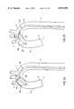
- FIG. 5Dis a detail drawing showing the construction of section 5D--5D of the catheter 100 of FIG. 5A.
- the proximal balloon neck 118is bonded to the distal end of the outer tube 104 in a lap joint.
- the bond between the proximal balloon neck 118 and the outer tube 104 and the bond between the distal balloon neck 120 and the inner tube 102can be formed by adhesive bonding, by solvent bonding or by heat bonding depending on the materials chosen for each component.
- the outer tube 104can be formed from a single continuous extrusion with the material of the aortic occlusion balloon 110.
- the proximal hub 108 of the catheter 100has a luer fitting balloon inflation port 122 that is sealingly connected to the balloon inflation lumen 116, a luer fitting pressure monitoring port 124 that is sealingly connected to the distal pressure lumen 114, and an infusion port 126 that is sealingly connected to the cardioplegia infusion lumen 112.
- the proximal hub 108may be joined to the proximal ends of the inner tube 102 and the outer tube 104 by adhesive bonding, by insert molding or by other known processes.
- the aortic occlusion balloon 110is shown as having a generally spherical geometry in the unexpanded state 110, as well as a generally spherical geometry in the expanded or inflated state 110'.
- Other possible geometries for the balloon in the unexpanded state 110include cylindrical, oval or football-shaped, eccentric, asymmetric or other shaped balloons. Some of these variations are further described below.
- the balloon 110is made of an elastomeric material that expands elastically from the uninflated to the inflated state.
- Preferred materials for the balloon 110include latex, silicone, and polyurethane, chosen for their elasticity, strength and biocompatibility for short term contact with the blood and body tissues.
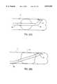
- FIG. 6Ashows a lateral side view of a second preferred embodiment of the endoaortic partitioning catheter 200.
- the inner tube 202has been made with a D-shaped cardioplegia infusion lumen 212 and a D-shaped distal pressure lumen 214.
- the choice of D-shaped lumens in the inner tube 202makes it possible to maximize the diametrical clearance within the cardioplegia infusion lumen 212 for a given cross sectional area, as compared to the crescent-shaped cardioplegia infusion lumen 112 of FIG. 5C.
- This variation of the catheter 200may be preferable when catheters or other instruments are to be introduced to the heart and its associated blood vessels through the cardioplegia infusion lumen 212.
- the occlusion balloon 210 of this embodimenthas an ellipsoidal or football-shaped deflated profile which is imparted by the balloon molding process.
- the wall thickness of the molded balloon 210 in its deflated stateis typically about 0.090-0.130 mm.
- the deflated balloon 210has a diameter of approximately 12 mm before it is folded, although deflated balloon diameters of 3 to 20 mm are possible.
- the inflated balloon 210'assumes a roughly spherical shape with a maximum diameter of approximately 40 mm when inflated.
- the football shape of the molded balloonhas been shown to be advantageous in that the deflated balloon 210 has a deflated profile which is less bulky and smoother than for other balloon geometries tested. This allows the deflated balloon 210 to be folded and more easily inserted through a percutaneous puncture into the femoral artery or through an introducer sheath or a dual function arterial cannula and introducer sheath.
- the balloon 210is preferably made of an elastomeric material such as latex, silicone, or polyurethane.
- the football-shaped balloonhas an internal geometry determined by a positive dip molding mandrel with a radius of curvature in the central portion of the balloon of approximately 1.0 inch with a maximum diameter in the center of the balloon of about 0.5 inch.
- the curvature of the central portion of the balloonhas a smoothly radiused transition, for example with a radius of about 0.25 inch, to the proximal and distal balloon sleeves, which are sized to fit snugly onto the exterior of the chosen diameter catheter shaft.
- FIG. 7Ashows a longitudinal cross section of a third preferred embodiment of the endoaortic partitioning catheter 300.
- the catheter 300 of this embodimenthas a coaxial construction having a single lumen inner tube 302 surrounded by a single lumen outer tube 304.
- the single lumen inner tube 302has a circular cardioplegia infusion lumen 312 that is connected on its proximal end to the infusion port 326 of the proximal hub 308 of the catheter 300.
- the cardioplegia infusion lumen 312is open at the distal end of the catheter 300.
- the single lumen outer tube 304 of the catheter 300fits coaxially around the inner tube 302 with an annular space between the two tubes providing a balloon inflation lumen 316.
- the balloon inflation lumen 316is connected on its proximal end to the balloon inflation port 322 of the proximal hub 308.
- the aortic root pressure monitoring functionis fulfilled by a distal pressure transducer 330 mounted at the distal tip 332 of the catheter 300.
- the distal pressure transducer 330electronically monitors the aortic root pressure and transmits a signal along signal wires 334 and 336 to electrical connections 338 and 340 within an electrical connector 324 on the proximal hub 308 of the catheter 300.
- the electrical connectoris adapted to be connected to an electronic pressure monitor which displays an analog or digital indication of the pressure at the distal end 332 of the catheter 300.
- the distal pressure transducer 330is preferably a piezoelectric pressure transducer which creates a voltage signal indicative of the external fluid pressure exerted on the transducer 330.
- piezoelectric materials suitable for construction of the distal pressure transducer 330include piezoelectric polymers such as polyvinylidene bifluoride or KynarTM (Elf Atochem SA), or piezoelectric ceramics such as lead barium titanate, zirconium barium titanate or other commercially available piezoelectric materials.
- the geometry of the distal pressure transducer 330may be a ring encircling the distal tip 332 of the catheter 300, as shown in FIGS. 7A and 7B. Alternatively, a small patch of the piezoelectric material may be mounted on one side of the distal tip 332 of the catheter 300.
- the distal pressure transducer 330preferably has a pressure sensing range from about -75 to 300 mm Hg or greater (-1.5 to 5.7 psi) so as to be able to measure root pressure during cardioplegia infusion and during venting of the aortic root.
- a balloon pressure monitoring transducer 350may also be mounted within the balloon 310 of the catheter 300 for monitoring the inflation pressure of the balloon 310.
- the balloon pressure monitoring transducer 350electronically monitors the balloon inflation pressure and transmits a signal along signal wires 352 and 354 to electrical connections 356 and 358 within the electrical connector 324 on the proximal hub 308 of the catheter 300.
- the balloon pressure monitoring transducer 350is preferably a piezoelectric pressure transducer which creates a voltage signal indicative of the external fluid pressure exerted on the transducer 350, made for example from one the piezoelectric polymers or piezoelectric ceramics designated above in connection with the distal pressure transducer 330.
- the balloon pressure monitoring transducer 350preferably has a pressure sensing range from about -760 to 300 mm Hg or greater (-15 to 35 psi) so as to be able to measure balloon pressure during inflation and deflation of the occlusion balloon 310.
- the balloon pressure monitoring transducer 350can be used to monitor internal balloon pressure to make sure that the occlusion balloon 310 has been inflated to proper pressure to insure reliable occlusion of the ascending aorta.
- the balloon pressure monitoring transducer 350can also be used to determine when the occlusion balloon 310 has contacted the interior wall of the ascending aorta by monitoring for a spike in the inflation pressure within the balloon or for an inflection point in the pressure/volume curve while inflating.
- a safe inflation volumecan be determined for each individual patient by a protocol wherein the occlusion balloon 310 is inflated until it contacts the interior wall of the ascending aorta, then a set volume of inflation fluid is added to create a reliable seal to occlude the aortic lumen.
- the protocol for inflationcould include determining when the occlusion balloon 310 contacts the aortic wall and incrementally increasing the pressure a set amount to form a seal.
- the pressure transducer 350monitors the pressure in the balloon 310 and transmits the pressure information to a pressure monitor 353 via signal wires 352, 354 and electrical connections 356, 358.
- the pressure monitor 353is also coupled to a source of inflation fluid 355 for determining an amount of inflation fluid injected into the balloon 310.
- the pressure monitor 353is configured to determine the rate of pressure increase relative to the fluid volume injected in the balloon 351 from the fluid source 355.
- the pressure monitor 353determines when a pressure spike in the pressure vs. fluid volume is detected. The pressure spike generally indicates that the balloon 310 has engaged the aortic lumen at which point the pressure increases more rapidly with respect to the fluid volume.
- the slope of the pressure spike which triggers the pressure monitor 353depends upon a number of factors including the size, shape and elasticity of the balloon 310. It is contemplated that the magnitude of the pressure spike may be determined empirically by testing balloons with various size passageways. After the pressure spike is detected, the pressure monitor 353 sends a signal to the source of inflation fluid 355 to either add a predetermined amount of fluid or to add fluid until a predetermined increase in pressure is sensed. The predetermined amount of fluid and/or predetermined increase in pressure both add an additional amount of holding force to prevent migration of the balloon while minimizing distention of the aorta.
- the catheterincludes a proximal pressure transducer 331 which monitors the pressure on a proximal side of the balloon 351 and transmits a signal to the pressure monitor 353 via wires 339, 341.
- the pressure transducer 330 and proximal pressure transducer 331are coupled to the pressure monitor 353 which monitors the pressures and, furthermore, determines a pressure differential between the transducers 330, 331.
- the pressure monitor 353preferably includes an alarm 357, which may be a visual or audible alarm, which tells the user that the pressure differential measured by the transducers 330, 331 exceeds a predetermined threshold.
- the pressure on one or both sides of the balloon 351is adjusted so that the pressure differential does not exceed the predetermined threshold.
- the catheter 300delivers cardioplegic fluid through the infusion port from a source of cardioplegic fluid 359.
- the delivery of cardioplegic fluid from the source of cardioplegic fluid 359may be adjusted so that the pressure differential does not exceed the predetermined threshold.
- the pressure on the proximal side of the balloonmay be adjusted so that the pressure differential is below the threshold differential pressure.
- 7Amay be used with any other occluding member or balloon and are generally directed to techniques for minimizing migration of occluding members.
- pressure transducers 330, 350, 331is preferred, any other devices for measuring the balloon and fluid pressures may be used without departing from the scope of the invention.
- the signal wires 334, 336, 339, 341, 352, 354 from the pressure transducers 330, 350, 331extend through the annular inflation lumen 316 between the inner tube 302 and the outer tube 304.
- the signal wires 334, 336, 352, 354, 339, 341may be laid loosely in the inflation lumen 316 with some slack, or they may be spiraled around the inner tube 302 so that they do not adversely affect the bending characteristics of the catheter 300.
- the signal wiresmay be embedded in the wall of the inner tube 302, either during the extrusion process or in a post-extrusion operation.
- the signal wiresmay be provided as parallel pairs, twisted pairs or coaxial cables, as required.
- a distal pressure transducer 330 for monitoring aortic root pressureeliminates the need for a separate pressure monitoring lumen in the catheter as provided in the embodiments of FIGS. 5A and 6A. This allows a reduction in the catheter external diameter without sacrificing catheter performance in terms of the cardioplegia flow rate in the infusion lumen 312 and the speed of balloon inflation and deflation through the balloon inflation lumen 316.
- a 10 French (3.3 mm external diameter) catheter constructed according to this designprovides a flow rate and balloon inflation performance comparable to a 10.5 French (3.5 mm external diameter) catheter constructed with a separate pressure monitoring lumen. Reducing the external diameter of the catheter in this way has a number of clinical advantages.
- the smaller diameter catheterwill be easier to introduce into a patient's femoral, brachial or other artery by either the Seldinger technique or by an arterial cutdown or by insertion through an introducer sheath. It will also be possible to introduce the smaller diameter catheter into smaller arteries, as encountered in smaller patients, particularly female and pediatric patients. This will increase the clinical applicability of the catheter and the method for its use to a greater patient population. In all patients, the smaller diameter catheter will cause less trauma to the artery it is introduced through, thereby reducing the likelihood of complications, such as bleeding or hematoma at the arterial access site. The smaller diameter catheter will also be particularly advantageous when used in conjunction with the dual function arterial cannula and introducer sheath described below in relation to FIGS.
- the external diameter of an endoaortic partitioning catheter for use with warm blood cardioplegiacan be reduced to 8 to 10 French (2.7-3.3 mm external diameter) and for use with crystalloid cardioplegia can be reduced to 7 to 9 French (2.3-3.0 mm external diameter).
- FIGS. 8A-8C and 9A-9BTwo embodiments of coaxial-construction catheters with self-collapsing occlusion balloons are shown in FIGS. 8A-8C and 9A-9B.
- FIG. 8Ashows a transverse cross section of a coaxial-construction endoaortic partitioning catheter 400 in which the inner tube 402 and the outer tube 404 are axially movable with respect to one another.
- the inner tube 402has a cardioplegia infusion lumen 412 and a pressure monitoring lumen 414.
- the inner tube 402is connected to a first proximal hub 430 with luer fitting connections 426 and 424 in communication with the cardioplegia infusion lumen 412 and the pressure monitoring lumen 414, respectively.
- the outer tube 404fits coaxially around the inner tube 402 with an annular space between the two tubes providing a balloon inflation lumen 416.
- the outer tube 404is connected to a second proximal hub 432 with a luer fitting connection 422 for the balloon inflation lumen 416.
- the inner tube 402passes through the second proximal hub 432 exiting through a sliding fluid seal 440 that allows axial movement of the inner tube 402 with respect to the second proximal hub 432 and the outer tube 404.
- the sliding fluid seal 440is a type of compression fitting known in the industry as a Tuohy-Borst adapter.
- the Tuohy-Borst adapter 440has a compressible tubular or ring-shaped elastomeric seal 442 that fits within a bore 446 on the proximal end of the second proximal hub 432.
- a threaded compression cap 444fits onto the proximal end of the second proximal hub 432. When the compression cap 444 is tightened, it compresses the elastomeric seal 442 axially, which causes the lumen 448 of the seal 442 to narrow and seal against the inner tube 402.
- the Tuohy-Borst adapter 440can also be used to lock the position of the inner tube 402 with respect to the second proximal hub 432 and the outer tube 404 by tightening the compression cap 444 until the friction between the elastomeric seal 442 and inner tube 402 effectively locks them together to prevent axial movement between the two.
- a sliding fluid seal 440is combined with a locking mechanism 450 to lock the inner tube 402 with respect to the outer tube 404 to prevent axial movement between the two.
- the locking mechanism 450may comprise a threaded shaft 452 in alignment with the inner tube 402 and a lock nut 454 threaded onto the shaft 452. By turning the lock nut 454 on the threaded shaft 452, the user can adjust the position of the inner tube 402 relative to the outer tube 404 to increase or decrease the length of the occlusion balloon 410 when inflated.
- the sliding fluid seal 440may be a Tuohy-Borst adapter as described above or, because a separate locking mechanism 450 is provided, it may be a simple sliding seal, such as an O-ring or wiper seal 456, as illustrated.
- FIG. 6Ashows the inner tube 402 of FIG.
- FIG. 6Cshows the endoaortic partitioning catheter 400 of FIGS. 1A and 1B with the inner tube 402 in its farther proximal position with respect to the outer tube 404 and the occlusion balloon 410" inflated.
- the inner tube 402 and the outer tube 404places a compressive force on the ends of the occlusion balloon 410" which restricts the expansion of the balloon somewhat in the axial direction.
- This featureallows the user to select the inflated diameter of the balloon and the axial length of the balloon, and therefore the length of contact with the aortic wall, within certain ranges, as well as allowing the balloon to be more fully collapsed when deflated for insertion and removal.
- the range of useful balloon diameters of the occlusion balloon 410 for use in an adult human ascending aortais from above 20 to 40 cm. Other ranges of balloon diameters may be needed for pediatric patients or nonhuman subjects.
- This featurewill find particular utility when the endoaortic partitioning catheter 400 is used while performing surgery or other interventional procedures on the aortic valve, or within the aortic root or ascending aorta. To facilitate the surgery, it will be important to provide as much clearance as possible between the inflated occlusion balloon 410" and the aortic valve to allow manipulation of instruments within the ascending aorta while at the same time being sure that the occlusion balloon 410" does not occlude the brachiocephalic artery.
- the inner tube 402would be adjusted to its farthest proximal position with respect to the outer tube 404 before the occlusion balloon 410" is inflated in order to restrict the size of the balloon 410" as much as possible in the axial direction.
- FIG. 9Ashows a transverse cross section of a coaxial-construction endoaortic partitioning catheter 500 in which the inner tube 502 and the outer tube 504 are rotatable with respect to one another.
- the inner tube 502has a cardioplegia infusion lumen 512 connected to a luer fitting connection 526 on the proximal hub 508.
- the outer tube 504fits coaxially around the inner tube 502 with an annular space between the two tubes providing a balloon inflation lumen 516 which communicates with a luer fitting connection 522 on the proximal hub 508.
- the outer tube 504is connected to a rotating collar 540 which is rotatably and slidably mounted on the distal end of the proximal hub 508.
- An aortic occlusion balloon 510is mounted on the distal end of the catheter 500 with the proximal balloon neck 518 sealingly attached to the outer tube 504 and the distal balloon neck 520 sealingly attached to the inner tube 502 of the catheter 500 so that the balloon inflation lumen 516 communicates with the interior of the balloon 510.
- the occlusion balloon 510is preferably made of an elastomeric material, such as latex, silicone or polyurethane.
- a piezoelectric distal pressure transducer 530 mounted at the distal tip of the catheter 500electronically monitors the aortic root pressure and transmits a signal along signal wires 532 and 534 to electrical connections 536 and 538 within an electrical connector 524 on the proximal hub 508 of the catheter 500.
- the rotating collar 540can be rotated with respect to the proximal hub 508 to twist the deflated occlusion balloon 510 around the inner tube 502.
- the rotating collar 540can also be moved proximally with respect to the proximal hub 508 to tension the balloon to create an even lower deflated profile.
- the rotating collar 540is counter rotated to release the balloon from its twisted state before inflation.
- the catheter 500 with the fully inflated occlusion balloon 510'is shown in FIG. 9B.
- the occlusion balloon 510is deflated and the rotating collar 540 is again rotated and moved proximally with respect to the proximal hub 508 to twist the deflated occlusion balloon 510 around the inner tube 502 to create a lower deflated profile for removal of the catheter 500.
- the shaft of the cathetermay take one of a variety of forms.
- the shaft of the cathetermay be a straight length of flexible tubing, made from a highly flexible plastic or elastomer, such as polyurethane, polyethylene, polyvinylchloride or a polyamide polyether block copolymer, preferably in the range of 35 to 72 Shore D durometer.
- Another variation of this embodimentwould be to provide a straight shaft with zones of varying stiffness graduated from a stiff proximal section to a highly flexible distal section.
- variable stiffness shaftcould be made by welding tubing segments of different stiffness polymers end-to-end to create two, three or more zones of stiffness.
- the catheter shaftcould be made with a stiff proximal section of a polyamide polyether block copolymer with a hardness of 63 to 72 Shore D durometer, an intermediate section of a softer grade of the same polymer with a hardness of 55 to 63 Shore D durometer, and a distal section of a very soft grade of the polymer with a hardness of 35 to 55 Shore D durometer.
- an especially flexible soft tip with a hardness of 25 to 35 Shore D durometermay be molded or heat bonded to the distal end of the catheter shaft.
- the shaftcan be made with continuously graduated stiffness from the proximal to distal end using a process such as total intermittent extrusion to gradually change the stiffness along the length of the catheter shaft.
- a processsuch as total intermittent extrusion to gradually change the stiffness along the length of the catheter shaft.
- either or both of the inner tube and the outer tubemay be made with varying stiffness to achieve the overall effect of a graduated stiffness catheter.
- either or both of the inner tube and the outer tubemay be reinforced with wire or filament braiding or coils for increased stiffness, torque control or kink resistance.
- the polymeric material of the shaftis preferably loaded with a radiopaque filler, such as bismuth subcarbonate, bismuth oxychloride, bismuth trioxide, barium sulfate or another radiopaque material.
- a radiopaque fillersuch as bismuth subcarbonate, bismuth oxychloride, bismuth trioxide, barium sulfate or another radiopaque material.
- the shaftis preferably loaded with a level of between about 10 and 30 percent of radiopaque filler by weight, preferably about 20%.
- the soft tipmay be loaded with a higher percent of radiopaque filler, such as about 30 to 35 percent by weight for greater fluoroscopic visibility.
- radiopaque markersfor example rings of gold, platinum, tin, tantalum or tungsten alloys may be attached to the catheter shaft at various points along the length, especially at the tip of the catheter for fluoroscopic visibility.
- the highly flexible catheterwould be advanced through the patient's descending aorta and into the ascending aorta with a stiffer guidewire and/and or a dilator placed in the infusion lumen of the catheter to provide stiffness for advancing and maneuvering the catheter into position.
- the stiffness of the proximal shaft segmentwill assist in advancing and maneuvering the catheter into position.
- a curved guidewire or dilatormay be used to assist in forming the catheter shaft to the curve of the aortic arch.
- the catheter shaftmay be made of a somewhat stiffer polymer so that the distal segment of the catheter can be precurved to a configuration that assists in maneuvering the occlusion balloon into the correct position within the ascending aorta.
- the precurved catheter shaftmay also be made with varying degrees of stiffness graduated from a stiff proximal segment to a flexible distal segment.
- the shaftwould be made of slightly higher durometer grades of a flexible plastic or elastomer, such as polyurethane, polyethylene, polyvinylchloride or a polyamide polyether block copolymer, preferably in the range of 55 to 72 Shore D durometer.
- a short, very flexible tip of a low durometer polymerpreferably in the range of 25 to 35 Shore D durometer, can be added to the distal end to make it less traumatic to the arterial walls and the aortic valve which it may come in contact with.
- Two variations of precurved catheter shaftsare shown in FIGS. 10A-10C and 11A-11C. For the purposes of illustration, these embodiments are shown as built in a multilumen construction, but the precurved shafts can as well be made in one of the coaxial constructions previously described.
- FIG. 10AOne preferred embodiment of an aortic partitioning catheter 600 with a precurved shaft is shown in FIG. 10A.
- the distal portion 604 of the catheter shaft 602is configured to facilitate placement of the occlusion balloon 610 into the ascending aorta.
- the curve of the catheter shaft 602also stabilizes the catheter in the proper position to prevent migration or dislodgement of the inflated occlusion balloon.
- the distal portion 604 of the catheter shaft 602has a curve of approximately 270°-300° of arc.
- the curve of the catheter shaft 602is a compound curve having a first segment 606 of approximately 135° of arc with a radius of curvature of approximately 75-95 mm.
- the occlusion balloon 610is mounted on the third segment 612 of the catheter shaft near the distal end 614 of the catheter 600.
- the third segment 612 of the catheter 600may be straight, so that the total arc subtended by the catheter curve 604 is approximately 270°.
- the third segment 612 of the catheter 600may be angled upward at a point about midway along the third segment 612, as shown in FIG. 10A, creating a total arc of curvature of about 300°.
- the upward angle of the third segment 612helps the catheter 600 to follow a dilator or guidewire as it passes over the curve of the aortic arch during catheter introduction.
- the angle of the third segment 612also helps to prevent the distal tip 614 of the catheter 600 from contacting the interior wall of the aorta as it passes over the aortic arch thereby reducing the likelihood of irritating or damaging the aortic wall or of dislodging calculi or other sources of potential emboli.
- the curve of the catheteris generally coplanar, as shown in the side view in FIG. 10B.
- the specifics of this catheter curveare given as an illustrative example of one preferred embodiment.
- the precise angles and lengths of the curvemay be varied according to the geometry of the patient's anatomy based on fluoroscopic observation of the aortic arch.
- the catheter shaft 602is made from a multilumen extrusion of a flexible plastic or elastomer, such as polyurethane, polyethylene, polyvinylchloride or a polyamide polyether block copolymer, preferably in the range of 55 to 72 Shore D durometer.
- the multilumen catheter shaft 602has a cardioplegia infusion lumen 616, a distal pressure monitoring lumen 618, and a balloon inflation lumen 620.
- the balloon inflation lumen 620is in fluid communication with the interior of the inflatable occlusion balloon 610.
- the infusion lumen 616 and the distal pressure monitoring lumen 618each connect with separate ports at or near the distal tip 614 of the catheter 600, distal to the occlusion balloon 610.
- the catheter shaft 602preferably has an external diameter of 3.5 to 4 mm or 10.5 to 12 French (Charriere scale).
- the catheter shaft 602may be made smaller, with an external diameter of 3.3 mm or 10 French (Charriere scale) or smaller.
- FIG. 11is a schematic partly cut-away representation of a patient's aortic arch A with the endoaortic partitioning catheter 600 of FIG. 10A positioned in the ascending aorta B.
- the distal curve 604 in the catheter shaft 602 of FIG. 10Ais initially straightened out by inserting a guidewire and a dilator (not shown) into the infusion lumen 616 of the catheter 600 to facilitate insertion of the catheter 600 into a peripheral arterial access site such as the femoral artery.
- the catheter 600is advanced until the distal end 614 of the catheter 600 is at the apex of the aortic arch A.
- the dilatoris withdrawn as the catheter 600 is advanced over the aortic arch A to allow the curved distal portion 604 of the catheter 600 to resume its curve within the ascending aorta B.
- the second segment 608 of the curved shaftconforms to the aortic arch A to hold the distal tip 614 of the catheter centered just above the aortic root R.
- the first curved segment 606 of the catheter shaftresides in the descending aorta D, somewhat straightened by its contact with the aortic walls.
- a straight third segment 612 of the curved shaftis preferred for proper centering of the catheter tip 614 when the occlusion balloon 610' is inflated. If the ascending aorta B is curved, a curved or angled distal segment 612, such as the one illustrated in FIG. 10A, is preferred.
- FIG. 12AAnother preferred embodiment of an aortic partitioning catheter 650 with a precurved shaft is shown in FIG. 12A.
- the distal portion 654 of the catheter shaft 652is configured to facilitate placement of the occlusion balloon 660 into the ascending aorta and to stabilize the catheter in the proper position to prevent migration or dislodgement of the inflated occlusion balloon 660', but with a slightly different geometry to accommodate variations in the patient's anatomy.
- the distal portion 654 of the catheter shaft 652has an approximately elliptical curve which subtends approximately 270-300 degrees of arc.
- the minor axis 646 of the ellipseis parallel to the shaft 652 of the catheter and has a length of about 50 to 65 mm.
- the major axis 648 of the ellipseis perpendicular to the shaft 652 of the catheter and has a length of about 55 to 70 mm.
- the elliptical curvecan also be viewed as having a first segment 656 with a larger radius of curvature, a second segment 658 with smaller radius of curvature and a third segment 662 on which the occlusion balloon 660 is mounted.
- the curved distal portion 654 of the catheter 650is somewhat out of plane with the catheter shaft, angling or spiraling anteriorly from the plane of the catheter shaft by about 10°-20°, as shown in FIG. 12B.
- the distal tip 664 of the catheter 650has an offset 672 from the plane of the catheter shaft 652 of approximately 14 mm.
- the offset 672 of the spiral curvehelps to center the catheter tip 664 within the ascending aorta in patients in whom the ascending aorta is angled anteriorly.
- the preferred degree of offset 672can vary significantly depending on patient anatomy, with an anticipated range of from 0 to 25 mm of offset 672 to accommodate most patients.
- this catheter curveis given as an example of one preferred embodiment.
- the precise angles and lengths of the curveshould be chosen according to the geometry of the patient's anatomy based on fluoroscopic observation of the aortic arch. Providing the catheters in a family of curves which are variations of the curves shown in FIGS. 10A and 12A, etc. will allow the user to select the proper catheter curve for the patient after observing the geometry of the aorta fluoroscopically.
- the catheter shaft 652is made from a multilumen extrusion of a flexible plastic or elastomer, such as polyurethane, polyethylene, polyvinylchloride or a polyamide polyether block copolymer, preferably in the range of 55 to 72 Shore D durometer.
- the multilumen catheter shaft 652has a cardioplegia infusion lumen 666, a distal pressure monitoring lumen 668, and a balloon inflation lumen 670.
- the balloon inflation lumen 670is in fluid communication with the interior of the inflatable occlusion balloon 660.
- the infusion lumen 666 and the distal pressure monitoring lumen 668each connect with separate ports at or near the distal tip of the catheter 664, distal to the occlusion balloon 660.
- the catheter shaft 652can be made in a range of sizes, for instance with an external diameter of 3.5 to 4 mm or 10.5 to 12 French (Charriere scale) for use with blood/cardioplegia techniques, or with an external diameter of 3.3 mm or 10 French (Charriere scale) or smaller for use with crystalloid cardioplegia techniques.
- FIG. 13is a schematic partly cut-away representation of a patient's aortic arch A with the endoaortic partitioning catheter 650 of FIG. 12A positioned in the ascending aorta B.
- a guidewire and a dilator(not shown) are inserted into the infusion lumen 666 to straighten out the distal curve 654 of the catheter 650.
- the catheter 650is introduced into a peripheral arterial access site such as the femoral artery and advanced until the distal end 664 of the catheter 650 is at the apex of the aortic arch A.
- the dilatoris withdrawn as the catheter is advanced over the aortic arch A to allow the distal portion 652 of the catheter 650 to resume its curve within the ascending aorta B.
- the second segment 658 of the curved shaftconforms to the aortic arch A to hold the distal tip 664 of the catheter centered just above the aortic root R.
- the second segment 658 of the catheter shafttends to hug the inside curve of the aortic arch A which helps to prevent the catheter shaft from occluding or interfering with blood flow into the brachiocephalic artery or other arteries which have their takeoff from the aortic arch.
- the first curved segment 656 of the catheter shaft 652resides in the descending aorta D, somewhat straightened by its contact with the aortic walls.
- the angled or spiral curve of the catheter shaft 652assists in centering the distal tip 664 of the catheter 650 within the lumen of the ascending aorta B which is often angled anteriorly within the patient.
- a coating approximately 0.005-0.020 inches thick of a polyurethane with a hardness of 80 Shore A durometer on the precurved distal portion of the catheter shafthas been shown to significantly improve the kink resistance of the catheter shaft. If the coating is applied before mounting the polyurethane occlusion balloon on the catheter shaft, the coating also improves the heat bondability of the occlusion balloon to the shaft. Coating only the distal portion of the catheter shaft has the advantage that it does not increase the external diameter of the catheter shaft in the proximal portion which will reside within the blood flow lumen of the dual purpose arterial cannula and introducer sheath during perfusion. Since the proximal portion of the catheter shaft is not precurved and because it resides in the relatively straight descending aorta during use, it is not necessary to fortify the kink resistance of the shaft in this region.
- FIGS. 10A and 12AOne important function of the catheter curves shown in FIGS. 10A and 12A is for centering the tip of the catheter within the ascending aorta before and after the occlusion balloon is inflated to insure even distribution of the cardioplegic fluid to the coronary arteries when it is injected through the infusion lumen into the aortic root.
- the compound curve of the catheteris needed to maintain the catheter tip within the center of the aortic lumen. It has been found that in some cases a simple 180° U-shaped curve results in off-center placement of the catheter tip despite the concentricity of the inflated balloon because of the curve of the ascending aorta.
- Another approach to centering the distal tip of the catheter within the lumen of the ascendingis illustrated by the embodiment of the aortic partitioning catheter 700 shown in FIG. 14.
- FIG. 14is a front view of an embodiment of the endoaortic partitioning catheter 700 having an eccentric aortic occlusion balloon 710.
- the occlusion balloonhas a symmetrical deflated profile, shown by solid lines 710.
- the asymmetrical inflated profile, shown by phantom lines 710',is achieved by molding the occlusion balloon with a thicker wall 712 on one side of the balloon 710.
- the thicker wall 712 of the balloonis oriented toward the inside of the distal curve 704 when mounted on the catheter shaft 702.
- the thicker wall 712resists expansion while the thinner wall 714 of the balloon more easily expands to its full potential, resulting in the intended eccentric inflated balloon profile 710'.
- One preferred method for manufacturing the occlusion balloon 710 of FIG. 14is by a two-stage dip molding process.
- a balloon moldin the form of a dipping mandrel having the desired interior shape of the balloon, is oriented vertically and dipped into a solution or a suspension containing an elastomeric balloon material, such as polyurethane, silicone or latex. This creates a relatively even coating of the balloon material over the surface of the mandrel.
- This first coating 706is then allowed to dry on the mandrel.
- the orientation of the dipping mandrelis rotated to a horizontal position and one side of the balloon mandrel is dipped into the elastomer solution to create a second coating 708 of balloon material on one side of the balloon 710.
- the balloon mandrelis held in the horizontal orientation until the solvent evaporates from the elastomer solution.
- the elastomer used to mold the balloon 710is a thermoplastic elastomer, such as a thermoplastic polyurethane, the balloon can be removed from the dipping mandrel once it has dried.
- the elastomeris a thermoset material, such as latex, silicone, or a thermoset polyurethane
- further curing of the materialmay be required before the balloon 710 can be removed from the dipping mandrel.
- the second coating 708 on the balloon 710may be made of a different material from the first coating 706.
- a stronger or less distensible materialmay be used for the second coating 708 to increase the resistance of the thicker wall 712 of the balloon 710 to inflation.
- molding each coating of the balloonmay require multiple iterations of the dipping and drying steps, depending on the composition and concentration of the polymer solution.
- the currently preferred process for manufacturing polyurethane balloonstypically requires about 6-8 iterations of the dipping and drying steps to make a finished balloon with a wall thickness of approximately 0.005-0.020 inches.
- FIGS. 15 and 16illustrate how an eccentric balloon, like the eccentric occlusion balloon 710 of the catheter embodiment of FIG. 14, operates to center the tip of the aortic partitioning catheter within the ascending aorta of a patient.
- FIG. 15is a schematic partly cut-away representation of a patient's aortic arch A with an endoaortic partitioning catheter 720 having a concentric occlusion balloon 722 positioned in the ascending aorta B.
- the endoaortic partitioning catheter 720has a 180° U-shaped catheter curve 724 with a concentric occlusion balloon 722 mounted on a straight distal portion 726 of the catheter 720.
- FIG. 15shows the effect of placing the U-shaped catheter curve into a patient having a curved ascending aorta B. Note how, when the catheter 720 is pulled proximally to stabilize the catheter within the aortic arch A, the distal end 728 of the catheter is not centered in the aortic lumen despite the concentricity of the balloon 722 because of the mismatch between the catheter curve and the curve of the ascending aorta B.
- FIG. 16is a schematic partly cut-away representation of a patient's aortic arch A with an endoaortic partitioning catheter 730 having an eccentric occlusion balloon 732 positioned in the ascending aorta B.
- the aortic partitioning catheter 730has a U-shaped distal curve 734 which subtends an arc of approximately 180°+/-45°.
- Mounted on a straight distal portion 736 of the catheter shaftis an occlusion balloon 732 which, when inflated, has an eccentric balloon profile with the larger portion 740 of the balloon facing the outside of the catheter curve 734 so that it will be oriented toward the right side of the patient.
- the eccentric inflated profile of the balloon 732assists in centering the distal tip 738 of the catheter 730 within the aortic lumen when the ascending aorta B is curved. Note how the eccentric balloon 732 compensates for the mismatch between the catheter curve and the curve of the ascending aorta B to result in the distal tip 738 of the catheter 730 being well centered in the aortic lumen just above the aortic root R.
- FIG. 17shows an alternative construction for an occlusion balloon 742 with an eccentric inflated profile 742'.
- the elastomeric balloon 742is molded on a dipping mandrel which is machined with an asymmetrical profile.
- the molded balloon 742has a uniform wall thickness, but it has an asymmetrical deflated profile with a larger side 744 and a smaller side 746.
- the balloon 742is mounted on the catheter with the larger side 744 oriented toward the outside of the distal curve 748 of the catheter 750. When inflated, the larger side 744 of the balloon expands to a greater radius 744' than the smaller side 746', giving the intended eccentric inflated profile, as shown by phantom lines 742'.
- FIGS. 18A and 18Bshow another alternative construction for an occlusion balloon 752 with an eccentric inflated profile 752'.
- the elastomeric occlusion balloon 752is mounted on the catheter 760 in such a way that the side 754 of the balloon oriented toward the inside of the distal curve 758 of the catheter is bonded directly to the catheter shaft 756 along the length of the balloon 752 using a suitable adhesive.
- the occlusion balloon 752is inflated, only the side of the balloon oriented toward the outside of the distal curve 758 of the catheter shaft is allowed to expand, creating an eccentric inflated balloon profile, as shown by phantom lines 752'.
- FIGS. 19A-19D and 20A-20Dshow alternative constructions of an eccentric occlusion balloon made of a nondistensible balloon material, such as polyethylene, polyethylene terephthalate polyester, polyester copolymers, polyamide or polyamide copolymers.
- a nondistensible balloon materialsuch as these allows more precise control over the final shape and dimensions of the inflated occlusion balloon, as compared to the elastomeric balloons previously described.
- the nondistensible balloonscan be thermoformed from tubing extruded from a nonelastomeric polymer, using known methods. Alternatively, the balloons can be dipped or rotomolded of a nonelastomeric polymer in solution.
- FIGS. 19A-19Dshow a first example of a nondistensible eccentric occlusion balloon 762.
- FIG. 19Ashows a side view of the occlusion balloon in the deflated state 762 and inflated state 762'.
- FIG. 19Bshows an end view of the same occlusion balloon in the deflated 762 and inflated states 762'.
- the occlusion balloon 762is molded in an asymmetrical shape with a large side 764 and a smaller side 766.
- the occlusion balloon 762is mounted on the catheter shaft 768 with the larger side 764 oriented toward the outside of the distal curve of the catheter.
- the occlusion balloontends to flatten out, as shown by solid lines 762, when it is deflated.
- the flattened balloon 762"is wrapped around the catheter shaft 768 as shown in a side view in FIG. 19C and an end view in FIG. 19D.
- FIGS. 20A-20Dshow a second example of a nondistensible eccentric occlusion balloon 780.
- FIG. 20Ashows a side view of the occlusion balloon in the deflated state 780 and inflated state 780'.
- FIG. 20Bshows an end view of the same occlusion balloon in the deflated state 780 and inflated state 780'.
- the occlusion balloon 780is molded in an asymmetrical shape with a large side 782 and a smaller side 784.
- the occlusion balloon 780is mounted on the catheter shaft 786 with the larger side 782 oriented toward the outside of the distal curve of the catheter.
- the smaller side 784 of the occlusion balloonis adhesively bonded to the catheter shaft 786 along the length of the balloon 780 so that the inflated balloon 780' expands only toward the outside of the distal curve of the catheter.
- the occlusion balloonflattens out, as shown by solid lines 780, when it is deflated.
- the flattened balloon 780"is wrapped around the catheter shaft as shown in a side view in FIG. 20C and an end view in FIG. 20D.
- the eccentrically shaped occlusion balloons of FIGS. 14 and 16-20serve to help center the distal tip of the aortic partitioning catheter within the ascending aorta for uniform distribution of cardioplegic fluid injected through the infusion lumen and for aligning the tip of the catheter with the center of the aortic valve when other instruments are introduced through the infusion lumen.
- the degree of concentricity of the occlusion ballooncan be varied from perfectly concentric to completely eccentric, or one-sided, using the embodiments and methods described in connection with FIGS. 14 and 16-20.
- Specially shaped occlusion balloonscan also be used with the aortic partitioning catheter of the present invention for maximizing the working space within the ascending aorta between the aortic valve and the occlusion balloon.
- This aspect of the inventionwill be of particular significance when the catheter system is used for arresting the heart so that surgery or other interventional procedures can be performed on the patient's aortic valve. Whether the aortic valve surgery is performed by thoracoscopic methods, endovascular methods or open chest surgical methods, it will be beneficial to be able to occlude the ascending aorta as required for establishing cardiopulmonary bypass without obstructing surgical access to the aortic valve.
- FIGS. 21-24show four variations of specially shaped balloons developed for this purpose. These balloons can be manufactured from elastomeric materials or from nondistensible, inelastic materials as previously described.
- FIG. 21is a schematic partly cut-away representation of a patient's aortic arch A with a first variation of an endoaortic partitioning catheter 790 having a shaped occlusion balloon 792 positioned in the ascending aorta B.
- the occlusion balloon 792has a generally cylindrical outer geometry that has been modified by curving it to match the curvature of the aortic arch A.
- the surface of the occlusion balloon facing the outside curve of the aortic arch Ahas a convex curvature 794 to match the concave curvature of the aortic wall at that point and the surface of the occlusion balloon facing the inside curve of the aortic arch A has a concave curvature 796 to match the convex curvature of the opposite aortic wall.
- the geometry of the occlusion balloon 792is further modified by molding a groove or indentation 798 into the proximal edge of the convexly curved outer surface 794 of the balloon 792. The indentation 798 is positioned to allow blood flow past the occlusion balloon 792 into the brachiocephalic artery C.
- occlusion balloon 792 of the aortic partitioning catheter 790allows the occlusion balloon 792 of the aortic partitioning catheter 790 to be placed as far downstream in the ascending aorta as possible without occluding flow to the brachiocephalic artery C from the cardiopulmonary bypass system.
- the working space between the aortic valve V and the occlusion balloon 792is maximized to allow maneuvering of surgical instruments, interventional catheters or a valve prosthesis within the ascending aorta B.
- the proximal portion of the occlusion balloon 792contacts the aortic wall and helps to stabilize the inflated balloon within the aorta to keep the distal end of the catheter centered and to help prevent unintended displacement of the inflated balloon.
- FIG. 22is a schematic partly cut-away representation of a patient's aortic arch A with a second variation of an endoaortic partitioning catheter 800 having a shaped occlusion balloon 802 positioned in the ascending aorta B.
- the occlusion balloon 802has a generally cylindrical outer geometry that has been modified by curving it to match the curvature of the aortic arch A.
- the surface of the occlusion balloon facing the outside curve of the aortic arch Ahas a convex curvature 804 to match the concave outer curvature of the aortic wall and the surface of the occlusion balloon facing the inside curve of the aortic arch A has a concave curvature 806 to match the convex inner curvature of the opposite aortic wall.
- the geometry of the occlusion balloon 802is further modified by molding a large ramp-shaped indentation 808 into the proximal side of the convexly curved outer surface 804 of the balloon 802.
- the wall of the occlusion balloon 802can be adhesively attached to the catheter shaft 810 along the length of the ramp-shaped indentation 808 to help maintain the geometry of the balloon when subjected to inflation pressure.
- the ramp-shaped indentation 808is positioned to allow blood flow past the occlusion balloon 802 into the brachiocephalic artery C. This allows the occlusion balloon 802 of the aortic partitioning catheter 800 to be placed as far downstream in the ascending aorta as possible without occluding flow to the brachiocephalic artery C in order to maximize the working space between the aortic valve V and the occlusion balloon 802.
- the broad ramp-shaped indentation 808 in the occlusion balloon 802lessens the need for careful placement of the occlusion balloon 802 with respect to the brachiocephalic artery C without danger of occluding it.
- the concavely curved inner surface 806 of the occlusion balloon 802provides an extended contact surface with the wall of the aortic arch A to stabilize the inflated occlusion balloon 802 and to discourage unintended movement or dislodgement of the occlusion balloon 802.
- the proximal portion of the occlusion balloon 802contacts the aortic wall and helps to stabilize the inflated balloon within the aorta to keep the distal end of the catheter centered and to help prevent unintended displacement of the inflated balloon.
- FIG. 23Ais a schematic partly cut-away representation of a patient's aortic arch A with a third variation of an endoaortic partitioning catheter 820 having a shaped occlusion balloon 812 positioned in the ascending aorta B.
- FIG. 23Bis a transverse cross section of the shaped occlusion balloon of FIG. 23A.
- This occlusion balloon 812also has a generally cylindrical outer geometry that has been modified by curving it to match the curvature of the aortic arch A.
- the surface of the occlusion balloon facing the outside curve of the aortic arch Ahas a convex curvature 814 to match the concave outer curvature of the aortic wall and the surface of the occlusion balloon facing the inside curve of the aortic arch A has a concave curvature 816 to match the convex inner curvature of the opposite aortic wall.
- the geometry of the occlusion balloon 812is further modified by molding an extended groove or invagination 818 into the proximal side of the convexly curved outer surface 814 of the balloon 812.
- the extended groove 818should have a width at least as wide as the ostium of the brachiocephalic artery C.
- the wall of the occlusion balloon 812can be adhesively attached to the catheter shaft 822 along the length of the extended groove 818 to help maintain the geometry of the balloon when subjected to inflation pressure.
- the extended groove 818is positioned to allow blood flow past the occlusion balloon 812 into the brachiocephalic artery C. This allows the occlusion balloon 812 of the aortic partitioning catheter 800 to be placed even farther downstream in the ascending aorta without occluding flow to the brachiocephalic artery C in order to maximize the working space between the aortic valve V and the occlusion balloon 812.
- the concavely curved inner surface 816 of the occlusion balloon 812provides an extended contact surface with the wall of the aortic arch A to stabilize the inflated occlusion balloon 812 and to discourage unintended movement or dislodgement of the occlusion balloon 812.
- FIG. 24is a schematic partly cut-away representation of a patient's aortic arch A with a fourth variation of an endoaortic partitioning catheter 824 having a shaped occlusion balloon 826 positioned at the apex of the aortic arch A.
- the geometry of the occlusion balloon 826has been modified so that it can be placed at the very apex of the aortic arch A without compromising blood flow to the brachiocephalic, common carotid or subclavian arteries.
- the occlusion balloon 826has a generally cylindrical outer geometry modified with a helical groove 830 that starts at the proximal end 834 of the balloon and spirals around the balloon 826 in the distal direction.
- the spiral groove 830forms approximately two complete turns encircling the occlusion balloon 826 and is delimited by an annular ring 828 that forms a seal with the aortic wall at the distal end of the balloon 826 to isolate the heart and the coronary arteries the systemic blood flow which is supported by the cardiopulmonary bypass system.
- the spiral groove 830forms a flow path for oxygenated blood from the descending aorta to the brachiocephalic, common carotid or subclavian arteries C.
- a spiral ridge 832 that runs along the spiral groove 830contacts the aortic wall and stabilizes the inflated occlusion balloon 826 to prevent unintended movement of the occlusion balloon 812 without occluding blood flow to the head and neck arteries. This same effect can be accomplished using functionally equivalent balloon geometries.
- this effectcould be achieved with a shaped balloon having an annular ring at the distal end of the balloon to seal against the aortic wall, isolating the heart and the coronary arteries from systemic blood flow, and a multiplicity of bumps or ridges at the proximal end to contact the aortic wall and stabilize the balloon, with the space between the bumps providing a blood flow path to the head and neck arteries branching from the aortic arch.
- FIGS. 25A and 25BAnother aspect of the present invention is illustrated in FIGS. 25A and 25B.
- the function of de-airing the heart and the ascending aorta at the completion of the interventional procedurehas been combined with the endoaortic partitioning catheter 130.
- the catheter 130is configured so that the distal tip 131 of the catheter is positioned near the anterior wall of the ascending aorta B. This can be accomplished by making a curve 132 in the distal portion of the catheter shaft that brings the tip 131 of the catheter near the anterior wall of the ascending aorta B, as shown in FIG. 25A.
- the occlusion balloon 134can be shaped so that when the balloon 134 is inflated, the distal tip 135 of the catheter 133 is directed toward the anterior wall of the ascending aorta B, as shown in FIG. 25B.
- the advantage of this modification of the endoaortic partitioning catheteris that, when the patient is placed in a supine position, the distal tip of the catheter is at the highest point in the ascending aorta so that any air bubbles that enter the heart, the coronary arteries or the aortic root during the course of surgery can be vented out through a lumen in the catheter prior to deflating the occlusion balloon to reverse the cardioplegic arrest.
- FIG. 26shows another application of shaped balloons for the purpose of centering the tip 137 of the endoaortic partitioning catheter 136 within the ascending aorta B.
- the expandable occlusion balloon 138has a distal occlusion means 139 with an expanded diameter sufficient to occlude the ascending aorta B and a proximal stabilizing means 140 with an expanded diameter sufficient to contact the inner surface of the ascending aorta B. Between the occlusion means 139 and the stabilizing means 140 is an area of reduced diameter 141. When expanded, the occlusion means 139 blocks substantially all systolic and diastolic blood flow through the ascending aorta B.
- the stabilizing means 140contacts the inner surface of the ascending aorta B and orients the distal segment 142 of the catheter shaft so that it is parallel with the axis of the ascending aorta B, reliably centering the catheter tip 143 within the aortic lumen just superior to the aortic root R.
- the occlusion balloon 138has a dumbbell shape when expanded.
- the occlusion meansis provided by a distal lobe 139 of the dumbbell shaped balloon 138
- the stabilizing meansis provided by a proximal lobe 140 of the balloon, with a waist 141 of reduced diameter between the proximal 140 and distal 139 lobes.
- the dumbbell shaped occlusion balloon 138thus has two rings of contact with the inner surface of the ascending aorta B for better stabilization and orientation of the balloon in the proper position. Additional advantages of this configuration are that by providing two rings of contact with the inner surface of the ascending aorta B, the dumbbell shaped balloon 138 can achieve a better and more reliable seal and greater resistance to displacement of the inflated balloon.
- Another particular embodiment for achieving a similar geometrywould have two separate, but closely spaced, expandable balloons mounted on the distal segment of the catheter shaft.
- the more distal balloonserves as an occlusion means
- the more proximal balloonserves as a stabilizing means for orienting the distal segment of the catheter parallel to the axis of the aortic lumen.
- the stabilizing meansneed not occlude the ascending aorta. However, for proper effect, it should contact the inner surface of the ascending aorta at least three points around the inner circumference of the ascending aorta.
- the stabilizing meansmay have other non-spherical geometries that do not fully occlude the ascending aorta.
- multiple smaller balloonscould be mounted circumferentially around the catheter shaft so that, when the balloons are inflated, they contact the inner surface of the ascending aorta at least three points.
- an expandable, non-balloon stabilizing meanscan also be used for contacting the inner surface of the ascending aorta for stabilizing and orienting the distal tip of the catheter.
- the distal tip 145 of the endoaortic partitioning catheter 144is made steerable by one or more control wires 146, 147 extending from the proximal end of the catheter 144 to the distal end through one or more lumens in the side wall of the catheter shaft 148.
- the distal end of the control wires 146, 147connect to a rigid ring or other anchoring device embedded in the wall of the catheter shaft 148 near the distal tip 145 of the catheter 144.
- the proximal end of the control wires 146, 147connect to a control means 149 at the proximal end of the catheter.
- the control means 149can be a control knob or lever or similar control device.
- the control means 149can be a joy stick or similar control device.
- the shaft 148 of the cathetershould be made with a flexible distal segment 150 which is relatively more flexible than the proximal portion of the catheter shaft 148. This concentrates the deflection of the catheter shaft in the distal section 150 when one or more of the control wires 146, 147 are tensioned by the control means 149 to steer the distal tip 145 of the catheter 144.
- the steering mechanismcan be used to deflect the distal tip 145 of the catheter shaft away from the aortic wall as the catheter is advanced through the aortic arch A and into the ascending aorta B. This reduces the likelihood of any trauma caused to the aortic wall by the catheterization and reduces the chances of dislodging any calcifications or other emboli from the aortic wall as the catheter 144 passes.
- the position of the catheter tip 145can be verified fluoroscopically and the steering mechanism used to direct the tip 145 of the catheter toward the center of the aortic lumen in spite of any curvature in the ascending aorta B or eccentricities in the occlusion balloon 151. If any diagnostic or therapeutic instruments are to be delivered through the inner lumen 152 of the endoaortic partitioning catheter 144 the steering mechanism can be used for centering the distal tip 145 of the catheter 144 with respect to the aortic valve V or for directing the instruments to other anatomical features within the heart or the aortic root R.
- the steering mechanismcan also be used for directing the catheter tip 145 toward the anterior wall or the highest point in the ascending aorta for de-airing the heart and the ascending aorta at the completion of the interventional procedure before deflating the occlusion balloon to reverse the cardioplegic arrest, as described above in relation to FIG. 25.
- FIG. 28Another aspect of the present invention is illustrated in FIG. 28.
- a fiberoptic illumination device 153has been combined with the endoaortic partitioning catheter 154.
- the fiberoptic illumination device 153can serve two distinct purposes.
- the first function of the fiberoptic illumination device 153can be for transillumination of the aortic wall W for detecting plaque and calcifications P in the aortic wall and for identifying the optimal point for creating a proximal anastomosis of a coronary bypass vein graft.
- a fiberoptic bundle 155is extended through the shaft 156 of the endoaortic partitioning catheter 154 to the distal end.
- the fiberoptic bundle 155may be built into the wall of the catheter shaft 156 or a separate fiberoptic bundle 155 can be removably inserted through the infusion lumen of the catheter 154.
- a light diffuser 157At the distal end of the fiberoptic bundle 155 is a light diffuser 157 or a means for directing a broad lateral beam of light.
- the proximal end of the fiberoptic bundleis connected to a high intensity source of visible light 158.
- the exterior of the aortacan be observed with a thoracoscope inserted through an intercostal access port into the patient's chest.
- the light source for the thoracoscopeshould be turned off while performing the transillumination so that the light coming through the aortic wall can be clearly seen.
- the lights in the operating roomshould be dimmed so that the light coming through the aortic wall can be seen.
- a clear, brightly lit section of the aortic wall W without shadowswill indicate a relatively plaque free area of the aorta suitable for making the distal anastomosis.
- a separate fiberoptic bundle 155is inserted through the infusion lumen of the catheter 154, it can be manipulated from outside of the patient's body to scan the entire ascending aorta B to find the optimum anastomosis site or to find multiple anastomosis sites for multi-vessel bypass operations.
- the second function of the fiberoptic illumination device 153can be for facilitating placement of the endoaortic partitioning catheter 154 without the need for fluoroscopic guidance.
- a fiberoptic bundle 155is extended through the shaft 156 of the endoaortic partitioning catheter 154 to the distal end.
- the fiberoptic bundle 155may be built into the wall of the catheter shaft 156 or a separate fiberoptic bundle 155 can be removably inserted through the infusion lumen of the catheter 154.
- Located at the distal end of the fiberoptic bundle 155is a means 157 for directing a narrow lateral beam of light to create a spot or a 360° ring of light around the tip of the catheter.
- the proximal end of the fiberoptic bundle 155is connected to a high intensity source of visible light 158.
- the position of the catheter tipcan be determined by the position of the spot or ring of light where it shines through the aortic wall W.
- the occlusion balloon 159can be inflated and a cardioplegic agent infused to arrest the heart.
- optical elementsare chosen to deliver a beam which is a compromise between the broad beam needed for aortic wall transillumination and the narrow beam preferred for the catheter location function.
- an optical systemcould be chosen which is selectively capable of delivering a broad or narrow lateral beam of light.
- the occlusion balloon 158can be illuminated from the interior with the fiberoptic illumination device 153 to monitor balloon placement, inflation and migration.
- the effectiveness of the illuminationcan be enhanced by incorporating reflective or fluorescent material in the balloon or the inflation fluid.
- Non-fluoroscopic means for detecting the position of the catheter tipinclude placing a metallic or magnetic marker at the tip of the catheter and using a thoracoscopically placed Hall effect proximity detector or magnetometer in the chest cavity to detect the position of the catheter tip through the aortic wall.
- Another means of detecting the position of the catheter tip within the ascending aortais by ultrasonic imaging.
- An endoscopic ultrasonic imaging probecan be introduced through an access port in the chest or a transoesophageal ultrasound probe can be used.
- the imaging of the cathetercan be enhanced by placing an echogenic marker near the tip of the catheter.
- a material with significantly higher or lower acoustic impedance than the catheter and the surrounding tissue and bloodcan serve as an echogenic marker.
- a metal ring with a roughened exterior surface or an air-filled pocket or ring of closed cell foam mounted on or embedded in the tip of the catheterwill serve as an echogenic marker.
- the catheter tipcan be observed with ultrasonic imaging as the catheter is advanced into the ascending aorta to assure proper placement of the occlusion balloon.
- FIG. 29Another approach for facilitating placement of the endoaortic partitioning catheter without the need for fluoroscopic guidance is illustrated in FIG. 29.
- This embodiment of the endoaortic partitioning catheter 160has a second expandable member 161 mounted on the distal end of the catheter distal to the first expandable occlusion member 162.
- the distal expandable member 161is an inflatable balloon having a proximal balloon neck 163 which is attached to the catheter shaft 166 and a distal balloon neck 164 which is inverted and attached to the distal tip 165 of the catheter shaft. When the distal expandable member 161 is inflated, it expands to surround and protect the distal tip 165 of the catheter.
- first 162 and second 161 expandable memberscan be inflated through a single inflation lumen within the catheter shaft 166.
- a separate second inflation lumenis provided for individually inflating the distal expandable member 162.
- the distal expandable member 162preferably has a smaller expanded diameter than the first expandable occlusion member 161 so that it does not occlude the lumen of the ascending aorta B.
- the endoaortic partitioning catheter 160is inserted and advanced into the descending aorta D. Then, the distal expandable member 161 is inflated to act as a soft protective bumper for the distal end 165 of the catheter 160.
- the catheter 160can be advanced over the aortic arch A and into the ascending aorta B with very little concern about causing trauma to the aortic wall or dislodging any calcifications or other emboli from the aortic wall as the catheter passes.
- the catheter 160is in the ascending aorta B, it is advanced slowly until the distal expandable member 161 comes into contact with the aortic valve V.
- the soft cushion provided by the inflated distal expandable member 161prevents any damage to the aortic valve V.
- the operatorwill be able to feel that the catheter 160 has stopped advancing from the proximal end of the catheter which is outside of the patient's body and will know that the first expandable occlusion member 162 is in proper position in the ascending aorta B between the coronary ostia and the brachiocephalic artery without the need for fluoroscopic verification.
- the first expandable occlusion member 162can be inflated to occlude the ascending aorta B and a cardioplegic agent infused through the perfusion lumen that exits the catheter through a port 167 distal to the first expandable occlusion member 162.
- FIGS. 30A and 30Bare detail drawings of an additional feature of the invention which is a frictional locking suture ring 900 for use with the endoaortic partitioning catheter.
- a frictional locking suture ring 900for use with the endoaortic partitioning catheter.
- the frictional locking suture ring 900 of FIGS. 30A and 30Bis provided as part of the invention to facilitate anchoring the catheter in place to avoid unintentional movement of the catheter after it has been positioned in the ascending aorta.
- Typical suture rings on introducer sheaths, central venous catheters and other indwelling cathetersare located at a fixed position near the proximal hub of the catheter. This is generally adequate for catheters where the precise placement of the distal tip of the catheter is not critical. With the endoaortic partitioning catheter, however, the precise placement of the distal tip of the catheter within the ascending aorta is highly critical and the distance from the point of insertion of the catheter into the peripheral arterial access site to the ascending aorta is highly variable from patient to patient. Therefore, a standard, fixed-position suture ring would be wholly inadequate in the present application.
- the frictional locking suture ring of FIGS. 30A and 30Ballows the endoaortic partitioning catheter to be precisely positioned and reliably anchored in place with any desired length of the catheter shaft inserted at the access site.
- the frictional locking suture ring 900is preferably made from a tube 902 of a resilient, high-tack polymer, preferably an extrudable or injection moldable thermoplastic elastomer, such as a thermoplastic polyurethane with a hardness in the range of 70-90 Shore A durometer or KratonTM (Shell Chemical Co.) thermoplastic elastomer with a hardness of about 40 Shore A durometer.
- the length of the tube 902is typically from 2-3 cm.
- the internal diameter of the tube 902is slightly larger than the external diameter of the shaft of the endoaortic partitioning catheter 920.
- the internal diameter of the tube 902is preferably about 4.5-4.8 mm, providing a diametrical clearance of approximately 0.5-0.8 mm.
- the external diameter of the tube 902is typically about 6.5-7.0 mm.
- the frictional locking suture ring 900is placed over the exterior of the endoaortic partitioning catheter 920 with the shaft of the catheter running through the lumen of the tube. Because of the diametrical clearance between the exterior of the catheter 920 and the interior of the tube 902, the suture ring 900 is free to move along the length of the catheter 920. However, when a suture 906 or other ligature is tied around the suture ring 900, the tube 902 compresses around the exterior of the catheter 920 and the high friction due to the tackiness of the suture ring material creates a firm, nonslip grip on the catheter shaft 920.
- a circumferential groove 908is provided on the exterior of the tube 902.
- other suture attachment meanssuch as one or more eyelets, can easily be provided on the exterior of the tube 902.
- a strip of high friction material 910may be provided on the interior of the tube 902.
- a 1.0 mm wide strip of high friction tape 910has been adhesively bonded to the interior of the tube 902.
- a suitable material for use in this applicationis a self-adhesive high friction tape available from 3M Manufacturing Co., Inc. which is made of a polyurethane film with mineral particles embedded in the exterior surface to enhance the frictional properties.
- the high friction tape 910is mounted in the tube 902 with the high friction gripping surface oriented toward the lumen 912 of the tube 902. When a suture 906 is tied around the exterior of the frictional locking suture ring 900, the high friction surface of the tape 910 is pressed against the exterior of the catheter shaft 920 to increase the grip on the catheter.
- the frictional locking suture ring 900is placed over the catheter shaft from the distal end during manufacturing.
- the suture ring 900initially resides in an out of the way position at the proximal end of the catheter near the proximal hub while the catheter 920 is being introduced and maneuvered into position within the patient's aorta.
- the catheter 920can be secured in position by sliding the suture ring 900 along the catheter shaft 920 until it is close to the introduction site.
- a suture 906is tied around exterior of the suture ring 900 to create a frictional grip between the suture ring 900 and the catheter shaft 920.
- the suture 906is then stitched through the patient's skin close to the insertion site and tied. This securely fastens the catheter 920 in the desired position relative to the patient's body with the correct length of catheter inserted into the patient's vasculature.
- separate suturescan be used for tying the suture ring 900 and stitching it to the patient.
- the suture ring 900can be secured to the surgical drapes covering the patient, though this is less preferred because there can be relative movement between the drapes and the catheter introduction site that could result in movement of the catheter from its desired position.
- the frictional gripcan be released by untying or cutting the suture 906 around the suture ring 900.
- the catheter 920can be repositioned by sliding it through the lumen 912 of the suture ring and then it can be secured in the new position by retying the suture 906 around the suture ring 900.
- the suture 906 fastening the suture ring 900 to the patientcan be cut and the suture ring 900 withdrawn with the catheter 920.
- the endoaortic partitioning catheter 895is coupled to an arterial bypass cannula 850 that is specially adapted to serve as a dual purpose arterial bypass cannula and introducer sheath so as to allow the catheter 895 and the cannula 850 to be introduced through the same arterial puncture.
- the smaller diameter endoaortic partitioning cathetersmade possible by the embodiments described in relation to FIGS. 5-9, are particularly suitable for use in combination with the special arterial bypass cannula 850.
- the arterial bypass cannula 850is configured for connection to a cardiopulmonary bypass system for delivering oxygenated blood to the patient's arterial system.
- the arterial bypass cannula 850shown in FIG.
- a cannula body 851which is preferably made of a transparent, flexible, biocompatible polyurethane elastomer or similar material.
- the cannula body 851has a 45° beveled distal end 853, a proximal end 852, a blood flow lumen 857 extending between the proximal end 852 and the distal end 853, and an outflow port 891 at the distal end 853.
- the cannula body 851can have a straight cut distal end with chamfered or rounded edge.
- a plurality of additional outflow portsmay be provided along the length of cannula body 851, particularly near distal end 853.
- the cannula body 851is tapered from the proximal end 852 to the distal end 853 and, in one preferred embodiment, the tapered cannula body 851 is reinforced with a coil of flat stainless steel wire 854 embedded in the wall of the cannula body 851.
- an external clampsuch as a Vorse type tube occluding clamp
- the cannula body 851has a length between about 10 cm and 60 cm, and preferably between about 12 cm and 30 cm. In one particular embodiment, the cannula body 851 has a distal external diameter of approximately 7 mm or 21 French (Charriere scale) and a distal internal diameter of approximately 6.0 mm or 18 French. In a second particular embodiment, the cannula body 851 has a distal external diameter of approximately 7.7 mm or 23 French (Charriere scale) and a distal internal diameter of approximately 6.7 mm or 20 French.
- the proximal end 852 of the cannula body 851 of either embodimenthas an internal diameter of approximately 3/8 inch or 9.5 mm.
- the choice of which embodiment of the arterial bypass cannula 850 to use for a given patientwill depend on the size of the patient and the diameter of the artery chosen for the arterial cannulation site. Generally, patients with a larger body mass will require a higher infusion rate of oxygenated blood while on cardiopulmonary bypass, therefore the larger arterial bypass cannula 850 should be chosen if the size of the artery allows.
- An adapter assembly 865is connected to the proximal end 852 of the cannula body 851.
- the adapter assembly 865 and the cannula body 851are supplied preassembled as a single, sterile, ready-to-use unit.
- the adapter assembly 865can be packaged and sold as a separate unit to be connected to the cannula body 851 at the point of use.
- the adapter assembly 865has a Y-fitting 858 which is connected to the proximal end 852 of the cannula body 851.
- the Y-fitting 858has a first branch ending in a barbed connector 859 which is configured for fluid connection to tubing 892 from a cardiopulmonary bypass system, as shown in FIG. 34.
- a connector plug 871which is molded of a soft, elastomeric material, is placed over the barbed connector 859.
- a tapered dilator 867is passed through a wiper-type hemostasis seal 872 in the connector plug 871.
- the wiper-type hemostasis seal 872is a hole through the elastomeric connector plug 871 that has a slight interference fit with the external diameter of the dilator 867.
- a series of ridgescan be molded within the hemostasis seal 872 to reduce the sliding friction on the dilator 867 while maintaining a hemostatic seal.
- the dilator 867has a tapered distal tip 869, a proximal hub 870 with a luer lock connector, and a guidewire lumen 879, sized for an 0.038 inch diameter guidewire, that runs from the distal tip 869 to the proximal hub 870.
- the diameter of the dilator 867is such that the dilator 867 substantially fills the cannula lumen 857 at the distal end 853 of the cannula body 851.
- the length of the dilator 867is such that the distal tip 869 of the dilator 867 extends approximately 2 to 5 cm, and more preferably 4 to 5 cm, beyond the beveled end 853 of the cannula body 851 when the dilator hub 870 is against the connector plug 870.
- the dilator 867may assume a bend 873 in it at the point where the dilator 867 passes through the Y-fitting 858 when the dilator 867 is fully inserted.
- One or more depth markers 874, 875can be printed on the dilator 867 with a nontoxic, biocompatible ink.
- One depth marker 874may be placed so that, when the marker 874 is just proximal to the hemostasis seal 872 on the elastomeric connector plug 871, the tapered distal tip 869 of the dilator 867 is just emerging from the beveled end 853 of the cannula body 851.
- the tapered dilator 867is made of extruded polyurethane with a radiopaque filler so that the position of the dilator can be verified fluoroscopically.
- a second branch of the Y-fitting 858is connected to an extension tube 862 which terminates in a hemostasis valve 876 configured to receive the endoaortic partitioning catheter 895 therethrough.
- the extension tube 862has a flexible middle section which serves as a proximal clamp site 864 that can be clamped with an external clamp, such as a Vorse type tube occluding clamp, forming a hemostatic seal to temporarily stop blood flow through the lumen 863 of the extension tube 862.
- the lumen 863 of the extension tube 862 between the proximal clamp site 864 and the hemostasis valve 876serves as a catheter insertion chamber 866, the function of which will be more fully explained in connection with FIG. 33.
- the hemostasis valve 876is a type of compression fitting known in the industry as a Tuohy-Borst adapter.
- the Tuohy-Borst adapter 876is shown in greater detail in FIG. 32.
- the Tuohy-Borst adapter 876has a compressible tubular or ring-shaped elastomeric seal 883 that fits within a counterbore 879 in the fitting body 877.
- the elastomeric seal 883is preferably made from a soft, resilient, self-lubricating elastomeric material, such as silicone rubber having a hardness of approximately 20-50 and preferably 40-50 Shore A durometer.
- the elastomeric seal 883has a central passage 884 with a beveled entry 885 on the proximal end of the passage 884.
- the elastomeric seal 883has a beveled distal surface 886 angled at about 45° which fits against a tapered seat 880 in the bottom of the counterbore 879 that is angled at about 60°.
- a threaded compression cap 887screws onto the fitting body 877.
- the threaded cap 887has a tubular extension 887 which fits within the counterbore 879 in the fitting body 877.
- An externally threaded section 888 on the proximal end of the tubular extension 887engages an internally threaded section 881 within the proximal end of the counterbore 879.
- the deliberate 15° mismatch between the angle of the beveled distal surface 886 of the elastomeric seal 883 and the tapered seat 880 of the counterbore 879prevents the elastomeric seal 883 from binding and causes the central passage 884 to open up reliably when the threaded cap 887 is unscrewed from the fitting body 887.
- An internal ridge 890 within the threaded cap 887engages in a snap fit with an external ridge 882 on the proximal end of the fitting body 877 to keep the threaded cap 887 from being inadvertently separated from the fitting body 877 if the threaded cap 887 is unscrewed to the point where the threads 888, 881 are no longer engaged.
- the central passage 884 of the elastomeric seal 883has an internal diameter of about 5 mm to allow clearance for inserting a catheter 895 with a shaft diameter of 3-4 mm through the Tuohy-Borst adapter 876 without damaging the occlusion balloon 896 mounted on it.
- the Tuohy-Borst adapter 876is adjustable through a range of positions, including a fully open position for inserting the balloon catheter 896, a partially closed position for creating a sliding hemostatic seal against the shaft 897 of the catheter 895, and a completely closed position for creating a hemostatic seal with no catheter in the central passage 884.
- the central passage 884 of the elastomeric seal 883can be sized to have a slight interference fit with the shaft 897 of the catheter 895 when uncompressed.
- the Tuohy-Borst adapter 876has positions which include a fully open position for creating a sliding hemostatic seal against the shaft 897 of the catheter 895, and a completely closed position for creating a hemostatic seal with no catheter in the central passage 884.
- a separate ring-like wiper seal(not shown) is added in series with the Tuohy-Borst adapter 876 to create a passive sliding hemostatic seal against the shaft 897 of the catheter 895 without the necessity of tightening the threaded cap 887.
- Tuohy-Borst adapter 876in either embodiment, may have a tightly closed position for securing the catheter shaft 897 with respect to the patient.
- other known hemostasis valvesmay be substituted for the Tuohy-Borst adapter 876 as just described.
- the internal surface of the lumen 863 of the extension tube 862 and/or the internal surface of the lumen 857 of the cannula body 851are coated with a highly lubricious biocompatible coating, such as polyvinyl pyrrolidone, to ease the passage of the endoaortic partitioning catheter 895, and especially the occlusion balloon 896, through these lumens.
- a highly lubricious biocompatible coatingsuch as polyvinyl pyrrolidone
- Other commercially available lubricious biocompatible coatingscan also be used, such as Photo-LinkTM coating available from BSI Surface Modification Services of Eden Prairie, Minn.; sodium hyaluronate coating available from Biocoat of Fort Washington, Pa.; proprietary silicone coatings available from TUA of Sarasota, Fla.; and fluid silicone or silicon dispersions.
- a distal portion of the exterior of the cannula body 851can be coated with one of these lubricious biocompatible coatings to facilitate insertion of the arterial bypass cannula 850 into the artery at the cannulation site.
- the endoaortic partitioning catheter 895 itselfin any of the embodiments described herein, can be coated with one of these lubricious biocompatible coatings to facilitate its insertion and passage through the arterial bypass cannula 850 and the patient's vasculature.
- the occlusion balloon 896 of the endoaortic partitioning catheter 895should be free of any lubricious coating so that there is sufficient friction between the expanded occlusion balloon and the interior aortic wall to prevent accidental dislodgement or migration of the occlusion balloon 896.
- the arterial bypass cannula 850is prepared for insertion as shown in FIG. 31, with the tapered dilator 867 in place in the blood flow lumen 857 of the cannula body 851 and with the Tuohy-Borst fitting 876 completely closed.
- An arterial cutdownis made into an artery, preferably the patient's femoral artery, at the cannulation site or a guidewire is placed percutaneously using the Seldinger technique and the dilator 867 and the distal end 853 of the cannula body 851 are inserted into the lumen of the artery with the bevel up.
- a suture 894can be tied around the artery 893 where the cannula body 851, as shown in FIG.
- the dilator 867is then withdrawn from the cannula body 851, allowing blood to flash back and fill the lumen 857 of the cannula body 851.
- an external clampis applied to the distal clamp site 856 to stop further blood flow.
- the dilator 867is completely withdrawn and the connector plug 871 is removed so that a tube 892 from the cardiopulmonary bypass system can be attached to the barbed connector 859 of the Y-fitting 858, as shown in FIG. 33.
- Airis bled from the arterial bypass cannula 850 by elevating the extension tube 862 and opening the Tuohy-Borst fitting 876 slightly and releasing the external on the distal clamp site 856 to allow the blood to flow out through the Tuohy-Borst fitting 876.
- aircan be bled out of the arterial bypass cannula 850, through an optional vent fitting with a luer cap (not shown) that can be provided on the Y-fitting 858 or an infusion line and a three-way stopcock.
- the optional vent fittingcan be also used as a port for monitoring perfusion pressure within the arterial bypass cannula 850.
- the external clampcan be removed from the distal clamp site 856 the cardiopulmonary bypass system pump can be turned on to perfuse the patient's arterial system with oxygenated blood at a rate of about 3 to 6 liters/minute, preferably at a pump pressure of less than about 500 mm Hg.
- an external clamp 891is placed on the proximal clamp site 864, as shown in FIG. 33, to stop blood from flowing out through the extension tube 862 and the Tuohy-Borst adapter 876 is opened all the way by unscrewing the threaded cap 887 to open up the passage 884 through the elastomeric seal 883.
- the distal end of the endoaortic partitioning catheter 895 with the occlusion balloon 896 mounted thereonis inserted through the passage 884 of the Tuohy-Borst adapter 876 into the insertion chamber 866 of the arterial bypass cannula 850.
- first and second depth markers 898, 899may be printed on the shaft 897 of the endoaortic partitioning catheter 895 with a nontoxic, biocompatible ink.
- the first depth marker 898 on the catheter 895indicates when the occlusion balloon 896 is entirely distal to the elastomeric seal 883.
- the Tuohy-Borst adapter 876should be tightened to create a sliding, hemostatic seal around the catheter shaft 897. Now, the clamp 891 can be removed to allow the catheter 895 to be advanced distally through the arterial bypass cannula 850.
- the perfusion rate from the cardiopulmonary bypass system pumpshould be temporarily turned down to a rate of about 1 to 2 liters/minute to avoid hemolysis, tubing disruptions or other complications due to the additional flow resistance caused by the occlusion balloon 896 as it passes through the blood flow lumen 857.
- the catheter 895can now be advanced distally until the occlusion balloon 986 is distal to the distal end 853 of the cannula body 851.
- a second depth marker 899 on the catheter 895indicates when the occlusion balloon 896 is entirely distal to the distal end 853 of the cannula body 851.
- the perfusion rate from the cardiopulmonary bypass system pumpshould be returned to a rate of about 3 to 6 liters/minute.
- the endoaortic partitioning catheter 895can now be advanced into the ascending aorta for partitioning the heart and inducing cardioplegic arrest according to the methods described above.
- the Tuohy-Borst adapter 876can be tightened around the catheter 895 to act as a friction lock to hold the catheter in place.
- the endoaortic partitioning catheter 895can be removed from the arterial bypass cannula 850 by reversing the sequence of operations described above.
- the arterial bypass cannula 850can remain in place until the patient has been weaned from cardiopulmonary bypass, then the arterial bypass cannula 850 can be removed and the arterial puncture site repaired.
- a similar dual purpose venous bypass cannula and introducer sheathwith the above-described features can be used for accessing the femoral vein and for introducing a venting catheter or other devices into the venous side of the circulatory system.
- the dual purpose venous bypass cannula and introducer sheathpreferably has an external diameter of about 21 to 32 French units, an internal diameter of about 18 to 30 French units, and a length of about 50 to 75 cm.
- FIGS. 35A-35Cillustrate another means of steering the distal tip 171 of the endoaortic partitioning catheter 170 for centering the catheter tip within the ascending aorta B.
- the endoaortic partitioning catheter 170is shown positioned within the patient's aortic arch A in FIG. 35A.
- the distal tip 171 of the catheter 170is made steerable by a multichamber occlusion balloon 172 mounted on the distal portion 173 of the catheter which is shown partially cut away in FIG. 35A.
- the distal portion 173 of the catheter 170has a distal curve which may be a 180° ⁇ 45° arc or a 270° ⁇ 45° arc, as described in previous embodiments.
- the multichamber occlusion balloon 172has a first chamber 174 and a second chamber 175.
- the balloon 172is mounted so that the first chamber 174 is oriented toward the outside of the distal curve and the second chamber 175 is oriented toward the inside of the distal curve.
- a first inflation lumen 176 in the catheter 170connects to the first chamber 174 through a first inflation port 178.
- a second inflation lumen 177 in the catheter 170connects to the second chamber 175 through a second inflation port 179.
- An infusion lumen 181connects with one or more infusion ports 182 at the distal tip 171 of the catheter 170.
- a partition wall 180separates the first 174 and second 175 chambers of the balloon 172.
- the first 174 and second 175 chambers of the balloon 172may be differentially inflated through the inflation lumens 176, 177.
- the cross section of FIG. 35Cshows the first chamber 174 of the multichamber occlusion lumen 172 inflated to a greater degree than the second chamber 175. Because the first chamber 174 is oriented toward the outside of the distal curve of the catheter 170, the distal tip 171 of the catheter 170 is forced toward the inside of the aortic arch A, that is, toward the left side of the patient, as in FIG. 35A.
- the second chamber 175can be inflated to a greater degree than the first chamber 174 to force the distal tip 171 of the catheter 170 toward the outside of the aortic arch A, that is, toward the right side of the patient.
- the distal tip 171 of the catheter 170can be steered to center the tip 171 within the lumen of the ascending aorta B under fluoroscopic observation by inflating and deflating the individual chambers of the multichamber occlusion balloon 172.
- the multichamber occlusion balloon 172is not limited to only two chambers.
- the multichamber occlusion balloon 172can be made with three, four or more chambers to give the distal tip 171 greater degrees of steerability.
- FIG. 36shows a multifunction embodiment of the endoaortic partitioning catheter 960 combining several of the inventive aspects previously discussed.
- the shaft 964 of the catheter 960has a coaxial construction with an inner 961 and outer 962 tubular member, similar to the embodiments described in connection with FIGS. 5A-5D and 6A-6D.
- the catheter shaft 964may be made with varying degrees of stiffness along the length of the shaft 964, culminating in a soft atraumatic tip 965 which may be highly loaded with a radiopaque filler.
- the catheter shaft 964may be made with a precurved distal portion 966 similar to FIGS. 10A-10B, or with a precurved distal portion 966 which is out of plane with the proximal portion of the catheter shaft 964, as in FIGS. 11A-11B.
- An expandable occlusion balloon 963is mounted on the distal portion 966 of the catheter shaft 964.
- the occlusion balloon 963preferably has a low profile deflated state with an ellipsoidal shape, similar to that shown in FIG. 6A.
- the occlusion balloon 963may have an eccentric or asymmetrical inflated profile 963', similar to any of the embodiments discussed in relation to FIGS. 14-26, or FIG. 35 which would also provide a steering means for the distal tip of the catheter, as would the steering mechanism of FIG. 27.
- the occlusion balloon 963is mounted with its distal balloon neck 967 attached to the inner tubular member 961 and its proximal balloon neck attached to the outer tubular member 962.
- the inner tubular member 961is attached at its proximal end to a first hub 971 and the outer tubular member 962 is attached at its proximal end to a second 969 hub 971 which are axially slidably and/or rotatable with respect to one another, similar to the embodiments described in relation to FIGS. 8A-8D and 9A-9B.
- An infusion fitting 977, such as a luer lock, on the first hub 971is connected to an infusion lumen 978 which terminates at the distal end of the catheter 960.
- An inflation fitting 970preferably a luer lock, on the second hub 971 is connected to an inflation lumen 979 defined by an annular space between the inner 961 and outer 962 tubular members which communicates with the interior of the occlusion balloon 963.
- the second hub 969may be moved proximal and/or rotated with respect to the first hub 971 to minimize the deflated profile of the occlusion balloon 963.
- the lower deflated profile of the occlusion balloon 963facilitates easy insertion of the catheter 960 through a dual function arterial cannula and introducer sheath 850, similar to that described in relation to FIGS. 31-34.
- the shaft 964 of the catheter 960should be made with an additional 20-25 cm of length for a total shaft length of approximately 100-115 cm.
- the diameter of the catheter shaft 964should also be minimized as much as possible to reduce the amount of cross sectional area the catheter shaft 964 takes up in the blood flow lumen of the arterial cannula 850.
- this combined embodimentis made with a distal pressure transducer 972 and a balloon pressure monitoring transducer 973 mounted on the inner tubular member 961, as described in relation to FIGS. 7A-7C.
- the distal pressure transducer 972 and the balloon pressure monitoring transducer 973are electrically connected to an electrical connector 974 on the first hub 971.
- a fiberoptic connector 976which connects to a fiberoptic bundle 975 which terminates with a means for directing a lateral beam of light at the distal end of the catheter 960 for aortic transillumination and/or for facilitating nonfluoroscopic placement of the catheter 960.
- the fiberoptic bundle 975may also be made as a separate unit for insertion through the infusion lumen 978 of the catheter 960 to further reduce the catheter shaft diameter while maintaining maximum functionality.
- the diameter of the catheter shaft 964can thus be reduced to as small as 8 to 10.5 French (2.7-3.5 mm diameter).
- endoaortic partitioning catheter 960may be combined with a frictional locking suture ring 900 for anchoring the catheter 960 in the proper position after placement, as described in relation to FIGS. 30A-30B.
- the balloon 401includes an outer surface having a first, low-friction portion 403 and a second, high-friction portion 405.
- the second, high-friction portion 405includes a number of short ribs 407 and a selective coating 409 which enhance the frictional engagement between the balloon 401 and the aortic lumen relative to the frictional engagement between the first portion 403 and the aortic lumen.
- the selective coating 409may be provided by masking the first portion 403 and sandblasting the second portion 405. Alternatively, the method described in PCT/US94/09489 may be used to provide the high friction portion 405.
- the balloon 401preferably has a substantially oval cross-sectional shape tapered in the distal and proximal directions, however, any balloon shape may be used.
- the balloon 401preferably includes at least three, and more preferably at least four, arms 411 extending radially outward.
- a number of low-friction portions 403are positioned at radially-outward portions of the arms 411.
- the high friction portions 405are positioned between the low friction portions 403 so that when the balloon passes through a cylindrical body, such as a blood vessel, the low-friction portions 403 contact the vessel while the first, high-friction portions 405 do not.
- the balloon 401is preferably evacuated prior to insertion into the patient at which time it can be verified that the radially extending arms 411 are present. Although it is preferred to provide the radially-extending arms 411, the balloon 401 may be configured in any other fashion so long as the low friction portions 403 are at radially-outward positions relative to the exposed, high friction portions 405.
- the balloon 401is preferably introduced through the arterial bypass cannula 850 of FIGS. 31-36 although any other delivery system may be used.
- the balloon 401may be temporarily folded or wrapped around the shaft so that the balloon 401 fits through the arterial bypass cannula 850.
- the balloon 401assumes the collapsed shape of FIG. 38 so that the low friction portions 403, which are at the radially outward positions, engage the body passageway.
- the balloon 401is then advanced in the patient to the desired location, such as the ascending aorta, and the balloon 401 is inflated. Referring to FIG.
- the first portion 403may include any other friction enhancing feature such as spiral ribs, knobs, cross-hatching, or a fine mesh.
- the first and second portions 403, 405are preferably integrally formed, however, the first and second portions 403, 405 may be fabricated separately and attached to one another.
- the balloon 401is mounted to a shaft 413 having an inflation lumen 415, an infusion lumen 417 and a pressure lumen 419 which are used in the manner described above when occluding the ascending aorta.
- the balloon 401may, of course, be used in conjunction with any other catheter design disclosed herein or otherwise known to one of ordinary skill in the art.
- FIGS. 40 and 41another preferred balloon 401A is shown wherein like reference numbers are used to represent similar features disclosed in the embodiment of FIGS. 37-39.
- the first portions 403Aare also positioned at radially-outward positions of radially-extending arms 411A.
- the second portions 405Aextend between the first portions 403A and include a plurality of ribs 407A and a high friction portion 409. When the balloon 401A expands, the second portions 405A evert so that the balloon 401A assumes a substantially cylindrical cross-section as shown in FIG. 39 with the both the low friction portions 403A and high friction portions 409 exposed.
- a balloon 501is positioned in the ascending aorta with clamps 503 positioned on both sides of the balloon 501 for anchoring the balloon 501 in the aorta.
- Each clamp 503is sized to slightly compress the aorta so that the balloon 501 cannot pass by the clamp 503 when the balloon 501 is inflated.
- a clamp 503 having two pairs of jawsmay also be used.
- a single clamp 503may be used if migration in only one direction is a problem.
- the catheter shaftWhen using only one clamp 503 which prevents upstream migration of the balloon, the catheter shaft may be tensioned to prevent downstream migration.
- the clamps 503may be used in conjunction any of the occluding members described herein or with any other conventional occluding member such as mechanically deployed occluding members.
- the clamp 503may also be any of the clamps disclosed in pending U.S. patent application Ser. No. 08/567,996 by inventors Donlon et al., filed Dec. 4, 1995, Attorney Docket No. TTC No. 14635-42/Heartport No. 039-CP, which is incorporated herein by reference.
- the clamp 503includes jaws 505, 507 pivotally coupled together at a pivot 509.
- the jaws 505, 507are biased open by a spring 511 and are locked using ratchet 513.
- the clamp 503does not occlude the aorta but merely blocks migration of the balloon 501.
- a deploying mechanism(not shown) is used to deploy and retrieve the clamp 503.
- the occluding memberis preferably a balloon 501A having an hour-glass shape with the clamp 503 positioned around an indentation 515 for anchoring the balloon 501A in both directions.
- the balloon 501Apreferably includes an inner wall 516 at the indentation 515.
- the inner wall 516has holes 517 therethrough for pressure communication between both sides of the inner wall 516.
- the inner wall 516is preferably inelastic or at least less elastic than the balloon material so that the cross-sectional shape of the balloon 501A at the indentation remains substantially the same after the balloon 501A has been inflated.
- the clamp 501Ais preferably sized to slightly compress the balloon 501A.
- An advantage of the embodiment of FIG. 44Ais that the cooperation of the balloon 501A and clamp 503 requires less distention or compression of the aorta than would otherwise be necessary when using only a clamp or balloon. Minimizing the overall deflection of the aorta may advantageously minimize plaque release.
- a shaft displacing mechanismis coupled to the valve 876A for displacing a catheter shaft positioned therein.
- the shaft displacing mechanismfacilitates displacing the shaft so that the shaft engages the body passageway for anchoring the shaft which, in turn, anchors the occluding member.
- the shaft displacing mechanismcan move in an inward direction, defined by arrow 819, and an outward direction opposite to the inward direction.
- the shaft displacing mechanismmay be used with any catheter and is particularly useful when used in conjunction with the shafts described below in connection with FIGS. 46-49.
- a threaded coupling 831couples body 877A to the remainder of the cannula 850 which is described in connection with FIGS. 31-36.
- the body 877Aincludes lips 833 which engage slots 835 in the cannula 850.
- the lips 833 and slots 835permit axial displacement of the body 877A but prevent rotation of the body 877A when the threaded coupling 831 is rotated.
- An o-ring 837seals a space between the body 877A and cannula 850 so that fluid does not pass therebetween.
- the threaded coupling 831has threads which engage the body 877A so that rotation of the threaded coupling 831 displaces the body 877A axially.
- a shaft(not shown) which is positioned within the delivery cannula is displaced upon rotation of the coupling 831.
- the body 877Aalso preferably includes first, second and third indicators 821, 823, 825 which are described in further detail below in connection with operation of the displacement mechanism.
- a spring(not shown) may also be provided to preload the shaft in the inward or outward directions.
- a spring-loaded mechanismwould preferably include a displacement stop to limit displacement of the shaft if forces on the shaft exceed the spring preload.
- the threaded coupling 831is initially registered with the second, intermediate indicator 823 so that the threaded coupling 831 can be moved either inward or outward.
- the shaft 903is inserted into the patient and the occluding member 901 is positioned at the desired location, such as the ascending aorta A, the occluding member 901 is expanded to occlude the aorta as shown in FIG. 46.
- the pressure forces in the aortatend to force the occluding member 901 in the upstream direction.
- the threaded coupling 831is rotated so that the shaft 903 is moved in the inward direction.
- the third indicator 825helps the user determine the desired displacement of the shaft 903 in the inward direction.
- a preferred range for the predetermined displacementis between 1 and 5 cm, and more preferably between 2 and 4 cm, from the second indicator 823.
- the first indicator 821provides a predetermined displacement in the outward direction which is preferably between 1 and 6 cm, and more preferably between 2 and 4 cm, relative to the second indicator 823.
- a second portion 907 of the shaft 903engages the radially inner wall RI of the aortic lumen.
- the second portion 907is preferably the radially inner wall of the hook-shaped portion.
- the threaded coupling 831 and body 877Amay be sized so that the maximum displacements match the desired displacements.
- any other conventional connectionmay be used such as a bayonet connection, a ratchet and pawl, or a slidable connection with a frictional lock.
- the shaft 903Ahas a first portion 905A for engaging the radially outer wall RO of the aortic lumen (FIG. 48) and a second portion 907A for engaging the radially inner wall RI of the aortic lumen (FIG. 49).
- a third portion 909Aalso engages the radially outer wall RO to further resist balloon migration in the upstream direction.
- the second and third portions 907A, 909Aare positioned at first and second bends 911A, 913A.
- the first bend 911Ais preferably between 3 and 12 cm, and more preferably between 5 and 10 cm, from the distal end 915A.
- a first substantially-straight section 917Aextends between the first and second bends and preferably has a length between 3 and 12 cm, and more preferably between 3 and 8 cm.
- a second, substantially-straight section 919Aextends from the second bend 909A toward the proximal end. Although it is preferred to provide a straight section between the first and second bends 911A, 913A, a curved portion may also be provided.
- FIGS. 46-49preferably include a relatively stiff proximal section 919, 919A and a flexible distal section 921, 921A connected to the proximal section.
- the proximal section 919is substantially straight and the distal section 921 includes the hook-shaped portion.
- the proximal section 919Apreferably terminates just before the first bend 909A in FIG. 48 while the distal section 921A includes the first and second bends 911A, 913A.
- the proximal section 919, 919Alimits migration of the balloon by limiting the overall deflection of the proximal end of the catheter.
- the distal section 921, 921Apreferably has a lower stiffness than the proximal section 919, 919A so that the distal section 921, 921A may conform somewhat to the shape of the aortic arch.
- the distal section 921, 921Apreferably extends between 10 and 20 cm and more preferably between 10 and 15 cm from the proximal portion to the distal end 915A.
- the proximal section 919, 919Apreferably extends between 40 and 100 cm, and more preferably between 80-90 cm, from the distal section 921, 921A toward the proximal end.
- the flexible and distal sections 919, 919A, 921, 921Amay be coupled together by any conventional method or may be integrally formed with the distal section 921, 921A being formed with a smaller, more flexible cross-sectional shape than the proximal portion 919, 919A or with the proximal section having reinforcing ribbon, wires and the like.
- the first and second portions 905, 907also preferably include a frictional coating or surface to further enhance anchoring.
- An anchor 923which is preferably a perfusion catheter, is introduced into the patient and advanced into the brachiocephalic artery.
- the anchor 923is coupled to the cardiopulmonary bypass system (see FIG. 1) for delivering oxygenated blood to the brachiocephalic artery during cardiopulmonary bypass.
- the anchor 923advantageously limits migration of the occluding member 901 and ensures oxygenated blood reaches the brachiocephalic artery.
- brachiocephalic anchor 923blocking upstream migration of the occluding member 901.
- the brachiocephalic anchormay be coupled to the balloon catheter and deployed therefrom.
- the brachiocephalic anchormay simply be a thin shaft which resists migration of the occluding member while permitting an adequate flow of oxygenated blood into the brachiocephalic artery.
- a solution 703is contained in a container 705 having a vapor trap 707.
- the container 705is shown in cross-section for clarity.
- the vapor trap 707has an open upper end 709 and a side slot 711.
- the balloon(not shown) is formed by dipping a mandrel 701 in the solution 703 which, when hardened, forms the balloon.
- the solution 703may be any solution mentioned above or any other suitable solution which forms an elastic or inelastic balloon.
- the solutionpreferably comprises a solute and a suitable solvent.
- the solventis used to reduce the viscosity of the solute.
- the solutemay be a polyurethane, PVC or any suitable elastomer mentioned above and is preferably polytetramethylene glycol ether which can be purchased from Dow under the name Dow 2363 PELLETHANE 80AE.
- the solventmay be any solvent which reduces the viscosity of the solute and is preferably THF when the solute is Dow 2363 PELLETHANE 80AE.
- the mandrel 701is dipped into the solution 703 and withdrawn from the container 705 at a relatively slow rate, preferably about 4 in./min, through the open upper end 709. As the mandrel 701 is withdrawn, part of the solution 703 coating the mandrel 701 flows down the mandrel 701 and back into the container 705. The portion of the mandrel 701 exposed to the slot 711 cures faster than the other portions of the mandrel 701 due to exposure to the ambient atmosphere. Vaporization of the solution 703 on the portion of the mandrel 701 passing adjacent slot 711 increases the viscosity of the solution.
- the increased viscosityreduces the amount of solution 703 which flows down the mandrel and back into the container 705 thereby producing a thicker balloon wall along the portion of the mandrel 701 passing adjacent the slot 711.
- the differing balloon wall thicknesscauses the balloon to expand asymmetrically.
- the differential wall thicknessmay be provided by tilting or spinning the mandrel 701, uneven spraying or dipping of the mandrel 701, and/or a dynamic, forced gas circulation rather than the passive evaporation of FIGS. 50 and 51.
- the mandrel 701is preferably dipped and withdrawn from the solution 703 a number of times; preferably at least four and more preferably at least seven times. After each application, the thickness of the balloon increases with the thickest portion passing adjacent the slot 711. Although it is preferred to pass the same portion of the balloon adjacent the slot, the balloon may be rotated between successive dippings so that a larger portion of the balloon has a thicker wall portion.
- the balloon 713is cut so that the balloon 713 has two substantially cylindrical extensions 715 on distal and proximal ends 717, 719.
- the distal end 717 of the balloon 713is preferably heat bonded to a shaft 721 but may be bonded to the shaft 721 in any other manner such as solvent or adhesive bonding.
- the shaft 721is preferably the same as described above in connection with FIGS. 10C and preferably has first, second and third lumens 765, 767, 769 as shown in FIG.
- the shaftmay include the pressure transducers described above in connection with balloon anti-migration features without departing from the scope of the invention.
- the balloon 713is inverted so that the proximal end 719 is positioned around the shaft 721.
- the proximal end 719is then attached to the shaft 721, preferably by heat bonding.
- the balloon 713is shown in the collapsed position in FIG. 53 with a distal tip 725 of the balloon 713 extending beyond a distal tip 727 of the shaft 721 so that a bumper 729 is formed.
- the bumper 729advantageously minimizes damage to the body passage through which the catheter is fed by preventing contact between the distal tip 727 of the shaft 721 and the body passage.
- the bumper 729may also be formed without inverting the distal end of the balloon 713 so long as a portion of the balloon 713 extends beyond the distal tip 727 of the shaft 721 when the balloon 713 is in the collapsed position.
- the balloon 713preferably has three radially extending arms 731 when in the collapsed position.
- the balloon 713preferably includes high friction portions 733 between the radially extending arms 731 so that when the balloon 713 is inflated the high friction portions 733 are exposed for anchoring the balloon 713 in a body structure.
- the high friction portion 733may be any of the features discussed above in connection with FIGS. 37-41.
- An advantage of the balloon 713is that the balloon 713 is inverted after formation so that the high friction portion 733 can be a coarse coating on the mandrel 701 which, when everted, provides the high friction portions 733.
- a thick wall portion 737 of the balloon 713lies between two of the radially extending arms 731 and a thin wall portion 735 essentially forms one of the radially extending arms 731.
- a cross-sectional view of the balloon 713is shown with the balloon 713 in the expanded position.
- the thick wall portion 737does not expand as much as the thin wall portion 735 thereby giving the balloon 713 an asymmetrical shape with respect to a longitudinal axis 739 of the shaft 721.
- the balloonis preferably substantially circular so that the balloon 713 is also positioned eccentrically on the shaft 721 as well as asymmetrically.
- the balloon 713preferably extends beyond the distal tip 727 of the shaft 721 when the balloon 713 is in the expanded position so that the bumper 729 still prevents the shaft 721 from contacting the body structure through which the catheter is introduced.
- the bumper 729also prevents damage to the aortic valve if the balloon 713 migrates toward the aortic valve.
- the balloon 713forms a recess 785 around the distal tip 723 of the shaft 721 for venting gasses from the ascending aorta.
- the patientis preferably tilted head up when venting gasses from the ascending aorta so that the gasses pool in the recess for venting through any of the lumens 765, 767, 769 in the shaft 721.
- a distal end 741 of the shaft 721is shown.
- the distal end 741 of the shaft 721is generally configured like the catheter of FIGS. 12A-12C and has a hook shape.
- the distal end 741generally conforms to the shape of the ascending aorta and preferably has a radius of curvature between 0.5 inch and 10 inches and more preferably between 0.5 and 5.0 inches.
- the thick wall portion 737is preferably positioned at a radially inner position on the curved distal end 741 of the shaft 721 while the thin wall portion 735 is preferably positioned at a radially outer position on the curved distal end 741 of the shaft 721.
- the distal tip 727is positioned away from the wall of the ascending aorta thereby minimizing the likelihood that the distal tip 727 contacts the wall of the ascending aorta.
- the distal tipis preferably oriented at an angle G of between 15° and 60° and most preferably 38° with respect to a substantially straight proximal portion 743.
- the distal end 741 of the shaft 721preferably has an increased stiffness to prevent kinking.
- the distal end 741preferably extends at least 10 cm from the balloon 713, more preferably at least 15 cm, and most preferably at least 25 cm toward the proximal end 743 from the balloon 713.
- the stiff portionpreferably extends throughout the curved distal end 741 of the shaft 721 so that the distal end 741 has a higher stiffness than the proximal portion 743.
- the increased stiffnessis preferably provided with a surlyn shrink tube 745 or a polyolefin shrink tube which is heat shrunk over the shaft 721 at the distal end.
- the shrink tube 745increases the stiffness of the distal end 741 relative to the proximal portion 743.
- the increased stiffnessmay be provided by any other method such as a pulse extrusion where the distal end 741 of the shaft 721 has a greater wall thickness than the proximal portion 743.
- the balloon 713is also asymmetrically positioned with respect to the shaft 721 in a transverse plane 747.
- the proximal portion 743 and distal end 741 of the shaft 721lie in substantially the transverse plane 747 with an offset portion 749 at the distal end 741.
- the shaft 721has an offset H relative to the proximal portion 743.
- the thick wall portion 737 of the balloon 713is positioned in the direction of the offset A thereby providing a smaller balloon thickness in the direction of the offset A when the balloon 713 is expanded.
- the catheteralso includes balloon markers 751 which are visible during fluoroscopic imaging. The markers 751 are used to position the balloon 713 in the ascending aorta and also detect balloon 713 migration after inflation. Any other conventional imaging method may also be used.
- a mandrel 701Ais provided which has two longitudinal cut-outs 753.
- the mandrel 701Ais dipped in a suitable solution and dried to produce a balloon (not shown).
- the balloonpreferably has a constant balloon thickness, however, a varying balloon thickness may also be provided in any manner described above.
- FIG. 61a cross section of a balloon 755 made with the mandrel 701A is shown in a partially expanded shape.
- the longitudinal cut-outs 753form two indented portions 757 when the balloon is in the partially expanded shape.
- the balloon 755preferably forms the radially extending arms of FIG. 54.
- a cross-section of the balloon 755is shown in a more fully expanded shape with the indented portions 757 everted.
- FIG. 63a cross-section of the balloon 755 is shown in a fully expanded shape.
- the balloon 755is preferably positioned on a shaft in the manner described above in connection with FIGS. 56-57 with the shaft having the three lumen configuration of FIGS. 10C.
- FIGS. 64-65a partial cross-sectional view of the proximal end of the shaft 721 is shown.
- the proximal end of the shaft 721is trifurcated into first, second and third independent shafts 759, 761, 763 which each have a lumen fluidly coupled to the first, second and third lumens 765, 767, 769, respectively.
- the first independent shaft 759is preferably coupled to a source of cardioplegic fluid 771
- the second independent shaft 761is preferably coupled to a source of balloon inflation fluid 773
- the third lumen 769is preferably coupled to a pressure sensor 775 for sensing a pressure distal to the balloon.
- Luer connections 787are provided at each of the independent shafts 759, 761, 763.
- the trifurcation of the shaft 721is accomplished in the following manner.
- the second and third lumens 767, 769 of the shaft 721are spliced at the proximal end to create openings in each of the lumens 767,769.
- a teflon rodis then inserted into the second independent shaft 761, through the opening in the second lumen 767, and into the second lumen 767.
- Another teflon rodis then inserted through the third independent shaft 763, through the opening in the third lumen 769, and into the third lumen 769.
- the teflon rodsensure that the lumens remain open throughout the trifurcation procedure.
- the second and third independent shafts 761, 763are then positioned against the openings in the second and third lumens 767, 769.
- a TFE sheathis pulled over the junction of the second and third independent shafts 761, 763 and the openings in the second and third lumens 767, 769.
- the TFE sheathis then inserted between thermal jaws, or any other heating device, and heated to 390° for one minute to fuse the second and third independent shafts 761, 763 to the openings.
- the three lumen portion of the shaft 721 and second and third independent shafts 761, 763are pressed towards one another in the direction of arrows J to ensure that the connection is sealed.
- the junction of the shafts 761, 763has a slightly larger profile due to compression of material when the shafts are urged towards one another in the direction of arrows J.
- the TFE sheath and teflon rodsare then removed and the trifurcation thereby completing the trifurcation procedure.
- the shaft 721may be trifurcated by any other method without departing from the scope of the invention.
- the first lumen 765which is coupled to the source of cardioplegic fluid 771, extends to a bellows connection 777 which increases the flexibility of the proximal end of the first lumen 765.
- the increased flexibilitypermits the surgeons to place the source of cardioplegic fluid, source of balloon inflation fluid, and pressure sensor in convenient locations without kinking the first lumen 765.
- the bellows 777the flexibility of the proximal portion of the first lumen 765 may be provided by any other structure so long as the flexibility of the first independent shaft 759 is increased.
- the bellows 777preferably deflects at an angle of at least 90° and more preferably at least 135° without kinking.
- the bellows 77is formed from a single lumen tube 779 which is attached to the first lumen 765 of the shaft 721 proximal of the second and third independent shafts 761, 763.
- the bellows 777is formed by inserting a teflon rod into the lumen of the single lumen tube 779 to prevent the lumen from collapsing.
- the single lumen tube 779is then inserted into a forming cylinder having an inner diameter equal to the desired outer diameter of the bellows 777.
- the ends of the single lumen tube 779are then held at two positions on both sides of the forming cylinder 781 and the single lumen tube 779 is then heated and compressed between the two ends so that the tube 779 buckles at a number of locations within the forming cylinder to form the bellows 777.
- the amount of compressionis controlled to form the desired number of bellows 777 folds.
- the resulting single lumen tube 779 with the bellows 777is then attached to the first independent shaft using any conventional method.
- the bellows 777may also be provided with the second and/or third lumens 767, 769.
- FIG. 66a cross-sectional view of another preferred cannula 201 is shown.
- a specific application of the present inventionis for arterial and venous cannulas for a cardiopulmonary bypass system.
- the methods and devices described above in connection with arresting a patient's heart and placing the patient on cardiopulmonary bypassare incorporated here for use with the cannula 201 described below.
- the cannula 201includes a body 203 and a reinforced section 205.
- the reinforced section 205has a thin wall which maximizes the lumen size for a given outer diameter.
- the reinforced section 205 of the cannula 201is preferably manufactured with an elongate member 207 coated with a coating 209.
- the elongate member 207may be made of any suitable material which has the requisite structural characteristics such as stainless steel, nickel titanium, or a polymer. A preferred material is 304V stainless steel wire having a 0.008 inch diameter.
- the elongate member 207may have any cross-sectional shape and a preferred shape is circular.
- the elongate member 207is preferably coated with the coating 209 by coextruding the elongate member and the coating 209.
- Any suitable coating 209may be used and preferred coatings include polymers and specifically polyurethane, PVC, polyether block amide which can be purchased from Elf Atochem Inc. under the name PEBAX, and styrene block copolymer which can be purchased from Shell under the name KRATON.
- a preferred polyurethaneis polytetramethylene glycol ether which can be purchased from Dow under the name Dow 2363 PELLETHANE 80AE.
- the coating 209is extruded over the elongate member 207 so that the coating 209 has opposing sides 211, 212 which are configured to engage one another when the coated elongate member 207 is wrapped around a mandrel 213.
- a preferred shapeis a quadrangle, and specifically a square, however, any other shape may be used including irregular shapes so long as the opposing sides 211, 212 are configured to engage one another.
- the square cross-sectional shapepreferably has sides having lengths between 0.010 and 0.020 inch and more preferably between 0.010 and 0.015 inch and most preferably 0.014 inch.
- the coated elongate member 207is wrapped around the mandrel 213 in a helical shape.
- the mandrel 213is preferably coated with a lubricious coating such as TFE to prevent sticking.
- a lubricious coatingsuch as TFE to prevent sticking.
- a shrink tube(not shown), preferably a heat shrink tube such as a polyolefin or fluorinated ethylene propylene (FEP), may also be positioned around the elongate member 207 to facilitate bonding.
- the shrink tubeis preferably removed after heating.
- the coated elongate member 207may also be dipped in a polymer solution such as polyurethane and tetrahydroforan (solvent) to enhance the structural characteristics of the reinforced section 205.
- the coating or tubemay also be applied over the wound coated elongate member.
- a tubemay be positioned over the mandrel 213 and the coated elongate member 207 may be wound over the tube.
- the reinforced section 205may be made of more than one layer of the coated elongate member 207 and the coated elongate member 207 may be wrapped in different directions to increase the hoop and tensile strength. Although it is preferred that the elongate member 207 has a constant cross-sectional profile, the elongate member 207 may also have differing sizes to provide stiff and flexible areas.
- the coated elongate member 207is heated to melt the coating 209 and fuse adjacent portions of the coating 209 together to form an integrated structure.
- the coated elongate member 207is preferably heated using an oven, however, any other heating method may be used including an IR lamp, heating the mandrel 213, or a combination thereof.
- the coated elongate member 207is then cooled and removed from the mandrel 213 thereby forming the reinforced section 205 of the cannula 201. Referring to FIG. 68, the resulting reinforced section 205 is shown.
- the coating 209 on the elongate member 207fuses together so that the coating 209 forms a matrix which is reinforced by the elongate member 207.
- the coated elongate membermay also be coated with a solvent before winding the coated elongate member around the mandrel. The solvent would fuse the adjacent material together and would flash off leaving the fused material.
- the reinforced section 205has a lumen 215 therethrough for delivering or withdrawing fluids from a patient.
- the reinforced section 205is attached to the body 203 by any method and is preferably bonded to the body 203 by insert molding.
- the body 203includes a lumen 217 which is fluidly coupled to the lumen 215 of the reinforced section 205.
- the body 203has been simplified and may include valves, a Y-connection, luer connections or any other features disclosed herein.
- the body 203is preferably configured to engage a 3/8 inch fitting which is a standard size for cardiopulmonary bypass systems.
- the lumen 215 of the reinforced section 205may be any size but preferably has an internal diameter of at least 0.180 and more preferably at least 0.236 and most preferably at least 0.242 but no more than 0.375 inch.
- a distal end 219 of the cannula 201has an atraumatic tip 221 for introduction into the patient.
- the atraumatic tip 221is preferably an integral extension of the coating 209 (see FIG. 68) extending beyond the reinforced section 205.
- the atraumatic tip 221has a length of at least 0.100 and a thickness which is preferably the same as the reinforced section.
- a proximal end 223 of the reinforced section 205is flared outward slightly so that the proximal end 223 has a larger lumen than the distal end 219.
- the proximal end 223preferably forms an angle of between 2° and 10° and more preferably between 4° and 6° with respect to a longitudinal axis of the cannula 201.
- the cannula 201is particularly useful for arterial return and venous drainage cannulas for the cardiopulmonary bypass system described above since the cannula 201 can be manufactured with a thin wall.
- the reinforced section 205preferably has a thickness between 0.010 and 0.025 inch and more preferably between 0.013 and 0.020 inch and most preferably between 0.014 and 0.017 inch. The preferred thickness maintains cannula strength while minimizing the wall size so that flow rates through the cannula are maximized.
- the cannula 201 of the present inventionalso has a unique spacing between adjacent portions of the coated elongate member. Referring to FIG.
- a gap K between adjacent portions of the elongate member 207is preferably less than 0.019 inch and more preferably less than 0.006 inch and most preferably less than 0.004 inch.
- a centerline spacing L between adjacent portions of the elongate member 207is preferably less than 0.022 inch and more preferably less than 0.018 inch and most preferably less than 0.014 inch.
- a second preferred constructionis shown for the reinforced section 205.
- the elongate member 207 and coating 209are preferably the same as described above in connection with FIGS. 67-68, however, another layer 225 is positioned either over the elongate member 207 or below the elongate member 207 to increase the strength of the reinforced section 205.
- the layer 225may be applied by dipping the mandrel 213 in a suitable solution, extruding the layer over the mandrel 213 or positioning a tube over the mandrel 213.
- the coated elongate member 207is then wrapped around the mandrel 213 and heated to fuse the coating 209 and layer 225 together.
- the layer 225may be applied by dipping the coated elongate member 207 in a suitable solution after wrapping the coated elongate member 207 around the mandrel 213, extruding the layer 225 over the coated elongate member 207 wound around the mandrel 213, or positioning a tube over the coated elongate member wound around the mandrel 213 and fusing it to the coated elongate member.
- the coated elongate member 207 and coating 209have the same preferred dimensions described above.
- the layer 225has thickness of no more than 0.007 inch and more preferably between 0.001 and 0.003 inch and is preferably made of the same materials as the coating 209 described above.
- FIG. 69depicts the reinforced section 205 before heating, however, after heating the polymer layer 225 and coating 209 fuse together to form an integrated structure.
- the reinforced section 205is made according to the same procedure described above except that a different elongate member 207A is used.
- the elongate member 207Ais preferably made of metal and has a quadrangle shaped cross-section.
- a preferred elongate memberis a stainless steel flat wire having cross-sectional dimensions of 0.005 inch by 0.020 inch.
- the elongate member 207Ais preferably coextruded with the coating 209 to a thickness of 0.003 all around although any thickness may be used.
- a layer 225Awhich is preferably the same as the layer 225 described above, may be positioned on the radially inner or outer wall of the cannula.
- the resulting structureyields an inner diameter of at least 0.180 inch, more preferably at least 0.236 inch, and most preferably at least 0.242 inch and no more than 0.375 inch.
- the resulting reinforced section 205has a thickness of 0.011 inch without the layer 225A and 0.013 inch with the layer 225A.
- the reinforced section 205may also be formed without the layer 225A so that the wall thickness of the cannula is minimized.
- FIG. 70depicts the reinforced section 205 before heating, however, after heating the layer 225A and coating 209 fuse together to form an integrated structure.
- FIGS. 71a fourth preferred construction for the reinforced section 205 is shown.
- the reinforced section 205is made according to the same procedure described above and has the same elongate member 207 as described in connection with FIG. 70.
- the coating 209Bhas an overlapping portion 227 which lies over an adjacent portion of the coated elongate member 207B.
- the elongate member 207Bis a 0.005 inch by 0.020 inch stainless steel flat wire, and the coating has a width of 0.003 inch all around the elongate member 207.
- the overlapping portion 227has a thickness of 0.005 inch and a length of 0.013 inch.
- the overlapping portion 227provides an interlocking relationship between adjacent portions of the coated elongate member 207.
- FIG. 71depicts the reinforced section 205 before heating, however, after heating the material from adjacent portions of the coating 209 and the overlapping portion 227 fuse together to form an integrated structure.
- a fifth preferred construction for the reinforced section 205is shown.
- the fifth preferred constructiondiffers from the first through fourth preferred constructions in that the elongate member 207C is not coated before being wrapped around the mandrel.
- a known method of manufacturing reinforced tubingis to extrude a tube, mount the tube on a mandrel, wind a metal coil around the tube and position another tube over the coil. The tubes and coil are then heated so that the inner and outer tubes bond together.
- a problem with the known methodis that relatively thick walled tubes are formed since the layers must be relatively thick to ensure sufficient strength since the wire must be spaced apart.
- the elongate member 207C of FIG. 72is made of a polymer, preferably 75D polyurethane, so that radially inner and outer polymer layers 229, 231 can fuse to the elongate member 207C to form an integrated structure.
- the polymer layers 229, 231do not need to fuse together completely to form an integrated structure which overcomes a problem with prior art methods of forming reinforced cannulas.
- the polymer layers 229, 231, preferably 80A polyurethane,are positioned on opposite sides of the polymer elongate member 207C.
- the polymer layers 229, 231are preferably softer than the polymer used for making the elongate member 207C.
- the elongate member 207Cpreferably has a diameter between 0.005-0.020 inch and more preferably between 0.008 and 0.012 inch.
- the layers 229, 231preferably have a thickness of 0.002 to 0.015 inch and more preferably 0.005 to 0.10 inch.
- the elongate member 207Cis preferably wound so that adjacent portions of the elongate member 207C contact one another, however, the polymer elongate member 207C may be wound so that a space exists between adjacent portions of the elongate member 207C.
- the elongate member 207Cpreferably has a circular cross-sectional shape the elongate member 207C may have any other shape.
- the polymer layers 229, 231may be applied in any manner including coextrusion, dipping or by simply using pre-formed tubes.
- the polymer layers 229, 231are preferably heated so that they bond with the elongate member 207C.
- the polymer layers 229, 231are preferably positioned on both sides of the elongate member 207C before heating the layers 229, 231, however, the layers 229, 231 may also be applied one at a time.
- the reinforced section 205By constructing the reinforced section 205 in this manner, the polymer does not need to flow completely between each part of the elongate member 207C to provide an integrated structure since the layers 229, 231 must simply bond to the elongate member 207C rather than having to bond with the opposing layer 229, 231.
- FIG. 72depicts the reinforced section 205 before heating, however, after heating the polymer material from the layer 225A and coating 209 fuse together to form an integrated structure.
- a sixth preferred construction for the reinforced section 205is shown with polymer and metal elongate members 207D, 207E wound together.
- Two polymer layers 229D, 231Dare positioned on opposite sides of the elongate members 207D, 207E and may be provided in any manner described above.
- the polymer layers 229D, 231Dare preferably softer than the polymer elongate member 207D.
- a preferred material for the polymer layers 229D, 231Dis 75D polyurethane and a preferred material for the polymer elongate member 207D is 80A polyurethane.
- the soft polymer layers 229D, 231Dare melted to bond to the polymer elongate member 207D thereby forming an integrated structure.
- the metal elongate member 207Eprovides structural strength and is preferably a stainless steel wire although any metal may be used. Although it is preferred that the elongate members 207D, 207E have circular cross-sectional shapes, the elongate members may have any other shape. Furthermore, although it is preferred that the elongate members have the same cross-sectional shape, the elongate members may also have different cross-sectional shapes.
- FIG. 73depicts the reinforced section 205 before heating, however, after heating the material from the layers 229D, 231D and the elongate member 207D will fuse together to form an integrated structure.
- a polymer elongate member 207Fis wound together with a flat elongate member 207G.
- the polymer material for the polymer elongate member 207Fmay be any polymer and is preferably 75D polyurethane.
- the flat elongate member 207Gis preferably the same as the elongate member 207A described above in connection with FIG. 70.
- Two layers of polymer 229F, 231Fencase the polymer and flat wire elongate members 207F, 207G.
- the polymer layers 229F, 231Fare preferably softer than the polymer material of the elongate member 207F.
- the polymer layers 229F, 231Fare preferably 80A polyurethane, however, any polymer may be used.
- the polymer layers 229F, 231Fmay be applied in any manner described above.
- the polymer layers 229F, 231Fpreferably have a thickness between 0.002 and 0.010 inch and more preferably between 0.004 and 0.008 inch.
- the polymer layers 229F, 231Fare heated to bond to the polymer elongate member 207.
- FIG. 73depicts the reinforced section 205 before heating, however, after heating the layers 229F, 231F and elongate member 207F fuse together to form an integrated structure.
- a first elongate member 207His preferably the same as the elongate member 207A described above in connection with FIG. 70.
- a second elongate member 207Jis made of a polymer and has a thickness between 0.003 and 0.008 inch and more preferably 0.005 inch.
- Two polymer layers 229H, 231Hencase the elongate members.
- the layers 229H, 231Hare preferably 80A polyurethane having a thickness between 0.002 and 0.010 inch and more preferably between 0.004 and 0.008 inch.
- the polymer layers 229H, 231Hmay be applied in any manner described above.
- the polymer layers 229H, 231Hare heated to bond to the second elongate member 207J.
- a ninth preferred construction for the reinforced section 205is shown.
- a first elongate member 207Lis wound around a mandrel 213 (not shown).
- the first elongate member 207Lis preferably made of polymer, preferably 80A polyurethane, and has a T-shaped cross-sectional shape.
- the T-shaped cross-sectional shapehas a width of 0.028 inch and a height of 0.008 inch.
- the first elongate member 207Lhas a radial extension 233 having a width of 0.008 inch.
- a second elongate member 207Mwhich is preferably the same as the elongate member 207A described above in connection with FIG.
- a polymer layer 229Lis then positioned over the first and second elongate members 207L, 207M and is preferably 80A polyurethane having a thickness of 0.008 inch.
- the polymer layer 229Lmay be applied in any manner described above.
- the polymer layer 229Lis then heated so that the polymer layer 229L and the radial extension 233 bond to one another to form an integrated structure.
- An aortic occlusion catheter 235extends through an arterial return cannula 237.
- the aortic occlusion catheter 235 and arterial return cannula 237may be any of the catheters and cannulas described above and the methods described above for arresting a patient's heart and placing the patient on cardiopulmonary bypass are incorporated here.
- the aortic occlusion catheter 235is slidably coupled to the arterial return cannula 237 so that the aortic occlusion catheter 235 may be advanced through a patient's artery to the ascending aorta.
- the aortic occlusion catheter 235may be any of the catheters described above and is preferably the balloon catheter described above in connection with FIGS. 56 and 57.
- the aortic occlusion catheter 235preferably has the three lumen construction of FIG. 54 with the lumens being fluidly coupled to a source of inflation fluid 239, a source of cardioplegic fluid 241 and a pressure sensor 243, respectively.
- the arterial return cannula 237is coupled to a source of oxygenated blood 244 from a cardiopulmonary bypass system.
- the cannula 237preferably has a reinforced section 205 which is manufactured in the manner described above in connection with FIGS. 66-76.
- the arterial return cannula 237includes a first section 245 and a second section 247.
- the reinforced section 205is coupled to the first section 245 in any conventional manner. Referring to FIGS. 78 and 79, partial cross-sectional views of the arterial return cannula 237 are shown with the aortic occlusion catheter 235 removed for clarity.
- the first section 245has a first lumen 249 and the second section 247 has second and third lumens 251, 253.
- the second and third lumens 251, 253are both fluidly coupled to the first lumen 249.
- the aortic occlusion catheter 235extends through the second lumen 251 and into the first lumen 249.
- the third lumen 253is coupled to the source of oxygenated blood 244.
- the oxygenated bloodpasses in a space between the aortic occlusion catheter 235 and an inner wall of the first lumen 249.
- the second and third lumens 251, 253are preferably oriented between 30° and 60° with respect to a longitudinal axis 255 of the first lumen 249 of the arterial return cannula 237.
- the second and third lumens 251, 253may, of course, include conventional valves (not shown) or any of the valves described above.
- the first section 245has an enlarged proximal end 257 which receives a coupling 259.
- the coupling 259has a chamber 261 and a lip 263 which contacts an o-ring 265.
- the second section 247has a flange 267 which is received in the chamber 261 of the coupling 259.
- the o-ring 265is compressed between the lip 263 and flange 267 to prevent fluid from leaking between the coupling 259 and second section 247.
- the flange 267is preferably snap-fit into the chamber 261.
- the first section 245is coupled to the coupling 259 by any conventional method such as solvent bonding.
- the first section 245is rotatable with respect to the second section 247.
- the rotatable connection between the first and second section 245, 247helps prevent kinking since the second section 247 can be positioned in any angular orientation.
- the rotatable connectionis particularly important since at least three, and preferably at least four, fluid lines lead to and from the arterial cannula 237 and aortic occlusion catheter 235 together.
- the rotatable connection between the first and second sections 245, 247may be accomplished in any other manner without departing from the scope of the invention.
- the reinforced section 205may be used for any hollow tube such as a catheter or cannula. As will be discussed below, a specific use for the tenth preferred construction is for an aortic occlusion catheter. Although any of the first through ninth preferred constructions may be used for constructing a multi-lumen tube, the tenth through twelfth constructions described below specifically provide multi-lumen tubes.
- An elongate member 207Mis coated with a coating 209M.
- the coating 209Mis preferably extruded over the elongate member 207M but may be applied in any other manner such as dipping.
- the elongate member 207Mmay be made of any suitable material which has the requisite structural characteristics such as stainless steel, nickel titanium or a polymer.
- a preferred materialis stainless steel ribbon having a width of between 0.006 and 0.012 inch and a height of between 0.002 and 0.004 inch.
- the elongate member 207Mmay have any cross-sectional shape, such as circular, and a preferred cross-sectional shape is a quadrangle.
- Any suitable coating 209Mmay be used and preferred coatings include polymers and specifically polyurethane, rubber, PVC or any thermoplastic elastomer.
- the coating 209Mis extruded over the elongate member 207M so that the coating 209M has opposing sides 211M, 212M which are configured to engage one another when the coated elongate member 207M is wrapped around a mandrel 213M.
- a preferred shapeis a quadrangle, however, any other shape may be used including irregular shapes so long as the opposing sides 211M, 212M are configured to engage one another.
- the coating 209Mpreferably has a height of 0.006 to 0.014 inch and more preferably 0.008 to 0.012 inch and most preferably 0.008 to 0.010 inch.
- the coating 209Malso has a length of 0.012 to 0.026 inch and more preferably 0.012 to 0.018 inch and most preferably 0.016 to 0.018 inch.
- the resulting thickness of the reinforced section 205provides a thin walled tube which resists kinking.
- the coated elongate member 207Mis then wrapped around the mandrel 213M in a helical manner as described above for other preferred constructions for the reinforced section 205.
- the coated elongate member 207is wound so that a first lumen 215M is formed when the mandrel 213M is removed.
- the first lumenhas a D-shaped cross-sectional shape which has an arcuate portion 217M extending around at least 120 (degrees) and more preferably at least 180 (degrees).
- the arcuate portion 217Mis preferably a segment of a circle.
- the mandrel 213Mis preferably coated with a lubricious coating such as TFE to prevent sticking.
- the first lumen 215Mis preferably D-shaped, it may take any other shape including circular or oval.
- the coated elongate member 207Mmay be formed by any other method such as dipping or coextrusion.
- a member 219Mis positioned on top of coated elongate member 207M after the coated elongate member 207M has been wound around the mandrel 213M.
- the member 219Mis preferably W-shaped so that second and third lumens 221M, 223M are formed when the member 219M is positioned on top of the coated elongate member 207.
- Blockers 225Mwhich are preferably made of Teflon, are inserted into the second and third lumens 221M, 223M so that they don't collapse when the reinforced section 205 is heated as will be discussed below.
- the member 219Mmay include two closed channels which form the second and third lumens 221M, 223M without departing from the scope of the invention.
- An advantage of using the open channel design of the member 219Mis that the overall size of the reinforced section 205 is minimized.
- the member 219Mis preferably made of a polymer and a preferred polymer is preferably the same as for coating 209M, however, the member 219M preferably has a higher durometer than the coating 209M so that the coating 209M provides increased bendability while the member 219M provides pushability and kink resistance.
- the member 219Mpreferably has a thickness of 0.003 to 0.010 inch and more preferably 0.005 to 0.008 inch.
- a heat shrink tube(not shown) is then positioned around the coated elongate member 207M and member 219M.
- the coated elongate member 207M and the member 219Mare then heated to melt the coating 209M and member 219M so that they fuse together to form an integrated structure.
- the reinforced section 205is then cooled and the shrink tube, blockers 225M and mandrel 213M are removed.
- the resulting reinforced section 205preferably has a circular cross-sectional shape, however, any other shape may be used.
- a solventmay also be used to bond the two members 207M, 219M together.
- the resulting reinforced section 205preferably has a cross-sectional area of 0.0135 to 0.0154 inch(squared) and more preferably 0.0135 to 0.0145 inch(squared) which corresponds to an outer diameter of 0.131 to 0.140 inch and more preferably 0.131 to 0.136 inch.
- the resulting reinforced section 205minimizes the size of the catheter while providing sufficient structural characteristics to prevent kinking when the catheter extends around the aortic arch.
- the first, second and third lumens 215M, 221M, 223Mpreferably have the preferred size ranges described herein in connection with aortic occlusion catheters.
- first lumen 215Mare 0.00754 to 0.01053 inch(squared) and more preferably 0.00817 to 0.01053 inch(squared).
- third lumen 223Mare 0.00095 to 0.0015 inch(squared) and more preferably 0.0010 to 0.0012 inch(squared).
- the eleventh constructionincludes an elongate member 207N coated with a coating 207N.
- the elongate member 207N and coating 209Nmay be any of the elongate members and coatings described above and is preferably the same as the elongate member 207M and coating 209M of the tenth preferred construction for the reinforced section 205.
- a member 211N and blockers 215Nare positioned on the member 211N.
- the coated elongate member 207Nis then wrapped around the mandrel 213N, member 211N, and blockers 215N in a helical manner.
- the coated elongate member 207Npreferably has the same cross-sectional shape as the coated elongate member 207M and the coated elongate member 207N is wrapped so that adjacent portions of the coated elongate member 207N engage one another in the manner described above.
- the coated elongate member 207Mmay be formed by any other method such as dipping or coextrusion.
- the member 211Nis preferably T-shaped but may take any other shape which forms first, second and third lumens 219N, 221N, 223N.
- the blockersprevent the second and third lumens 221N, 223N from closing when the coated elongate member 207N and member 211N are fused together.
- a shrink tube(not shown) is positioned around the coated elongate member 207N and the coated elongate member 207N and member 211N are heated to produce the integrated structure of FIG. 84.
- the eleventh constructionpreferably has the same dimensions as the tenth construction and the first, second and third lumens 219N, 221N, 223N preferably have the same dimensions as the aortic occlusion catheter described above in connection with any of the aortic occlusion catheters described herein.
- the twelfth constructionincludes an extrusion 302 preferably having first, second and third lumens 304, 306, 308
- An elongate member 310which may be any of the elongate members described herein, is wrapped around the extrusion 302.
- a preferred elongate member 310is a stainless steel ribbon having a width of 0.003 inch and a height of 0.012 inch.
- the elongate member 310is preferably wound so that adjacent portions are spaced apart between 0.010 and 0.020 inch.
- a tube 312which is preferably made of polyurethane and preferably has a thickness of between 0.002 and 0.006 inch, is positioned over the elongate member 310.
- a shrink tube(not shown) is then positioned over the tube 312 and blockers are positioned in the lumens 304, 306, 308.
- the tube 312 and extrusion 302are then heated so that they bond together and form an integral structure with the elongate member 310.
- the shrink tube, mandrel and blockersare removed and the resulting structure is essentially the same as the reinforced section 205 of FIG. 84.
- the elongate member 310may also be dipped in a polymer solution to encase the elongate member 310 in polymer.
- the reinforced sections 205 described herein, in particular the tenth, eleventh and twelfth reinforced sections of FIGS. 80-86,are useful for reinforcing the distal end of an aortic occlusion catheter 314.
- the aortic occlusion catheter 314may take any of the forms described herein and the entire discussion of aortic occlusion catheters herein is incorporated here including, for example, all preferred dimensions, shapes and methods of use.
- the aortic occlusion catheter 314includes an occluding member 315, which is preferably an inflatable balloon, at the distal end.
- the reinforced section 205is preferably formed so that first, second and third lumens 316, 318, 320 wind in a helical manner as shown in FIG. 87.
- the reinforced section 250By winding the reinforced section 250 in a helical manner the reinforced section 205 does not have any particular axis which is susceptible to kinking. It has been found that when upon winding the coated elongate members around the mandrel and heating the elongate members, the resulting reinforced section twists when cooled so that the reinforced section naturally has the helical shape.
- the cathetermay be twisted after forming or may be twisted during heating if pliable mandrels and blockers are used.
- the reinforced section 205may also be formed without twisting.
- the first lumen 316is used for infusion of cardioplegic fluid and an outlet 322 is provided distal to the occluding member 315 for infusing cardioplegic fluid to a patient's ascending aorta in the manner described above.
- the second lumen 318also has an outlet 324 distal to the occluding member 315 which is preferably used for sensing a pressure in the patient's ascending aorta.
- the third lumen 320is fluidly coupled to the occluding member 315 through an outlet 326 for inflating the occluding member 315.
- An advantage of using the tenth reinforced sectionis that the reinforcing coil does not extend around the inflation lumen 320 so that the reinforcing coil does not have to be penetrated when creating the outlet 326 in the third, inflation lumen 320.
- the reinforced section 205extends around the shaped-end of the aortic occlusion catheter 314 which is particularly susceptible to kinking.
- the shaped-end of the aortic occlusion catheter 314has the preferred dimensions described above in connection with other preferred aortic occlusion catheters.
- the occluding member 315is preferably mounted to the reinforced section 250. Similar to the aortic occlusion catheter of FIGS. 56 and 57, the occluding member 315 preferably extends beyond the distal tip of the shaft when in the expanded shape (not shown) so that the occluding member acts as a bumper which prevents a distal end 328 from contacting the aorta or the aortic valve.
- the reinforced section 205may extend throughout the aortic occlusion catheter 314 but preferably only extends around the portion which passes through the aortic arch. As such, the reinforced section 205 preferably extends 10 inches from a distal end 328 and more preferably 15 inches from the distal end 328.
- the methods and devices disclosed hereinhave been described in conjunction with catheters, however, it is understood that the methods and apparatus may also be used for constructing any other hollow tubes. While the above is a preferred description of the invention, various alternatives, modifications and equivalents may be used without departing from the scope of the invention.
- the second section 247 of the arterial cannula of FIGS. 78 and 79may have only one lumen rather than two lumens
- the opposing sides of the coated elongate member 207may have an S-shape
- the reinforced section 205may have a varying wall thickness. Therefore, the above description should not be taken as limiting the scope of the invention which is defined by the claims.
Landscapes
- Health & Medical Sciences (AREA)
- Life Sciences & Earth Sciences (AREA)
- Biophysics (AREA)
- Pulmonology (AREA)
- Engineering & Computer Science (AREA)
- Anesthesiology (AREA)
- Biomedical Technology (AREA)
- Heart & Thoracic Surgery (AREA)
- Hematology (AREA)
- Animal Behavior & Ethology (AREA)
- General Health & Medical Sciences (AREA)
- Public Health (AREA)
- Veterinary Medicine (AREA)
- Media Introduction/Drainage Providing Device (AREA)
Abstract
Description
Claims (4)
Priority Applications (7)
| Application Number | Priority Date | Filing Date | Title |
|---|---|---|---|
| US08/664,716US5879499A (en) | 1996-06-17 | 1996-06-17 | Method of manufacture of a multi-lumen catheter |
| US08/782,113US6482171B1 (en) | 1991-07-16 | 1997-01-13 | Multi-lumen catheter |
| AU33943/97AAU3394397A (en) | 1996-06-17 | 1997-06-17 | Multi-lumen catheter and method of manufacture |
| EP97930012AEP0921831A4 (en) | 1996-06-17 | 1997-06-17 | Multi-lumen catheter and method of manufacture |
| PCT/US1997/010346WO1997048434A1 (en) | 1996-06-17 | 1997-06-17 | Multi-lumen catheter and method of manufacture |
| CA002253315ACA2253315A1 (en) | 1996-06-17 | 1997-06-17 | Multi-lumen catheter and method of manufacture |
| JP10503178AJP2000512874A (en) | 1996-06-17 | 1997-06-17 | Multilumen catheter and method of manufacturing the same |
Applications Claiming Priority (1)
| Application Number | Priority Date | Filing Date | Title |
|---|---|---|---|
| US08/664,716US5879499A (en) | 1996-06-17 | 1996-06-17 | Method of manufacture of a multi-lumen catheter |
Related Parent Applications (1)
| Application Number | Title | Priority Date | Filing Date |
|---|---|---|---|
| US61223096AContinuation-In-Part | 1991-07-16 | 1996-03-07 |
Related Child Applications (1)
| Application Number | Title | Priority Date | Filing Date |
|---|---|---|---|
| US08/782,113Continuation-In-PartUS6482171B1 (en) | 1991-07-16 | 1997-01-13 | Multi-lumen catheter |
Publications (1)
| Publication Number | Publication Date |
|---|---|
| US5879499Atrue US5879499A (en) | 1999-03-09 |
Family
ID=24667171
Family Applications (1)
| Application Number | Title | Priority Date | Filing Date |
|---|---|---|---|
| US08/664,716Expired - LifetimeUS5879499A (en) | 1991-07-16 | 1996-06-17 | Method of manufacture of a multi-lumen catheter |
Country Status (1)
| Country | Link |
|---|---|
| US (1) | US5879499A (en) |
Cited By (236)
| Publication number | Priority date | Publication date | Assignee | Title |
|---|---|---|---|---|
| EP1060758A1 (en) | 1999-06-15 | 2000-12-20 | Medtronic, Inc. | Aortic occlusion cannula |
| US6224587B1 (en)* | 1999-11-22 | 2001-05-01 | C.R. Bard, Inc. | Steerable catheter |
| US6306097B1 (en)* | 1999-06-17 | 2001-10-23 | Acuson Corporation | Ultrasound imaging catheter guiding assembly with catheter working port |
| US20010041863A1 (en)* | 1998-10-15 | 2001-11-15 | Sweezer William P. | Arterial perfusion cannula and method for providing cardiopulmonary bypass |
| US6358244B1 (en) | 1996-07-12 | 2002-03-19 | Endo Surgical Devices, Inc. | Endarterectomy surgical instrument and procedure |
| US6364874B1 (en)* | 1997-09-04 | 2002-04-02 | Medlight S.A. | Device for irradiating internal cavities of the body |
| WO2002072188A1 (en)* | 2001-03-14 | 2002-09-19 | Cardiodex Ltd. | Balloon method and apparatus for vascular closure following arterial catherization |
| US6458231B1 (en)* | 1999-03-17 | 2002-10-01 | The United States Of America As Represented By The Secretary Of The Air Force | Method of making microtubes with axially variable geometries |
| US6482171B1 (en)* | 1991-07-16 | 2002-11-19 | Heartport, Inc. | Multi-lumen catheter |
| US20020183715A1 (en)* | 2001-04-24 | 2002-12-05 | Mantell Robert R. | Laparoscopic insertion device |
| US6544270B1 (en) | 2000-09-14 | 2003-04-08 | Cardiac Pacemakers, Inc. | Multi-lumen cardiac catheter and system |
| US6554819B2 (en) | 2001-01-09 | 2003-04-29 | Mount Sinai School Of Medicine Of New York University | Method and device for preventing contrast associated nephropathy |
| US20030124030A1 (en)* | 2001-12-27 | 2003-07-03 | Neopoxy Corporation | System and method for delivering reactive fluids to remote application sites |
| US20030163082A1 (en)* | 2002-02-26 | 2003-08-28 | Mertens Steven P. | Lumen weld |
| US20030195490A1 (en)* | 2000-05-25 | 2003-10-16 | Cook Incorporated | Medical device including unitary, continuous portion of varying durometer |
| US20040004311A1 (en)* | 2002-02-26 | 2004-01-08 | Scimed Life Systems, Inc. | Tacking method and apparatus |
| US20040020304A1 (en)* | 2002-08-05 | 2004-02-05 | Bruce Roesler | Differential static pressure measuring device |
| US20040034333A1 (en)* | 2002-08-19 | 2004-02-19 | Seese Timothy M. | Dialysis catheters with optimized user-friendly connections |
| US20040060508A1 (en)* | 2001-06-28 | 2004-04-01 | Pacetti Stephen D. | Stent mounting device |
| US20040092844A1 (en)* | 2002-11-12 | 2004-05-13 | Johnson Eric T. | Guide catheter |
| US20040106900A1 (en)* | 2002-11-30 | 2004-06-03 | Triebes Thomas Gregory | Catheter with unitary component |
| US20040106899A1 (en)* | 2002-11-30 | 2004-06-03 | Mcmichael Donald J. | Gastric balloon catheter with improved balloon orientation |
| US20040103987A1 (en)* | 2002-11-30 | 2004-06-03 | Triebes Thomas Gregory | Process for producing unitary component and a catheter having a unitary component |
| US20040106901A1 (en)* | 2002-11-30 | 2004-06-03 | Letson William W. | Catheter having a balloon member invertedly attached thereto |
| US20040103518A1 (en)* | 2002-11-30 | 2004-06-03 | Triebes Thomas Gregory | Process for securing a tip member to a catheter during production of the tip member |
| US20040127917A1 (en)* | 2001-09-07 | 2004-07-01 | Ginn Richard S. | Needle apparatus for closing septal defects and methods for using such apparatus |
| US20040127934A1 (en)* | 1997-11-07 | 2004-07-01 | Salviac Limited | Embolic protection system |
| WO2004060434A2 (en) | 2002-12-16 | 2004-07-22 | Intraluminal Therapeutics, Inc. | Deflecting catheter |
| US20040153060A1 (en)* | 2003-02-04 | 2004-08-05 | Cardiodex Ltd. | Methods and apparatus for hemostasis following arterial catheterization |
| DE10305553A1 (en)* | 2003-02-10 | 2004-09-02 | Microcuff Gmbh | Device for use in healing processes |
| US20040181206A1 (en)* | 2003-03-12 | 2004-09-16 | Chiu Jessica G. | Retrograde pressure regulated infusion |
| US20040181186A1 (en)* | 2003-03-13 | 2004-09-16 | Scimed Life Systems, Inc. | Medical device |
| US20040193204A1 (en)* | 2003-03-26 | 2004-09-30 | Scimed Life Systems, Inc. | Percutaneous transluminal endarterectomy |
| US20040217102A1 (en)* | 2003-04-04 | 2004-11-04 | Russell Berger | Apparatus for heating bottles and method of manufacturing same |
| US20040243057A1 (en)* | 2001-10-25 | 2004-12-02 | Jakob Vinten-Johansen | Catheter for modified perfusion |
| US20040249398A1 (en)* | 2001-09-06 | 2004-12-09 | Ginn Richard S. | Clip apparatus for closing septal defects and methods of use |
| US20050015048A1 (en)* | 2003-03-12 | 2005-01-20 | Chiu Jessica G. | Infusion treatment agents, catheters, filter devices, and occlusion devices, and use thereof |
| US20050015044A1 (en)* | 2001-08-30 | 2005-01-20 | Herbert Harttig | Catheter and method for producing the same |
| US20050038381A1 (en)* | 2003-08-11 | 2005-02-17 | Kimberly-Clark Worldwide, Inc. | Catheter having a balloon member recessedly attached thereto |
| US20050203558A1 (en)* | 2004-02-20 | 2005-09-15 | Siemens Aktiengesellschaft | Device for applying and monitoring medical rotablation |
| US20050203553A1 (en)* | 2004-02-20 | 2005-09-15 | Siemens Aktiengesellschaft | Device for the performance and monitoring of rotablation |
| US20050215989A1 (en)* | 2004-03-23 | 2005-09-29 | Cryocath Technologies Inc. | Method and apparatus for inflating and deflating balloon catheters |
| US20050234499A1 (en)* | 2004-04-19 | 2005-10-20 | Scimed Life Systems, Inc. | Multi-lumen balloon catheter including manifold |
| US20050251091A1 (en)* | 2004-05-10 | 2005-11-10 | Usgi Medical Inc. | Apparatus and methods for transgastric tissue manipulation |
| US20050256441A1 (en)* | 2004-04-26 | 2005-11-17 | Hadasit Medical Research Services And Development; Ltd. | Device for renal protection |
| US20060020256A1 (en)* | 2004-07-20 | 2006-01-26 | Barbara Bell | Reinforced venous access catheter |
| US6996938B1 (en)* | 2000-10-19 | 2006-02-14 | Mullane Michael J | Snow stop |
| US20060052821A1 (en)* | 2001-09-06 | 2006-03-09 | Ovalis, Inc. | Systems and methods for treating septal defects |
| US7025716B1 (en)* | 1996-09-23 | 2006-04-11 | Novoste Corporation | Intraluminal radiation treatment system |
| US20060086750A1 (en)* | 2004-10-26 | 2006-04-27 | Millipore Corporation | Double take-off needle and method for producing it |
| WO2006062653A1 (en) | 2004-12-03 | 2006-06-15 | Boston Scientific Limited | Multiple balloon catheter |
| US20060149186A1 (en)* | 2004-12-30 | 2006-07-06 | Ken Wantink | Infusion catheter and use thereof |
| US20060184111A1 (en)* | 2002-10-07 | 2006-08-17 | Florencia Lim | Method of making a catheter ballon using a tapered mandrel |
| US20060212064A1 (en)* | 2002-09-12 | 2006-09-21 | Shah Tilak M | Dip-molded polymeric medical devices with reverse thickness gradient, and methood of making same |
| US20060212071A1 (en)* | 2003-12-11 | 2006-09-21 | Ginn Richard S | Systems and Methods for Closing Internal Tissue Defects |
| US7115127B2 (en) | 2003-02-04 | 2006-10-03 | Cardiodex, Ltd. | Methods and apparatus for hemostasis following arterial catheterization |
| US20060267255A1 (en)* | 2003-01-31 | 2006-11-30 | Daniela Tomova | Process for producing a performance enhanced single-layer blow-moulded container |
| US20070005003A1 (en)* | 2003-12-31 | 2007-01-04 | Patterson Ryan C | Reinforced multi-lumen catheter |
| US20070010787A1 (en)* | 2005-07-07 | 2007-01-11 | Hackett Steven S | Embolic protection device and methods of use |
| US20070032783A1 (en)* | 2004-03-23 | 2007-02-08 | Cryocath Technologies Inc. | Method and apparatus for inflating and deflating balloon catheters |
| US20070043324A1 (en)* | 2005-07-20 | 2007-02-22 | Pentax Corporation | Indwelling balloon catheter for endoscope |
| US20070049970A1 (en)* | 2005-09-01 | 2007-03-01 | Ovalis Inc. | Suture-based systems and methods for treating septal defects |
| US20070073337A1 (en)* | 2001-09-06 | 2007-03-29 | Ryan Abbott | Clip-Based Systems And Methods For Treating Septal Defects |
| US7217246B1 (en)* | 2004-06-17 | 2007-05-15 | Biomet Sports Medicine, Inc. | Method and apparatus for retaining a fixation pin to a cannula |
| US20070112358A1 (en)* | 2001-09-06 | 2007-05-17 | Ryan Abbott | Systems and Methods for Treating Septal Defects |
| US20070111870A1 (en)* | 2003-05-07 | 2007-05-17 | Linmo Jiang | Exercise device for a vaginal muscle of a female |
| US20070185471A1 (en)* | 2004-08-11 | 2007-08-09 | Cardiac Pacemakers, Inc. | Coronary sinus lead delivery catheter |
| US20070208294A1 (en)* | 2004-06-17 | 2007-09-06 | Biomet Sports Medicine, Inc. | Method And Apparatus For Retaining A Fixation Pin To A Cannula |
| US20070215268A1 (en)* | 2002-11-15 | 2007-09-20 | Applied Medical Resources Corporation | Method of making medical tubing having variable characteristics using thermal winding |
| US20070293349A1 (en)* | 2003-05-21 | 2007-12-20 | Taylor Made Golf Company, Inc. | Golf club head having a composite face insert |
| US20080015633A1 (en)* | 2001-09-06 | 2008-01-17 | Ryan Abbott | Systems and Methods for Treating Septal Defects |
| US20080045928A1 (en)* | 2006-06-30 | 2008-02-21 | Abbott Cardiovascular System Inc. | Balloon catheter tapered shaft having high strength and flexibility and method of making same |
| US20080082046A1 (en)* | 2006-09-29 | 2008-04-03 | Asahi Intecc Co., Ltd. | Balloon catheter, an assembly of the balloon catheter and a method of inserting the assembly into a guiding catheter |
| US20080097385A1 (en)* | 2004-12-22 | 2008-04-24 | Jakob Vinten-Johansen | Therapeutic Adjuncts to Enhance the Organ Protective Effects of Postconditioning |
| US20080125760A1 (en)* | 2004-02-09 | 2008-05-29 | Super Dimension Ltd. | Directional Anchoring Mechanism, Method and Applications Thereof |
| US20080125707A1 (en)* | 2006-06-30 | 2008-05-29 | Advanced Cardiovascular Systems, Inc. | Balloon catheter shaft having high strength and flexibility and method of making same |
| US20080188802A1 (en)* | 2007-02-05 | 2008-08-07 | Shah Tilak M | Multi-lumen lay-flat tubing, catheter articles comprising same, and method of manufacture thereof |
| US20080188830A1 (en)* | 2007-02-06 | 2008-08-07 | Arrow International, Inc. | Selectively reinforced medical devices |
| US20080190363A1 (en)* | 2004-11-30 | 2008-08-14 | Advanced Cardiovascular Systems Inc. | Coating Abluminal Surfaces Of Stents And Other Implantable Medical Devices |
| US20080251966A1 (en)* | 2006-01-12 | 2008-10-16 | Pacesetter, Inc. | Method of making a tubular body for a cathether, sheath or lead |
| US20080262450A1 (en)* | 2007-04-23 | 2008-10-23 | Shah Tilak M | Extrusion blow-molded corporeal port mounting structure |
| US20080262449A1 (en)* | 2007-04-23 | 2008-10-23 | Shah Tilak M | Ostomy bag mounting structure |
| US20090012481A1 (en)* | 1998-02-24 | 2009-01-08 | Davey Christopher T | High Flow Rate Dialysis Catheters and Related Methods |
| US20090018501A1 (en)* | 2007-07-13 | 2009-01-15 | Yribarren Travis R | Drug Coated Balloon Catheter |
| US20090054912A1 (en)* | 2001-09-06 | 2009-02-26 | Heanue Taylor A | Systems and Methods for Treating Septal Defects |
| US20090054872A1 (en)* | 2007-08-21 | 2009-02-26 | Cook Incorporated | Endovascular Device Tip Assembly |
| US20090062840A1 (en)* | 2007-08-31 | 2009-03-05 | Artificial Airways, Inc. | Multi-lumen central access vena cava filter apparatus and method of using same |
| US20090082800A1 (en)* | 2007-09-21 | 2009-03-26 | Insera Therapeutics Llc | Distal Embolic Protection Devices With A Variable Thickness Microguidewire And Methods For Their Use |
| US20090082724A1 (en)* | 2007-09-25 | 2009-03-26 | Polyzen Inc. | Multi-layer film welded articulated balloon |
| US20090125002A1 (en)* | 2005-07-25 | 2009-05-14 | Km Technologies | Device and method for placing within a patient an enteral tube after endotracheal intubation |
| US20090156998A1 (en)* | 2007-12-17 | 2009-06-18 | Abbott Cardiovascular Systems Inc. | Catheter having transitioning shaft segments |
| US20090171319A1 (en)* | 2007-12-30 | 2009-07-02 | Xiaoping Guo | Catheter Shaft with Multiple Reinforcing Layers and Method of its Manufacture |
| US20090166913A1 (en)* | 2007-12-30 | 2009-07-02 | Xiaoping Guo | Catheter Shaft and Method of its Manufacture |
| WO2009085531A1 (en)* | 2007-12-30 | 2009-07-09 | St. Jude Medical, Atrial Fibrillation Division, Inc. | Catheter shaft and method of its manufacture |
| US20090254063A1 (en)* | 2007-07-13 | 2009-10-08 | Randolf Von Oepen | Drug Coated Balloon Catheter |
| US7604700B2 (en)* | 2003-09-30 | 2009-10-20 | Advanced Cardiovascular Systems, Inc. | Stent mandrel fixture and method for selectively coating surfaces of a stent |
| US20090318956A1 (en)* | 2008-05-20 | 2009-12-24 | Belef W Martin | Wire-Like And Other Devices For Treating Septal Defects And Systems And Methods For Delivering The Same |
| US7658196B2 (en) | 2005-02-24 | 2010-02-09 | Ethicon Endo-Surgery, Inc. | System and method for determining implanted device orientation |
| WO2010018569A1 (en)* | 2008-08-11 | 2010-02-18 | Cardionova Ltd. | Method and apparatus for intra-atrial ablation |
| US20100130925A1 (en)* | 2008-11-26 | 2010-05-27 | Abbott Cardiovascular Systems, Inc. | Robust catheter tubing |
| US20100145379A1 (en)* | 2007-01-16 | 2010-06-10 | Radiadyne, Llc | Rectal Balloon Apparatus with Pressure Relieving Lumen and Sensors |
| US20100160862A1 (en)* | 2008-12-22 | 2010-06-24 | Cook Incorporated | Variable stiffness introducer sheath with transition zone |
| US20100179582A1 (en)* | 2007-01-16 | 2010-07-15 | Radiadyne, Llc | Minimally Invasive Rectal Balloon Apparatus |
| US7775966B2 (en) | 2005-02-24 | 2010-08-17 | Ethicon Endo-Surgery, Inc. | Non-invasive pressure measurement in a fluid adjustable restrictive device |
| US7775215B2 (en) | 2005-02-24 | 2010-08-17 | Ethicon Endo-Surgery, Inc. | System and method for determining implanted device positioning and obtaining pressure data |
| US20100228280A1 (en)* | 2009-03-09 | 2010-09-09 | Adam Groothuis | Methods and devices for treatment of lumenal systems |
| US20100256546A1 (en)* | 2009-04-03 | 2010-10-07 | Davis Scott A | Polycarbonate Polyurethane Venous Access Devices Having Enhanced Strength |
| US20100262183A1 (en)* | 2007-11-07 | 2010-10-14 | Ovalis Inc. | Systems devices and methods for achieving transverse orientation in the treatment of septal defects |
| US7844342B2 (en) | 2008-02-07 | 2010-11-30 | Ethicon Endo-Surgery, Inc. | Powering implantable restriction systems using light |
| US20100331813A1 (en)* | 2008-03-24 | 2010-12-30 | Joe Sam Robinson | Intravascular Cerebral Catheter Device and Method of Use |
| US20110005661A1 (en)* | 2004-01-28 | 2011-01-13 | Applied Medical Resources Corporation | Medical Tubing Having Variable Characteristics and Method of Making Same |
| US20110021986A1 (en)* | 2008-03-07 | 2011-01-27 | Zamboni Paolo | Dilation catheter |
| US20110024614A1 (en)* | 2006-10-19 | 2011-02-03 | Syft Technologies Limited | Sift-ms instrument |
| US20110066105A1 (en)* | 2002-11-15 | 2011-03-17 | Applied Medical Resources Corporation | Steerable kink-resistant sheath |
| US20110071500A1 (en)* | 2009-09-21 | 2011-03-24 | Navilyst Medical, Inc. | Branched catheter tip |
| US7927270B2 (en) | 2005-02-24 | 2011-04-19 | Ethicon Endo-Surgery, Inc. | External mechanical pressure sensor for gastric band pressure measurements |
| US20110093007A1 (en)* | 2005-07-05 | 2011-04-21 | Ovalis, Inc. | Systems and methods for treating septal defects |
| US20110172642A1 (en)* | 2010-01-11 | 2011-07-14 | Navilyst Medical | Occlusion Resistant Catheter |
| US8016745B2 (en) | 2005-02-24 | 2011-09-13 | Ethicon Endo-Surgery, Inc. | Monitoring of a food intake restriction device |
| US8016744B2 (en) | 2005-02-24 | 2011-09-13 | Ethicon Endo-Surgery, Inc. | External pressure-based gastric band adjustment system and method |
| US20110245806A1 (en)* | 2010-04-02 | 2011-10-06 | C. R. Bard, Inc. | Reinforced multi-lumen catheter and methods for making same |
| US8034065B2 (en) | 2008-02-26 | 2011-10-11 | Ethicon Endo-Surgery, Inc. | Controlling pressure in adjustable restriction devices |
| US8057492B2 (en) | 2008-02-12 | 2011-11-15 | Ethicon Endo-Surgery, Inc. | Automatically adjusting band system with MEMS pump |
| US8066629B2 (en) | 2005-02-24 | 2011-11-29 | Ethicon Endo-Surgery, Inc. | Apparatus for adjustment and sensing of gastric band pressure |
| US20110319903A1 (en)* | 2008-12-18 | 2011-12-29 | Invatec S.P.A. | Catheter, catheter assembly and relevant method |
| US8100883B1 (en) | 2004-08-11 | 2012-01-24 | Cardiac Pacemakers, Inc. | Right-side coronary sinus lead delivery catheter |
| US8100870B2 (en) | 2007-12-14 | 2012-01-24 | Ethicon Endo-Surgery, Inc. | Adjustable height gastric restriction devices and methods |
| US8114345B2 (en) | 2008-02-08 | 2012-02-14 | Ethicon Endo-Surgery, Inc. | System and method of sterilizing an implantable medical device |
| US8142452B2 (en) | 2007-12-27 | 2012-03-27 | Ethicon Endo-Surgery, Inc. | Controlling pressure in adjustable restriction devices |
| US8152710B2 (en) | 2006-04-06 | 2012-04-10 | Ethicon Endo-Surgery, Inc. | Physiological parameter analysis for an implantable restriction device and a data logger |
| US8187162B2 (en) | 2008-03-06 | 2012-05-29 | Ethicon Endo-Surgery, Inc. | Reorientation port |
| US8187163B2 (en) | 2007-12-10 | 2012-05-29 | Ethicon Endo-Surgery, Inc. | Methods for implanting a gastric restriction device |
| US8192350B2 (en) | 2008-01-28 | 2012-06-05 | Ethicon Endo-Surgery, Inc. | Methods and devices for measuring impedance in a gastric restriction system |
| US20120172861A1 (en)* | 2011-01-05 | 2012-07-05 | Vivant Medical, Inc. | Energy-Delivery Devices with Flexible Fluid-Cooled Shaft, Inflow/Outflow Junctions Suitable for Use with Same, and Systems Including Same |
| US8221439B2 (en) | 2008-02-07 | 2012-07-17 | Ethicon Endo-Surgery, Inc. | Powering implantable restriction systems using kinetic motion |
| US8233995B2 (en) | 2008-03-06 | 2012-07-31 | Ethicon Endo-Surgery, Inc. | System and method of aligning an implantable antenna |
| US20120215174A1 (en)* | 2011-02-23 | 2012-08-23 | Fischell Innovations, Llc | Introducer sheath with thin-walled shaft and improved means for attachment to the skin |
| US20120232475A1 (en)* | 2004-02-09 | 2012-09-13 | Dorian Averbuch | Directional Anchoring Mechanism, Method And Applications Thereof |
| WO2012129383A1 (en)* | 2011-03-22 | 2012-09-27 | Navilyst Medical, Inc. | Catheter with porous cuff |
| US8337389B2 (en) | 2008-01-28 | 2012-12-25 | Ethicon Endo-Surgery, Inc. | Methods and devices for diagnosing performance of a gastric restriction system |
| US8337451B2 (en) | 2007-10-19 | 2012-12-25 | Angio Dynamics, Inc. | Recirculation minimizing catheter |
| US8366706B2 (en) | 2007-08-15 | 2013-02-05 | Cardiodex, Ltd. | Systems and methods for puncture closure |
| US8377079B2 (en) | 2007-12-27 | 2013-02-19 | Ethicon Endo-Surgery, Inc. | Constant force mechanisms for regulating restriction devices |
| US8393328B2 (en) | 2003-08-22 | 2013-03-12 | BiO2 Medical, Inc. | Airway assembly and methods of using an airway assembly |
| US8435236B2 (en) | 2004-11-22 | 2013-05-07 | Cardiodex, Ltd. | Techniques for heat-treating varicose veins |
| US20130116654A1 (en)* | 2011-11-08 | 2013-05-09 | Edwards Lifesciences Llc | Aortic Occlusion Catheter |
| US20130165818A1 (en)* | 2007-09-21 | 2013-06-27 | Ghassan S. Kassab | Devices and systems to size a luminal organ |
| US8535294B2 (en) | 2011-06-01 | 2013-09-17 | Fischell Innovations Llc | Carotid sheath with flexible distal section |
| US20130245552A1 (en)* | 2009-10-19 | 2013-09-19 | Vatrix Medical Inc. | Vascular medical devices with sealing elements and procedures for the treatment of isolated vessel sections |
| US20130253568A1 (en)* | 2007-08-31 | 2013-09-26 | BiO2 Medical, Inc. | Reduced profile central venous access catheter with vena cava filter and method |
| US20130281946A1 (en)* | 2006-02-06 | 2013-10-24 | Kci Licensing, Inc. | Systems and methods for improved connection to wound dressings in conjunction with reduced pressure wound treatment systems |
| US20130281979A1 (en)* | 2012-04-18 | 2013-10-24 | Edwards Lifesciences Llc | Retrograde cardioplegia delivery catheter and method for inducing cardioplegic arrest |
| US8585950B2 (en) | 2009-01-29 | 2013-11-19 | Angiodynamics, Inc. | Multilumen catheters and method of manufacturing |
| US8591532B2 (en) | 2008-02-12 | 2013-11-26 | Ethicon Endo-Sugery, Inc. | Automatically adjusting band system |
| US8591395B2 (en) | 2008-01-28 | 2013-11-26 | Ethicon Endo-Surgery, Inc. | Gastric restriction device data handling devices and methods |
| US8591495B2 (en) | 2011-02-23 | 2013-11-26 | Fischell Innovations, Llc | Introducer sheath with thin-walled shaft |
| US8597012B2 (en) | 2010-05-11 | 2013-12-03 | Polyzen, Inc. | Air disengagement assembly and method for manufacturing dip-molded articles out of RTV silicone by fully automated process |
| US20130333836A1 (en)* | 2009-01-16 | 2013-12-19 | Bard Peripheral Vascular, Inc. | Balloon dilation catheter shaft having end transition |
| US8613753B2 (en) | 2007-08-31 | 2013-12-24 | BiO2 Medical, Inc. | Multi-lumen central access vena cava filter apparatus and method of using same |
| US8613722B2 (en) | 2008-11-26 | 2013-12-24 | Abbott Cardiovascular Systems, Inc. | Robust multi-layer balloon |
| US8663088B2 (en) | 2003-09-15 | 2014-03-04 | Covidien Lp | System of accessories for use with bronchoscopes |
| US8668673B2 (en) | 2004-10-26 | 2014-03-11 | Emd Millipore Corporation | Holding needle comprising gripping cheeks |
| US8684963B2 (en) | 2012-07-05 | 2014-04-01 | Abbott Cardiovascular Systems Inc. | Catheter with a dual lumen monolithic shaft |
| US8708997B2 (en) | 2000-03-23 | 2014-04-29 | Cook Medical Technologies Llc | Introducer sheath |
| US8728116B1 (en) | 2013-07-29 | 2014-05-20 | Insera Therapeutics, Inc. | Slotted catheters |
| US8747428B2 (en) | 2012-01-12 | 2014-06-10 | Fischell Innovations, Llc | Carotid sheath with entry and tracking rapid exchange dilators and method of use |
| US8751018B1 (en) | 2007-05-08 | 2014-06-10 | Pacesetter Inc. | Implantable lead and method of making the same |
| US8753371B1 (en) | 2013-03-15 | 2014-06-17 | Insera Therapeutics, Inc. | Woven vascular treatment systems |
| US20140194823A1 (en)* | 2012-12-23 | 2014-07-10 | Applied Medical Technology, Inc. | Kink-Resistant Tubing |
| WO2014134360A1 (en)* | 2013-02-27 | 2014-09-04 | Microvention, Inc. | Integral wiping system and method |
| US8870742B2 (en) | 2006-04-06 | 2014-10-28 | Ethicon Endo-Surgery, Inc. | GUI for an implantable restriction device and a data logger |
| WO2014173748A1 (en)* | 2013-04-22 | 2014-10-30 | Innora Gmbh | Balloon catheter |
| US8905920B2 (en) | 2007-09-27 | 2014-12-09 | Covidien Lp | Bronchoscope adapter and method |
| US8926560B2 (en) | 2011-09-23 | 2015-01-06 | Covidien Lp | Distal access balloon guide catheter |
| US8932207B2 (en) | 2008-07-10 | 2015-01-13 | Covidien Lp | Integrated multi-functional endoscopic tool |
| US20150038946A1 (en)* | 2013-03-15 | 2015-02-05 | Raymond Lareau | Catheters with high-purity fluoropolymer additives |
| US9039728B2 (en) | 2007-08-31 | 2015-05-26 | BiO2 Medical, Inc. | IVC filter catheter with imaging modality |
| US9050435B2 (en) | 2011-03-22 | 2015-06-09 | Angiodynamics, Inc. | High flow catheters |
| US9055881B2 (en) | 2004-04-26 | 2015-06-16 | Super Dimension Ltd. | System and method for image-based alignment of an endoscope |
| US20150217085A1 (en)* | 2014-02-03 | 2015-08-06 | Boston Scientific Scimed, Inc. | Crescent channel dye flow enabled guide catheters |
| US20150250988A1 (en)* | 2014-03-07 | 2015-09-10 | Translational Biologic Infusion Catheter, Llc | Prolate Spheroid-Shaped Balloon |
| US9179931B2 (en) | 2013-03-15 | 2015-11-10 | Insera Therapeutics, Inc. | Shape-set textile structure based mechanical thrombectomy systems |
| US9314324B2 (en) | 2013-03-15 | 2016-04-19 | Insera Therapeutics, Inc. | Vascular treatment devices and methods |
| US9381334B2 (en) | 2007-01-16 | 2016-07-05 | Radiadyne Llc | Endorectal balloon with gas release lumen |
| US20160199062A1 (en)* | 2001-11-28 | 2016-07-14 | Medtronic Vascular, Inc. | Endovascular aneurysm repair system |
| US20160220125A1 (en)* | 2015-01-30 | 2016-08-04 | Infineon Technologies Ag | Implantable Vessel Fluid Sensor |
| US9498224B2 (en) | 2013-03-04 | 2016-11-22 | Boston Scientific Scimed, Inc. | Ligation band dispensing cap assembly and methods of use |
| US9505159B2 (en) | 2014-04-25 | 2016-11-29 | Medtronic Ablation Frontiers Llc | Methods of dimensionally stabilizing a lumen of a multi-lumen device during manufacture |
| US9555223B2 (en) | 2004-03-23 | 2017-01-31 | Medtronic Cryocath Lp | Method and apparatus for inflating and deflating balloon catheters |
| US20170080180A1 (en)* | 2010-09-01 | 2017-03-23 | Cathway Medical (2012) Ltd. | Catheter with asymmetric cross-section |
| US9707339B2 (en) | 2012-03-28 | 2017-07-18 | Angiodynamics, Inc. | High flow rate dual reservoir port system |
| US9707379B2 (en) | 2007-01-16 | 2017-07-18 | Radiadyne Llc | Rectal balloon with locking stopper |
| US9713704B2 (en) | 2012-03-29 | 2017-07-25 | Bradley D. Chartrand | Port reservoir cleaning system and method |
| US9744269B2 (en) | 2013-03-15 | 2017-08-29 | Interface Biologics, Inc. | Thermoplastic polyurethane admixtures |
| US9789229B1 (en)* | 2013-03-15 | 2017-10-17 | Angio Dynamics Inc. | Catheter shaft with enhanced platelet anti-adhesion surfaces |
| US9833603B2 (en) | 2012-11-19 | 2017-12-05 | Angiodynamics, Inc. | Port septum with integral valve |
| US9855400B2 (en) | 2001-09-19 | 2018-01-02 | Abbott Cardiovascular Systems, Inc. | Catheter with a multilayered shaft section having a polyimide layer |
| US9867908B2 (en)* | 2006-11-07 | 2018-01-16 | Angiodynamics, Inc. | Dialysis catheters with fluoropolymer additives |
| US9868242B2 (en) | 2014-04-25 | 2018-01-16 | Medtronic Ablation Frontiers Llc | Methods of manufacturing a multi-lumen device |
| US9895523B2 (en) | 2002-10-21 | 2018-02-20 | Angiodynamics, Inc. | Implantable medical device for improved placement and adherence in the body |
| US10076634B2 (en) | 2014-04-25 | 2018-09-18 | Medtronic Ablation Frontiers Llc | Multi-lumen device with non collapsable minor lumen |
| US10130789B2 (en) | 2011-06-30 | 2018-11-20 | Covidien Lp | Distal access aspiration guide catheter |
| US10166321B2 (en) | 2014-01-09 | 2019-01-01 | Angiodynamics, Inc. | High-flow port and infusion needle systems |
| WO2019028471A1 (en) | 2017-08-04 | 2019-02-07 | Mvrx, Inc. | Delivery system and methods for reshaping a heart valve annulus, including the use of magnetic tools |
| US10245413B2 (en) | 2010-10-04 | 2019-04-02 | Covidien Lp | Distal access aspiration guide catheter |
| US10300252B2 (en) | 2013-12-27 | 2019-05-28 | Renalpro Medical, Inc. | Devices and methods for treating acute kidney injury |
| US10376685B2 (en) | 2007-08-31 | 2019-08-13 | Mermaid Medical Vascular Aps | Thrombus detection device and method |
| US10390926B2 (en) | 2013-07-29 | 2019-08-27 | Insera Therapeutics, Inc. | Aspiration devices and methods |
| US10406329B2 (en) | 2011-05-26 | 2019-09-10 | Abbott Cardiovascular Systems, Inc. | Through tip for catheter |
| US10426555B2 (en) | 2015-06-03 | 2019-10-01 | Covidien Lp | Medical instrument with sensor for use in a system and method for electromagnetic navigation |
| US10441291B2 (en) | 2016-05-04 | 2019-10-15 | Renalpro Medical, Inc. | Devices and methods for treating acute kidney injury |
| US10456109B2 (en)* | 2014-03-31 | 2019-10-29 | Fujifilm Corporation | Ultrasonic endoscope |
| US10471241B2 (en) | 2013-08-26 | 2019-11-12 | Merit Medical Systems, Inc. | Sheathless guide, rapid exchange dilator and associated methods |
| US10512753B1 (en) | 2018-12-07 | 2019-12-24 | John Nguyen | Composite catheter shafts and methods and apparatus for making the same |
| US10557030B2 (en) | 2016-10-18 | 2020-02-11 | Evonik Canada Inc. | Plasticized PVC admixtures with surface modifying macromolecules and articles made therefrom |
| US10582834B2 (en) | 2010-06-15 | 2020-03-10 | Covidien Lp | Locatable expandable working channel and method |
| US10729881B2 (en) | 2011-03-22 | 2020-08-04 | Angiodynamics, Inc. | High flow catheters |
| US20210069395A1 (en)* | 2018-01-10 | 2021-03-11 | Magenta Medical Ltd. | Ventricular assist device |
| US10952593B2 (en) | 2014-06-10 | 2021-03-23 | Covidien Lp | Bronchoscope adapter |
| US11154400B2 (en) | 2017-08-04 | 2021-10-26 | Mvrx, Inc. | Delivery system and methods for reshaping a heart valve annulus, including the use of magnetic tools |
| US11185332B2 (en) | 2018-06-21 | 2021-11-30 | Renalpro Medical, Inc. | Multi-chambered balloon catheter devices and methods |
| US11191566B2 (en) | 2017-04-28 | 2021-12-07 | Merit Medical Systems, Inc. | Introducer with partially annealed reinforcement element and related systems and methods |
| US11471381B2 (en) | 2018-04-30 | 2022-10-18 | Applied Medical Technology, Inc. | Gastric jejunal feeding tube devices for gastric jejunal feeding of an infant or child |
| US20220387766A1 (en)* | 2014-06-24 | 2022-12-08 | Edwards Lifesciences Corporation | Peripheral antegrade perfusion and occlusion device |
| US11666747B2 (en) | 2019-01-24 | 2023-06-06 | Magenta Medical Ltd. | Manufacturing an impeller |
| US11766511B2 (en) | 2009-05-15 | 2023-09-26 | Interface Biologics, Inc. | Antithrombogenic hollow fiber membranes and filters |
| EP3983027A4 (en)* | 2019-06-14 | 2023-10-25 | LCMedical LLC | Intracardiac delivery catheter and method of use |
| US11839754B2 (en) | 2016-10-25 | 2023-12-12 | Magenta Medical Ltd | Ventricular assist device |
| US20240081780A1 (en)* | 2022-09-13 | 2024-03-14 | Fujifilm Healthcare Corporation | Ultrasonic diagnostic apparatus |
| US12064084B2 (en)* | 2020-09-08 | 2024-08-20 | Fujifilm Corporation | Ultrasound endoscope |
| US12114863B2 (en) | 2018-12-05 | 2024-10-15 | Microvention, Inc. | Implant delivery system |
| US12128227B2 (en) | 2020-04-07 | 2024-10-29 | Magenta Medical Ltd. | Manufacture of an impeller |
| US12262879B2 (en)* | 2020-06-16 | 2025-04-01 | Case Western Reserve University | Device for biological cell collection and method of use |
| US12343518B2 (en) | 2018-01-10 | 2025-07-01 | Magenta Medical Ltd. | Blood-pressure-measurement element |
| US12376837B2 (en) | 2013-12-12 | 2025-08-05 | Case Western Reserve University | Device for collecting a biological sample |
| US12440665B2 (en) | 2021-11-22 | 2025-10-14 | Magenta Medical Ltd. | Magnetic phase detection |
Citations (82)
| Publication number | Priority date | Publication date | Assignee | Title |
|---|---|---|---|---|
| US243396A (en)* | 1881-06-28 | Edwaed peaeee | ||
| US3416531A (en)* | 1964-01-02 | 1968-12-17 | Edwards Miles Lowell | Catheter |
| US3671979A (en)* | 1969-09-23 | 1972-06-27 | Univ Utah | Catheter mounted artificial heart valve for implanting in close proximity to a defective natural heart valve |
| US3769960A (en)* | 1972-04-17 | 1973-11-06 | Us Health Education & Welfare | Intra-aortic balloon system |
| US4000739A (en)* | 1975-07-09 | 1977-01-04 | Cordis Corporation | Hemostasis cannula |
| US4056854A (en)* | 1976-09-28 | 1977-11-08 | The United States Of America As Represented By The Department Of Health, Education And Welfare | Aortic heart valve catheter |
| US4122858A (en)* | 1977-03-23 | 1978-10-31 | Peter Schiff | Adapter for intra-aortic balloons and the like |
| US4173981A (en)* | 1977-05-23 | 1979-11-13 | University Of Utah | Cannula for arterial and venous bypass cannulation |
| US4276874A (en)* | 1978-11-15 | 1981-07-07 | Datascope Corp. | Elongatable balloon catheter |
| US4287892A (en)* | 1980-03-03 | 1981-09-08 | Peter Schiff | Cannula for intra-aortic balloon devices and the like |
| US4302261A (en)* | 1978-07-19 | 1981-11-24 | Dunlop Limited | Reinforced tubular articles |
| US4343672A (en)* | 1976-05-14 | 1982-08-10 | Shiro Kanao | Method and apparatus for producing tube |
| US4527549A (en)* | 1982-08-05 | 1985-07-09 | Shelhigh Inc. | Method of and means for intraaortic assist |
| US4531936A (en)* | 1981-01-29 | 1985-07-30 | Gordon Robert T | Device and method for the selective delivery of drugs to the myocardium |
| US4540399A (en)* | 1983-02-01 | 1985-09-10 | Ken Litzie | Emergency bypass system |
| US4577543A (en)* | 1983-08-18 | 1986-03-25 | American Hospital Supply Corporation | Construction of a monolithic reinforced catheter with flexible portions |
| US4592340A (en)* | 1984-05-02 | 1986-06-03 | Boyles Paul W | Artificial catheter means |
| US4601713A (en)* | 1985-06-11 | 1986-07-22 | Genus Catheter Technologies, Inc. | Variable diameter catheter |
| EP0218275A1 (en)* | 1985-08-30 | 1987-04-15 | Fijneman, Martinus Jacobus Antonius Johannes | Multi-purpose catheter |
| US4664125A (en)* | 1984-05-10 | 1987-05-12 | Pinto John G | Flow-occluding method for the diagnosis of heart conditions |
| US4665604A (en)* | 1982-02-16 | 1987-05-19 | Cordis Corporation | Non-fused torque control catheter |
| US4697574A (en)* | 1985-02-20 | 1987-10-06 | Medicorp Research Laboratories Corp. | Pump for assistance in circulation |
| US4705507A (en)* | 1984-05-02 | 1987-11-10 | Boyles Paul W | Arterial catheter means |
| US4741328A (en)* | 1985-03-14 | 1988-05-03 | Shlomo Gabbay | Means for intraaortic assist and method of positioning a catheter therefor |
| US4764324A (en)* | 1983-12-12 | 1988-08-16 | Warren Burnham | Method of making a catheter |
| US4785795A (en)* | 1985-07-15 | 1988-11-22 | Abiomed Cardiovascular, Inc. | High-frequency intra-arterial cardiac support system |
| US4804365A (en)* | 1987-02-13 | 1989-02-14 | C. R. Bard | Vascular cannulae for transfemoral cardiopulmonary bypass and method of use |
| US4842590A (en)* | 1983-12-14 | 1989-06-27 | Terumo Kabushiki Kaisha | Catheter and method for making |
| US4877035A (en)* | 1988-10-12 | 1989-10-31 | Trustees Of The University Of Pennsylvania | Measurement of the end-systolic pressure-volume relation using intraaortic balloon occlusion |
| US4889137A (en)* | 1988-05-05 | 1989-12-26 | The United States Of America As Reprsented By The Department Of Health And Human Services | Method for improved use of heart/lung machine |
| EP0350302A1 (en)* | 1988-07-07 | 1990-01-10 | Medtronic, Inc. | Heart valve prosthesis |
| US4899787A (en)* | 1981-11-17 | 1990-02-13 | Kabushiki Kaisha Medos Kenkyusho | Flexible tube for endoscope |
| US4902272A (en)* | 1987-06-17 | 1990-02-20 | Abiomed Cardiovascular, Inc. | Intra-arterial cardiac support system |
| US4902273A (en)* | 1984-02-21 | 1990-02-20 | Choy Daniel S J | Heart assist device |
| US4943275A (en)* | 1988-10-14 | 1990-07-24 | Abiomed Limited Partnership | Insertable balloon with curved support |
| US4944729A (en)* | 1988-08-29 | 1990-07-31 | Shiley, Inc. | Femoral arterial cannula |
| WO1991001689A1 (en)* | 1989-07-28 | 1991-02-21 | Jacob Segalowitz | Valvulotome catheter |
| EP0414350A1 (en)* | 1989-08-25 | 1991-02-27 | C.R. Bard, Inc. | Pleated balloon dilatation catheter and method of manufacture |
| US5011469A (en)* | 1988-08-29 | 1991-04-30 | Shiley, Inc. | Peripheral cardiopulmonary bypass and coronary reperfusion system |
| US5015232A (en)* | 1989-04-20 | 1991-05-14 | Cook Incorporated | Decompression enteroclysis balloon catheter |
| US5024668A (en)* | 1987-01-20 | 1991-06-18 | Rocky Mountain Research, Inc. | Retrograde perfusion system, components and method |
| WO1991008791A1 (en)* | 1989-12-08 | 1991-06-27 | Temple University | Multilumen angiography catheter |
| US5061257A (en)* | 1990-04-30 | 1991-10-29 | Cordis Corporation | Apertured, reinforced catheter |
| WO1991017720A1 (en)* | 1990-05-18 | 1991-11-28 | Henning Rud Andersen | A valve prosthesis for implantation in the body and a catheter for implantating such valve prosthesis |
| US5069661A (en)* | 1988-05-18 | 1991-12-03 | Brigham And Women's Hospital | Circulatory support system |
| US5116305A (en)* | 1990-02-01 | 1992-05-26 | Abiomed, Inc. | Curved intra aortic balloon with non-folding inflated balloon membrane |
| WO1992017118A1 (en)* | 1991-04-04 | 1992-10-15 | Shturman Cardiology Systems, Inc. | Method and apparatus for in vivo heart valve decalcification |
| US5163905A (en)* | 1990-01-12 | 1992-11-17 | Don Michael T Anthony | Regional perfusion dissolution catheter |
| US5167628A (en)* | 1991-05-02 | 1992-12-01 | Boyles Paul W | Aortic balloon catheter assembly for indirect infusion of the coronary arteries |
| US5171218A (en)* | 1992-01-02 | 1992-12-15 | Trustees Of Boston University | Bidirectional femoral arterial cannula |
| US5176619A (en)* | 1989-05-05 | 1993-01-05 | Jacob Segalowitz | Heart-assist balloon pump with segmented ventricular balloon |
| US5176660A (en)* | 1989-10-23 | 1993-01-05 | Cordis Corporation | Catheter having reinforcing strands |
| US5186713A (en)* | 1990-11-01 | 1993-02-16 | Baxter International Inc. | Extracorporeal blood oxygenation system and method for providing hemoperfusion during transluminal balloon angioplasty procedures |
| US5190520A (en)* | 1990-10-10 | 1993-03-02 | Strato Medical Corporation | Reinforced multiple lumen catheter |
| US5195942A (en)* | 1991-08-12 | 1993-03-23 | Institute Of Critical Care Medicine | Cardiac arrest treatment |
| US5219326A (en)* | 1991-03-27 | 1993-06-15 | Hattler Brack G | Inflatable percutaneous oxygenator |
| US5250038A (en)* | 1992-10-09 | 1993-10-05 | Cook Incorporated | Multiple lumen vascular access introducer sheath |
| US5254097A (en)* | 1992-01-06 | 1993-10-19 | Datascope Investment Corp. | Combined percutaneous cardiopulmonary bypass (PBY) and intra-aortic balloon (IAB) access cannula |
| US5270005A (en)* | 1990-09-07 | 1993-12-14 | Baxter International Inc. | Extracorporeal blood oxygenation system incorporating integrated reservoir-membrane oxygenerator-heat exchanger and pump assembly |
| US5290230A (en)* | 1992-05-11 | 1994-03-01 | Advanced Cardiovascular Systems, Inc. | Intraluminal catheter with a composite shaft |
| US5300025A (en)* | 1992-09-30 | 1994-04-05 | Advanced Cardiovascular Systems, Inc. | Dilatation catheter having a coil supported inflation lumen |
| US5304132A (en)* | 1987-05-06 | 1994-04-19 | Jang G David | Limacon geometry balloon angioplasty catheter systems and method of making same |
| US5308320A (en)* | 1990-12-28 | 1994-05-03 | University Of Pittsburgh Of The Commonwealth System Of Higher Education | Portable and modular cardiopulmonary bypass apparatus and associated aortic balloon catheter and associated method |
| US5312344A (en)* | 1991-02-25 | 1994-05-17 | Grinfeld Roberto R | Arterial perfusion cannula for extracorporeal circulation and other uses |
| US5322509A (en)* | 1993-01-06 | 1994-06-21 | Iowa Methodist Medical Center | Cardiac catheter |
| US5334169A (en)* | 1992-05-11 | 1994-08-02 | American Interventional Technologies, Inc. | Reinforced catheter with thin monolithic walls |
| US5334142A (en)* | 1991-09-09 | 1994-08-02 | New York University | Selective aortic perfusion system |
| US5374245A (en)* | 1990-01-10 | 1994-12-20 | Mahurkar; Sakharam D. | Reinforced multiple-lumen catheter and apparatus and method for making the same |
| WO1995005860A1 (en)* | 1993-08-23 | 1995-03-02 | Boston Scientific Corporation | Improved balloon catheter |
| US5421825A (en)* | 1993-10-06 | 1995-06-06 | Farcot; Jean-Christian | Percutaneous vascular introduction device for the feeding of an extracorporeal blood circuit |
| US5423745A (en)* | 1988-04-28 | 1995-06-13 | Research Medical, Inc. | Irregular surface balloon catheters for body passageways and methods of use |
| US5429597A (en)* | 1994-03-01 | 1995-07-04 | Boston Scientific Corporation | Kink resistant balloon catheter and method for use |
| US5433700A (en)* | 1992-12-03 | 1995-07-18 | Stanford Surgical Technologies, Inc. | Method for intraluminally inducing cardioplegic arrest and catheter for use therein |
| US5451207A (en)* | 1994-04-25 | 1995-09-19 | The Regents Of The University Of California | Method of coronary plaque removal with bypass and perfusion |
| US5464394A (en)* | 1993-06-08 | 1995-11-07 | American Biomed, Inc. | Multilumen percutaneous angioscopy catheter |
| US5472435A (en)* | 1993-05-21 | 1995-12-05 | Navarre Biomedical, Ltd. | Drainage catheter |
| US5478309A (en)* | 1994-05-27 | 1995-12-26 | William P. Sweezer, Jr. | Catheter system and method for providing cardiopulmonary bypass pump support during heart surgery |
| US5538513A (en)* | 1992-10-23 | 1996-07-23 | Terumo Kabushiki Kaisha | Catheter tube having a filamentous reinforcing layer |
| US5549557A (en)* | 1994-08-05 | 1996-08-27 | Medtronic, Inc. | Catheter balloon proximal heat bond on extended shaft |
| US5591142A (en)* | 1993-04-20 | 1997-01-07 | Cordis Corporation | Catheter with wire reinforcement having good electrical conductivity |
| US5697905A (en)* | 1995-06-19 | 1997-12-16 | Leo T. d'Ambrosio | Triple-lumen intra-aortic catheter |
| US5702373A (en)* | 1995-08-31 | 1997-12-30 | Target Therapeutics, Inc. | Composite super-elastic alloy braid reinforced catheter |
- 1996
- 1996-06-17USUS08/664,716patent/US5879499A/ennot_activeExpired - Lifetime
Patent Citations (83)
| Publication number | Priority date | Publication date | Assignee | Title |
|---|---|---|---|---|
| US243396A (en)* | 1881-06-28 | Edwaed peaeee | ||
| US3416531A (en)* | 1964-01-02 | 1968-12-17 | Edwards Miles Lowell | Catheter |
| US3671979A (en)* | 1969-09-23 | 1972-06-27 | Univ Utah | Catheter mounted artificial heart valve for implanting in close proximity to a defective natural heart valve |
| US3769960A (en)* | 1972-04-17 | 1973-11-06 | Us Health Education & Welfare | Intra-aortic balloon system |
| US4000739A (en)* | 1975-07-09 | 1977-01-04 | Cordis Corporation | Hemostasis cannula |
| US4343672A (en)* | 1976-05-14 | 1982-08-10 | Shiro Kanao | Method and apparatus for producing tube |
| US4056854A (en)* | 1976-09-28 | 1977-11-08 | The United States Of America As Represented By The Department Of Health, Education And Welfare | Aortic heart valve catheter |
| US4122858A (en)* | 1977-03-23 | 1978-10-31 | Peter Schiff | Adapter for intra-aortic balloons and the like |
| US4173981A (en)* | 1977-05-23 | 1979-11-13 | University Of Utah | Cannula for arterial and venous bypass cannulation |
| US4302261A (en)* | 1978-07-19 | 1981-11-24 | Dunlop Limited | Reinforced tubular articles |
| US4276874A (en)* | 1978-11-15 | 1981-07-07 | Datascope Corp. | Elongatable balloon catheter |
| US4287892A (en)* | 1980-03-03 | 1981-09-08 | Peter Schiff | Cannula for intra-aortic balloon devices and the like |
| US4531936A (en)* | 1981-01-29 | 1985-07-30 | Gordon Robert T | Device and method for the selective delivery of drugs to the myocardium |
| US4899787A (en)* | 1981-11-17 | 1990-02-13 | Kabushiki Kaisha Medos Kenkyusho | Flexible tube for endoscope |
| US4665604A (en)* | 1982-02-16 | 1987-05-19 | Cordis Corporation | Non-fused torque control catheter |
| US4527549A (en)* | 1982-08-05 | 1985-07-09 | Shelhigh Inc. | Method of and means for intraaortic assist |
| US4540399A (en)* | 1983-02-01 | 1985-09-10 | Ken Litzie | Emergency bypass system |
| US4577543A (en)* | 1983-08-18 | 1986-03-25 | American Hospital Supply Corporation | Construction of a monolithic reinforced catheter with flexible portions |
| US4764324A (en)* | 1983-12-12 | 1988-08-16 | Warren Burnham | Method of making a catheter |
| US4842590A (en)* | 1983-12-14 | 1989-06-27 | Terumo Kabushiki Kaisha | Catheter and method for making |
| US4902273A (en)* | 1984-02-21 | 1990-02-20 | Choy Daniel S J | Heart assist device |
| US4705507A (en)* | 1984-05-02 | 1987-11-10 | Boyles Paul W | Arterial catheter means |
| US4592340A (en)* | 1984-05-02 | 1986-06-03 | Boyles Paul W | Artificial catheter means |
| US4664125A (en)* | 1984-05-10 | 1987-05-12 | Pinto John G | Flow-occluding method for the diagnosis of heart conditions |
| US4697574A (en)* | 1985-02-20 | 1987-10-06 | Medicorp Research Laboratories Corp. | Pump for assistance in circulation |
| US4741328A (en)* | 1985-03-14 | 1988-05-03 | Shlomo Gabbay | Means for intraaortic assist and method of positioning a catheter therefor |
| US4601713A (en)* | 1985-06-11 | 1986-07-22 | Genus Catheter Technologies, Inc. | Variable diameter catheter |
| US4785795A (en)* | 1985-07-15 | 1988-11-22 | Abiomed Cardiovascular, Inc. | High-frequency intra-arterial cardiac support system |
| EP0218275A1 (en)* | 1985-08-30 | 1987-04-15 | Fijneman, Martinus Jacobus Antonius Johannes | Multi-purpose catheter |
| US5024668A (en)* | 1987-01-20 | 1991-06-18 | Rocky Mountain Research, Inc. | Retrograde perfusion system, components and method |
| US4804365A (en)* | 1987-02-13 | 1989-02-14 | C. R. Bard | Vascular cannulae for transfemoral cardiopulmonary bypass and method of use |
| US5304132A (en)* | 1987-05-06 | 1994-04-19 | Jang G David | Limacon geometry balloon angioplasty catheter systems and method of making same |
| US4902272A (en)* | 1987-06-17 | 1990-02-20 | Abiomed Cardiovascular, Inc. | Intra-arterial cardiac support system |
| US5423745A (en)* | 1988-04-28 | 1995-06-13 | Research Medical, Inc. | Irregular surface balloon catheters for body passageways and methods of use |
| US4889137A (en)* | 1988-05-05 | 1989-12-26 | The United States Of America As Reprsented By The Department Of Health And Human Services | Method for improved use of heart/lung machine |
| US5069661A (en)* | 1988-05-18 | 1991-12-03 | Brigham And Women's Hospital | Circulatory support system |
| EP0350302A1 (en)* | 1988-07-07 | 1990-01-10 | Medtronic, Inc. | Heart valve prosthesis |
| US4944729A (en)* | 1988-08-29 | 1990-07-31 | Shiley, Inc. | Femoral arterial cannula |
| US5011469A (en)* | 1988-08-29 | 1991-04-30 | Shiley, Inc. | Peripheral cardiopulmonary bypass and coronary reperfusion system |
| US4877035A (en)* | 1988-10-12 | 1989-10-31 | Trustees Of The University Of Pennsylvania | Measurement of the end-systolic pressure-volume relation using intraaortic balloon occlusion |
| US4943275A (en)* | 1988-10-14 | 1990-07-24 | Abiomed Limited Partnership | Insertable balloon with curved support |
| US5015232A (en)* | 1989-04-20 | 1991-05-14 | Cook Incorporated | Decompression enteroclysis balloon catheter |
| US5176619A (en)* | 1989-05-05 | 1993-01-05 | Jacob Segalowitz | Heart-assist balloon pump with segmented ventricular balloon |
| WO1991001689A1 (en)* | 1989-07-28 | 1991-02-21 | Jacob Segalowitz | Valvulotome catheter |
| EP0414350A1 (en)* | 1989-08-25 | 1991-02-27 | C.R. Bard, Inc. | Pleated balloon dilatation catheter and method of manufacture |
| US5176660A (en)* | 1989-10-23 | 1993-01-05 | Cordis Corporation | Catheter having reinforcing strands |
| WO1991008791A1 (en)* | 1989-12-08 | 1991-06-27 | Temple University | Multilumen angiography catheter |
| US5374245A (en)* | 1990-01-10 | 1994-12-20 | Mahurkar; Sakharam D. | Reinforced multiple-lumen catheter and apparatus and method for making the same |
| US5163905A (en)* | 1990-01-12 | 1992-11-17 | Don Michael T Anthony | Regional perfusion dissolution catheter |
| US5116305A (en)* | 1990-02-01 | 1992-05-26 | Abiomed, Inc. | Curved intra aortic balloon with non-folding inflated balloon membrane |
| US5061257A (en)* | 1990-04-30 | 1991-10-29 | Cordis Corporation | Apertured, reinforced catheter |
| WO1991017720A1 (en)* | 1990-05-18 | 1991-11-28 | Henning Rud Andersen | A valve prosthesis for implantation in the body and a catheter for implantating such valve prosthesis |
| US5270005A (en)* | 1990-09-07 | 1993-12-14 | Baxter International Inc. | Extracorporeal blood oxygenation system incorporating integrated reservoir-membrane oxygenerator-heat exchanger and pump assembly |
| US5190520A (en)* | 1990-10-10 | 1993-03-02 | Strato Medical Corporation | Reinforced multiple lumen catheter |
| US5186713A (en)* | 1990-11-01 | 1993-02-16 | Baxter International Inc. | Extracorporeal blood oxygenation system and method for providing hemoperfusion during transluminal balloon angioplasty procedures |
| US5308320A (en)* | 1990-12-28 | 1994-05-03 | University Of Pittsburgh Of The Commonwealth System Of Higher Education | Portable and modular cardiopulmonary bypass apparatus and associated aortic balloon catheter and associated method |
| US5312344A (en)* | 1991-02-25 | 1994-05-17 | Grinfeld Roberto R | Arterial perfusion cannula for extracorporeal circulation and other uses |
| US5219326A (en)* | 1991-03-27 | 1993-06-15 | Hattler Brack G | Inflatable percutaneous oxygenator |
| WO1992017118A1 (en)* | 1991-04-04 | 1992-10-15 | Shturman Cardiology Systems, Inc. | Method and apparatus for in vivo heart valve decalcification |
| US5167628A (en)* | 1991-05-02 | 1992-12-01 | Boyles Paul W | Aortic balloon catheter assembly for indirect infusion of the coronary arteries |
| US5195942A (en)* | 1991-08-12 | 1993-03-23 | Institute Of Critical Care Medicine | Cardiac arrest treatment |
| US5334142A (en)* | 1991-09-09 | 1994-08-02 | New York University | Selective aortic perfusion system |
| US5171218A (en)* | 1992-01-02 | 1992-12-15 | Trustees Of Boston University | Bidirectional femoral arterial cannula |
| US5330433A (en)* | 1992-01-02 | 1994-07-19 | Trustees Of Boston University | Bidirectional femoral arterial cannula |
| US5254097A (en)* | 1992-01-06 | 1993-10-19 | Datascope Investment Corp. | Combined percutaneous cardiopulmonary bypass (PBY) and intra-aortic balloon (IAB) access cannula |
| US5334169A (en)* | 1992-05-11 | 1994-08-02 | American Interventional Technologies, Inc. | Reinforced catheter with thin monolithic walls |
| US5290230A (en)* | 1992-05-11 | 1994-03-01 | Advanced Cardiovascular Systems, Inc. | Intraluminal catheter with a composite shaft |
| US5300025A (en)* | 1992-09-30 | 1994-04-05 | Advanced Cardiovascular Systems, Inc. | Dilatation catheter having a coil supported inflation lumen |
| US5250038A (en)* | 1992-10-09 | 1993-10-05 | Cook Incorporated | Multiple lumen vascular access introducer sheath |
| US5538513A (en)* | 1992-10-23 | 1996-07-23 | Terumo Kabushiki Kaisha | Catheter tube having a filamentous reinforcing layer |
| US5433700A (en)* | 1992-12-03 | 1995-07-18 | Stanford Surgical Technologies, Inc. | Method for intraluminally inducing cardioplegic arrest and catheter for use therein |
| US5322509A (en)* | 1993-01-06 | 1994-06-21 | Iowa Methodist Medical Center | Cardiac catheter |
| US5591142A (en)* | 1993-04-20 | 1997-01-07 | Cordis Corporation | Catheter with wire reinforcement having good electrical conductivity |
| US5472435A (en)* | 1993-05-21 | 1995-12-05 | Navarre Biomedical, Ltd. | Drainage catheter |
| US5464394A (en)* | 1993-06-08 | 1995-11-07 | American Biomed, Inc. | Multilumen percutaneous angioscopy catheter |
| WO1995005860A1 (en)* | 1993-08-23 | 1995-03-02 | Boston Scientific Corporation | Improved balloon catheter |
| US5421825A (en)* | 1993-10-06 | 1995-06-06 | Farcot; Jean-Christian | Percutaneous vascular introduction device for the feeding of an extracorporeal blood circuit |
| US5429597A (en)* | 1994-03-01 | 1995-07-04 | Boston Scientific Corporation | Kink resistant balloon catheter and method for use |
| US5451207A (en)* | 1994-04-25 | 1995-09-19 | The Regents Of The University Of California | Method of coronary plaque removal with bypass and perfusion |
| US5478309A (en)* | 1994-05-27 | 1995-12-26 | William P. Sweezer, Jr. | Catheter system and method for providing cardiopulmonary bypass pump support during heart surgery |
| US5549557A (en)* | 1994-08-05 | 1996-08-27 | Medtronic, Inc. | Catheter balloon proximal heat bond on extended shaft |
| US5697905A (en)* | 1995-06-19 | 1997-12-16 | Leo T. d'Ambrosio | Triple-lumen intra-aortic catheter |
| US5702373A (en)* | 1995-08-31 | 1997-12-30 | Target Therapeutics, Inc. | Composite super-elastic alloy braid reinforced catheter |
Non-Patent Citations (41)
| Title |
|---|
| Andersen et al., "Transluminal implantation of artificial heart valves," European Heart Journal, 1992;13:704-708. |
| Andersen et al., Transluminal implantation of artificial heart valves, European Heart Journal, 1992;13:704 708.* |
| Buckberg, "Strategies and logic of cardioplegic delivery to prevent, avoid, and reverse ischemic and reperfusion damage," J Thorac Cardio Vasc Surg, 1987;93:127-129. |
| Buckberg, Strategies and logic of cardioplegic delivery to prevent, avoid, and reverse ischemic and reperfusion damage, J Thorac Cardio Vasc Surg, 1987;93:127 129.* |
| Cosgrove, "Management of calcified aorta: An alternative method of occlusion," Ann Thorac Surg, 1983;36:718-719. |
| Cosgrove, Management of calcified aorta: An alternative method of occlusion, Ann Thorac Surg, 1983;36:718 719.* |
| Crooke et al., "Biventricular distribution of cold blood cardioplegic solution administered by different retorgrade techniques," J Card Thorac Surg. 1991;102(4):631-636. |
| Crooke et al., Biventricular distribution of cold blood cardioplegic solution administered by different retorgrade techniques, J Card Thorac Surg. 1991;102(4):631 636.* |
| Erath et al., "Balloon catheter occlusion of the acsending aorta," Ann Thorac Surg, 1983;35:560-561. |
| Erath et al., Balloon catheter occlusion of the acsending aorta, Ann Thorac Surg, 1983;35:560 561.* |
| Foster et al., "Proximal control of arota with a balloon catheter," Surg. Gynecology & Obstetrics, 1971:693-694. |
| Foster et al., Proximal control of arota with a balloon catheter, Surg. Gynecology & Obstetrics, 1971:693 694.* |
| Gundry et al., "A comparison of retrograde of cardioplegia versus antegrade cardioplegia in the presence of coronary artery obstruction," Ann Thorac Surg, 1984;38(2):124-127. |
| Gundry et al., A comparison of retrograde of cardioplegia versus antegrade cardioplegia in the presence of coronary artery obstruction, Ann Thorac Surg, 1984;38(2):124 127.* |
| Ishizaka, "Myocardial protection by retrograde cardiac perfusion with cold modified Krebs solution through coronary sinus complete ischemic arrest for 120 minutes," J Jpn Assn Thorac Surg, 1977;25(12):1592-1601. |
| Ishizaka, Myocardial protection by retrograde cardiac perfusion with cold modified Krebs solution through coronary sinus complete ischemic arrest for 120 minutes, J Jpn Assn Thorac Surg, 1977;25(12):1592 1601.* |
| Lust et al., "Improved protection of chronically inflow-limited myocardium with retrograde coronary sinus cardioplegia," Circulation III, 1988;78(5):217-233. |
| Lust et al., Improved protection of chronically inflow limited myocardium with retrograde coronary sinus cardioplegia, Circulation III, 1988;78(5):217 233.* |
| Occlusion Balloon Catheter: Instructions for Use, Meditech Boston Scientific Corporation Rev. Mar. 1991.* |
| Ogawa, "Aortic arch reconstruction without aortic cross-clamping using separate extracorporeal circulation," J Jpn Assn Thorac Surg, 1993;2185-2190. |
| Ogawa, Aortic arch reconstruction without aortic cross clamping using separate extracorporeal circulation, J Jpn Assn Thorac Surg, 1993;2185 2190.* |
| Okita et al. "Utilization of triple-lumen balloon catheter for occlusion of the ascending aorta during distal aortic arch surgery with hypothermic retrograde cerebral circulation technique through left thoracotomy," J Card Surg, 1995;10:699-702. |
| Okita et al. Utilization of triple lumen balloon catheter for occlusion of the ascending aorta during distal aortic arch surgery with hypothermic retrograde cerebral circulation technique through left thoracotomy, J Card Surg, 1995;10:699 702.* |
| Peters, "The promise of cardioscopic surgery," Austra/As J Card Thorac Surg, 1993;2(3):152-154. |
| Peters, The promise of cardioscopic surgery, Austra/As J Card Thorac Surg, 1993;2(3):152 154.* |
| Razi, "The challenge of calcific aortitis," J Card Thorac Surg, 1993;8:102-107. |
| Razi, The challenge of calcific aortitis, J Card Thorac Surg, 1993;8:102 107.* |
| Rossi, "Long-term cardiopulmonary bypass by peripheral cannulation in a model of total heart failure," J Thorac Card Vasc Surg, 1990;100:914-921. |
| Rossi, Long term cardiopulmonary bypass by peripheral cannulation in a model of total heart failure, J Thorac Card Vasc Surg, 1990;100:914 921.* |
| Sabiston, Textbook of Surgery, 10 th Ed. 1972, pp. 2021 2023,2114 2121.* |
| Sabiston, Textbook of Surgery, 10th Ed. 1972, pp. 2021-2023,2114-2121. |
| Sakaguchi et al., "Aortic valve replacement and coronary artery bypass," J Jpn Assn Thorc Surg, 1993;41(6):1063-1068. |
| Sakaguchi et al., Aortic valve replacement and coronary artery bypass, J Jpn Assn Thorc Surg, 1993;41(6):1063 1068.* |
| Takahashi, Retrograde coronary sinus perfusion for myocardial protection in aortic valve surgery, J Jpn Assn Thorac Surg, 1982;30(3):306 318.* |
| Takahashi, Retrograde coronary sinus perfusion for myocardial protection in aortic valve surgery, J Jpn Assn Thorac Surg, 1982;30(3):306-318. |
| Uchida et al., "Percutaneous cardiomyotomy and valvulotomy with angioscopic guidance," Am Heart J, 1991;121(4, part 1):1221-1224. |
| Uchida et al., "Percutaneous fiberoptic antioscopy of the cardiac valves," Am Heart J, 1991;121(6 part 1):1791-1798. |
| Uchida et al., Percutaneous cardiomyotomy and valvulotomy with angioscopic guidance, Am Heart J, 1991;121(4, part 1):1221 1224.* |
| Uchida et al., Percutaneous fiberoptic antioscopy of the cardiac valves, Am Heart J, 1991;121(6 part 1):1791 1798.* |
| Yamaguchi, "A case of reoperation using a balloon catheter with blocked pars ascendes aortae," Kyogu Geka, 1991;42(11):961-964. |
| Yamaguchi, A case of reoperation using a balloon catheter with blocked pars ascendes aortae, Kyogu Geka, 1991;42(11):961 964.* |
Cited By (512)
| Publication number | Priority date | Publication date | Assignee | Title |
|---|---|---|---|---|
| US6482171B1 (en)* | 1991-07-16 | 2002-11-19 | Heartport, Inc. | Multi-lumen catheter |
| US6358244B1 (en) | 1996-07-12 | 2002-03-19 | Endo Surgical Devices, Inc. | Endarterectomy surgical instrument and procedure |
| US7025716B1 (en)* | 1996-09-23 | 2006-04-11 | Novoste Corporation | Intraluminal radiation treatment system |
| US6364874B1 (en)* | 1997-09-04 | 2002-04-02 | Medlight S.A. | Device for irradiating internal cavities of the body |
| US20040127934A1 (en)* | 1997-11-07 | 2004-07-01 | Salviac Limited | Embolic protection system |
| US8540663B2 (en) | 1998-02-24 | 2013-09-24 | Navilyst Medical, Inc. | High flow rate dialysis catheters and related methods |
| US20090012481A1 (en)* | 1998-02-24 | 2009-01-08 | Davey Christopher T | High Flow Rate Dialysis Catheters and Related Methods |
| US10105477B2 (en) | 1998-02-24 | 2018-10-23 | Angiodynamics, Inc. | High flow rate dialysis catheters and related methods |
| US20010041863A1 (en)* | 1998-10-15 | 2001-11-15 | Sweezer William P. | Arterial perfusion cannula and method for providing cardiopulmonary bypass |
| US6458231B1 (en)* | 1999-03-17 | 2002-10-01 | The United States Of America As Represented By The Secretary Of The Air Force | Method of making microtubes with axially variable geometries |
| EP1060758A1 (en) | 1999-06-15 | 2000-12-20 | Medtronic, Inc. | Aortic occlusion cannula |
| US6306097B1 (en)* | 1999-06-17 | 2001-10-23 | Acuson Corporation | Ultrasound imaging catheter guiding assembly with catheter working port |
| WO2001037920A1 (en)* | 1999-11-22 | 2001-05-31 | C.R. Bard, Inc. | Steerable catheter |
| US6224587B1 (en)* | 1999-11-22 | 2001-05-01 | C.R. Bard, Inc. | Steerable catheter |
| US8708997B2 (en) | 2000-03-23 | 2014-04-29 | Cook Medical Technologies Llc | Introducer sheath |
| US9399114B2 (en) | 2000-03-23 | 2016-07-26 | Cook Medical Technologies LLC. | Introducer sheath |
| US20060016064A1 (en)* | 2000-05-25 | 2006-01-26 | Cook Incorporated And Sabin Corporation | Medical device including unitary, continuous portion of varying durometer |
| US6881209B2 (en) | 2000-05-25 | 2005-04-19 | Cook Incorporated | Medical device including unitary, continuous portion of varying durometer |
| US7722795B2 (en) | 2000-05-25 | 2010-05-25 | Cook Incorporated And Sabin Corporation | Medical device including unitary, continuous portion of varying durometer |
| US20030195490A1 (en)* | 2000-05-25 | 2003-10-16 | Cook Incorporated | Medical device including unitary, continuous portion of varying durometer |
| US6544270B1 (en) | 2000-09-14 | 2003-04-08 | Cardiac Pacemakers, Inc. | Multi-lumen cardiac catheter and system |
| US7516576B1 (en) | 2000-10-19 | 2009-04-14 | Berger Building Products, Inc. | Snow stop |
| US6996938B1 (en)* | 2000-10-19 | 2006-02-14 | Mullane Michael J | Snow stop |
| US6554819B2 (en) | 2001-01-09 | 2003-04-29 | Mount Sinai School Of Medicine Of New York University | Method and device for preventing contrast associated nephropathy |
| WO2002072188A1 (en)* | 2001-03-14 | 2002-09-19 | Cardiodex Ltd. | Balloon method and apparatus for vascular closure following arterial catherization |
| US20030055454A1 (en)* | 2001-03-14 | 2003-03-20 | Cardiodex Ltd. | Balloon method and apparatus for vascular closure following arterial catheterization |
| US7008441B2 (en) | 2001-03-14 | 2006-03-07 | Cardiodex | Balloon method and apparatus for vascular closure following arterial catheterization |
| US20020183715A1 (en)* | 2001-04-24 | 2002-12-05 | Mantell Robert R. | Laparoscopic insertion device |
| US20040060508A1 (en)* | 2001-06-28 | 2004-04-01 | Pacetti Stephen D. | Stent mounting device |
| US20050015044A1 (en)* | 2001-08-30 | 2005-01-20 | Herbert Harttig | Catheter and method for producing the same |
| US20090088796A1 (en)* | 2001-09-06 | 2009-04-02 | Ryan Abbott | Systems and Methods for Treating Septal Defects |
| US20040249398A1 (en)* | 2001-09-06 | 2004-12-09 | Ginn Richard S. | Clip apparatus for closing septal defects and methods of use |
| US20060217764A1 (en)* | 2001-09-06 | 2006-09-28 | Ryan Abbott | Systems and Methods for Treating Septal Defects |
| US7686828B2 (en) | 2001-09-06 | 2010-03-30 | Ovalis, Inc. | Systems and methods for treating septal defects |
| US20060212047A1 (en)* | 2001-09-06 | 2006-09-21 | Ryan Abbott | Systems and Methods for Treating Septal Defects |
| US7678132B2 (en) | 2001-09-06 | 2010-03-16 | Ovalis, Inc. | Systems and methods for treating septal defects |
| US20090054912A1 (en)* | 2001-09-06 | 2009-02-26 | Heanue Taylor A | Systems and Methods for Treating Septal Defects |
| US7740640B2 (en) | 2001-09-06 | 2010-06-22 | Ovalis, Inc. | Clip apparatus for closing septal defects and methods of use |
| US20080015633A1 (en)* | 2001-09-06 | 2008-01-17 | Ryan Abbott | Systems and Methods for Treating Septal Defects |
| US20060217763A1 (en)* | 2001-09-06 | 2006-09-28 | Ryan Abbott | Systems and Methods for Treating Septal Defects |
| US20060052821A1 (en)* | 2001-09-06 | 2006-03-09 | Ovalis, Inc. | Systems and methods for treating septal defects |
| US20070112358A1 (en)* | 2001-09-06 | 2007-05-17 | Ryan Abbott | Systems and Methods for Treating Septal Defects |
| US20100234879A1 (en)* | 2001-09-06 | 2010-09-16 | Ryan Abbott | Systems and Methods for Treating Septal Defects |
| US8758401B2 (en) | 2001-09-06 | 2014-06-24 | ProMed, Inc. | Systems and methods for treating septal defects |
| US20070073337A1 (en)* | 2001-09-06 | 2007-03-29 | Ryan Abbott | Clip-Based Systems And Methods For Treating Septal Defects |
| US8747483B2 (en) | 2001-09-07 | 2014-06-10 | ProMed, Inc. | Needle apparatus for closing septal defects and methods for using such apparatus |
| US20040127917A1 (en)* | 2001-09-07 | 2004-07-01 | Ginn Richard S. | Needle apparatus for closing septal defects and methods for using such apparatus |
| US8070826B2 (en) | 2001-09-07 | 2011-12-06 | Ovalis, Inc. | Needle apparatus for closing septal defects and methods for using such apparatus |
| US9855400B2 (en) | 2001-09-19 | 2018-01-02 | Abbott Cardiovascular Systems, Inc. | Catheter with a multilayered shaft section having a polyimide layer |
| US8343131B2 (en)* | 2001-10-25 | 2013-01-01 | Emory University | Catheter for modified perfusion |
| US20040243057A1 (en)* | 2001-10-25 | 2004-12-02 | Jakob Vinten-Johansen | Catheter for modified perfusion |
| US20100185176A1 (en)* | 2001-10-25 | 2010-07-22 | Jakob Vinten-Johansen | Catheter for modified perfusion |
| US7686781B2 (en)* | 2001-10-25 | 2010-03-30 | Emory University | Catheter for modified perfusion |
| US20160199062A1 (en)* | 2001-11-28 | 2016-07-14 | Medtronic Vascular, Inc. | Endovascular aneurysm repair system |
| US10299791B2 (en)* | 2001-11-28 | 2019-05-28 | Medtronic Vascular, Inc. | Endovascular aneurysm repair system |
| US20030124030A1 (en)* | 2001-12-27 | 2003-07-03 | Neopoxy Corporation | System and method for delivering reactive fluids to remote application sites |
| US20040004311A1 (en)* | 2002-02-26 | 2004-01-08 | Scimed Life Systems, Inc. | Tacking method and apparatus |
| US7332689B2 (en) | 2002-02-26 | 2008-02-19 | Boston Scientific Scimed, Inc. | Tacking method and apparatus |
| US20030163082A1 (en)* | 2002-02-26 | 2003-08-28 | Mertens Steven P. | Lumen weld |
| US20040020304A1 (en)* | 2002-08-05 | 2004-02-05 | Bruce Roesler | Differential static pressure measuring device |
| WO2004013579A3 (en)* | 2002-08-05 | 2004-06-17 | Durr Ind Inc | Differential static pressure measuring device |
| US6820501B2 (en)* | 2002-08-05 | 2004-11-23 | Dürr Industries, Inc. | Differential static pressure measuring and activating device and control mechanism |
| US20040034333A1 (en)* | 2002-08-19 | 2004-02-19 | Seese Timothy M. | Dialysis catheters with optimized user-friendly connections |
| US20060212064A1 (en)* | 2002-09-12 | 2006-09-21 | Shah Tilak M | Dip-molded polymeric medical devices with reverse thickness gradient, and methood of making same |
| US20060184111A1 (en)* | 2002-10-07 | 2006-08-17 | Florencia Lim | Method of making a catheter ballon using a tapered mandrel |
| US9895523B2 (en) | 2002-10-21 | 2018-02-20 | Angiodynamics, Inc. | Implantable medical device for improved placement and adherence in the body |
| US20040092844A1 (en)* | 2002-11-12 | 2004-05-13 | Johnson Eric T. | Guide catheter |
| US8529719B2 (en)* | 2002-11-15 | 2013-09-10 | Applied Medical Resources Corporation | Method of making medical tubing having variable characteristics using thermal winding |
| US20070215268A1 (en)* | 2002-11-15 | 2007-09-20 | Applied Medical Resources Corporation | Method of making medical tubing having variable characteristics using thermal winding |
| US8721826B2 (en)* | 2002-11-15 | 2014-05-13 | Applied Medical Resources Corporation | Steerable kink-resistant sheath |
| US8691035B2 (en) | 2002-11-15 | 2014-04-08 | Applied Medical Resources Corporation | Method of making medical tubing having variable characteristics using thermal winding |
| US9675378B2 (en) | 2002-11-15 | 2017-06-13 | Applied Medical Resources Corporation | Steerable kink-resistant sheath |
| US20110066105A1 (en)* | 2002-11-15 | 2011-03-17 | Applied Medical Resources Corporation | Steerable kink-resistant sheath |
| US20040106900A1 (en)* | 2002-11-30 | 2004-06-03 | Triebes Thomas Gregory | Catheter with unitary component |
| US20040106901A1 (en)* | 2002-11-30 | 2004-06-03 | Letson William W. | Catheter having a balloon member invertedly attached thereto |
| US7124489B2 (en) | 2002-11-30 | 2006-10-24 | Kimberly-Clark Worldwide, Inc. | Process for producing a catheter |
| US20040106899A1 (en)* | 2002-11-30 | 2004-06-03 | Mcmichael Donald J. | Gastric balloon catheter with improved balloon orientation |
| US7534224B2 (en)* | 2002-11-30 | 2009-05-19 | Kimberly-Clark Worldwide, Inc. | Catheter with unitary component |
| US20040103987A1 (en)* | 2002-11-30 | 2004-06-03 | Triebes Thomas Gregory | Process for producing unitary component and a catheter having a unitary component |
| US20040103518A1 (en)* | 2002-11-30 | 2004-06-03 | Triebes Thomas Gregory | Process for securing a tip member to a catheter during production of the tip member |
| WO2004060434A2 (en) | 2002-12-16 | 2004-07-22 | Intraluminal Therapeutics, Inc. | Deflecting catheter |
| WO2004060434A3 (en)* | 2002-12-16 | 2005-02-10 | Intraluminal Therapeutics Inc | Deflecting catheter |
| US20060267255A1 (en)* | 2003-01-31 | 2006-11-30 | Daniela Tomova | Process for producing a performance enhanced single-layer blow-moulded container |
| US20060235376A1 (en)* | 2003-02-04 | 2006-10-19 | Cardiodex Ltd. | Methods and apparatus for hemostasis following arterial catheterization |
| US7115127B2 (en) | 2003-02-04 | 2006-10-03 | Cardiodex, Ltd. | Methods and apparatus for hemostasis following arterial catheterization |
| US20040153060A1 (en)* | 2003-02-04 | 2004-08-05 | Cardiodex Ltd. | Methods and apparatus for hemostasis following arterial catheterization |
| US7223266B2 (en) | 2003-02-04 | 2007-05-29 | Cardiodex Ltd. | Methods and apparatus for hemostasis following arterial catheterization |
| US20100228241A1 (en)* | 2003-02-04 | 2010-09-09 | Cardiodex Ltd. | Methods and apparatus for hemostasis following arterial catheterization |
| US20070055223A1 (en)* | 2003-02-04 | 2007-03-08 | Cardiodex, Ltd. | Methods and apparatus for hemostasis following arterial catheterization |
| US8372072B2 (en) | 2003-02-04 | 2013-02-12 | Cardiodex Ltd. | Methods and apparatus for hemostasis following arterial catheterization |
| US20070213710A1 (en)* | 2003-02-04 | 2007-09-13 | Hayim Lindenbaum | Methods and apparatus for hemostasis following arterial catheterization |
| DE10305553B4 (en)* | 2003-02-10 | 2005-11-03 | Lothar Dr.med. Göbel | Device for tamponade of body cavities |
| DE10305553A1 (en)* | 2003-02-10 | 2004-09-02 | Microcuff Gmbh | Device for use in healing processes |
| US7250041B2 (en) | 2003-03-12 | 2007-07-31 | Abbott Cardiovascular Systems Inc. | Retrograde pressure regulated infusion |
| US8182463B2 (en) | 2003-03-12 | 2012-05-22 | Advanced Cardiovascular Systems, Inc. | Retrograde pressure regulated infusion |
| US20040181206A1 (en)* | 2003-03-12 | 2004-09-16 | Chiu Jessica G. | Retrograde pressure regulated infusion |
| US20050015048A1 (en)* | 2003-03-12 | 2005-01-20 | Chiu Jessica G. | Infusion treatment agents, catheters, filter devices, and occlusion devices, and use thereof |
| US20070106258A1 (en)* | 2003-03-12 | 2007-05-10 | Jessica Chiu | Retrograde pressure regulated infusion |
| US9023010B2 (en) | 2003-03-12 | 2015-05-05 | Advanced Cardiovascular Systems, Inc. | Infusion treatment agents, catheters, filter devices, and occlusion devices, and use thereof |
| US7887661B2 (en) | 2003-03-12 | 2011-02-15 | Advanced Cardiovascular Systems, Inc. | Infusion treatment agents, catheters, filter devices, and occlusion devices, and use thereof |
| US20080103523A1 (en)* | 2003-03-12 | 2008-05-01 | Chiu Jessica G | Infusion treatment agents, catheters, filter devices, and occlusion devices, and use thereof |
| US20090018498A1 (en)* | 2003-03-12 | 2009-01-15 | Abbott Cardiovascular Systems Inc. | Infusion treatment agents, catheters, filter devices, and occlusion devices, and use thereof |
| US20090005733A1 (en)* | 2003-03-12 | 2009-01-01 | Chiu Jessica G | Infusion treatment agents, catheters, filter devices, and occlusion devices, and use thereof |
| US20040181186A1 (en)* | 2003-03-13 | 2004-09-16 | Scimed Life Systems, Inc. | Medical device |
| US8142457B2 (en)* | 2003-03-26 | 2012-03-27 | Boston Scientific Scimed, Inc. | Percutaneous transluminal endarterectomy |
| US20040193204A1 (en)* | 2003-03-26 | 2004-09-30 | Scimed Life Systems, Inc. | Percutaneous transluminal endarterectomy |
| US20040217102A1 (en)* | 2003-04-04 | 2004-11-04 | Russell Berger | Apparatus for heating bottles and method of manufacturing same |
| US6921880B2 (en) | 2003-04-04 | 2005-07-26 | Constance F. Berger | Apparatus for heating bottles and method of manufacturing same |
| US7497816B2 (en)* | 2003-05-07 | 2009-03-03 | Linmo Jiang | Exercise device for a vaginal muscle of a female |
| US20070111870A1 (en)* | 2003-05-07 | 2007-05-17 | Linmo Jiang | Exercise device for a vaginal muscle of a female |
| US20070293349A1 (en)* | 2003-05-21 | 2007-12-20 | Taylor Made Golf Company, Inc. | Golf club head having a composite face insert |
| US20050038381A1 (en)* | 2003-08-11 | 2005-02-17 | Kimberly-Clark Worldwide, Inc. | Catheter having a balloon member recessedly attached thereto |
| US8393328B2 (en) | 2003-08-22 | 2013-03-12 | BiO2 Medical, Inc. | Airway assembly and methods of using an airway assembly |
| US8663088B2 (en) | 2003-09-15 | 2014-03-04 | Covidien Lp | System of accessories for use with bronchoscopes |
| US10383509B2 (en) | 2003-09-15 | 2019-08-20 | Covidien Lp | System of accessories for use with bronchoscopes |
| US9089261B2 (en) | 2003-09-15 | 2015-07-28 | Covidien Lp | System of accessories for use with bronchoscopes |
| US7604700B2 (en)* | 2003-09-30 | 2009-10-20 | Advanced Cardiovascular Systems, Inc. | Stent mandrel fixture and method for selectively coating surfaces of a stent |
| US8197879B2 (en) | 2003-09-30 | 2012-06-12 | Advanced Cardiovascular Systems, Inc. | Method for selectively coating surfaces of a stent |
| US20100162950A1 (en)* | 2003-09-30 | 2010-07-01 | Advanced Cardiovascular Systems, Inc. | Stent Mandrel Fixture and Method for Selectively Coating Surfaces of a Stent |
| US8061298B2 (en)* | 2003-09-30 | 2011-11-22 | Advanced Cardiovascular Systems, Inc. | Stent mandrel fixture and method for selectively coating surfaces of a stent |
| US20060212071A1 (en)* | 2003-12-11 | 2006-09-21 | Ginn Richard S | Systems and Methods for Closing Internal Tissue Defects |
| US20100132879A1 (en)* | 2003-12-31 | 2010-06-03 | C.R. Bard, Inc. | Reinforced multi-lumen catheter |
| US8430988B2 (en) | 2003-12-31 | 2013-04-30 | C. R. Bard, Inc. | Reinforced multi-lumen catheter |
| US20110192008A1 (en)* | 2003-12-31 | 2011-08-11 | C. R. Bard, Inc. | Reinforced multi-lumen catheter |
| US20070005003A1 (en)* | 2003-12-31 | 2007-01-04 | Patterson Ryan C | Reinforced multi-lumen catheter |
| US7972465B2 (en) | 2003-12-31 | 2011-07-05 | C. R. Bard, Inc. | Reinforced multi-lumen catheter |
| US8715441B2 (en) | 2004-01-28 | 2014-05-06 | Applied Medical Resources Corporation | Medical tubing having variable characteristics and method of making same |
| US10765832B2 (en) | 2004-01-28 | 2020-09-08 | Applied Medical Resources Corporation | Medical tubing having variable characteristics and method of making same |
| US9987460B2 (en) | 2004-01-28 | 2018-06-05 | Applied Medical Resources Corporation | Medical tubing having variable characteristcs and method of making same |
| US20110005661A1 (en)* | 2004-01-28 | 2011-01-13 | Applied Medical Resources Corporation | Medical Tubing Having Variable Characteristics and Method of Making Same |
| US10406325B2 (en)* | 2004-02-09 | 2019-09-10 | Covidien Lp | Directional anchoring mechanism, method and applications thereof |
| US20120232475A1 (en)* | 2004-02-09 | 2012-09-13 | Dorian Averbuch | Directional Anchoring Mechanism, Method And Applications Thereof |
| US10173043B2 (en) | 2004-02-09 | 2019-01-08 | Covidien Lp | Directional anchoring mechanism, and method and applications thereof |
| US20080125760A1 (en)* | 2004-02-09 | 2008-05-29 | Super Dimension Ltd. | Directional Anchoring Mechanism, Method and Applications Thereof |
| US8764725B2 (en)* | 2004-02-09 | 2014-07-01 | Covidien Lp | Directional anchoring mechanism, method and applications thereof |
| US20050203553A1 (en)* | 2004-02-20 | 2005-09-15 | Siemens Aktiengesellschaft | Device for the performance and monitoring of rotablation |
| US20050203558A1 (en)* | 2004-02-20 | 2005-09-15 | Siemens Aktiengesellschaft | Device for applying and monitoring medical rotablation |
| US20050215989A1 (en)* | 2004-03-23 | 2005-09-29 | Cryocath Technologies Inc. | Method and apparatus for inflating and deflating balloon catheters |
| US20060122589A1 (en)* | 2004-03-23 | 2006-06-08 | Cryocath Technologies Inc. | Method and apparatus for inflating and deflating balloon catheters |
| US8491636B2 (en) | 2004-03-23 | 2013-07-23 | Medtronic Cryopath LP | Method and apparatus for inflating and deflating balloon catheters |
| US8382747B2 (en) | 2004-03-23 | 2013-02-26 | Medtronic Cryocath Lp | Method and apparatus for inflating and deflating balloon catheters |
| US20080009925A1 (en)* | 2004-03-23 | 2008-01-10 | Cryocath Technologies Inc. | Method and Apparatus for Inflating and Deflating Balloon Catheters |
| US9808301B2 (en) | 2004-03-23 | 2017-11-07 | Medtronic Cryocath Lp | Method and apparatus for inflating and deflating balloon catheters |
| US20080039791A1 (en)* | 2004-03-23 | 2008-02-14 | Cryocath Technologies Inc. | Method and apparatus for inflating and deflating balloon catheters |
| US9555223B2 (en) | 2004-03-23 | 2017-01-31 | Medtronic Cryocath Lp | Method and apparatus for inflating and deflating balloon catheters |
| US8545491B2 (en) | 2004-03-23 | 2013-10-01 | Medtronic Cryocath Lp | Method and apparatus for inflating and deflating balloon catheters |
| US11357563B2 (en) | 2004-03-23 | 2022-06-14 | Medtronic Cryocath Lp | Method and apparatus for inflating and deflating balloon catheters |
| US7727228B2 (en) | 2004-03-23 | 2010-06-01 | Medtronic Cryocath Lp | Method and apparatus for inflating and deflating balloon catheters |
| US8900222B2 (en) | 2004-03-23 | 2014-12-02 | Medtronic Cryocath Lp | Method and apparatus for inflating and deflating balloon catheters |
| US20070032783A1 (en)* | 2004-03-23 | 2007-02-08 | Cryocath Technologies Inc. | Method and apparatus for inflating and deflating balloon catheters |
| US20050234499A1 (en)* | 2004-04-19 | 2005-10-20 | Scimed Life Systems, Inc. | Multi-lumen balloon catheter including manifold |
| US20050256441A1 (en)* | 2004-04-26 | 2005-11-17 | Hadasit Medical Research Services And Development; Ltd. | Device for renal protection |
| US10321803B2 (en) | 2004-04-26 | 2019-06-18 | Covidien Lp | System and method for image-based alignment of an endoscope |
| US9055881B2 (en) | 2004-04-26 | 2015-06-16 | Super Dimension Ltd. | System and method for image-based alignment of an endoscope |
| US20050251091A1 (en)* | 2004-05-10 | 2005-11-10 | Usgi Medical Inc. | Apparatus and methods for transgastric tissue manipulation |
| US20070073315A1 (en)* | 2004-05-17 | 2007-03-29 | Richard Ginn | Systems And Methods For Closing Internal Tissue Defects |
| US20100256670A1 (en)* | 2004-05-17 | 2010-10-07 | Ginn Richard S | Systems And Methods For Closing Internal Tissue Defects |
| US20070208294A1 (en)* | 2004-06-17 | 2007-09-06 | Biomet Sports Medicine, Inc. | Method And Apparatus For Retaining A Fixation Pin To A Cannula |
| US7828751B2 (en) | 2004-06-17 | 2010-11-09 | Biomet Sports Medicine, Llc | Method and apparatus for retaining a fixation pin to a cannula |
| US7217246B1 (en)* | 2004-06-17 | 2007-05-15 | Biomet Sports Medicine, Inc. | Method and apparatus for retaining a fixation pin to a cannula |
| US20060020256A1 (en)* | 2004-07-20 | 2006-01-26 | Barbara Bell | Reinforced venous access catheter |
| US7850675B2 (en)* | 2004-07-20 | 2010-12-14 | Boston Scientific Scimed, Inc. | Reinforced venous access catheter |
| US20110196345A1 (en)* | 2004-08-11 | 2011-08-11 | Johnson Eric T | Coronary sinus lead delivery catheter |
| US7942865B2 (en)* | 2004-08-11 | 2011-05-17 | Cardiac Pacemakers, Inc. | Coronary sinus lead delivery catheter |
| US20070185471A1 (en)* | 2004-08-11 | 2007-08-09 | Cardiac Pacemakers, Inc. | Coronary sinus lead delivery catheter |
| US8100883B1 (en) | 2004-08-11 | 2012-01-24 | Cardiac Pacemakers, Inc. | Right-side coronary sinus lead delivery catheter |
| US7976531B2 (en) | 2004-08-11 | 2011-07-12 | Cardiac Pacemakers, Inc. | Coronary sinus lead delivery catheter |
| US8506553B2 (en) | 2004-08-11 | 2013-08-13 | Cardiac Pacemakers, Inc. | Coronary sinus lead delivery catheter |
| US8753329B2 (en) | 2004-08-11 | 2014-06-17 | Cardiac Pacemakers, Inc. | Coronary sinus lead delivery catheter |
| US20090270836A1 (en)* | 2004-08-11 | 2009-10-29 | Johnson Eric T | Coronary sinus lead delivery catheter |
| US8277439B2 (en) | 2004-08-11 | 2012-10-02 | Cardiac Pacemakers, Inc. | Coronary sinus lead delivery catheter |
| US20060086750A1 (en)* | 2004-10-26 | 2006-04-27 | Millipore Corporation | Double take-off needle and method for producing it |
| US7645270B2 (en)* | 2004-10-26 | 2010-01-12 | Millipore Corporation | Double take-off needle and method for producing it |
| US8668673B2 (en) | 2004-10-26 | 2014-03-11 | Emd Millipore Corporation | Holding needle comprising gripping cheeks |
| US20140137386A1 (en)* | 2004-10-26 | 2014-05-22 | Emd Millipore Corporation | Holding Needle Comprising Gripping Cheeks |
| US9475157B2 (en)* | 2004-10-26 | 2016-10-25 | Emd Millipore Corporation | Holding needle comprising gripping cheeks |
| US8435236B2 (en) | 2004-11-22 | 2013-05-07 | Cardiodex, Ltd. | Techniques for heat-treating varicose veins |
| US20080190363A1 (en)* | 2004-11-30 | 2008-08-14 | Advanced Cardiovascular Systems Inc. | Coating Abluminal Surfaces Of Stents And Other Implantable Medical Devices |
| US7892592B1 (en) | 2004-11-30 | 2011-02-22 | Advanced Cardiovascular Systems, Inc. | Coating abluminal surfaces of stents and other implantable medical devices |
| US8117984B2 (en) | 2004-11-30 | 2012-02-21 | Advanced Cardiovascular Systems, Inc. | Coating abluminal surfaces of stents and other implantable medical devices |
| US7770536B2 (en) | 2004-11-30 | 2010-08-10 | Advanced Cardiovascular Systems, Inc. | Coating abluminal surfaces of stents and other implantable medical devices |
| US8312838B2 (en) | 2004-11-30 | 2012-11-20 | Advanced Cardiovascular Systems Inc. | Coating abluminal surfaces of stents and other implantable medical devices |
| US20100276857A1 (en)* | 2004-11-30 | 2010-11-04 | Advanced Cardiovascular Systems Inc. | Coating abluminal surfaces of stents and other implantable medical devices |
| US20100269752A1 (en)* | 2004-11-30 | 2010-10-28 | Advanced Cardiovascular Systems Inc. | Coating abluminal surfaces of stents and other implantable medical devices |
| US20100269751A1 (en)* | 2004-11-30 | 2010-10-28 | Advanced Cardiovascular Systems Inc. | Coating abluminal surfaces of stents and other implantable medical devices |
| US8387553B2 (en) | 2004-11-30 | 2013-03-05 | Advanced Cardiovascular Systems Inc. | Coating abluminal surfaces of stents and other implantable medical devices |
| US7658744B2 (en) | 2004-12-03 | 2010-02-09 | Boston Scientific Scimed, Inc. | Multiple balloon catheter |
| WO2006062653A1 (en) | 2004-12-03 | 2006-06-15 | Boston Scientific Limited | Multiple balloon catheter |
| US20060129093A1 (en)* | 2004-12-03 | 2006-06-15 | Scimed Life Systems, Inc. | Multiple balloon catheter |
| US20080097385A1 (en)* | 2004-12-22 | 2008-04-24 | Jakob Vinten-Johansen | Therapeutic Adjuncts to Enhance the Organ Protective Effects of Postconditioning |
| US20060149186A1 (en)* | 2004-12-30 | 2006-07-06 | Ken Wantink | Infusion catheter and use thereof |
| US7678075B2 (en)* | 2004-12-30 | 2010-03-16 | Advanced Cardiovascular Systems, Inc. | Infusion catheter and use thereof |
| US7927270B2 (en) | 2005-02-24 | 2011-04-19 | Ethicon Endo-Surgery, Inc. | External mechanical pressure sensor for gastric band pressure measurements |
| US7658196B2 (en) | 2005-02-24 | 2010-02-09 | Ethicon Endo-Surgery, Inc. | System and method for determining implanted device orientation |
| US8016744B2 (en) | 2005-02-24 | 2011-09-13 | Ethicon Endo-Surgery, Inc. | External pressure-based gastric band adjustment system and method |
| US7775966B2 (en) | 2005-02-24 | 2010-08-17 | Ethicon Endo-Surgery, Inc. | Non-invasive pressure measurement in a fluid adjustable restrictive device |
| US7775215B2 (en) | 2005-02-24 | 2010-08-17 | Ethicon Endo-Surgery, Inc. | System and method for determining implanted device positioning and obtaining pressure data |
| US8066629B2 (en) | 2005-02-24 | 2011-11-29 | Ethicon Endo-Surgery, Inc. | Apparatus for adjustment and sensing of gastric band pressure |
| US8016745B2 (en) | 2005-02-24 | 2011-09-13 | Ethicon Endo-Surgery, Inc. | Monitoring of a food intake restriction device |
| US8579936B2 (en) | 2005-07-05 | 2013-11-12 | ProMed, Inc. | Centering of delivery devices with respect to a septal defect |
| US20110093007A1 (en)* | 2005-07-05 | 2011-04-21 | Ovalis, Inc. | Systems and methods for treating septal defects |
| US8221348B2 (en)* | 2005-07-07 | 2012-07-17 | St. Jude Medical, Cardiology Division, Inc. | Embolic protection device and methods of use |
| US20070010787A1 (en)* | 2005-07-07 | 2007-01-11 | Hackett Steven S | Embolic protection device and methods of use |
| US7988659B2 (en)* | 2005-07-20 | 2011-08-02 | Hoya Corporation | Indwelling balloon catheter for endoscope |
| US20070043324A1 (en)* | 2005-07-20 | 2007-02-22 | Pentax Corporation | Indwelling balloon catheter for endoscope |
| US20090125002A1 (en)* | 2005-07-25 | 2009-05-14 | Km Technologies | Device and method for placing within a patient an enteral tube after endotracheal intubation |
| US8863746B2 (en)* | 2005-07-25 | 2014-10-21 | Kim Technology Partners, LP | Device and method for placing within a patient an enteral tube after endotracheal intubation |
| US7846179B2 (en) | 2005-09-01 | 2010-12-07 | Ovalis, Inc. | Suture-based systems and methods for treating septal defects |
| US20070049970A1 (en)* | 2005-09-01 | 2007-03-01 | Ovalis Inc. | Suture-based systems and methods for treating septal defects |
| US20070129756A1 (en)* | 2005-12-05 | 2007-06-07 | Ryan Abbott | Clip-Based Systems and Methods for Treating Septal Defects |
| US7824517B2 (en) | 2006-01-12 | 2010-11-02 | Pacesetter, Inc. | Method of making a tubular body for a catheter, sheath or lead |
| US20100059173A1 (en)* | 2006-01-12 | 2010-03-11 | Pacesetter, Inc. | Method of making a tubular body for a catheter, sheath or lead |
| US7641757B2 (en)* | 2006-01-12 | 2010-01-05 | Pacesetter, Inc. | Method of making a tubular body for a catheter, sheath or lead |
| US20080251966A1 (en)* | 2006-01-12 | 2008-10-16 | Pacesetter, Inc. | Method of making a tubular body for a cathether, sheath or lead |
| US20130281946A1 (en)* | 2006-02-06 | 2013-10-24 | Kci Licensing, Inc. | Systems and methods for improved connection to wound dressings in conjunction with reduced pressure wound treatment systems |
| US10307518B2 (en) | 2006-02-06 | 2019-06-04 | Kci Licensing, Inc. | Systems and methods for improved connection to wound dressings in conjunction with reduced pressure wound treatment systems |
| US8951236B2 (en)* | 2006-02-06 | 2015-02-10 | Kci Licensing, Inc. | Systems and methods for improved connection to wound dressings in conjunction with reduced pressure wound treatment systems |
| US11167073B2 (en) | 2006-02-06 | 2021-11-09 | Kci Licensing, Inc. | Systems and methods for improved connection to wound dressings in conjunction with reduced pressure wound treatment systems |
| US8870742B2 (en) | 2006-04-06 | 2014-10-28 | Ethicon Endo-Surgery, Inc. | GUI for an implantable restriction device and a data logger |
| US8152710B2 (en) | 2006-04-06 | 2012-04-10 | Ethicon Endo-Surgery, Inc. | Physiological parameter analysis for an implantable restriction device and a data logger |
| EP2018336B1 (en)* | 2006-05-18 | 2018-08-22 | Applied Medical Resources Corporation | Method of making medical tubing having variable characteristics using thermal winding |
| US7906066B2 (en)* | 2006-06-30 | 2011-03-15 | Abbott Cardiovascular Systems, Inc. | Method of making a balloon catheter shaft having high strength and flexibility |
| US10245352B2 (en) | 2006-06-30 | 2019-04-02 | Abbott Cardiovascular Systems Inc. | Catheter shaft having high strength and flexibility |
| US9205223B2 (en) | 2006-06-30 | 2015-12-08 | Abbott Cardiovascular Systems Inc | Balloon catheter shaft having high strength and flexibility |
| US8721624B2 (en) | 2006-06-30 | 2014-05-13 | Abbott Cardiovascular Systems Inc. | Balloon catheter shaft having high strength and flexibility |
| US9968713B2 (en) | 2006-06-30 | 2018-05-15 | Abbott Cardiovascular Systems Inc. | Balloon catheter shaft having high strength and flexibility |
| US9056190B2 (en) | 2006-06-30 | 2015-06-16 | Abbott Cardiovascular Systems Inc. | Balloon catheter tapered shaft having high strength and flexibility and method of making same |
| US20080045928A1 (en)* | 2006-06-30 | 2008-02-21 | Abbott Cardiovascular System Inc. | Balloon catheter tapered shaft having high strength and flexibility and method of making same |
| US20080125707A1 (en)* | 2006-06-30 | 2008-05-29 | Advanced Cardiovascular Systems, Inc. | Balloon catheter shaft having high strength and flexibility and method of making same |
| US8388602B2 (en) | 2006-06-30 | 2013-03-05 | Abbott Cardiovascular Systems Inc. | Balloon catheter shaft having high strength and flexibility |
| US8382738B2 (en) | 2006-06-30 | 2013-02-26 | Abbott Cardiovascular Systems, Inc. | Balloon catheter tapered shaft having high strength and flexibility and method of making same |
| US20080082046A1 (en)* | 2006-09-29 | 2008-04-03 | Asahi Intecc Co., Ltd. | Balloon catheter, an assembly of the balloon catheter and a method of inserting the assembly into a guiding catheter |
| US20110024614A1 (en)* | 2006-10-19 | 2011-02-03 | Syft Technologies Limited | Sift-ms instrument |
| US9867908B2 (en)* | 2006-11-07 | 2018-01-16 | Angiodynamics, Inc. | Dialysis catheters with fluoropolymer additives |
| US8500771B2 (en) | 2007-01-16 | 2013-08-06 | Radiadyne, Llc | Rectal balloon apparatus with pressure relieving lumen and sensors |
| US9381334B2 (en) | 2007-01-16 | 2016-07-05 | Radiadyne Llc | Endorectal balloon with gas release lumen |
| US9707379B2 (en) | 2007-01-16 | 2017-07-18 | Radiadyne Llc | Rectal balloon with locking stopper |
| US8241317B2 (en) | 2007-01-16 | 2012-08-14 | Radiadyne Llc | Minimally invasive rectal balloon apparatus |
| US20100179582A1 (en)* | 2007-01-16 | 2010-07-15 | Radiadyne, Llc | Minimally Invasive Rectal Balloon Apparatus |
| US8679147B2 (en) | 2007-01-16 | 2014-03-25 | Radiadyne, Llc | Rectal balloon apparatus with pressure relieving lumen and sensors |
| US20100145379A1 (en)* | 2007-01-16 | 2010-06-10 | Radiadyne, Llc | Rectal Balloon Apparatus with Pressure Relieving Lumen and Sensors |
| US8585676B2 (en)* | 2007-02-05 | 2013-11-19 | Polyzen Inc. | Multi-lumen lay-flat tubing, catheter articles comprising same, and method of manufacture thereof |
| US20080188802A1 (en)* | 2007-02-05 | 2008-08-07 | Shah Tilak M | Multi-lumen lay-flat tubing, catheter articles comprising same, and method of manufacture thereof |
| US20080188830A1 (en)* | 2007-02-06 | 2008-08-07 | Arrow International, Inc. | Selectively reinforced medical devices |
| US20080262450A1 (en)* | 2007-04-23 | 2008-10-23 | Shah Tilak M | Extrusion blow-molded corporeal port mounting structure |
| US20080262449A1 (en)* | 2007-04-23 | 2008-10-23 | Shah Tilak M | Ostomy bag mounting structure |
| US8105299B2 (en) | 2007-04-23 | 2012-01-31 | Polyzen Inc. | Extrusion blow-molded corporeal port mounting structure |
| US8167859B2 (en) | 2007-04-23 | 2012-05-01 | Polyzen Inc. | Ostomy bag mounting structure |
| US8751018B1 (en) | 2007-05-08 | 2014-06-10 | Pacesetter Inc. | Implantable lead and method of making the same |
| US20090018501A1 (en)* | 2007-07-13 | 2009-01-15 | Yribarren Travis R | Drug Coated Balloon Catheter |
| US8617114B2 (en) | 2007-07-13 | 2013-12-31 | Abbott Cardiovascular Systems Inc. | Drug coated balloon catheter |
| US8690823B2 (en) | 2007-07-13 | 2014-04-08 | Abbott Cardiovascular Systems Inc. | Drug coated balloon catheter |
| US8617104B2 (en) | 2007-07-13 | 2013-12-31 | Abbott Cardiovascular Systems, Inc. | Drug coated balloon catheter |
| WO2009012163A1 (en)* | 2007-07-13 | 2009-01-22 | Abbott Cardiovascular Systems, Inc. | Drug coated balloon catheter |
| US20090254063A1 (en)* | 2007-07-13 | 2009-10-08 | Randolf Von Oepen | Drug Coated Balloon Catheter |
| US8366706B2 (en) | 2007-08-15 | 2013-02-05 | Cardiodex, Ltd. | Systems and methods for puncture closure |
| US7578042B2 (en)* | 2007-08-21 | 2009-08-25 | Cook Incorporated | Method incorporating a tip into an endovascular device |
| US8011079B2 (en) | 2007-08-21 | 2011-09-06 | Cook Medical Technologies Llc | Method of incorporating a tip into an endovascular device |
| US20100031491A1 (en)* | 2007-08-21 | 2010-02-11 | Cook Incorporated | Method of Incorporating a Tip into an Endovascular Device |
| US20090054872A1 (en)* | 2007-08-21 | 2009-02-26 | Cook Incorporated | Endovascular Device Tip Assembly |
| US8613753B2 (en) | 2007-08-31 | 2013-12-24 | BiO2 Medical, Inc. | Multi-lumen central access vena cava filter apparatus and method of using same |
| US10478282B2 (en) | 2007-08-31 | 2019-11-19 | Mermaid Medical Vascular, ApS | Reduced profile central venous access catheter with vena cava filter and method |
| US8777981B2 (en) | 2007-08-31 | 2014-07-15 | Bio2Medical, Inc. | Multi-lumen central access vena cava filter apparatus and method of using same |
| US8777977B2 (en) | 2007-08-31 | 2014-07-15 | BiO2 Medical, Inc. | Self-centering catheter and method of using same |
| US9687333B2 (en)* | 2007-08-31 | 2017-06-27 | BiO2 Medical, Inc. | Reduced profile central venous access catheter with vena cava filter and method |
| US9039728B2 (en) | 2007-08-31 | 2015-05-26 | BiO2 Medical, Inc. | IVC filter catheter with imaging modality |
| US20130253568A1 (en)* | 2007-08-31 | 2013-09-26 | BiO2 Medical, Inc. | Reduced profile central venous access catheter with vena cava filter and method |
| US9101450B2 (en) | 2007-08-31 | 2015-08-11 | BiO2 Medical, Inc. | Multi-lumen central access vena cava filter apparatus and method of using same |
| US20090062840A1 (en)* | 2007-08-31 | 2009-03-05 | Artificial Airways, Inc. | Multi-lumen central access vena cava filter apparatus and method of using same |
| US10973619B2 (en) | 2007-08-31 | 2021-04-13 | Mermaid Medical Vascular Aps | Tethered vena cava filter apparatus and method of using same |
| US9039729B2 (en) | 2007-08-31 | 2015-05-26 | BiO2 Medical, Inc. | IVC filter catheter with imaging modality |
| US8668712B2 (en) | 2007-08-31 | 2014-03-11 | BiO2 Medical, Inc. | Multi-lumen central access vena cava filter apparatus and method of using same |
| US10376685B2 (en) | 2007-08-31 | 2019-08-13 | Mermaid Medical Vascular Aps | Thrombus detection device and method |
| US9693850B2 (en) | 2007-08-31 | 2017-07-04 | BiO2 Medical, Inc. | Multi-lumen central access vena cava filter apparatus and method of using same |
| US9089282B2 (en)* | 2007-09-21 | 2015-07-28 | Dtherapeutics, Llc | Devices and systems to size a luminal organ |
| US9034007B2 (en) | 2007-09-21 | 2015-05-19 | Insera Therapeutics, Inc. | Distal embolic protection devices with a variable thickness microguidewire and methods for their use |
| US20090082800A1 (en)* | 2007-09-21 | 2009-03-26 | Insera Therapeutics Llc | Distal Embolic Protection Devices With A Variable Thickness Microguidewire And Methods For Their Use |
| US20130165818A1 (en)* | 2007-09-21 | 2013-06-27 | Ghassan S. Kassab | Devices and systems to size a luminal organ |
| US9737694B1 (en) | 2007-09-25 | 2017-08-22 | Polyzen Inc. | Multi-layer film welded articulated balloon |
| US20100137797A2 (en)* | 2007-09-25 | 2010-06-03 | Polyzen Inc. | Multi-layer film welded articulated balloon |
| US20090082724A1 (en)* | 2007-09-25 | 2009-03-26 | Polyzen Inc. | Multi-layer film welded articulated balloon |
| US7976497B2 (en) | 2007-09-25 | 2011-07-12 | Polyzen Inc. | Multi-layer film welded articulated balloon |
| US8740845B2 (en) | 2007-09-25 | 2014-06-03 | Polyzen Inc. | Multi-layer film welded articulated balloon |
| US9713476B2 (en) | 2007-09-25 | 2017-07-25 | Polyzen Inc. | Multi-layer film welded articulated balloon |
| US8905920B2 (en) | 2007-09-27 | 2014-12-09 | Covidien Lp | Bronchoscope adapter and method |
| US9668639B2 (en) | 2007-09-27 | 2017-06-06 | Covidien Lp | Bronchoscope adapter and method |
| US10390686B2 (en) | 2007-09-27 | 2019-08-27 | Covidien Lp | Bronchoscope adapter and method |
| US10980400B2 (en) | 2007-09-27 | 2021-04-20 | Covidien Lp | Bronchoscope adapter and method |
| US9986895B2 (en) | 2007-09-27 | 2018-06-05 | Covidien Lp | Bronchoscope adapter and method |
| US8337451B2 (en) | 2007-10-19 | 2012-12-25 | Angio Dynamics, Inc. | Recirculation minimizing catheter |
| US20100262183A1 (en)* | 2007-11-07 | 2010-10-14 | Ovalis Inc. | Systems devices and methods for achieving transverse orientation in the treatment of septal defects |
| US8187163B2 (en) | 2007-12-10 | 2012-05-29 | Ethicon Endo-Surgery, Inc. | Methods for implanting a gastric restriction device |
| US8100870B2 (en) | 2007-12-14 | 2012-01-24 | Ethicon Endo-Surgery, Inc. | Adjustable height gastric restriction devices and methods |
| US9216274B2 (en) | 2007-12-17 | 2015-12-22 | Abbott Cardiovascular Systems Inc. | Catheter having transitioning shaft segments |
| US9468744B2 (en) | 2007-12-17 | 2016-10-18 | Abbott Cardiovascular Systems Inc. | Catheter having transitioning shaft segments |
| US20090156998A1 (en)* | 2007-12-17 | 2009-06-18 | Abbott Cardiovascular Systems Inc. | Catheter having transitioning shaft segments |
| US8403885B2 (en) | 2007-12-17 | 2013-03-26 | Abbott Cardiovascular Systems Inc. | Catheter having transitioning shaft segments |
| US8657782B2 (en) | 2007-12-17 | 2014-02-25 | Abbott Cardiovascular Systems, Inc. | Catheter having transitioning shaft segments |
| US8377079B2 (en) | 2007-12-27 | 2013-02-19 | Ethicon Endo-Surgery, Inc. | Constant force mechanisms for regulating restriction devices |
| US8142452B2 (en) | 2007-12-27 | 2012-03-27 | Ethicon Endo-Surgery, Inc. | Controlling pressure in adjustable restriction devices |
| US20090171319A1 (en)* | 2007-12-30 | 2009-07-02 | Xiaoping Guo | Catheter Shaft with Multiple Reinforcing Layers and Method of its Manufacture |
| US9352116B2 (en) | 2007-12-30 | 2016-05-31 | St. Jude Medical, Atrial Fibrillation Division, Inc. | Catheter shaft and method of its manufacture |
| US9987463B2 (en) | 2007-12-30 | 2018-06-05 | St. Jude Medical, Atrial Fibrillation Division, Inc. | Catheter shaft and method of its manufacture |
| WO2009085531A1 (en)* | 2007-12-30 | 2009-07-09 | St. Jude Medical, Atrial Fibrillation Division, Inc. | Catheter shaft and method of its manufacture |
| US11511076B2 (en) | 2007-12-30 | 2022-11-29 | St. Jude Medical, Atrial Fibrillation Division, Inc. | Catheter shaft and method of its manufacture |
| US10960180B2 (en) | 2007-12-30 | 2021-03-30 | St. Jude Medical, Atrial Fibrillation Division, Inc. | Catheter shaft and method of its manufacture |
| US8647323B2 (en) | 2007-12-30 | 2014-02-11 | St. Jude Medical, Atrial Fibrillation Division, Inc. | Catheter shaft with multiple reinforcing layers and method of its manufacture |
| US20090166913A1 (en)* | 2007-12-30 | 2009-07-02 | Xiaoping Guo | Catheter Shaft and Method of its Manufacture |
| US8431057B2 (en) | 2007-12-30 | 2013-04-30 | St. Jude Medical, Atrial Fibrillation Division, Inc. | Catheter shaft and method of its manufacture |
| US8192350B2 (en) | 2008-01-28 | 2012-06-05 | Ethicon Endo-Surgery, Inc. | Methods and devices for measuring impedance in a gastric restriction system |
| US8337389B2 (en) | 2008-01-28 | 2012-12-25 | Ethicon Endo-Surgery, Inc. | Methods and devices for diagnosing performance of a gastric restriction system |
| US8591395B2 (en) | 2008-01-28 | 2013-11-26 | Ethicon Endo-Surgery, Inc. | Gastric restriction device data handling devices and methods |
| US7844342B2 (en) | 2008-02-07 | 2010-11-30 | Ethicon Endo-Surgery, Inc. | Powering implantable restriction systems using light |
| US8221439B2 (en) | 2008-02-07 | 2012-07-17 | Ethicon Endo-Surgery, Inc. | Powering implantable restriction systems using kinetic motion |
| US8114345B2 (en) | 2008-02-08 | 2012-02-14 | Ethicon Endo-Surgery, Inc. | System and method of sterilizing an implantable medical device |
| US8591532B2 (en) | 2008-02-12 | 2013-11-26 | Ethicon Endo-Sugery, Inc. | Automatically adjusting band system |
| US8057492B2 (en) | 2008-02-12 | 2011-11-15 | Ethicon Endo-Surgery, Inc. | Automatically adjusting band system with MEMS pump |
| US8034065B2 (en) | 2008-02-26 | 2011-10-11 | Ethicon Endo-Surgery, Inc. | Controlling pressure in adjustable restriction devices |
| US8233995B2 (en) | 2008-03-06 | 2012-07-31 | Ethicon Endo-Surgery, Inc. | System and method of aligning an implantable antenna |
| US8187162B2 (en) | 2008-03-06 | 2012-05-29 | Ethicon Endo-Surgery, Inc. | Reorientation port |
| US20110021986A1 (en)* | 2008-03-07 | 2011-01-27 | Zamboni Paolo | Dilation catheter |
| US8784366B2 (en)* | 2008-03-24 | 2014-07-22 | Joe Sam Robinson | Intravascular cerebral catheter device and method of use |
| US20100331813A1 (en)* | 2008-03-24 | 2010-12-30 | Joe Sam Robinson | Intravascular Cerebral Catheter Device and Method of Use |
| US20090318956A1 (en)* | 2008-05-20 | 2009-12-24 | Belef W Martin | Wire-Like And Other Devices For Treating Septal Defects And Systems And Methods For Delivering The Same |
| US10912487B2 (en) | 2008-07-10 | 2021-02-09 | Covidien Lp | Integrated multi-function endoscopic tool |
| US10070801B2 (en) | 2008-07-10 | 2018-09-11 | Covidien Lp | Integrated multi-functional endoscopic tool |
| US8932207B2 (en) | 2008-07-10 | 2015-01-13 | Covidien Lp | Integrated multi-functional endoscopic tool |
| US11234611B2 (en) | 2008-07-10 | 2022-02-01 | Covidien Lp | Integrated multi-functional endoscopic tool |
| US11241164B2 (en) | 2008-07-10 | 2022-02-08 | Covidien Lp | Integrated multi-functional endoscopic tool |
| WO2010018569A1 (en)* | 2008-08-11 | 2010-02-18 | Cardionova Ltd. | Method and apparatus for intra-atrial ablation |
| US9669196B2 (en) | 2008-11-26 | 2017-06-06 | Abbott Cardiovascular Systems, Inc. | Robust multi-layer balloon |
| US9381325B2 (en) | 2008-11-26 | 2016-07-05 | Abbott Cadiovascular Systems, Inc. | Robust catheter tubing |
| US8444608B2 (en) | 2008-11-26 | 2013-05-21 | Abbott Cardivascular Systems, Inc. | Robust catheter tubing |
| US8613722B2 (en) | 2008-11-26 | 2013-12-24 | Abbott Cardiovascular Systems, Inc. | Robust multi-layer balloon |
| US20100130925A1 (en)* | 2008-11-26 | 2010-05-27 | Abbott Cardiovascular Systems, Inc. | Robust catheter tubing |
| US9539368B2 (en) | 2008-11-26 | 2017-01-10 | Abbott Cardiovascular Systems, Inc. | Robust catheter tubing |
| US8652162B2 (en)* | 2008-12-18 | 2014-02-18 | Invatec S.P.A. | Catheter, catheter assembly and relevant method |
| US20110319903A1 (en)* | 2008-12-18 | 2011-12-29 | Invatec S.P.A. | Catheter, catheter assembly and relevant method |
| US20100160862A1 (en)* | 2008-12-22 | 2010-06-24 | Cook Incorporated | Variable stiffness introducer sheath with transition zone |
| US20130333836A1 (en)* | 2009-01-16 | 2013-12-19 | Bard Peripheral Vascular, Inc. | Balloon dilation catheter shaft having end transition |
| US9446223B2 (en)* | 2009-01-16 | 2016-09-20 | Bard Peripheral Vascular, Inc. | Method of making a balloon dilation catheter shaft having end transition |
| US8585950B2 (en) | 2009-01-29 | 2013-11-19 | Angiodynamics, Inc. | Multilumen catheters and method of manufacturing |
| US20100228280A1 (en)* | 2009-03-09 | 2010-09-09 | Adam Groothuis | Methods and devices for treatment of lumenal systems |
| US20100256546A1 (en)* | 2009-04-03 | 2010-10-07 | Davis Scott A | Polycarbonate Polyurethane Venous Access Devices Having Enhanced Strength |
| US11766511B2 (en) | 2009-05-15 | 2023-09-26 | Interface Biologics, Inc. | Antithrombogenic hollow fiber membranes and filters |
| US20110071500A1 (en)* | 2009-09-21 | 2011-03-24 | Navilyst Medical, Inc. | Branched catheter tip |
| US20130245552A1 (en)* | 2009-10-19 | 2013-09-19 | Vatrix Medical Inc. | Vascular medical devices with sealing elements and procedures for the treatment of isolated vessel sections |
| US9889279B2 (en)* | 2009-10-19 | 2018-02-13 | Nectero Medical, Inc. | Vascular medical devices with sealing elements and procedures for the treatment of isolated vessel sections |
| US20110172642A1 (en)* | 2010-01-11 | 2011-07-14 | Navilyst Medical | Occlusion Resistant Catheter |
| US8328760B2 (en) | 2010-01-11 | 2012-12-11 | Angiodynamics, Inc. | Occlusion resistant catheter |
| US20110245806A1 (en)* | 2010-04-02 | 2011-10-06 | C. R. Bard, Inc. | Reinforced multi-lumen catheter and methods for making same |
| US8597012B2 (en) | 2010-05-11 | 2013-12-03 | Polyzen, Inc. | Air disengagement assembly and method for manufacturing dip-molded articles out of RTV silicone by fully automated process |
| US9005508B2 (en) | 2010-05-11 | 2015-04-14 | Polyzen Inc. | Air disengagement assembly and method for manufacturing dip-molded articles out of RTV silicone by fully automated process |
| US10582834B2 (en) | 2010-06-15 | 2020-03-10 | Covidien Lp | Locatable expandable working channel and method |
| US20170080180A1 (en)* | 2010-09-01 | 2017-03-23 | Cathway Medical (2012) Ltd. | Catheter with asymmetric cross-section |
| US11160953B2 (en) | 2010-10-04 | 2021-11-02 | Covidien Lp | Distal access aspiration guide catheter |
| US10245413B2 (en) | 2010-10-04 | 2019-04-02 | Covidien Lp | Distal access aspiration guide catheter |
| US20120172861A1 (en)* | 2011-01-05 | 2012-07-05 | Vivant Medical, Inc. | Energy-Delivery Devices with Flexible Fluid-Cooled Shaft, Inflow/Outflow Junctions Suitable for Use with Same, and Systems Including Same |
| US11058488B2 (en) | 2011-01-05 | 2021-07-13 | Covidien Lp | Energy-delivery devices with flexible fluid-cooled shaft, inflow / outflow junctions suitable for use with same, and systems including same |
| US9770294B2 (en)* | 2011-01-05 | 2017-09-26 | Covidien Lp | Energy-delivery devices with flexible fluid-cooled shaft, inflow/outflow junctions suitable for use with same, and systems including same |
| US20120215174A1 (en)* | 2011-02-23 | 2012-08-23 | Fischell Innovations, Llc | Introducer sheath with thin-walled shaft and improved means for attachment to the skin |
| US8348925B2 (en)* | 2011-02-23 | 2013-01-08 | Fischell Innovations, Llc | Introducer sheath with thin-walled shaft and improved means for attachment to the skin |
| US8591495B2 (en) | 2011-02-23 | 2013-11-26 | Fischell Innovations, Llc | Introducer sheath with thin-walled shaft |
| WO2012129383A1 (en)* | 2011-03-22 | 2012-09-27 | Navilyst Medical, Inc. | Catheter with porous cuff |
| US9050435B2 (en) | 2011-03-22 | 2015-06-09 | Angiodynamics, Inc. | High flow catheters |
| US10729881B2 (en) | 2011-03-22 | 2020-08-04 | Angiodynamics, Inc. | High flow catheters |
| US12290649B2 (en) | 2011-05-26 | 2025-05-06 | Abbott Cardiovascular Systems Inc. | Through tip for catheter |
| US11383070B2 (en) | 2011-05-26 | 2022-07-12 | Abbott Cardiovascular Systems Inc. | Through tip for catheter |
| US10406329B2 (en) | 2011-05-26 | 2019-09-10 | Abbott Cardiovascular Systems, Inc. | Through tip for catheter |
| US8535294B2 (en) | 2011-06-01 | 2013-09-17 | Fischell Innovations Llc | Carotid sheath with flexible distal section |
| US11759603B2 (en) | 2011-06-30 | 2023-09-19 | Covidien Lp | Distal access aspiration guide catheter |
| US10799671B2 (en) | 2011-06-30 | 2020-10-13 | Covidien Lp | Distal access aspiration guide catheter |
| US10130789B2 (en) | 2011-06-30 | 2018-11-20 | Covidien Lp | Distal access aspiration guide catheter |
| US8926560B2 (en) | 2011-09-23 | 2015-01-06 | Covidien Lp | Distal access balloon guide catheter |
| US20130116654A1 (en)* | 2011-11-08 | 2013-05-09 | Edwards Lifesciences Llc | Aortic Occlusion Catheter |
| US8747428B2 (en) | 2012-01-12 | 2014-06-10 | Fischell Innovations, Llc | Carotid sheath with entry and tracking rapid exchange dilators and method of use |
| US9119935B2 (en) | 2012-01-12 | 2015-09-01 | Fischell Innovations, Llc | Carotid sheath with entry and tracking rapid exchange dilators and method of use |
| US9302083B2 (en) | 2012-01-12 | 2016-04-05 | Fischell Innovations, Llc | Carotid sheath with entry and tracking rapid exchange dilators and method of use |
| US9707339B2 (en) | 2012-03-28 | 2017-07-18 | Angiodynamics, Inc. | High flow rate dual reservoir port system |
| US9713704B2 (en) | 2012-03-29 | 2017-07-25 | Bradley D. Chartrand | Port reservoir cleaning system and method |
| US9314587B2 (en)* | 2012-04-18 | 2016-04-19 | Edwards Lifesciences Corporation | Retrograde cardioplegia delivery catheter and method for inducing cardioplegic arrest |
| US20130281979A1 (en)* | 2012-04-18 | 2013-10-24 | Edwards Lifesciences Llc | Retrograde cardioplegia delivery catheter and method for inducing cardioplegic arrest |
| US9707380B2 (en) | 2012-07-05 | 2017-07-18 | Abbott Cardiovascular Systems Inc. | Catheter with a dual lumen monolithic shaft |
| US8684963B2 (en) | 2012-07-05 | 2014-04-01 | Abbott Cardiovascular Systems Inc. | Catheter with a dual lumen monolithic shaft |
| US9833603B2 (en) | 2012-11-19 | 2017-12-05 | Angiodynamics, Inc. | Port septum with integral valve |
| US20140194823A1 (en)* | 2012-12-23 | 2014-07-10 | Applied Medical Technology, Inc. | Kink-Resistant Tubing |
| US9539181B2 (en) | 2012-12-23 | 2017-01-10 | Applied Medical Technology, Inc. | Kink-resistant tubing |
| US9949739B2 (en) | 2013-02-27 | 2018-04-24 | Microvention, Inc. | Integral wiping system and method |
| WO2014134360A1 (en)* | 2013-02-27 | 2014-09-04 | Microvention, Inc. | Integral wiping system and method |
| US9498224B2 (en) | 2013-03-04 | 2016-11-22 | Boston Scientific Scimed, Inc. | Ligation band dispensing cap assembly and methods of use |
| US9750524B2 (en) | 2013-03-15 | 2017-09-05 | Insera Therapeutics, Inc. | Shape-set textile structure based mechanical thrombectomy systems |
| US9789229B1 (en)* | 2013-03-15 | 2017-10-17 | Angio Dynamics Inc. | Catheter shaft with enhanced platelet anti-adhesion surfaces |
| US9833251B2 (en) | 2013-03-15 | 2017-12-05 | Insera Therapeutics, Inc. | Variably bulbous vascular treatment devices |
| US8882797B2 (en) | 2013-03-15 | 2014-11-11 | Insera Therapeutics, Inc. | Methods of embolic filtering |
| US9744269B2 (en) | 2013-03-15 | 2017-08-29 | Interface Biologics, Inc. | Thermoplastic polyurethane admixtures |
| US8895891B2 (en) | 2013-03-15 | 2014-11-25 | Insera Therapeutics, Inc. | Methods of cutting tubular devices |
| US10335260B2 (en) | 2013-03-15 | 2019-07-02 | Insera Therapeutics, Inc. | Methods of treating a thrombus in a vein using cyclical aspiration patterns |
| US8852227B1 (en) | 2013-03-15 | 2014-10-07 | Insera Therapeutics, Inc. | Woven radiopaque patterns |
| US9731049B2 (en)* | 2013-03-15 | 2017-08-15 | Angio Dynamics Inc. | Catheters with high-purity fluoropolymer additives |
| US9901435B2 (en) | 2013-03-15 | 2018-02-27 | Insera Therapeutics, Inc. | Longitudinally variable vascular treatment devices |
| US8904914B2 (en) | 2013-03-15 | 2014-12-09 | Insera Therapeutics, Inc. | Methods of using non-cylindrical mandrels |
| US11298144B2 (en) | 2013-03-15 | 2022-04-12 | Insera Therapeutics, Inc. | Thrombus aspiration facilitation systems |
| US8910555B2 (en) | 2013-03-15 | 2014-12-16 | Insera Therapeutics, Inc. | Non-cylindrical mandrels |
| US8789452B1 (en) | 2013-03-15 | 2014-07-29 | Insera Therapeutics, Inc. | Methods of manufacturing woven vascular treatment devices |
| US8783151B1 (en) | 2013-03-15 | 2014-07-22 | Insera Therapeutics, Inc. | Methods of manufacturing vascular treatment devices |
| US10463468B2 (en) | 2013-03-15 | 2019-11-05 | Insera Therapeutics, Inc. | Thrombus aspiration with different intensity levels |
| US20150038946A1 (en)* | 2013-03-15 | 2015-02-05 | Raymond Lareau | Catheters with high-purity fluoropolymer additives |
| US9592068B2 (en) | 2013-03-15 | 2017-03-14 | Insera Therapeutics, Inc. | Free end vascular treatment systems |
| US8753371B1 (en) | 2013-03-15 | 2014-06-17 | Insera Therapeutics, Inc. | Woven vascular treatment systems |
| US10342655B2 (en) | 2013-03-15 | 2019-07-09 | Insera Therapeutics, Inc. | Methods of treating a thrombus in an artery using cyclical aspiration patterns |
| US9179995B2 (en) | 2013-03-15 | 2015-11-10 | Insera Therapeutics, Inc. | Methods of manufacturing slotted vascular treatment devices |
| US9179931B2 (en) | 2013-03-15 | 2015-11-10 | Insera Therapeutics, Inc. | Shape-set textile structure based mechanical thrombectomy systems |
| US10251739B2 (en) | 2013-03-15 | 2019-04-09 | Insera Therapeutics, Inc. | Thrombus aspiration using an operator-selectable suction pattern |
| US8733618B1 (en)* | 2013-03-15 | 2014-05-27 | Insera Therapeutics, Inc. | Methods of coupling parts of vascular treatment systems |
| US9314324B2 (en) | 2013-03-15 | 2016-04-19 | Insera Therapeutics, Inc. | Vascular treatment devices and methods |
| KR101815939B1 (en) | 2013-04-22 | 2018-01-08 | 이노라 게엠베하 | Balloon catheter |
| JP2016515448A (en)* | 2013-04-22 | 2016-05-30 | イノラ ゲーエムベーハ | Balloon catheter |
| US10806908B2 (en) | 2013-04-22 | 2020-10-20 | Innora Gmbh | Balloon catheter |
| AU2014257813B2 (en)* | 2013-04-22 | 2018-12-20 | Innora Gmbh | Balloon catheter |
| WO2014173748A1 (en)* | 2013-04-22 | 2014-10-30 | Innora Gmbh | Balloon catheter |
| CN105324146A (en)* | 2013-04-22 | 2016-02-10 | 伊诺拉两合有限公司 | balloon catheter |
| US8790365B1 (en) | 2013-07-29 | 2014-07-29 | Insera Therapeutics, Inc. | Fistula flow disruptor methods |
| US8870901B1 (en) | 2013-07-29 | 2014-10-28 | Insera Therapeutics, Inc. | Two-way shape memory vascular treatment systems |
| US8828045B1 (en) | 2013-07-29 | 2014-09-09 | Insera Therapeutics, Inc. | Balloon catheters |
| US8845678B1 (en) | 2013-07-29 | 2014-09-30 | Insera Therapeutics Inc. | Two-way shape memory vascular treatment methods |
| US8816247B1 (en) | 2013-07-29 | 2014-08-26 | Insera Therapeutics, Inc. | Methods for modifying hypotubes |
| US10390926B2 (en) | 2013-07-29 | 2019-08-27 | Insera Therapeutics, Inc. | Aspiration devices and methods |
| US8728116B1 (en) | 2013-07-29 | 2014-05-20 | Insera Therapeutics, Inc. | Slotted catheters |
| US8845679B1 (en) | 2013-07-29 | 2014-09-30 | Insera Therapeutics, Inc. | Variable porosity flow diverting devices |
| US8863631B1 (en) | 2013-07-29 | 2014-10-21 | Insera Therapeutics, Inc. | Methods of manufacturing flow diverting devices |
| US8866049B1 (en) | 2013-07-29 | 2014-10-21 | Insera Therapeutics, Inc. | Methods of selectively heat treating tubular devices |
| US8803030B1 (en) | 2013-07-29 | 2014-08-12 | Insera Therapeutics, Inc. | Devices for slag removal |
| US8728117B1 (en) | 2013-07-29 | 2014-05-20 | Insera Therapeutics, Inc. | Flow disrupting devices |
| US8795330B1 (en) | 2013-07-29 | 2014-08-05 | Insera Therapeutics, Inc. | Fistula flow disruptors |
| US8932320B1 (en) | 2013-07-29 | 2015-01-13 | Insera Therapeutics, Inc. | Methods of aspirating thrombi |
| US8813625B1 (en) | 2013-07-29 | 2014-08-26 | Insera Therapeutics, Inc. | Methods of manufacturing variable porosity flow diverting devices |
| US8932321B1 (en) | 2013-07-29 | 2015-01-13 | Insera Therapeutics, Inc. | Aspiration systems |
| US8735777B1 (en) | 2013-07-29 | 2014-05-27 | Insera Therapeutics, Inc. | Heat treatment systems |
| US8784446B1 (en) | 2013-07-29 | 2014-07-22 | Insera Therapeutics, Inc. | Circumferentially offset variable porosity devices |
| US8872068B1 (en) | 2013-07-29 | 2014-10-28 | Insera Therapeutics, Inc. | Devices for modifying hypotubes |
| US8859934B1 (en) | 2013-07-29 | 2014-10-14 | Insera Therapeutics, Inc. | Methods for slag removal |
| US8870910B1 (en) | 2013-07-29 | 2014-10-28 | Insera Therapeutics, Inc. | Methods of decoupling joints |
| US10751159B2 (en) | 2013-07-29 | 2020-08-25 | Insera Therapeutics, Inc. | Systems for aspirating thrombus during neurosurgical procedures |
| US8869670B1 (en) | 2013-07-29 | 2014-10-28 | Insera Therapeutics, Inc. | Methods of manufacturing variable porosity devices |
| US10471241B2 (en) | 2013-08-26 | 2019-11-12 | Merit Medical Systems, Inc. | Sheathless guide, rapid exchange dilator and associated methods |
| US12376837B2 (en) | 2013-12-12 | 2025-08-05 | Case Western Reserve University | Device for collecting a biological sample |
| US11298512B2 (en) | 2013-12-27 | 2022-04-12 | Renalpro Medical, Inc. | Devices and methods for treating acute kidney injury |
| US10300252B2 (en) | 2013-12-27 | 2019-05-28 | Renalpro Medical, Inc. | Devices and methods for treating acute kidney injury |
| US10166321B2 (en) | 2014-01-09 | 2019-01-01 | Angiodynamics, Inc. | High-flow port and infusion needle systems |
| US10029070B2 (en)* | 2014-02-03 | 2018-07-24 | Boston Scientific Scimed, Inc. | Crescent channel dye flow enabled guide catheters |
| US20150217085A1 (en)* | 2014-02-03 | 2015-08-06 | Boston Scientific Scimed, Inc. | Crescent channel dye flow enabled guide catheters |
| US20150250988A1 (en)* | 2014-03-07 | 2015-09-10 | Translational Biologic Infusion Catheter, Llc | Prolate Spheroid-Shaped Balloon |
| US11457893B2 (en)* | 2014-03-31 | 2022-10-04 | Fujifilm Corporation | Ultrasonic endoscope |
| US11911216B2 (en)* | 2014-03-31 | 2024-02-27 | Fujifilm Corporation | Ultrasonic endoscope |
| US11806190B2 (en)* | 2014-03-31 | 2023-11-07 | Fujifilm Corporation | Ultrasonic endoscope |
| US12295787B2 (en)* | 2014-03-31 | 2025-05-13 | Fujifilm Corporation | Ultrasonic endoscope |
| US10456109B2 (en)* | 2014-03-31 | 2019-10-29 | Fujifilm Corporation | Ultrasonic endoscope |
| US9868242B2 (en) | 2014-04-25 | 2018-01-16 | Medtronic Ablation Frontiers Llc | Methods of manufacturing a multi-lumen device |
| US9505159B2 (en) | 2014-04-25 | 2016-11-29 | Medtronic Ablation Frontiers Llc | Methods of dimensionally stabilizing a lumen of a multi-lumen device during manufacture |
| US10076634B2 (en) | 2014-04-25 | 2018-09-18 | Medtronic Ablation Frontiers Llc | Multi-lumen device with non collapsable minor lumen |
| US10952593B2 (en) | 2014-06-10 | 2021-03-23 | Covidien Lp | Bronchoscope adapter |
| US20220387766A1 (en)* | 2014-06-24 | 2022-12-08 | Edwards Lifesciences Corporation | Peripheral antegrade perfusion and occlusion device |
| US12064578B2 (en)* | 2014-06-24 | 2024-08-20 | Edwards Lifesciences Corporation | Peripheral antegrade perfusion and occlusion device |
| US10433736B2 (en)* | 2015-01-30 | 2019-10-08 | Infineon Technologies Ag | Implantable vessel fluid sensor |
| US20160220125A1 (en)* | 2015-01-30 | 2016-08-04 | Infineon Technologies Ag | Implantable Vessel Fluid Sensor |
| US11642508B2 (en) | 2015-04-23 | 2023-05-09 | Mermaid Medical Vascular Aps | Thrombus detection device and method |
| US10426555B2 (en) | 2015-06-03 | 2019-10-01 | Covidien Lp | Medical instrument with sensor for use in a system and method for electromagnetic navigation |
| US10441291B2 (en) | 2016-05-04 | 2019-10-15 | Renalpro Medical, Inc. | Devices and methods for treating acute kidney injury |
| US10557030B2 (en) | 2016-10-18 | 2020-02-11 | Evonik Canada Inc. | Plasticized PVC admixtures with surface modifying macromolecules and articles made therefrom |
| US12325788B2 (en) | 2016-10-18 | 2025-06-10 | Evonik Canada Inc. | Plasticized PVC admixtures with surface modifying macromolecules and articles made therefrom |
| US11839754B2 (en) | 2016-10-25 | 2023-12-12 | Magenta Medical Ltd | Ventricular assist device |
| US12090314B2 (en) | 2016-10-25 | 2024-09-17 | Magenta Medical Ltd. | Ventricular assist device |
| US11191566B2 (en) | 2017-04-28 | 2021-12-07 | Merit Medical Systems, Inc. | Introducer with partially annealed reinforcement element and related systems and methods |
| US12076046B2 (en) | 2017-04-28 | 2024-09-03 | Merit Medical Systems, Inc. | Introducer with partially annealed reinforcement element and related systems and methods |
| CN110913772A (en)* | 2017-08-04 | 2020-03-24 | 姆维亚克斯股份有限公司 | Delivery system and method for remodeling heart valve annulus, including the use of magnetic tools |
| WO2019028471A1 (en) | 2017-08-04 | 2019-02-07 | Mvrx, Inc. | Delivery system and methods for reshaping a heart valve annulus, including the use of magnetic tools |
| EP3661427A4 (en)* | 2017-08-04 | 2021-05-19 | MVRx, Inc. | DISPENSING SYSTEM AND METHOD FOR FORMING A VALVE RING USING MAGNETIC TOOLS |
| US11154400B2 (en) | 2017-08-04 | 2021-10-26 | Mvrx, Inc. | Delivery system and methods for reshaping a heart valve annulus, including the use of magnetic tools |
| CN110913772B (en)* | 2017-08-04 | 2024-01-30 | 姆维亚克斯股份有限公司 | Delivery systems and methods for reshaping a heart valve annulus, including the use of magnetic tools |
| US11883292B2 (en) | 2017-08-04 | 2024-01-30 | Mvrx, Inc. | Delivery system and methods for reshaping a heart valve annulus, including the use of magnetic tools |
| US11684275B2 (en) | 2018-01-10 | 2023-06-27 | Magenta Medical Ltd. | Distal tip element for blood pump |
| US11690521B2 (en) | 2018-01-10 | 2023-07-04 | Magenta Medical Ltd. | Impeller for blood pump |
| US11806116B2 (en) | 2018-01-10 | 2023-11-07 | Magenta Medical Ltd. | Sensor for blood pump |
| US11806117B2 (en) | 2018-01-10 | 2023-11-07 | Magenta Medical Ltd. | Drive cable for blood pump |
| US12343518B2 (en) | 2018-01-10 | 2025-07-01 | Magenta Medical Ltd. | Blood-pressure-measurement element |
| US20210069395A1 (en)* | 2018-01-10 | 2021-03-11 | Magenta Medical Ltd. | Ventricular assist device |
| US11944413B2 (en) | 2018-01-10 | 2024-04-02 | Magenta Medical Ltd. | Ventricular assist device |
| US12207906B2 (en) | 2018-01-10 | 2025-01-28 | Magenta Medical Ltd. | Tube for ventricular assist device |
| US11950889B2 (en)* | 2018-01-10 | 2024-04-09 | Magenta Medical Ltd. | Ventricular assist device |
| US12127820B2 (en) | 2018-01-10 | 2024-10-29 | Magenta Medical Ltd. | Ventricular assist device |
| US11844592B2 (en) | 2018-01-10 | 2023-12-19 | Magenta Medical Ltd. | Impeller and frame for blood pump |
| US12059235B2 (en) | 2018-01-10 | 2024-08-13 | Magenta Medical Ltd. | Blood pump catheter with dual-function continuous lumen |
| US11471381B2 (en) | 2018-04-30 | 2022-10-18 | Applied Medical Technology, Inc. | Gastric jejunal feeding tube devices for gastric jejunal feeding of an infant or child |
| US11185332B2 (en) | 2018-06-21 | 2021-11-30 | Renalpro Medical, Inc. | Multi-chambered balloon catheter devices and methods |
| US12114863B2 (en) | 2018-12-05 | 2024-10-15 | Microvention, Inc. | Implant delivery system |
| US10512753B1 (en) | 2018-12-07 | 2019-12-24 | John Nguyen | Composite catheter shafts and methods and apparatus for making the same |
| US11344699B2 (en) | 2018-12-07 | 2022-05-31 | John Nguyen | Composite catheter shafts and methods and apparatus for making the same |
| US11666747B2 (en) | 2019-01-24 | 2023-06-06 | Magenta Medical Ltd. | Manufacturing an impeller |
| US12023476B2 (en) | 2019-01-24 | 2024-07-02 | Magenta Medical Ltd. | Duckbill valve for use with percutaneous medical devices |
| US11964143B2 (en) | 2019-01-24 | 2024-04-23 | Magenta Medical Ltd. | Flexible drive cable with rigid axial shaft |
| US12329957B2 (en) | 2019-01-24 | 2025-06-17 | Magenta Medical Ltd. | Impeller housing |
| US12186545B2 (en) | 2019-01-24 | 2025-01-07 | Magenta Medical Ltd. | Impleller and frame for a blood pump |
| US11944800B2 (en) | 2019-01-24 | 2024-04-02 | Magenta Medical Ltd. | Atraumatic balloon for blood pump |
| EP3983027A4 (en)* | 2019-06-14 | 2023-10-25 | LCMedical LLC | Intracardiac delivery catheter and method of use |
| US12408893B2 (en) | 2019-06-14 | 2025-09-09 | Targetcath, Inc. | Intracardiac delivery catheter and method of use |
| US12128227B2 (en) | 2020-04-07 | 2024-10-29 | Magenta Medical Ltd. | Manufacture of an impeller |
| US12262879B2 (en)* | 2020-06-16 | 2025-04-01 | Case Western Reserve University | Device for biological cell collection and method of use |
| US20240358228A1 (en)* | 2020-09-08 | 2024-10-31 | Fujifilm Corporation | Ultrasound endoscope |
| US12064084B2 (en)* | 2020-09-08 | 2024-08-20 | Fujifilm Corporation | Ultrasound endoscope |
| US12440665B2 (en) | 2021-11-22 | 2025-10-14 | Magenta Medical Ltd. | Magnetic phase detection |
| US12440663B2 (en) | 2022-04-18 | 2025-10-14 | Magenta Medical Ltd. | Curved tube for a ventricular assist device |
| US20240081780A1 (en)* | 2022-09-13 | 2024-03-14 | Fujifilm Healthcare Corporation | Ultrasonic diagnostic apparatus |
Similar Documents
| Publication | Publication Date | Title |
|---|---|---|
| US5879499A (en) | Method of manufacture of a multi-lumen catheter | |
| US6251093B1 (en) | Methods and apparatus for anchoring an occluding member | |
| US5814016A (en) | Endovascular system for arresting the heart | |
| US5863366A (en) | Method of manufacture of a cannula for a medical device | |
| US6533770B1 (en) | Cannula and method of manufacture and use | |
| US20010010247A1 (en) | Cannula and method of manufacture and use | |
| US6589206B1 (en) | Methods and devices for occluding the ascending aorta and maintaining circulation of oxygenated blood in the patient when the patient's heart is arrested | |
| US6117105A (en) | Aortic catheter and methods for inducing cardioplegic arrest and for selective aortic perfusion | |
| US6482171B1 (en) | Multi-lumen catheter | |
| US20040162519A1 (en) | Aortic occlusion balloon cannula | |
| AU2003262347A1 (en) | Endovascular system for arresting the heart | |
| AU2007200672A1 (en) | Endovascular system for arresting the heart | |
| AU5774201A (en) | Cannula and method of manufacture and use |
Legal Events
| Date | Code | Title | Description |
|---|---|---|---|
| AS | Assignment | Owner name:HEARTPORT, INC., CALIFORNIA Free format text:ASSIGNMENT OF ASSIGNORS INTEREST;ASSIGNOR:CORVI, TIMOTHY J.;REEL/FRAME:008044/0931 Effective date:19960617 | |
| STCF | Information on status: patent grant | Free format text:PATENTED CASE | |
| FPAY | Fee payment | Year of fee payment:4 | |
| FEPP | Fee payment procedure | Free format text:PAT HOLDER NO LONGER CLAIMS SMALL ENTITY STATUS, ENTITY STATUS SET TO UNDISCOUNTED (ORIGINAL EVENT CODE: STOL); ENTITY STATUS OF PATENT OWNER: LARGE ENTITY | |
| REFU | Refund | Free format text:REFUND - PAYMENT OF MAINTENANCE FEE, 8TH YR, SMALL ENTITY (ORIGINAL EVENT CODE: R2552); ENTITY STATUS OF PATENT OWNER: LARGE ENTITY | |
| FPAY | Fee payment | Year of fee payment:8 | |
| AS | Assignment | Owner name:EDWARDS LIFESCIENCES, LLC, CALIFORNIA Free format text:ASSIGNMENT OF ASSIGNORS INTEREST;ASSIGNOR:HEARTPORT, INC.;REEL/FRAME:020753/0153 Effective date:20071219 | |
| FEPP | Fee payment procedure | Free format text:PAYOR NUMBER ASSIGNED (ORIGINAL EVENT CODE: ASPN); ENTITY STATUS OF PATENT OWNER: LARGE ENTITY Free format text:PAYER NUMBER DE-ASSIGNED (ORIGINAL EVENT CODE: RMPN); ENTITY STATUS OF PATENT OWNER: LARGE ENTITY | |
| FPAY | Fee payment | Year of fee payment:12 |