US5878743A - Pressure sensitive flow control valve - Google Patents
Pressure sensitive flow control valveDownload PDFInfo
- Publication number
- US5878743A US5878743AUS08/710,682US71068296AUS5878743AUS 5878743 AUS5878743 AUS 5878743AUS 71068296 AUS71068296 AUS 71068296AUS 5878743 AUS5878743 AUS 5878743A
- Authority
- US
- United States
- Prior art keywords
- valve
- pressure
- valve body
- gas
- flow control
- Prior art date
- Legal status (The legal status is an assumption and is not a legal conclusion. Google has not performed a legal analysis and makes no representation as to the accuracy of the status listed.)
- Expired - Lifetime
Links
- 230000029058respiratory gaseous exchangeEffects0.000claims11
- 239000000356contaminantSubstances0.000abstractdescription8
- 230000000903blocking effectEffects0.000abstractdescription2
- 239000007789gasSubstances0.000description8
- 230000001225therapeutic effectEffects0.000description4
- XLYOFNOQVPJJNP-UHFFFAOYSA-NwaterSubstancesOXLYOFNOQVPJJNP-UHFFFAOYSA-N0.000description4
- 239000000463materialSubstances0.000description2
- 206010067775Upper airway obstructionDiseases0.000description1
- QVGXLLKOCUKJST-UHFFFAOYSA-Natomic oxygenChemical compound[O]QVGXLLKOCUKJST-UHFFFAOYSA-N0.000description1
- 208000037265diseases, disorders, signs and symptomsDiseases0.000description1
- 208000035475disorderDiseases0.000description1
- 230000001667episodic effectEffects0.000description1
- 238000004519manufacturing processMethods0.000description1
- 239000002184metalSubstances0.000description1
- 238000000034methodMethods0.000description1
- 239000001301oxygenSubstances0.000description1
- 229910052760oxygenInorganic materials0.000description1
- 229920000515polycarbonatePolymers0.000description1
- 239000004417polycarbonateSubstances0.000description1
- 230000004044responseEffects0.000description1
- 201000002859sleep apneaDiseases0.000description1
- 238000002560therapeutic procedureMethods0.000description1
Images


Classifications
- A—HUMAN NECESSITIES
- A62—LIFE-SAVING; FIRE-FIGHTING
- A62B—DEVICES, APPARATUS OR METHODS FOR LIFE-SAVING
- A62B9/00—Component parts for respiratory or breathing apparatus
- A62B9/02—Valves
- A—HUMAN NECESSITIES
- A61—MEDICAL OR VETERINARY SCIENCE; HYGIENE
- A61M—DEVICES FOR INTRODUCING MEDIA INTO, OR ONTO, THE BODY; DEVICES FOR TRANSDUCING BODY MEDIA OR FOR TAKING MEDIA FROM THE BODY; DEVICES FOR PRODUCING OR ENDING SLEEP OR STUPOR
- A61M16/00—Devices for influencing the respiratory system of patients by gas treatment, e.g. ventilators; Tracheal tubes
- A61M16/20—Valves specially adapted to medical respiratory devices
- A61M16/208—Non-controlled one-way valves, e.g. exhalation, check, pop-off non-rebreathing valves
- A—HUMAN NECESSITIES
- A61—MEDICAL OR VETERINARY SCIENCE; HYGIENE
- A61M—DEVICES FOR INTRODUCING MEDIA INTO, OR ONTO, THE BODY; DEVICES FOR TRANSDUCING BODY MEDIA OR FOR TAKING MEDIA FROM THE BODY; DEVICES FOR PRODUCING OR ENDING SLEEP OR STUPOR
- A61M16/00—Devices for influencing the respiratory system of patients by gas treatment, e.g. ventilators; Tracheal tubes
- A61M16/0057—Pumps therefor
- A61M16/0066—Blowers or centrifugal pumps
Definitions
- the present inventionrelates to providing a valve at the outlet of a positive airway pressure (PAP) device such as a continuous positive airway pressure (CPAP) device or bi-level positive airway pressure (BiPAP) device for preventing contaminants from entering the device.
- PAPpositive airway pressure
- CPAPcontinuous positive airway pressure
- BiPAPbi-level positive airway pressure
- Humidifiershave been developed for use with PAP devices to humidify the air supplied to the patient.
- a typical humidifiercomprises a water reservoir connected in series with the delivery conduit between the flow generator and the patient interface.
- a problem associated with these humidifiersis the possibility of water from the humidifier entering the PAP device through the delivery conduit and potentially causing damage to the device.
- PAP devicesare also used in combination with a therapeutic gas such as oxygen which is generally delivered at the patient end of the delivery conduit.
- a therapeutic gassuch as oxygen which is generally delivered at the patient end of the delivery conduit.
- the present inventionprovides a pressure sensitive flow control valve for a PAP system. While the system is at pressure, the valve allows bi-directional flow with low resistance. When positive pressure is lost, a spring actuated disc moves away from its normal position to block the outlet of the PAP unit. This valve will allow reverse flow as long as there is sufficient pressure. However, if there is not adequate pressure in the valve, indicating that the PAP unit is not functioning, the valve acts much like a one way valve to prevent reverse flow.
- the valve of the presently preferred embodiment of the present inventioncomprises a valve top cap, a valve bottom cap, a valve body disposed between the valve top cap and the valve bottom cap, a valve stem/disc and a spring. All of the components, with the exception of the spring, preferably are polycarbonate components ultrasonically welded together. But those skilled in the art will appreciate that other manufacturing materials and methods are possible.
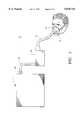
- FIG. 1is a view schematically illustrating a PAP system incorporating the pressure sensitive valve of the present invention
- FIG. 2is a perspective view of the pressure sensitive valve
- FIG. 3is a side view of the pressure sensitive valve
- FIG. 5is an end view of the valve body as shown in the direction of line 5--5 in FIG. 3;
- FIG. 6is an exploded side view of the valve
- FIG. 8is a cross-sectional side view of FIG. 4 as seen from line 8--8 of that figure illustrating the position of the disc in the presence of positive pressure;
- FIG. 9is a close-up view illustrating details of the disc.
- FIG. 1a schematic drawing of a PAP system 10 is shown in FIG. 1 which includes a flow generator 12 which delivers gas flow via a delivery conduit 14 to a patient interface 16 such as a mask.
- a humidifier 18is disposed in line with the delivery conduit 14 between the flow generator 12 and the patient interface 16.
- the patient interface 16may include an inlet 19 for the administration of a therapeutic gas such as O 2 .
- a pressure sensitive flow control valve 20is located at the outlet of the flow generator 12 at the end of the delivery conduit 14 opposite the patient interface 16.
- valve 20includes a valve body 22, valve top cap 24, a valve bottom cap 26, a spring 28 and a valve stem/disc 30/32 as shown in FIG. 3.
- the valve body 22, as seen in FIG. 6,is generally cylindrical in shape and has a top end 38 for attachment to the valve top cap 24 and a bottom end 40 for attachment to the valve bottom cap 26.
- Exhaust ports 42extend radially from an internal conical chamber 44 to the outer surface of the cylindrical body 22. In the preferred embodiment three exhaust ports 42 are shown.
- Internal conical chamber 44(FIGS. 5, 7 and 8) extends from the top end to the bottom end and has a central cylindrical guide 48 concentrically disposed within the internal conical chamber 44.
- the top end 50 of the central cylindrical guide 48is closed and the bottom end 52 preferably is open such that a spiral spring 28 is insertable inside.
- the central cylindrical guide 48preferably has three slits 54 (FIG. 5) which serve as guides for protrusions 56 on the valve stem/disc 30/32.
- the body 22also preferably has horizontal ribs 58 on the outside of the body 22 to make it difficult to block the exhaust ports 42 with tape by an untrained user.
- the valve stem/disc 30/32has a stem portion which is adapted to fit inside the cylindrical guide 48 of the valve body 22. An end of the stem portion engages the spring 28 within the cylindrical guide 48, protrusions 56 on the valve stem portion project through the slits 54 in the central cylindrical guide 48 to guide the valve stem as it moves relative to the central cylindrical guide 48.
- the protrusions 56are preferably in the form of two rows of fingers but may also be rib-like.
- valve stem portionIntegral with the valve stem portion is a valve disc portion located on an end opposite to the spring engaging end.
- the discpreferably has a centralized conical portion 59 and aerodynamic curves 60 (FIG. 9) to reduce flow resistance.
- pressurized air from the PAP unit 10enters the valve 20 through the valve bottom cap 26 and engages the disc against the work of the spring 28 (FIG. 8).
- the centralized conical portion and aerodynamic curves of the diskreduce flow resistance such that the pressurized air flows across the disc, around the outside of the internal conical chamber 44 and out through the valve top cap 24 which is connected to the delivery conduit 14 for delivery of the air to the patient through the patient interface 16.
- the valve 20also allows reverse flow into the positive airway pressure device.
- the spring 28pushes the disc against the annular flared portion 36 of the valve bottom cap 26 to seal off the entry of air or any contaminants into the PAP unit 10. Air or contaminants which enter into the valve 20 when positive air pressure is lost, enter through the valve top cap 24, flow around the outside of the internal conical chamber 44, into the inside of the internal conical chamber 44 to exit the exhaust ports 42 which are open to atmosphere.
Landscapes
- Health & Medical Sciences (AREA)
- Pulmonology (AREA)
- General Health & Medical Sciences (AREA)
- Life Sciences & Earth Sciences (AREA)
- Anesthesiology (AREA)
- Biomedical Technology (AREA)
- Heart & Thoracic Surgery (AREA)
- Hematology (AREA)
- Engineering & Computer Science (AREA)
- Animal Behavior & Ethology (AREA)
- Emergency Medicine (AREA)
- Public Health (AREA)
- Veterinary Medicine (AREA)
- Business, Economics & Management (AREA)
- Emergency Management (AREA)
- Safety Valves (AREA)
Abstract
Description
Claims (25)
Priority Applications (3)
| Application Number | Priority Date | Filing Date | Title |
|---|---|---|---|
| US08/710,682US5878743A (en) | 1996-09-23 | 1996-09-23 | Pressure sensitive flow control valve |
| PCT/US1997/016632WO1998011930A1 (en) | 1996-09-23 | 1997-09-18 | Pressure sensitive flow control valve |
| EP97941700AEP0934090A4 (en) | 1996-09-23 | 1997-09-18 | Pressure sensitive flow control valve |
Applications Claiming Priority (1)
| Application Number | Priority Date | Filing Date | Title |
|---|---|---|---|
| US08/710,682US5878743A (en) | 1996-09-23 | 1996-09-23 | Pressure sensitive flow control valve |
Publications (1)
| Publication Number | Publication Date |
|---|---|
| US5878743Atrue US5878743A (en) | 1999-03-09 |
Family
ID=24855075
Family Applications (1)
| Application Number | Title | Priority Date | Filing Date |
|---|---|---|---|
| US08/710,682Expired - LifetimeUS5878743A (en) | 1996-09-23 | 1996-09-23 | Pressure sensitive flow control valve |
Country Status (3)
| Country | Link |
|---|---|
| US (1) | US5878743A (en) |
| EP (1) | EP0934090A4 (en) |
| WO (1) | WO1998011930A1 (en) |
Cited By (55)
| Publication number | Priority date | Publication date | Assignee | Title |
|---|---|---|---|---|
| US6189532B1 (en)* | 1996-12-16 | 2001-02-20 | Resmed Limited | Valve for use in a gas delivery system |
| WO2002005884A2 (en) | 2000-07-19 | 2002-01-24 | University Of Florida | Method for treating chronic obstructive pulmonary disorder |
| US6343603B1 (en)* | 1998-10-09 | 2002-02-05 | Fisher & Paykel Limited | Connector |
| US20020023649A1 (en)* | 1999-02-09 | 2002-02-28 | Resmed Limited | Gas delivery connection assembly |
| US6371117B1 (en)* | 1998-06-15 | 2002-04-16 | Siemens Elema Ab | Directional valve |
| WO2002096342A3 (en)* | 2001-05-25 | 2003-03-06 | Respironics Inc | Exhaust port assembly for a pressure support system |
| US20030140925A1 (en)* | 2000-07-19 | 2003-07-31 | Sapienza Christine A. | System for conditioning expiratory muscles for an improved respiratory system |
| US6655382B1 (en) | 1997-09-18 | 2003-12-02 | The United States Of America As Represented By The Secretary Of Health And Human Services | Spontaneous breathing apparatus and method |
| US6739338B2 (en) | 2000-04-05 | 2004-05-25 | Deroyal Industries, Inc. | Neo-natal oxygen delivery system |
| US6766800B2 (en) | 2002-08-30 | 2004-07-27 | Sensormedics Corporation | Pressure regulating valve for use in continuous positive airway pressure devices |
| US20040173215A1 (en)* | 2003-03-07 | 2004-09-09 | 3M Innovative Properties Company | Respiratory system and method of use |
| US6792947B1 (en) | 2000-08-25 | 2004-09-21 | O-Two Systems International Inc. | Flow control valve for manual resuscitator devices |
| US20070157928A1 (en)* | 2005-09-27 | 2007-07-12 | Ric Investments, Llc | Humidifier with back-flow prevention valve |
| US20080015686A1 (en)* | 2006-07-17 | 2008-01-17 | Gale David C | Controlled degradation of stents |
| US20080257358A1 (en)* | 2007-04-23 | 2008-10-23 | Goodhealth, Llc | Passive Treatment Device |
| US20090032022A1 (en)* | 2007-07-31 | 2009-02-05 | Peter Chi Fai Ho | Pressure Reducing Valve With Flexible Cuff |
| US20110065374A1 (en)* | 2009-09-15 | 2011-03-17 | Ron Baihelfer | Grille Cover and Contaminant Level Indicator |
| US8251876B2 (en) | 2008-04-22 | 2012-08-28 | Hill-Rom Services, Inc. | Breathing exercise apparatus |
| US8251066B1 (en) | 2004-12-22 | 2012-08-28 | Ric Investments, Llc | Exhalation port with built-in entrainment valve |
| US8327848B2 (en) | 2006-09-28 | 2012-12-11 | Ric Investments, Llc | Pressure reducing valve |
| US8701662B2 (en) | 2005-09-27 | 2014-04-22 | Ric Investments, Llc | Humidifier with back-flow prevention valve |
| US20140109907A1 (en)* | 2008-02-01 | 2014-04-24 | Rajiv Doshi | Cpap interface and backup devices |
| US20140116432A1 (en)* | 2012-10-25 | 2014-05-01 | Drager Medical Gmbh | Elbow for a respiration mask |
| US9072860B2 (en) | 2003-06-20 | 2015-07-07 | Resmed Limited | Breathable gas apparatus with humidifier |
| US9180271B2 (en) | 2012-03-05 | 2015-11-10 | Hill-Rom Services Pte. Ltd. | Respiratory therapy device having standard and oscillatory PEP with nebulizer |
| US9272116B2 (en) | 1999-08-05 | 2016-03-01 | Resmed R&D Germany Gmbh | Apparatus for humidifying a respiratory gas |
| US9833354B2 (en) | 2004-12-08 | 2017-12-05 | Theravent, Inc. | Nasal respiratory devices |
| US9861774B2 (en) | 2009-08-11 | 2018-01-09 | Resmed Motor Technologies Inc. | Single stage, axial symmetric blower and portable ventilator |
| USD823455S1 (en) | 2017-02-23 | 2018-07-17 | Fisher & Paykel Healthcare Limited | Cushion assembly for breathing mask assembly |
| USD823454S1 (en) | 2017-02-23 | 2018-07-17 | Fisher & Paykel Healthcare Limited | Cushion assembly for breathing mask assembly |
| USD824020S1 (en) | 2017-02-23 | 2018-07-24 | Fisher & Paykel Healthcare Limited | Cushion assembly for breathing mask assembly |
| US20190030266A1 (en)* | 2016-02-04 | 2019-01-31 | Ip Med, Inc. | Medicament delivery device and method |
| US10220171B2 (en) | 2011-04-15 | 2019-03-05 | Fisher & Paykel Healthcare Limited | Interface comprising a rolling nasal bridge portion |
| US10293125B2 (en) | 2003-06-20 | 2019-05-21 | Resmed Limited | Flow generator with patient reminder |
| US10518054B2 (en) | 2014-08-25 | 2019-12-31 | Fisher & Paykel Healthcare Limited | Respiratory mask and related portions, components or sub-assemblies |
| US10603456B2 (en) | 2011-04-15 | 2020-03-31 | Fisher & Paykel Healthcare Limited | Interface comprising a nasal sealing portion |
| US10610228B2 (en) | 2004-12-08 | 2020-04-07 | Theravent, Inc. | Passive nasal peep devices |
| USD882066S1 (en) | 2016-05-13 | 2020-04-21 | Fisher & Paykel Healthcare Limited | Frame for a breathing mask |
| USD899598S1 (en) | 2018-09-04 | 2020-10-20 | 3B Medical, Inc. | CPAP device |
| US10905837B2 (en) | 2015-04-02 | 2021-02-02 | Hill-Rom Services Pte. Ltd. | Respiratory therapy cycle control and feedback |
| US10946155B2 (en) | 2012-09-04 | 2021-03-16 | Fisher & Paykel Healthcare Limited | Valsalva mask |
| US11007342B1 (en)* | 2020-05-29 | 2021-05-18 | Legacy US Inc. | Fluid mixing apparatus such as a ventilator |
| CN113038984A (en)* | 2018-11-16 | 2021-06-25 | 皇家飞利浦有限公司 | Valve for pressure support system |
| US11207486B2 (en) | 2020-05-29 | 2021-12-28 | Legacy US Inc. | Fluid mixing apparatus such as a ventilator |
| US11247008B1 (en) | 2020-08-05 | 2022-02-15 | Effortless Oxygen, Llc | Flow triggered gas delivery |
| US11278700B2 (en) | 2015-06-24 | 2022-03-22 | Fisher & Paykel Healthcare Limited | Breathing assistance apparatus |
| US11318276B2 (en) | 2020-08-05 | 2022-05-03 | Effortless Oxygen, Llc | Flow triggered gas delivery |
| US11318272B2 (en) | 2020-05-29 | 2022-05-03 | Legacy US Inc. | Selective attachment device with multiple fluid sources for maintaining positive fluid pressure |
| US11401974B2 (en) | 2017-04-23 | 2022-08-02 | Fisher & Paykel Healthcare Limited | Breathing assistance apparatus |
| US11420007B2 (en) | 2020-08-05 | 2022-08-23 | Effortless Oxygen, Llc | Flow triggered gas delivery |
| US11534565B2 (en) | 2012-12-18 | 2022-12-27 | Fisher & Paykel Healthcare Limited | Impeller and motor assembly |
| US11571536B2 (en) | 2011-07-13 | 2023-02-07 | Fisher & Paykel Healthcare Limited | Impeller and motor assembly |
| WO2023059797A1 (en)* | 2021-10-06 | 2023-04-13 | Sleepres, Llc | Positive airway pressure systems and methods for delivering air to a patient |
| US12017005B2 (en) | 2015-03-04 | 2024-06-25 | Fisher & Paykel Healthcare Limited | Mask system headgear |
| US12285564B2 (en) | 2014-07-18 | 2025-04-29 | Fisher & Paykel Healthcare Limited | Headgear clip arrangement |
Families Citing this family (28)
| Publication number | Priority date | Publication date | Assignee | Title |
|---|---|---|---|---|
| AUPO126596A0 (en) | 1996-07-26 | 1996-08-22 | Resmed Limited | A nasal mask and mask cushion therefor |
| US6513526B2 (en) | 1996-07-26 | 2003-02-04 | Resmed Limited | Full-face mask and mask cushion therefor |
| AUPO301796A0 (en) | 1996-10-16 | 1996-11-07 | Resmed Limited | A vent valve apparatus |
| AUPQ104099A0 (en) | 1999-06-18 | 1999-07-08 | Resmed Limited | Forehead support for facial mask |
| AUPO504597A0 (en) | 1997-02-10 | 1997-03-06 | Resmed Limited | A mask and a vent assembly therefor |
| US6561191B1 (en) | 1997-02-10 | 2003-05-13 | Resmed Limited | Mask and a vent assembly therefor |
| US6119693A (en) | 1998-01-16 | 2000-09-19 | Resmed Limited | Forehead support for facial mask |
| AUPP949999A0 (en) | 1999-03-29 | 1999-04-22 | Resmed Limited | Forehead support for facial mask II |
| DE20017940U1 (en) | 2000-10-19 | 2000-12-28 | MAP Medizintechnik für Arzt und Patient GmbH & Co KG, 82152 Planegg | Breathing mask for supplying a breathing gas to a mask user and a derivation device for deriving breathing gas |
| DE10201682A1 (en) | 2002-01-17 | 2003-07-31 | Map Medizin Technologie Gmbh | The breathing mask arrangement |
| DE10151984C5 (en) | 2001-10-22 | 2008-07-17 | Map Medizin-Technologie Gmbh | Application device for a breathing mask arrangement |
| US7320323B2 (en) | 2001-10-22 | 2008-01-22 | Map Medizin-Technologie Gmbh | Breathing mask device and application device and frontal support device thereof |
| USD507831S1 (en) | 2002-03-22 | 2005-07-26 | Invacare Corporation | Nasal mask |
| USD583931S1 (en) | 2002-03-22 | 2008-12-30 | Invacare Corporation | Nasal mask |
| EP2345446B1 (en) | 2002-03-22 | 2015-12-16 | Invacare Corporation | Nasal mask |
| ES2443417T3 (en) | 2002-09-06 | 2014-02-19 | Resmed Limited | Forehead pad for a respiratory mask |
| WO2004052438A1 (en) | 2002-12-06 | 2004-06-24 | Fisher & Paykel Healthcare Limited | Mouthpiece |
| US7621274B2 (en) | 2003-03-22 | 2009-11-24 | Invacare Corporation | Nasal mask |
| US7503327B2 (en) | 2003-04-10 | 2009-03-17 | Resmed Limited | Mask with integral cushion and forehead piece |
| CN101987221B (en) | 2003-05-02 | 2013-09-04 | 雷斯梅德有限公司 | A mask system |
| ATE538832T1 (en) | 2003-05-05 | 2012-01-15 | Resmed Ltd | HEADPROOF FOR A FACE MASK |
| CN101683545B (en) | 2004-04-09 | 2012-11-28 | 雷斯梅德有限公司 | Nasal assembly and nasal face mask with the nasal assembly |
| NZ608551A (en) | 2004-06-16 | 2014-10-31 | Resmed Ltd | Cushion for a respiratory mask assembly |
| US8397728B2 (en) | 2005-10-14 | 2013-03-19 | Resmed Limited | Cushion to frame assembly mechanism |
| US20090126739A1 (en) | 2005-10-25 | 2009-05-21 | Resmed Limited | Interchangeable Mask Assembly |
| US8517023B2 (en) | 2007-01-30 | 2013-08-27 | Resmed Limited | Mask system with interchangeable headgear connectors |
| US11331447B2 (en) | 2008-03-04 | 2022-05-17 | ResMed Pty Ltd | Mask system with snap-fit shroud |
| NZ783425A (en) | 2008-03-04 | 2022-12-23 | ResMed Pty Ltd | Mask system |
Citations (15)
| Publication number | Priority date | Publication date | Assignee | Title |
|---|---|---|---|---|
| FR1204930A (en)* | 1957-10-16 | 1960-01-28 | Resuscitation device | |
| US3643686A (en)* | 1970-10-21 | 1972-02-22 | Ewald Koegel | High-velocity breathing valve |
| US3662774A (en)* | 1969-09-09 | 1972-05-16 | Aga Ab | Gas evacuator for breathing apparatus |
| US4229832A (en)* | 1979-05-21 | 1980-10-28 | The United States Of America As Represented By The Secretary Of The Navy | Diver's suit excess gas exhaust valve |
| US4579114A (en)* | 1983-10-11 | 1986-04-01 | Wisdom Corporation | Mouth to mouth resuscitation device |
| US4870963A (en)* | 1988-05-06 | 1989-10-03 | Carol Bussell | Respiratory aid device |
| US4873970A (en)* | 1986-04-22 | 1989-10-17 | Auergesellschaft Gmbh | Warning device to indicate the state of gases exhaustion of a gas filter retaining dangerous gases |
| US5109840A (en)* | 1991-02-14 | 1992-05-05 | Specialty Packaging Licensing Company | Resuscitator having directional control valve with internal "PEEP" adjustment valve |
| US5370356A (en)* | 1990-12-25 | 1994-12-06 | Pesovic; Predrag L. J. | One-way fluid flow non-return valve |
| US5398673A (en)* | 1993-12-10 | 1995-03-21 | Environmental Support Systems, Inc. | Resuscitator-snorkel for land or water use |
| US5398714A (en)* | 1990-03-06 | 1995-03-21 | Price; William E. | Resuscitation and inhalation device |
| US5469842A (en)* | 1994-07-11 | 1995-11-28 | Flynn; Stephen | CPR face mask |
| US5562093A (en)* | 1995-09-06 | 1996-10-08 | Gerson; Howard J. | Mouth-to-mouth resuscitation barrier |
| US5592933A (en)* | 1992-07-22 | 1997-01-14 | Mallinckrodt Medical, Inc. | Hygroscopic cartridge particularly for filters for medical use |
| US5598839A (en)* | 1994-04-20 | 1997-02-04 | Diemolding Corporation | Positive expiratory pressure device |
Family Cites Families (5)
| Publication number | Priority date | Publication date | Assignee | Title |
|---|---|---|---|---|
| FR1310608A (en)* | 1961-10-16 | 1962-11-30 | Robert & Carriere Lab | Respiratory valve for anesthesia or resuscitation device operating in open circuit |
| FR1449918A (en)* | 1965-07-06 | 1966-08-19 | Non-return valve for administration of oxygen or anesthetic gases by inhalation or by controlled or assisted breathing | |
| GB1192379A (en)* | 1966-11-28 | 1970-05-20 | Geoffrey Barnet Burchell | A Valve Device |
| FR1552128A (en)* | 1967-11-20 | 1969-01-03 | ||
| US5301667A (en)* | 1992-08-03 | 1994-04-12 | Vital Signs, Inc. | Pressure limiting valve for ventilation breathing bag apparatus |
- 1996
- 1996-09-23USUS08/710,682patent/US5878743A/ennot_activeExpired - Lifetime
- 1997
- 1997-09-18WOPCT/US1997/016632patent/WO1998011930A1/ennot_activeApplication Discontinuation
- 1997-09-18EPEP97941700Apatent/EP0934090A4/ennot_activeWithdrawn
Patent Citations (15)
| Publication number | Priority date | Publication date | Assignee | Title |
|---|---|---|---|---|
| FR1204930A (en)* | 1957-10-16 | 1960-01-28 | Resuscitation device | |
| US3662774A (en)* | 1969-09-09 | 1972-05-16 | Aga Ab | Gas evacuator for breathing apparatus |
| US3643686A (en)* | 1970-10-21 | 1972-02-22 | Ewald Koegel | High-velocity breathing valve |
| US4229832A (en)* | 1979-05-21 | 1980-10-28 | The United States Of America As Represented By The Secretary Of The Navy | Diver's suit excess gas exhaust valve |
| US4579114A (en)* | 1983-10-11 | 1986-04-01 | Wisdom Corporation | Mouth to mouth resuscitation device |
| US4873970A (en)* | 1986-04-22 | 1989-10-17 | Auergesellschaft Gmbh | Warning device to indicate the state of gases exhaustion of a gas filter retaining dangerous gases |
| US4870963A (en)* | 1988-05-06 | 1989-10-03 | Carol Bussell | Respiratory aid device |
| US5398714A (en)* | 1990-03-06 | 1995-03-21 | Price; William E. | Resuscitation and inhalation device |
| US5370356A (en)* | 1990-12-25 | 1994-12-06 | Pesovic; Predrag L. J. | One-way fluid flow non-return valve |
| US5109840A (en)* | 1991-02-14 | 1992-05-05 | Specialty Packaging Licensing Company | Resuscitator having directional control valve with internal "PEEP" adjustment valve |
| US5592933A (en)* | 1992-07-22 | 1997-01-14 | Mallinckrodt Medical, Inc. | Hygroscopic cartridge particularly for filters for medical use |
| US5398673A (en)* | 1993-12-10 | 1995-03-21 | Environmental Support Systems, Inc. | Resuscitator-snorkel for land or water use |
| US5598839A (en)* | 1994-04-20 | 1997-02-04 | Diemolding Corporation | Positive expiratory pressure device |
| US5469842A (en)* | 1994-07-11 | 1995-11-28 | Flynn; Stephen | CPR face mask |
| US5562093A (en)* | 1995-09-06 | 1996-10-08 | Gerson; Howard J. | Mouth-to-mouth resuscitation barrier |
Cited By (112)
| Publication number | Priority date | Publication date | Assignee | Title |
|---|---|---|---|---|
| US6189532B1 (en)* | 1996-12-16 | 2001-02-20 | Resmed Limited | Valve for use in a gas delivery system |
| US6655382B1 (en) | 1997-09-18 | 2003-12-02 | The United States Of America As Represented By The Secretary Of Health And Human Services | Spontaneous breathing apparatus and method |
| US6371117B1 (en)* | 1998-06-15 | 2002-04-16 | Siemens Elema Ab | Directional valve |
| US6343603B1 (en)* | 1998-10-09 | 2002-02-05 | Fisher & Paykel Limited | Connector |
| US20060076017A1 (en)* | 1999-02-09 | 2006-04-13 | Resmed Limited | Mask with anti-asphyxia valve |
| US20020023649A1 (en)* | 1999-02-09 | 2002-02-28 | Resmed Limited | Gas delivery connection assembly |
| US7174893B2 (en)* | 1999-02-09 | 2007-02-13 | Resmed Limited | Mask with anti-asphyxia valve |
| US7185652B2 (en) | 1999-02-09 | 2007-03-06 | Resmed Limited | Gas delivery connection assembly |
| US9555211B2 (en) | 1999-08-05 | 2017-01-31 | Resmed R&D Germany Gmbh | Apparatus for humidifying a respiratory gas |
| US10052450B2 (en) | 1999-08-05 | 2018-08-21 | Resmed R&D Germany Gmbh | Apparatus for humidifying a respiratory gas |
| US9302067B2 (en) | 1999-08-05 | 2016-04-05 | Resmed R&D Germany Gmbh | Apparatus for humidifying a respiratory gas |
| US9545494B2 (en) | 1999-08-05 | 2017-01-17 | Resmed R&D Germany Gmbh | Apparatus for humidifying a respiratory gas |
| US9884163B2 (en) | 1999-08-05 | 2018-02-06 | RedMed R&D Germany GmbH | Apparatus for humidifying a respiratory gas |
| US9545493B2 (en) | 1999-08-05 | 2017-01-17 | Resmed R&D Germany Gmbh | Apparatus for humidifying a respiratory gas |
| US9272116B2 (en) | 1999-08-05 | 2016-03-01 | Resmed R&D Germany Gmbh | Apparatus for humidifying a respiratory gas |
| US6739338B2 (en) | 2000-04-05 | 2004-05-25 | Deroyal Industries, Inc. | Neo-natal oxygen delivery system |
| US20030140925A1 (en)* | 2000-07-19 | 2003-07-31 | Sapienza Christine A. | System for conditioning expiratory muscles for an improved respiratory system |
| WO2002005884A2 (en) | 2000-07-19 | 2002-01-24 | University Of Florida | Method for treating chronic obstructive pulmonary disorder |
| US6568387B2 (en) | 2000-07-19 | 2003-05-27 | University Of Florida | Method for treating chronic obstructive pulmonary disorder |
| US6792947B1 (en) | 2000-08-25 | 2004-09-21 | O-Two Systems International Inc. | Flow control valve for manual resuscitator devices |
| US8061355B2 (en) | 2001-05-25 | 2011-11-22 | Ric Investments, Llc. | Exhaust port assembly for a pressure support system |
| US20050126573A1 (en)* | 2001-05-25 | 2005-06-16 | Respironics, Inc. | Exhaust port assembly for a pressure support system |
| US6851425B2 (en) | 2001-05-25 | 2005-02-08 | Respironics, Inc. | Exhaust port assembly for a pressure support system |
| AU2002310048B2 (en)* | 2001-05-25 | 2006-08-10 | Respironics, Inc. | Exhaust port assembly for a pressure support system |
| WO2002096342A3 (en)* | 2001-05-25 | 2003-03-06 | Respironics Inc | Exhaust port assembly for a pressure support system |
| US7568482B2 (en) | 2001-05-25 | 2009-08-04 | Ric Investments, Llc | Exhaust port assembly for a pressure support system |
| US20090272380A1 (en)* | 2001-05-25 | 2009-11-05 | Koninklijke Philips Electronics, N.V. | Exhaust port assembly for a pressure support system |
| US6766800B2 (en) | 2002-08-30 | 2004-07-27 | Sensormedics Corporation | Pressure regulating valve for use in continuous positive airway pressure devices |
| WO2004080537A1 (en)* | 2003-03-07 | 2004-09-23 | 3M Innovative Properties Company | Respiratory system and method of use |
| US20040173215A1 (en)* | 2003-03-07 | 2004-09-09 | 3M Innovative Properties Company | Respiratory system and method of use |
| US7328700B2 (en) | 2003-03-07 | 2008-02-12 | 3M Innovative Properties | Respiratory system and method of use |
| US11260187B2 (en) | 2003-06-20 | 2022-03-01 | ResMed Pty Ltd | Breathable gas supply apparatus |
| US10201676B2 (en) | 2003-06-20 | 2019-02-12 | Resmed Limited | Breathable gas supply apparatus |
| USRE46543E1 (en) | 2003-06-20 | 2017-09-12 | Resmed Limited | Breathable gas apparatus with humidifier |
| US9610420B2 (en) | 2003-06-20 | 2017-04-04 | Resmed Limited | Breathable gas apparatus with humidifier |
| US9072860B2 (en) | 2003-06-20 | 2015-07-07 | Resmed Limited | Breathable gas apparatus with humidifier |
| US10293125B2 (en) | 2003-06-20 | 2019-05-21 | Resmed Limited | Flow generator with patient reminder |
| US10850053B2 (en) | 2003-06-20 | 2020-12-01 | ResMed Pty Ltd | Breathable gas supply apparatus |
| US9358359B2 (en) | 2003-06-20 | 2016-06-07 | Resmed Limited | Breathable gas apparatus with humidifier |
| US11413412B2 (en) | 2003-06-20 | 2022-08-16 | ResMed Pty Ltd | Breathable gas supply apparatus |
| US9833354B2 (en) | 2004-12-08 | 2017-12-05 | Theravent, Inc. | Nasal respiratory devices |
| US10610228B2 (en) | 2004-12-08 | 2020-04-07 | Theravent, Inc. | Passive nasal peep devices |
| US8251066B1 (en) | 2004-12-22 | 2012-08-28 | Ric Investments, Llc | Exhalation port with built-in entrainment valve |
| US20070157928A1 (en)* | 2005-09-27 | 2007-07-12 | Ric Investments, Llc | Humidifier with back-flow prevention valve |
| US8701662B2 (en) | 2005-09-27 | 2014-04-22 | Ric Investments, Llc | Humidifier with back-flow prevention valve |
| US8997740B2 (en) | 2005-09-27 | 2015-04-07 | Ric Investments, Llc | Humidifier with back-flow prevention valve |
| US9713692B2 (en) | 2005-09-27 | 2017-07-25 | Ric Investments, Llc | Humidifier with back-flow prevention valve |
| US20080015686A1 (en)* | 2006-07-17 | 2008-01-17 | Gale David C | Controlled degradation of stents |
| US8327848B2 (en) | 2006-09-28 | 2012-12-11 | Ric Investments, Llc | Pressure reducing valve |
| US20080257358A1 (en)* | 2007-04-23 | 2008-10-23 | Goodhealth, Llc | Passive Treatment Device |
| US20090032022A1 (en)* | 2007-07-31 | 2009-02-05 | Peter Chi Fai Ho | Pressure Reducing Valve With Flexible Cuff |
| US8365731B2 (en) | 2007-07-31 | 2013-02-05 | Ric Investments, Llc | Pressure reducing valve with flexible cuff |
| US20140109907A1 (en)* | 2008-02-01 | 2014-04-24 | Rajiv Doshi | Cpap interface and backup devices |
| US8251876B2 (en) | 2008-04-22 | 2012-08-28 | Hill-Rom Services, Inc. | Breathing exercise apparatus |
| US9861774B2 (en) | 2009-08-11 | 2018-01-09 | Resmed Motor Technologies Inc. | Single stage, axial symmetric blower and portable ventilator |
| US10874810B2 (en) | 2009-08-11 | 2020-12-29 | Resmed Motor Technologies Inc. | Single stage, axial symmetric blower and portable ventilator |
| US11998690B2 (en) | 2009-08-11 | 2024-06-04 | Resmed Motor Technologies Inc. | Single stage, axial symmetric blower and portable ventilator |
| US20110065374A1 (en)* | 2009-09-15 | 2011-03-17 | Ron Baihelfer | Grille Cover and Contaminant Level Indicator |
| US10842955B2 (en) | 2011-04-15 | 2020-11-24 | Fisher & Paykel Healthcare Limited | Interface comprising a rolling nasal bridge portion |
| US10835697B2 (en) | 2011-04-15 | 2020-11-17 | Fisher & Paykel Healthcare Limited | Interface comprising a rolling nasal bridge portion |
| US11065406B2 (en) | 2011-04-15 | 2021-07-20 | Fisher & Paykel Healthcare Limited | Interface comprising a rolling nasal bridge portion |
| US11883591B2 (en) | 2011-04-15 | 2024-01-30 | Fisher & Paykel Healthcare Limited | Interface comprising a rolling nasal bridge portion |
| US10603456B2 (en) | 2011-04-15 | 2020-03-31 | Fisher & Paykel Healthcare Limited | Interface comprising a nasal sealing portion |
| US12390609B2 (en) | 2011-04-15 | 2025-08-19 | Fisher & Paykel Healthcare Limited | Interface comprising a nasal sealing portion |
| US10220171B2 (en) | 2011-04-15 | 2019-03-05 | Fisher & Paykel Healthcare Limited | Interface comprising a rolling nasal bridge portion |
| US11559647B2 (en) | 2011-04-15 | 2023-01-24 | Fisher & Paykel Healthcare Limited | Interface comprising a nasal sealing portion |
| US10828443B2 (en) | 2011-04-15 | 2020-11-10 | Fisher & Paykel Healthcare Limited | Interface comprising a rolling nasal bridge portion |
| US10828442B2 (en) | 2011-04-15 | 2020-11-10 | Fisher & Paykel Healthcare Limited | Interface comprising a rolling nasal bridge portion |
| US10828440B2 (en) | 2011-04-15 | 2020-11-10 | Fisher & Paykle Healthcare Limited | Interface comprising a rolling nasal bridge portion |
| US10828441B2 (en) | 2011-04-15 | 2020-11-10 | Fisher & Paykel Healthcare Limited | Interface comprising a rolling nasal bridge portion |
| US11571536B2 (en) | 2011-07-13 | 2023-02-07 | Fisher & Paykel Healthcare Limited | Impeller and motor assembly |
| US12318538B2 (en) | 2011-07-13 | 2025-06-03 | Fisher & Paykel Healthcare Limited | Impeller and motor assembly |
| US9180271B2 (en) | 2012-03-05 | 2015-11-10 | Hill-Rom Services Pte. Ltd. | Respiratory therapy device having standard and oscillatory PEP with nebulizer |
| US10946155B2 (en) | 2012-09-04 | 2021-03-16 | Fisher & Paykel Healthcare Limited | Valsalva mask |
| US11065412B2 (en) | 2012-09-04 | 2021-07-20 | Fisher & Paykel Healthcare Limited | Valsalva mask |
| US20140116432A1 (en)* | 2012-10-25 | 2014-05-01 | Drager Medical Gmbh | Elbow for a respiration mask |
| US9731091B2 (en)* | 2012-10-25 | 2017-08-15 | Draegerwerk Ag & Co. Kgaa | Elbow for a respiration mask |
| US11534565B2 (en) | 2012-12-18 | 2022-12-27 | Fisher & Paykel Healthcare Limited | Impeller and motor assembly |
| US11992613B2 (en) | 2012-12-18 | 2024-05-28 | Fisher & Paykel Healthcare Limited | Impeller and motor assembly |
| US12285564B2 (en) | 2014-07-18 | 2025-04-29 | Fisher & Paykel Healthcare Limited | Headgear clip arrangement |
| US11305084B2 (en) | 2014-08-25 | 2022-04-19 | Fisher & Paykel Healthcare Limited | Respiratory mask and related portions, components or sub-assemblies |
| US10518054B2 (en) | 2014-08-25 | 2019-12-31 | Fisher & Paykel Healthcare Limited | Respiratory mask and related portions, components or sub-assemblies |
| US12017005B2 (en) | 2015-03-04 | 2024-06-25 | Fisher & Paykel Healthcare Limited | Mask system headgear |
| US10905836B2 (en) | 2015-04-02 | 2021-02-02 | Hill-Rom Services Pte. Ltd. | Manifold for respiratory device |
| US11992611B2 (en) | 2015-04-02 | 2024-05-28 | Hill-Rom Services Pte. Ltd. | Respiratory therapy apparatus control |
| US10905837B2 (en) | 2015-04-02 | 2021-02-02 | Hill-Rom Services Pte. Ltd. | Respiratory therapy cycle control and feedback |
| US11278700B2 (en) | 2015-06-24 | 2022-03-22 | Fisher & Paykel Healthcare Limited | Breathing assistance apparatus |
| US20190030266A1 (en)* | 2016-02-04 | 2019-01-31 | Ip Med, Inc. | Medicament delivery device and method |
| US11793950B2 (en)* | 2016-02-04 | 2023-10-24 | Propel-Air Biopharma, Llc | Medicament delivery device and method |
| USD882066S1 (en) | 2016-05-13 | 2020-04-21 | Fisher & Paykel Healthcare Limited | Frame for a breathing mask |
| USD1010103S1 (en) | 2016-05-13 | 2024-01-02 | Fisher & Paykel Healthcare Limited | Breathing mask assembly including a frame, headgear, and seal |
| USD1059584S1 (en) | 2016-05-13 | 2025-01-28 | Fisher & Paykel Healthcare Limited | Breathing mask assembly including a frame and seal |
| USD823454S1 (en) | 2017-02-23 | 2018-07-17 | Fisher & Paykel Healthcare Limited | Cushion assembly for breathing mask assembly |
| USD823455S1 (en) | 2017-02-23 | 2018-07-17 | Fisher & Paykel Healthcare Limited | Cushion assembly for breathing mask assembly |
| USD994876S1 (en) | 2017-02-23 | 2023-08-08 | Fisher & Paykel Healthcare Limited | Cushion assembly for breathing mask assembly |
| USD969306S1 (en) | 2017-02-23 | 2022-11-08 | Fisher & Paykel Healthcare Limited | Cushion assembly for breathing mask assembly |
| USD824020S1 (en) | 2017-02-23 | 2018-07-24 | Fisher & Paykel Healthcare Limited | Cushion assembly for breathing mask assembly |
| USD837973S1 (en) | 2017-02-23 | 2019-01-08 | Fisher & Paykel Healthcare Limited | Cushion assembly for breathing mask assembly |
| USD1051356S1 (en) | 2017-02-23 | 2024-11-12 | Fisher & Paykel Healthcare Limited | Cushion assembly for breathing mask assembly |
| US11401974B2 (en) | 2017-04-23 | 2022-08-02 | Fisher & Paykel Healthcare Limited | Breathing assistance apparatus |
| US12292085B2 (en) | 2017-04-23 | 2025-05-06 | Fisher & Paykel Healthare Limited | Breathing assistance apparatus |
| USD899598S1 (en) | 2018-09-04 | 2020-10-20 | 3B Medical, Inc. | CPAP device |
| CN113038984B (en)* | 2018-11-16 | 2024-07-05 | 皇家飞利浦有限公司 | Valve for pressure support system |
| US11471638B2 (en)* | 2018-11-16 | 2022-10-18 | Koninklijke Philips N.V. | Pressure support system valve |
| CN113038984A (en)* | 2018-11-16 | 2021-06-25 | 皇家飞利浦有限公司 | Valve for pressure support system |
| US11207486B2 (en) | 2020-05-29 | 2021-12-28 | Legacy US Inc. | Fluid mixing apparatus such as a ventilator |
| US11007342B1 (en)* | 2020-05-29 | 2021-05-18 | Legacy US Inc. | Fluid mixing apparatus such as a ventilator |
| US11318272B2 (en) | 2020-05-29 | 2022-05-03 | Legacy US Inc. | Selective attachment device with multiple fluid sources for maintaining positive fluid pressure |
| US11247008B1 (en) | 2020-08-05 | 2022-02-15 | Effortless Oxygen, Llc | Flow triggered gas delivery |
| US11318276B2 (en) | 2020-08-05 | 2022-05-03 | Effortless Oxygen, Llc | Flow triggered gas delivery |
| US11420007B2 (en) | 2020-08-05 | 2022-08-23 | Effortless Oxygen, Llc | Flow triggered gas delivery |
| WO2023059797A1 (en)* | 2021-10-06 | 2023-04-13 | Sleepres, Llc | Positive airway pressure systems and methods for delivering air to a patient |
Also Published As
| Publication number | Publication date |
|---|---|
| EP0934090A4 (en) | 2000-08-16 |
| EP0934090A1 (en) | 1999-08-11 |
| WO1998011930A1 (en) | 1998-03-26 |
Similar Documents
| Publication | Publication Date | Title |
|---|---|---|
| US5878743A (en) | Pressure sensitive flow control valve | |
| US4278110A (en) | Demand responsive flow controller | |
| US12011541B2 (en) | Methods and apparatus for preventing rainout | |
| US20240342410A1 (en) | Exchanger assembly for respiratory treatment | |
| US6923181B2 (en) | Nasal mask | |
| EP1077666B1 (en) | Exhalation valve for mechanical ventilator | |
| US6343603B1 (en) | Connector | |
| JP5054696B2 (en) | Backflow prevention valve additional humidifier | |
| JP5385795B2 (en) | Humidifier with backflow prevention valve | |
| US5647355A (en) | Automatic safety valve for respiratory equipment which is counter-balanced and self-adjusting | |
| JP4691528B2 (en) | Adjustable two-way valve structure for controlling fluid flow and method for adjusting critical pressure differential | |
| US8251066B1 (en) | Exhalation port with built-in entrainment valve | |
| ATE172124T1 (en) | INHALER WITH BREATHING FLOW CONTROL | |
| JP4741135B2 (en) | Valve device for supply control of pressurized fluid | |
| WO1996040336A2 (en) | Pneumatically-operated gas demand apparatus | |
| US6318366B1 (en) | Supply valve and diaphragm for a pneumatically-operated gas demand apparatus | |
| US5505198A (en) | Unidirectional airflow tracheotomy valve | |
| WO2000043060A1 (en) | Flow directing device and system for supplying breathable gas to a patient | |
| JP2994172B2 (en) | Breathing aid |
Legal Events
| Date | Code | Title | Description |
|---|---|---|---|
| AS | Assignment | Owner name:RESPIRONICS, INC., PENNSYLVANIA Free format text:ASSIGNMENT OF ASSIGNORS INTEREST;ASSIGNORS:ZDROJKOWSKI, RONALD J.;STARR, JOHN R.;MICELI, JOSEPH M.;REEL/FRAME:008192/0445 Effective date:19960923 | |
| STCF | Information on status: patent grant | Free format text:PATENTED CASE | |
| FPAY | Fee payment | Year of fee payment:4 | |
| REMI | Maintenance fee reminder mailed | ||
| AS | Assignment | Owner name:RIC INVESTMENTS, INC.,DELAWARE Free format text:DIVIDEND FROM SUBSIDIARY TO PARENT;ASSIGNOR:RESPIRONICS, INC.;REEL/FRAME:016741/0570 Effective date:20020627 Owner name:RIC INVESTMENTS, INC., DELAWARE Free format text:DIVIDEND FROM SUBSIDIARY TO PARENT;ASSIGNOR:RESPIRONICS, INC.;REEL/FRAME:016741/0570 Effective date:20020627 | |
| AS | Assignment | Owner name:RIC INVESTMENTS, LLC.,DELAWARE Free format text:CHANGE OF NAME;ASSIGNOR:RIC INVESTMENTS, INC.;REEL/FRAME:016747/0177 Effective date:20040317 Owner name:RIC INVESTMENTS, LLC., DELAWARE Free format text:CHANGE OF NAME;ASSIGNOR:RIC INVESTMENTS, INC.;REEL/FRAME:016747/0177 Effective date:20040317 | |
| FPAY | Fee payment | Year of fee payment:8 | |
| FPAY | Fee payment | Year of fee payment:12 |