US5877920A - Head suspension assembly with displacement limiter - Google Patents
Head suspension assembly with displacement limiterDownload PDFInfo
- Publication number
- US5877920A US5877920AUS08/719,527US71952796AUS5877920AUS 5877920 AUS5877920 AUS 5877920AUS 71952796 AUS71952796 AUS 71952796AUS 5877920 AUS5877920 AUS 5877920A
- Authority
- US
- United States
- Prior art keywords
- load beam
- gimbal
- suspension assembly
- back surface
- disc drive
- Prior art date
- Legal status (The legal status is an assumption and is not a legal conclusion. Google has not performed a legal analysis and makes no representation as to the accuracy of the status listed.)
- Expired - Lifetime
Links
Images


Classifications
- G—PHYSICS
- G11—INFORMATION STORAGE
- G11B—INFORMATION STORAGE BASED ON RELATIVE MOVEMENT BETWEEN RECORD CARRIER AND TRANSDUCER
- G11B5/00—Recording by magnetisation or demagnetisation of a record carrier; Reproducing by magnetic means; Record carriers therefor
- G11B5/48—Disposition or mounting of heads or head supports relative to record carriers ; arrangements of heads, e.g. for scanning the record carrier to increase the relative speed
- G11B5/4806—Disposition or mounting of heads or head supports relative to record carriers ; arrangements of heads, e.g. for scanning the record carrier to increase the relative speed specially adapted for disk drive assemblies, e.g. assembly prior to operation, hard or flexible disk drives
- G11B5/4826—Mounting, aligning or attachment of the transducer head relative to the arm assembly, e.g. slider holding members, gimbals, adhesive
Definitions
- the present inventionrelates to disc drive storage systems and, more particularly, to a head suspension assembly having a flexure displacement limiter.
- Disc drives of the "Winchester” typeare well known in the industry. Such drives use rigid discs coated with a magnetizable medium for storage of digital information in a plurality of circular, concentric data tracks.
- the discsare mounted on a spindle motor which causes the discs to spin and the surfaces of the discs to pass under respective recording heads.
- a recording headincludes a hydrodynamic (e.g. air) bearing slider and a transducer for writing information to and reading information from the disc surface.
- An actuator mechanismmoves the heads from track to track across the surfaces of the discs under control of electronic circuitry.
- the actuator mechanismincludes a track accessing arm and a head suspension assembly for each head.
- the head suspension assemblyincludes a load beam and a gimbal.
- the load beamprovides a preload force which forces the head toward the disc surface.
- the gimbalis positioned between the load beam and the slider to provide a resilient connection that allows the slider to pitch and roll while following the topography of the disc.
- the sliderincludes an air bearing surface which faces the disc surface.
- a conventional catamaran sliderincludes a pair of raised side rails which face the disc surface and form air bearing surfaces. As the disc rotates, the disc drags air under the slider along the air bearing surfaces in a direction approximately parallel to the tangential velocity of the disc.
- the preload force supplied by the load beamcounteracts the hydrodynamic lifting force.
- the preload force and the hydrodynamic lifting forcereach an equilibrium based upon the hydrodynamic properties of the slider and the speed of rotation of the disc.
- the preload forceis transferred from the load beam to the back surface of the slider through a spherical load point button, which is typically a stamped feature on the gimbal having an apex that contacts the under surface of the load beam.
- the load point buttonprovides a point about which the slider can pitch and roll and limits vertical displacement of the head and gimbal in a direction away from the disc surface.
- this structuredoes not limit vertical displacement in a direction toward the disc surface, which can cause damage to the delicate flexure features of the gimbal.
- Undesirable vertical displacementcan occur due to forces applied during assembly, fly testing or shipping and handling.
- transportation shockmay generate displacement forces large enough to yield the twisted wire electrical interconnections to the head or cause the delicate flexure features of the gimbal to bend past their yield point, which may result in separation between the load beam and the head at the load point button.
- certain disc driveshave a ramp which lifts the load beam to unload the slider from the disc surface during start and stop of disc rotation. If the slider is a self-loading slider, subambient pressure developed between the slider and the disc surface can cause a large vertical displacement of the gimbal as the slider is lifted from the disc surface. This displacement can cause damage to the gimbal flexure features.
- the head suspension assembly of the present inventionincludes a recording head, a load beam and a gimbal.
- the recording headincludes a recording surface and a back surface.
- the load beamincludes a front surface, a back surface, a distal end and a load protrusion.
- the load protrusionextends from the front surface of the load beam toward the back surface of the recording head.
- the gimbalis attached to the back surface of the load beam and includes a head mounting pad which is positioned beyond the distal end of the load beam.
- the recording headis attached to the head mounting pad.
- a first displacement limiterextends between the load beam and the gimbal, which limits vertical displacement of the gimbal in a direction toward the recording head relative to the load beam.
- the gimbalhas a mounting portion and a flexure portion.
- the flexure portionhas a cutout which forms first and second spaced flexure beams extending parallel to the longitudinal axis of the load beam and a cross member extending between the flexure beams beyond the distal end of the load beam.
- the cross memberforms the head mounting pad.
- the gimbalfurther includes a front surface and a back surface, with the front surface facing the back surface of the load beam.
- the first displacement limiterextends from the periphery of the load beam toward the first flexure beam in a direction transverse to the longitudinal axis and overlaps the first flexure beam.
- the first displacement limiterhas a vertical bend which offsets the first displacement limiter toward the recording head from a plane defined by the back surface of the load beam to provide a predetermined vertical clearance between the first displacement limiter and the first flexure beam.
- a second displacement limiterextends from the periphery of the load beam toward the second flexure beam in a direction transverse to the longitudinal axis and overlaps the second flexure beam.
- the first and second displacement limiterslimit vertical displacement of the gimbal in a direction toward the recording head relative to the load beam. The vertical displacement is limited to the clearance between the displacement limiters and the flexure beams.
- first and second displacement limitersextend from the inner periphery of the gimbal toward the load beam and overlap the load beam.
- the first and second displacement limiterscan extend from the first and second flexure beams, respectively, or from the cross member.
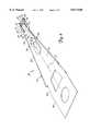
- FIG. 1is a top plan view of a disc drive data storage device in which the present invention is useful.
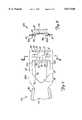
- FIG. 2is a perspective view of a head suspension assembly according to the present invention, as viewed from a back surface.
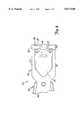
- FIG. 3is perspective view of the head suspension assembly, as viewed from a front surface.
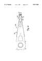
- FIG. 4is a top plan view of a distal end of a head suspension assembly having an alternative flexure structure.
- FIG. 5is a sectional view of the head suspension assembly as viewed along lines 5--5 of FIG. 4.
- FIG. 6ais a schematic, side plan view of the head suspension assembly illustrating a bond pad angle.
- FIG. 6bis a schematic, side plan view of the head suspension assembly illustrating a pitch static angle.
- FIG. 7is a top plan view of a distal end of a head suspension assembly according to an alternative embodiment of the present invention.
- FIG. 8is a sectional view of the head suspension assembly as viewed along lines 8--8 of FIG. 7.
- FIG. 9is a top plan view of a head suspension assembly having displacement limiters extending from a cross member on the gimbal.
- FIG. 10is a top plan view of a head suspension assembly having a lift tab, according to the present invention.
- FIG. 11is a top plan view of a head suspension assembly having a gimbal with an integrated flex circuit, according to the present invention.
- FIG. 1is a plan view of a typical disc drive 10.
- Disc drive 10includes a housing with a base 12 and a top cover 14 (portions of top cover 14 are removed for clarity).
- Disc drive 10further includes a disc pack 16, which is mounted on a spindle motor (not shown) by a disc clamp 18.
- Disc pack 16includes a plurality of individual discs which are mounted for co-rotation about a central axis. Each disc surface has an associated head 20 which is mounted to disc drive 10 for communication with the disc surface. Heads 20 are supported by head suspension assemblies 22 which are in turn attached to track accessing arms 24 of an actuator 26.
- Voice coil motor 28rotates actuator 26 with its attached heads 20 about a pivot shaft 30 to position heads 20 over a desired data track along an arcuate path 32 under the control of electronic circuitry 33.
- FIG. 2is a perspective view of a head suspension assembly 22, as viewed from a back surface 34.
- Head suspension assembly 22includes load beam 40 and gimbal 44.
- Load beam 40includes mounting portion 46, flexible beam portion 48, rigid beam portion 50 and longitudinal axis 51.
- Mounting portion 46is mounted to track accessing arm 24 (shown in FIG. 1).
- Flexible beam portion 48supplies a preload force to determine the flying height of head 20.
- Rigid beam portion 50transfers the preload force from flexible beam portion 48 to head 20.
- Gimbal 44is attached to back surface 34 of load beam 40.
- Gimbal 44includes rearward mounting portion 52 and forward flexure portion 54.
- Mounting portion 52has alignment features 56 which mate with corresponding alignment features in load beam 40 when gimbal 44 is attached to load beam 40.
- Gimbal 44can be attached to load beam 40 in a variety of ways, such as by welding or with an adhesive.
- Flexure portion 54includes a cutout 58 which forms flexure beams 60 and 62, cross member 64 and tongue 65. Flexure beams 60 and 62 are generally parallel to longitudinal axis 51 of load beam 40. Tongue 65 is welded to load beam 40 to provide additional stiffness to the load beam's distal end.
- the features of gimbal 44are photo-etched from stainless steel stock. Through-etching is accomplished using matching masking patterns on both sides of the material. When the material thus masked is exposed to the etchant, the exposed material is etched from both surfaces until it is completely etched away.
- Cross member 64includes head mounting pad 66 and bends 68 and 70. Bends 68 and 70 offset head mounting pad 66 vertically from a plane defined by flexure beams 60 and 62. Head mounting pad 66 is attached to the back surface of head 20 with an adhesive, for example. Cross member 64 and head mounting pad 66 are positioned beyond distal end 72 of load beam 40.
- Displacement limiters 76 and 78extend from a perimeter of load beam 40, at distal end 72, in a direction transverse to longitudinal axis 51, toward flexure beams 60 and 62, respectively. Displacement limiters 76 and 78 overlap flexure beams 60 and 62. Displacement limiter 76 and 78 limit vertical displacement of head 20 and flexure portion 54 of gimbal 44 in a downward direction toward disc 16 (shown in FIG. 1) with respect to load beam 40.
- load beam 40 and displacement limiters 76 and 78are formed of a single continuous piece of material.
- load beam 40is formed of a separate piece of material which is attached to displacement limiters 76 and 78.
- FIG. 3is perspective view of head suspension assembly 22, as viewed from a front surface 80 of load beam 40.
- Head 20has recording surface 82 with one or more air bearing features.
- Transducers 84 and 86are carried along a trailing edge of head 20 for communicating with individual bit positions on the disc surface.
- Transducers 84 and 86include associated electrical bond pads for connection to electrical conductors (not shown) which transmit read and write signals to and from the transducers.
- the active transduceris traditionally the transducer positioned along the trailing edge of the outer air bearing rail with respect to the radius of disc 16 (shown in FIG. 1).
- a single transduceris mounted to the trailing edge of a center rail or pad which is positioned between the side rails. Other transducer mounting positions can also be used.
- FIG. 4is a top plan view of a head suspension assembly 22a according to an alternative embodiment of the present invention.
- the same reference numeralsare used in FIG. 4 as were used in FIGS. 1-2 for the same or similar elements.
- Flexure portion 54ahas a different configuration than that shown in FIG. 2. Specifically, tongue 65 has been removed. Otherwise, the embodiments are the same.
- FIG. 4illustrates a distal end of the head suspension assembly in greater detail.
- Flexure portion 54ahas an inner periphery 90 along flexure beams 60 and 62 and cross member 64 which is external to an outer periphery 92 of load beam 40, except at displacement limiters 76 and 78. This allows flexure beams 60 and 62 to remain compliant in the pitch and roll axes of head 20.
- Bends 68 and 70 in cross member 64offset head mounting pad 66 toward the back surface of recording head 20 with respect to flexure beams 60 and 62 such that head mounting pad 66 has a vertical position which is between back surface 34 of load beam 40 and the back surface of head 20.
- load beam 40includes aperture 94 and load transfer pad 96. Bends 98 and 100 offset pad 96 vertically toward head 20.
- Aperture 94provides strain relief for bends 98 and 100.
- FIG. 5is a sectional view of head suspension assembly 22a, as viewed along lines 5--5 of FIG. 4, which illustrates the offset of the deflection limiters in greater detail.
- Deflection limiters 76 and 78include vertical bends 110 and 112 which offset the displacement limiters toward head 20 from a plane defined by back surface 34 of load beam 40.
- the offsetprovides a predetermined clearance C between the displacement limiters and the flexure beams.
- Clearance Cis preferably as small as possible but large enough such that displacement limiters 76 and 78 do not interfere with the normal pitching and rolling action of beams 60 and 62.
- clearance Cis 3 mils, but can have a range of 2 to 4 mils, for example.
- load transfer tab 96The offset of load transfer tab 96 is also shown in greater detail in FIG. 5. Bends 98 and 100 offset load transfer tab 96 toward head 20. Load transfer tab 96 is partially etched from front surface 80 to a reduced thickness, except at load button 114. Load point button 114 remains as a raised, isolated feature which provides a point about which head 20 can pitch and roll while following the topography of the disc. Load beam 40 transfers the preload force to head 20 through load point button 114.
- the masking patterns on opposite sides of the material to be partially etcheddo not match.
- One side of the material in the area to be partially etchedis covered by the mask, while the other side of the material is exposed to the etchant.
- materialis removed from only one side of the material.
- Control of the etchant strength and the exposure timeallow the thickness of the material in these partially-etched areas to be selectively reduced to a desired thickness.
- the load point buttonis formed by a stamping process to create a spherically-shaped dimple in the direction of head 20, as opposed to partial etching.
- the head suspension assembly of the present inventionhas features that limit flexure displacement toward the disc surface and yet remains very simple to manufacture. There are no complex or time consuming interleaving steps required, as in the prior art. First, the gimbal is aligned with and welded to the load beam. Next, the gimbal and the load beam are together placed over the head and adhered to the head along the head mounting pad. The head suspension assembly can therefore be easily manufactured in a batch process where more than one head suspension is assembled at one time.
- FIGS. 6a and 6bare schematic, side views of head 20 and gimbal 44 which illustrate a bond pad angle ("BPA") and a pitch static angle (“PSA").
- Head mounting pad 66is formed at an angle, labeled BPA, with respect to the back surface of head 20 when the head is parallel to the remaining portion of gimbal 44.
- BPAbond pad angle
- PSApitch static angle
- FIG. 6billustrates the PSA of head 20 when head 20 is attached to head mounting pad 66.
- PSArefers to the angle that the air bearing surface of head 20 makes relative to a plane parallel to mounting portion 46 (shown in FIG. 2) of load beam 40 when load beam 40 is lifted to a specified height above disc 16 and head 20 is allowed to rotate freely.
- the PSAis a function of the BPH and the BPA. The BPH and BPA are selected to achieve a desired PSA.
- FIG. 7is a top plan view of the distal end of a head suspension assembly 22b according to an alternative embodiment of the present invention.
- FIG. 8is a sectional view as seen along lines 8--8 of FIG. 7. The same reference numerals are used in FIGS. 7 and 8 as were used in FIGS. 4 and 5 for the same or similar elements.
- displacement limiters 76b and 78bextend from flexure beams 60 and 62, as opposed to load beam 40.
- Displacement limiters 76b and 78bextend toward and overlap load beam 40.
- Displacement limiters 76b and 78b and gimbal 44are formed of a single, continuous piece of material.
- displacement limiters 76b and 78bare formed of separate pieces of material which are attached to flexure beams 60 and 62.
- displacement limiters 76b and 78bhave bends 110b and 112b, respectively, which offset the displacement limiters in a vertical direction away from head 20 with respect to back surface 34 of load beam 40. This provides a predetermined clearance between the displacement limiters and the load beam.
- FIG. 9is a plan view of the distal end of a head suspension assembly 22c according to another alternative embodiment of the present invention.
- displacement limiters 76c and 78cextend from cross member 64 toward the distal end 72 of load beam 40 and overlap load beam 40.
- limiters 76c and 78chave vertical bends which offset the displacement limiters in a direction away from head 20 with respect to back surface 34 of load beam 40 to provide a predetermined clearance between the displacement limiters and the load beam.
- FIG. 10is a plan view of a head suspension assembly according to another alternative embodiment of the present invention.
- Head suspension assembly 22dincludes load beam 40, gimbal 44 and head 20.
- Load beam 40further includes lift tab 152 extending from a side edge of load beam 40 near distal end 72.
- Lift tab 152is used to lift head 20 from the disc surface during the start and stop of disc rotation. For example, as the disc stops rotation, the track accessing arm moves load beam 40 and attached head 20 to a landing zone where lift tab 152 engages a ramp (not shown) attached to the drive housing which lifts tab 152 and thus head 120 vertically with respect to the disc surface.
- FIG. 11is a plan view of a head suspension assembly according to another alternative embodiment of the present invention.
- Head suspension assembly 200includes load beam 202 and gimbal 204.
- gimbal 204includes an aperture at its distal end which forms a pair flexure beams 206 and 208 and a cross member 210.
- electrical conductors 212are integrated onto the back surface of gimbal 204 by applying a dielectric layer and then a conductor layer on the back surface. The conductor layer and the dielectric layer are then etched in a desired pattern to form electrical traces.
- the electrical tracesextend from the distal end of gimbal 204 for attachment to the trailing edge of the head (not shown).
- tab 214is folded over such that traces 216 contact associated bonding pads along the trailing edge of the head. Traces 216 are then bonded to the bonding pads and tab 214 is broken away.
- the head suspension assembly of the present inventionis easy to assemble and limits deflection of the delicate gimbal flexure features in a direction toward the disc surface. This results in reduced handling damage, improved robustness to non-operating shock during shipping and prevents gimbal damage during ramp unloading with subambient pressure slider designs.
- the displacement limiterssignificantly increase the force required to bend the flexure beams past their yield point. Also, displacement of the flexure at the higher force levels is greatly reduced. This reduces risk of wire yield and potentially reduces separation between the head and the load point button.
- the present inventiondoes not require the gimbal tongue to be positioned underneath the load point button. This allows the flexure to be placed on the load beam surface opposite to the disc which eliminates the need for formed "hooks" to limit displacement as in the prior art.
- the present inventionprovides clear access to the trailing surface of the head for routing and bonding electrical conductors.
- the present inventionalso is compatible with conductor routes to the back surface of the head.
Landscapes
- Supporting Of Heads In Record-Carrier Devices (AREA)
Abstract
Description
Claims (21)
Priority Applications (1)
| Application Number | Priority Date | Filing Date | Title |
|---|---|---|---|
| US08/719,527US5877920A (en) | 1996-07-10 | 1996-09-26 | Head suspension assembly with displacement limiter |
Applications Claiming Priority (2)
| Application Number | Priority Date | Filing Date | Title |
|---|---|---|---|
| US2150496P | 1996-07-10 | 1996-07-10 | |
| US08/719,527US5877920A (en) | 1996-07-10 | 1996-09-26 | Head suspension assembly with displacement limiter |
Publications (1)
| Publication Number | Publication Date |
|---|---|
| US5877920Atrue US5877920A (en) | 1999-03-02 |
Family
ID=26694758
Family Applications (1)
| Application Number | Title | Priority Date | Filing Date |
|---|---|---|---|
| US08/719,527Expired - LifetimeUS5877920A (en) | 1996-07-10 | 1996-09-26 | Head suspension assembly with displacement limiter |
Country Status (1)
| Country | Link |
|---|---|
| US (1) | US5877920A (en) |
Cited By (36)
| Publication number | Priority date | Publication date | Assignee | Title |
|---|---|---|---|---|
| US5959807A (en)* | 1996-06-24 | 1999-09-28 | Hutchinson Technology, Inc. | Head suspension with motion restraining tethers |
| US5987733A (en)* | 1993-12-23 | 1999-11-23 | Hutchinson Technology, Inc. | Method of making a flexure vertical motion stop |
| US6046883A (en)* | 1996-12-31 | 2000-04-04 | Hutchinson Technology Incorporated | Head suspension having a flexure motion limiter |
| US6057985A (en)* | 1997-03-21 | 2000-05-02 | Alps Electric Co., Ltd. | Magnetic head device |
| FR2795854A1 (en)* | 1999-06-07 | 2001-01-05 | Ibm | Head support arm for a data recording device and method of fabrication |
| US6172853B1 (en) | 1999-05-20 | 2001-01-09 | Hutchinson Technology Incorporated | Head suspension having a near dimple motion limiter |
| US6191915B1 (en)* | 1997-11-06 | 2001-02-20 | Nhk Spring Co., Ltd. | Suspension for disc drive that is capable of restraining excessive inclination of a head or occurrence of dimple separation when it is shocked, without enhancing the stiffness of a flexure |
| US6226153B1 (en)* | 1997-08-26 | 2001-05-01 | Hitachi, Ltd. | Magnetic-head supporting mechanism |
| US6246547B1 (en)* | 1999-02-16 | 2001-06-12 | Read-Rite Corporation | Low profile flexure and slider-flexure assembly |
| US6366430B1 (en) | 1999-12-06 | 2002-04-02 | Seagate Technology Llc | Method and apparatus for improved static angle adjustment |
| US6392843B1 (en) | 1998-07-21 | 2002-05-21 | Seagate Technology Llc | Locking hinge anti-shock disc drive suspension |
| US20020069510A1 (en)* | 1998-10-02 | 2002-06-13 | Girard Mark T. | Head gimbal assembly method |
| US20020069518A1 (en)* | 1998-09-29 | 2002-06-13 | Girard Mark T. | Processing assembly and method |
| US6417996B1 (en)* | 1997-09-22 | 2002-07-09 | Seagate Technology Llc | Gimbal for a head of a disc drive with vertical limiter |
| US6480459B2 (en)* | 1997-04-08 | 2002-11-12 | Seagate Technology Llc | Suspension design including shaped gimbal arms having a reduced mass portion along a length thereof |
| US20020171970A1 (en)* | 2001-05-03 | 2002-11-21 | Girard Mark T. | Static attitude determination and adjust of head suspension components |
| US6504684B1 (en) | 1999-12-27 | 2003-01-07 | Hutchinson Technology Incorporated | Head suspension with integral shock limiter |
| US6538850B1 (en) | 1999-10-06 | 2003-03-25 | Read-Rite Corporation | Low profile head gimbal assembly with shock limiting and load/unload capability and method of manufacture thereof |
| US6611402B1 (en)* | 1999-06-09 | 2003-08-26 | Seagate Technology Llc | Pitch-adjustable head suspension with end lift tab for dynamic load/unload |
| US6617542B2 (en)* | 2001-07-24 | 2003-09-09 | Hutchinson Technology, Inc. | Method of laser polishing surfaces on a head suspension assembly |
| US20030202282A1 (en)* | 2002-04-25 | 2003-10-30 | International Business Machines Corporation | Method of manufacturing a suspension using coining |
| US20040008449A1 (en)* | 2002-02-26 | 2004-01-15 | Girard Mark T. | Limiter for integral flexible circuit suspension assembly and method of assembling |
| US20040032695A1 (en)* | 2002-08-14 | 2004-02-19 | Seagate Technology Llc | Head suspension having a displacement limiter |
| US6694603B1 (en)* | 1997-06-24 | 2004-02-24 | Seagate Technology Llc | Process of forming a magnetic microactuator |
| US20040056650A1 (en)* | 2002-09-20 | 2004-03-25 | Seagate Technology Llc | Disc drive slider test socket |
| US20040070883A1 (en)* | 2002-10-09 | 2004-04-15 | Seagate Technology Llc | Head gimbal assembly high performance shock limiter |
| US6779252B2 (en) | 1999-02-17 | 2004-08-24 | Applied Kinetics, Inc. | Apparatus for assembling components |
| US6801400B2 (en) | 2002-01-24 | 2004-10-05 | Hitachi Global Storage Technologies, The Netherlands B.V. | Motion limiter for disk drive integrated gimbal suspension |
| US6804087B2 (en) | 2002-05-28 | 2004-10-12 | Seagate Technology Llc | Head suspension assembly having an air deflector |
| US20040213090A1 (en)* | 1999-02-25 | 2004-10-28 | Matsushita Electric Industrial Co., Ltd. | Magnetic head device and recording/reproducing apparatus |
| US7085104B1 (en) | 1999-10-06 | 2006-08-01 | Western Digital (Fremont), Inc. | Low profile head gimbal assembly with shock limiting and load/unload capability |
| US20070297094A1 (en)* | 2006-06-27 | 2007-12-27 | Seagate Technology Llc | Slider suspension assembly |
| US20080151434A1 (en)* | 2006-12-22 | 2008-06-26 | Seagate Technology Llc | Low friction load/unload lift tab |
| US20090009911A1 (en)* | 2007-07-06 | 2009-01-08 | Sae Magnetics (H.K.) Ltd. | Suspension With Locally Strengthened Gimbal |
| US7652847B2 (en) | 2003-12-12 | 2010-01-26 | Seagate Technology Llc | Minimized skew angle slider |
| US20130321957A1 (en)* | 2011-07-20 | 2013-12-05 | Seagate Technology Llc | Gimbal limiter for suspension with lift tab |
Citations (6)
| Publication number | Priority date | Publication date | Assignee | Title |
|---|---|---|---|---|
| JPS60167172A (en)* | 1984-02-10 | 1985-08-30 | Fujitsu Ltd | Magnetic head supporting mechanism |
| JPS62145583A (en)* | 1985-12-18 | 1987-06-29 | Fujitsu Ltd | Negative pressure slider support mechanism |
| US4724500A (en)* | 1986-08-14 | 1988-02-09 | Tandon Corporation | Mechanism for preventing shock damage to head slider assemblies and disks in rigid disk drive |
| US4922356A (en)* | 1986-01-29 | 1990-05-01 | Hitachi, Ltd. | Transducer supporting apparatus and disk storage unit |
| US5333085A (en)* | 1990-11-06 | 1994-07-26 | Seagate Technology, Inc. | Read/write gimbal with limited range of motion |
| US5381288A (en)* | 1992-06-16 | 1995-01-10 | Applied Magnetics Corporation, Inc. | Center moment suspension assembly |
- 1996
- 1996-09-26USUS08/719,527patent/US5877920A/ennot_activeExpired - Lifetime
Patent Citations (6)
| Publication number | Priority date | Publication date | Assignee | Title |
|---|---|---|---|---|
| JPS60167172A (en)* | 1984-02-10 | 1985-08-30 | Fujitsu Ltd | Magnetic head supporting mechanism |
| JPS62145583A (en)* | 1985-12-18 | 1987-06-29 | Fujitsu Ltd | Negative pressure slider support mechanism |
| US4922356A (en)* | 1986-01-29 | 1990-05-01 | Hitachi, Ltd. | Transducer supporting apparatus and disk storage unit |
| US4724500A (en)* | 1986-08-14 | 1988-02-09 | Tandon Corporation | Mechanism for preventing shock damage to head slider assemblies and disks in rigid disk drive |
| US5333085A (en)* | 1990-11-06 | 1994-07-26 | Seagate Technology, Inc. | Read/write gimbal with limited range of motion |
| US5381288A (en)* | 1992-06-16 | 1995-01-10 | Applied Magnetics Corporation, Inc. | Center moment suspension assembly |
Cited By (62)
| Publication number | Priority date | Publication date | Assignee | Title |
|---|---|---|---|---|
| US5987733A (en)* | 1993-12-23 | 1999-11-23 | Hutchinson Technology, Inc. | Method of making a flexure vertical motion stop |
| US5959807A (en)* | 1996-06-24 | 1999-09-28 | Hutchinson Technology, Inc. | Head suspension with motion restraining tethers |
| US6046883A (en)* | 1996-12-31 | 2000-04-04 | Hutchinson Technology Incorporated | Head suspension having a flexure motion limiter |
| US6057985A (en)* | 1997-03-21 | 2000-05-02 | Alps Electric Co., Ltd. | Magnetic head device |
| US6088201A (en)* | 1997-03-21 | 2000-07-11 | Alps Electric Co., Ltd. | Magnetic head device |
| US6480459B2 (en)* | 1997-04-08 | 2002-11-12 | Seagate Technology Llc | Suspension design including shaped gimbal arms having a reduced mass portion along a length thereof |
| US6694603B1 (en)* | 1997-06-24 | 2004-02-24 | Seagate Technology Llc | Process of forming a magnetic microactuator |
| US6226153B1 (en)* | 1997-08-26 | 2001-05-01 | Hitachi, Ltd. | Magnetic-head supporting mechanism |
| US7248439B2 (en)* | 1997-08-26 | 2007-07-24 | Hitachi Global Storage Technologies Japan, Ltd. | Magnetic head supporting mechanism utilizing elongated portions of a load beam to define an opening in the load beam |
| US20060023361A1 (en)* | 1997-08-26 | 2006-02-02 | Mikio Tokuyama | Magnetic head supporting mechanism |
| US7885039B2 (en) | 1997-08-26 | 2011-02-08 | Hitachi Global Storage Technologies Japan, Ltd. | Magnetic head supporting mechanism with regulating member which prevents over angulation of the slider support |
| US20040027884A1 (en)* | 1997-08-26 | 2004-02-12 | Mikio Tokuyama | Magnetic-head supporting mechanism |
| US6621663B2 (en) | 1997-08-26 | 2003-09-16 | Hitachi, Ltd. | Magnetic-head supporting mechanism |
| US6552877B2 (en) | 1997-08-26 | 2003-04-22 | Hitachi, Ltd. | Magnetic-head supporting mechanism |
| US6954337B2 (en) | 1997-08-26 | 2005-10-11 | Hitachi, Ltd. | Magnetic-head supporting mechanism |
| US7450345B2 (en) | 1997-08-26 | 2008-11-11 | Hitachi Global Storage Technologies Japan, Ltd. | Magnetic head supporting mechanism with two openings proximate to pivot of load beam |
| US20070230057A1 (en)* | 1997-08-26 | 2007-10-04 | Mikio Tokuyama | Magnetic head supporting mechanism |
| US6417996B1 (en)* | 1997-09-22 | 2002-07-09 | Seagate Technology Llc | Gimbal for a head of a disc drive with vertical limiter |
| US6191915B1 (en)* | 1997-11-06 | 2001-02-20 | Nhk Spring Co., Ltd. | Suspension for disc drive that is capable of restraining excessive inclination of a head or occurrence of dimple separation when it is shocked, without enhancing the stiffness of a flexure |
| US6392843B1 (en) | 1998-07-21 | 2002-05-21 | Seagate Technology Llc | Locking hinge anti-shock disc drive suspension |
| US20020069518A1 (en)* | 1998-09-29 | 2002-06-13 | Girard Mark T. | Processing assembly and method |
| US7191512B2 (en) | 1998-09-29 | 2007-03-20 | Applied Kinetics, Inc. | Tray system for holding and positioning components |
| US20020069510A1 (en)* | 1998-10-02 | 2002-06-13 | Girard Mark T. | Head gimbal assembly method |
| US7127799B2 (en) | 1998-10-02 | 2006-10-31 | Applied Kinetics, Inc. | Head gimbal assembly method |
| US6246547B1 (en)* | 1999-02-16 | 2001-06-12 | Read-Rite Corporation | Low profile flexure and slider-flexure assembly |
| US6779252B2 (en) | 1999-02-17 | 2004-08-24 | Applied Kinetics, Inc. | Apparatus for assembling components |
| US20040213090A1 (en)* | 1999-02-25 | 2004-10-28 | Matsushita Electric Industrial Co., Ltd. | Magnetic head device and recording/reproducing apparatus |
| US6172853B1 (en) | 1999-05-20 | 2001-01-09 | Hutchinson Technology Incorporated | Head suspension having a near dimple motion limiter |
| US6556384B1 (en)* | 1999-06-07 | 2003-04-29 | International Business Machines Corporation | Head supporting arm, Data recording apparatus, with laser beam exposing aperture and limiter |
| FR2795854A1 (en)* | 1999-06-07 | 2001-01-05 | Ibm | Head support arm for a data recording device and method of fabrication |
| US6611402B1 (en)* | 1999-06-09 | 2003-08-26 | Seagate Technology Llc | Pitch-adjustable head suspension with end lift tab for dynamic load/unload |
| US7085104B1 (en) | 1999-10-06 | 2006-08-01 | Western Digital (Fremont), Inc. | Low profile head gimbal assembly with shock limiting and load/unload capability |
| US7010847B1 (en) | 1999-10-06 | 2006-03-14 | Western Digital (Fremont), Inc. | Method of manufacturing a head gimbal assembly with substantially orthogonal tab, side beam and base |
| US6538850B1 (en) | 1999-10-06 | 2003-03-25 | Read-Rite Corporation | Low profile head gimbal assembly with shock limiting and load/unload capability and method of manufacture thereof |
| US6650505B2 (en) | 1999-12-06 | 2003-11-18 | Seagate Technology Llc | Method and apparatus for improved roll static angle adjustment |
| US6366430B1 (en) | 1999-12-06 | 2002-04-02 | Seagate Technology Llc | Method and apparatus for improved static angle adjustment |
| US6504684B1 (en) | 1999-12-27 | 2003-01-07 | Hutchinson Technology Incorporated | Head suspension with integral shock limiter |
| US20020171970A1 (en)* | 2001-05-03 | 2002-11-21 | Girard Mark T. | Static attitude determination and adjust of head suspension components |
| US7027141B2 (en) | 2001-05-03 | 2006-04-11 | Applied Kinetics, Inc. | Static attitude determination and adjust of head suspension components |
| US6617542B2 (en)* | 2001-07-24 | 2003-09-09 | Hutchinson Technology, Inc. | Method of laser polishing surfaces on a head suspension assembly |
| US6801400B2 (en) | 2002-01-24 | 2004-10-05 | Hitachi Global Storage Technologies, The Netherlands B.V. | Motion limiter for disk drive integrated gimbal suspension |
| US6980400B2 (en) | 2002-02-26 | 2005-12-27 | Applied Kinetics, Inc. | Limiter for integral flexible circuit suspension assembly |
| US20040008449A1 (en)* | 2002-02-26 | 2004-01-15 | Girard Mark T. | Limiter for integral flexible circuit suspension assembly and method of assembling |
| US20060044694A1 (en)* | 2002-02-26 | 2006-03-02 | Girard Mark T | Limiter for integral flexible circuit suspension assembly and method of assembling |
| US7386932B2 (en) | 2002-02-26 | 2008-06-17 | Applied Kinetics, Inc. | Limiter for integral flexible circuit suspension assembly and method of assembling |
| US7283330B2 (en) | 2002-04-25 | 2007-10-16 | Hitachi Global Storage Technologies Netherlands B.V. | Method of manufacturing a suspension using coining |
| US20030202282A1 (en)* | 2002-04-25 | 2003-10-30 | International Business Machines Corporation | Method of manufacturing a suspension using coining |
| US6804087B2 (en) | 2002-05-28 | 2004-10-12 | Seagate Technology Llc | Head suspension assembly having an air deflector |
| US7130157B2 (en) | 2002-08-14 | 2006-10-31 | Seagate Technology Llc | Head suspension having a displacement limiter |
| US20040032695A1 (en)* | 2002-08-14 | 2004-02-19 | Seagate Technology Llc | Head suspension having a displacement limiter |
| US20040056650A1 (en)* | 2002-09-20 | 2004-03-25 | Seagate Technology Llc | Disc drive slider test socket |
| US6903543B2 (en)* | 2002-09-20 | 2005-06-07 | Seagate Technology Llc | Disc drive slider test socket |
| US6995953B2 (en)* | 2002-10-09 | 2006-02-07 | Seagate Technology Llc | Head gimbal assembly high performance shock limiter |
| US20040070883A1 (en)* | 2002-10-09 | 2004-04-15 | Seagate Technology Llc | Head gimbal assembly high performance shock limiter |
| US7652847B2 (en) | 2003-12-12 | 2010-01-26 | Seagate Technology Llc | Minimized skew angle slider |
| US20070297094A1 (en)* | 2006-06-27 | 2007-12-27 | Seagate Technology Llc | Slider suspension assembly |
| US7852604B2 (en) | 2006-06-27 | 2010-12-14 | Seagate Technology Llc | Slider suspension assembly including a flex circuit arm with a flex circuit tab attached to a gimbal spring arm |
| US20080151434A1 (en)* | 2006-12-22 | 2008-06-26 | Seagate Technology Llc | Low friction load/unload lift tab |
| US20090009911A1 (en)* | 2007-07-06 | 2009-01-08 | Sae Magnetics (H.K.) Ltd. | Suspension With Locally Strengthened Gimbal |
| US7885040B2 (en)* | 2007-07-06 | 2011-02-08 | Sae Magnetics (Hk) Ltd. | Suspension with locally strengthened gimbal |
| US20130321957A1 (en)* | 2011-07-20 | 2013-12-05 | Seagate Technology Llc | Gimbal limiter for suspension with lift tab |
| US8837090B2 (en)* | 2011-07-20 | 2014-09-16 | Seagate Technology Llc | Gimbal limiter for suspension with lift tab |
Similar Documents
| Publication | Publication Date | Title |
|---|---|---|
| US5877920A (en) | Head suspension assembly with displacement limiter | |
| US5986853A (en) | Transducer suspension system | |
| US6243235B1 (en) | Transducer suspension system with limiter | |
| US6515832B1 (en) | Gimbal stiffness control for head suspension assemblies | |
| USRE39478E1 (en) | Magnetic head suspension assembly fabricated with integral load beam and flexure | |
| US5923500A (en) | One-piece flexure for small magnetic heads | |
| US5856896A (en) | Gimbal suspension for supporting a head in a disc drive assembly | |
| US5299081A (en) | Magnetic head suspension assembly | |
| US5612841A (en) | Flexure assembly for hard disc drive heads | |
| US6965501B1 (en) | Integrated lead suspension for high density drive | |
| US6493192B2 (en) | Disc drive with improved head pitch adjustment | |
| EP1174860B1 (en) | Magnetic head supporting mechanism | |
| US5570261A (en) | Transducer suspension system | |
| JPH0887846A (en) | Suspension system | |
| EP0888610B1 (en) | Adjustable solder bump spacer for slider-suspension attachment | |
| US20010001588A1 (en) | Integrated lead head supension assembly having an etched laminated load beam and flexure with deposited conductors | |
| US6021022A (en) | Flexure displacement limiter-flex circuit interconnect | |
| US6078472A (en) | Suspension for head assembly | |
| CA2033700A1 (en) | Head/gimbal assembly having low stiffness cross band flexure | |
| US6611402B1 (en) | Pitch-adjustable head suspension with end lift tab for dynamic load/unload | |
| US5008768A (en) | Disk head assembly flexure with sloped ramp support structure | |
| US6747849B1 (en) | High performance suspension with reduced flow-induced vibration | |
| EP0770992B1 (en) | Head gimbal assembly for an information storage system | |
| US4809104A (en) | Recording head and support arm for stretched surface recording medium | |
| US6278585B1 (en) | Transducer suspension termination system |
Legal Events
| Date | Code | Title | Description |
|---|---|---|---|
| AS | Assignment | Owner name:SEAGATE TECHNOLOGY, INC., CALIFORNIA Free format text:ASSIGNMENT OF ASSIGNORS INTEREST;ASSIGNOR:RESH, ROGER A.;REEL/FRAME:008252/0304 Effective date:19960924 | |
| STCF | Information on status: patent grant | Free format text:PATENTED CASE | |
| AS | Assignment | Owner name:SEAGATE TECHNOLOGY LLC, CALIFORNIA Free format text:ASSIGNMENT OF ASSIGNORS INTEREST;ASSIGNOR:SEAGATE TECHNOLOGY, INC.;REEL/FRAME:011077/0319 Effective date:20000728 | |
| AS | Assignment | Owner name:THE CHASE MANHATTAN BANK, AS COLLATERAL AGENT, NEW Free format text:SECURITY AGREEMENT;ASSIGNOR:SEAGATE TECHNOLOGY LLC;REEL/FRAME:011461/0001 Effective date:20001122 | |
| AS | Assignment | Owner name:JPMORGAN CHASE BANK, AS COLLATERAL AGENT, NEW YORK Free format text:SECURITY AGREEMENT;ASSIGNOR:SEAGATE TECHNOLOGY LLC;REEL/FRAME:013177/0001 Effective date:20020513 Owner name:JPMORGAN CHASE BANK, AS COLLATERAL AGENT,NEW YORK Free format text:SECURITY AGREEMENT;ASSIGNOR:SEAGATE TECHNOLOGY LLC;REEL/FRAME:013177/0001 Effective date:20020513 | |
| FPAY | Fee payment | Year of fee payment:4 | |
| AS | Assignment | Owner name:SEAGATE TECHNOLOGY LLC, CALIFORNIA Free format text:RELEASE OF SECURITY INTERESTS IN PATENT RIGHTS;ASSIGNOR:JPMORGAN CHASE BANK, N.A. (FORMERLY KNOWN AS THE CHASE MANHATTAN BANK AND JPMORGAN CHASE BANK), AS ADMINISTRATIVE AGENT;REEL/FRAME:016945/0712 Effective date:20051130 | |
| FPAY | Fee payment | Year of fee payment:8 | |
| AS | Assignment | Owner name:WELLS FARGO BANK, NATIONAL ASSOCIATION, AS COLLATERAL AGENT AND SECOND PRIORITY REPRESENTATIVE, CALIFORNIA Free format text:SECURITY AGREEMENT;ASSIGNORS:MAXTOR CORPORATION;SEAGATE TECHNOLOGY LLC;SEAGATE TECHNOLOGY INTERNATIONAL;REEL/FRAME:022757/0017 Effective date:20090507 Owner name:JPMORGAN CHASE BANK, N.A., AS ADMINISTRATIVE AGENT AND FIRST PRIORITY REPRESENTATIVE, NEW YORK Free format text:SECURITY AGREEMENT;ASSIGNORS:MAXTOR CORPORATION;SEAGATE TECHNOLOGY LLC;SEAGATE TECHNOLOGY INTERNATIONAL;REEL/FRAME:022757/0017 Effective date:20090507 Owner name:JPMORGAN CHASE BANK, N.A., AS ADMINISTRATIVE AGENT Free format text:SECURITY AGREEMENT;ASSIGNORS:MAXTOR CORPORATION;SEAGATE TECHNOLOGY LLC;SEAGATE TECHNOLOGY INTERNATIONAL;REEL/FRAME:022757/0017 Effective date:20090507 Owner name:WELLS FARGO BANK, NATIONAL ASSOCIATION, AS COLLATE Free format text:SECURITY AGREEMENT;ASSIGNORS:MAXTOR CORPORATION;SEAGATE TECHNOLOGY LLC;SEAGATE TECHNOLOGY INTERNATIONAL;REEL/FRAME:022757/0017 Effective date:20090507 | |
| FPAY | Fee payment | Year of fee payment:12 | |
| AS | Assignment | Owner name:SEAGATE TECHNOLOGY LLC, CALIFORNIA Free format text:RELEASE;ASSIGNOR:JPMORGAN CHASE BANK, N.A., AS ADMINISTRATIVE AGENT;REEL/FRAME:025662/0001 Effective date:20110114 Owner name:MAXTOR CORPORATION, CALIFORNIA Free format text:RELEASE;ASSIGNOR:JPMORGAN CHASE BANK, N.A., AS ADMINISTRATIVE AGENT;REEL/FRAME:025662/0001 Effective date:20110114 Owner name:SEAGATE TECHNOLOGY INTERNATIONAL, CALIFORNIA Free format text:RELEASE;ASSIGNOR:JPMORGAN CHASE BANK, N.A., AS ADMINISTRATIVE AGENT;REEL/FRAME:025662/0001 Effective date:20110114 Owner name:SEAGATE TECHNOLOGY HDD HOLDINGS, CALIFORNIA Free format text:RELEASE;ASSIGNOR:JPMORGAN CHASE BANK, N.A., AS ADMINISTRATIVE AGENT;REEL/FRAME:025662/0001 Effective date:20110114 | |
| AS | Assignment | Owner name:THE BANK OF NOVA SCOTIA, AS ADMINISTRATIVE AGENT, CANADA Free format text:SECURITY AGREEMENT;ASSIGNOR:SEAGATE TECHNOLOGY LLC;REEL/FRAME:026010/0350 Effective date:20110118 Owner name:THE BANK OF NOVA SCOTIA, AS ADMINISTRATIVE AGENT, Free format text:SECURITY AGREEMENT;ASSIGNOR:SEAGATE TECHNOLOGY LLC;REEL/FRAME:026010/0350 Effective date:20110118 | |
| AS | Assignment | Owner name:EVAULT INC. (F/K/A I365 INC.), CALIFORNIA Free format text:TERMINATION AND RELEASE OF SECURITY INTEREST IN PATENT RIGHTS;ASSIGNOR:WELLS FARGO BANK, NATIONAL ASSOCIATION, AS COLLATERAL AGENT AND SECOND PRIORITY REPRESENTATIVE;REEL/FRAME:030833/0001 Effective date:20130312 Owner name:SEAGATE TECHNOLOGY INTERNATIONAL, CAYMAN ISLANDS Free format text:TERMINATION AND RELEASE OF SECURITY INTEREST IN PATENT RIGHTS;ASSIGNOR:WELLS FARGO BANK, NATIONAL ASSOCIATION, AS COLLATERAL AGENT AND SECOND PRIORITY REPRESENTATIVE;REEL/FRAME:030833/0001 Effective date:20130312 Owner name:SEAGATE TECHNOLOGY US HOLDINGS, INC., CALIFORNIA Free format text:TERMINATION AND RELEASE OF SECURITY INTEREST IN PATENT RIGHTS;ASSIGNOR:WELLS FARGO BANK, NATIONAL ASSOCIATION, AS COLLATERAL AGENT AND SECOND PRIORITY REPRESENTATIVE;REEL/FRAME:030833/0001 Effective date:20130312 Owner name:SEAGATE TECHNOLOGY LLC, CALIFORNIA Free format text:TERMINATION AND RELEASE OF SECURITY INTEREST IN PATENT RIGHTS;ASSIGNOR:WELLS FARGO BANK, NATIONAL ASSOCIATION, AS COLLATERAL AGENT AND SECOND PRIORITY REPRESENTATIVE;REEL/FRAME:030833/0001 Effective date:20130312 | |
| AS | Assignment | Owner name:SEAGATE TECHNOLOGY PUBLIC LIMITED COMPANY, CALIFORNIA Free format text:RELEASE BY SECURED PARTY;ASSIGNOR:THE BANK OF NOVA SCOTIA;REEL/FRAME:072193/0001 Effective date:20250303 Owner name:SEAGATE TECHNOLOGY, CALIFORNIA Free format text:RELEASE BY SECURED PARTY;ASSIGNOR:THE BANK OF NOVA SCOTIA;REEL/FRAME:072193/0001 Effective date:20250303 Owner name:SEAGATE TECHNOLOGY HDD HOLDINGS, CALIFORNIA Free format text:RELEASE BY SECURED PARTY;ASSIGNOR:THE BANK OF NOVA SCOTIA;REEL/FRAME:072193/0001 Effective date:20250303 Owner name:I365 INC., CALIFORNIA Free format text:RELEASE BY SECURED PARTY;ASSIGNOR:THE BANK OF NOVA SCOTIA;REEL/FRAME:072193/0001 Effective date:20250303 Owner name:SEAGATE TECHNOLOGY LLC, CALIFORNIA Free format text:RELEASE BY SECURED PARTY;ASSIGNOR:THE BANK OF NOVA SCOTIA;REEL/FRAME:072193/0001 Effective date:20250303 Owner name:SEAGATE TECHNOLOGY INTERNATIONAL, CAYMAN ISLANDS Free format text:RELEASE BY SECURED PARTY;ASSIGNOR:THE BANK OF NOVA SCOTIA;REEL/FRAME:072193/0001 Effective date:20250303 Owner name:SEAGATE HDD CAYMAN, CAYMAN ISLANDS Free format text:RELEASE BY SECURED PARTY;ASSIGNOR:THE BANK OF NOVA SCOTIA;REEL/FRAME:072193/0001 Effective date:20250303 Owner name:SEAGATE TECHNOLOGY (US) HOLDINGS, INC., CALIFORNIA Free format text:RELEASE BY SECURED PARTY;ASSIGNOR:THE BANK OF NOVA SCOTIA;REEL/FRAME:072193/0001 Effective date:20250303 |