US5876552A - Method of fabricating screen for vibratory screening machine - Google Patents
Method of fabricating screen for vibratory screening machineDownload PDFInfo
- Publication number
- US5876552A US5876552AUS08/955,340US95534097AUS5876552AUS 5876552 AUS5876552 AUS 5876552AUS 95534097 AUS95534097 AUS 95534097AUS 5876552 AUS5876552 AUS 5876552A
- Authority
- US
- United States
- Prior art keywords
- screen
- screening
- fabricating
- plastic
- set forth
- Prior art date
- Legal status (The legal status is an assumption and is not a legal conclusion. Google has not performed a legal analysis and makes no representation as to the accuracy of the status listed.)
- Expired - Lifetime
Links
Images


Classifications
- B—PERFORMING OPERATIONS; TRANSPORTING
- B07—SEPARATING SOLIDS FROM SOLIDS; SORTING
- B07B—SEPARATING SOLIDS FROM SOLIDS BY SIEVING, SCREENING, SIFTING OR BY USING GAS CURRENTS; SEPARATING BY OTHER DRY METHODS APPLICABLE TO BULK MATERIAL, e.g. LOOSE ARTICLES FIT TO BE HANDLED LIKE BULK MATERIAL
- B07B1/00—Sieving, screening, sifting, or sorting solid materials using networks, gratings, grids, or the like
- B07B1/46—Constructional details of screens in general; Cleaning or heating of screens
- B07B1/4609—Constructional details of screens in general; Cleaning or heating of screens constructional details of screening surfaces or meshes
- B07B1/4618—Manufacturing of screening surfaces
- B—PERFORMING OPERATIONS; TRANSPORTING
- B01—PHYSICAL OR CHEMICAL PROCESSES OR APPARATUS IN GENERAL
- B01D—SEPARATION
- B01D29/00—Filters with filtering elements stationary during filtration, e.g. pressure or suction filters, not covered by groups B01D24/00 - B01D27/00; Filtering elements therefor
- B01D29/01—Filters with filtering elements stationary during filtration, e.g. pressure or suction filters, not covered by groups B01D24/00 - B01D27/00; Filtering elements therefor with flat filtering elements
- B01D29/012—Making filtering elements
- B—PERFORMING OPERATIONS; TRANSPORTING
- B01—PHYSICAL OR CHEMICAL PROCESSES OR APPARATUS IN GENERAL
- B01D—SEPARATION
- B01D29/00—Filters with filtering elements stationary during filtration, e.g. pressure or suction filters, not covered by groups B01D24/00 - B01D27/00; Filtering elements therefor
- B01D29/01—Filters with filtering elements stationary during filtration, e.g. pressure or suction filters, not covered by groups B01D24/00 - B01D27/00; Filtering elements therefor with flat filtering elements
- B01D29/05—Filters with filtering elements stationary during filtration, e.g. pressure or suction filters, not covered by groups B01D24/00 - B01D27/00; Filtering elements therefor with flat filtering elements supported
- B01D29/07—Filters with filtering elements stationary during filtration, e.g. pressure or suction filters, not covered by groups B01D24/00 - B01D27/00; Filtering elements therefor with flat filtering elements supported with corrugated, folded or wound filtering sheets
- B—PERFORMING OPERATIONS; TRANSPORTING
- B01—PHYSICAL OR CHEMICAL PROCESSES OR APPARATUS IN GENERAL
- B01D—SEPARATION
- B01D29/00—Filters with filtering elements stationary during filtration, e.g. pressure or suction filters, not covered by groups B01D24/00 - B01D27/00; Filtering elements therefor
- B01D29/50—Filters with filtering elements stationary during filtration, e.g. pressure or suction filters, not covered by groups B01D24/00 - B01D27/00; Filtering elements therefor with multiple filtering elements, characterised by their mutual disposition
- B01D29/56—Filters with filtering elements stationary during filtration, e.g. pressure or suction filters, not covered by groups B01D24/00 - B01D27/00; Filtering elements therefor with multiple filtering elements, characterised by their mutual disposition in series connection
- B—PERFORMING OPERATIONS; TRANSPORTING
- B01—PHYSICAL OR CHEMICAL PROCESSES OR APPARATUS IN GENERAL
- B01D—SEPARATION
- B01D29/00—Filters with filtering elements stationary during filtration, e.g. pressure or suction filters, not covered by groups B01D24/00 - B01D27/00; Filtering elements therefor
- B01D29/62—Regenerating the filter material in the filter
- B01D29/70—Regenerating the filter material in the filter by forces created by movement of the filter element
- B01D29/72—Regenerating the filter material in the filter by forces created by movement of the filter element involving vibrations
- B—PERFORMING OPERATIONS; TRANSPORTING
- B01—PHYSICAL OR CHEMICAL PROCESSES OR APPARATUS IN GENERAL
- B01D—SEPARATION
- B01D33/00—Filters with filtering elements which move during the filtering operation
- B01D33/01—Filters with filtering elements which move during the filtering operation with translationally moving filtering elements, e.g. pistons
- B01D33/03—Filters with filtering elements which move during the filtering operation with translationally moving filtering elements, e.g. pistons with vibrating filter elements
- B01D33/0346—Filters with filtering elements which move during the filtering operation with translationally moving filtering elements, e.g. pistons with vibrating filter elements with flat filtering elements
- B01D33/0376—Filters with filtering elements which move during the filtering operation with translationally moving filtering elements, e.g. pistons with vibrating filter elements with flat filtering elements supported
- B01D33/0392—Filters with filtering elements which move during the filtering operation with translationally moving filtering elements, e.g. pistons with vibrating filter elements with flat filtering elements supported with curved filtering elements
- B—PERFORMING OPERATIONS; TRANSPORTING
- B07—SEPARATING SOLIDS FROM SOLIDS; SORTING
- B07B—SEPARATING SOLIDS FROM SOLIDS BY SIEVING, SCREENING, SIFTING OR BY USING GAS CURRENTS; SEPARATING BY OTHER DRY METHODS APPLICABLE TO BULK MATERIAL, e.g. LOOSE ARTICLES FIT TO BE HANDLED LIKE BULK MATERIAL
- B07B1/00—Sieving, screening, sifting, or sorting solid materials using networks, gratings, grids, or the like
- B07B1/46—Constructional details of screens in general; Cleaning or heating of screens
- B07B1/4609—Constructional details of screens in general; Cleaning or heating of screens constructional details of screening surfaces or meshes
- B07B1/4654—Corrugated Screening surfaces
- B—PERFORMING OPERATIONS; TRANSPORTING
- B07—SEPARATING SOLIDS FROM SOLIDS; SORTING
- B07B—SEPARATING SOLIDS FROM SOLIDS BY SIEVING, SCREENING, SIFTING OR BY USING GAS CURRENTS; SEPARATING BY OTHER DRY METHODS APPLICABLE TO BULK MATERIAL, e.g. LOOSE ARTICLES FIT TO BE HANDLED LIKE BULK MATERIAL
- B07B1/00—Sieving, screening, sifting, or sorting solid materials using networks, gratings, grids, or the like
- B07B1/46—Constructional details of screens in general; Cleaning or heating of screens
- B07B1/4609—Constructional details of screens in general; Cleaning or heating of screens constructional details of screening surfaces or meshes
- B07B1/4663—Multi-layer screening surfaces
- B—PERFORMING OPERATIONS; TRANSPORTING
- B07—SEPARATING SOLIDS FROM SOLIDS; SORTING
- B07B—SEPARATING SOLIDS FROM SOLIDS BY SIEVING, SCREENING, SIFTING OR BY USING GAS CURRENTS; SEPARATING BY OTHER DRY METHODS APPLICABLE TO BULK MATERIAL, e.g. LOOSE ARTICLES FIT TO BE HANDLED LIKE BULK MATERIAL
- B07B1/00—Sieving, screening, sifting, or sorting solid materials using networks, gratings, grids, or the like
- B07B1/46—Constructional details of screens in general; Cleaning or heating of screens
- B07B1/4609—Constructional details of screens in general; Cleaning or heating of screens constructional details of screening surfaces or meshes
- B07B1/4672—Woven meshes
- B—PERFORMING OPERATIONS; TRANSPORTING
- B07—SEPARATING SOLIDS FROM SOLIDS; SORTING
- B07B—SEPARATING SOLIDS FROM SOLIDS BY SIEVING, SCREENING, SIFTING OR BY USING GAS CURRENTS; SEPARATING BY OTHER DRY METHODS APPLICABLE TO BULK MATERIAL, e.g. LOOSE ARTICLES FIT TO BE HANDLED LIKE BULK MATERIAL
- B07B1/00—Sieving, screening, sifting, or sorting solid materials using networks, gratings, grids, or the like
- B07B1/46—Constructional details of screens in general; Cleaning or heating of screens
- B07B1/4609—Constructional details of screens in general; Cleaning or heating of screens constructional details of screening surfaces or meshes
- B07B1/469—Perforated sheet-like material
- Y—GENERAL TAGGING OF NEW TECHNOLOGICAL DEVELOPMENTS; GENERAL TAGGING OF CROSS-SECTIONAL TECHNOLOGIES SPANNING OVER SEVERAL SECTIONS OF THE IPC; TECHNICAL SUBJECTS COVERED BY FORMER USPC CROSS-REFERENCE ART COLLECTIONS [XRACs] AND DIGESTS
- Y10—TECHNICAL SUBJECTS COVERED BY FORMER USPC
- Y10S—TECHNICAL SUBJECTS COVERED BY FORMER USPC CROSS-REFERENCE ART COLLECTIONS [XRACs] AND DIGESTS
- Y10S29/00—Metal working
- Y10S29/902—Filter making
- Y—GENERAL TAGGING OF NEW TECHNOLOGICAL DEVELOPMENTS; GENERAL TAGGING OF CROSS-SECTIONAL TECHNOLOGIES SPANNING OVER SEVERAL SECTIONS OF THE IPC; TECHNICAL SUBJECTS COVERED BY FORMER USPC CROSS-REFERENCE ART COLLECTIONS [XRACs] AND DIGESTS
- Y10—TECHNICAL SUBJECTS COVERED BY FORMER USPC
- Y10T—TECHNICAL SUBJECTS COVERED BY FORMER US CLASSIFICATION
- Y10T156/00—Adhesive bonding and miscellaneous chemical manufacture
- Y10T156/10—Methods of surface bonding and/or assembly therefor
- Y10T156/1002—Methods of surface bonding and/or assembly therefor with permanent bending or reshaping or surface deformation of self sustaining lamina
- Y10T156/1007—Running or continuous length work
- Y10T156/1016—Transverse corrugating
- Y10T156/1021—Treating material of corrugated lamina or dry adhesive thereon to render tacky
- Y—GENERAL TAGGING OF NEW TECHNOLOGICAL DEVELOPMENTS; GENERAL TAGGING OF CROSS-SECTIONAL TECHNOLOGIES SPANNING OVER SEVERAL SECTIONS OF THE IPC; TECHNICAL SUBJECTS COVERED BY FORMER USPC CROSS-REFERENCE ART COLLECTIONS [XRACs] AND DIGESTS
- Y10—TECHNICAL SUBJECTS COVERED BY FORMER USPC
- Y10T—TECHNICAL SUBJECTS COVERED BY FORMER US CLASSIFICATION
- Y10T156/00—Adhesive bonding and miscellaneous chemical manufacture
- Y10T156/10—Methods of surface bonding and/or assembly therefor
- Y10T156/1002—Methods of surface bonding and/or assembly therefor with permanent bending or reshaping or surface deformation of self sustaining lamina
- Y10T156/1025—Methods of surface bonding and/or assembly therefor with permanent bending or reshaping or surface deformation of self sustaining lamina to form undulated to corrugated sheet and securing to base with parts of shaped areas out of contact
- Y—GENERAL TAGGING OF NEW TECHNOLOGICAL DEVELOPMENTS; GENERAL TAGGING OF CROSS-SECTIONAL TECHNOLOGIES SPANNING OVER SEVERAL SECTIONS OF THE IPC; TECHNICAL SUBJECTS COVERED BY FORMER USPC CROSS-REFERENCE ART COLLECTIONS [XRACs] AND DIGESTS
- Y10—TECHNICAL SUBJECTS COVERED BY FORMER USPC
- Y10T—TECHNICAL SUBJECTS COVERED BY FORMER US CLASSIFICATION
- Y10T29/00—Metal working
- Y10T29/49—Method of mechanical manufacture
- Y10T29/496—Multiperforated metal article making
- Y10T29/49604—Filter
Definitions
- the present inventionrelates to an improved vibratory screen assembly for a vibratory screening machine and to an improved method of fabrication thereof.
- a vibratory screen assemblyhaving an undulating screen subassembly bonded to a perforated plate.
- a vibratory screen assemblyis disclosed which is an improvement over the prior assembly in that the screen subassembly is bonded by a fused plastic grid.
- the vibratory screen assembly of the present inventiondiscloses additional embodiments of vibratory screen assemblies of the types wherein the screen subassemblies are bonded by fused plastic.
- Another object of the present inventionis to provide an improved screen for a vibratory screening machine which can be fabricated in a relatively simple and efficient manner.
- Yet another object of the present inventionis to provide an improved screen assembly for a vibratory screening machine in which a plurality of screens are bonded to each other in a very secure manner so as to tend to obviate separation thereof when subjected to high G forces in operation.
- a further object of the present inventionis to provide an improved method for fabricating an undulating vibratory screen assembly for a vibratory screening machine.
- the present inventionrelates to a screening screen assembly comprising an apertured plate, and an undulating subassembly of a fine screening screen and a support screen secured to said apertured plate, said fine screening screen being bonded in contiguous relationship to said support screen by areas of fused plastic with unobstructed portions of said contiguous screens therebetween.
- the present inventionalso relates to a method of fabricating a screening screen assembly for a vibratory screening machine comprising the steps of providing a support screen and a fine screening screen, placing said support screen and said fine screening screen in superimposed relationship, providing spaced plastic portions, fusing said spaced plastic portions into said superimposed support screen and fine screen to form a bonded subassembly, forming said bonded subassembly into an undulating screen configuration, providing an apertured plate, and bonding said undulating screen configuration to said apertured plate.
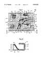
- FIG. 1is a fragmentary plan view of one embodiment of the improved screen assembly of the present invention with portions broken away to show various layers thereof;
- FIG. 2is a fragmentary enlarged cross sectional view taken substantially along line 2--2 of FIG. 1 and showing primarily the construction at the ends of the screen supporting plate for securing the vibratory screen in a vibratory screening machine;
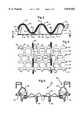
- FIG. 3is a fragmentary cross sectional view taken substantially along line 3--3 of FIG. 1;
- FIG. 4is a cross sectional view taken substantially along line 4--4 of FIG. 3;
- FIG. 5is a fragmentary end elevational view taken substantially in the direction of arrows 5--5 of FIG. 1 and showing, in addition to the screen, portions of a vibratory screen machine which may support the screen assembly;
- FIG. 6is an exploded perspective view showing the components of one embodiment of the screening portion of the screen assembly prior to being bonded together;
- FIG. 7is a fragmentary plan view of the preferred pattern of the perforated plastic grid which is used to bond the screens of the screen assembly together;
- FIG. 8is a schematic view showing the step of bonding the screens together by the use of the perforated plastic grid
- FIG. 8Ais a fragmentary end elevational view of the screen laminate after the individual screens have been bonded together;
- FIG. 9is a schematic view of the first step in the forming of the bonded screens into an undulating shape
- FIG. 9Ais a schematic view of the second step in forming the bonded screens into an undulating shape
- FIG. 9Bis a fragmentary diagrammatic view of the undulating screen immediately after it has been formed.
- FIG. 9Cis a fragmentary diagrammatic view of the undulating screen after its ends have been flattened
- FIG. 9Dis a fragmentary diagrammatic view of the undulating screen of FIG. 9C being aligned with the perforated plate to which it is to be bonded;
- FIG. 10is a reduced diagrammatic end elevational view showing the undulating screen being bonded to the perforated plate
- FIG. 11is a fragmentary perspective view showing the process of sealing the open ends of the ridges of the undulating screen
- FIG. 12is a fragmentary end elevational view showing the sealed ends of the ridges
- FIG. 13is a fragmentary cross sectional view taken substantially along line 13--13 of FIG. 12 showing the seals in the ends of the ridges;
- FIG. 14is a fragmentary plan view of an alternate pattern of a perforated plastic grid which can be used to bond the screens;
- FIG. 15is a fragmentary plan view of another pattern of a plastic grid which can be used for bonding the screens;
- FIG. 16is a fragmentary plan view of still another pattern of a plastic grid which can be used to bond the screens;
- FIG. 17is a fragmentary plan view of still another pattern of a plastic grid which can be used to bond the screens;
- FIG. 18is a fragmentary plan view of still another pattern of a plastic grid which can be used to bond the screens;
- FIG. 19is a fragmentary cross sectional view similar to FIG. 3 but showing another embodiment of the present invention.
- FIG. 20is a fragmentary plan view of a plurality of undulating screen assemblies aligned on the bed of a vibratory screening machine;
- FIG. 22is a fragmentary cross sectional view similar to FIG. 3 and showing still another embodiment of the present invention wherein coarse support screens are located on opposite sides of the two fine intermediate screens;
- FIG. 23is a fragmentary plan view of yet another embodiment of the present invention wherein the troughs are reinforced by fused plastic strip portions which extend length-wise of the troughs;
- FIG. 23Ais a fragmentary enlarged cross sectional view taken substantially along line 23A--23A of FIG. 23;
- FIG. 25is a fragmentary plan view of yet another embodiment of the present invention wherein the screens of the undulating screen subassembly are bonded to each other by strips of plastic which extend lengthwise of the troughs and ridges;
- FIG. 26is a fragmentary plan view of yet another embodiment of a plastic grid which can be used to bond the support and screening screens to each other into an undulating screen subassembly;
- FIG. 27is a fragmentary cross sectional view similar to FIG. 3 and showing yet another cross sectional configuration to which the screens can be formed;
- FIG. 28is a fragmentary plan view of another embodiment in which the screens of the undulating screen subassembly are bonded by plastic portions which are spots.
- FIGS. 1-5One embodiment of the improved screen assembly 10 is shown in FIGS. 1-5, and its method of fabrication is shown in FIGS. 6-13, and alternate configurations of a plastic grid which can be used in the process of fabricating the screen are shown in FIGS. 14-18, and alternate embodiments of the present invention are shown in FIG. 19, and in FIGS. 21-28.
- the improved screen assembly 10 of FIGS. 1-5includes a frame in the form of a perforated metal plate 11, such as steel or any other suitable metal, having a first pair of opposite edges 12 and 13 and a second pair of opposite edges 14 and 15 and an upper surface 16 and a lower surface 17.
- Plate 11includes apertures 19 which are bordered by elongated metal strip-like portions or members 20 which extend between edges 12 and 13 and by shorter strip-like portions 21 which extend lengthwise between elongated strip-like portions 20.
- the openings 19are formed by a punching operation and are quadrangles of approximately 1 inch square with rounded corners but they may be of any other desired shape or size.
- Strip-like portions 20 and 21are approximately 1/10 of an inch wide, but they may be of any desired width.
- the length of plate 11 between edges 12 and 13may be approximately 31/2 feet and its width between edges 14 and 15 may be approximately 21/2 feet, and it may have a thickness of about 1/16 of an inch. However, it will be appreciated that the size of plate 11 may vary as required to fit different machines.
- the width of each opening 19is a small fraction of the length of the plate between edges 12 and 13. The same is true of the relationship between the height of openings 19 and the width of the plate between edges 14 and 15.
- Channel-shaped members 22 and 23are mirror image counterparts and are constructed as shown in FIG. 2. More specifically, an extension 18 of plate 11 is folded into a channel-shaped configuration and a member 26 is bent to the shape shown in FIG. 2 from a single piece of metal and it brackets the edge 13 in the manner depicted in FIG.
- the screen subassembly 25includes a coarse screen 27 which serves a supporting function and may have a size of between 6 mesh and 20 mesh or any other suitable size.
- a fine screening screen 29is bonded to coarse supporting screen 27 and it may have a mesh size of between 30 mesh and 325 mesh, or any other suitable size.
- a finer screening screen 30is bonded to fine screening screen 29 and it may have a mesh size of between 40 mesh and 400 mesh, or any other suitable size.
- the intermediate fine screen 29should be two U.S.
- the three screens 27, 29 and 30are bonded to each other by a fused plastic grid 24 which permeates all three screens.
- the screen subassembly 25is formed in undulating curved shape, as depicted in FIG. 3, and it has ridges 31 and troughs 32.
- the undersides of troughs 32 at 33are bonded to plate 11 by a suitable adhesive such as epoxy. This bonding at 33 occurs at all areas where the undersides of the troughs 32 contact strips 20 and 21, as depicted in FIG. 4.
- the open ends of the ridges 31are sealed or blocked by polyurethane caps 34 which are molded into place in a manner which will be described hereafter relative to FIGS. 11-13.
- the screen assembly 10can be mounted in a vibrating screening machine 35 by means of elongated channel-shaped drawbars 37 and 39 which engage channels 22 and 23, respectively, and are drawn up by means of nut and bolt assemblies 40 and 41, respectively, as is well known in the art.
- Screen assembly 10rests on a well known type of frame (not fully shown) having a plurality of elongated members 42 and 43 extending parallel to channels 22 and 23. In its operative position, screen assembly 10 is bowed slightly so that its center along a line parallel to edges 12 and 13 is higher than the outer edges 12 and 13, as is well known.
- the screen assembly 10can be mounted in any other manner by any other type of mounting arrangement depending on the machine in which it is used.
- the channels 37, 39 and draw bolts 40, 41do not form any part of the present invention and are merely disclosed as being representative of one type of mounting, and it will be appreciated that other mounting structures known in the art may be utilized.
- the screen subassembly 25consisting of bonded screens 27, 29 and 30 is formed in the following manner, as schematically depicted in FIGS. 8, 8A, 9 and 9A-9D.
- the screens 27, 29 and 30 and the plastic grid 24are superimposed in contiguous abutting relationship in the order shown in FIG. 6, and suitable heat and pressure are applied to bond the foregoing parts into a unitary configuration wherein the plastic grid 24 fuses in a precisely controlled pattern and permeates the three screens 27, 29 and 30 and bonds them together, as can be seen from FIG. 1.
- the fact that the grid 24 fuses in a precisely controlled patternobviates the difficult requirement of precisely controlling the amount of adhesive which is applied.
- the screensare bonded with too much adhesive, such as epoxy, their open area is reduced, and if they are bonded with too little, they will not be attached to each other with sufficient strength. Furthermore, the use of a plastic grid enhances the ease of production.
- the plastic grid 24provides a gridwork within the screen assembly 25 wherein there are openings 44 (FIG. 1) between the plastic portions of the grid 24.
- a fragmentary plan view of the plastic gridis shown in FIG. 7 and it includes a border 45 and grid border portions 47 which outline openings 44.
- the plastic grid 24is preferably made of polyethylene, and in this instance it was approximately 0.062 inches thick in the form shown in FIG. 6, that is, before it was fused by heat and pressure into bonding relationship with screens 27, 29 and 30. The bonding was effected by pressing the superimposed abutting screens 27, 29 and 30 and plastic grid 24 with a heated platen. The temperature of the platen was approximately 450° F. and it was applied at a pressure of 12 psi for approximately two minutes.
- the polyethylene grid 24should be fused to a sufficient degree so that it will permeate the openings in screens 27, 29 and 30 and bond them together. It will be appreciated that any other suitable plastic, such as polypropylene, which is heat-fusible may be used. It will also be appreciated that the bonding temperatures, pressures, and times of pressing will vary with the plastic, its thickness, the types of screens being bonded, and other factors.
- the male diewill thus hold the previously formed undulation 53 against movement while the straight portion of laminate 25' which overlies cavity 52 is itself formed into an undulating shape 53a. It is to be noted that there is a clearance 55 at the entry portion between dies 50 and 51, and thus the straight portion of laminate 25' can move in the direction of arrow 57 as it is initially formed into configuration 53 and thereafter the straight portion can move in the direction of arrow 57 as the laminate is formed into undulation 53a. Thereafter, undulation 53 is placed into cavity 54', and undulation 53a is placed in cavity 54, and the next undulation is formed in cavity 52. The foregoing process is repeated until all of the undulations have been formed one at a time.
- the use of the polyethylene plastic for the bonding of the screensis beneficial because the polyethylene has a certain amount of yieldability, and thus when the undulations are formed as depicted in FIGS. 9 and 9A, the polyethylene bonding will yield slightly to permit relative movement between the separate screens 27, 29 and 30 as the laminate 25' is formed into an undulating shape.
- Thisis advantageous over the use of epoxy, such as used in the past, because the very fine mesh screens, such as those over 200 mesh, could tear when they are bent into a convex shape during the forming of the corrugations when the yielding was not experienced.
- the yieldability of the polyethylenepermits a certain amount of relative movement between the screens when they are subjected to high G forces in operation, thus lessening the tendency of the screen to tear and blind.
- plastic gridshave been used in the past to bond screening screens together which were utilized in vibratory screening machines in a flat condition rather than in an undulating shape.
- Flat plastic bonded screens of this prior typedid not function successfully in operation because the fused plastic grid permitted the screens to stretch when subjected to the high G forces encountered in operation. The reason that they stretched was that the entire width of the flat screens between their edges were unsupported.
- the unsupported spans in the corrugated screen of the present inventionis between troughs 32, and the stretching of the fused plastic is not a factor which adversely affects the operation. In fact, it is beneficial because it provides limited amounts of yieldability, as discussed above.
- the plastic gridpermits the screen subassembly to be formed into an undulating shape because the fused plastic will permit the fine wires of the screening screens to yield relative to the other wires to which they are bonded when they are formed into a convex shape at the crests of the undulations, thereby obviating the tearing which could otherwise occur when unyielding epoxy was used.
- the present undulating screenswill not yield excessively in operation because of the fact that the unsupported spans of screen are short, namely, from trough to trough, and the fused plastic is strong enough to maintain the required bond of the screens in such unsupported spans.
- the plastic gridgreatly simplifies fabrication of the undulating screen.
- the undulating screen subassembly 25After the undulating screen subassembly 25 has been completely formed in the manner described above relative to FIGS. 9 and 9A, it has the shape such as shown in FIG. 9B wherein the ends 25e are not flattened.
- the next step in fabricating the screen subassembly 25is to flatten the ends 25e as shown in FIG. 9C. Thereafter, the ends 25e are trimmed, if necessary, as depicted by dotted lines 25t so that a proper amount of flattened portion 25f remains for bonding to plate 11.
- the next step in the processis to locate the screen subassembly 25 on plate 11 in the following manner, as shown in FIG. 9D.
- the contacting portions of the screen subassembly 25 and plate 11are bonded to each other by epoxy, as mentioned above.
- This bondingis effected by dipping a heated perforated plate 11 into a fluidized powdered epoxy bed so that the powdered epoxy adheres to the plate.
- the plate with a layer of powdered epoxy thereonis then cooled. Thereafter, it is reheated to 350° F., and a suitable press (not shown) is used to hold the undersides of the troughs of the screen subassembly 25 in engagement with plate 11 for approximately three minutes and the epoxy will fuse into the undersides of the troughs of the screens. After the epoxy cools, the undulating screen will be bonded to the plate.
- the screen subassemblycan be adhesively secured to plate 11 by the use of liquid epoxy which is applied to the upper surface of the plate. It will be appreciated that any other suitable method of bonding the screen subassembly to the plate may be used.
- a chilled block 60is provided, and the edge of the screen assembly 10, such as 14, is placed in abutting relationship therewith.
- the blockis chilled to -50° F. by passing suitable refrigerant through a coil therein (not shown).
- a syringe, such as 61, containing liquid polyethyleneis inserted through various of the apertures 19 adjacent edge 14 to supply polyurethane of sufficient depth to form caps 34.
- the chilled plate 60hastens solidification of caps 34. The same procedure is applied at edge 15.
- caps 34permeate the screen subassembly 25 and also provide a seal with the edge portions 62 and 63 of edges 14 and 15, respectively.
- liquid epoxycan be used to produce caps 34.
- the ends of the ridgesmay be blocked by any other suitable method which may include but are not limited to those shown in copending patent application Ser. No. 08/062,464.
- FIGS. 14-18alternate configurations of plastic grids are disclosed.
- the grid 24a of FIG. 14is extremely similar to that of FIG. 7, the only difference being that the portions 47' are slightly thinner than portions 47 of FIG. 7 and also the crossover areas 67 are slightly smaller.
- the plastic grid 24bincludes a border portion 69 and the grid is in the form of square openings 70.
- the grid 24cincludes a border 71 and elongated rectangular openings 72.
- the grid 24dincludes a border portion 73 and rectangular openings, such as 74, which are staggered relative to each other.
- the grid 24e of FIG. 18includes a border portion 75 and square openings 77 which are staggered relative to each other as shown.
- FIG. 19another embodiment of the present invention is shown.
- Screen 10'differs from screen 10 in that the undulating screen subassembly 25' only has a support screen 27', which is analogous to screen 27, and a single screening screen 29', which is analogous to screen 29.
- the screens 27' and 29'are laminated to each other by the use of a plastic grid, such as 24, in the same manner as described above, and the laminate of screens 27' and 29', which are bonded by the fused plastic grid, is corrugated into an undulating shape in the manner described above, and thereafter bonded to an apertured plate 11 in the manner described above.
- the only difference between the structures of screen assemblies 10 and 10' and the methods of making thereofis that the former has a support screen and two screening screens, and the latter has a support screen and one screening screen.
- a screen which has proved satisfactory in testshad the following dimensions:
- the plate 11had the dimensions set forth above relative to FIGS. 1-5.
- the base screen 27was 20 mesh
- the intermediate screen 29was 180 mesh
- the uppermost screen 30was 210 mesh.
- the undulating screenhad a dimension of 1.6 inches between cycles, that is 1.6 inches between adjacent crests and 1.6 inches between the bottoms of adjacent troughs.
- the radius at the bottoms of the troughswas 1/4 inch and the radius at the crests was 1/2 inch.
- the height of the ridges from plate 11 to the tops of the ridgeswas one inch. It will be appreciated that the curvature may be of any desired dimension which will provide the proper results.
- FIG. 21another embodiment 80 of a screen assembly is disclosed.
- Screen assembly 80includes a perforated metal plate 11 which may be identical to plate 11 described above.
- Screen assembly 80includes a screen subassembly 81 consisting of a support screen 82, a finest screening screen 83, and a fine screening screen 84 which are bonded to each other by a fused plastic grid as described above relative to FIGS. 1-18.
- Screens 82, 83 and 84are analogous to screens 27, 30 and 29, respectively, of FIG. 3.
- the difference between the embodiment of FIG. 3 and the embodiment of FIG. 21is that the fine screening screen 83 is bonded to plate 11 and the finest screen 84 lies between it and coarse support screen 82, whereas in FIG.
- FIG. 21it is the support screen 27 which is bonded to the support plate, and the fine screen 29 lies between it and the finest screen 30.
- the advantage of the construction of FIG. 21is that the coarse support screen 82 protects the screening screens 83 and 84 from tearing and abrasion because it bears the brunt of the forces produced by the material which is being screened.
- all other parts of screen assembly 80may be identical to screen assembly 10 of FIGS. 1-5 and it may be fabricated in the same manner as described in the other portions of this specification.
- FIG. 22yet another embodiment of a screen assembly 85 is disclosed.
- the screen subassembly 87includes a coarse support screen 89, a fine screening screen 90, a finer screening screen 91 and a coarse support screen 92, all bonded together in the disclosed order in the manner described above relative to FIGS. 1-18.
- the coarse support screen 89is adjacent plate 1 and bonded thereto, and coarse support screen 92 overlies the finest screening screen 91, and support screen 92 serves the same purpose as coarse screen 81 of FIG. 21, namely, to protect screens 91 and 90 from abrasion and the forces to which they are subjected by the material which is being screened.
- the screen assembly 85is prepared in the same manner as described above relative to the preceding figures.
- the only difference between the embodiment of FIG. 22 and the embodiment of FIG. 3is that the embodiment of FIG. 22 has a coarse support screen 92 overlying the finest screening screen 91.
- the screen assembly 93includes a perforated plate 11, which is identical to plate 11 described above. Plate 11 has bonded thereto an undulating screen subassembly 94 which includes a coarse support screen 95, a fine screening screen 97, and an uppermost finest screening screen 99 which are bonded to each other by a plastic grid 100 of suitable plastic of the general type described above in the preceding figures, except that the grid 100 is of a different shape in that it has strips 101 which are crossed by strips 98.
- the screen assembly 93is fabricated in the same manner as described above relative to the preceding figures, except that the grid 100 is positioned so that strips 101 will be located at the bottoms of troughs 102. While a screen configuration such as shown in FIG. 3 is depicted in FIG. 23A, it will be understood that it can be of any other combination of screens such as shown in FIGS. 19, 21, 22 and 27, but not limited thereto.
- FIG. 24another embodiment of a screen assembly 103 is disclosed which includes a perforated plate 11 of the type described above and a bonded undulating screen subassembly 104 which may include any combination of screens, such as shown in FIGS. 3, 19, 21 and 22 or variations thereof except that they are bonded to each other by strips 105 of plastic rather than by a grid, such as shown in FIGS. 7, 14-18 and 23.
- the plastic strips 105extend perpendicularly to the ridges 107 and troughs 109.
- the plastic strips 105which fuse the screens to each other, may have the same physical parameters as described above relative to the grid of FIG. 7.
- FIG. 25yet another screen assembly 110 is disclosed wherein an undulating screen subassembly 111 is bonded to a perforated plate 11 of the type described above.
- Screen subassembly 111may be of the type shown in any of the FIGS. 3, 19, 21 and 22, or variations thereof.
- the individual screens of screen subassembly 111are bonded to each other by plastic strips 112 which extend longitudinally of the ridges 113 and grooves 114.
- the physical parameters of the plastic strips 112may be identical to those described above for the plastic grids which were used in the preceding figures. If desired, certain of the plastic strips may be oriented as shown in FIGS. 23 and 23A, namely, at the bottoms of the troughs.
- FIG. 26yet another embodiment of a plastic grid 115 is disclosed.
- Plastic grid 115differs from those shown in FIGS. 7 and 14-18 in that the cross strips 117 are much closer to each other and the cross strips 119 are much closer to each other so that the openings 120 between the strips are much smaller than the openings of the grids shown in FIGS. 7 and 14-18.
- the openings 120are 1.0 centimeters square and the border strips 117 and 119 are 0.1 centimeters wide, and the grid has a thickness of 0.0625 inches
- the openings 44are 2.54 centimeters square and the borders 47 are 0.125 inches wide. It will be appreciated that the borders widen as a result of fusing into the screens.
- FIG. 26The advantage of the construction of FIG. 26 is that the greater amount of plastic which is used to bond the screen subassemblies, such as shown in FIGS. 3, 19, 21 and 22, provides the screen subassembly in which it is used with greater resistance to abrasion and wear than those screen subassemblies which use grids which have larger openings between the plastic portions.
- the screen assembly 122includes a perforated plate 11 of the type described above and a screen subassembly 123 which is bonded thereto in the above-described manner.
- the screen subassembly 123which shown as being of the type of FIG. 3, can alternately be of the types shown in the other figures, such as 19, 21 and 22 or any of the other types. The only difference is in the manner in which the undulations are formed. In this respect, each ridge 124 has a very shallow curvature while each trough 125 has a sharper curvature.
- the advantage of the foregoing constructionis that the fine screening screens at the ridges 124 have less stress placed on them during the process of forming them from a planar screen subassembly, such as shown in FIG. 8A. More specifically, it can be seen that the finer screening screens at the crest of the ridges are stretched during the forming process and it will be appreciated that the less they are stretched, the less likely they are to tear. Conversely, the relatively sharp curvatures at the troughs 125 do not exert stretching on the uppermost fine screening screens while the lowermost coarse support screen which faces perforated plate 11 can bear the stress resulting from forming the sharp curvature without tearing.
- FIG. 28an embodiment is shown wherein the screens of the screen subassembly 130 are bonded by spaced circular spots 131 of the same type of plastic described above. Spots 131 may be of any desired size and preferably may be about one centimeter in diameter and be spaced any desired amount.
- the screen subassembly 130may be any of the combinations of screens described above relative to FIGS. 3, 19, 21 and 22, and the subassembly is bonded to plate 11 in the above-described manner.
- the screen subassemblies 80 and 85 of FIGS. 21 and 22are variant forms of the previously disclosed screen subassemblies of FIGS. 3 and 19 in that the screens are oriented differently.
- the screen subassemblies of FIGS. 21 and 22are fabricated in the same manner as described above relative to the screen subassembly 25 of FIG. 3.
- the screen subassemblies of FIGS. 23, 24, 25 and 28may comprise any of the screen orientations shown in FIGS. 3, 19, 21 and 22.
- the only difference between the embodiments of FIGS. 24 and 25 relative to the preceding embodiments of FIGS. 3, 19, 21 and 22is that the screen subassemblies 104 and 111 of FIGS. 24 and 25, respectively, are bonded to each other by strips of plastic rather than by grids.
- FIGS. 3, 19, 21 and 22different screen subassemblies of the types shown in FIGS. 3, 19, 21 and 22 can be interchangeably bonded to a plate 11 as desired for any particular vibratory screening function, depending on the characteristics which are desired.
- any of the individual screens of FIGS. 3, 19, 21 and 22may be bonded to each other by any of the preceding described grids, strips or spots, as desired.
- the plate 11 which has been shown in the various figuresis described in detail relative to FIGS. 1-5.
- the bonding process of fusing the plastic into the layered screensis the same regardless of whether the plastic is in the form of a grid, strips or spots.
- the original plasticis 0.0625 inches thick before it fuses into the screens and spreads out laterally, but it can be of any other suitable thickness.
- the primary criterionis that it should be sufficiently thick so as to penetrate all of the screens of the laminate.
- FIGS. 1-5While the preferred embodiment of the present invention for general purposes is shown in FIGS. 1-5, it will be appreciated that the other embodiments, such as shown in FIGS. 19 and 21-28 may be preferred for applications wherein their particular characteristics are desired or where the characteristics of the embodiment of FIGS. 1-5 are not needed.
- the screen assemblies described abovecan be utilized for dry screening, or can be utilized for wet screening of drilling mud which is a slurry of mud and water, and it can also be utilized for other liquid suspensions, such as kaolin and water.
- a machine of the type which performs a wet screening operationis disclosed in U.S. Pat. No. 4,882,054.
- the improved screen assembly 10 of the present inventionin addition to having all of the advantages enumerated above, also has all of the advantages of the screen assemblies disclosed in copending patent application Ser. No. 08/062,464, now U.S. Pat. No. 5,417,858 which is incorporated herein by reference, and it will be appreciated that various alternate constructions shown in said prior copending patent application can be used with the fused screen subassembly of the present invention provided they are not inconsistent therewith.
Landscapes
- Chemical & Material Sciences (AREA)
- Chemical Kinetics & Catalysis (AREA)
- Engineering & Computer Science (AREA)
- Manufacturing & Machinery (AREA)
- Combined Means For Separation Of Solids (AREA)
- Filtering Materials (AREA)
- Lining Or Joining Of Plastics Or The Like (AREA)
Abstract
Description
Claims (24)
Priority Applications (1)
| Application Number | Priority Date | Filing Date | Title |
|---|---|---|---|
| US08/955,340US5876552A (en) | 1993-01-13 | 1997-10-21 | Method of fabricating screen for vibratory screening machine |
Applications Claiming Priority (6)
| Application Number | Priority Date | Filing Date | Title |
|---|---|---|---|
| US412293A | 1993-01-13 | 1993-01-13 | |
| US08/062,464US5417858A (en) | 1993-01-13 | 1993-05-14 | Screen assembly for vibrating screening machine |
| US12780093A | 1993-09-28 | 1993-09-28 | |
| US08/273,217US5417859A (en) | 1993-01-13 | 1994-07-11 | Undulating screen for vibratory screening machine and method of fabrication thereof |
| US08/443,377US5783077A (en) | 1993-01-13 | 1995-05-17 | Undulating screen for vibratory screening machine |
| US08/955,340US5876552A (en) | 1993-01-13 | 1997-10-21 | Method of fabricating screen for vibratory screening machine |
Related Parent Applications (1)
| Application Number | Title | Priority Date | Filing Date |
|---|---|---|---|
| US08/443,377ContinuationUS5783077A (en) | 1993-01-13 | 1995-05-17 | Undulating screen for vibratory screening machine |
Publications (1)
| Publication Number | Publication Date |
|---|---|
| US5876552Atrue US5876552A (en) | 1999-03-02 |
Family
ID=27357567
Family Applications (4)
| Application Number | Title | Priority Date | Filing Date |
|---|---|---|---|
| US08/273,217Expired - LifetimeUS5417859A (en) | 1993-01-13 | 1994-07-11 | Undulating screen for vibratory screening machine and method of fabrication thereof |
| US08/289,500Expired - LifetimeUS5417793A (en) | 1993-01-13 | 1994-08-11 | Undulating screen for vibratory screening machine and method of fabrication thereof |
| US08/443,377Expired - LifetimeUS5783077A (en) | 1993-01-13 | 1995-05-17 | Undulating screen for vibratory screening machine |
| US08/955,340Expired - LifetimeUS5876552A (en) | 1993-01-13 | 1997-10-21 | Method of fabricating screen for vibratory screening machine |
Family Applications Before (3)
| Application Number | Title | Priority Date | Filing Date |
|---|---|---|---|
| US08/273,217Expired - LifetimeUS5417859A (en) | 1993-01-13 | 1994-07-11 | Undulating screen for vibratory screening machine and method of fabrication thereof |
| US08/289,500Expired - LifetimeUS5417793A (en) | 1993-01-13 | 1994-08-11 | Undulating screen for vibratory screening machine and method of fabrication thereof |
| US08/443,377Expired - LifetimeUS5783077A (en) | 1993-01-13 | 1995-05-17 | Undulating screen for vibratory screening machine |
Country Status (8)
| Country | Link |
|---|---|
| US (4) | US5417859A (en) |
| EP (1) | EP0680385B1 (en) |
| AU (1) | AU690096B2 (en) |
| CA (1) | CA2152602C (en) |
| DE (1) | DE69420701T2 (en) |
| DK (1) | DK0680385T3 (en) |
| ES (1) | ES2135563T3 (en) |
| WO (1) | WO1994015723A1 (en) |
Cited By (74)
| Publication number | Priority date | Publication date | Assignee | Title |
|---|---|---|---|---|
| US5971159A (en) | 1993-04-30 | 1999-10-26 | Tuboscope I/P, Inc. | Screen assembly for a vibratory separator |
| US6029824A (en)* | 1994-03-30 | 2000-02-29 | Tuboscope I/P, Inc. | Screen for vibrating separator |
| US6053332A (en)* | 1993-01-13 | 2000-04-25 | Derrick Manufacturing Corporation | Method of fabricating undulating screen for vibratory screening machine |
| USD425531S (en)* | 1999-03-29 | 2000-05-23 | Tuboscope I/P, Inc. | Screen |
| WO2000066281A1 (en)* | 1999-05-03 | 2000-11-09 | Usf Johnson Screens Pty Ltd | Screening equipment |
| US6152307A (en) | 1993-04-30 | 2000-11-28 | Tuboscope I/P, Inc. | Vibratory separator screens |
| US6186337B1 (en) | 1998-10-30 | 2001-02-13 | Tuboscope I/P, Inc. | Dual screen element having upper scalping screen adhered to crests of corrugated lower screen |
| US6202856B1 (en)* | 1999-09-22 | 2001-03-20 | Emerson Electric Co. | Vibratory screening system and screen therefor |
| US6209726B1 (en)* | 1999-06-28 | 2001-04-03 | Robert L. Gallia | Screen assembly for vibratory screening machine |
| US6220449B1 (en) | 1999-10-01 | 2001-04-24 | Tuboscope I/P, Inc. | Flat top cloth support screen |
| US6241098B1 (en) | 1999-06-24 | 2001-06-05 | Tubo Scope I/P, Inc. | Drilling fluid treatment operations and apparatuses |
| US6267247B1 (en) | 1993-04-30 | 2001-07-31 | Tuboscope I/P, Inc. | Vibratory separator screen |
| US6269953B1 (en) | 1993-04-30 | 2001-08-07 | Tuboscope I/P, Inc. | Vibratory separator screen assemblies |
| US6283302B1 (en) | 1993-08-12 | 2001-09-04 | Tuboscope I/P, Inc. | Unibody screen structure |
| US6290068B1 (en) | 1993-04-30 | 2001-09-18 | Tuboscope I/P, Inc. | Shaker screens and methods of use |
| US6325216B1 (en) | 1993-04-30 | 2001-12-04 | Tuboscope I/P, Inc. | Screen apparatus for vibratory separator |
| US6371306B2 (en)* | 1999-11-03 | 2002-04-16 | Tuboscope I/P, Inc. | Lost circulation fluid treatment |
| US6371302B1 (en) | 1993-04-30 | 2002-04-16 | Tuboscope I/P, Inc. | Vibratory separator screens |
| US6371301B1 (en) | 2000-11-17 | 2002-04-16 | Varco I/P, Inc. | Screen basket for shale shakers |
| US6401934B1 (en) | 1993-04-30 | 2002-06-11 | Tuboscope I/P, Inc. | Ramped screen & vibratory separator system |
| US6431368B1 (en)* | 2000-07-05 | 2002-08-13 | Emerson Electric Co. | Vibratory screen |
| US6443310B1 (en) | 1993-04-30 | 2002-09-03 | Varco I/P, Inc. | Seal screen structure |
| US6450345B1 (en) | 1993-04-30 | 2002-09-17 | Varco I/P, Inc. | Glue pattern screens and methods of production |
| US6454099B1 (en) | 1993-04-30 | 2002-09-24 | Varco I/P, Inc | Vibrator separator screens |
| US6458283B1 (en) | 1999-11-03 | 2002-10-01 | Varco I/P, Inc. | Lost circulation fluid treatment |
| US6457588B1 (en) | 1999-11-03 | 2002-10-01 | Varco I/P, Inc. | Treatment of fluid having lost circulation material |
| US6484885B1 (en)* | 1998-05-01 | 2002-11-26 | Cpi Sales & Mfg., Inc. | Solids raised screens |
| US6510947B1 (en) | 1999-11-03 | 2003-01-28 | Varco I/P, Inc. | Screens for vibratory separators |
| US20030042179A1 (en)* | 1998-10-30 | 2003-03-06 | Adams Thomas C. | Vibratory separator screens |
| US6565698B1 (en) | 1993-04-30 | 2003-05-20 | Varco I/P, Inc. | Method for making vibratory separator screens |
| US6581781B1 (en) | 1993-04-30 | 2003-06-24 | Tuboscope I/P, Inc. | Vibrator separator screens |
| US6607080B2 (en) | 1993-04-30 | 2003-08-19 | Varco I/P, Inc. | Screen assembly for vibratory separators |
| US6629610B1 (en) | 1993-04-30 | 2003-10-07 | Tuboscope I/P, Inc. | Screen with ramps for vibratory separator system |
| US20030222032A1 (en)* | 2002-05-29 | 2003-12-04 | Rudiger Tueshaus | Filtering screen construction and methods |
| US20040007508A1 (en)* | 1999-12-04 | 2004-01-15 | Schulte David L. | Screen assembly for vibratory separator |
| US20040065627A1 (en)* | 2002-07-08 | 2004-04-08 | Filtrox Ag | Precoat filter cartridge, precoat cartridge filter and use of a filter cartridge |
| US6722504B2 (en) | 1993-04-30 | 2004-04-20 | Varco I/P, Inc. | Vibratory separators and screens |
| US6726029B2 (en) | 2002-06-12 | 2004-04-27 | Varco I/P, Inc. | Separator screen with solids conveying end area |
| US6736270B2 (en) | 1998-10-30 | 2004-05-18 | Varco I/P, Inc. | Glued screens for shale shakers |
| US20040102117A1 (en)* | 2002-11-21 | 2004-05-27 | M-I L.L.C. | Vibratory screen |
| US20040251175A1 (en)* | 1998-10-30 | 2004-12-16 | Adams Thomas C. | Apparatuses and methods for making glued screen assemblies |
| US6932883B2 (en) | 1998-10-30 | 2005-08-23 | Varco I/P, Inc. | Screens for vibratory separators |
| US20050199532A1 (en)* | 2000-11-17 | 2005-09-15 | Schulte David L. | Screen basket and shale shakers |
| US20050274655A1 (en)* | 2004-06-15 | 2005-12-15 | Barrett Robert M | Screen assembly designed to conform to the radius of vibrating shakers with crowned decks |
| US20060011520A1 (en)* | 2000-11-17 | 2006-01-19 | Schulte David L | Dam basket for vibratory separators |
| US20060163122A1 (en)* | 2005-01-21 | 2006-07-27 | Bakula John J | Vibratory material screen with seal |
| US20070090045A1 (en)* | 2005-10-25 | 2007-04-26 | Bakula John J | Multidiameter wire cloth |
| US20070125687A1 (en)* | 2005-12-01 | 2007-06-07 | Kutryk Edward A | Screen assembly for a vibratory separator |
| US20070289273A1 (en)* | 2006-06-16 | 2007-12-20 | Boyd Kevin E | Air filter with pleat lock |
| US20080083660A1 (en)* | 2006-10-04 | 2008-04-10 | Gallia Robert L | Screen assembly for vibratory screening machine |
| US20090057205A1 (en)* | 2007-08-31 | 2009-03-05 | Schulte Jr David Lee | Vibratory separators and screens |
| US20090060955A1 (en)* | 2007-08-31 | 2009-03-05 | You Han Bae | Drug delivery vehicle that mimics viral properties |
| US20090308795A1 (en)* | 2008-06-16 | 2009-12-17 | M-I L.L.C. | Laminated screens |
| US7980392B2 (en) | 2007-08-31 | 2011-07-19 | Varco I/P | Shale shaker screens with aligned wires |
| US20110253602A1 (en)* | 2010-04-19 | 2011-10-20 | Derrick Corporation | Polyurethane vibratory screen |
| US8533974B2 (en) | 2006-10-04 | 2013-09-17 | Varco I/P, Inc. | Reclamation of components of wellbore cuttings material |
| US8561805B2 (en) | 2002-11-06 | 2013-10-22 | National Oilwell Varco, L.P. | Automatic vibratory separator |
| US20130277282A1 (en)* | 2010-04-19 | 2013-10-24 | Derrick Corporation | Polyurethane Vibratory Screen |
| US8695805B2 (en) | 2002-11-06 | 2014-04-15 | National Oilwell Varco, L.P. | Magnetic vibratory screen clamping |
| US20150190847A1 (en)* | 2010-04-19 | 2015-07-09 | Derrick Corporation | Polyurethane vibratory screen |
| US20150239014A1 (en)* | 2010-04-19 | 2015-08-27 | Derrick Corporation | Polyurethane screen |
| US20160059162A1 (en)* | 2013-04-30 | 2016-03-03 | M-I Drilling Fluids Uk Ltd. | Screen having frame members with angled surface(s) |
| US9643111B2 (en) | 2013-03-08 | 2017-05-09 | National Oilwell Varco, L.P. | Vector maximizing screen |
| US9677353B2 (en) | 2008-10-10 | 2017-06-13 | National Oilwell Varco, L.P. | Shale shakers with selective series/parallel flow path conversion |
| US10576502B2 (en) | 2012-05-25 | 2020-03-03 | Derrick Corporation | Injection molded screening apparatuses and methods |
| US10933444B2 (en) | 2012-05-25 | 2021-03-02 | Derrick Corporation | Injection molded screening apparatuses and methods |
| USD915484S1 (en) | 2017-06-06 | 2021-04-06 | Derrick Corporation | Interstage screen basket |
| US11161150B2 (en) | 2012-05-25 | 2021-11-02 | Derrick Corporation | Injection molded screening apparatuses and methods |
| US11198155B2 (en) | 2012-05-25 | 2021-12-14 | Derrick Corporation | Injection molded screening apparatuses and methods |
| US11203678B2 (en) | 2017-04-28 | 2021-12-21 | Derrick Corporation | Thermoplastic compositions, methods, apparatus, and uses |
| US11213857B2 (en) | 2017-06-06 | 2022-01-04 | Derrick Corporation | Method and apparatus for screening |
| US11458505B2 (en) | 2017-09-01 | 2022-10-04 | Derrick Corporation | Deblinding apparatuses and methods for screening |
| US11505638B2 (en) | 2017-04-28 | 2022-11-22 | Derrick Corporation | Thermoplastic compositions, methods, apparatus, and uses |
| US11772130B2 (en) | 2020-12-23 | 2023-10-03 | Continental Wire Cloth, LLC | Shaker screen assembly with undulation sealing tabs |
Families Citing this family (72)
| Publication number | Priority date | Publication date | Assignee | Title |
|---|---|---|---|---|
| ES2135563T3 (en)* | 1993-01-13 | 1999-11-01 | Derrick Mfg Corp | WAVY SCREEN FOR A VIBRATORY SCREENING MACHINE AND MANUFACTURING METHOD THEREOF. |
| US6000556A (en)* | 1993-01-13 | 1999-12-14 | Derrick Manufacturing Corporation | Screen assembly for vibratory screening machine |
| US5598930A (en)* | 1995-07-20 | 1997-02-04 | Advanced Wirecloth, Inc. | Shale shaker screen |
| DE4402547C1 (en)* | 1994-01-28 | 1995-03-23 | Stockhausen Chem Fab Gmbh | Apparatus and process for dissolving water-soluble, pulverulent polymers |
| US5551575A (en)* | 1994-07-29 | 1996-09-03 | Environmental Procedures, Inc. | Shale shaker screens |
| US5624560A (en)* | 1995-04-07 | 1997-04-29 | Baker Hughes Incorporated | Wire mesh filter including a protective jacket |
| US5642781A (en)* | 1994-10-07 | 1997-07-01 | Baker Hughes Incorporated | Multi-passage sand control screen |
| US5597479A (en)* | 1995-01-25 | 1997-01-28 | Aqua-Ion Systems, Inc. | Electro-coalescence/magnetic separation (ECMS) system and components for removal of contaminants from water streams, including desalinization |
| US5673797A (en)* | 1995-03-29 | 1997-10-07 | Derrick Manufacturing Corporation | Screen assembly for vibratory screening machine and method of fabrication thereof |
| US6220448B1 (en) | 1995-03-29 | 2001-04-24 | Derrick Manufacturing Corporation | Screen assembly for vibratory screening machine |
| US5636749A (en)* | 1995-05-18 | 1997-06-10 | Derrick Manufacturing Corporation | Undulating screen for vibratory screening machine |
| US5611399A (en)* | 1995-11-13 | 1997-03-18 | Baker Hughes Incorporated | Screen and method of manufacturing |
| US5851393A (en)* | 1995-11-14 | 1998-12-22 | Emerson Electric Co. | Screen assembly |
| US5814218A (en)* | 1996-01-16 | 1998-09-29 | Cagle; William S. | Distorted rectangular filter cloth screen for vibrating screening machine |
| US5690826A (en)* | 1996-05-10 | 1997-11-25 | Cravello; William Myron | Shaker screen assembly |
| US5921399A (en)* | 1996-06-07 | 1999-07-13 | Derrick Corporation | Gumbo separator |
| JP3686918B2 (en)* | 1996-10-16 | 2005-08-24 | 森村興産株式会社 | Filtration device for solid-liquid separation of sewage, wastewater, etc. |
| US5744036A (en)* | 1997-02-03 | 1998-04-28 | Aaf International | Pleated filter arrangement |
| US5944197A (en)* | 1997-04-24 | 1999-08-31 | Southwestern Wire Cloth, Inc. | Rectangular opening woven screen mesh for filtering solid particles |
| US6439392B1 (en) | 1997-09-02 | 2002-08-27 | Southwestern Wire Cloth, Inc. | Vibrating screen assembly with tubular frame |
| US5967336A (en) | 1997-09-02 | 1999-10-19 | Southwestern Wire Cloth, Inc. | Vibrating screen assembly with improved frame |
| US5927511A (en)* | 1998-06-29 | 1999-07-27 | Southwestern Wire Cloth, Inc. | Flat screen panel for crowned deck vibrating shaker |
| US6179128B1 (en) | 1998-10-02 | 2001-01-30 | Tuboscope I/P, Inc. | Tension clamp and screen system |
| US6769550B2 (en) | 2002-01-16 | 2004-08-03 | Varco I/P, Inc. | Screen assemblies for shale shakers |
| US6669985B2 (en) | 1998-10-30 | 2003-12-30 | Varco I/P, Inc. | Methods for making glued shale shaker screens |
| US20050000865A1 (en)* | 1998-10-30 | 2005-01-06 | Schulte David L. | Screen assemblies and vibratory separators |
| US20040112522A1 (en)* | 1998-10-30 | 2004-06-17 | Ward Kerry T. | Automated methods for making screen assemblies for vibratory separators |
| US6662952B2 (en) | 2002-01-16 | 2003-12-16 | Varco I/P, Inc. | Shale shakers and screens for them |
| US20020104611A1 (en)* | 1998-10-30 | 2002-08-08 | Adams Thomas C. | Self-flattening screens for vibratory separators |
| US6053331A (en)* | 1998-11-17 | 2000-04-25 | Cravello; William M. | Non-tensioned shaker filter |
| US6669027B1 (en) | 1999-03-19 | 2003-12-30 | Derrick Manufacturing Corporation | Vibratory screening machine and vibratory screen and screen tensioning structure |
| US20050035033A1 (en)* | 1999-03-25 | 2005-02-17 | Adams Thomas C. | Methods for sealing screen assemblies on vibratory separators |
| US6305549B1 (en) | 1999-07-06 | 2001-10-23 | Southwestern Wire Cloth, Inc. | Vibrating screen assembly of dissimilar materials |
| DE19937338A1 (en)* | 1999-08-11 | 2001-02-15 | Steinbeck Job Jorik | Sieving device, method for producing a sieve and sieve for a sieving device |
| US6601709B2 (en) | 1999-09-03 | 2003-08-05 | Tuboscope I/P, Inc. | Screen support and screens for shale shakers |
| AT408953B (en)* | 2000-07-21 | 2002-04-25 | Md Technology Production Gmbh | GAS AND / OR LIQUID TRANSFERABLE FILTER MATERIAL |
| US20050103689A1 (en)* | 2001-10-19 | 2005-05-19 | Schulte David L.Jr. | Sealing screen assemblies and vibratory separators |
| US6955262B2 (en)* | 2003-05-02 | 2005-10-18 | Varco, I/P Inc. | Removable seal apparatus for vibratory separator |
| US20050224398A1 (en)* | 2001-10-19 | 2005-10-13 | Largent David W | Vibratory separators and sealing screens |
| GB0127085D0 (en)* | 2001-11-10 | 2002-01-02 | United Wire Ltd | Improved screen for separating solids from liquids |
| US20050067327A1 (en)* | 2002-01-16 | 2005-03-31 | Adams Thomas C. | Screen assemblies for shale shakers |
| US20050082236A1 (en)* | 2002-06-12 | 2005-04-21 | Derrick Corporation | Vibratory screening machine with suction and method for screening a slurry |
| US20050133465A1 (en)* | 2002-06-12 | 2005-06-23 | Derrick Corporation | Vibratory screen assembly and method of manufacture |
| US20030230541A1 (en)* | 2002-06-12 | 2003-12-18 | Derrick Mitchell J. | Vibratory screening machine with suction and pressure and method for screening a slurry |
| GB2394196A (en)* | 2002-10-17 | 2004-04-21 | Varco Int | Screen assembly for a shale shaker |
| US7264125B2 (en)* | 2003-04-23 | 2007-09-04 | Derrick Corporation | Undulating molded plastic vibratory screen |
| US7094297B2 (en)* | 2003-07-25 | 2006-08-22 | Yanco I/P, Inc. | Methods for making screen assemblies |
| US7011218B2 (en)* | 2003-08-29 | 2006-03-14 | Derrick Corporation | Vibratory screen assemblies |
| US8067464B2 (en) | 2004-10-04 | 2011-11-29 | Nitromed, Inc. | Compositions and methods using apocynin compounds and nitric oxide donors |
| US7648028B2 (en)* | 2005-04-22 | 2010-01-19 | Becton, Dickinson And Company | Adapter for multiple capacity needle immobilizing device |
| JP2006326515A (en)* | 2005-05-27 | 2006-12-07 | Aisan Ind Co Ltd | Filter |
| AU2005202795B2 (en)* | 2005-06-27 | 2007-05-17 | Symphony Wire Pty Ltd | Retention device for filter screen |
| WO2007016677A2 (en) | 2005-08-02 | 2007-02-08 | Nitromed, Inc. | Nitric oxide enhancing antimicrobial compounds, compositions and methods of use |
| US7838023B2 (en) | 2005-11-16 | 2010-11-23 | Nitromed, Inc. | Furoxan compounds, compositions and methods of use |
| US20110036759A1 (en)* | 2005-12-06 | 2011-02-17 | Rotex, Inc. | Screening machine and associated screen panel |
| US20070125688A1 (en)* | 2005-12-06 | 2007-06-07 | Rotex, Inc. | Screening machine, associated screen panel and seal |
| US8261915B2 (en) | 2005-12-06 | 2012-09-11 | Rotex Global, Llc | Screening machine and associated screen panel |
| AU2007243765A1 (en) | 2006-03-29 | 2007-11-08 | Nicox S.A. | Nitric oxide enhancing prostaglandin compounds, compositions and methods of use |
| US8142537B2 (en)* | 2009-03-17 | 2012-03-27 | Mann + Hummel Gmbh | Support grid and alignment appartus for a filter element and housing |
| US20100258481A1 (en)* | 2009-04-13 | 2010-10-14 | Helmy Nashat N | Sifting screen |
| US8353407B2 (en)* | 2009-07-22 | 2013-01-15 | Buffalo Wire Works Company | Apparatus and method for making wire screen |
| US8196753B2 (en)* | 2010-11-12 | 2012-06-12 | Polydeck Screen Corporation | Screening panel |
| GB201106298D0 (en)* | 2011-04-13 | 2011-05-25 | Bailey Marshall G | Screen assembly |
| US8893894B2 (en) | 2012-10-13 | 2014-11-25 | Buffalo Wire Works | Wire screen with flattened wire |
| WO2014109673A1 (en)* | 2013-01-09 | 2014-07-17 | Kostyuk Anatoliy Ivanovich | Panel with wave-shaped mesh cloth on a rigid frame for vibrating screening machines |
| DE102013000939A1 (en)* | 2013-01-19 | 2014-07-24 | Hydac Filtertechnik Gmbh | filter media |
| WO2017019580A1 (en)* | 2015-07-24 | 2017-02-02 | Schlumberger Technology Corporation | Perforated foil screen assembly |
| CN105817415A (en)* | 2016-04-29 | 2016-08-03 | 长兴谐达能源科技有限公司 | Drying and screening device for biomass particles |
| USD890236S1 (en) | 2019-02-07 | 2020-07-14 | Derrick Corporation | Vibratory screening machine |
| US11185801B2 (en) | 2016-10-14 | 2021-11-30 | Derrick Corporation | Apparatuses, methods, and systems for vibratory screening |
| JOP20190082A1 (en) | 2016-10-14 | 2019-04-14 | Dirrick Corp | Equipment, methods and systems for vibratory sorting |
| US11052427B2 (en) | 2016-10-14 | 2021-07-06 | Derrick Corporation | Apparatuses, methods, and systems for vibratory screening |
Citations (88)
| Publication number | Priority date | Publication date | Assignee | Title |
|---|---|---|---|---|
| BE505776A (en)* | ||||
| US40242A (en)* | 1863-10-13 | Improvement in grain-sieves | ||
| US246144A (en)* | 1881-08-23 | Fanning-mill | ||
| US275340A (en)* | 1883-04-03 | kimball | ||
| US500302A (en)* | 1893-06-27 | Slate-picker | ||
| US526562A (en)* | 1894-09-25 | Coal-screen | ||
| US560858A (en)* | 1896-05-26 | missroon | ||
| US607598A (en)* | 1898-07-19 | Grain-separating screen for th resh ing-ivlach in es | ||
| US691045A (en)* | 1900-11-09 | 1902-01-14 | William W Climenson | Machine for separating cockle from wheat. |
| US800693A (en)* | 1904-12-28 | 1905-10-03 | John A Traylor | Shaking-screen. |
| US964144A (en)* | 1907-08-16 | 1910-07-12 | Irenee Alexis Chavanne | Centrifugal bolting-machine. |
| US964897A (en)* | 1908-04-04 | 1910-07-19 | Noah Bryant | Save-all for paper-making machines. |
| US966578A (en)* | 1908-04-20 | 1910-08-09 | Sherman P Murphy | Screen for threshing-machines. |
| US984866A (en)* | 1909-05-06 | 1911-02-21 | Earl H Tate | Aero ore-concentrator and placer-machine. |
| US1009069A (en)* | 1911-04-26 | 1911-11-21 | Charles Hunnicutt | Seed-corn grader. |
| US1098979A (en)* | 1912-01-22 | 1914-06-02 | Karl Schuchard | Jigging-machine. |
| US1132667A (en)* | 1910-06-16 | 1915-03-23 | Louis Milliot | Florist's dirt-sieve. |
| US1269085A (en)* | 1917-02-26 | 1918-06-11 | Samuel A Jeske | Grain-separator. |
| US1423021A (en)* | 1919-09-22 | 1922-07-18 | Tyler Co W S | Screening apparatus |
| US1462804A (en)* | 1922-04-18 | 1923-07-24 | Evans Edward James | Sieve |
| US1561632A (en)* | 1924-02-27 | 1925-11-17 | Herbert S Woodward | Perforated indented screen |
| US1947307A (en)* | 1931-01-21 | 1934-02-13 | Rafton Engineering Corp | Means for supporting wire cloth |
| US1997713A (en)* | 1932-08-08 | 1935-04-16 | Tyler Co W S | Screen and method of making same |
| US1997740A (en)* | 1931-12-24 | 1935-04-16 | Tyler Co W S | Plural cloth screening apparatus |
| GB457924A (en)* | 1935-03-09 | 1936-12-09 | Tyler Co W S | Improvements in screening or sifting apparatus |
| US2082513A (en)* | 1934-07-26 | 1937-06-01 | Western States Machine Co | Filter sieve and art of making the same |
| US2089548A (en)* | 1935-03-12 | 1937-08-10 | Colorado Fuel & Iron Corp | Means of filtration |
| GB519680A (en)* | 1938-09-22 | 1940-04-03 | James Walker | Improvements in or relating to strainer plates and drums |
| US2274700A (en)* | 1939-02-14 | 1942-03-03 | Tyler Co W S | Screening apparatus |
| US2315055A (en)* | 1940-07-19 | 1943-03-30 | Richard D Heller | Screen cloth |
| US2406051A (en)* | 1943-06-26 | 1946-08-20 | Paul Porzelt | Apparatus for producing corrugated structures |
| US2462878A (en)* | 1942-11-23 | 1949-03-01 | Mining Process & Patent Co | Vibrating screen with vacuum control therefor |
| US2648441A (en)* | 1948-01-17 | 1953-08-11 | Productive Equipment Corp | Vibrating equipment |
| US2723032A (en)* | 1950-12-18 | 1955-11-08 | Mining Process & Patent Co | Vibrating screens |
| US2726184A (en)* | 1952-11-01 | 1955-12-06 | Purolator Products Inc | Method of providing seals for filters |
| GB743902A (en)* | 1951-04-12 | 1956-01-25 | Siteg Siebtech Gmbh | Vibrating screens |
| GB823648A (en)* | 1956-09-27 | 1959-11-18 | Air Maze Corp | Filters for fluids |
| US2929464A (en)* | 1959-05-18 | 1960-03-22 | Vernco Corp | Flat knit filter media |
| CA599661A (en)* | 1960-06-14 | H. Eaton-Williams Raymond | Fluid filters formed of fabrics containing thermoplastic yarns | |
| US2957235A (en)* | 1957-03-12 | 1960-10-25 | Purolator Products Inc | Method of joining powder metal parts |
| US2980208A (en)* | 1957-05-21 | 1961-04-18 | Delbag Luftfilter Gmbh | Filter element for extremely fine dust |
| US3057481A (en)* | 1958-06-12 | 1962-10-09 | Pall Corp | Corrugated filter and method of forming the same |
| US3165473A (en)* | 1960-10-24 | 1965-01-12 | Pall Corp | Corrugated filter unit |
| US3255885A (en)* | 1963-02-27 | 1966-06-14 | Nordberg Manufacturing Co | Vibrating screen |
| US3306794A (en)* | 1963-02-12 | 1967-02-28 | Wix Corp | Method of making a filter element |
| GB1106513A (en)* | 1964-09-26 | 1968-03-20 | Wehner Albert | Sieve machines |
| US3374886A (en)* | 1966-05-02 | 1968-03-26 | Arthur S. Lightsey | Grain separator chaffer assembly |
| US3465413A (en)* | 1966-10-25 | 1969-09-09 | Universal Filters Inc | Method of manufacturing pleated filters |
| GB1225849A (en)* | 1967-12-20 | 1971-03-24 | ||
| US3664503A (en)* | 1968-08-22 | 1972-05-23 | Stahlgruber Gruber & Co Otto | Elastic sieve bottom |
| US3747772A (en)* | 1971-05-21 | 1973-07-24 | Parker Hannifin Corp | Filter |
| US3853529A (en)* | 1971-06-09 | 1974-12-10 | Farr Co | Pleated air filter cartridge |
| US4019987A (en)* | 1976-01-14 | 1977-04-26 | Leonard L | Extended area filters |
| US4022596A (en)* | 1975-08-27 | 1977-05-10 | Pedersen George C | Porous packing and separator medium |
| US4033865A (en)* | 1974-12-09 | 1977-07-05 | Derrick Manufacturing Corporation | Non-clogging screen apparatus |
| US4064051A (en)* | 1972-06-02 | 1977-12-20 | Hein, Lehmann Akt. | Elastic transporting, sieving or filtering base with swinging drive |
| US4075106A (en)* | 1976-05-07 | 1978-02-21 | Masahiko Yamazaki | Filtering device |
| GB1512958A (en)* | 1975-10-06 | 1978-06-01 | Crosland Filters Ltd | Filter |
| JPS5532404A (en)* | 1978-08-24 | 1980-03-07 | Toshiba Corp | Controlling of induction motor |
| US4380494A (en)* | 1980-04-14 | 1983-04-19 | Litton Systems, Inc. | Vibrating screen with self-supporting screen cloth |
| GB2124099A (en)* | 1982-07-24 | 1984-02-15 | Parnaby Cyclones International | Dewatering and compacting screen |
| JPS59142818A (en)* | 1983-02-01 | 1984-08-16 | Seibu Giken:Kk | Manufacture of filter element |
| US4512892A (en)* | 1980-02-14 | 1985-04-23 | Millipore Corporation | Method and structure for sealing tubular filter elments |
| US4517090A (en)* | 1982-03-30 | 1985-05-14 | Baxter Travenol Laboratories, Inc. | Low volume, large area filters for IV or blood filtration |
| US4575421A (en)* | 1984-03-08 | 1986-03-11 | Derrick Manufacturing Corporation | Non-clogging wear-reducing screen assembly for vibrating screening machine |
| US4594162A (en)* | 1984-02-13 | 1986-06-10 | American Filtrona Corporation | Pleated filter and method and apparatus for fabricating same |
| US4617122A (en)* | 1984-08-01 | 1986-10-14 | Donaldson Company, Inc. | Crimp seal pleated filter assembly |
| US4647373A (en)* | 1984-08-30 | 1987-03-03 | Donaldson Company, Inc. | Multi-layered filter apparatus |
| US4696751A (en)* | 1986-08-04 | 1987-09-29 | Dresser Industries, Inc. | Vibratory screening apparatus and method for removing suspended solids from liquid |
| US4701197A (en)* | 1986-10-07 | 1987-10-20 | Allied Corp. | Molded panel filter |
| US4746339A (en)* | 1984-08-06 | 1988-05-24 | Tilghman Wheelabrator Limited | Filtering apparatus |
| US4758333A (en)* | 1987-03-23 | 1988-07-19 | General Electric Company | Sieve |
| US4820407A (en)* | 1987-04-24 | 1989-04-11 | Cpi Sales, Inc. | Solids screens |
| US4832834A (en)* | 1988-07-11 | 1989-05-23 | Baird Jr Howard R | Elastomer sieve screen |
| JPH01203010A (en)* | 1988-02-08 | 1989-08-15 | Goyo Kogyo Kk | Molding method for filter unit |
| WO1989010781A1 (en)* | 1988-05-04 | 1989-11-16 | Knecht Filterwerke Gmbh | Strips of filter material with moulded corrugations and filter bodies made of this material |
| US4882054A (en)* | 1988-08-22 | 1989-11-21 | Derrick Manufacturing Corporation | Vibratory screening machine with tiltable screen frame and adjustable discharge weir |
| DE3818972A1 (en)* | 1988-06-03 | 1990-02-08 | Hartwig Straub | Filter insert for a solids filter |
| US4940500A (en)* | 1987-08-31 | 1990-07-10 | Tsuchiya Mfg. Co., Ltd. | Filter medium forming system and process |
| US4954249A (en)* | 1988-06-10 | 1990-09-04 | Beloit Corporation | Wave screen plate |
| EP0453348A1 (en)* | 1990-04-18 | 1991-10-23 | E & M LAMORT | Screen for straining a classification of paper pulp |
| US5084178A (en)* | 1988-06-15 | 1992-01-28 | Pall Corporation | Corrugated filter arrangement with support layer and flow channels |
| US5139154A (en)* | 1989-12-27 | 1992-08-18 | Beloit Corporation | Wear screen plate and method of manufacture thereof |
| US5167740A (en)* | 1990-01-25 | 1992-12-01 | Carl Freudenberg | Method of making a filter insert of nonwoven material in the form of a pleated pack |
| US5221008A (en)* | 1990-05-11 | 1993-06-22 | Derrick Manufacturing Corporation | Vibratory screening machine and non-clogging wear-reducing screen assembly therefor |
| US5230455A (en)* | 1991-11-11 | 1993-07-27 | British United Shoe Machinery Limited | Self-supporting filter units |
| US5312508A (en)* | 1992-10-16 | 1994-05-17 | John Chisholm | Attaching crimped wire mesh to an object requiring heat transfer |
| US5417859A (en)* | 1993-01-13 | 1995-05-23 | Derrick Manufacturing Corporation | Undulating screen for vibratory screening machine and method of fabrication thereof |
Family Cites Families (2)
| Publication number | Priority date | Publication date | Assignee | Title |
|---|---|---|---|---|
| FR2559679B1 (en)* | 1984-02-17 | 1991-06-14 | Transfer Technology Internatio | CANVAS FOR A VIBRATING OR SHAKER SCREEN |
| EP0479385B1 (en)* | 1990-10-03 | 1995-12-27 | Industria Grafica Meschi S.r.l. | Apparatus for the high speed piling up of paper sheets or continuous band with, tearing separation along preperforation lines |
- 1994
- 1994-01-07ESES94907163Tpatent/ES2135563T3/ennot_activeExpired - Lifetime
- 1994-01-07WOPCT/US1994/000242patent/WO1994015723A1/enactiveIP Right Grant
- 1994-01-07CACA002152602Apatent/CA2152602C/ennot_activeExpired - Lifetime
- 1994-01-07AUAU60844/94Apatent/AU690096B2/ennot_activeExpired
- 1994-01-07EPEP94907163Apatent/EP0680385B1/ennot_activeExpired - Lifetime
- 1994-01-07DEDE69420701Tpatent/DE69420701T2/ennot_activeExpired - Lifetime
- 1994-01-07DKDK94907163Tpatent/DK0680385T3/enactive
- 1994-07-11USUS08/273,217patent/US5417859A/ennot_activeExpired - Lifetime
- 1994-08-11USUS08/289,500patent/US5417793A/ennot_activeExpired - Lifetime
- 1995
- 1995-05-17USUS08/443,377patent/US5783077A/ennot_activeExpired - Lifetime
- 1997
- 1997-10-21USUS08/955,340patent/US5876552A/ennot_activeExpired - Lifetime
Patent Citations (89)
| Publication number | Priority date | Publication date | Assignee | Title |
|---|---|---|---|---|
| US560858A (en)* | 1896-05-26 | missroon | ||
| US40242A (en)* | 1863-10-13 | Improvement in grain-sieves | ||
| US246144A (en)* | 1881-08-23 | Fanning-mill | ||
| US275340A (en)* | 1883-04-03 | kimball | ||
| US500302A (en)* | 1893-06-27 | Slate-picker | ||
| US526562A (en)* | 1894-09-25 | Coal-screen | ||
| BE505776A (en)* | ||||
| US607598A (en)* | 1898-07-19 | Grain-separating screen for th resh ing-ivlach in es | ||
| CA599661A (en)* | 1960-06-14 | H. Eaton-Williams Raymond | Fluid filters formed of fabrics containing thermoplastic yarns | |
| US691045A (en)* | 1900-11-09 | 1902-01-14 | William W Climenson | Machine for separating cockle from wheat. |
| US800693A (en)* | 1904-12-28 | 1905-10-03 | John A Traylor | Shaking-screen. |
| US964144A (en)* | 1907-08-16 | 1910-07-12 | Irenee Alexis Chavanne | Centrifugal bolting-machine. |
| US964897A (en)* | 1908-04-04 | 1910-07-19 | Noah Bryant | Save-all for paper-making machines. |
| US966578A (en)* | 1908-04-20 | 1910-08-09 | Sherman P Murphy | Screen for threshing-machines. |
| US984866A (en)* | 1909-05-06 | 1911-02-21 | Earl H Tate | Aero ore-concentrator and placer-machine. |
| US1132667A (en)* | 1910-06-16 | 1915-03-23 | Louis Milliot | Florist's dirt-sieve. |
| US1009069A (en)* | 1911-04-26 | 1911-11-21 | Charles Hunnicutt | Seed-corn grader. |
| US1098979A (en)* | 1912-01-22 | 1914-06-02 | Karl Schuchard | Jigging-machine. |
| US1269085A (en)* | 1917-02-26 | 1918-06-11 | Samuel A Jeske | Grain-separator. |
| US1423021A (en)* | 1919-09-22 | 1922-07-18 | Tyler Co W S | Screening apparatus |
| US1462804A (en)* | 1922-04-18 | 1923-07-24 | Evans Edward James | Sieve |
| US1561632A (en)* | 1924-02-27 | 1925-11-17 | Herbert S Woodward | Perforated indented screen |
| US1947307A (en)* | 1931-01-21 | 1934-02-13 | Rafton Engineering Corp | Means for supporting wire cloth |
| US1997740A (en)* | 1931-12-24 | 1935-04-16 | Tyler Co W S | Plural cloth screening apparatus |
| US1997713A (en)* | 1932-08-08 | 1935-04-16 | Tyler Co W S | Screen and method of making same |
| US2082513A (en)* | 1934-07-26 | 1937-06-01 | Western States Machine Co | Filter sieve and art of making the same |
| GB457924A (en)* | 1935-03-09 | 1936-12-09 | Tyler Co W S | Improvements in screening or sifting apparatus |
| US2089548A (en)* | 1935-03-12 | 1937-08-10 | Colorado Fuel & Iron Corp | Means of filtration |
| GB519680A (en)* | 1938-09-22 | 1940-04-03 | James Walker | Improvements in or relating to strainer plates and drums |
| US2274700A (en)* | 1939-02-14 | 1942-03-03 | Tyler Co W S | Screening apparatus |
| US2315055A (en)* | 1940-07-19 | 1943-03-30 | Richard D Heller | Screen cloth |
| US2462878A (en)* | 1942-11-23 | 1949-03-01 | Mining Process & Patent Co | Vibrating screen with vacuum control therefor |
| US2406051A (en)* | 1943-06-26 | 1946-08-20 | Paul Porzelt | Apparatus for producing corrugated structures |
| US2648441A (en)* | 1948-01-17 | 1953-08-11 | Productive Equipment Corp | Vibrating equipment |
| US2723032A (en)* | 1950-12-18 | 1955-11-08 | Mining Process & Patent Co | Vibrating screens |
| GB743902A (en)* | 1951-04-12 | 1956-01-25 | Siteg Siebtech Gmbh | Vibrating screens |
| US2726184A (en)* | 1952-11-01 | 1955-12-06 | Purolator Products Inc | Method of providing seals for filters |
| GB823648A (en)* | 1956-09-27 | 1959-11-18 | Air Maze Corp | Filters for fluids |
| US2957235A (en)* | 1957-03-12 | 1960-10-25 | Purolator Products Inc | Method of joining powder metal parts |
| US2980208A (en)* | 1957-05-21 | 1961-04-18 | Delbag Luftfilter Gmbh | Filter element for extremely fine dust |
| US3057481A (en)* | 1958-06-12 | 1962-10-09 | Pall Corp | Corrugated filter and method of forming the same |
| US2929464A (en)* | 1959-05-18 | 1960-03-22 | Vernco Corp | Flat knit filter media |
| US3165473A (en)* | 1960-10-24 | 1965-01-12 | Pall Corp | Corrugated filter unit |
| US3306794A (en)* | 1963-02-12 | 1967-02-28 | Wix Corp | Method of making a filter element |
| US3255885A (en)* | 1963-02-27 | 1966-06-14 | Nordberg Manufacturing Co | Vibrating screen |
| GB1106513A (en)* | 1964-09-26 | 1968-03-20 | Wehner Albert | Sieve machines |
| US3374886A (en)* | 1966-05-02 | 1968-03-26 | Arthur S. Lightsey | Grain separator chaffer assembly |
| US3465413A (en)* | 1966-10-25 | 1969-09-09 | Universal Filters Inc | Method of manufacturing pleated filters |
| GB1225849A (en)* | 1967-12-20 | 1971-03-24 | ||
| US3664503A (en)* | 1968-08-22 | 1972-05-23 | Stahlgruber Gruber & Co Otto | Elastic sieve bottom |
| US3747772A (en)* | 1971-05-21 | 1973-07-24 | Parker Hannifin Corp | Filter |
| US3853529A (en)* | 1971-06-09 | 1974-12-10 | Farr Co | Pleated air filter cartridge |
| US4064051A (en)* | 1972-06-02 | 1977-12-20 | Hein, Lehmann Akt. | Elastic transporting, sieving or filtering base with swinging drive |
| US4033865A (en)* | 1974-12-09 | 1977-07-05 | Derrick Manufacturing Corporation | Non-clogging screen apparatus |
| US4022596A (en)* | 1975-08-27 | 1977-05-10 | Pedersen George C | Porous packing and separator medium |
| GB1512958A (en)* | 1975-10-06 | 1978-06-01 | Crosland Filters Ltd | Filter |
| US4019987A (en)* | 1976-01-14 | 1977-04-26 | Leonard L | Extended area filters |
| US4075106A (en)* | 1976-05-07 | 1978-02-21 | Masahiko Yamazaki | Filtering device |
| JPS5532404A (en)* | 1978-08-24 | 1980-03-07 | Toshiba Corp | Controlling of induction motor |
| US4512892A (en)* | 1980-02-14 | 1985-04-23 | Millipore Corporation | Method and structure for sealing tubular filter elments |
| US4380494A (en)* | 1980-04-14 | 1983-04-19 | Litton Systems, Inc. | Vibrating screen with self-supporting screen cloth |
| US4517090A (en)* | 1982-03-30 | 1985-05-14 | Baxter Travenol Laboratories, Inc. | Low volume, large area filters for IV or blood filtration |
| GB2124099A (en)* | 1982-07-24 | 1984-02-15 | Parnaby Cyclones International | Dewatering and compacting screen |
| JPS59142818A (en)* | 1983-02-01 | 1984-08-16 | Seibu Giken:Kk | Manufacture of filter element |
| US4594162A (en)* | 1984-02-13 | 1986-06-10 | American Filtrona Corporation | Pleated filter and method and apparatus for fabricating same |
| US4575421A (en)* | 1984-03-08 | 1986-03-11 | Derrick Manufacturing Corporation | Non-clogging wear-reducing screen assembly for vibrating screening machine |
| US4617122A (en)* | 1984-08-01 | 1986-10-14 | Donaldson Company, Inc. | Crimp seal pleated filter assembly |
| US4746339A (en)* | 1984-08-06 | 1988-05-24 | Tilghman Wheelabrator Limited | Filtering apparatus |
| US4647373A (en)* | 1984-08-30 | 1987-03-03 | Donaldson Company, Inc. | Multi-layered filter apparatus |
| US4696751A (en)* | 1986-08-04 | 1987-09-29 | Dresser Industries, Inc. | Vibratory screening apparatus and method for removing suspended solids from liquid |
| US4701197A (en)* | 1986-10-07 | 1987-10-20 | Allied Corp. | Molded panel filter |
| US4758333A (en)* | 1987-03-23 | 1988-07-19 | General Electric Company | Sieve |
| US4820407A (en)* | 1987-04-24 | 1989-04-11 | Cpi Sales, Inc. | Solids screens |
| US4940500A (en)* | 1987-08-31 | 1990-07-10 | Tsuchiya Mfg. Co., Ltd. | Filter medium forming system and process |
| JPH01203010A (en)* | 1988-02-08 | 1989-08-15 | Goyo Kogyo Kk | Molding method for filter unit |
| WO1989010781A1 (en)* | 1988-05-04 | 1989-11-16 | Knecht Filterwerke Gmbh | Strips of filter material with moulded corrugations and filter bodies made of this material |
| DE3818972A1 (en)* | 1988-06-03 | 1990-02-08 | Hartwig Straub | Filter insert for a solids filter |
| US4954249A (en)* | 1988-06-10 | 1990-09-04 | Beloit Corporation | Wave screen plate |
| US5084178A (en)* | 1988-06-15 | 1992-01-28 | Pall Corporation | Corrugated filter arrangement with support layer and flow channels |
| US4832834A (en)* | 1988-07-11 | 1989-05-23 | Baird Jr Howard R | Elastomer sieve screen |
| US4882054A (en)* | 1988-08-22 | 1989-11-21 | Derrick Manufacturing Corporation | Vibratory screening machine with tiltable screen frame and adjustable discharge weir |
| US5139154A (en)* | 1989-12-27 | 1992-08-18 | Beloit Corporation | Wear screen plate and method of manufacture thereof |
| US5167740A (en)* | 1990-01-25 | 1992-12-01 | Carl Freudenberg | Method of making a filter insert of nonwoven material in the form of a pleated pack |
| EP0453348A1 (en)* | 1990-04-18 | 1991-10-23 | E & M LAMORT | Screen for straining a classification of paper pulp |
| US5221008A (en)* | 1990-05-11 | 1993-06-22 | Derrick Manufacturing Corporation | Vibratory screening machine and non-clogging wear-reducing screen assembly therefor |
| US5230455A (en)* | 1991-11-11 | 1993-07-27 | British United Shoe Machinery Limited | Self-supporting filter units |
| US5312508A (en)* | 1992-10-16 | 1994-05-17 | John Chisholm | Attaching crimped wire mesh to an object requiring heat transfer |
| US5417859A (en)* | 1993-01-13 | 1995-05-23 | Derrick Manufacturing Corporation | Undulating screen for vibratory screening machine and method of fabrication thereof |
| US5417793A (en)* | 1993-01-13 | 1995-05-23 | Derrick Manufacturing Corporation | Undulating screen for vibratory screening machine and method of fabrication thereof |
Cited By (120)
| Publication number | Priority date | Publication date | Assignee | Title |
|---|---|---|---|---|
| US6053332A (en)* | 1993-01-13 | 2000-04-25 | Derrick Manufacturing Corporation | Method of fabricating undulating screen for vibratory screening machine |
| US6564947B2 (en) | 1993-01-13 | 2003-05-20 | Derrick Manufacturing Corporation | Method of screening material utilizing a plurality of undulating screen assemblies |
| US6340089B1 (en) | 1993-01-13 | 2002-01-22 | Derrick Manufacturing Corporation | Method of fabricating undulating screen for vibratory screening machine |
| US6152307A (en) | 1993-04-30 | 2000-11-28 | Tuboscope I/P, Inc. | Vibratory separator screens |
| US6565698B1 (en) | 1993-04-30 | 2003-05-20 | Varco I/P, Inc. | Method for making vibratory separator screens |
| US20050236305A1 (en)* | 1993-04-30 | 2005-10-27 | Schulte David L Jr | Vibratory separators and screens for them |
| US6454099B1 (en) | 1993-04-30 | 2002-09-24 | Varco I/P, Inc | Vibrator separator screens |
| US6892888B2 (en) | 1993-04-30 | 2005-05-17 | Varco I/P, Inc. | Screen with unibody structure |
| US6722504B2 (en) | 1993-04-30 | 2004-04-20 | Varco I/P, Inc. | Vibratory separators and screens |
| US6629610B1 (en) | 1993-04-30 | 2003-10-07 | Tuboscope I/P, Inc. | Screen with ramps for vibratory separator system |
| US6607080B2 (en) | 1993-04-30 | 2003-08-19 | Varco I/P, Inc. | Screen assembly for vibratory separators |
| US6581781B1 (en) | 1993-04-30 | 2003-06-24 | Tuboscope I/P, Inc. | Vibrator separator screens |
| US6267247B1 (en) | 1993-04-30 | 2001-07-31 | Tuboscope I/P, Inc. | Vibratory separator screen |
| US6269953B1 (en) | 1993-04-30 | 2001-08-07 | Tuboscope I/P, Inc. | Vibratory separator screen assemblies |
| US6450345B1 (en) | 1993-04-30 | 2002-09-17 | Varco I/P, Inc. | Glue pattern screens and methods of production |
| US6290068B1 (en) | 1993-04-30 | 2001-09-18 | Tuboscope I/P, Inc. | Shaker screens and methods of use |
| US6302276B1 (en) | 1993-04-30 | 2001-10-16 | Tuboscope I/P, Inc. | Screen support strip for use in vibratory screening apparatus |
| US6325216B1 (en) | 1993-04-30 | 2001-12-04 | Tuboscope I/P, Inc. | Screen apparatus for vibratory separator |
| US6032806A (en) | 1993-04-30 | 2000-03-07 | Tuboscope I/P, Inc. | Screen apparatus for vibratory separator |
| US5971159A (en) | 1993-04-30 | 1999-10-26 | Tuboscope I/P, Inc. | Screen assembly for a vibratory separator |
| US6371302B1 (en) | 1993-04-30 | 2002-04-16 | Tuboscope I/P, Inc. | Vibratory separator screens |
| US6443310B1 (en) | 1993-04-30 | 2002-09-03 | Varco I/P, Inc. | Seal screen structure |
| US6401934B1 (en) | 1993-04-30 | 2002-06-11 | Tuboscope I/P, Inc. | Ramped screen & vibratory separator system |
| US6530483B2 (en) | 1993-04-30 | 2003-03-11 | Varco I/P, Inc. | Unibody structure for screen assembly |
| US6283302B1 (en) | 1993-08-12 | 2001-09-04 | Tuboscope I/P, Inc. | Unibody screen structure |
| US6029824A (en)* | 1994-03-30 | 2000-02-29 | Tuboscope I/P, Inc. | Screen for vibrating separator |
| US6484885B1 (en)* | 1998-05-01 | 2002-11-26 | Cpi Sales & Mfg., Inc. | Solids raised screens |
| US20030042179A1 (en)* | 1998-10-30 | 2003-03-06 | Adams Thomas C. | Vibratory separator screens |
| US6736270B2 (en) | 1998-10-30 | 2004-05-18 | Varco I/P, Inc. | Glued screens for shale shakers |
| US7000777B2 (en) | 1998-10-30 | 2006-02-21 | Varco I/P, Inc. | Vibratory separator screens |
| US20040074817A1 (en)* | 1998-10-30 | 2004-04-22 | Adams Thomas C. | Vibratory separator screens |
| US6932883B2 (en) | 1998-10-30 | 2005-08-23 | Varco I/P, Inc. | Screens for vibratory separators |
| US6186337B1 (en) | 1998-10-30 | 2001-02-13 | Tuboscope I/P, Inc. | Dual screen element having upper scalping screen adhered to crests of corrugated lower screen |
| US20040251175A1 (en)* | 1998-10-30 | 2004-12-16 | Adams Thomas C. | Apparatuses and methods for making glued screen assemblies |
| USD425531S (en)* | 1999-03-29 | 2000-05-23 | Tuboscope I/P, Inc. | Screen |
| US6685028B1 (en) | 1999-05-03 | 2004-02-03 | Weatherford Australia Pty. Limited | Screening equipment |
| WO2000066281A1 (en)* | 1999-05-03 | 2000-11-09 | Usf Johnson Screens Pty Ltd | Screening equipment |
| US6241098B1 (en) | 1999-06-24 | 2001-06-05 | Tubo Scope I/P, Inc. | Drilling fluid treatment operations and apparatuses |
| US6209726B1 (en)* | 1999-06-28 | 2001-04-03 | Robert L. Gallia | Screen assembly for vibratory screening machine |
| US6202856B1 (en)* | 1999-09-22 | 2001-03-20 | Emerson Electric Co. | Vibratory screening system and screen therefor |
| US6220449B1 (en) | 1999-10-01 | 2001-04-24 | Tuboscope I/P, Inc. | Flat top cloth support screen |
| US6371306B2 (en)* | 1999-11-03 | 2002-04-16 | Tuboscope I/P, Inc. | Lost circulation fluid treatment |
| US6457588B1 (en) | 1999-11-03 | 2002-10-01 | Varco I/P, Inc. | Treatment of fluid having lost circulation material |
| US6458283B1 (en) | 1999-11-03 | 2002-10-01 | Varco I/P, Inc. | Lost circulation fluid treatment |
| US6510947B1 (en) | 1999-11-03 | 2003-01-28 | Varco I/P, Inc. | Screens for vibratory separators |
| US7520391B2 (en) | 1999-12-04 | 2009-04-21 | Varco I/P, Inc. | Screen assembly for vibratory separator |
| US20080029442A1 (en)* | 1999-12-04 | 2008-02-07 | Schulte David L Jr | Screen assembly for vibratory separator |
| US20040007508A1 (en)* | 1999-12-04 | 2004-01-15 | Schulte David L. | Screen assembly for vibratory separator |
| US6431368B1 (en)* | 2000-07-05 | 2002-08-13 | Emerson Electric Co. | Vibratory screen |
| US6412644B1 (en) | 2000-11-17 | 2002-07-02 | Varco I/P, Inc. | Vibratory separator |
| US6863183B2 (en) | 2000-11-17 | 2005-03-08 | Varco I/P, Inc. | Shale shaker |
| US7216767B2 (en) | 2000-11-17 | 2007-05-15 | Varco I/P, Inc. | Screen basket and shale shakers |
| US6371301B1 (en) | 2000-11-17 | 2002-04-16 | Varco I/P, Inc. | Screen basket for shale shakers |
| US20050199532A1 (en)* | 2000-11-17 | 2005-09-15 | Schulte David L. | Screen basket and shale shakers |
| US6715611B2 (en) | 2000-11-17 | 2004-04-06 | Tuboscope I/P, Inc. | Vibratory separator |
| US7198156B2 (en) | 2000-11-17 | 2007-04-03 | Varco I/P, Inc. | Dam basket for vibratory separators |
| US20060011520A1 (en)* | 2000-11-17 | 2006-01-19 | Schulte David L | Dam basket for vibratory separators |
| US20060000786A1 (en)* | 2002-05-29 | 2006-01-05 | Ruediger Tueshaus | Filtering screen construction and methods |
| US20030222032A1 (en)* | 2002-05-29 | 2003-12-04 | Rudiger Tueshaus | Filtering screen construction and methods |
| US6726029B2 (en) | 2002-06-12 | 2004-04-27 | Varco I/P, Inc. | Separator screen with solids conveying end area |
| US20040065627A1 (en)* | 2002-07-08 | 2004-04-08 | Filtrox Ag | Precoat filter cartridge, precoat cartridge filter and use of a filter cartridge |
| US8695805B2 (en) | 2002-11-06 | 2014-04-15 | National Oilwell Varco, L.P. | Magnetic vibratory screen clamping |
| US8561805B2 (en) | 2002-11-06 | 2013-10-22 | National Oilwell Varco, L.P. | Automatic vibratory separator |
| US20040102117A1 (en)* | 2002-11-21 | 2004-05-27 | M-I L.L.C. | Vibratory screen |
| US7682996B2 (en) | 2002-11-21 | 2010-03-23 | M-I L.L.C. | Vibratory screen |
| US20050274655A1 (en)* | 2004-06-15 | 2005-12-15 | Barrett Robert M | Screen assembly designed to conform to the radius of vibrating shakers with crowned decks |
| US7757864B2 (en) | 2004-06-15 | 2010-07-20 | M-I L.L.C. | Screen assembly designed to conform to the radius of vibrating shakers with crowned decks |
| US20060163122A1 (en)* | 2005-01-21 | 2006-07-27 | Bakula John J | Vibratory material screen with seal |
| US8312996B2 (en) | 2005-01-21 | 2012-11-20 | Derrick Corporation | Vibratory material screen with seal |
| US20070090045A1 (en)* | 2005-10-25 | 2007-04-26 | Bakula John J | Multidiameter wire cloth |
| US20070125687A1 (en)* | 2005-12-01 | 2007-06-07 | Kutryk Edward A | Screen assembly for a vibratory separator |
| US20070289273A1 (en)* | 2006-06-16 | 2007-12-20 | Boyd Kevin E | Air filter with pleat lock |
| US7464821B2 (en) | 2006-10-04 | 2008-12-16 | Gallia Robert L | Screen assembly for vibratory screening machine |
| US8533974B2 (en) | 2006-10-04 | 2013-09-17 | Varco I/P, Inc. | Reclamation of components of wellbore cuttings material |
| US20080083660A1 (en)* | 2006-10-04 | 2008-04-10 | Gallia Robert L | Screen assembly for vibratory screening machine |
| US7980392B2 (en) | 2007-08-31 | 2011-07-19 | Varco I/P | Shale shaker screens with aligned wires |
| US8622220B2 (en) | 2007-08-31 | 2014-01-07 | Varco I/P | Vibratory separators and screens |
| US20090060955A1 (en)* | 2007-08-31 | 2009-03-05 | You Han Bae | Drug delivery vehicle that mimics viral properties |
| US20090057205A1 (en)* | 2007-08-31 | 2009-03-05 | Schulte Jr David Lee | Vibratory separators and screens |
| US9415420B2 (en)* | 2008-06-16 | 2016-08-16 | M-I L.L.C. | Laminated screens |
| US20090308795A1 (en)* | 2008-06-16 | 2009-12-17 | M-I L.L.C. | Laminated screens |
| US9677353B2 (en) | 2008-10-10 | 2017-06-13 | National Oilwell Varco, L.P. | Shale shakers with selective series/parallel flow path conversion |
| US20130277282A1 (en)* | 2010-04-19 | 2013-10-24 | Derrick Corporation | Polyurethane Vibratory Screen |
| US20110253602A1 (en)* | 2010-04-19 | 2011-10-20 | Derrick Corporation | Polyurethane vibratory screen |
| CN102917808A (en)* | 2010-04-19 | 2013-02-06 | 德里克公司 | Polyurethane vibrating screen |
| AU2011243215B2 (en)* | 2010-04-19 | 2014-11-20 | Derrick Corporation | Polyurethane vibratory screen |
| US9010539B2 (en)* | 2010-04-19 | 2015-04-21 | Derrick Corporation | Polyurethane vibratory screen |
| US20150190847A1 (en)* | 2010-04-19 | 2015-07-09 | Derrick Corporation | Polyurethane vibratory screen |
| US20150239014A1 (en)* | 2010-04-19 | 2015-08-27 | Derrick Corporation | Polyurethane screen |
| US8584866B2 (en)* | 2010-04-19 | 2013-11-19 | Derrick Corporation | Polyurethane vibratory screen |
| CN102917808B (en)* | 2010-04-19 | 2016-06-08 | 德里克公司 | Polyurethane vibrating screen |
| US9375756B2 (en)* | 2010-04-19 | 2016-06-28 | Derrick Corporation | Polyurethane vibratory screen |
| US9403192B2 (en)* | 2010-04-19 | 2016-08-02 | Derrick Corporation | Polyurethane screen |
| WO2011133238A1 (en)* | 2010-04-19 | 2011-10-27 | Derrick Corporation | Polyurethane vibratory screen |
| US9908150B2 (en) | 2010-04-19 | 2018-03-06 | Derrick Corporation | Polyurethane screen |
| US10933444B2 (en) | 2012-05-25 | 2021-03-02 | Derrick Corporation | Injection molded screening apparatuses and methods |
| US11000882B2 (en) | 2012-05-25 | 2021-05-11 | Derrick Corporation | Injection molded screening apparatuses and methods |
| US11198155B2 (en) | 2012-05-25 | 2021-12-14 | Derrick Corporation | Injection molded screening apparatuses and methods |
| US10576502B2 (en) | 2012-05-25 | 2020-03-03 | Derrick Corporation | Injection molded screening apparatuses and methods |
| US10835926B2 (en) | 2012-05-25 | 2020-11-17 | Derrick Corporation | Injection molded screening apparatuses and methods |
| US10843230B2 (en) | 2012-05-25 | 2020-11-24 | Derrick Corporation | Injection molded screening apparatuses and methods |
| US11161150B2 (en) | 2012-05-25 | 2021-11-02 | Derrick Corporation | Injection molded screening apparatuses and methods |
| US10960438B2 (en) | 2012-05-25 | 2021-03-30 | Derrick Corporation | Injection molded screening apparatuses and methods |
| US10967401B2 (en) | 2012-05-25 | 2021-04-06 | Derrick Corporation | Injection molded screening apparatuses and methods |
| US10994306B2 (en) | 2012-05-25 | 2021-05-04 | Derrick Corporation | Injection molded screening apparatuses and methods |
| US10974281B2 (en) | 2012-05-25 | 2021-04-13 | Derrick Corporation | Injection molded screening apparatuses and methods |
| US10981197B2 (en) | 2012-05-25 | 2021-04-20 | Derrick Corporation | Injection molded screening apparatuses and methods |
| US10556196B2 (en) | 2013-03-08 | 2020-02-11 | National Oilwell Varco, L.P. | Vector maximizing screen |
| US9643111B2 (en) | 2013-03-08 | 2017-05-09 | National Oilwell Varco, L.P. | Vector maximizing screen |
| US20160059162A1 (en)* | 2013-04-30 | 2016-03-03 | M-I Drilling Fluids Uk Ltd. | Screen having frame members with angled surface(s) |
| US11505638B2 (en) | 2017-04-28 | 2022-11-22 | Derrick Corporation | Thermoplastic compositions, methods, apparatus, and uses |
| US11203678B2 (en) | 2017-04-28 | 2021-12-21 | Derrick Corporation | Thermoplastic compositions, methods, apparatus, and uses |
| US11213857B2 (en) | 2017-06-06 | 2022-01-04 | Derrick Corporation | Method and apparatus for screening |
| US11213856B2 (en) | 2017-06-06 | 2022-01-04 | Derrick Corporation | Method and apparatuses for screening |
| US11247236B2 (en) | 2017-06-06 | 2022-02-15 | Derrick Corporation | Method and apparatuses for screening |
| USD915484S1 (en) | 2017-06-06 | 2021-04-06 | Derrick Corporation | Interstage screen basket |
| US12138661B2 (en) | 2017-06-06 | 2024-11-12 | Derrick Corporation | Method and apparatuses for screening |
| US11458505B2 (en) | 2017-09-01 | 2022-10-04 | Derrick Corporation | Deblinding apparatuses and methods for screening |
| US11772130B2 (en) | 2020-12-23 | 2023-10-03 | Continental Wire Cloth, LLC | Shaker screen assembly with undulation sealing tabs |
| US12303941B2 (en) | 2020-12-23 | 2025-05-20 | Continental Wire Cloth, LLC | Undulating shaker screen assembly |
Also Published As
| Publication number | Publication date |
|---|---|
| CA2152602A1 (en) | 1994-07-21 |
| AU690096B2 (en) | 1998-04-23 |
| DE69420701T2 (en) | 2000-03-02 |
| AU6084494A (en) | 1994-08-15 |
| EP0680385B1 (en) | 1999-09-15 |
| WO1994015723A1 (en) | 1994-07-21 |
| EP0680385A4 (en) | 1996-01-31 |
| DK0680385T3 (en) | 2000-01-31 |
| US5783077A (en) | 1998-07-21 |
| ES2135563T3 (en) | 1999-11-01 |
| CA2152602C (en) | 1999-06-29 |
| DE69420701D1 (en) | 1999-10-21 |
| US5417859A (en) | 1995-05-23 |
| EP0680385A1 (en) | 1995-11-08 |
| US5417793A (en) | 1995-05-23 |
Similar Documents
| Publication | Publication Date | Title |
|---|---|---|
| US5876552A (en) | Method of fabricating screen for vibratory screening machine | |
| US6053332A (en) | Method of fabricating undulating screen for vibratory screening machine | |
| US5636749A (en) | Undulating screen for vibratory screening machine | |
| AU2001271857B2 (en) | Vibratory screen | |
| US5888336A (en) | Screen assembly for vibratory screening machine and method of fabrication thereof | |
| US6220448B1 (en) | Screen assembly for vibratory screening machine | |
| US5868929A (en) | Screen assembly for vibrating screening machine | |
| US6675975B1 (en) | Filtering screen and support frame therefor | |
| AU2001271857A1 (en) | Vibratory screen | |
| US5110399A (en) | Heat-cutting/bonding blade and heat-bonding apparatus | |
| AU2003297265B2 (en) | Vibratory screen | |
| NO20120266L (en) | Screen for use in a vibration screen and method for using the same | |
| KR0125600B1 (en) | Ultrasonic welding device of resin-based fiber weaving band | |
| AU714591B2 (en) | Screen assembly for vibrating screening machine |
Legal Events
| Date | Code | Title | Description |
|---|---|---|---|
| STCF | Information on status: patent grant | Free format text:PATENTED CASE | |
| FEPP | Fee payment procedure | Free format text:PAT HOLDER CLAIMS SMALL ENTITY STATUS, ENTITY STATUS SET TO SMALL (ORIGINAL EVENT CODE: LTOS); ENTITY STATUS OF PATENT OWNER: LARGE ENTITY | |
| REFU | Refund | Free format text:REFUND - PAYMENT OF MAINTENANCE FEE, 4TH YR, SMALL ENTITY (ORIGINAL EVENT CODE: R283); ENTITY STATUS OF PATENT OWNER: LARGE ENTITY | |
| FPAY | Fee payment | Year of fee payment:4 | |
| FPAY | Fee payment | Year of fee payment:8 | |
| SULP | Surcharge for late payment | Year of fee payment:7 | |
| AS | Assignment | Owner name:DERRICK CORPORATION, NEW YORK Free format text:CHANGE OF NAME;ASSIGNOR:DERRICK MANUFACTURING CORPORATION;REEL/FRAME:018471/0654 Effective date:19930331 | |
| FEPP | Fee payment procedure | Free format text:PAYOR NUMBER ASSIGNED (ORIGINAL EVENT CODE: ASPN); ENTITY STATUS OF PATENT OWNER: LARGE ENTITY Free format text:PAT HOLDER NO LONGER CLAIMS SMALL ENTITY STATUS, ENTITY STATUS SET TO UNDISCOUNTED (ORIGINAL EVENT CODE: STOL); ENTITY STATUS OF PATENT OWNER: LARGE ENTITY | |
| REFU | Refund | Free format text:REFUND - PAYMENT OF MAINTENANCE FEE, 8TH YR, SMALL ENTITY (ORIGINAL EVENT CODE: R2552); ENTITY STATUS OF PATENT OWNER: LARGE ENTITY | |
| AS | Assignment | Owner name:DERRICK CORPORATION, NEW YORK Free format text:ASSIGNMENT OF ASSIGNORS INTEREST;ASSIGNOR:BAKULA, JOHN J.;REEL/FRAME:018757/0265 Effective date:20070108 | |
| FPAY | Fee payment | Year of fee payment:12 |