US5876459A - Adjustable modular orthopedic implant - Google Patents
Adjustable modular orthopedic implantDownload PDFInfo
- Publication number
- US5876459A US5876459AUS08/706,406US70640696AUS5876459AUS 5876459 AUS5876459 AUS 5876459AUS 70640696 AUS70640696 AUS 70640696AUS 5876459 AUS5876459 AUS 5876459A
- Authority
- US
- United States
- Prior art keywords
- prosthesis
- stem
- component
- articulating
- neck
- Prior art date
- Legal status (The legal status is an assumption and is not a legal conclusion. Google has not performed a legal analysis and makes no representation as to the accuracy of the status listed.)
- Expired - Lifetime
Links
Images


Classifications
- A—HUMAN NECESSITIES
- A61—MEDICAL OR VETERINARY SCIENCE; HYGIENE
- A61F—FILTERS IMPLANTABLE INTO BLOOD VESSELS; PROSTHESES; DEVICES PROVIDING PATENCY TO, OR PREVENTING COLLAPSING OF, TUBULAR STRUCTURES OF THE BODY, e.g. STENTS; ORTHOPAEDIC, NURSING OR CONTRACEPTIVE DEVICES; FOMENTATION; TREATMENT OR PROTECTION OF EYES OR EARS; BANDAGES, DRESSINGS OR ABSORBENT PADS; FIRST-AID KITS
- A61F2/00—Filters implantable into blood vessels; Prostheses, i.e. artificial substitutes or replacements for parts of the body; Appliances for connecting them with the body; Devices providing patency to, or preventing collapsing of, tubular structures of the body, e.g. stents
- A61F2/02—Prostheses implantable into the body
- A61F2/30—Joints
- A61F2/40—Joints for shoulders
- A61F2/4059—Humeral shafts
- A—HUMAN NECESSITIES
- A61—MEDICAL OR VETERINARY SCIENCE; HYGIENE
- A61F—FILTERS IMPLANTABLE INTO BLOOD VESSELS; PROSTHESES; DEVICES PROVIDING PATENCY TO, OR PREVENTING COLLAPSING OF, TUBULAR STRUCTURES OF THE BODY, e.g. STENTS; ORTHOPAEDIC, NURSING OR CONTRACEPTIVE DEVICES; FOMENTATION; TREATMENT OR PROTECTION OF EYES OR EARS; BANDAGES, DRESSINGS OR ABSORBENT PADS; FIRST-AID KITS
- A61F2/00—Filters implantable into blood vessels; Prostheses, i.e. artificial substitutes or replacements for parts of the body; Appliances for connecting them with the body; Devices providing patency to, or preventing collapsing of, tubular structures of the body, e.g. stents
- A61F2/02—Prostheses implantable into the body
- A61F2/30—Joints
- A61F2/32—Joints for the hip
- A61F2/36—Femoral heads ; Femoral endoprostheses
- A61F2/3609—Femoral heads or necks; Connections of endoprosthetic heads or necks to endoprosthetic femoral shafts
- A—HUMAN NECESSITIES
- A61—MEDICAL OR VETERINARY SCIENCE; HYGIENE
- A61F—FILTERS IMPLANTABLE INTO BLOOD VESSELS; PROSTHESES; DEVICES PROVIDING PATENCY TO, OR PREVENTING COLLAPSING OF, TUBULAR STRUCTURES OF THE BODY, e.g. STENTS; ORTHOPAEDIC, NURSING OR CONTRACEPTIVE DEVICES; FOMENTATION; TREATMENT OR PROTECTION OF EYES OR EARS; BANDAGES, DRESSINGS OR ABSORBENT PADS; FIRST-AID KITS
- A61F2/00—Filters implantable into blood vessels; Prostheses, i.e. artificial substitutes or replacements for parts of the body; Appliances for connecting them with the body; Devices providing patency to, or preventing collapsing of, tubular structures of the body, e.g. stents
- A61F2/02—Prostheses implantable into the body
- A61F2/30—Joints
- A61F2/32—Joints for the hip
- A61F2/36—Femoral heads ; Femoral endoprostheses
- A61F2/3662—Femoral shafts
- A61F2/367—Proximal or metaphyseal parts of shafts
- A—HUMAN NECESSITIES
- A61—MEDICAL OR VETERINARY SCIENCE; HYGIENE
- A61F—FILTERS IMPLANTABLE INTO BLOOD VESSELS; PROSTHESES; DEVICES PROVIDING PATENCY TO, OR PREVENTING COLLAPSING OF, TUBULAR STRUCTURES OF THE BODY, e.g. STENTS; ORTHOPAEDIC, NURSING OR CONTRACEPTIVE DEVICES; FOMENTATION; TREATMENT OR PROTECTION OF EYES OR EARS; BANDAGES, DRESSINGS OR ABSORBENT PADS; FIRST-AID KITS
- A61F2/00—Filters implantable into blood vessels; Prostheses, i.e. artificial substitutes or replacements for parts of the body; Appliances for connecting them with the body; Devices providing patency to, or preventing collapsing of, tubular structures of the body, e.g. stents
- A61F2/02—Prostheses implantable into the body
- A61F2/30—Joints
- A61F2/38—Joints for elbows or knees
- A61F2/389—Tibial components
- A—HUMAN NECESSITIES
- A61—MEDICAL OR VETERINARY SCIENCE; HYGIENE
- A61F—FILTERS IMPLANTABLE INTO BLOOD VESSELS; PROSTHESES; DEVICES PROVIDING PATENCY TO, OR PREVENTING COLLAPSING OF, TUBULAR STRUCTURES OF THE BODY, e.g. STENTS; ORTHOPAEDIC, NURSING OR CONTRACEPTIVE DEVICES; FOMENTATION; TREATMENT OR PROTECTION OF EYES OR EARS; BANDAGES, DRESSINGS OR ABSORBENT PADS; FIRST-AID KITS
- A61F2/00—Filters implantable into blood vessels; Prostheses, i.e. artificial substitutes or replacements for parts of the body; Appliances for connecting them with the body; Devices providing patency to, or preventing collapsing of, tubular structures of the body, e.g. stents
- A61F2/02—Prostheses implantable into the body
- A61F2/30—Joints
- A61F2/40—Joints for shoulders
- A61F2/4014—Humeral heads or necks; Connections of endoprosthetic heads or necks to endoprosthetic humeral shafts
- A—HUMAN NECESSITIES
- A61—MEDICAL OR VETERINARY SCIENCE; HYGIENE
- A61F—FILTERS IMPLANTABLE INTO BLOOD VESSELS; PROSTHESES; DEVICES PROVIDING PATENCY TO, OR PREVENTING COLLAPSING OF, TUBULAR STRUCTURES OF THE BODY, e.g. STENTS; ORTHOPAEDIC, NURSING OR CONTRACEPTIVE DEVICES; FOMENTATION; TREATMENT OR PROTECTION OF EYES OR EARS; BANDAGES, DRESSINGS OR ABSORBENT PADS; FIRST-AID KITS
- A61F2/00—Filters implantable into blood vessels; Prostheses, i.e. artificial substitutes or replacements for parts of the body; Appliances for connecting them with the body; Devices providing patency to, or preventing collapsing of, tubular structures of the body, e.g. stents
- A61F2/02—Prostheses implantable into the body
- A61F2/30—Joints
- A61F2/30767—Special external or bone-contacting surface, e.g. coating for improving bone ingrowth
- A—HUMAN NECESSITIES
- A61—MEDICAL OR VETERINARY SCIENCE; HYGIENE
- A61F—FILTERS IMPLANTABLE INTO BLOOD VESSELS; PROSTHESES; DEVICES PROVIDING PATENCY TO, OR PREVENTING COLLAPSING OF, TUBULAR STRUCTURES OF THE BODY, e.g. STENTS; ORTHOPAEDIC, NURSING OR CONTRACEPTIVE DEVICES; FOMENTATION; TREATMENT OR PROTECTION OF EYES OR EARS; BANDAGES, DRESSINGS OR ABSORBENT PADS; FIRST-AID KITS
- A61F2/00—Filters implantable into blood vessels; Prostheses, i.e. artificial substitutes or replacements for parts of the body; Appliances for connecting them with the body; Devices providing patency to, or preventing collapsing of, tubular structures of the body, e.g. stents
- A61F2/02—Prostheses implantable into the body
- A61F2/30—Joints
- A61F2/32—Joints for the hip
- A61F2/36—Femoral heads ; Femoral endoprostheses
- A61F2/3662—Femoral shafts
- A61F2/3672—Intermediate parts of shafts
- A—HUMAN NECESSITIES
- A61—MEDICAL OR VETERINARY SCIENCE; HYGIENE
- A61F—FILTERS IMPLANTABLE INTO BLOOD VESSELS; PROSTHESES; DEVICES PROVIDING PATENCY TO, OR PREVENTING COLLAPSING OF, TUBULAR STRUCTURES OF THE BODY, e.g. STENTS; ORTHOPAEDIC, NURSING OR CONTRACEPTIVE DEVICES; FOMENTATION; TREATMENT OR PROTECTION OF EYES OR EARS; BANDAGES, DRESSINGS OR ABSORBENT PADS; FIRST-AID KITS
- A61F2/00—Filters implantable into blood vessels; Prostheses, i.e. artificial substitutes or replacements for parts of the body; Appliances for connecting them with the body; Devices providing patency to, or preventing collapsing of, tubular structures of the body, e.g. stents
- A61F2/02—Prostheses implantable into the body
- A61F2/30—Joints
- A61F2/40—Joints for shoulders
- A—HUMAN NECESSITIES
- A61—MEDICAL OR VETERINARY SCIENCE; HYGIENE
- A61F—FILTERS IMPLANTABLE INTO BLOOD VESSELS; PROSTHESES; DEVICES PROVIDING PATENCY TO, OR PREVENTING COLLAPSING OF, TUBULAR STRUCTURES OF THE BODY, e.g. STENTS; ORTHOPAEDIC, NURSING OR CONTRACEPTIVE DEVICES; FOMENTATION; TREATMENT OR PROTECTION OF EYES OR EARS; BANDAGES, DRESSINGS OR ABSORBENT PADS; FIRST-AID KITS
- A61F2/00—Filters implantable into blood vessels; Prostheses, i.e. artificial substitutes or replacements for parts of the body; Appliances for connecting them with the body; Devices providing patency to, or preventing collapsing of, tubular structures of the body, e.g. stents
- A61F2/02—Prostheses implantable into the body
- A61F2/30—Joints
- A61F2002/30001—Additional features of subject-matter classified in A61F2/28, A61F2/30 and subgroups thereof
- A61F2002/30108—Shapes
- A61F2002/3011—Cross-sections or two-dimensional shapes
- A61F2002/30112—Rounded shapes, e.g. with rounded corners
- A—HUMAN NECESSITIES
- A61—MEDICAL OR VETERINARY SCIENCE; HYGIENE
- A61F—FILTERS IMPLANTABLE INTO BLOOD VESSELS; PROSTHESES; DEVICES PROVIDING PATENCY TO, OR PREVENTING COLLAPSING OF, TUBULAR STRUCTURES OF THE BODY, e.g. STENTS; ORTHOPAEDIC, NURSING OR CONTRACEPTIVE DEVICES; FOMENTATION; TREATMENT OR PROTECTION OF EYES OR EARS; BANDAGES, DRESSINGS OR ABSORBENT PADS; FIRST-AID KITS
- A61F2/00—Filters implantable into blood vessels; Prostheses, i.e. artificial substitutes or replacements for parts of the body; Appliances for connecting them with the body; Devices providing patency to, or preventing collapsing of, tubular structures of the body, e.g. stents
- A61F2/02—Prostheses implantable into the body
- A61F2/30—Joints
- A61F2002/30001—Additional features of subject-matter classified in A61F2/28, A61F2/30 and subgroups thereof
- A61F2002/30108—Shapes
- A61F2002/3011—Cross-sections or two-dimensional shapes
- A61F2002/30138—Convex polygonal shapes
- A61F2002/30154—Convex polygonal shapes square
- A—HUMAN NECESSITIES
- A61—MEDICAL OR VETERINARY SCIENCE; HYGIENE
- A61F—FILTERS IMPLANTABLE INTO BLOOD VESSELS; PROSTHESES; DEVICES PROVIDING PATENCY TO, OR PREVENTING COLLAPSING OF, TUBULAR STRUCTURES OF THE BODY, e.g. STENTS; ORTHOPAEDIC, NURSING OR CONTRACEPTIVE DEVICES; FOMENTATION; TREATMENT OR PROTECTION OF EYES OR EARS; BANDAGES, DRESSINGS OR ABSORBENT PADS; FIRST-AID KITS
- A61F2/00—Filters implantable into blood vessels; Prostheses, i.e. artificial substitutes or replacements for parts of the body; Appliances for connecting them with the body; Devices providing patency to, or preventing collapsing of, tubular structures of the body, e.g. stents
- A61F2/02—Prostheses implantable into the body
- A61F2/30—Joints
- A61F2002/30001—Additional features of subject-matter classified in A61F2/28, A61F2/30 and subgroups thereof
- A61F2002/30108—Shapes
- A61F2002/3011—Cross-sections or two-dimensional shapes
- A61F2002/30138—Convex polygonal shapes
- A61F2002/30156—Convex polygonal shapes triangular
- A—HUMAN NECESSITIES
- A61—MEDICAL OR VETERINARY SCIENCE; HYGIENE
- A61F—FILTERS IMPLANTABLE INTO BLOOD VESSELS; PROSTHESES; DEVICES PROVIDING PATENCY TO, OR PREVENTING COLLAPSING OF, TUBULAR STRUCTURES OF THE BODY, e.g. STENTS; ORTHOPAEDIC, NURSING OR CONTRACEPTIVE DEVICES; FOMENTATION; TREATMENT OR PROTECTION OF EYES OR EARS; BANDAGES, DRESSINGS OR ABSORBENT PADS; FIRST-AID KITS
- A61F2/00—Filters implantable into blood vessels; Prostheses, i.e. artificial substitutes or replacements for parts of the body; Appliances for connecting them with the body; Devices providing patency to, or preventing collapsing of, tubular structures of the body, e.g. stents
- A61F2/02—Prostheses implantable into the body
- A61F2/30—Joints
- A61F2002/30001—Additional features of subject-matter classified in A61F2/28, A61F2/30 and subgroups thereof
- A61F2002/30108—Shapes
- A61F2002/3011—Cross-sections or two-dimensional shapes
- A61F2002/30159—Concave polygonal shapes
- A61F2002/30171—Concave polygonal shapes rosette- or star-shaped
- A—HUMAN NECESSITIES
- A61—MEDICAL OR VETERINARY SCIENCE; HYGIENE
- A61F—FILTERS IMPLANTABLE INTO BLOOD VESSELS; PROSTHESES; DEVICES PROVIDING PATENCY TO, OR PREVENTING COLLAPSING OF, TUBULAR STRUCTURES OF THE BODY, e.g. STENTS; ORTHOPAEDIC, NURSING OR CONTRACEPTIVE DEVICES; FOMENTATION; TREATMENT OR PROTECTION OF EYES OR EARS; BANDAGES, DRESSINGS OR ABSORBENT PADS; FIRST-AID KITS
- A61F2/00—Filters implantable into blood vessels; Prostheses, i.e. artificial substitutes or replacements for parts of the body; Appliances for connecting them with the body; Devices providing patency to, or preventing collapsing of, tubular structures of the body, e.g. stents
- A61F2/02—Prostheses implantable into the body
- A61F2/30—Joints
- A61F2002/30001—Additional features of subject-matter classified in A61F2/28, A61F2/30 and subgroups thereof
- A61F2002/30316—The prosthesis having different structural features at different locations within the same prosthesis; Connections between prosthetic parts; Special structural features of bone or joint prostheses not otherwise provided for
- A61F2002/30329—Connections or couplings between prosthetic parts, e.g. between modular parts; Connecting elements
- A61F2002/30331—Connections or couplings between prosthetic parts, e.g. between modular parts; Connecting elements made by longitudinally pushing a protrusion into a complementarily-shaped recess, e.g. held by friction fit
- A61F2002/30332—Conically- or frustoconically-shaped protrusion and recess
- A—HUMAN NECESSITIES
- A61—MEDICAL OR VETERINARY SCIENCE; HYGIENE
- A61F—FILTERS IMPLANTABLE INTO BLOOD VESSELS; PROSTHESES; DEVICES PROVIDING PATENCY TO, OR PREVENTING COLLAPSING OF, TUBULAR STRUCTURES OF THE BODY, e.g. STENTS; ORTHOPAEDIC, NURSING OR CONTRACEPTIVE DEVICES; FOMENTATION; TREATMENT OR PROTECTION OF EYES OR EARS; BANDAGES, DRESSINGS OR ABSORBENT PADS; FIRST-AID KITS
- A61F2/00—Filters implantable into blood vessels; Prostheses, i.e. artificial substitutes or replacements for parts of the body; Appliances for connecting them with the body; Devices providing patency to, or preventing collapsing of, tubular structures of the body, e.g. stents
- A61F2/02—Prostheses implantable into the body
- A61F2/30—Joints
- A61F2002/30001—Additional features of subject-matter classified in A61F2/28, A61F2/30 and subgroups thereof
- A61F2002/30316—The prosthesis having different structural features at different locations within the same prosthesis; Connections between prosthetic parts; Special structural features of bone or joint prostheses not otherwise provided for
- A61F2002/30329—Connections or couplings between prosthetic parts, e.g. between modular parts; Connecting elements
- A61F2002/30331—Connections or couplings between prosthetic parts, e.g. between modular parts; Connecting elements made by longitudinally pushing a protrusion into a complementarily-shaped recess, e.g. held by friction fit
- A61F2002/30354—Cylindrically-shaped protrusion and recess, e.g. cylinder of circular basis
- A—HUMAN NECESSITIES
- A61—MEDICAL OR VETERINARY SCIENCE; HYGIENE
- A61F—FILTERS IMPLANTABLE INTO BLOOD VESSELS; PROSTHESES; DEVICES PROVIDING PATENCY TO, OR PREVENTING COLLAPSING OF, TUBULAR STRUCTURES OF THE BODY, e.g. STENTS; ORTHOPAEDIC, NURSING OR CONTRACEPTIVE DEVICES; FOMENTATION; TREATMENT OR PROTECTION OF EYES OR EARS; BANDAGES, DRESSINGS OR ABSORBENT PADS; FIRST-AID KITS
- A61F2/00—Filters implantable into blood vessels; Prostheses, i.e. artificial substitutes or replacements for parts of the body; Appliances for connecting them with the body; Devices providing patency to, or preventing collapsing of, tubular structures of the body, e.g. stents
- A61F2/02—Prostheses implantable into the body
- A61F2/30—Joints
- A61F2002/30001—Additional features of subject-matter classified in A61F2/28, A61F2/30 and subgroups thereof
- A61F2002/30316—The prosthesis having different structural features at different locations within the same prosthesis; Connections between prosthetic parts; Special structural features of bone or joint prostheses not otherwise provided for
- A61F2002/30329—Connections or couplings between prosthetic parts, e.g. between modular parts; Connecting elements
- A61F2002/30331—Connections or couplings between prosthetic parts, e.g. between modular parts; Connecting elements made by longitudinally pushing a protrusion into a complementarily-shaped recess, e.g. held by friction fit
- A61F2002/30362—Connections or couplings between prosthetic parts, e.g. between modular parts; Connecting elements made by longitudinally pushing a protrusion into a complementarily-shaped recess, e.g. held by friction fit with possibility of relative movement between the protrusion and the recess
- A61F2002/30364—Rotation about the common longitudinal axis
- A61F2002/30367—Rotation about the common longitudinal axis with additional means for preventing said rotation
- A—HUMAN NECESSITIES
- A61—MEDICAL OR VETERINARY SCIENCE; HYGIENE
- A61F—FILTERS IMPLANTABLE INTO BLOOD VESSELS; PROSTHESES; DEVICES PROVIDING PATENCY TO, OR PREVENTING COLLAPSING OF, TUBULAR STRUCTURES OF THE BODY, e.g. STENTS; ORTHOPAEDIC, NURSING OR CONTRACEPTIVE DEVICES; FOMENTATION; TREATMENT OR PROTECTION OF EYES OR EARS; BANDAGES, DRESSINGS OR ABSORBENT PADS; FIRST-AID KITS
- A61F2/00—Filters implantable into blood vessels; Prostheses, i.e. artificial substitutes or replacements for parts of the body; Appliances for connecting them with the body; Devices providing patency to, or preventing collapsing of, tubular structures of the body, e.g. stents
- A61F2/02—Prostheses implantable into the body
- A61F2/30—Joints
- A61F2002/30001—Additional features of subject-matter classified in A61F2/28, A61F2/30 and subgroups thereof
- A61F2002/30316—The prosthesis having different structural features at different locations within the same prosthesis; Connections between prosthetic parts; Special structural features of bone or joint prostheses not otherwise provided for
- A61F2002/30329—Connections or couplings between prosthetic parts, e.g. between modular parts; Connecting elements
- A61F2002/30331—Connections or couplings between prosthetic parts, e.g. between modular parts; Connecting elements made by longitudinally pushing a protrusion into a complementarily-shaped recess, e.g. held by friction fit
- A61F2002/30362—Connections or couplings between prosthetic parts, e.g. between modular parts; Connecting elements made by longitudinally pushing a protrusion into a complementarily-shaped recess, e.g. held by friction fit with possibility of relative movement between the protrusion and the recess
- A61F2002/3037—Translation along the common longitudinal axis, e.g. piston
- A61F2002/30372—Translation along the common longitudinal axis, e.g. piston with additional means for limiting said translation
- A—HUMAN NECESSITIES
- A61—MEDICAL OR VETERINARY SCIENCE; HYGIENE
- A61F—FILTERS IMPLANTABLE INTO BLOOD VESSELS; PROSTHESES; DEVICES PROVIDING PATENCY TO, OR PREVENTING COLLAPSING OF, TUBULAR STRUCTURES OF THE BODY, e.g. STENTS; ORTHOPAEDIC, NURSING OR CONTRACEPTIVE DEVICES; FOMENTATION; TREATMENT OR PROTECTION OF EYES OR EARS; BANDAGES, DRESSINGS OR ABSORBENT PADS; FIRST-AID KITS
- A61F2/00—Filters implantable into blood vessels; Prostheses, i.e. artificial substitutes or replacements for parts of the body; Appliances for connecting them with the body; Devices providing patency to, or preventing collapsing of, tubular structures of the body, e.g. stents
- A61F2/02—Prostheses implantable into the body
- A61F2/30—Joints
- A61F2002/30001—Additional features of subject-matter classified in A61F2/28, A61F2/30 and subgroups thereof
- A61F2002/30316—The prosthesis having different structural features at different locations within the same prosthesis; Connections between prosthetic parts; Special structural features of bone or joint prostheses not otherwise provided for
- A61F2002/30329—Connections or couplings between prosthetic parts, e.g. between modular parts; Connecting elements
- A61F2002/30405—Connections or couplings between prosthetic parts, e.g. between modular parts; Connecting elements made by screwing complementary threads machined on the parts themselves
- A—HUMAN NECESSITIES
- A61—MEDICAL OR VETERINARY SCIENCE; HYGIENE
- A61F—FILTERS IMPLANTABLE INTO BLOOD VESSELS; PROSTHESES; DEVICES PROVIDING PATENCY TO, OR PREVENTING COLLAPSING OF, TUBULAR STRUCTURES OF THE BODY, e.g. STENTS; ORTHOPAEDIC, NURSING OR CONTRACEPTIVE DEVICES; FOMENTATION; TREATMENT OR PROTECTION OF EYES OR EARS; BANDAGES, DRESSINGS OR ABSORBENT PADS; FIRST-AID KITS
- A61F2/00—Filters implantable into blood vessels; Prostheses, i.e. artificial substitutes or replacements for parts of the body; Appliances for connecting them with the body; Devices providing patency to, or preventing collapsing of, tubular structures of the body, e.g. stents
- A61F2/02—Prostheses implantable into the body
- A61F2/30—Joints
- A61F2002/30001—Additional features of subject-matter classified in A61F2/28, A61F2/30 and subgroups thereof
- A61F2002/30316—The prosthesis having different structural features at different locations within the same prosthesis; Connections between prosthetic parts; Special structural features of bone or joint prostheses not otherwise provided for
- A61F2002/30329—Connections or couplings between prosthetic parts, e.g. between modular parts; Connecting elements
- A61F2002/30433—Connections or couplings between prosthetic parts, e.g. between modular parts; Connecting elements using additional screws, bolts, dowels, rivets or washers e.g. connecting screws
- A—HUMAN NECESSITIES
- A61—MEDICAL OR VETERINARY SCIENCE; HYGIENE
- A61F—FILTERS IMPLANTABLE INTO BLOOD VESSELS; PROSTHESES; DEVICES PROVIDING PATENCY TO, OR PREVENTING COLLAPSING OF, TUBULAR STRUCTURES OF THE BODY, e.g. STENTS; ORTHOPAEDIC, NURSING OR CONTRACEPTIVE DEVICES; FOMENTATION; TREATMENT OR PROTECTION OF EYES OR EARS; BANDAGES, DRESSINGS OR ABSORBENT PADS; FIRST-AID KITS
- A61F2/00—Filters implantable into blood vessels; Prostheses, i.e. artificial substitutes or replacements for parts of the body; Appliances for connecting them with the body; Devices providing patency to, or preventing collapsing of, tubular structures of the body, e.g. stents
- A61F2/02—Prostheses implantable into the body
- A61F2/30—Joints
- A61F2002/30001—Additional features of subject-matter classified in A61F2/28, A61F2/30 and subgroups thereof
- A61F2002/30316—The prosthesis having different structural features at different locations within the same prosthesis; Connections between prosthetic parts; Special structural features of bone or joint prostheses not otherwise provided for
- A61F2002/30329—Connections or couplings between prosthetic parts, e.g. between modular parts; Connecting elements
- A61F2002/30476—Connections or couplings between prosthetic parts, e.g. between modular parts; Connecting elements locked by an additional locking mechanism
- A61F2002/30484—Mechanically expandable devices located on the first prosthetic part for locking into or onto the second prosthetic part
- A—HUMAN NECESSITIES
- A61—MEDICAL OR VETERINARY SCIENCE; HYGIENE
- A61F—FILTERS IMPLANTABLE INTO BLOOD VESSELS; PROSTHESES; DEVICES PROVIDING PATENCY TO, OR PREVENTING COLLAPSING OF, TUBULAR STRUCTURES OF THE BODY, e.g. STENTS; ORTHOPAEDIC, NURSING OR CONTRACEPTIVE DEVICES; FOMENTATION; TREATMENT OR PROTECTION OF EYES OR EARS; BANDAGES, DRESSINGS OR ABSORBENT PADS; FIRST-AID KITS
- A61F2/00—Filters implantable into blood vessels; Prostheses, i.e. artificial substitutes or replacements for parts of the body; Appliances for connecting them with the body; Devices providing patency to, or preventing collapsing of, tubular structures of the body, e.g. stents
- A61F2/02—Prostheses implantable into the body
- A61F2/30—Joints
- A61F2002/30001—Additional features of subject-matter classified in A61F2/28, A61F2/30 and subgroups thereof
- A61F2002/30316—The prosthesis having different structural features at different locations within the same prosthesis; Connections between prosthetic parts; Special structural features of bone or joint prostheses not otherwise provided for
- A61F2002/30329—Connections or couplings between prosthetic parts, e.g. between modular parts; Connecting elements
- A61F2002/30476—Connections or couplings between prosthetic parts, e.g. between modular parts; Connecting elements locked by an additional locking mechanism
- A61F2002/30487—Circumferential cooperating grooves and beads on cooperating lateral surfaces of a mainly longitudinal connection
- A—HUMAN NECESSITIES
- A61—MEDICAL OR VETERINARY SCIENCE; HYGIENE
- A61F—FILTERS IMPLANTABLE INTO BLOOD VESSELS; PROSTHESES; DEVICES PROVIDING PATENCY TO, OR PREVENTING COLLAPSING OF, TUBULAR STRUCTURES OF THE BODY, e.g. STENTS; ORTHOPAEDIC, NURSING OR CONTRACEPTIVE DEVICES; FOMENTATION; TREATMENT OR PROTECTION OF EYES OR EARS; BANDAGES, DRESSINGS OR ABSORBENT PADS; FIRST-AID KITS
- A61F2/00—Filters implantable into blood vessels; Prostheses, i.e. artificial substitutes or replacements for parts of the body; Appliances for connecting them with the body; Devices providing patency to, or preventing collapsing of, tubular structures of the body, e.g. stents
- A61F2/02—Prostheses implantable into the body
- A61F2/30—Joints
- A61F2002/30001—Additional features of subject-matter classified in A61F2/28, A61F2/30 and subgroups thereof
- A61F2002/30316—The prosthesis having different structural features at different locations within the same prosthesis; Connections between prosthetic parts; Special structural features of bone or joint prostheses not otherwise provided for
- A61F2002/30535—Special structural features of bone or joint prostheses not otherwise provided for
- A61F2002/30537—Special structural features of bone or joint prostheses not otherwise provided for adjustable
- A61F2002/30538—Special structural features of bone or joint prostheses not otherwise provided for adjustable for adjusting angular orientation
- A61F2002/3054—Special structural features of bone or joint prostheses not otherwise provided for adjustable for adjusting angular orientation about a connection axis or implantation axis for selecting any one of a plurality of radial orientations between two modular parts, e.g. Morse taper connections, at discrete positions, angular positions or continuous positions
- A—HUMAN NECESSITIES
- A61—MEDICAL OR VETERINARY SCIENCE; HYGIENE
- A61F—FILTERS IMPLANTABLE INTO BLOOD VESSELS; PROSTHESES; DEVICES PROVIDING PATENCY TO, OR PREVENTING COLLAPSING OF, TUBULAR STRUCTURES OF THE BODY, e.g. STENTS; ORTHOPAEDIC, NURSING OR CONTRACEPTIVE DEVICES; FOMENTATION; TREATMENT OR PROTECTION OF EYES OR EARS; BANDAGES, DRESSINGS OR ABSORBENT PADS; FIRST-AID KITS
- A61F2/00—Filters implantable into blood vessels; Prostheses, i.e. artificial substitutes or replacements for parts of the body; Appliances for connecting them with the body; Devices providing patency to, or preventing collapsing of, tubular structures of the body, e.g. stents
- A61F2/02—Prostheses implantable into the body
- A61F2/30—Joints
- A61F2002/30001—Additional features of subject-matter classified in A61F2/28, A61F2/30 and subgroups thereof
- A61F2002/30316—The prosthesis having different structural features at different locations within the same prosthesis; Connections between prosthetic parts; Special structural features of bone or joint prostheses not otherwise provided for
- A61F2002/30535—Special structural features of bone or joint prostheses not otherwise provided for
- A61F2002/30537—Special structural features of bone or joint prostheses not otherwise provided for adjustable
- A61F2002/3055—Special structural features of bone or joint prostheses not otherwise provided for adjustable for adjusting length
- A—HUMAN NECESSITIES
- A61—MEDICAL OR VETERINARY SCIENCE; HYGIENE
- A61F—FILTERS IMPLANTABLE INTO BLOOD VESSELS; PROSTHESES; DEVICES PROVIDING PATENCY TO, OR PREVENTING COLLAPSING OF, TUBULAR STRUCTURES OF THE BODY, e.g. STENTS; ORTHOPAEDIC, NURSING OR CONTRACEPTIVE DEVICES; FOMENTATION; TREATMENT OR PROTECTION OF EYES OR EARS; BANDAGES, DRESSINGS OR ABSORBENT PADS; FIRST-AID KITS
- A61F2/00—Filters implantable into blood vessels; Prostheses, i.e. artificial substitutes or replacements for parts of the body; Appliances for connecting them with the body; Devices providing patency to, or preventing collapsing of, tubular structures of the body, e.g. stents
- A61F2/02—Prostheses implantable into the body
- A61F2/30—Joints
- A61F2002/30001—Additional features of subject-matter classified in A61F2/28, A61F2/30 and subgroups thereof
- A61F2002/30316—The prosthesis having different structural features at different locations within the same prosthesis; Connections between prosthetic parts; Special structural features of bone or joint prostheses not otherwise provided for
- A61F2002/30535—Special structural features of bone or joint prostheses not otherwise provided for
- A61F2002/30594—Special structural features of bone or joint prostheses not otherwise provided for slotted, e.g. radial or meridian slot ending in a polar aperture, non-polar slots, horizontal or arcuate slots
- A—HUMAN NECESSITIES
- A61—MEDICAL OR VETERINARY SCIENCE; HYGIENE
- A61F—FILTERS IMPLANTABLE INTO BLOOD VESSELS; PROSTHESES; DEVICES PROVIDING PATENCY TO, OR PREVENTING COLLAPSING OF, TUBULAR STRUCTURES OF THE BODY, e.g. STENTS; ORTHOPAEDIC, NURSING OR CONTRACEPTIVE DEVICES; FOMENTATION; TREATMENT OR PROTECTION OF EYES OR EARS; BANDAGES, DRESSINGS OR ABSORBENT PADS; FIRST-AID KITS
- A61F2/00—Filters implantable into blood vessels; Prostheses, i.e. artificial substitutes or replacements for parts of the body; Appliances for connecting them with the body; Devices providing patency to, or preventing collapsing of, tubular structures of the body, e.g. stents
- A61F2/02—Prostheses implantable into the body
- A61F2/30—Joints
- A61F2002/30001—Additional features of subject-matter classified in A61F2/28, A61F2/30 and subgroups thereof
- A61F2002/30316—The prosthesis having different structural features at different locations within the same prosthesis; Connections between prosthetic parts; Special structural features of bone or joint prostheses not otherwise provided for
- A61F2002/30535—Special structural features of bone or joint prostheses not otherwise provided for
- A61F2002/30601—Special structural features of bone or joint prostheses not otherwise provided for telescopic
- A—HUMAN NECESSITIES
- A61—MEDICAL OR VETERINARY SCIENCE; HYGIENE
- A61F—FILTERS IMPLANTABLE INTO BLOOD VESSELS; PROSTHESES; DEVICES PROVIDING PATENCY TO, OR PREVENTING COLLAPSING OF, TUBULAR STRUCTURES OF THE BODY, e.g. STENTS; ORTHOPAEDIC, NURSING OR CONTRACEPTIVE DEVICES; FOMENTATION; TREATMENT OR PROTECTION OF EYES OR EARS; BANDAGES, DRESSINGS OR ABSORBENT PADS; FIRST-AID KITS
- A61F2/00—Filters implantable into blood vessels; Prostheses, i.e. artificial substitutes or replacements for parts of the body; Appliances for connecting them with the body; Devices providing patency to, or preventing collapsing of, tubular structures of the body, e.g. stents
- A61F2/02—Prostheses implantable into the body
- A61F2/30—Joints
- A61F2002/30001—Additional features of subject-matter classified in A61F2/28, A61F2/30 and subgroups thereof
- A61F2002/30316—The prosthesis having different structural features at different locations within the same prosthesis; Connections between prosthetic parts; Special structural features of bone or joint prostheses not otherwise provided for
- A61F2002/30535—Special structural features of bone or joint prostheses not otherwise provided for
- A61F2002/30604—Special structural features of bone or joint prostheses not otherwise provided for modular
- A61F2002/30607—Kits of prosthetic parts to be assembled in various combinations for forming different prostheses
- A—HUMAN NECESSITIES
- A61—MEDICAL OR VETERINARY SCIENCE; HYGIENE
- A61F—FILTERS IMPLANTABLE INTO BLOOD VESSELS; PROSTHESES; DEVICES PROVIDING PATENCY TO, OR PREVENTING COLLAPSING OF, TUBULAR STRUCTURES OF THE BODY, e.g. STENTS; ORTHOPAEDIC, NURSING OR CONTRACEPTIVE DEVICES; FOMENTATION; TREATMENT OR PROTECTION OF EYES OR EARS; BANDAGES, DRESSINGS OR ABSORBENT PADS; FIRST-AID KITS
- A61F2/00—Filters implantable into blood vessels; Prostheses, i.e. artificial substitutes or replacements for parts of the body; Appliances for connecting them with the body; Devices providing patency to, or preventing collapsing of, tubular structures of the body, e.g. stents
- A61F2/02—Prostheses implantable into the body
- A61F2/30—Joints
- A61F2/30721—Accessories
- A61F2/30734—Modular inserts, sleeves or augments, e.g. placed on proximal part of stem for fixation purposes or wedges for bridging a bone defect
- A61F2002/30738—Sleeves
- A—HUMAN NECESSITIES
- A61—MEDICAL OR VETERINARY SCIENCE; HYGIENE
- A61F—FILTERS IMPLANTABLE INTO BLOOD VESSELS; PROSTHESES; DEVICES PROVIDING PATENCY TO, OR PREVENTING COLLAPSING OF, TUBULAR STRUCTURES OF THE BODY, e.g. STENTS; ORTHOPAEDIC, NURSING OR CONTRACEPTIVE DEVICES; FOMENTATION; TREATMENT OR PROTECTION OF EYES OR EARS; BANDAGES, DRESSINGS OR ABSORBENT PADS; FIRST-AID KITS
- A61F2/00—Filters implantable into blood vessels; Prostheses, i.e. artificial substitutes or replacements for parts of the body; Appliances for connecting them with the body; Devices providing patency to, or preventing collapsing of, tubular structures of the body, e.g. stents
- A61F2/02—Prostheses implantable into the body
- A61F2/30—Joints
- A61F2/30767—Special external or bone-contacting surface, e.g. coating for improving bone ingrowth
- A61F2/30771—Special external or bone-contacting surface, e.g. coating for improving bone ingrowth applied in original prostheses, e.g. holes or grooves
- A61F2002/30795—Blind bores, e.g. of circular cross-section
- A61F2002/30797—Blind bores, e.g. of circular cross-section internally-threaded
- A—HUMAN NECESSITIES
- A61—MEDICAL OR VETERINARY SCIENCE; HYGIENE
- A61F—FILTERS IMPLANTABLE INTO BLOOD VESSELS; PROSTHESES; DEVICES PROVIDING PATENCY TO, OR PREVENTING COLLAPSING OF, TUBULAR STRUCTURES OF THE BODY, e.g. STENTS; ORTHOPAEDIC, NURSING OR CONTRACEPTIVE DEVICES; FOMENTATION; TREATMENT OR PROTECTION OF EYES OR EARS; BANDAGES, DRESSINGS OR ABSORBENT PADS; FIRST-AID KITS
- A61F2/00—Filters implantable into blood vessels; Prostheses, i.e. artificial substitutes or replacements for parts of the body; Appliances for connecting them with the body; Devices providing patency to, or preventing collapsing of, tubular structures of the body, e.g. stents
- A61F2/02—Prostheses implantable into the body
- A61F2/30—Joints
- A61F2/30767—Special external or bone-contacting surface, e.g. coating for improving bone ingrowth
- A61F2002/30906—Special external or bone-contacting surface, e.g. coating for improving bone ingrowth shot- sand- or grit-blasted
- A—HUMAN NECESSITIES
- A61—MEDICAL OR VETERINARY SCIENCE; HYGIENE
- A61F—FILTERS IMPLANTABLE INTO BLOOD VESSELS; PROSTHESES; DEVICES PROVIDING PATENCY TO, OR PREVENTING COLLAPSING OF, TUBULAR STRUCTURES OF THE BODY, e.g. STENTS; ORTHOPAEDIC, NURSING OR CONTRACEPTIVE DEVICES; FOMENTATION; TREATMENT OR PROTECTION OF EYES OR EARS; BANDAGES, DRESSINGS OR ABSORBENT PADS; FIRST-AID KITS
- A61F2/00—Filters implantable into blood vessels; Prostheses, i.e. artificial substitutes or replacements for parts of the body; Appliances for connecting them with the body; Devices providing patency to, or preventing collapsing of, tubular structures of the body, e.g. stents
- A61F2/02—Prostheses implantable into the body
- A61F2/30—Joints
- A61F2/32—Joints for the hip
- A61F2/36—Femoral heads ; Femoral endoprostheses
- A61F2/3609—Femoral heads or necks; Connections of endoprosthetic heads or necks to endoprosthetic femoral shafts
- A61F2002/3625—Necks
- A—HUMAN NECESSITIES
- A61—MEDICAL OR VETERINARY SCIENCE; HYGIENE
- A61F—FILTERS IMPLANTABLE INTO BLOOD VESSELS; PROSTHESES; DEVICES PROVIDING PATENCY TO, OR PREVENTING COLLAPSING OF, TUBULAR STRUCTURES OF THE BODY, e.g. STENTS; ORTHOPAEDIC, NURSING OR CONTRACEPTIVE DEVICES; FOMENTATION; TREATMENT OR PROTECTION OF EYES OR EARS; BANDAGES, DRESSINGS OR ABSORBENT PADS; FIRST-AID KITS
- A61F2/00—Filters implantable into blood vessels; Prostheses, i.e. artificial substitutes or replacements for parts of the body; Appliances for connecting them with the body; Devices providing patency to, or preventing collapsing of, tubular structures of the body, e.g. stents
- A61F2/02—Prostheses implantable into the body
- A61F2/30—Joints
- A61F2/32—Joints for the hip
- A61F2/36—Femoral heads ; Femoral endoprostheses
- A61F2/3609—Femoral heads or necks; Connections of endoprosthetic heads or necks to endoprosthetic femoral shafts
- A61F2002/365—Connections of heads to necks
- A—HUMAN NECESSITIES
- A61—MEDICAL OR VETERINARY SCIENCE; HYGIENE
- A61F—FILTERS IMPLANTABLE INTO BLOOD VESSELS; PROSTHESES; DEVICES PROVIDING PATENCY TO, OR PREVENTING COLLAPSING OF, TUBULAR STRUCTURES OF THE BODY, e.g. STENTS; ORTHOPAEDIC, NURSING OR CONTRACEPTIVE DEVICES; FOMENTATION; TREATMENT OR PROTECTION OF EYES OR EARS; BANDAGES, DRESSINGS OR ABSORBENT PADS; FIRST-AID KITS
- A61F2/00—Filters implantable into blood vessels; Prostheses, i.e. artificial substitutes or replacements for parts of the body; Appliances for connecting them with the body; Devices providing patency to, or preventing collapsing of, tubular structures of the body, e.g. stents
- A61F2/02—Prostheses implantable into the body
- A61F2/30—Joints
- A61F2/32—Joints for the hip
- A61F2/36—Femoral heads ; Femoral endoprostheses
- A61F2/3609—Femoral heads or necks; Connections of endoprosthetic heads or necks to endoprosthetic femoral shafts
- A61F2002/3652—Connections of necks to shafts
- A—HUMAN NECESSITIES
- A61—MEDICAL OR VETERINARY SCIENCE; HYGIENE
- A61F—FILTERS IMPLANTABLE INTO BLOOD VESSELS; PROSTHESES; DEVICES PROVIDING PATENCY TO, OR PREVENTING COLLAPSING OF, TUBULAR STRUCTURES OF THE BODY, e.g. STENTS; ORTHOPAEDIC, NURSING OR CONTRACEPTIVE DEVICES; FOMENTATION; TREATMENT OR PROTECTION OF EYES OR EARS; BANDAGES, DRESSINGS OR ABSORBENT PADS; FIRST-AID KITS
- A61F2/00—Filters implantable into blood vessels; Prostheses, i.e. artificial substitutes or replacements for parts of the body; Appliances for connecting them with the body; Devices providing patency to, or preventing collapsing of, tubular structures of the body, e.g. stents
- A61F2/02—Prostheses implantable into the body
- A61F2/30—Joints
- A61F2/32—Joints for the hip
- A61F2/36—Femoral heads ; Femoral endoprostheses
- A61F2/3662—Femoral shafts
- A61F2002/3678—Geometrical features
- A61F2002/3694—Geometrical features with longitudinal bores
- A—HUMAN NECESSITIES
- A61—MEDICAL OR VETERINARY SCIENCE; HYGIENE
- A61F—FILTERS IMPLANTABLE INTO BLOOD VESSELS; PROSTHESES; DEVICES PROVIDING PATENCY TO, OR PREVENTING COLLAPSING OF, TUBULAR STRUCTURES OF THE BODY, e.g. STENTS; ORTHOPAEDIC, NURSING OR CONTRACEPTIVE DEVICES; FOMENTATION; TREATMENT OR PROTECTION OF EYES OR EARS; BANDAGES, DRESSINGS OR ABSORBENT PADS; FIRST-AID KITS
- A61F2/00—Filters implantable into blood vessels; Prostheses, i.e. artificial substitutes or replacements for parts of the body; Appliances for connecting them with the body; Devices providing patency to, or preventing collapsing of, tubular structures of the body, e.g. stents
- A61F2/02—Prostheses implantable into the body
- A61F2/30—Joints
- A61F2/40—Joints for shoulders
- A61F2/4014—Humeral heads or necks; Connections of endoprosthetic heads or necks to endoprosthetic humeral shafts
- A61F2002/4044—Connections of necks to shafts
- A—HUMAN NECESSITIES
- A61—MEDICAL OR VETERINARY SCIENCE; HYGIENE
- A61F—FILTERS IMPLANTABLE INTO BLOOD VESSELS; PROSTHESES; DEVICES PROVIDING PATENCY TO, OR PREVENTING COLLAPSING OF, TUBULAR STRUCTURES OF THE BODY, e.g. STENTS; ORTHOPAEDIC, NURSING OR CONTRACEPTIVE DEVICES; FOMENTATION; TREATMENT OR PROTECTION OF EYES OR EARS; BANDAGES, DRESSINGS OR ABSORBENT PADS; FIRST-AID KITS
- A61F2/00—Filters implantable into blood vessels; Prostheses, i.e. artificial substitutes or replacements for parts of the body; Appliances for connecting them with the body; Devices providing patency to, or preventing collapsing of, tubular structures of the body, e.g. stents
- A61F2/02—Prostheses implantable into the body
- A61F2/30—Joints
- A61F2/40—Joints for shoulders
- A61F2/4059—Humeral shafts
- A61F2002/4062—Proximal or metaphyseal parts of shafts
- A—HUMAN NECESSITIES
- A61—MEDICAL OR VETERINARY SCIENCE; HYGIENE
- A61F—FILTERS IMPLANTABLE INTO BLOOD VESSELS; PROSTHESES; DEVICES PROVIDING PATENCY TO, OR PREVENTING COLLAPSING OF, TUBULAR STRUCTURES OF THE BODY, e.g. STENTS; ORTHOPAEDIC, NURSING OR CONTRACEPTIVE DEVICES; FOMENTATION; TREATMENT OR PROTECTION OF EYES OR EARS; BANDAGES, DRESSINGS OR ABSORBENT PADS; FIRST-AID KITS
- A61F2220/00—Fixations or connections for prostheses classified in groups A61F2/00 - A61F2/26 or A61F2/82 or A61F9/00 or A61F11/00 or subgroups thereof
- A61F2220/0025—Connections or couplings between prosthetic parts, e.g. between modular parts; Connecting elements
- A61F2220/0033—Connections or couplings between prosthetic parts, e.g. between modular parts; Connecting elements made by longitudinally pushing a protrusion into a complementary-shaped recess, e.g. held by friction fit
- A—HUMAN NECESSITIES
- A61—MEDICAL OR VETERINARY SCIENCE; HYGIENE
- A61F—FILTERS IMPLANTABLE INTO BLOOD VESSELS; PROSTHESES; DEVICES PROVIDING PATENCY TO, OR PREVENTING COLLAPSING OF, TUBULAR STRUCTURES OF THE BODY, e.g. STENTS; ORTHOPAEDIC, NURSING OR CONTRACEPTIVE DEVICES; FOMENTATION; TREATMENT OR PROTECTION OF EYES OR EARS; BANDAGES, DRESSINGS OR ABSORBENT PADS; FIRST-AID KITS
- A61F2220/00—Fixations or connections for prostheses classified in groups A61F2/00 - A61F2/26 or A61F2/82 or A61F9/00 or A61F11/00 or subgroups thereof
- A61F2220/0025—Connections or couplings between prosthetic parts, e.g. between modular parts; Connecting elements
- A61F2220/0041—Connections or couplings between prosthetic parts, e.g. between modular parts; Connecting elements using additional screws, bolts, dowels or rivets, e.g. connecting screws
- A—HUMAN NECESSITIES
- A61—MEDICAL OR VETERINARY SCIENCE; HYGIENE
- A61F—FILTERS IMPLANTABLE INTO BLOOD VESSELS; PROSTHESES; DEVICES PROVIDING PATENCY TO, OR PREVENTING COLLAPSING OF, TUBULAR STRUCTURES OF THE BODY, e.g. STENTS; ORTHOPAEDIC, NURSING OR CONTRACEPTIVE DEVICES; FOMENTATION; TREATMENT OR PROTECTION OF EYES OR EARS; BANDAGES, DRESSINGS OR ABSORBENT PADS; FIRST-AID KITS
- A61F2230/00—Geometry of prostheses classified in groups A61F2/00 - A61F2/26 or A61F2/82 or A61F9/00 or A61F11/00 or subgroups thereof
- A61F2230/0002—Two-dimensional shapes, e.g. cross-sections
- A61F2230/0004—Rounded shapes, e.g. with rounded corners
- A—HUMAN NECESSITIES
- A61—MEDICAL OR VETERINARY SCIENCE; HYGIENE
- A61F—FILTERS IMPLANTABLE INTO BLOOD VESSELS; PROSTHESES; DEVICES PROVIDING PATENCY TO, OR PREVENTING COLLAPSING OF, TUBULAR STRUCTURES OF THE BODY, e.g. STENTS; ORTHOPAEDIC, NURSING OR CONTRACEPTIVE DEVICES; FOMENTATION; TREATMENT OR PROTECTION OF EYES OR EARS; BANDAGES, DRESSINGS OR ABSORBENT PADS; FIRST-AID KITS
- A61F2230/00—Geometry of prostheses classified in groups A61F2/00 - A61F2/26 or A61F2/82 or A61F9/00 or A61F11/00 or subgroups thereof
- A61F2230/0002—Two-dimensional shapes, e.g. cross-sections
- A61F2230/0017—Angular shapes
- A61F2230/0021—Angular shapes square
- A—HUMAN NECESSITIES
- A61—MEDICAL OR VETERINARY SCIENCE; HYGIENE
- A61F—FILTERS IMPLANTABLE INTO BLOOD VESSELS; PROSTHESES; DEVICES PROVIDING PATENCY TO, OR PREVENTING COLLAPSING OF, TUBULAR STRUCTURES OF THE BODY, e.g. STENTS; ORTHOPAEDIC, NURSING OR CONTRACEPTIVE DEVICES; FOMENTATION; TREATMENT OR PROTECTION OF EYES OR EARS; BANDAGES, DRESSINGS OR ABSORBENT PADS; FIRST-AID KITS
- A61F2230/00—Geometry of prostheses classified in groups A61F2/00 - A61F2/26 or A61F2/82 or A61F9/00 or A61F11/00 or subgroups thereof
- A61F2230/0002—Two-dimensional shapes, e.g. cross-sections
- A61F2230/0017—Angular shapes
- A61F2230/0023—Angular shapes triangular
- A—HUMAN NECESSITIES
- A61—MEDICAL OR VETERINARY SCIENCE; HYGIENE
- A61F—FILTERS IMPLANTABLE INTO BLOOD VESSELS; PROSTHESES; DEVICES PROVIDING PATENCY TO, OR PREVENTING COLLAPSING OF, TUBULAR STRUCTURES OF THE BODY, e.g. STENTS; ORTHOPAEDIC, NURSING OR CONTRACEPTIVE DEVICES; FOMENTATION; TREATMENT OR PROTECTION OF EYES OR EARS; BANDAGES, DRESSINGS OR ABSORBENT PADS; FIRST-AID KITS
- A61F2230/00—Geometry of prostheses classified in groups A61F2/00 - A61F2/26 or A61F2/82 or A61F9/00 or A61F11/00 or subgroups thereof
- A61F2230/0002—Two-dimensional shapes, e.g. cross-sections
- A61F2230/0028—Shapes in the form of latin or greek characters
- A61F2230/005—Rosette-shaped, e.g. star-shaped
- A—HUMAN NECESSITIES
- A61—MEDICAL OR VETERINARY SCIENCE; HYGIENE
- A61F—FILTERS IMPLANTABLE INTO BLOOD VESSELS; PROSTHESES; DEVICES PROVIDING PATENCY TO, OR PREVENTING COLLAPSING OF, TUBULAR STRUCTURES OF THE BODY, e.g. STENTS; ORTHOPAEDIC, NURSING OR CONTRACEPTIVE DEVICES; FOMENTATION; TREATMENT OR PROTECTION OF EYES OR EARS; BANDAGES, DRESSINGS OR ABSORBENT PADS; FIRST-AID KITS
- A61F2250/00—Special features of prostheses classified in groups A61F2/00 - A61F2/26 or A61F2/82 or A61F9/00 or A61F11/00 or subgroups thereof
- A61F2250/0058—Additional features; Implant or prostheses properties not otherwise provided for
- A61F2250/006—Additional features; Implant or prostheses properties not otherwise provided for modular
- A61F2250/0062—Kits of prosthetic parts to be assembled in various combinations for forming different prostheses
- A—HUMAN NECESSITIES
- A61—MEDICAL OR VETERINARY SCIENCE; HYGIENE
- A61F—FILTERS IMPLANTABLE INTO BLOOD VESSELS; PROSTHESES; DEVICES PROVIDING PATENCY TO, OR PREVENTING COLLAPSING OF, TUBULAR STRUCTURES OF THE BODY, e.g. STENTS; ORTHOPAEDIC, NURSING OR CONTRACEPTIVE DEVICES; FOMENTATION; TREATMENT OR PROTECTION OF EYES OR EARS; BANDAGES, DRESSINGS OR ABSORBENT PADS; FIRST-AID KITS
- A61F2310/00—Prostheses classified in A61F2/28 or A61F2/30 - A61F2/44 being constructed from or coated with a particular material
- A61F2310/00389—The prosthesis being coated or covered with a particular material
- A61F2310/00592—Coating or prosthesis-covering structure made of ceramics or of ceramic-like compounds
- A61F2310/00796—Coating or prosthesis-covering structure made of a phosphorus-containing compound, e.g. hydroxy(l)apatite
Definitions
- This inventionrelates generally to modular implantable orthopedic prostheses, and particularly those which are adjustable in size to fit a given patient's needs.
- Various prostheseshave heretofore been designed to replace one or both components of a ball and socket hip joint.
- the ball portionis connected to an arm composed of a neck and a stem or shaft which stem or shaft is embedded in the intramedullary canal of the proximal femur for hip reconstruction.
- Such prosthesesare often formed with an integral stem and neck portion.
- a removable ball or head elementis positioned on the proximal end of the neck. See, for example, U.S. Pat. Nos. 4,012,795 or 4,459,708.
- U.S. Pat. No. 4,846,839 to Noilesdiscloses a modular prosthesis design, alternatively adaptable to either total hip or knee arthroplasty, which presents a stepped contour interface with the patient's bone.
- the components of this designare connected via conventional Morse tapers.
- a further type of device used for the fixation of modular prosthesis componentsis sold by H. D. Holmes under the registered trademark Spiralock®, consisting of a clamping screw which fastens a standard Morse taper connection together, e. g., connecting either the tibial tray or femoral component of a total knee joint to its respective stem.
- Spiralock®a further type of device used for the fixation of modular prosthesis components
- a further example of the use of such locking screws in a modular hip prosthesisis found in U.S. Pat. No. 5,397,360 to Cohen.
- U.S. Pat. No. 5,405,398 to Buford, III et al.discloses a knee prosthesis with a femoral component having a pin including a split ring which expands to keep the pin in place.
- U.S. Pat. Nos. 5,531,792 to Huene and 4,011,602 to Rybicki, et al.each show bone fixation plugs having radially expanding members to apply compressive forces against the surrounding bone and promote ingrowth of the tissue into the member. Neither of these contemplate an improved mechanism for connecting the components of modular orthopedic implants of the type used in large or small total joint arthroplasty.
- the modular knee and hip joint prosthesesaddress the need for either or both the ball component or trochanteral module component to be removed if replacement becomes necessary, without extraction of the stem from the bone canal.
- Different size balls or trochanteral componentscould also be substituted should the surgeon decide that such revision is necessary after a period of time.
- These conventional devicesalso contemplate selecting from a variety of sizes of their components, in order to match the anatomy of a given patient as closely as possible within the inherent variability of the assembly.
- the modular systemsnotwithstanding the variability offered in their assemblage of specifically sized components, fail to provide an infinite variability within a given size range while creating a biomechanical assembly of enhanced strength. That is, the prior assemblies introduce torsional stresses at the junctures of their components which do not necessarily reflect a unitary construction. Moreover, a wide array of sizes must be kept in stock during surgery to match a patient's anatomy.
- an implantable modular orthopedic prosthesiswhich consists of three components.
- a first componenthas an elongated stem with a free end, configured to be situated within the intramedullary canal of a patient's bone, and an opposite end having an articulating portion.
- a second componenthas another articulating portion which is matingly engageable with the articulating portion of the first component.
- a third componenthas a body with a linearly-extruded channel through which the articulating portions are adjustably received, wherein at least one of the components is radially-expansible to pressure lock against an internal surface of the channel in a selected position and arrest the first, second and third components together as the articulating portions are fully engaged with one another.
- the prosthesisis a modular hip, while in another preferred embodiment it is a modular knee, particularly, a tibial prosthesis.
- the articulating portionsare complementary Morse-tapered connectors.
- a tensioning memberurges the articulating portions together, causing the radially-expanding component to pressure-lock against the internal surface of the channel and affix the three components together.
- the radial-expansiontake the form of a split collet mechanism.
- An advantage of the present inventionis an improved mechanism for interlocking the components of a modular orthopedic prosthesis which, following implantation, functions as a unitary biomechanical structure.
- Another advantage of the present inventionis a prosthetic system which is easy to use and interoperatively adjustable to fit minute variations in a patient's given anatomy, while minimizing the inventory of component sizes needed on hand during surgery.
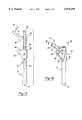
- FIG. 1is an exploded perspective view of the components of the invention embodied in a preferred modular hip prosthesis, with the components positioned for maximum stem extension;
- FIG. 2is an external top view of the prosthesis of FIG. 1;
- FIG. 3is a longitudinal sectional view of the prosthesis of FIG. 2, taken along the lines 3--3;
- FIG. 4is a perspective view of the hip prosthesis of FIG. 1, shown fully assembled with the stem component in its fully extended position;
- FIG. 5is an exploded perspective view of the components of the invention embodied in a preferred modular hip prosthesis, with the components positioned for minimal stem extension;
- FIG. 6is an external top view of the prosthesis of FIG. 5;
- FIG. 7is a longitudinal sectional view of the prosthesis of FIG. 5, taken along the lines 7--7 of FIG. 6;
- FIG. 8is a perspective view of the hip prosthesis of FIG. 1, shown fully assembled with the stem component in its minimally extended position;
- FIG. 9is a longitudinal sectional view of the prosthesis of FIG. 8, taken along the lines 9--9;
- FIG. 10is a side view of the hip prosthesis of FIG. 1, shown fully assembled with the stem component in its minimally extended position;
- FIG. 11is a transverse sectional view of the hip prosthesis of FIG. 8, taken along the lines 11--11, showing the preferred expanded collet mechanism of the invention located on the stem;
- FIG. 12is a side view of the preferred hip prosthesis of the invention, shown in an assembled state with the stem in its maximally-extended position and the trochanteric module rotated to an alternative conformation;
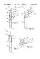
- FIG. 13is an exploded perspective view of the components of the invention embodied in a preferred modular hip prosthesis, with the expanding collet mechanism located on the neck;
- FIG. 14is a longitudinal sectional exploded view of the prosthesis of FIG. 13, taken along the lines 14--14;
- FIG. 15is a side of the hip prosthesis of FIG. 13, shown fully assembled with the stem component in its maximally extended position;
- FIG. 16is a top plan sectional view of the prosthesis of FIG. 15, taken along the lines 16--16;
- FIG. 17is a perspective view of the hip prosthesis of FIG. 13, shown fully assembled with the stem component in its maximally extended position;
- FIG. 18is a longitudinal sectional view of the prosthesis of FIG. 17, taken along the lines 18--18;
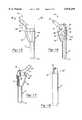
- FIG. 19is an exploded perspective view of the components of the invention embodied in a preferred modular tibial prosthesis, with the expanding collet mechanism located on the stem;
- FIG. 20is a longitudinal sectional view of the tibial prosthesis of FIG. 19, taken along the lines 20--20;
- FIG. 21is a perspective view of the tibial prosthesis of FIG. 19, shown fully assembled with the stem component in its minimally extended position;
- FIG. 22is a perspective view of the tibial prosthesis of FIG. 19, shown fully assembled with the stem component in its maximally extended position;
- FIG. 23is a side view of the prosthesis of FIG. 19, shown in an assembled state with the stem in its maximally-extended position and its transition module proximally abutting the distal surface of the tray;
- FIG. 24is an external top view of the tibial prosthesis of FIG. 23;
- FIG. 25is a longitudinal sectional view of the tibial prosthesis of FIG. 23, taken along the lines 7--7 of FIG. 24;
- FIG. 26is a side view of the prosthesis of FIG. 19, shown in, an assembled state with the stem in its minimally-extended position and its transition module spaced from the distal surface of the tray;
- FIG. 27is an external top view of the tibial prosthesis of FIG. 26.
- FIG. 28is a longitudinal sectional view of the tibial prosthesis of FIG. 26, taken along the lines 28--28 of FIG. 27.
- an implantable modular orthopedic prosthesisin this case a hip prosthesis, generally shown at 10, which is comprised of multiple components.
- a first componentis an elongated stem, generally shown at 12, with a free distal end 14, configured to be situated within the intramedullary canal of a patient's bone (not shown), and an opposite end, generally indicated at 16, having an articulating portion, preferably a Morse-tapered connecting member, such as the frusto-conical bore 18.
- a second componentis a neck, generally shown at 20, which has another articulating portion, preferably a complementary Morse-tapered connector such as the tapered post 22, which is matingly engageable with the tapered bore 18 of the stem 12.
- a third componentis a trochanteric module, generally indicated at 24 having a contoured body 26 adapted for implantation into the resected proximal femur of a patient.
- a linearly-extruded channel 28is formed through the module 24, along an axis A (FIG. 1) generally coincident with the longitudinal axis of the stem 12, with an internal surface 30.
- the articulating portions 18,22are adjustably received within the channel 28, such that the module 24 can be axially moved along axis A relative to stem 12 and neck 20 to adjust the distance between the module and the neck and stem, respectively.
- At least one of the componentsis radially-expansible, preferably by means of the expanding collet mechanism 32 to pressure lock against the internal surface 30 of the channel 28 in a selected position and arrest the first (stem 12), second (neck 20) and third (module 24) components together as the articulating portions, i.e., tapered bore 18 and post 22, are fully engaged with one another.
- the tapered bore 18 and collet 32are shown in FIG. 12 as being located on the stem 12, the location of these elements may be reversed so that they are on the neck, as will be described hereinafter with reference to FIGS. 13-18.
- the hip prosthesis 10further comprises a tensioning member, generally indicated at 34, operatively connecting the stem 12 and neck 20, to urge the articulating Morse-tapered bore 18 and post 22 together and affix all three components 12, 20, 24 of the prosthesis 10 together in a desired relative conformation.
- a tensioning membergenerally indicated at 34, operatively connecting the stem 12 and neck 20, to urge the articulating Morse-tapered bore 18 and post 22 together and affix all three components 12, 20, 24 of the prosthesis 10 together in a desired relative conformation.
- the tensioning memberpreferably consists of a locking bolt 34 having an elongated shaft 36 with a driven end 38 and a threaded end 40 which passes distally through an opening 42 formed in the neck 20, thence through the tapered post 18 and bore 22 to threadedly engage a tapped aperture 44 in the stem 12.
- the bolt 34could alternatively be passed through an opening optionally formed in the distal end 14 of the stem 12 (not shown) and continuing proximally to engage a threaded aperture in the neck (not shown), as will be appreciated by those skilled in the art.
- the linearly extruded channel 28preferably has a circular cross section, e.g., a cylindrical bore, allowing infinitely variable rotational adjustment of the stem 12 and neck 20 relative to one another, and allowing proximal-distal adjustment of these components within the channel 28.
- the channel 28may alternatively have a polygonal cross section or a star shape (not shown) while the articulating portions could have corresponding shapes which would be respectively indexable relative to the channel in a finite selection of rotational alignments, rather than the infinite rotational adjustability afforded by the Morse-tapered connection described herein.
- Having a square shaped channel (not shown), for example,would allow for 4 orthogonal relative rotations of the neck 20 and stem 12, while the multi-point star shape would allow for multiple rotations of the neck and stem.
- the linearly extruded cut of the channel 28also allows for the independent insertion, rotation and removal of the stem 12 without removing the anatomically press fit trochanteric module 24, once implanted. Though inserting the stem 12 from the proximal end of the neck has its advantages, inserting the stem from the distal direction proximally into the neck, prior to insertion into the femoral bone allows for greater mechanical stability and variable design flexibility.
- the body 26 of trochanteric module 24has a proximal shoulder 46 which abuts a stop 48 formed on the neck 20, limiting the range of axially adjustable telescoping movement of the surrounding trochanteric module 24 relative to the neck and stem 12, prior to full engagement of the articulating bore 18 and post 22 by tightening of the bolt 34.
- Module 24has a rounded triangular cross section, adjacent the proximal shoulder 46, the area of which reduces distally, shown, e. g., in FIGS. 10-11.
- the neck 20is equipped with an integral, angulated member 21 with a further Morse-tapered post 23 for attachment of a conventional ball (not shown).
- the prosthesis 10is shown with the stem 12 in its maximally extended position, that is, the shoulder 46 abuts the stop 48 with the components 12, 20, 24 affixed together.
- the collet 32is fully constrained within the channel 28, as shown in FIG. 4 and also in FIG. 5 where the collet 32 is actuated within channel 28 to pressure-lock against internal surface 30 in a selected location such that the shoulder 46 is axially spaced from the distal stop 48.
- a patientcan be fitted with a fixed size of prosthetic components, then the sized components adapted to either increase (FIG. 4) or decrease (FIG. 5) the effective length of the stem 12, depending upon the patients anatomy, without resort to a more complex assortment of intermediate sizes of trial implants and prosthetic components.
- FIG. 11shows the collet 32 expanded radially against the internal surface 30 in the direction of arrows 50, in the manner described above, i. e., by actuation of the locking bolt 34.
- a hip prosthesis 10 of the present inventionis shown having the trochanteric module 24 rotationally adjusted so that the portion of the body 26 which forms a transverse triangular faceted shaped member 52 forms a complex angle with the axis B of the ball post 23 and the axis A of the stem 12.
- FIGS. 13-18show a prosthesis 10 with an alternative juxtaposition of the collet 32 and Morse-tapered bore 18 situated on the neck 20 rather than stem 12, and the tapered post 22 located on the proximal articulating portion of the stem 12.
- the prosthesis 10like the embodiment of FIGS. 1-12, may be assembled either with stem 12 in a minimally extended (FIGS. 15-16) or maximally extended (FIGS. 17-18) conformation.
- Morse tapered connectionsTraditional fixation mechanisms for modular implants typically use Morse tapered connections.
- the Morse taperis designed to withstand compressive forces and rotational torque, but is not particularly well suited for tension forces and bending moments. It can be shown that bending moments induced on a Morse-tapered connection, where the independent components have dissimilar moments of inertia, can cause surface micro motion at the connection and hence wear, wear debris and eventual failure of the connection.
- the fully contained radial expansion mechanism described herein, with reference to collet 32transfers the bending moments induced on the implanted prosthesis 10, due to day to day activities, away from the articulating portions which connect the stem 12 and neck 20 components, toward the strongest portion of the prosthetic joint. Thus the expansion mechanism experiences much less stress than the interface of traditional taper connection modular hip stems.
- the surgical procedure for preparing the patient to be implanted with the prosthesis 10could be chosen from a variety of generally recognized methods and instrumentation, however, an example of a suitable technique is given in the aforementioned U.S. Pat. No. 5,201,882 to Paxson, the entire disclosure of which is expressly incorporated by reference herein and relied upon.
- the prosthesis 10is a modular connection system for use in total joint arthroplasty. Therefore, the rotational and linear extension mechanism of the invention can readily be applied to knee, shoulder and hip joint replacement components each having similar characteristics and functional advantages as it relates to adjustable bone fixation.
- a tibial prosthesis for use in total knee arthroplastywill be described below.
- an implantable modular tibial prosthesis 110is depicted, with an elongated stem 112 having a free distal end 114, configured to be situated within the intramedullary canal of a patient's bone, and an opposite end 116 having preferably a Morse-tapered bore 118.
- a tibial tray 120having another articulating portion in the form of a Morse-tapered post 122 matingly engageable with the tapered bore 118 of the stem 112, for attaching the tray 120 and stem 112 together in a selected fixed rotational conformation.
- a transition modulehas a body 126 with a linearly-extruded channel 128 having an internal surface 130, through which the articulating tapered bore 118 and post 122 of the stem 112 and tray 120, respectively, are telescopically received.
- the stem 112is radially-expansible by means of an expanding collet mechanism 132 to pressure lock against the internal surface 130 of the channel 128 in a selected location to arrest the stem 112, tray 120 and transition module 124 together in a fixed axial and rotational relationship as the mating articulating connectors 118, 122 are fully engaged with one another.
- a tensioning membersuch as the locking bolt 134, operatively connects the stem 112 and tray 120, to urge the tapered bore 118 and post 122 fully together to affix the tray, stem and transition module together in a desired relative conformation.
- the locking bolt 134has an elongated shaft 136 having a driven end 138 and a threaded end 140 which passes through an opening 142 formed in the tray 120 to threadedly engage a tapped aperture 144 in the stem 112.
- the stem 112 of prosthesis 110has a Morse-tapered bore 118 and the neck 120 has the complementary Morse-tapered post 122, respectively, these elements could be reversed (not shown), similar to the juxtaposition, described above in FIGS. 1-12 versus FIGS. 13-18, for the hip prosthesis 10. That is, and although not shown in the Drawings, the tray 120 could have the radially expansible collet and tapered bore, rather than having them on the stem, to pressure lock against the internal surface of the channel.
- Channel 128 formed in the transition module 124preferably has a circular cross section, e. g., a cylindrical bore, allowing infinitely variable rotational adjustment of the tray and stem relative to one another, and allowing axial adjustment of the transition module relative to the engaged tray and stem.
- the channel 128could have a polygonal cross section and the articulating portions could have corresponding shapes which are respectively indexable relative to the channel in a finite selection of rotational alignments.
- a shoulder 146is formed on the transition module 124 which abuts a stop 148 formed on the tray 120, limiting the range of axially adjustable telescoping movement of the transition module relative to the tray and stem 112 prior to full engagement of the articulating portions 118, 122 thereof.
- the transition module 124Prior to tightening of the tapered bore 118 and post 122 together by turning bolt 134, the transition module 124 can be slid in either the proximal direction, to increase the effective length of the stem 112 by abutment of shoulder 146 with stop 148 (FIGS. 22-25), or distally to decrease the stem length (FIGS. 21 and 26-28) leaving the shoulder 146 spaced from stop 148.
Landscapes
- Health & Medical Sciences (AREA)
- Orthopedic Medicine & Surgery (AREA)
- Heart & Thoracic Surgery (AREA)
- Vascular Medicine (AREA)
- Oral & Maxillofacial Surgery (AREA)
- Transplantation (AREA)
- Engineering & Computer Science (AREA)
- Biomedical Technology (AREA)
- Veterinary Medicine (AREA)
- Cardiology (AREA)
- Life Sciences & Earth Sciences (AREA)
- Animal Behavior & Ethology (AREA)
- General Health & Medical Sciences (AREA)
- Public Health (AREA)
- Physical Education & Sports Medicine (AREA)
- Prostheses (AREA)
Abstract
Description
Claims (26)
Priority Applications (6)
| Application Number | Priority Date | Filing Date | Title |
|---|---|---|---|
| US08/706,406US5876459A (en) | 1996-08-30 | 1996-08-30 | Adjustable modular orthopedic implant |
| PCT/US1996/016246WO1998008467A1 (en) | 1996-08-30 | 1996-10-11 | Adjustable modular orthopedic implant |
| AU74374/96AAU7437496A (en) | 1996-08-30 | 1996-10-11 | Adjustable modular orthopedic implant |
| US08/885,674US5906644A (en) | 1996-08-30 | 1997-06-30 | Adjustable modular orthopedic implant |
| AU40927/97AAU4092797A (en) | 1996-08-30 | 1997-08-26 | Adjustable modular orthopedic implant |
| PCT/US1997/015047WO1998008468A1 (en) | 1996-08-30 | 1997-08-26 | Adjustable modular orthopedic implant |
Applications Claiming Priority (1)
| Application Number | Priority Date | Filing Date | Title |
|---|---|---|---|
| US08/706,406US5876459A (en) | 1996-08-30 | 1996-08-30 | Adjustable modular orthopedic implant |
Related Child Applications (1)
| Application Number | Title | Priority Date | Filing Date |
|---|---|---|---|
| US08/885,674Continuation-In-PartUS5906644A (en) | 1996-08-30 | 1997-06-30 | Adjustable modular orthopedic implant |
Publications (1)
| Publication Number | Publication Date |
|---|---|
| US5876459Atrue US5876459A (en) | 1999-03-02 |
Family
ID=24837415
Family Applications (1)
| Application Number | Title | Priority Date | Filing Date |
|---|---|---|---|
| US08/706,406Expired - LifetimeUS5876459A (en) | 1996-08-30 | 1996-08-30 | Adjustable modular orthopedic implant |
Country Status (1)
| Country | Link |
|---|---|
| US (1) | US5876459A (en) |
Cited By (127)
| Publication number | Priority date | Publication date | Assignee | Title |
|---|---|---|---|---|
| US5976188A (en)* | 1997-10-21 | 1999-11-02 | Johnson & Johnson Professional, Inc. | Modular prosthesis system with hybrid fixation |
| US6193759B1 (en)* | 1997-03-26 | 2001-02-27 | Depuy Orthopaedics, Inc. | Modular long stem hip trial |
| US6200350B1 (en) | 1999-10-01 | 2001-03-13 | Medidea, Llc | Anti-impingement femoral prostheses |
| US6245112B1 (en) | 2000-02-29 | 2001-06-12 | Hammill Manufacturing Co. | Joint prosthesis variable flexibility |
| US6264699B1 (en)* | 1998-11-23 | 2001-07-24 | Depuy Orthopaedics, Inc. | Modular stem and sleeve prosthesis |
| US6290726B1 (en) | 2000-01-30 | 2001-09-18 | Diamicron, Inc. | Prosthetic hip joint having sintered polycrystalline diamond compact articulation surfaces |
| US6299648B1 (en) | 2000-03-17 | 2001-10-09 | Hammill Manufacturing Co. | Locking hip prosthesis |
| US6319286B1 (en) | 2000-03-13 | 2001-11-20 | Exactech, Inc | Modular hip prosthesis |
| US6355068B1 (en) | 2001-06-07 | 2002-03-12 | Hammill Manufacturing Co. | Sight gauge modular joint and method |
| US6398815B1 (en) | 2000-01-30 | 2002-06-04 | Diamicron, Inc. | Prosthetic joint having at least one superhard articulation surface |
| US6410877B1 (en) | 2000-01-30 | 2002-06-25 | Diamicron, Inc. | Methods for shaping and finishing prosthetic joint components including polycrystalline diamond compacts |
| US6425922B1 (en) | 2000-01-30 | 2002-07-30 | Diamicron, Inc. | Prosthetic hip joint having at least one sintered polycrystalline diamond compact articulation surface |
| US6428578B2 (en)* | 1998-03-18 | 2002-08-06 | Sct Incorporated | Modular prosthesis and connector therefor |
| US6440171B1 (en) | 2001-02-27 | 2002-08-27 | Hammill Manuf. Co. | Double D key locking prosthesis |
| US6488715B1 (en) | 2000-01-30 | 2002-12-03 | Diamicron, Inc. | Diamond-surfaced cup for use in a prosthetic joint |
| EP1205161A3 (en)* | 2000-11-08 | 2002-12-04 | Depuy Orthopaedics, Inc. | Self-locking modular prosthesis having taper feature and associated method |
| US6494918B1 (en) | 2000-01-30 | 2002-12-17 | Diamicron, Inc. | Component for a prosthetic joint having a diamond load bearing and articulation surface |
| US20030074079A1 (en)* | 1998-04-14 | 2003-04-17 | Osteoimplant Technology, Inc. | Differential porosity prosthetic hip system |
| US20030073997A1 (en)* | 2001-10-17 | 2003-04-17 | Doubler Robert L. | Split ring bone screw for a spinal fixation system |
| US6596225B1 (en) | 2000-01-31 | 2003-07-22 | Diamicron, Inc. | Methods for manufacturing a diamond prosthetic joint component |
| US6623485B2 (en) | 2001-10-17 | 2003-09-23 | Hammill Manufacturing Company | Split ring bone screw for a spinal fixation system |
| US20030191533A1 (en)* | 2000-01-30 | 2003-10-09 | Diamicron, Inc. | Articulating diamond-surfaced spinal implants |
| US20030204268A1 (en)* | 2002-04-25 | 2003-10-30 | Medicinelodge, Inc. | Binary attachment mechanism and method for a modular prosthesis |
| US20030204266A1 (en)* | 2002-04-25 | 2003-10-30 | Medicinelodge, Inc. | Modular prosthesis for replacing bone and method |
| WO2003094803A1 (en)* | 2002-05-09 | 2003-11-20 | Hayes Medical, Inc. | System for trial implantation of a femoral hip prosthesis |
| US6663670B2 (en) | 2002-01-18 | 2003-12-16 | Depuy Orthopaedics, Inc. | Adjustable long bone prosthesis |
| US6669728B2 (en) | 2000-07-20 | 2003-12-30 | Depuy Products, Inc. | Modular connection for orthopedic component |
| US6676704B1 (en) | 1994-08-12 | 2004-01-13 | Diamicron, Inc. | Prosthetic joint component having at least one sintered polycrystalline diamond compact articulation surface and substrate surface topographical features in said polycrystalline diamond compact |
| US20040010319A1 (en)* | 1998-04-14 | 2004-01-15 | Osteoimplant Technology Inc. | Intrinsic stability in a total hip stem |
| US6692530B2 (en) | 2001-10-17 | 2004-02-17 | Hammill Manufacturing Co. | Split sleeve modular joint |
| US6702854B1 (en) | 1999-06-01 | 2004-03-09 | Apex Surgical, Llc | Implantable joint prosthesis |
| US6709463B1 (en) | 2000-01-30 | 2004-03-23 | Diamicron, Inc. | Prosthetic joint component having at least one solid polycrystalline diamond component |
| US20040064186A1 (en)* | 2002-09-30 | 2004-04-01 | Mccleary Larry G. | Modular trial mechanism |
| US6716250B2 (en) | 2001-11-05 | 2004-04-06 | Ramin Ganjianpour | Modular femoral prosthesis |
| US6746487B2 (en)* | 2002-03-06 | 2004-06-08 | Smith & Nephew, Inc. | Intramedullary trial fixation device |
| US20040117024A1 (en)* | 2002-12-13 | 2004-06-17 | Gerbec Daniel E. | Modular implant for joint reconstruction and method of use |
| US20040122439A1 (en)* | 2002-12-20 | 2004-06-24 | Dwyer Kimberly A. | Adjustable biomechanical templating & resection instrument and associated method |
| US20040122440A1 (en)* | 2002-12-20 | 2004-06-24 | Daniels David W. | Instrument and associated method of trialing for modular hip stems |
| US20040122437A1 (en)* | 2002-12-20 | 2004-06-24 | Dwyer Kimberly A. | Alignment device for modular implants and method |
| US6793681B1 (en) | 1994-08-12 | 2004-09-21 | Diamicron, Inc. | Prosthetic hip joint having a polycrystalline diamond articulation surface and a plurality of substrate layers |
| US20040254646A1 (en)* | 2003-06-16 | 2004-12-16 | Stone Kevin T. | Provisional coupling mechanism |
| US20040267373A1 (en)* | 2003-06-25 | 2004-12-30 | Dwyer Kimberly Ann | Assembly tool for modular implants and associated method |
| US20040267267A1 (en)* | 2003-06-25 | 2004-12-30 | Daniels David Wayne | Non-linear reamer for bone preparation and associated method |
| US20050033444A1 (en)* | 2003-06-25 | 2005-02-10 | Jones Michael C. | Assembly tool for modular implants and associated method |
| US20050043811A1 (en)* | 2003-08-22 | 2005-02-24 | Doubler Robert L. | Welded hip prosthesis |
| US6866683B2 (en) | 2002-12-13 | 2005-03-15 | Medicine Lodge, Inc. | Modular implant for joint reconstruction and method of use |
| US20050075735A1 (en)* | 2000-04-10 | 2005-04-07 | Berelsman Brian K. | Method and apparatus for adjusting height and angle for a radial head |
| US20050101956A1 (en)* | 2003-11-10 | 2005-05-12 | Simonson Peter M. | Artificial facet joint and method |
| US20050101953A1 (en)* | 2003-11-10 | 2005-05-12 | Simonson Peter M. | Artificial facet joint and method |
| US6902583B2 (en) | 2002-04-25 | 2005-06-07 | Medicinelodge, Inc. | Tripartite attachment mechanism and method for a modular prosthesis |
| US20050125067A1 (en)* | 2003-12-08 | 2005-06-09 | Sweeney Patrick J. | Modular cannulated total joint prosthesis |
| US6913623B1 (en) | 2000-08-15 | 2005-07-05 | Centerpulse Orthopedics, Inc. | Two piecefused femoral hip stem |
| US20050158200A1 (en)* | 1994-08-12 | 2005-07-21 | Diamicron, Inc. | Use of CoCrMo to augment biocompatibility in polycrystalline diamond compacts |
| US20050165493A1 (en)* | 2004-01-22 | 2005-07-28 | Ries Michael D. | Femoral hip prosthesis and method of implantation |
| US20050203629A1 (en)* | 2004-02-26 | 2005-09-15 | George Cipolletti | Modular knee prosthesis |
| US20050203634A1 (en)* | 2004-03-09 | 2005-09-15 | Howmedica Osteonics Corp. | Modular prosthesis kits |
| US20050261778A1 (en)* | 2004-05-18 | 2005-11-24 | Lev Zelener | Hip prosthesis |
| US20050277927A1 (en)* | 2004-06-14 | 2005-12-15 | Guenther Kevin V | Fastening system for spinal stabilization system |
| US20060106463A1 (en)* | 2004-10-21 | 2006-05-18 | Biomet Manufacturing Corp. | Prosthesis |
| US7074224B2 (en) | 2003-06-25 | 2006-07-11 | Depuy Products, Inc. | Modular tapered reamer for bone preparation and associated method |
| US20060167555A1 (en)* | 2004-12-17 | 2006-07-27 | Heck Robert K | Modular diaphyseal and collar implant |
| US20060167560A1 (en)* | 2004-12-17 | 2006-07-27 | Heck Robert K | Modular implant system and method with diaphyseal implant and adapter |
| US20060167554A1 (en)* | 2004-12-17 | 2006-07-27 | Heck Robert K | Modular implant system and method with diaphyseal implant |
| US20060271199A1 (en)* | 2005-05-20 | 2006-11-30 | Johnson Lanny L | Navigational markers in implants |
| US20070043447A1 (en)* | 2003-10-09 | 2007-02-22 | Cheal Edward J | Tapered joint prosthesis |
| US20070050039A1 (en)* | 2005-08-30 | 2007-03-01 | Dietz Terry L | Orthopaedic implant, stem and associated method |
| US7235106B2 (en) | 2002-12-20 | 2007-06-26 | Depuy Products, Inc. | Modular hip stems and associated method of trialing |
| US20080125867A1 (en)* | 2006-11-28 | 2008-05-29 | Depuy Products, Inc. | Modular proximal body trial |
| US20080161811A1 (en)* | 2006-09-29 | 2008-07-03 | Depuy Products, Inc. | Proximal reamer |
| US7396501B2 (en) | 1994-08-12 | 2008-07-08 | Diamicron, Inc. | Use of gradient layers and stress modifiers to fabricate composite constructs |
| US20080195220A1 (en)* | 2000-01-30 | 2008-08-14 | Diamicron, Inc. | Prosthetic hip joint having polycrystalline diamond articulation surfaces and at least one solid polycrystalline diamond compact |
| US20080255560A1 (en)* | 2004-05-21 | 2008-10-16 | Myers Surgical Solutions, Llc | Fracture Fixation and Site Stabilization System |
| US20080281430A1 (en)* | 2005-02-22 | 2008-11-13 | Kelman David C | Long Sleeves for Use with Stems |
| JP2008279253A (en)* | 2007-05-08 | 2008-11-20 | Zimmer Inc | Modular prosthetic component |
| US7455695B2 (en) | 2004-06-28 | 2008-11-25 | Depuy Products, Inc. | Modular prosthesis and locking nut therefor |
| EP2008617A2 (en) | 2005-12-05 | 2008-12-31 | Medicinelodge, Inc. | Modular progressive implant for a joint articulation surface |
| US20090112216A1 (en)* | 2007-10-30 | 2009-04-30 | Leisinger Steven R | Taper disengagement tool |
| US7608112B1 (en)* | 2004-09-13 | 2009-10-27 | Howmedica Osteonics Corp. | Hip arthroplasty trialing apparatus and method |
| US20100082031A1 (en)* | 2008-09-30 | 2010-04-01 | Sackett Samuel G | Minimally invasive bone miller apparatus |
| US7708764B2 (en) | 2003-11-10 | 2010-05-04 | Simonson Peter M | Method for creating an artificial facet |
| US20100222891A1 (en)* | 2003-11-18 | 2010-09-02 | Depuy Products, Inc. | Modular implant system with fully porous coated sleeve |
| US20100241236A1 (en)* | 2000-04-10 | 2010-09-23 | Biomet Manufacturing Corp. | Modular Radial Head Prosthesis |
| US20100286696A1 (en)* | 2003-12-30 | 2010-11-11 | Depuy Products, Inc. | Minimally Invasive Bone Miller Apparatus |
| US7857858B2 (en) | 2002-04-25 | 2010-12-28 | Zimmer Technology, Inc. | Modular bone implant, tool, and method |
| US20100331992A1 (en)* | 2006-12-07 | 2010-12-30 | Anatol Podolsky | Method and apparatus for total hip replacement |
| US7901436B2 (en) | 2003-09-04 | 2011-03-08 | Zimmer Spine S.A.S. | Spinal implant |
| US20110202141A1 (en)* | 2010-02-18 | 2011-08-18 | Biomet Manufacturing Corp. | Method and apparatus for augmenting bone defects |
| EP2359775A1 (en)* | 2002-02-20 | 2011-08-24 | Zimmer, Inc. | Knee arthroplasty prosthesis and method |
| US8105385B2 (en) | 2001-01-23 | 2012-01-31 | Depuy Products, Inc. | Procedure for the treatment of cuff tear arthropathy |
| US8157869B2 (en) | 2007-01-10 | 2012-04-17 | Biomet Manufacturing Corp. | Knee joint prosthesis system and method for implantation |
| US8163028B2 (en) | 2007-01-10 | 2012-04-24 | Biomet Manufacturing Corp. | Knee joint prosthesis system and method for implantation |
| US8187280B2 (en) | 2007-10-10 | 2012-05-29 | Biomet Manufacturing Corp. | Knee joint prosthesis system and method for implantation |
| US20120245646A1 (en)* | 2011-03-25 | 2012-09-27 | Gustilo Ramon B | Bone compactor |
| US8328873B2 (en) | 2007-01-10 | 2012-12-11 | Biomet Manufacturing Corp. | Knee joint prosthesis system and method for implantation |
| US8518050B2 (en) | 2007-10-31 | 2013-08-27 | DePuy Synthes Products, LLC | Modular taper assembly device |
| US8533921B2 (en) | 2010-06-15 | 2013-09-17 | DePuy Synthes Products, LLC | Spiral assembly tool |
| US8535382B2 (en) | 2000-04-10 | 2013-09-17 | Biomet Manufacturing, Llc | Modular radial head prostheses |
| US8562616B2 (en) | 2007-10-10 | 2013-10-22 | Biomet Manufacturing, Llc | Knee joint prosthesis system and method for implantation |
| US8579985B2 (en) | 2006-12-07 | 2013-11-12 | Ihip Surgical, Llc | Method and apparatus for hip replacement |
| US20130310947A1 (en)* | 2011-02-01 | 2013-11-21 | Adler Ortho S.R.L. | Femoral stem for hip prosthesis |
| US8617250B2 (en) | 2011-06-17 | 2013-12-31 | Biomet Manufacturing, Llc | Revision knee tibial locking mechanism |
| US8696758B2 (en) | 2011-04-06 | 2014-04-15 | DePuy Synthes Products, LLC | Revision hip prosthesis having an implantable distal stem component |
| WO2014183799A1 (en) | 2013-05-17 | 2014-11-20 | Brainlab Ag | Adjustable endoprosthesis |
| US8961516B2 (en) | 2005-05-18 | 2015-02-24 | Sonoma Orthopedic Products, Inc. | Straight intramedullary fracture fixation devices and methods |
| US8961612B2 (en) | 2012-08-30 | 2015-02-24 | Biomet Manufacturing, Llc | Knee component having orbital interface boss |
| US8974540B2 (en) | 2006-12-07 | 2015-03-10 | Ihip Surgical, Llc | Method and apparatus for attachment in a modular hip replacement or fracture fixation device |
| US8998919B2 (en) | 2003-06-25 | 2015-04-07 | DePuy Synthes Products, LLC | Assembly tool for modular implants, kit and associated method |
| US8998996B2 (en) | 2012-09-20 | 2015-04-07 | Depuy (Ireland) | Knee prosthesis system with standard and distal offset joint line |
| US9060820B2 (en) | 2005-05-18 | 2015-06-23 | Sonoma Orthopedic Products, Inc. | Segmented intramedullary fracture fixation devices and methods |
| US20150190233A1 (en)* | 2012-07-26 | 2015-07-09 | Waldemar Link Gmbh & Co. Kg | Plug-on module for a long shaft prosthesis |
| US9095452B2 (en) | 2010-09-01 | 2015-08-04 | DePuy Synthes Products, Inc. | Disassembly tool |
| US9155574B2 (en) | 2006-05-17 | 2015-10-13 | Sonoma Orthopedic Products, Inc. | Bone fixation device, tools and methods |
| US9259250B2 (en) | 2006-11-22 | 2016-02-16 | Sonoma Orthopedic Products, Inc. | Fracture fixation device, tools and methods |
| US9320603B2 (en) | 2012-09-20 | 2016-04-26 | Depuy (Ireland) | Surgical instrument system with multiple lengths of broaches sharing a common geometry |
| US9532879B2 (en) | 2012-09-20 | 2017-01-03 | Depuy Ireland Unlimited Company | Femoral knee prosthesis system with augments and multiple lengths of sleeves sharing a common geometry |
| US9597203B2 (en)* | 2015-03-25 | 2017-03-21 | Tornier, Inc. | Modular humeral implant |
| US9770278B2 (en) | 2014-01-17 | 2017-09-26 | Arthrex, Inc. | Dual tip guide wire |
| US9814499B2 (en) | 2014-09-30 | 2017-11-14 | Arthrex, Inc. | Intramedullary fracture fixation devices and methods |
| TWI634881B (en)* | 2015-04-21 | 2018-09-11 | 寶楠生技股份有限公司 | Femoral stem with cushion |
| US20180271664A1 (en)* | 2015-12-11 | 2018-09-27 | Aesculap Ag | Artificial joint implant and hip joint endoprosthesis |
| US10813769B2 (en) | 2018-07-24 | 2020-10-27 | DePuy Synthes Products, Inc. | Baseplate of a modular shoulder joint prosthesis and related methods for implanting the same |
| US11173050B2 (en)* | 2019-02-22 | 2021-11-16 | Howmedica Osteonics Corp. | Modular femoral trialing system with temporary locking |
| US11202713B2 (en) | 2019-02-22 | 2021-12-21 | Howmedica Osteonics Corp. | Modular femoral trialing system having adjustable height |
| US11311392B2 (en) | 2019-02-22 | 2022-04-26 | Howmedica Osteonics Corp. | Modular femoral trialing system permitting relative movement |
| US11826267B2 (en) | 2017-04-12 | 2023-11-28 | Depuy Ireland Unlimited Company | Femoral trialling kit and assembly |
| WO2024111005A1 (en)* | 2022-11-22 | 2024-05-30 | Limacorporate S.P.A. | Prosthetic trial device |
| US12127955B2 (en) | 2021-04-29 | 2024-10-29 | Depuy Ireland Unlimited Company | Trial component and method |
Citations (12)
| Publication number | Priority date | Publication date | Assignee | Title |
|---|---|---|---|---|
| US3846846A (en)* | 1972-09-28 | 1974-11-12 | Fischer Artur | Hip joint prosthesis |
| US4502160A (en)* | 1983-10-27 | 1985-03-05 | Dow Corning Wright | Adjustable length prosthetic joint implant |
| US4520511A (en)* | 1981-10-26 | 1985-06-04 | Paribelli Gianezio | Hip prosthesis with expanding femoral component |
| US4995883A (en)* | 1989-02-08 | 1991-02-26 | Smith & Nephew Richards Inc. | Modular hip prosthesis |
| US5002578A (en)* | 1990-05-04 | 1991-03-26 | Venus Corporation | Modular hip stem prosthesis apparatus and method |
| US5035712A (en)* | 1989-06-16 | 1991-07-30 | Ordev B.V. | Self-adjusting prosthesis attachment |
| WO1991011155A1 (en)* | 1990-01-23 | 1991-08-08 | Orthovations, Inc. | Method and apparatus for expanding a prosthesis |
| US5507817A (en)* | 1994-02-22 | 1996-04-16 | Kirschner Medical Corporation | Modular humeral prosthesis for reconstruction of the humerus |
| US5507830A (en)* | 1989-02-08 | 1996-04-16 | Smith & Nephew Richards Inc. | Modular hip prosthesis |
| US5569263A (en)* | 1995-01-12 | 1996-10-29 | Orthopaedic Innovations, Inc. | Adjustable provisional articulating device |
| US5653765A (en)* | 1994-07-01 | 1997-08-05 | Ortho Development Corporation | Modular prosthesis |
| US5658349A (en)* | 1991-07-29 | 1997-08-19 | Joint Medical Products Corporation | Prosthetic joint system for bone replacement |
- 1996
- 1996-08-30USUS08/706,406patent/US5876459A/ennot_activeExpired - Lifetime
Patent Citations (12)
| Publication number | Priority date | Publication date | Assignee | Title |
|---|---|---|---|---|
| US3846846A (en)* | 1972-09-28 | 1974-11-12 | Fischer Artur | Hip joint prosthesis |
| US4520511A (en)* | 1981-10-26 | 1985-06-04 | Paribelli Gianezio | Hip prosthesis with expanding femoral component |
| US4502160A (en)* | 1983-10-27 | 1985-03-05 | Dow Corning Wright | Adjustable length prosthetic joint implant |
| US4995883A (en)* | 1989-02-08 | 1991-02-26 | Smith & Nephew Richards Inc. | Modular hip prosthesis |
| US5507830A (en)* | 1989-02-08 | 1996-04-16 | Smith & Nephew Richards Inc. | Modular hip prosthesis |
| US5035712A (en)* | 1989-06-16 | 1991-07-30 | Ordev B.V. | Self-adjusting prosthesis attachment |
| WO1991011155A1 (en)* | 1990-01-23 | 1991-08-08 | Orthovations, Inc. | Method and apparatus for expanding a prosthesis |
| US5002578A (en)* | 1990-05-04 | 1991-03-26 | Venus Corporation | Modular hip stem prosthesis apparatus and method |
| US5658349A (en)* | 1991-07-29 | 1997-08-19 | Joint Medical Products Corporation | Prosthetic joint system for bone replacement |
| US5507817A (en)* | 1994-02-22 | 1996-04-16 | Kirschner Medical Corporation | Modular humeral prosthesis for reconstruction of the humerus |
| US5653765A (en)* | 1994-07-01 | 1997-08-05 | Ortho Development Corporation | Modular prosthesis |
| US5569263A (en)* | 1995-01-12 | 1996-10-29 | Orthopaedic Innovations, Inc. | Adjustable provisional articulating device |
Cited By (289)
| Publication number | Priority date | Publication date | Assignee | Title |
|---|---|---|---|---|
| US7077867B1 (en) | 1994-08-12 | 2006-07-18 | Diamicron, Inc. | Prosthetic knee joint having at least one diamond articulation surface |
| US7396501B2 (en) | 1994-08-12 | 2008-07-08 | Diamicron, Inc. | Use of gradient layers and stress modifiers to fabricate composite constructs |
| US6800095B1 (en) | 1994-08-12 | 2004-10-05 | Diamicron, Inc. | Diamond-surfaced femoral head for use in a prosthetic joint |
| US6676704B1 (en) | 1994-08-12 | 2004-01-13 | Diamicron, Inc. | Prosthetic joint component having at least one sintered polycrystalline diamond compact articulation surface and substrate surface topographical features in said polycrystalline diamond compact |
| US20050158200A1 (en)* | 1994-08-12 | 2005-07-21 | Diamicron, Inc. | Use of CoCrMo to augment biocompatibility in polycrystalline diamond compacts |
| US6793681B1 (en) | 1994-08-12 | 2004-09-21 | Diamicron, Inc. | Prosthetic hip joint having a polycrystalline diamond articulation surface and a plurality of substrate layers |
| US7396505B2 (en) | 1994-08-12 | 2008-07-08 | Diamicron, Inc. | Use of CoCrMo to augment biocompatibility in polycrystalline diamond compacts |
| US6193759B1 (en)* | 1997-03-26 | 2001-02-27 | Depuy Orthopaedics, Inc. | Modular long stem hip trial |
| US5976188A (en)* | 1997-10-21 | 1999-11-02 | Johnson & Johnson Professional, Inc. | Modular prosthesis system with hybrid fixation |
| US6699293B2 (en)* | 1998-03-18 | 2004-03-02 | Sct Incorporated | Prosthesis having wedge-shaped body |
| US6428578B2 (en)* | 1998-03-18 | 2002-08-06 | Sct Incorporated | Modular prosthesis and connector therefor |
| US20040010319A1 (en)* | 1998-04-14 | 2004-01-15 | Osteoimplant Technology Inc. | Intrinsic stability in a total hip stem |
| US7323013B2 (en) | 1998-04-14 | 2008-01-29 | Encore Medical Asset Corporation | Differential porosity prosthetic hip system |
| US20030074079A1 (en)* | 1998-04-14 | 2003-04-17 | Osteoimplant Technology, Inc. | Differential porosity prosthetic hip system |
| US20070043448A1 (en)* | 1998-04-14 | 2007-02-22 | Encore Medical Asset Corporation | Intrinsic stability in a total hip stem |
| US6264699B1 (en)* | 1998-11-23 | 2001-07-24 | Depuy Orthopaedics, Inc. | Modular stem and sleeve prosthesis |
| US6702854B1 (en) | 1999-06-01 | 2004-03-09 | Apex Surgical, Llc | Implantable joint prosthesis |
| US7044975B2 (en) | 1999-06-01 | 2006-05-16 | Apex Surgical, Llc | Joint prostheses and components thereof |
| US20020128720A1 (en)* | 1999-10-01 | 2002-09-12 | Masini Michael A. | Anti-impingement femoral prostheses |
| USRE44803E1 (en) | 1999-10-01 | 2014-03-11 | Medidea, Llc | Anti-impingement femoral prostheses |
| US7985261B2 (en) | 1999-10-01 | 2011-07-26 | Medidea, Llc | Anti-impingement femoral prostheses |
| US6200350B1 (en) | 1999-10-01 | 2001-03-13 | Medidea, Llc | Anti-impingement femoral prostheses |
| US6398815B1 (en) | 2000-01-30 | 2002-06-04 | Diamicron, Inc. | Prosthetic joint having at least one superhard articulation surface |
| US6425922B1 (en) | 2000-01-30 | 2002-07-30 | Diamicron, Inc. | Prosthetic hip joint having at least one sintered polycrystalline diamond compact articulation surface |
| US20080215158A1 (en)* | 2000-01-30 | 2008-09-04 | Diamicron, Inc. | Prosthetic hip joint having polycrystalline diamond articulation surfaces and at least one solid polycrystalline diamond compact |
| US6709463B1 (en) | 2000-01-30 | 2004-03-23 | Diamicron, Inc. | Prosthetic joint component having at least one solid polycrystalline diamond component |
| US6610095B1 (en) | 2000-01-30 | 2003-08-26 | Diamicron, Inc. | Prosthetic joint having substrate surface topographical featurers and at least one diamond articulation surface |
| US20080195220A1 (en)* | 2000-01-30 | 2008-08-14 | Diamicron, Inc. | Prosthetic hip joint having polycrystalline diamond articulation surfaces and at least one solid polycrystalline diamond compact |
| US20030191533A1 (en)* | 2000-01-30 | 2003-10-09 | Diamicron, Inc. | Articulating diamond-surfaced spinal implants |
| US6497727B1 (en) | 2000-01-30 | 2002-12-24 | Diamicron, Inc. | Component for use in prosthetic hip, the component having a polycrystalline diamond articulation surface and a plurality of substrate layers |
| US6494918B1 (en) | 2000-01-30 | 2002-12-17 | Diamicron, Inc. | Component for a prosthetic joint having a diamond load bearing and articulation surface |
| US7494507B2 (en) | 2000-01-30 | 2009-02-24 | Diamicron, Inc. | Articulating diamond-surfaced spinal implants |
| US6488715B1 (en) | 2000-01-30 | 2002-12-03 | Diamicron, Inc. | Diamond-surfaced cup for use in a prosthetic joint |
| US6517583B1 (en) | 2000-01-30 | 2003-02-11 | Diamicron, Inc. | Prosthetic hip joint having a polycrystalline diamond compact articulation surface and a counter bearing surface |
| US6410877B1 (en) | 2000-01-30 | 2002-06-25 | Diamicron, Inc. | Methods for shaping and finishing prosthetic joint components including polycrystalline diamond compacts |
| US6402787B1 (en) | 2000-01-30 | 2002-06-11 | Bill J. Pope | Prosthetic hip joint having at least one sintered polycrystalline diamond compact articulation surface and substrate surface topographical features in said polycrystalline diamond compact |
| US6290726B1 (en) | 2000-01-30 | 2001-09-18 | Diamicron, Inc. | Prosthetic hip joint having sintered polycrystalline diamond compact articulation surfaces |
| US6596225B1 (en) | 2000-01-31 | 2003-07-22 | Diamicron, Inc. | Methods for manufacturing a diamond prosthetic joint component |
| US6245112B1 (en) | 2000-02-29 | 2001-06-12 | Hammill Manufacturing Co. | Joint prosthesis variable flexibility |
| US6319286B1 (en) | 2000-03-13 | 2001-11-20 | Exactech, Inc | Modular hip prosthesis |
| US20020038148A1 (en)* | 2000-03-13 | 2002-03-28 | Jose Fernandez | Modular hip prosthesis |
| US6911048B2 (en)* | 2000-03-13 | 2005-06-28 | Exactech, Inc. | Modular hip prosthesis |
| WO2001070140A3 (en)* | 2000-03-17 | 2002-02-28 | Hammill Mfg Co | Locking modular hip prosthesis |
| US6299648B1 (en) | 2000-03-17 | 2001-10-09 | Hammill Manufacturing Co. | Locking hip prosthesis |
| US8366781B2 (en) | 2000-04-10 | 2013-02-05 | Biomet Manufacturing Corp. | Modular prosthesis and use thereof for replacing a radial head |
| US8425615B2 (en) | 2000-04-10 | 2013-04-23 | Biomet Manufacturing Corp. | Method and apparatus for adjusting height and angle for a radial head |
| US20100312349A1 (en)* | 2000-04-10 | 2010-12-09 | Biomet Manufacturing Corp. | Modular prosthesis and use thereof for replacing a radial head |
| US20100262252A1 (en)* | 2000-04-10 | 2010-10-14 | Biomet Manufacturing Corp. | Modular prosthesis and use thereof for replacing a radial head |
| US20100241236A1 (en)* | 2000-04-10 | 2010-09-23 | Biomet Manufacturing Corp. | Modular Radial Head Prosthesis |
| US20110125276A1 (en)* | 2000-04-10 | 2011-05-26 | Biomet Manufacturing Corp. | Modular prosthesis and use thereof for replacing a radial head |
| US20100030339A1 (en)* | 2000-04-10 | 2010-02-04 | Biomet Manufacturing Corp. | Method and apparatus for adjusting height and angle for a radial head |
| US20110144759A1 (en)* | 2000-04-10 | 2011-06-16 | Biomet Manufacturing Corp. | Modular prosthesis and use thereof for replacing a radial head |
| US9439784B2 (en) | 2000-04-10 | 2016-09-13 | Biomet Manufacturing, Llc | Modular radial head prosthesis |
| US9333084B2 (en) | 2000-04-10 | 2016-05-10 | Biomet Manufacturing, Llc | Modular prosthesis and use thereof for replacing a radial head |
| US8110005B2 (en) | 2000-04-10 | 2012-02-07 | Biomet Manufacturing Corp. | Modular prosthesis and use thereof for replacing a radial head |
| US8114163B2 (en) | 2000-04-10 | 2012-02-14 | Biomet Manufacturing Corp. | Method and apparatus for adjusting height and angle for a radial head |
| US8920509B2 (en) | 2000-04-10 | 2014-12-30 | Biomet Manufacturing, Llc | Modular radial head prosthesis |
| US9579208B2 (en) | 2000-04-10 | 2017-02-28 | Biomet Manufacturing, Llc | Modular radial head prosthesis |
| US20050075735A1 (en)* | 2000-04-10 | 2005-04-07 | Berelsman Brian K. | Method and apparatus for adjusting height and angle for a radial head |
| US8535382B2 (en) | 2000-04-10 | 2013-09-17 | Biomet Manufacturing, Llc | Modular radial head prostheses |
| US20130253658A1 (en)* | 2000-07-20 | 2013-09-26 | Depuy Products, Inc. | Modular femoral stem component for a hip joint prosthesis |
| US20070093908A1 (en)* | 2000-07-20 | 2007-04-26 | Despres Alfred S Iii | Modular femoral stem component for a hip joint prosthesis |
| US20050089365A1 (en)* | 2000-07-20 | 2005-04-28 | Despres Alfred S.Iii | Modular connection for orthopedic component |
| US6669728B2 (en) | 2000-07-20 | 2003-12-30 | Depuy Products, Inc. | Modular connection for orthopedic component |
| US7125193B2 (en) | 2000-07-20 | 2006-10-24 | Depuy Products, Inc. | Modular connection for orthopedic component |
| US7097664B2 (en)* | 2000-07-20 | 2006-08-29 | Depuy Products, Inc. | Modular femoral stem component for a hip joint prosthesis |
| US8303668B2 (en)* | 2000-07-20 | 2012-11-06 | Depuy Products, Inc. | Modular femoral stem component for a hip joint prosthesis |
| US6682568B2 (en) | 2000-07-20 | 2004-01-27 | Depuy Products, Inc. | Modular femoral stem component for a hip joint prosthesis |
| US20040243248A1 (en)* | 2000-07-20 | 2004-12-02 | Despres Alfred S. | Modular femoral stem component for a hip joint prosthesis |
| US7537408B2 (en) | 2000-07-20 | 2009-05-26 | Depuy Products, Inc. | Modular connection for orthopedic component |
| US6913623B1 (en) | 2000-08-15 | 2005-07-05 | Centerpulse Orthopedics, Inc. | Two piecefused femoral hip stem |
| US6706072B2 (en) | 2000-11-08 | 2004-03-16 | Depuy Orthopaedics, Inc. | Modular prosthesis having a stem component with a counterbored cavity defined therein and associated method |
| US6723129B2 (en) | 2000-11-08 | 2004-04-20 | Depuy Orthopaedics, Inc. | Self-locking modular prosthesis having taper feature and associated method |
| EP1205161A3 (en)* | 2000-11-08 | 2002-12-04 | Depuy Orthopaedics, Inc. | Self-locking modular prosthesis having taper feature and associated method |
| US7122056B2 (en) | 2000-11-08 | 2006-10-17 | Depuy Orthopaedics, Inc. | Self-locking modular prosthesis |
| AU782374B2 (en)* | 2000-11-08 | 2005-07-21 | Depuy Orthopaedics, Inc. | Self-locking modular prosthesis having taper feature and associated method |
| US9510839B2 (en) | 2001-01-23 | 2016-12-06 | DePuy Synthes Products, Inc. | Procedure for the treatment of cuff tear arthropathy |
| US8105385B2 (en) | 2001-01-23 | 2012-01-31 | Depuy Products, Inc. | Procedure for the treatment of cuff tear arthropathy |
| US6440171B1 (en) | 2001-02-27 | 2002-08-27 | Hammill Manuf. Co. | Double D key locking prosthesis |
| US6355068B1 (en) | 2001-06-07 | 2002-03-12 | Hammill Manufacturing Co. | Sight gauge modular joint and method |
| US6623485B2 (en) | 2001-10-17 | 2003-09-23 | Hammill Manufacturing Company | Split ring bone screw for a spinal fixation system |
| US6692530B2 (en) | 2001-10-17 | 2004-02-17 | Hammill Manufacturing Co. | Split sleeve modular joint |
| US6887242B2 (en) | 2001-10-17 | 2005-05-03 | Ortho Innovations, Llc | Split ring bone screw for a spinal fixation system |
| US20030073997A1 (en)* | 2001-10-17 | 2003-04-17 | Doubler Robert L. | Split ring bone screw for a spinal fixation system |
| US6716250B2 (en) | 2001-11-05 | 2004-04-06 | Ramin Ganjianpour | Modular femoral prosthesis |
| US6663670B2 (en) | 2002-01-18 | 2003-12-16 | Depuy Orthopaedics, Inc. | Adjustable long bone prosthesis |
| US8048163B2 (en) | 2002-02-20 | 2011-11-01 | Zimmer, Inc. | Knee arthroplasty prosthesis |
| US8092546B2 (en) | 2002-02-20 | 2012-01-10 | Zimmer, Inc. | Knee arthroplasty prosthesis |
| US8092545B2 (en) | 2002-02-20 | 2012-01-10 | Zimmer, Inc. | Knee arthroplasty prosthesis method |
| US9072605B2 (en) | 2002-02-20 | 2015-07-07 | Zimmer, Inc. | Knee arthroplasty prosthesis |
| EP2359775A1 (en)* | 2002-02-20 | 2011-08-24 | Zimmer, Inc. | Knee arthroplasty prosthesis and method |
| US6746487B2 (en)* | 2002-03-06 | 2004-06-08 | Smith & Nephew, Inc. | Intramedullary trial fixation device |
| US7857858B2 (en) | 2002-04-25 | 2010-12-28 | Zimmer Technology, Inc. | Modular bone implant, tool, and method |
| US6902583B2 (en) | 2002-04-25 | 2005-06-07 | Medicinelodge, Inc. | Tripartite attachment mechanism and method for a modular prosthesis |
| US8241367B2 (en) | 2002-04-25 | 2012-08-14 | Zimmer, Inc. | Modular bone implant, tool, and method |
| US20110066249A1 (en)* | 2002-04-25 | 2011-03-17 | Zimmer Technology, Inc. | Modular bone implant, tool, and method |
| US6875239B2 (en) | 2002-04-25 | 2005-04-05 | Medicinelodge, Inc. | Modular prosthesis for replacing bone and method |
| US20030204268A1 (en)* | 2002-04-25 | 2003-10-30 | Medicinelodge, Inc. | Binary attachment mechanism and method for a modular prosthesis |
| US20030204266A1 (en)* | 2002-04-25 | 2003-10-30 | Medicinelodge, Inc. | Modular prosthesis for replacing bone and method |
| US20040054419A1 (en)* | 2002-05-09 | 2004-03-18 | Serra Michael A. | System for trial implantation of a femoral hip prosthesis |
| WO2003094803A1 (en)* | 2002-05-09 | 2003-11-20 | Hayes Medical, Inc. | System for trial implantation of a femoral hip prosthesis |
| US7828851B2 (en) | 2002-09-30 | 2010-11-09 | Depuy Products, Inc. | Modular trial mechanism |
| US20040064186A1 (en)* | 2002-09-30 | 2004-04-01 | Mccleary Larry G. | Modular trial mechanism |
| US7273499B2 (en) | 2002-09-30 | 2007-09-25 | Depuy Products, Inc. | Modular trial mechanism |
| US20070299527A1 (en)* | 2002-09-30 | 2007-12-27 | Depuy Products, Inc. | Modular trial mechanism |
| US6887276B2 (en) | 2002-12-13 | 2005-05-03 | Medicine Lodge, Inc | Modular implant for joint reconstruction and method of use |
| US6866683B2 (en) | 2002-12-13 | 2005-03-15 | Medicine Lodge, Inc. | Modular implant for joint reconstruction and method of use |
| US20040117024A1 (en)* | 2002-12-13 | 2004-06-17 | Gerbec Daniel E. | Modular implant for joint reconstruction and method of use |
| US20040122439A1 (en)* | 2002-12-20 | 2004-06-24 | Dwyer Kimberly A. | Adjustable biomechanical templating & resection instrument and associated method |
| US7022141B2 (en) | 2002-12-20 | 2006-04-04 | Depuy Products, Inc. | Alignment device for modular implants and method |
| US8529578B2 (en) | 2002-12-20 | 2013-09-10 | DePuy Synthes Products, LLC | Instrument and associated method of trialing for modular hip stems |
| US20100292806A1 (en)* | 2002-12-20 | 2010-11-18 | Depuy Products, Inc. | Trialing System and Method for Modular Hip Joint Replacement System |
| US20070244566A1 (en)* | 2002-12-20 | 2007-10-18 | Depuy Products, Inc. | Trialing system and method for modular hip joint replacement system |
| US7235106B2 (en) | 2002-12-20 | 2007-06-26 | Depuy Products, Inc. | Modular hip stems and associated method of trialing |
| US7854737B2 (en) | 2002-12-20 | 2010-12-21 | Depuy Products, Inc. | Instrument and associated method of trailing for modular hip stems |
| US20040122437A1 (en)* | 2002-12-20 | 2004-06-24 | Dwyer Kimberly A. | Alignment device for modular implants and method |
| US20040122440A1 (en)* | 2002-12-20 | 2004-06-24 | Daniels David W. | Instrument and associated method of trialing for modular hip stems |
| US7794503B2 (en) | 2002-12-20 | 2010-09-14 | Depuy Products, Inc. | Trialing system and method for modular hip joint replacement system |
| US20110046745A1 (en)* | 2002-12-20 | 2011-02-24 | Depuy Products, Inc. | Instrument and associated method of trialing for modular hip stems |
| US20040254646A1 (en)* | 2003-06-16 | 2004-12-16 | Stone Kevin T. | Provisional coupling mechanism |
| US20050033444A1 (en)* | 2003-06-25 | 2005-02-10 | Jones Michael C. | Assembly tool for modular implants and associated method |
| US20110125154A1 (en)* | 2003-06-25 | 2011-05-26 | Depuy Products, Inc. | Non-linear reamer for bone preparation and associated method |
| US9381097B2 (en) | 2003-06-25 | 2016-07-05 | DePuy Synthes Products, Inc. | Assembly tool for modular implants, kit and associated method |
| US7074224B2 (en) | 2003-06-25 | 2006-07-11 | Depuy Products, Inc. | Modular tapered reamer for bone preparation and associated method |
| US20040267267A1 (en)* | 2003-06-25 | 2004-12-30 | Daniels David Wayne | Non-linear reamer for bone preparation and associated method |
| US8419799B2 (en) | 2003-06-25 | 2013-04-16 | Depuy Products, Inc. | Assembly tool for modular implants and associated method |
| US20080091212A1 (en)* | 2003-06-25 | 2008-04-17 | Depuy Products, Inc. | Assembly tool for modular implants and associated method |
| US7297166B2 (en) | 2003-06-25 | 2007-11-20 | Depuy Products, Inc. | Assembly tool for modular implants and associated method |
| US20070162033A1 (en)* | 2003-06-25 | 2007-07-12 | Daniels David W | Modular tapered reamer for bone preparation and associated method |
| US8998919B2 (en) | 2003-06-25 | 2015-04-07 | DePuy Synthes Products, LLC | Assembly tool for modular implants, kit and associated method |
| US8790346B2 (en) | 2003-06-25 | 2014-07-29 | DePuy Synthes Products, LLC | Modular tapered reamer for bone preparation and associated method |
| US8685036B2 (en) | 2003-06-25 | 2014-04-01 | Michael C. Jones | Assembly tool for modular implants and associated method |
| US7582092B2 (en) | 2003-06-25 | 2009-09-01 | Depuy Products, Inc. | Assembly tool for modular implants and associated method |
| US20040267373A1 (en)* | 2003-06-25 | 2004-12-30 | Dwyer Kimberly Ann | Assembly tool for modular implants and associated method |
| US7033399B2 (en) | 2003-08-22 | 2006-04-25 | Ortho Innovations, Inc. | Welded hip prosthesis |
| US20060052877A9 (en)* | 2003-08-22 | 2006-03-09 | Doubler Robert L | Welded hip prosthesis |
| US20050043811A1 (en)* | 2003-08-22 | 2005-02-24 | Doubler Robert L. | Welded hip prosthesis |
| US8882808B2 (en) | 2003-09-04 | 2014-11-11 | Zimmer Spine S.A.S. | Spinal implant |
| US7901436B2 (en) | 2003-09-04 | 2011-03-08 | Zimmer Spine S.A.S. | Spinal implant |
| US20110152950A1 (en)* | 2003-09-04 | 2011-06-23 | Christian Baccelli | Spinal implant |
| US10182846B2 (en) | 2003-09-04 | 2019-01-22 | Zimmer Spine S.A.S. | Spinal implant |
| US20070043447A1 (en)* | 2003-10-09 | 2007-02-22 | Cheal Edward J | Tapered joint prosthesis |
| US7572297B2 (en) | 2003-10-09 | 2009-08-11 | Omni Life Science, Inc. | Tapered joint prosthesis |
| US7708764B2 (en) | 2003-11-10 | 2010-05-04 | Simonson Peter M | Method for creating an artificial facet |
| US20050101956A1 (en)* | 2003-11-10 | 2005-05-12 | Simonson Peter M. | Artificial facet joint and method |
| US7083622B2 (en) | 2003-11-10 | 2006-08-01 | Simonson Peter M | Artificial facet joint and method |
| US20050101953A1 (en)* | 2003-11-10 | 2005-05-12 | Simonson Peter M. | Artificial facet joint and method |
| US20080262545A1 (en)* | 2003-11-10 | 2008-10-23 | Simonson Peter M | Artificial Facet Joint and Method |
| US20090216279A1 (en)* | 2003-11-10 | 2009-08-27 | Simonson Peter M | Artificial facet joint and method |
| US8142478B2 (en) | 2003-11-10 | 2012-03-27 | Simonson Peter M | Artificial facet joint and method |
| US20100222891A1 (en)* | 2003-11-18 | 2010-09-02 | Depuy Products, Inc. | Modular implant system with fully porous coated sleeve |
| US7799085B2 (en) | 2003-11-18 | 2010-09-21 | Depuy Products, Inc. | Modular implant system with fully porous coated sleeve |
| US7766968B2 (en) | 2003-12-08 | 2010-08-03 | Sweeney Patrick J | Modular cannulated total joint prosthesis |
| US20050125067A1 (en)* | 2003-12-08 | 2005-06-09 | Sweeney Patrick J. | Modular cannulated total joint prosthesis |
| US20100286696A1 (en)* | 2003-12-30 | 2010-11-11 | Depuy Products, Inc. | Minimally Invasive Bone Miller Apparatus |
| US7942879B2 (en) | 2003-12-30 | 2011-05-17 | Depuy Products, Inc. | Minimally invasive bone miller apparatus |
| US7374576B1 (en) | 2004-01-22 | 2008-05-20 | Medicinelodge, Inc | Polyaxial orthopedic fastening apparatus with independent locking modes |
| US7534271B2 (en) | 2004-01-22 | 2009-05-19 | Smith + Nephew | Femoral hip prosthesis and method of implantation |
| US20110004319A1 (en)* | 2004-01-22 | 2011-01-06 | Michael D. Ries | Femoral Hip Prosthesis and Method of Implantation |
| US20090216335A1 (en)* | 2004-01-22 | 2009-08-27 | Smith & Nephew | Femoral Hip Prosthesis and Method of Implantation |
| US20050165493A1 (en)* | 2004-01-22 | 2005-07-28 | Ries Michael D. | Femoral hip prosthesis and method of implantation |
| US8157871B2 (en) | 2004-01-22 | 2012-04-17 | Michael D Ries | Femoral HIP prosthesis and method of implantation |
| US20050203629A1 (en)* | 2004-02-26 | 2005-09-15 | George Cipolletti | Modular knee prosthesis |
| US8277513B2 (en) | 2004-02-26 | 2012-10-02 | Omni Life Science, Inc. | Modular knee prosthesis |
| US20100262253A1 (en)* | 2004-02-26 | 2010-10-14 | Omni Life Science, Inc. | Modular Knee Prosthesis |
| US7753960B2 (en) | 2004-02-26 | 2010-07-13 | Omni Life Science, Inc. | Modular knee prosthesis |
| US7135044B2 (en) | 2004-03-09 | 2006-11-14 | Howmedics Osteonics Corp. | Modular prosthesis kits |
| US20050203634A1 (en)* | 2004-03-09 | 2005-09-15 | Howmedica Osteonics Corp. | Modular prosthesis kits |
| US7211113B2 (en)* | 2004-05-18 | 2007-05-01 | Lev Zelener | Hip prosthesis |
| US20050261778A1 (en)* | 2004-05-18 | 2005-11-24 | Lev Zelener | Hip prosthesis |
| US20080255560A1 (en)* | 2004-05-21 | 2008-10-16 | Myers Surgical Solutions, Llc | Fracture Fixation and Site Stabilization System |
| US20050277927A1 (en)* | 2004-06-14 | 2005-12-15 | Guenther Kevin V | Fastening system for spinal stabilization system |
| US7731736B2 (en) | 2004-06-14 | 2010-06-08 | Zimmer Spine, Inc. | Fastening system for spinal stabilization system |
| US20090076620A1 (en)* | 2004-06-28 | 2009-03-19 | Depuy Products, Inc. | Modular Prosthesis and Locking Nut Therefor |
| US7455695B2 (en) | 2004-06-28 | 2008-11-25 | Depuy Products, Inc. | Modular prosthesis and locking nut therefor |
| US7608112B1 (en)* | 2004-09-13 | 2009-10-27 | Howmedica Osteonics Corp. | Hip arthroplasty trialing apparatus and method |
| US20060106463A1 (en)* | 2004-10-21 | 2006-05-18 | Biomet Manufacturing Corp. | Prosthesis |
| US7914584B2 (en) | 2004-10-21 | 2011-03-29 | Biomet Manufacturing Corp. | Prosthesis system with trunnion and removably coupled head |
| US20060167554A1 (en)* | 2004-12-17 | 2006-07-27 | Heck Robert K | Modular implant system and method with diaphyseal implant |
| US8100982B2 (en) | 2004-12-17 | 2012-01-24 | Depuy Products, Inc. | Modular diaphyseal and collar implant |
| US20060167555A1 (en)* | 2004-12-17 | 2006-07-27 | Heck Robert K | Modular diaphyseal and collar implant |
| US7867282B2 (en) | 2004-12-17 | 2011-01-11 | Depuy Products, Inc. | Modular implant system and method with diaphyseal implant and adapter |
| US7507256B2 (en) | 2004-12-17 | 2009-03-24 | Depuy Products, Inc. | Modular implant system and method with diaphyseal implant |
| US20060167560A1 (en)* | 2004-12-17 | 2006-07-27 | Heck Robert K | Modular implant system and method with diaphyseal implant and adapter |
| US20080281430A1 (en)* | 2005-02-22 | 2008-11-13 | Kelman David C | Long Sleeves for Use with Stems |
| US9060820B2 (en) | 2005-05-18 | 2015-06-23 | Sonoma Orthopedic Products, Inc. | Segmented intramedullary fracture fixation devices and methods |
| US8961516B2 (en) | 2005-05-18 | 2015-02-24 | Sonoma Orthopedic Products, Inc. | Straight intramedullary fracture fixation devices and methods |
| US20060271199A1 (en)* | 2005-05-20 | 2006-11-30 | Johnson Lanny L | Navigational markers in implants |
| US20070050041A1 (en)* | 2005-08-30 | 2007-03-01 | Dietz Terry L | Orthopaedic implant stem component, joint component, and associated kit |
| US20120016488A1 (en)* | 2005-08-30 | 2012-01-19 | Dietz Terry L | Orthopaedic implant kit, orthopaedic surgery kit and associated method |
| US20070050042A1 (en)* | 2005-08-30 | 2007-03-01 | Dietz Terry L | Orthopaedic implant kit, orthopaedic surgery kit and associated method |
| US20070050039A1 (en)* | 2005-08-30 | 2007-03-01 | Dietz Terry L | Orthopaedic implant, stem and associated method |
| US8048167B2 (en)* | 2005-08-30 | 2011-11-01 | Depuy Products, Inc. | Orthopaedic implant kit, orthopaedic surgery kit and associated method |
| EP2008617A2 (en) | 2005-12-05 | 2008-12-31 | Medicinelodge, Inc. | Modular progressive implant for a joint articulation surface |
| EP2008617A3 (en)* | 2005-12-05 | 2009-01-07 | Medicinelodge, Inc. | Modular progressive implant for a joint articulation surface |
| US7766969B2 (en) | 2005-12-05 | 2010-08-03 | Zimmer, Inc. | Modular progressive implant for a joint articulation surface |
| US9155574B2 (en) | 2006-05-17 | 2015-10-13 | Sonoma Orthopedic Products, Inc. | Bone fixation device, tools and methods |
| US20080161811A1 (en)* | 2006-09-29 | 2008-07-03 | Depuy Products, Inc. | Proximal reamer |
| US8852189B2 (en) | 2006-09-29 | 2014-10-07 | DePuy Synthes Products, LLC | Proximal reamer |
| US8852188B2 (en) | 2006-09-29 | 2014-10-07 | DePuy Synthes Products, LLC | Proximal reamer |
| US8597298B2 (en) | 2006-09-29 | 2013-12-03 | DePuy Synthes Products, LLC | Proximal reamer |
| US9259250B2 (en) | 2006-11-22 | 2016-02-16 | Sonoma Orthopedic Products, Inc. | Fracture fixation device, tools and methods |
| US7951205B2 (en) | 2006-11-28 | 2011-05-31 | Depuy Products, Inc. | Modular proximal body trial |
| US20080125867A1 (en)* | 2006-11-28 | 2008-05-29 | Depuy Products, Inc. | Modular proximal body trial |
| US20090326672A1 (en)* | 2006-11-28 | 2009-12-31 | Depuy Products, Inc. | Modular Proximal Body Trial |
| US7585329B2 (en) | 2006-11-28 | 2009-09-08 | Depuy Products, Inc. | Modular proximal body trial |
| US8974540B2 (en) | 2006-12-07 | 2015-03-10 | Ihip Surgical, Llc | Method and apparatus for attachment in a modular hip replacement or fracture fixation device |
| US20100331992A1 (en)* | 2006-12-07 | 2010-12-30 | Anatol Podolsky | Method and apparatus for total hip replacement |
| US8579985B2 (en) | 2006-12-07 | 2013-11-12 | Ihip Surgical, Llc | Method and apparatus for hip replacement |
| US9237949B2 (en) | 2006-12-07 | 2016-01-19 | Ihip Surgical, Llc | Method and apparatus for hip replacement |
| US8211183B2 (en)* | 2006-12-07 | 2012-07-03 | Ihip Surgical, Llc | Methods and systems for total hip replacement |
| US20110166665A1 (en)* | 2006-12-07 | 2011-07-07 | Anatol Podolsky | Methods and systems for total hip replacement |
| US8029573B2 (en)* | 2006-12-07 | 2011-10-04 | Ihip Surgical, Llc | Method and apparatus for total hip replacement |
| US8795381B2 (en) | 2006-12-07 | 2014-08-05 | Ihip Surgical, Llc | Methods and systems for hip replacement |
| US8163028B2 (en) | 2007-01-10 | 2012-04-24 | Biomet Manufacturing Corp. | Knee joint prosthesis system and method for implantation |
| US8328873B2 (en) | 2007-01-10 | 2012-12-11 | Biomet Manufacturing Corp. | Knee joint prosthesis system and method for implantation |
| US8157869B2 (en) | 2007-01-10 | 2012-04-17 | Biomet Manufacturing Corp. | Knee joint prosthesis system and method for implantation |
| US8480751B2 (en) | 2007-01-10 | 2013-07-09 | Biomet Manufacturing, Llc | Knee joint prosthesis system and method for implantation |
| US8936648B2 (en) | 2007-01-10 | 2015-01-20 | Biomet Manufacturing, Llc | Knee joint prosthesis system and method for implantation |
| US9814583B2 (en)* | 2007-05-08 | 2017-11-14 | Zimmer, Inc. | Modular stem extension |
| JP2008279253A (en)* | 2007-05-08 | 2008-11-20 | Zimmer Inc | Modular prosthetic component |
| US8187280B2 (en) | 2007-10-10 | 2012-05-29 | Biomet Manufacturing Corp. | Knee joint prosthesis system and method for implantation |
| US9763793B2 (en) | 2007-10-10 | 2017-09-19 | Biomet Manufacturing, Llc | Knee joint prosthesis system and method for implantation |
| US8562616B2 (en) | 2007-10-10 | 2013-10-22 | Biomet Manufacturing, Llc | Knee joint prosthesis system and method for implantation |
| US10736747B2 (en) | 2007-10-10 | 2020-08-11 | Biomet Manufacturing, Llc | Knee joint prosthesis system and method for implantation |
| US8556912B2 (en) | 2007-10-30 | 2013-10-15 | DePuy Synthes Products, LLC | Taper disengagement tool |
| US9717545B2 (en) | 2007-10-30 | 2017-08-01 | DePuy Synthes Products, Inc. | Taper disengagement tool |
| US20090112216A1 (en)* | 2007-10-30 | 2009-04-30 | Leisinger Steven R | Taper disengagement tool |
| US9119601B2 (en) | 2007-10-31 | 2015-09-01 | DePuy Synthes Products, Inc. | Modular taper assembly device |
| US8518050B2 (en) | 2007-10-31 | 2013-08-27 | DePuy Synthes Products, LLC | Modular taper assembly device |
| US8167882B2 (en) | 2008-09-30 | 2012-05-01 | Depuy Products, Inc. | Minimally invasive bone miller apparatus |
| US8828003B2 (en) | 2008-09-30 | 2014-09-09 | DePuy Synthes Products, LLC | Minimally invasive bone miller apparatus |
| US20100082031A1 (en)* | 2008-09-30 | 2010-04-01 | Sackett Samuel G | Minimally invasive bone miller apparatus |
| US8444699B2 (en)* | 2010-02-18 | 2013-05-21 | Biomet Manufacturing Corp. | Method and apparatus for augmenting bone defects |
| US9289299B2 (en) | 2010-02-18 | 2016-03-22 | Biomet Manufacturing, Llc | Method and apparatus for augumenting bone defects |
| US20110202141A1 (en)* | 2010-02-18 | 2011-08-18 | Biomet Manufacturing Corp. | Method and apparatus for augmenting bone defects |
| US10166118B2 (en) | 2010-06-15 | 2019-01-01 | DePuy Synthes Products, Inc. | Spiral assembly tool |
| US9101495B2 (en) | 2010-06-15 | 2015-08-11 | DePuy Synthes Products, Inc. | Spiral assembly tool |
| US8533921B2 (en) | 2010-06-15 | 2013-09-17 | DePuy Synthes Products, LLC | Spiral assembly tool |
| US9867720B2 (en) | 2010-09-01 | 2018-01-16 | DePuy Synthes Products, Inc. | Disassembly tool |
| US9095452B2 (en) | 2010-09-01 | 2015-08-04 | DePuy Synthes Products, Inc. | Disassembly tool |
| US10292837B2 (en) | 2010-09-01 | 2019-05-21 | Depuy Synthes Products Inc. | Disassembly tool |
| US20130310947A1 (en)* | 2011-02-01 | 2013-11-21 | Adler Ortho S.R.L. | Femoral stem for hip prosthesis |
| US20120245646A1 (en)* | 2011-03-25 | 2012-09-27 | Gustilo Ramon B | Bone compactor |
| US9138243B2 (en)* | 2011-03-25 | 2015-09-22 | Orthopaedic International, Inc. | Bone compactor |
| US9597188B2 (en) | 2011-04-06 | 2017-03-21 | DePuy Synthes Products, Inc. | Version-replicating instrument and orthopaedic surgical procedure for using the same to implant a revision hip prosthesis |
| US8696758B2 (en) | 2011-04-06 | 2014-04-15 | DePuy Synthes Products, LLC | Revision hip prosthesis having an implantable distal stem component |
| US10888427B2 (en) | 2011-04-06 | 2021-01-12 | DePuy Synthes Products, Inc. | Distal reamer for use during an orthopaedic surgical procedure to implant a revision hip prosthesis |
| US10603173B2 (en) | 2011-04-06 | 2020-03-31 | DePuy Synthes Products, Inc. | Orthopaedic surgical procedure for implanting a revision hip prosthesis |
| US10064725B2 (en) | 2011-04-06 | 2018-09-04 | DePuy Synthes Products, Inc. | Distal reamer for use during an orthopaedic surgical procedure to implant a revision hip prosthesis |
| US8702807B2 (en) | 2011-04-06 | 2014-04-22 | DePuy Synthes Products, LLC | Revision hip prosthesis having an implantable distal stem component |
| US10772730B2 (en) | 2011-04-06 | 2020-09-15 | DePuy Synthes Products, Inc. | Finishing rasp and orthopaedic surgical procedure for using the same to implant a revision hip prosthesis |
| US9949833B2 (en) | 2011-04-06 | 2018-04-24 | DePuy Synthes Products, Inc. | Finishing RASP and orthopaedic surgical procedure for using the same to implant a revision hip prosthesis |
| US9737405B2 (en) | 2011-04-06 | 2017-08-22 | DePuy Synthes Products, Inc. | Orthopaedic surgical procedure for implanting a revision hip prosthesis |
| US10925739B2 (en) | 2011-04-06 | 2021-02-23 | DePuy Synthes Products, Inc. | Version-replicating instrument and orthopaedic surgical procedure for using the same to implant a revision hip prosthesis |
| US10226345B2 (en) | 2011-04-06 | 2019-03-12 | DePuy Synthes Products, Inc. | Version-replicating instrument and orthopaedic surgical procedure for using the same to implant a revision hip prosthesis |
| US9504578B2 (en) | 2011-04-06 | 2016-11-29 | Depuy Synthes Products, Inc | Revision hip prosthesis having an implantable distal stem component |
| US8900246B2 (en) | 2011-04-06 | 2014-12-02 | DePuy Synthes Products, LLC | Proximal trial instrument for use during an orthopaedic surgical procedure to implant a revision hip prosthesis |
| US8617250B2 (en) | 2011-06-17 | 2013-12-31 | Biomet Manufacturing, Llc | Revision knee tibial locking mechanism |
| US9408704B2 (en) | 2011-06-17 | 2016-08-09 | Biomet Manufacturing, Llc | Revision knee tibial locking mechanism |
| US20150190233A1 (en)* | 2012-07-26 | 2015-07-09 | Waldemar Link Gmbh & Co. Kg | Plug-on module for a long shaft prosthesis |
| US9504580B2 (en)* | 2012-07-26 | 2016-11-29 | Waldemar Link Gmbh & Co. Kg | Plug-on module for a long shaft prosthesis |
| US8961612B2 (en) | 2012-08-30 | 2015-02-24 | Biomet Manufacturing, Llc | Knee component having orbital interface boss |
| US10278825B2 (en) | 2012-08-30 | 2019-05-07 | Biomet Manufacturing, Llc | Knee component having orbital interface boss |
| US8998996B2 (en) | 2012-09-20 | 2015-04-07 | Depuy (Ireland) | Knee prosthesis system with standard and distal offset joint line |
| US9320603B2 (en) | 2012-09-20 | 2016-04-26 | Depuy (Ireland) | Surgical instrument system with multiple lengths of broaches sharing a common geometry |
| US10543097B2 (en) | 2012-09-20 | 2020-01-28 | Depuy Ireland Unlimited Company | Method and surgical instrument system with multiple lengths of broaches sharing a common geometry |
| US11648127B2 (en) | 2012-09-20 | 2023-05-16 | Depuy Ireland Unlimited Company | Method and system including sleeves and broaches for surgically preparing the patient's bone |
| US10583011B2 (en) | 2012-09-20 | 2020-03-10 | Depuy Ireland Unlimited Company | Method and system including sleeves and broaches for surgically preparing the patient's bone |
| US9532879B2 (en) | 2012-09-20 | 2017-01-03 | Depuy Ireland Unlimited Company | Femoral knee prosthesis system with augments and multiple lengths of sleeves sharing a common geometry |
| US11369487B2 (en) | 2013-05-17 | 2022-06-28 | Smith & Nephew, Inc. | Adjustable endoprosthesis |
| WO2014183799A1 (en) | 2013-05-17 | 2014-11-20 | Brainlab Ag | Adjustable endoprosthesis |
| US9770278B2 (en) | 2014-01-17 | 2017-09-26 | Arthrex, Inc. | Dual tip guide wire |
| US9814499B2 (en) | 2014-09-30 | 2017-11-14 | Arthrex, Inc. | Intramedullary fracture fixation devices and methods |
| US10548648B2 (en) | 2014-09-30 | 2020-02-04 | Arthrex, Inc. | Intramedullary fracture fixation devices and methods |
| US10080664B2 (en) | 2015-03-25 | 2018-09-25 | Tornier, Inc. | Modular humeral implant |
| US9597203B2 (en)* | 2015-03-25 | 2017-03-21 | Tornier, Inc. | Modular humeral implant |
| TWI634881B (en)* | 2015-04-21 | 2018-09-11 | 寶楠生技股份有限公司 | Femoral stem with cushion |
| US20180271664A1 (en)* | 2015-12-11 | 2018-09-27 | Aesculap Ag | Artificial joint implant and hip joint endoprosthesis |
| US10856991B2 (en)* | 2015-12-11 | 2020-12-08 | Aesculap Ag | Artificial joint implant and hip joint endoprosthesis |
| US11826267B2 (en) | 2017-04-12 | 2023-11-28 | Depuy Ireland Unlimited Company | Femoral trialling kit and assembly |
| US10813769B2 (en) | 2018-07-24 | 2020-10-27 | DePuy Synthes Products, Inc. | Baseplate of a modular shoulder joint prosthesis and related methods for implanting the same |
| US11903839B2 (en) | 2018-07-24 | 2024-02-20 | Depuy Ireland Unlimited Company | Baseplate of a modular shoulder joint prosthesis and related methods for implanting the same |
| US12403011B2 (en) | 2018-07-24 | 2025-09-02 | Depuy Ireland Unlimited Company | Baseplate of a modular shoulder joint prosthesis and related methods for implanting the same |
| US11173050B2 (en)* | 2019-02-22 | 2021-11-16 | Howmedica Osteonics Corp. | Modular femoral trialing system with temporary locking |
| US11202713B2 (en) | 2019-02-22 | 2021-12-21 | Howmedica Osteonics Corp. | Modular femoral trialing system having adjustable height |
| US11311392B2 (en) | 2019-02-22 | 2022-04-26 | Howmedica Osteonics Corp. | Modular femoral trialing system permitting relative movement |
| US12127955B2 (en) | 2021-04-29 | 2024-10-29 | Depuy Ireland Unlimited Company | Trial component and method |
| WO2024111005A1 (en)* | 2022-11-22 | 2024-05-30 | Limacorporate S.P.A. | Prosthetic trial device |
Similar Documents
| Publication | Publication Date | Title |
|---|---|---|
| US5876459A (en) | Adjustable modular orthopedic implant | |
| US5906644A (en) | Adjustable modular orthopedic implant | |
| WO1998008467A1 (en) | Adjustable modular orthopedic implant | |
| US6428578B2 (en) | Modular prosthesis and connector therefor | |
| US6264699B1 (en) | Modular stem and sleeve prosthesis | |
| AU2003204777B2 (en) | Modular shoulder prosthesis | |
| EP1309295B1 (en) | Modular connection for orthopedic component | |
| US7468078B2 (en) | Modular hip prosthesis | |
| US5002578A (en) | Modular hip stem prosthesis apparatus and method | |
| EP2047827B1 (en) | Expandable reverse shoulder trail | |
| US6432110B1 (en) | Modular trial instrument with interlock mechanism | |
| US7153326B1 (en) | Method and apparatus for use of an offset stem connection | |
| JP3548578B2 (en) | Artificial joint | |
| US20030204267A1 (en) | Modular limb preservation system | |
| WO2001070140A2 (en) | Locking modular hip prosthesis | |
| US7572297B2 (en) | Tapered joint prosthesis | |
| WO2003094803A1 (en) | System for trial implantation of a femoral hip prosthesis |
Legal Events
| Date | Code | Title | Description |
|---|---|---|---|
| AS | Assignment | Owner name:NATIONAL AERONAUTICS AND SPACE ADMINISTRATION, DIS Free format text:CONFIRMATORY LICENSE;ASSIGNOR:TREXEL;REEL/FRAME:009421/0126 Effective date:19980315 | |
| STCF | Information on status: patent grant | Free format text:PATENTED CASE | |
| FEPP | Fee payment procedure | Free format text:PAYOR NUMBER ASSIGNED (ORIGINAL EVENT CODE: ASPN); ENTITY STATUS OF PATENT OWNER: LARGE ENTITY | |
| AS | Assignment | Owner name:DEPUY PRODUCTS, INC., INDIANA Free format text:ASSIGNMENT OF ASSIGNORS INTEREST;ASSIGNOR:HAYES MEDICAL, INC.;REEL/FRAME:011898/0866 Effective date:20010821 | |
| FPAY | Fee payment | Year of fee payment:4 | |
| FEPP | Fee payment procedure | Free format text:PAT HOLDER NO LONGER CLAIMS SMALL ENTITY STATUS, ENTITY STATUS SET TO UNDISCOUNTED (ORIGINAL EVENT CODE: STOL); ENTITY STATUS OF PATENT OWNER: LARGE ENTITY | |
| REFU | Refund | Free format text:REFUND - PAYMENT OF MAINTENANCE FEE, 8TH YR, SMALL ENTITY (ORIGINAL EVENT CODE: R2552); ENTITY STATUS OF PATENT OWNER: LARGE ENTITY | |
| FPAY | Fee payment | Year of fee payment:8 | |
| FPAY | Fee payment | Year of fee payment:12 |