US5876345A - Ultrasonic catheter, system and method for two dimensional imaging or three-dimensional reconstruction - Google Patents
Ultrasonic catheter, system and method for two dimensional imaging or three-dimensional reconstructionDownload PDFInfo
- Publication number
- US5876345A US5876345AUS08/807,621US80762197AUS5876345AUS 5876345 AUS5876345 AUS 5876345AUS 80762197 AUS80762197 AUS 80762197AUS 5876345 AUS5876345 AUS 5876345A
- Authority
- US
- United States
- Prior art keywords
- array
- ultrasonic
- phased array
- radial
- image information
- Prior art date
- Legal status (The legal status is an assumption and is not a legal conclusion. Google has not performed a legal analysis and makes no representation as to the accuracy of the status listed.)
- Expired - Lifetime
Links
Images


Classifications
- A—HUMAN NECESSITIES
- A61—MEDICAL OR VETERINARY SCIENCE; HYGIENE
- A61B—DIAGNOSIS; SURGERY; IDENTIFICATION
- A61B8/00—Diagnosis using ultrasonic, sonic or infrasonic waves
- A61B8/12—Diagnosis using ultrasonic, sonic or infrasonic waves in body cavities or body tracts, e.g. by using catheters
- A—HUMAN NECESSITIES
- A61—MEDICAL OR VETERINARY SCIENCE; HYGIENE
- A61B—DIAGNOSIS; SURGERY; IDENTIFICATION
- A61B8/00—Diagnosis using ultrasonic, sonic or infrasonic waves
- A61B8/13—Tomography
- A61B8/14—Echo-tomography
- A61B8/145—Echo-tomography characterised by scanning multiple planes
- A—HUMAN NECESSITIES
- A61—MEDICAL OR VETERINARY SCIENCE; HYGIENE
- A61B—DIAGNOSIS; SURGERY; IDENTIFICATION
- A61B8/00—Diagnosis using ultrasonic, sonic or infrasonic waves
- A61B8/44—Constructional features of the ultrasonic, sonic or infrasonic diagnostic device
- A61B8/4444—Constructional features of the ultrasonic, sonic or infrasonic diagnostic device related to the probe
- A61B8/445—Details of catheter construction
- A—HUMAN NECESSITIES
- A61—MEDICAL OR VETERINARY SCIENCE; HYGIENE
- A61B—DIAGNOSIS; SURGERY; IDENTIFICATION
- A61B8/00—Diagnosis using ultrasonic, sonic or infrasonic waves
- A61B8/44—Constructional features of the ultrasonic, sonic or infrasonic diagnostic device
- A61B8/4483—Constructional features of the ultrasonic, sonic or infrasonic diagnostic device characterised by features of the ultrasound transducer
- A61B8/4488—Constructional features of the ultrasonic, sonic or infrasonic diagnostic device characterised by features of the ultrasound transducer the transducer being a phased array
- A—HUMAN NECESSITIES
- A61—MEDICAL OR VETERINARY SCIENCE; HYGIENE
- A61B—DIAGNOSIS; SURGERY; IDENTIFICATION
- A61B8/00—Diagnosis using ultrasonic, sonic or infrasonic waves
- A61B8/46—Ultrasonic, sonic or infrasonic diagnostic devices with special arrangements for interfacing with the operator or the patient
- A61B8/461—Displaying means of special interest
- A61B8/463—Displaying means of special interest characterised by displaying multiple images or images and diagnostic data on one display
- A—HUMAN NECESSITIES
- A61—MEDICAL OR VETERINARY SCIENCE; HYGIENE
- A61B—DIAGNOSIS; SURGERY; IDENTIFICATION
- A61B8/00—Diagnosis using ultrasonic, sonic or infrasonic waves
- A61B8/48—Diagnostic techniques
- A61B8/483—Diagnostic techniques involving the acquisition of a 3D volume of data
- G—PHYSICS
- G01—MEASURING; TESTING
- G01S—RADIO DIRECTION-FINDING; RADIO NAVIGATION; DETERMINING DISTANCE OR VELOCITY BY USE OF RADIO WAVES; LOCATING OR PRESENCE-DETECTING BY USE OF THE REFLECTION OR RERADIATION OF RADIO WAVES; ANALOGOUS ARRANGEMENTS USING OTHER WAVES
- G01S15/00—Systems using the reflection or reradiation of acoustic waves, e.g. sonar systems
- G01S15/88—Sonar systems specially adapted for specific applications
- G01S15/89—Sonar systems specially adapted for specific applications for mapping or imaging
- G01S15/8906—Short-range imaging systems; Acoustic microscope systems using pulse-echo techniques
- G01S15/8909—Short-range imaging systems; Acoustic microscope systems using pulse-echo techniques using a static transducer configuration
- G01S15/8915—Short-range imaging systems; Acoustic microscope systems using pulse-echo techniques using a static transducer configuration using a transducer array
- G01S15/8918—Short-range imaging systems; Acoustic microscope systems using pulse-echo techniques using a static transducer configuration using a transducer array the array being linear
- G—PHYSICS
- G01—MEASURING; TESTING
- G01S—RADIO DIRECTION-FINDING; RADIO NAVIGATION; DETERMINING DISTANCE OR VELOCITY BY USE OF RADIO WAVES; LOCATING OR PRESENCE-DETECTING BY USE OF THE REFLECTION OR RERADIATION OF RADIO WAVES; ANALOGOUS ARRANGEMENTS USING OTHER WAVES
- G01S15/00—Systems using the reflection or reradiation of acoustic waves, e.g. sonar systems
- G01S15/88—Sonar systems specially adapted for specific applications
- G01S15/89—Sonar systems specially adapted for specific applications for mapping or imaging
- G01S15/8906—Short-range imaging systems; Acoustic microscope systems using pulse-echo techniques
- G01S15/8909—Short-range imaging systems; Acoustic microscope systems using pulse-echo techniques using a static transducer configuration
- G01S15/8915—Short-range imaging systems; Acoustic microscope systems using pulse-echo techniques using a static transducer configuration using a transducer array
- G01S15/892—Short-range imaging systems; Acoustic microscope systems using pulse-echo techniques using a static transducer configuration using a transducer array the array being curvilinear
- G—PHYSICS
- G01—MEASURING; TESTING
- G01S—RADIO DIRECTION-FINDING; RADIO NAVIGATION; DETERMINING DISTANCE OR VELOCITY BY USE OF RADIO WAVES; LOCATING OR PRESENCE-DETECTING BY USE OF THE REFLECTION OR RERADIATION OF RADIO WAVES; ANALOGOUS ARRANGEMENTS USING OTHER WAVES
- G01S15/00—Systems using the reflection or reradiation of acoustic waves, e.g. sonar systems
- G01S15/88—Sonar systems specially adapted for specific applications
- G01S15/89—Sonar systems specially adapted for specific applications for mapping or imaging
- G01S15/8906—Short-range imaging systems; Acoustic microscope systems using pulse-echo techniques
- G01S15/8909—Short-range imaging systems; Acoustic microscope systems using pulse-echo techniques using a static transducer configuration
- G01S15/8915—Short-range imaging systems; Acoustic microscope systems using pulse-echo techniques using a static transducer configuration using a transducer array
- G01S15/8922—Short-range imaging systems; Acoustic microscope systems using pulse-echo techniques using a static transducer configuration using a transducer array the array being concentric or annular
- G—PHYSICS
- G01—MEASURING; TESTING
- G01S—RADIO DIRECTION-FINDING; RADIO NAVIGATION; DETERMINING DISTANCE OR VELOCITY BY USE OF RADIO WAVES; LOCATING OR PRESENCE-DETECTING BY USE OF THE REFLECTION OR RERADIATION OF RADIO WAVES; ANALOGOUS ARRANGEMENTS USING OTHER WAVES
- G01S15/00—Systems using the reflection or reradiation of acoustic waves, e.g. sonar systems
- G01S15/88—Sonar systems specially adapted for specific applications
- G01S15/89—Sonar systems specially adapted for specific applications for mapping or imaging
- G01S15/8906—Short-range imaging systems; Acoustic microscope systems using pulse-echo techniques
- G01S15/8934—Short-range imaging systems; Acoustic microscope systems using pulse-echo techniques using a dynamic transducer configuration
- G01S15/8938—Short-range imaging systems; Acoustic microscope systems using pulse-echo techniques using a dynamic transducer configuration using transducers mounted for mechanical movement in two dimensions
- G01S15/894—Short-range imaging systems; Acoustic microscope systems using pulse-echo techniques using a dynamic transducer configuration using transducers mounted for mechanical movement in two dimensions by rotation about a single axis
- G—PHYSICS
- G01—MEASURING; TESTING
- G01S—RADIO DIRECTION-FINDING; RADIO NAVIGATION; DETERMINING DISTANCE OR VELOCITY BY USE OF RADIO WAVES; LOCATING OR PRESENCE-DETECTING BY USE OF THE REFLECTION OR RERADIATION OF RADIO WAVES; ANALOGOUS ARRANGEMENTS USING OTHER WAVES
- G01S15/00—Systems using the reflection or reradiation of acoustic waves, e.g. sonar systems
- G01S15/88—Sonar systems specially adapted for specific applications
- G01S15/89—Sonar systems specially adapted for specific applications for mapping or imaging
- G01S15/8906—Short-range imaging systems; Acoustic microscope systems using pulse-echo techniques
- G01S15/8993—Three dimensional imaging systems
- G—PHYSICS
- G01—MEASURING; TESTING
- G01S—RADIO DIRECTION-FINDING; RADIO NAVIGATION; DETERMINING DISTANCE OR VELOCITY BY USE OF RADIO WAVES; LOCATING OR PRESENCE-DETECTING BY USE OF THE REFLECTION OR RERADIATION OF RADIO WAVES; ANALOGOUS ARRANGEMENTS USING OTHER WAVES
- G01S7/00—Details of systems according to groups G01S13/00, G01S15/00, G01S17/00
- G01S7/52—Details of systems according to groups G01S13/00, G01S15/00, G01S17/00 of systems according to group G01S15/00
- G01S7/52017—Details of systems according to groups G01S13/00, G01S15/00, G01S17/00 of systems according to group G01S15/00 particularly adapted to short-range imaging
- G01S7/52023—Details of receivers
- G01S7/52034—Data rate converters
Definitions
- This inventionrelates to an ultrasonic catheter, system and method for acquiring two-dimensional image information and relative positional information to allow subsequent three dimensional reconstruction utilizing a catheter that has at least two ultrasonic transducer arrays which generate differing image formats mounted thereon.
- Catheter-mounted ultrasonic transducershave in the past taken several forms, including (1) single-element transducer crystals that are pointed radially outward and rotated about the axis of the catheter, (2) radial phased array transducers and, (3) linear array transducers.
- Bom U.S. Pat. No. 3,958,502discloses a catheter with a radial phased ultrasonic array arranged circumferentially around the axis of the catheter.
- Proudian U.S. Pat. No. 4,917,097describes a similar catheter with a radial phased ultrasonic array (and alludes to other geometries).
- Other catheters with radial phased ultrasonic arraysare described in Griffith et al. U.S.
- the arrayis configured as a cylinder about a cylindrical core (see FIG. 1 of the '037 patent), in another embodiment the transducer array is a side fire, side-looking linear array (see FIGS. 7A and 7B of the '037 patent) and in another embodiment the transducer array is an end fire, forward-looking array (see FIGS. 8A-C of the '037 patent).
- transducer arrayis incorporated in the catheter, whether it be a radial phased array, a linear array or single crystal design.
- radial phased transducersprovide good near field resolution, i.e. about 1-5 cm
- a disadvantage of catheters that utilize a radial phased arrayis that the radial phased image format generated by the array does not have the diagnostic image resolution or penetration that a linear phased array can produce.
- radial phased imaging devicescannot image across the heart to opposite chambers or image larger cardiac structures or image far beyond the vessel it is placed in.
- catheters having linear phased arrayshave good resolution in the near and far fields, i.e., up to about 12 cm, and are able to image across the heart to opposite chambers, or across vessels to other organs, the location of an image plane is sometimes difficult to interpret.
- catheters that utilize a single type of ultrasonic transducer arrayonly provide two dimensional information of the region examined by the catheter.
- Attempts have been made to construct three dimensional images using a catheter with a linear ultrasonic arrayby collecting multiple two dimensional image data frames using the array mounted on the catheter along with relative positional information among the image data frames so that these image frames may be subsequently assembled into a three dimensional volume to form the desired three dimensional reconstruction.
- the relative positional informationis acquired by externally rotating the catheter while trying to maintain angular control.
- Such manual techniquesare slow and cumbersome and therefore have many drawbacks.
- an ultrasonic catheterhaving a body having a longitudinal axis, a circumference and a distal end region, a first ultrasonic transducer array disposed in the distal end region of the body, and a second ultrasonic transducer array disposed in the distal end region of the body.
- an ultrasonic systemhaving an ultrasonic catheter including a body having a longitudinal axis, a circumference and a distal end region.
- the ultrasonic catheterincludes a first ultrasonic transducer array disposed in the distal end region of the body and a second ultrasonic transducer array disposed in the distal end region of the body.
- a transmit beamformer and a receive beamformerare coupled to each of the first and second ultrasonic transducer arrays.
- a third aspect of the present inventionthere is provided a method for registering image information acquired from an interior region of a patient.
- the methodincludes the steps of:
- step (f)automatically using the component of motion determined in step (e) to register the first image information acquired in step (d) with the first image information acquired in step (b).
- a method for imaging a cardiac structureincludes the steps of:
- a fifth aspect of the present inventionthere is provided a method for registering image information acquired from an interior region of a patient.
- the methodincludes the steps of:
- step (f)automatically using the component of motion determined in step (e) to register the first image information acquired in step (d) with the first image information acquired in step (b).
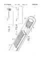
- FIG. 1is a schematic view of a catheter according to a preferred embodiment of the present invention.
- FIG. 2is a magnified view of the distal end region shown in FIG. 1.
- FIG. 3illustrates a distal end region of a catheter according to a preferred embodiment of the present invention.
- FIG. 4illustrates a distal end region of a catheter according to a preferred embodiment of the present invention.
- FIG. 5is a further magnified view of the distal end region shown in FIG. 2.
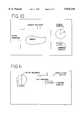
- FIG. 6is a schematic diagram illustrating a catheter inserted into a chamber of the heart of a patient.
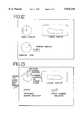
- FIG. 7is a block diagram of an ultrasonic system according to a preferred embodiment of the present invention.
- FIG. 8illustrates a subset of beam data.
- FIG. 9illustrates the subset of beam data unwrapped.
- FIG. 10illustrates a display of the linear phased array according to a preferred embodiment of the present invention.
- FIG. 11illustrates a display of the radial phased array according to a preferred embodiment of the present invention.
- FIG. 12illustrates a display of images from both the linear phased array and the radial phased array according to a preferred embodiment of the present invention.
- FIG. 13illustrates a display of images from both the linear phased array and the radial phased array according to a preferred embodiment of the present invention.
- FIG. 14illustrates the distal end region of another preferred embodiment of a catheter according to the present invention.
- FIG. 15illustrates an ultrasonic system according to a preferred embodiment in which catheter such as that shown in FIG. 14 includes two tracking arrays.
- FIG. 16illustrates the distal region of still another preferred embodiment of a catheter according to the present invention.
- FIG. 1is a schematic view of a catheter 10 according to a preferred embodiment of the present invention.
- the catheter 10includes a body 12, handle 14 and a steering mechanism 16 which couples the proximal end of the body 12 to the handle 14.
- the handle 14 and steering mechanism 16are well known in the art and need not be described in detail.
- the catheterincorporates the steering mechanism described in U.S. patent application Ser. No. 08/792,897, entitled “Steering Mechanism and Steering Line For a Catheter-Mounted Ultrasonic Transducer," filed Jan. 31, 1997 (Attorney Docket No. 5050/171) which is assigned to the assignee of this invention, and which is hereby specifically incorporated by reference.
- the body 12is preferably in the form of a flexible shaft having a longitudinal axis L and a circumference C.
- the body 12has a distal end region 18 which includes at least two ultrasonic transducer arrays that preferably generate different image formats when operated as will be described in greater detail hereinafter.
- the distal end region 18will be described in greater detail with reference to FIGS. 2 and 3.
- the catheterincorporates extended flexible circuits such as described in U.S. patent application Ser. No. 08/791,601, entitled “Ultrasonic Transducer Array With Extended Flexible Circuits,” filed Jan. 31, 1997 (Attorney Docket No. 5050/161) assigned to the assignee of this invention, and which is hereby specifically incorporated herein by reference.
- the catheterincorporates an electrical interconnection system such as that described in U.S. patent application Ser. No. 08/792,291, entitled “Ultrasonic Transducer Assembly With Improved Electrical Interface,” filed Jan. 31, 1997 (Attorney Docket No. 5050/169) assigned to the assignee of this invention, and which is hereby specifically incorporated herein by reference.
- distal end of the cathetermay be formed according to the teachings of U.S. patent application Ser. No. 08/791,598, entitled “Catheter Mounted Phased Array Ultrasound Transducer With Improved Imagery,” filed Jan. 31, 1997 (Attorney Docket No. 5050/170) which is assigned to the assignee of this invention and which is specifically incorporated herein by reference.
- the body 12is preferably constructed of Pebax, manufactured by ELF ATOCHEM North America Inc. of Philadelphia, Pa. and may have a length ranging from about 60 cm to about 120 cm, an inner lumen, and an outer diameter ranging from about 1 mm to about 4 mm.
- FIG. 2is a magnified view of the distal end region 18 of the body 12 of the catheter 10 shown in FIG. 1.
- a first ultrasonic transducer array 20(“first array 20") and a second ultrasonic transducer array 22 (“second array 22") are provided in the distal end region 18 of the catheter 10.
- the first array 20is a linear phased array and the second array 22 is a radial phased array.
- the radial phased arrayis an annular array. When the annular array is excited, all of the emitted acoustic lines have a common origin lying at the center of the annular array. An annular array is used to obtain a 360 degree scan. A 360 degree scan, however, is not always necessary for every application.
- the radial array 22'may be formed by a curved linear phased array which does not form an annulus and only provides less than a 360° scan.
- the radial array 22"may be formed by a substantially planar linear phased array which provides less than a 360° radial scan.
- a radial arrayis any array that generates a scan in a plane perpendicular to the longitudinal axis of the catheter when the array is excited. If the radial array is formed by a linear or curved linear phased array the scan obtained may be linear, sector or VECTORTM format.
- FIG. 5is a further magnified view of the distal end region shown in FIG. 2 with a portion of the body 12 removed to better illustrate the arrays.
- a lens or acoustic window(not shown) may cover the emitting faces of the arrays but has been omitted for purposes of clarity.
- Linear phased ultrasonic array 20is formed by a plurality of transducer elements 30 that are sequentially arranged along the longitudinal axis L of the body 12. The azimuth of the array 20 extends parallel with the longitudinal axis L of the body 12.
- the linear phased array 20is formed by 64 transducer elements having an elevation dimension extending into the Figure of about 2.5 mm.
- the transducer elementsare preferably spaced on a 0.11 mm pitch.
- the linear phased array 20can be of conventional form, such as a flat linear phased array with a cylindrical elevation focusing lens but preferably uses a non-focusing window. All imaging modes including B mode, color Doppler, color Doppler energy and the like are supported.
- the linear phased array 20may include more or less than 64 elements and may have a different pitch and elevation.
- Radial phased ultrasonic transducer array 22 in FIG. 2is formed by a plurality of transducer elements 32 sequentially arranged circumferentially so that it is preferably concentric with the body 12.
- the radial phased array 22is preferably formed by 64 elements having an elevation dimension of 2.5 mm spaced on a 0.11 mm pitch.
- the radial phased array 22is annular to provide a 360° scan.
- An annular arraymay be manufactured from an annulus of piezoelectric material or, alternatively, an annular array may be formed by wrapping a flat transducer array that has been partially diced around a backing block support.
- the radial phased array 22may be formed by fewer elements and thus provide less than a 360° scan.
- each transducer elementincludes two matching layers.
- the matching layer adjacent to the PZTis an epoxy loaded with alumina or lithium aluminum silicate and/or metal power such as tungsten preferably 325 mesh and possesses an acoustic impedance of approximately 8-10 MRayls.
- the second matching layer--further from the PZT--is preferably an unfilled epoxy possessing an impedance of approximately 2.5 MRayls.
- the arrays 20 and 22are constructed using well known techniques which involve laminating the matching layers, an electroded slab of PZT and a flexible circuit onto a thin backing block substrate. Since a very high acoustic loss is desired, it may be preferable to form the backing block from polymeric particles which have been fused to form a macroscopically rigid structure having remnant tortuous permeability, as described in U.S. Pat. No. 5,297,553, assigned to the assignee of this invention. Once the structure has been laminated, individual elements are defined by dicing through the matching layers, PZT and partially into the backing block as is well known. Thereafter, the substrate can be bent to final shape.
- IC multiplexerssuch as those described in Proudian U.S. Pat. No. 4,917,097 and Eberle U.S. Pat. No. 5,368,037 may be incorporated in the distal end of the catheter to couple the signal conductors of the ultrasonic transducer array to the electronics of the ultrasound system.
- IC multiplexerswhich allow a selection between the channels of the radial phased array and the channels of the linear phased array may be used thereby saving space, since when a device smaller than about 2-3 mm in diameter incorporates an ultrasonic array it may become necessary to incorporate multiplexers in the device.
- FIG. 6is a schematic illustrating a catheter inserted into a chamber of the heart of a patient.
- the catheteris inserted into the right atrium of the patient's heart so that the radial phased array 22 can be used to image structures such as the crista terminalis and the coronary sinus orifice as well as give an indication of relative position of the catheter within the chamber.
- the linear phased array 20can be used to image the left atrium and left ventricle as well as other structures such as the mitral, tricuspid, aortic and pulmonary valves as an example.
- the radial phased array 22does not have good image resolution in the far field, it does provide a 360 degree view and outline of the heart chamber which can assist in understanding and interpreting the images obtained by the linear phased array 20. This can be very useful, for example, to an electrophysiologist who is not typically familiar with ultrasound images of the heart.
- the catheteris inserted into the heart by well known techniques which need not be described here in detail.
- the cardiac structures in the very near fieldcan be visualized with the radial phased array 22 and structures deeper or on the opposite side of the heart can be imaged with the linear phased array 20.
- catheters shown in FIGS. 1-5has the linear phased array 20 located proximal of the radial phased array 22, their positions can be reversed so that the radial phased array 22 is proximal of the linear phased array 20.
- the catheters according to the preferred embodiment shown in FIGS. 1-5can be used to reconstruct three dimensional images. More particularly, one array may be used as an imaging array and the other array may be used as a tracking array. For example, if the radial phased array is used as the imaging array and the linear phased array is used as the tracking array, multiple two dimensional image data sets are accumulated from the radial phased array as the catheter is pushed or pulled through the region of interest.
- the linear phased arrayis used for collecting frame to frame tracking data by feature tracking between successive scans using, for example, the sum of absolute differences technique. In this way the longitudinal displacement between successive radial phased scans is obtained and sufficient locating data is acquired to allow the multiple two dimensional image data sets to be assembled into a three dimensional volume.
- both arrays 20 and 22may be used as tracking arrays.
- FIG. 7is a block diagram of an ultrasonic imaging system according to a preferred embodiment of the present invention. The following discussion will first present a system overview, and then a detailed description of select components of the system.
- the system 100includes a beamformer system/signal detector 102 which includes both transmit and receive beamformers and is connected via a multiplexer/demultiplexer 104 to the catheters shown in FIGS. 1-5. If both arrays are operating in a conventional mode where the active transducer aperture is operated simultaneously in a phased manner then any conventional device such as the Acuson XP may be used for element 102. If the arrays are being operated in a synthetic aperture mode, i.e., in which the elements of the array are operated in a sequential rather than simultaneous mode, then it is necessary for the system to store the receive element signals in a temporary store until all of the transmit-receive element combinations have been received.
- the data in the temporary storage registersare delayed and summed to produce a beamformed signal.
- Systems for implementing this type of synthetic focusing by temporarily storing single channel data until all channel data has been receivedare well known, for example, see Proudian U.S. Pat. No. 4,917,097.
- the systempreferably accumulates multiple signals for each transmitter-receiver pair so that signal averaging is achieved thereby resulting in an improvement in the signal to noise ratio.
- a separate receivercan be used for each transmitter channel selected. Such a method is described by O'Donnell et al.
- the catheter arrayis operated with frequencies in the range of about 5 to 20 MHz. If lower frequencies are used, then the linear array has less problems with grating lobes. Alternatively, a lower frequency can be used when operating steered ultrasonic lines as describe in U.S. Pat. No. 5,549,111.
- the linear phased arrayis used to accumulate tracking information, the array can be operated at a high frequency, for example, 20 MHz, since only a relatively small set of data is required in order to derive the motion information.
- the beamformer system/signal detector 102sends excitation signal pulses to the arrays 20 and 22 and supplies summed returning echoes to a signal detector.
- the output of the signal detectoris supplied to a scan converter 124.
- the beamformer system/signal detector 102accumulates data from the array elements in arrays 20 and 22 and forms beamformed acoustic line outputs.
- the scan converter 124controls an output display 126 to display preferably the two images generated by the two arrays 20, 22.
- the output display 126displays the views obtained from the linear phased array 20 and the radial phased array 22 simultaneously on a split screen. Alternatively, the operator may flip back and forth between views. The possible display options will be described in greater detail hereinafter.
- scan-converted image information from the scan converter 124is stored in a data storage system 128.
- the data storage system 28includes two separate storage arrays, each storing data for image frames from a respective one of the arrays 20 and 22.
- the catheters as described in FIGS. 1-5include two separate transducer arrays 20 and 22.
- the linear phased array 20is used for collecting image data that will be used to construct displayed representation of the region of interest.
- the radial phased array 22operates as a tracking array.
- the tracking array 22is used in this preferred embodiment to estimate the motion between respective image data frames from the image data array 20 to allow the image data frames to be registered properly for reconstruction.
- the radial phased array 22operates as the imaging array and the linear phased array 20 operates as the tracking array.
- image information from the image array 20is stored as frames of image data in the storage array 130
- image information from the tracking array 22is stored as respective frames of tracking data in the storage array 132.
- the frames of data in the storage arrays 130 and 132are all time marked, so that they can be associated with one another appropriately. This time marking can take the form of real-time clock information or frame number information, for example.
- the frames of image data in the storage array 130are applied to a computer 136. It is these frames that are used to form the displayed representation of the region of interest.
- the tracking frames stored in storage array 132are not necessarily registered to create a displayed reconstruction of the region of interest but are instead used to determine the relative positions of individual frames of image data from the image data storage array 130.
- the tracking information from the tracking array data storage array 132is supplied to a motion estimator 138.
- the motion estimator 138compares sequences of frame data from the tracking array 22 to estimate a component of motion of the catheter 10 between the respective frames. This estimate of the component of motion is smoothed in logic 140, and then applied to a calculator 142 that calculates a vector value defining the best estimate of the movement between selected frames of the data stored in the image data storage array 130. This vector is then applied as another input to the computer 136.
- the computer 136registers selected frames of image data from the image data storage array 130 with respect to one another by appropriate use of the vectors supplied by the calculator 142. Also any necessary interpolation is done, and the respective frames of image data are stored in proper registration with respect to one another in a three-dimensional data storage device 144.
- the computer 136when operating in a display mode, can select appropriate information from the three-dimensional data storage device 144 to provide a desired image on the display 146. For example, cross sections can be taken in various planes, including a wide variety of planes that do not correspond to the planes of the image data. Also, surface renderings and segmentation displays can be created if desired.
- Common signal conductorscan be used between the beamformer/signal detector 102 and the housing for the catheter 10.
- individual signalsare routed between the signal conductors and the transducer elements of the arrays 20 and 22 by high voltage analog switches or multiplexers.
- the output of the beamformerare polar in format.
- the beamformer outputs linesare detected to form unipolar signals and are scan converted to digital quantities.
- FIG. 8illustrates how a subset of beam data appears in reality , i.e. scan converted into Cartesian coordinates. It is much simpler, however, to unwrap the axial display shown in FIG. 8, i.e. do not scan convert it.
- FIG. 9illustrates how this data is unwrapped to form the straight polar case.
- the increment between successive beam linesis simply their angular separation, for example, 5 degrees.
- FIG. 10illustrates a display of the linear phased array.
- the angle of probe rotation with respect to some user defined arbitrary starting pointhas been measured. This angle is an indication of the relative angular direction of the image frame produced by the linear phased array and may be displayed as a circular icon as shown in FIG. 10 and/or a numeric output as is also displayed.
- the circular iconassumes that the user defined origin is at the top of the circle (for example)and the angular rotation of the probe with respect to this position is shown by an arrow suitably angled with respect to the starting point, i.e., the top of the circle.
- Software for displaying such iconsis well within the scope of those skilled in the art.
- FIG. 11illustrates a display of the radial phased array.
- the radial displayis presented and depth of penetration as detected by motion sensed from the linear array is also displayed.
- the reference point for the start of motion detectionis arbitrary and the user should have the option of resetting it by, for example, selection of a key on a keyboard.
- An icon display for the detected depth relative to the last resetting of the depth measurementis also shown in FIG. 11.
- the iconis in the form of a ruler like object with an arrow pointing to the current position.
- a numeric display indicating millimeters of penetrationis also provided.
- FIG. 12illustrates a display of images from both the linear phased array and the radial phased array.
- both the radial and linear array imagesare displayed each having tick marks indicating a scale in either mm or cm.
- the scan convertersets the millimeter scales to be equal in dimension in both displays. Displaying multiple ultrasound images is relatively well known, for example, simultaneous B-Mode and M-Mode. In this case an angle display is also provided which indicates the present position of the linear array image with respect to the last resetting of the angle measurement.
- FIG. 13illustrates a display of images from both the linear phased array and the radial phased array.
- the radial image displayis rotated according to the detected rotation angle such that the display rotation completely compensates for the physical device rotation.
- the imageappears to remain static though the image is moving with respect to the array.
- the systemdetects that an arbitrary object has moved 20 degrees anticlockwise, the system signals the scan converter to rotate the image 20 degrees clockwise to compensate.
- the concept of the detecting image motion and altering the display to correct for itis described in considerable detail in Bamber U.S. Pat. No. 5,538,004.
- FIG. 14illustrates the distal end region 18' of another preferred embodiment of a catheter according to the present invention.
- a second radial array 200is included on the opposite end of the linear array 20'.
- the second radial arraymay extend 360° or it may extend less than 360°.
- FIG. 15illustrates an ultrasonic system according to a preferred embodiment in which a catheter such as that shown in FIG. 14 includes two tracking arrays.
- FIG. 16illustrates the distal region 18" of still another preferred embodiment of a catheter according to the present invention.
- a curved linear phased array 300is disposed distal of the first radial phased array 302 and is curved.
- a second radial phased array 304shown may be provided proximal of the first radial phased array 302.
- the cathetercan include an absolute sensor for position, orientation, or both, such as a magnetic sensor or an accelerometer.
- the sensor 19may be used to supplement or back up the motion detection approach and may be of the types described in Kelier U.S. Pat. No. 5,353,354 or one of the smaller sensors manufactured by Biosense, Inc. of Setauket, N.Y.
Landscapes
- Health & Medical Sciences (AREA)
- Engineering & Computer Science (AREA)
- Life Sciences & Earth Sciences (AREA)
- Physics & Mathematics (AREA)
- Remote Sensing (AREA)
- Radar, Positioning & Navigation (AREA)
- Acoustics & Sound (AREA)
- Radiology & Medical Imaging (AREA)
- Veterinary Medicine (AREA)
- Heart & Thoracic Surgery (AREA)
- Medical Informatics (AREA)
- Molecular Biology (AREA)
- Surgery (AREA)
- Animal Behavior & Ethology (AREA)
- General Health & Medical Sciences (AREA)
- Public Health (AREA)
- Biomedical Technology (AREA)
- Pathology (AREA)
- Nuclear Medicine, Radiotherapy & Molecular Imaging (AREA)
- Biophysics (AREA)
- Computer Networks & Wireless Communication (AREA)
- General Physics & Mathematics (AREA)
- Gynecology & Obstetrics (AREA)
- Ultra Sonic Daignosis Equipment (AREA)
Abstract
Description
Claims (75)
Priority Applications (3)
| Application Number | Priority Date | Filing Date | Title |
|---|---|---|---|
| US08/807,621US5876345A (en) | 1997-02-27 | 1997-02-27 | Ultrasonic catheter, system and method for two dimensional imaging or three-dimensional reconstruction |
| AU63412/98AAU6341298A (en) | 1997-02-27 | 1998-02-27 | Ultrasonic catheter, system and method for two-dimensional imaging or three-dimensional reconstruction |
| PCT/US1998/003841WO1998037812A1 (en) | 1997-02-27 | 1998-02-27 | Ultrasonic catheter, system and method for two-dimensional imaging or three-dimensional reconstruction |
Applications Claiming Priority (1)
| Application Number | Priority Date | Filing Date | Title |
|---|---|---|---|
| US08/807,621US5876345A (en) | 1997-02-27 | 1997-02-27 | Ultrasonic catheter, system and method for two dimensional imaging or three-dimensional reconstruction |
Publications (1)
| Publication Number | Publication Date |
|---|---|
| US5876345Atrue US5876345A (en) | 1999-03-02 |
Family
ID=25196810
Family Applications (1)
| Application Number | Title | Priority Date | Filing Date |
|---|---|---|---|
| US08/807,621Expired - LifetimeUS5876345A (en) | 1997-02-27 | 1997-02-27 | Ultrasonic catheter, system and method for two dimensional imaging or three-dimensional reconstruction |
Country Status (3)
| Country | Link |
|---|---|
| US (1) | US5876345A (en) |
| AU (1) | AU6341298A (en) |
| WO (1) | WO1998037812A1 (en) |
Cited By (159)
| Publication number | Priority date | Publication date | Assignee | Title |
|---|---|---|---|---|
| US6045508A (en)* | 1997-02-27 | 2000-04-04 | Acuson Corporation | Ultrasonic probe, system and method for two-dimensional imaging or three-dimensional reconstruction |
| US6102865A (en)* | 1996-02-29 | 2000-08-15 | Acuson Corporation | Multiple ultrasound image registration system, method and transducer |
| US6123673A (en)* | 1993-02-01 | 2000-09-26 | Endosonics Corporation | Method of making an ultrasound transducer assembly |
| US6148095A (en)* | 1997-09-08 | 2000-11-14 | University Of Iowa Research Foundation | Apparatus and method for determining three-dimensional representations of tortuous vessels |
| US6152878A (en)* | 1997-06-19 | 2000-11-28 | Medinol Ltd. | Intravascular ultrasound enhanced image and signal processing |
| US6162175A (en)* | 1997-09-29 | 2000-12-19 | Acuson Corporation | Multi-array pencil-sized untrasound transducer and method of imaging and manufacture |
| US6171247B1 (en)* | 1997-06-13 | 2001-01-09 | Mayo Foundation For Medical Education And Research | Underfluid catheter system and method having a rotatable multiplane transducer |
| US6228032B1 (en)* | 1997-01-31 | 2001-05-08 | Acuson Corporation | Steering mechanism and steering line for a catheter-mounted ultrasonic transducer |
| US6241675B1 (en)* | 1998-06-09 | 2001-06-05 | Volumetrics Medical Imaging | Methods and systems for determining velocity of tissue using three dimensional ultrasound data |
| US6248075B1 (en)* | 1997-09-26 | 2001-06-19 | Ep Technologies, Inc. | Method and apparatus for fixing the anatomical orientation of a displayed ultrasound generated image |
| US6261234B1 (en)* | 1998-05-07 | 2001-07-17 | Diasonics Ultrasound, Inc. | Method and apparatus for ultrasound imaging with biplane instrument guidance |
| US6275724B1 (en)* | 1998-03-27 | 2001-08-14 | Intravascular Research Limited | Medical ultrasonic imaging |
| WO2001058601A1 (en)* | 2000-02-09 | 2001-08-16 | Endosonics Corporation | Forward and side looking ultrasonic imaging |
| US6306096B1 (en) | 1991-11-08 | 2001-10-23 | Mayo Foundation For Medical Education And Research | Volumetric image ultrasound transducer underfluid catheter system |
| USD455210S1 (en) | 1997-01-31 | 2002-04-02 | Acuson Corporation | Ultrasonic transducer assembly controller |
| US20020042565A1 (en)* | 1999-08-05 | 2002-04-11 | Cooper Joel D. | Conduits for maintaining openings in tissue |
| US6398736B1 (en) | 1999-03-31 | 2002-06-04 | Mayo Foundation For Medical Education And Research | Parametric imaging ultrasound catheter |
| US6398731B1 (en)* | 1997-07-25 | 2002-06-04 | Tomtec Imaging Systems Gmbh | Method for recording ultrasound images of moving objects |
| US6423002B1 (en) | 1999-06-24 | 2002-07-23 | Acuson Corporation | Intra-operative diagnostic ultrasound multiple-array transducer probe and optional surgical tool |
| US20020111620A1 (en)* | 2001-02-14 | 2002-08-15 | Broncus Technologies, Inc. | Devices and methods for maintaining collateral channels in tissue |
| US20020138074A1 (en)* | 1999-08-05 | 2002-09-26 | Thomas Keast | Devices for applying energy to tissue |
| US6464645B1 (en) | 1997-01-31 | 2002-10-15 | Acuson Corporation | Ultrasonic transducer assembly controller |
| US6468221B2 (en)* | 2000-11-21 | 2002-10-22 | Asahi Kogaku Kogyo Kabushiki Kaisha | Ultrasonic endoscope |
| USD465024S1 (en) | 1998-01-31 | 2002-10-29 | Acuson Corporation | Ultrasonic transducer assembly controller |
| US6482161B1 (en) | 2000-06-29 | 2002-11-19 | Acuson Corporation | Medical diagnostic ultrasound system and method for vessel structure analysis |
| US6488631B2 (en)* | 2000-11-21 | 2002-12-03 | Asahi Kogaku Kogyo Kabushiki Kaisha | Ultrasonic endoscope |
| US6488632B2 (en)* | 2000-11-21 | 2002-12-03 | Asahi Kogaku Kogyo Kabushiki Kaisha | Ultrasonic endoscope |
| US6503202B1 (en) | 2000-06-29 | 2003-01-07 | Acuson Corp. | Medical diagnostic ultrasound system and method for flow analysis |
| US6511427B1 (en) | 2000-03-10 | 2003-01-28 | Acuson Corporation | System and method for assessing body-tissue properties using a medical ultrasound transducer probe with a body-tissue parameter measurement mechanism |
| US6517488B1 (en) | 2000-06-29 | 2003-02-11 | Acuson Corporation | Medical diagnostic ultrasound system and method for identifying constrictions |
| WO2003011139A1 (en)* | 2001-07-31 | 2003-02-13 | Koninklijke Philips Electronics N.V. | Transesophageal and transnasal, transesophageal ultrasound imaging systems |
| US6527717B1 (en) | 2000-03-10 | 2003-03-04 | Acuson Corporation | Tissue motion analysis medical diagnostic ultrasound system and method |
| US20030125719A1 (en)* | 2001-12-31 | 2003-07-03 | Furnish Simon M. | Multi-fiber catheter probe arrangement for tissue analysis or treatment |
| US20030125630A1 (en)* | 2001-12-31 | 2003-07-03 | Furnish Simon M. | Catheter probe arrangement for tissue analysis by radiant energy delivery and radiant energy collection |
| US6605043B1 (en) | 1998-11-19 | 2003-08-12 | Acuson Corp. | Diagnostic medical ultrasound systems and transducers utilizing micro-mechanical components |
| US6607488B1 (en) | 2000-03-02 | 2003-08-19 | Acuson Corporation | Medical diagnostic ultrasound system and method for scanning plane orientation |
| US6612992B1 (en) | 2000-03-02 | 2003-09-02 | Acuson Corp | Medical diagnostic ultrasound catheter and method for position determination |
| US20030199756A1 (en)* | 2002-04-17 | 2003-10-23 | Olympus Optical Co., Ltd. | Ultrasonic diagnostic apparatus and ultrasonic diagnostic method |
| US6645145B1 (en)* | 1998-11-19 | 2003-11-11 | Siemens Medical Solutions Usa, Inc. | Diagnostic medical ultrasound systems and transducers utilizing micro-mechanical components |
| US20030216681A1 (en)* | 1998-06-29 | 2003-11-20 | John Zhang | Sheath for use with an ultrasound element |
| US6697667B1 (en) | 2001-05-31 | 2004-02-24 | Advanced Cardiovascular Systems, Inc. | Apparatus and method for locating coronary sinus |
| WO2004021040A1 (en)* | 2002-08-29 | 2004-03-11 | Koninklijke Philips Electronics N.V. | Biplane ultrasonic imaging with icon depicting the mutual plane orientation |
| US6712812B2 (en) | 1999-08-05 | 2004-03-30 | Broncus Technologies, Inc. | Devices for creating collateral channels |
| US6716178B1 (en) | 2001-05-31 | 2004-04-06 | Advanced Cardiovascular Systems, Inc. | Apparatus and method for performing thermal and laser doppler velocimetry measurements |
| US6716166B2 (en) | 2000-08-18 | 2004-04-06 | Biosense, Inc. | Three-dimensional reconstruction using ultrasound |
| US20040073155A1 (en)* | 2000-01-14 | 2004-04-15 | Broncus Technologies, Inc. | Methods and devices for maintaining patency of surgically created channels in tissue |
| WO2003053491A3 (en)* | 2001-11-09 | 2004-04-22 | Cardio Optics Inc | Coronary sinus access catheter with forward-imaging |
| US6730033B2 (en) | 2002-05-16 | 2004-05-04 | Siemens Medical Systems, Inc. | Two dimensional array and methods for imaging in three dimensions |
| US6746401B2 (en)* | 2002-05-06 | 2004-06-08 | Scimed Life Systems, Inc. | Tissue ablation visualization |
| US6749606B2 (en) | 1999-08-05 | 2004-06-15 | Thomas Keast | Devices for creating collateral channels |
| US20040114146A1 (en)* | 2002-12-13 | 2004-06-17 | Scimed Life Systems, Inc. | Method and apparatus for orienting a medical image |
| US20040152986A1 (en)* | 2003-01-23 | 2004-08-05 | Fidel Howard F. | Ultrasonic imaging device, system and method of use |
| US6773402B2 (en) | 2001-07-10 | 2004-08-10 | Biosense, Inc. | Location sensing with real-time ultrasound imaging |
| US20040199228A1 (en)* | 2003-01-03 | 2004-10-07 | Wilson Richard R. | Ultrasonic catheter with axial energy field |
| US20040249287A1 (en)* | 2001-12-18 | 2004-12-09 | Olympus Optical Co., Ltd. | Ultrasonic diagnosis apparatus |
| US20040254469A1 (en)* | 2003-05-29 | 2004-12-16 | Transonic Systems, Inc. | Acoustically coupled ultrasonic transit time flow sensors |
| US20040267086A1 (en)* | 2003-06-26 | 2004-12-30 | Anstadt Mark P. | Sensor-equipped and algorithm-controlled direct mechanical ventricular assist device |
| US20050010112A1 (en)* | 1997-05-01 | 2005-01-13 | Bennett Frederick J. | Ultrasound assembly with increased efficacy |
| US20050060044A1 (en)* | 1999-08-05 | 2005-03-17 | Ed Roschak | Methods and devices for maintaining patency of surgically created channels in a body organ |
| US20050056292A1 (en)* | 1999-08-05 | 2005-03-17 | Cooper Joel D. | Devices for maintaining patency of surgically created channels in tissue |
| US20050060042A1 (en)* | 2001-09-04 | 2005-03-17 | Broncus Technologies, Inc. | Methods and devices for maintaining surgically created channels in a body organ |
| US20050075572A1 (en)* | 2003-10-01 | 2005-04-07 | Mills David M. | Focusing micromachined ultrasonic transducer arrays and related methods of manufacture |
| US20050107783A1 (en)* | 1999-08-05 | 2005-05-19 | Broncus Technologies, Inc. | Devices for applying energy to tissue |
| US20050137518A1 (en)* | 2002-04-19 | 2005-06-23 | Broncus Technologies, Inc. | Devices for maintaining surgically created openings |
| US20050137611A1 (en)* | 2001-09-04 | 2005-06-23 | Broncus Technologies, Inc. | Methods and devices for maintaining surgically created channels in a body organ |
| US20050137715A1 (en)* | 1999-08-05 | 2005-06-23 | Broncus Technologies, Inc. | Methods and devices for maintaining patency of surgically created channels in a body organ |
| US20050209578A1 (en)* | 2004-01-29 | 2005-09-22 | Christian Evans Edward A | Ultrasonic catheter with segmented fluid delivery |
| US20050215895A1 (en)* | 2003-11-12 | 2005-09-29 | Popp Richard L | Devices and methods for obtaining three-dimensional images of an internal body site |
| US20060074309A1 (en)* | 2002-11-06 | 2006-04-06 | Odile Bonnefous | Phased array acoustic system for 3d imaging of moving parts |
| US20060074319A1 (en)* | 2004-09-27 | 2006-04-06 | Siemens Medical Solutions Usa, Inc. | Image plane sensing methods and systems for intra-patient probes |
| US20060084875A1 (en)* | 2004-10-14 | 2006-04-20 | Scimed Life Systems, Inc. | Integrated bias circuitry for ultrasound imaging devices |
| US20060116749A1 (en)* | 2003-07-18 | 2006-06-01 | Broncus Technologies, Inc. | Devices for maintaining patency of surgically created channels in tissue |
| WO2006076428A1 (en)* | 2005-01-11 | 2006-07-20 | Boston Scientific Limited, A Corporation Of Republic Of Ireland | Systems and methods for three dimensional imaging with an orientation adjustable array |
| US20060173310A1 (en)* | 2003-07-03 | 2006-08-03 | Satoshi Tamano | Ultrasonic probe and ultrasonic diagnostic device |
| US20060241445A1 (en)* | 2005-04-26 | 2006-10-26 | Altmann Andres C | Three-dimensional cardial imaging using ultrasound contour reconstruction |
| US20060241483A1 (en)* | 2000-07-20 | 2006-10-26 | Volcano Corp. | Ultrasonic imaging catheters |
| US20060253029A1 (en)* | 2005-04-26 | 2006-11-09 | Altmann Andres C | Display of two-dimensional ultrasound fan |
| US20060253024A1 (en)* | 2005-04-26 | 2006-11-09 | Altmann Andres C | Software product for three-dimensional cardiac imaging using ultrasound contour reconstruction |
| US20060253032A1 (en)* | 2005-04-26 | 2006-11-09 | Altmann Andres C | Display of catheter tip with beam direction for ultrasound system |
| US20060253031A1 (en)* | 2005-04-26 | 2006-11-09 | Altmann Andres C | Registration of ultrasound data with pre-acquired image |
| US20060280772A1 (en)* | 2001-09-04 | 2006-12-14 | Broncus Technologies, Inc. | Methods and devices for maintaining surgically created channels in a body organ |
| US20060280773A1 (en)* | 1999-08-05 | 2006-12-14 | Broncus Technologies, Inc. | Methods and devices for maintaining patency of surgically created channels in a body organ |
| US20070038081A1 (en)* | 2003-09-04 | 2007-02-15 | Koninklijke Philips Electronics N.V. | Device and method for displaying ultrasound images of a vessel |
| US7186246B2 (en) | 1997-05-01 | 2007-03-06 | Ekos Corporation | Ultrasound catheter with utility lumen |
| US20070083099A1 (en)* | 2005-09-29 | 2007-04-12 | Henderson Stephen W | Path related three dimensional medical imaging |
| US20070118035A1 (en)* | 2005-11-22 | 2007-05-24 | General Electric Company | Catheter tip |
| EP1669030A3 (en)* | 2003-06-11 | 2007-06-20 | Olympus Corporation | Ultrasonic diagnosis apparatus |
| US20070161951A1 (en)* | 2004-01-29 | 2007-07-12 | Ekos Corporation | Treatment of vascular occlusions using elevated temperatures |
| US20070232916A1 (en)* | 2004-10-08 | 2007-10-04 | Koji Waki | Ultrasound Diagnostic Apparatus |
| US20080009745A1 (en)* | 2006-04-04 | 2008-01-10 | Volcano Corporation | Ultrasound catheter and hand-held device for manipulating a transducer on the catheter's distal end |
| US7329223B1 (en) | 2001-05-31 | 2008-02-12 | Abbott Cardiovascular Systems Inc. | Catheter with optical fiber sensor |
| US20080103417A1 (en)* | 2006-10-27 | 2008-05-01 | Azita Soltani | Catheter with multiple ultrasound radiating members |
| US20080125659A1 (en)* | 2006-11-28 | 2008-05-29 | Siemens Medical Solutions Usa, Inc. | Helical acoustic array for medical ultrasound |
| US20080123911A1 (en)* | 2006-09-26 | 2008-05-29 | Duc Lam | Systems and Methods for Restoring a Medical Image Affected by Nonuniform Rotational Distortion |
| US20080146941A1 (en)* | 2006-12-13 | 2008-06-19 | Ep Medsystems, Inc. | Catheter Position Tracking for Intracardiac Catheters |
| US20080146934A1 (en)* | 2006-12-08 | 2008-06-19 | Gerald Czygan | Implantable medical system with acoustic sensor to measure mitral blood flow |
| US7422563B2 (en) | 1999-08-05 | 2008-09-09 | Broncus Technologies, Inc. | Multifunctional tip catheter for applying energy to tissue and detecting the presence of blood flow |
| US20080221448A1 (en)* | 2007-03-07 | 2008-09-11 | Khuri-Yakub Butrus T | Image-guided delivery of therapeutic tools duing minimally invasive surgeries and interventions |
| US20080294052A1 (en)* | 2007-05-21 | 2008-11-27 | Siemens Medical Solutions Usa, Inc. | Biplane ultrasound imaging and corresponding transducer |
| US20080300487A1 (en)* | 2007-06-04 | 2008-12-04 | Assaf Govari | Cardiac mechanical assessment using ultrasound |
| US7462162B2 (en) | 2001-09-04 | 2008-12-09 | Broncus Technologies, Inc. | Antiproliferative devices for maintaining patency of surgically created channels in a body organ |
| US20080319376A1 (en)* | 2007-06-22 | 2008-12-25 | Ekos Corporation | Method and apparatus for treatment of intracranial hemorrhages |
| US20090010459A1 (en)* | 2006-11-28 | 2009-01-08 | Garbini Lex J | Multi-twisted acoustic array for medical ultrasound |
| US20090076483A1 (en)* | 2007-09-14 | 2009-03-19 | Kenneth Danehorn | Catheter localization system |
| US20090082674A1 (en)* | 2007-09-21 | 2009-03-26 | Olympus Medical Systems Corp. | Ultrasound diagnostic apparatus |
| US7532920B1 (en) | 2001-05-31 | 2009-05-12 | Advanced Cardiovascular Systems, Inc. | Guidewire with optical fiber |
| US20090245261A1 (en)* | 2008-03-31 | 2009-10-01 | Faisal Andre Khan | Hierarchical virtual private lan service hub connectivity failure recovery |
| US20090247879A1 (en)* | 2004-03-09 | 2009-10-01 | Angelsen Bjorn A J | Extended ultrasound imaging probe for insertion into the body |
| US20090248041A1 (en)* | 2008-03-31 | 2009-10-01 | Intuitive Surgical, Inc. | Robotic surgical tools for laser marking and laser cutting |
| US20090292209A1 (en)* | 2007-07-27 | 2009-11-26 | Andreas Hadjicostis | Intracardiac catheters with image field electrodes |
| US20090326372A1 (en)* | 2008-06-30 | 2009-12-31 | Darlington Gregory | Compound Imaging with HIFU Transducer and Use of Pseudo 3D Imaging |
| US7708712B2 (en) | 2001-09-04 | 2010-05-04 | Broncus Technologies, Inc. | Methods and devices for maintaining patency of surgically created channels in a body organ |
| US7727178B2 (en) | 2001-12-03 | 2010-06-01 | Ekos Corporation | Catheter with multiple ultrasound radiating members |
| US20100152523A1 (en)* | 2005-11-28 | 2010-06-17 | Myocardiocare, Inc. | Method and Apparatus for Minimally Invasive Direct Mechanical Ventricular Actuation |
| US20100179433A1 (en)* | 2003-11-26 | 2010-07-15 | Roth Scott L | Transesophageal ultrasound using a narrow probe |
| US20100210945A1 (en)* | 2009-02-17 | 2010-08-19 | Siemens Medical Solutions Usa, Inc. | System for Cardiac Ultrasound Image Acquisition |
| US20100222679A1 (en)* | 2009-02-27 | 2010-09-02 | Timothy Jon Hall | Method and apparatus for assessing risk of preterm delivery |
| US20100286527A1 (en)* | 2009-05-08 | 2010-11-11 | Penrith Corporation | Ultrasound system with multi-head wireless probe |
| AU2006201646B2 (en)* | 2005-04-26 | 2011-01-06 | Biosense Webster, Inc. | Display of catheter tip with beam direction for ultrasound system |
| US20110196189A1 (en)* | 2010-02-09 | 2011-08-11 | Myocardiocare, Inc. | Extra-cardiac differential ventricular actuation by inertial and baric partitioning |
| US20110201974A1 (en)* | 2010-02-17 | 2011-08-18 | Ekos Corporation | Treatment of vascular occlusions using ultrasonic energy and microbubbles |
| CN102415906A (en)* | 2011-09-06 | 2012-04-18 | 深圳市开立科技有限公司 | Tri-plane ultrasonic probe |
| US8226629B1 (en) | 2002-04-01 | 2012-07-24 | Ekos Corporation | Ultrasonic catheter power control |
| US8308682B2 (en) | 2003-07-18 | 2012-11-13 | Broncus Medical Inc. | Devices for maintaining patency of surgically created channels in tissue |
| US8311613B2 (en) | 2007-06-20 | 2012-11-13 | Siemens Aktiengesellschaft | Electrode catheter positioning system |
| US8409167B2 (en) | 2004-07-19 | 2013-04-02 | Broncus Medical Inc | Devices for delivering substances through an extra-anatomic opening created in an airway |
| US8709034B2 (en) | 2011-05-13 | 2014-04-29 | Broncus Medical Inc. | Methods and devices for diagnosing, monitoring, or treating medical conditions through an opening through an airway wall |
| US20140187960A1 (en)* | 2012-12-28 | 2014-07-03 | Volcano Corporation | Intravascular Ultrasound Imaging Apparatus, Interface, Architecture, and Method of Manufacturing |
| US20140243622A1 (en)* | 2006-04-11 | 2014-08-28 | The University Of Nottingham | Photoplethysmography |
| US20150025518A1 (en)* | 2012-04-05 | 2015-01-22 | Terumo Kabushiki Kaisha | Blood vessel insertion-type treatment device |
| US9107590B2 (en) | 2004-01-29 | 2015-08-18 | Ekos Corporation | Method and apparatus for detecting vascular conditions with a catheter |
| US20150305716A1 (en)* | 2014-04-28 | 2015-10-29 | Koninklijke Philips N.V | Ultrasound Transducer Array Apparatus and Method of Imaging Using Transducer Arrays |
| US9345532B2 (en) | 2011-05-13 | 2016-05-24 | Broncus Medical Inc. | Methods and devices for ablation of tissue |
| US20160207068A1 (en)* | 2013-08-26 | 2016-07-21 | Koninklijke Philips N.V. | Ultrasound transducer assembly and method for manufacturing an ultrasound transducer assembly |
| US20160338675A1 (en)* | 2015-05-18 | 2016-11-24 | Toshiba Medical Systems Corporation | Ultrasonic probe and ultrasonic diagnostic apparatus |
| US9579494B2 (en) | 2013-03-14 | 2017-02-28 | Ekos Corporation | Method and apparatus for drug delivery to a target site |
| US20170252010A1 (en)* | 2016-03-04 | 2017-09-07 | Toshiba Medical Systems Corporation | Ultrasonic diagnostic apparatus and method for generating ultrasonic image |
| US9849273B2 (en) | 2009-07-03 | 2017-12-26 | Ekos Corporation | Power parameters for ultrasonic catheter |
| US10092742B2 (en) | 2014-09-22 | 2018-10-09 | Ekos Corporation | Catheter system |
| EP3229700A4 (en)* | 2014-09-11 | 2018-10-17 | Ryan, Stephen, E. | Distance, diameter and area measuring device |
| US10182833B2 (en) | 2007-01-08 | 2019-01-22 | Ekos Corporation | Power parameters for ultrasonic catheter |
| US10188410B2 (en) | 2007-01-08 | 2019-01-29 | Ekos Corporation | Power parameters for ultrasonic catheter |
| US10232196B2 (en) | 2006-04-24 | 2019-03-19 | Ekos Corporation | Ultrasound therapy system |
| US10272260B2 (en) | 2011-11-23 | 2019-04-30 | Broncus Medical Inc. | Methods and devices for diagnosing, monitoring, or treating medical conditions through an opening through an airway wall |
| EP3482691A1 (en)* | 2017-11-14 | 2019-05-15 | Koninklijke Philips N.V. | Ice catheter with multiple transducer arrays |
| US10383542B2 (en) | 2013-03-14 | 2019-08-20 | St. Jude Medical, Atrial Fibrillation Division, Inc. | Device, system, and method for intracardiac diagnosis or therapy with localization |
| US20200129154A1 (en)* | 2017-03-20 | 2020-04-30 | Exact Imaging Inc. | Method and system for visually assisting an operator of an ultrasound system |
| US10656025B2 (en) | 2015-06-10 | 2020-05-19 | Ekos Corporation | Ultrasound catheter |
| US10888657B2 (en) | 2010-08-27 | 2021-01-12 | Ekos Corporation | Method and apparatus for treatment of intracranial hemorrhages |
| US11304677B2 (en)* | 2016-09-30 | 2022-04-19 | Shenzhen Mindray Bio-Medical Electronics Co., Ltd. | Ultrasonic blood flow parameter displaying method, and ultrasonic imaging system therefor |
| US11383076B2 (en) | 2020-10-01 | 2022-07-12 | Lifebridge Technologies, Llc | Pump regulation based on heart size and function |
| US11458290B2 (en) | 2011-05-11 | 2022-10-04 | Ekos Corporation | Ultrasound system |
| US11660070B2 (en)* | 2016-03-30 | 2023-05-30 | Philips Image Guided Therapy Corporation | Phased array intravascular devices, systems, and methods utilizing photoacoustic and ultrasound techniques |
| US11832877B2 (en) | 2017-04-03 | 2023-12-05 | Broncus Medical Inc. | Electrosurgical access sheath |
| US11896812B1 (en) | 2023-01-27 | 2024-02-13 | Lifebridge Technologies Llc | Versatile modular heart pump for non-blood contacting ventricular function augmentation |
| US12064288B2 (en) | 2013-03-15 | 2024-08-20 | Provisio Medical, Inc. | Distance, diameter and area determining device |
| US12115363B1 (en) | 2023-08-10 | 2024-10-15 | Lifebridge Technologies Llc | System and method for introducing a construct either on or around the surface of the heart |
| US12263332B2 (en) | 2022-09-13 | 2025-04-01 | Lifebridge Technologies Llc | Material characteristics ideal for providing either partial or total mechanical support to the failing or arrested heart and method for developing ideal characteristics for underlying cardiac disorders |
| US12440338B2 (en) | 2023-12-05 | 2025-10-14 | Lifebridge Technologies Llc | Minimally invasive heart pump with modular adjustable construct insertion |
Families Citing this family (3)
| Publication number | Priority date | Publication date | Assignee | Title |
|---|---|---|---|---|
| EP1058594A2 (en)* | 1998-12-10 | 2000-12-13 | William Forrest Fagan | Method for the manufacture of hearing aid shells |
| JP2009066074A (en)* | 2007-09-11 | 2009-04-02 | Olympus Medical Systems Corp | Ultrasonic diagnostic equipment |
| CN102047140B (en) | 2008-06-05 | 2015-06-03 | 皇家飞利浦电子股份有限公司 | Extended field of view ultrasonic imaging with guided EFOV scanning |
Citations (52)
| Publication number | Priority date | Publication date | Assignee | Title |
|---|---|---|---|---|
| US4140022A (en)* | 1977-12-20 | 1979-02-20 | Hewlett-Packard Company | Acoustic imaging apparatus |
| USRE30397E (en)* | 1976-04-27 | 1980-09-09 | Three-dimensional ultrasonic imaging of animal soft tissue | |
| US4241608A (en)* | 1978-01-24 | 1980-12-30 | Unirad Corporation | Ultrasonic scanner |
| US4635293A (en)* | 1984-02-24 | 1987-01-06 | Kabushiki Kaisha Toshiba | Image processing system |
| US4841977A (en)* | 1987-05-26 | 1989-06-27 | Inter Therapy, Inc. | Ultra-thin acoustic transducer and balloon catheter using same in imaging array subassembly |
| US4917097A (en)* | 1987-10-27 | 1990-04-17 | Endosonics Corporation | Apparatus and method for imaging small cavities |
| US4937775A (en)* | 1988-11-21 | 1990-06-26 | General Electric Company | Apparatus for the cross-correlation of a pair of complex sampled signals |
| US4947852A (en)* | 1988-10-05 | 1990-08-14 | Cardiometrics, Inc. | Apparatus and method for continuously measuring volumetric blood flow using multiple transducer and catheter for use therewith |
| US5000185A (en)* | 1986-02-28 | 1991-03-19 | Cardiovascular Imaging Systems, Inc. | Method for intravascular two-dimensional ultrasonography and recanalization |
| US5014710A (en)* | 1988-09-13 | 1991-05-14 | Acuson Corporation | Steered linear color doppler imaging |
| US5070879A (en)* | 1989-11-30 | 1991-12-10 | Acoustic Imaging Technologies Corp. | Ultrasound imaging method and apparatus |
| US5081993A (en)* | 1987-11-11 | 1992-01-21 | Circulation Research Limited | Methods and apparatus for the examination and treatment of internal organs |
| US5103129A (en)* | 1990-07-26 | 1992-04-07 | Acoustic Imaging Technologies Corporation | Fixed origin biplane ultrasonic transducer |
| US5107844A (en)* | 1989-04-06 | 1992-04-28 | Olympus Optical Co., Ltd. | Ultrasonic observing apparatus |
| US5127409A (en)* | 1991-04-25 | 1992-07-07 | Daigle Ronald E | Ultrasound Doppler position sensing |
| US5159931A (en)* | 1988-11-25 | 1992-11-03 | Riccardo Pini | Apparatus for obtaining a three-dimensional reconstruction of anatomic structures through the acquisition of echographic images |
| US5161537A (en)* | 1990-03-26 | 1992-11-10 | Matsushita Electric Industrial Co., Ltd. | Ultrasonic diagnostic system |
| US5186176A (en)* | 1990-04-11 | 1993-02-16 | Kabushiki Kaisha Toshiba | Ultrasonic diagnosis apparatus |
| US5186177A (en)* | 1991-12-05 | 1993-02-16 | General Electric Company | Method and apparatus for applying synthetic aperture focusing techniques to a catheter based system for high frequency ultrasound imaging of small vessels |
| US5199437A (en)* | 1991-09-09 | 1993-04-06 | Sensor Electronics, Inc. | Ultrasonic imager |
| US5211176A (en)* | 1990-11-30 | 1993-05-18 | Fuji Photo Optical Co., Ltd. | Ultrasound examination system |
| US5257629A (en)* | 1989-05-26 | 1993-11-02 | Intravascular Research Limited | Methods and apparatus for the examination and treatment of internal organs |
| US5273045A (en)* | 1991-05-23 | 1993-12-28 | Fujitsu Limited | Ultrasonic equipment and its catheter-type ultrasonic probe |
| US5315512A (en)* | 1989-09-01 | 1994-05-24 | Montefiore Medical Center | Apparatus and method for generating image representations of a body utilizing an ultrasonic imaging subsystem and a three-dimensional digitizer subsystem |
| US5325860A (en)* | 1991-11-08 | 1994-07-05 | Mayo Foundation For Medical Education And Research | Ultrasonic and interventional catheter and method |
| US5327895A (en)* | 1991-07-10 | 1994-07-12 | Kabushiki Kaisha Toshiba | Ultrasonic probe and ultrasonic diagnosing system using ultrasonic probe |
| US5353354A (en)* | 1990-11-22 | 1994-10-04 | Advanced Technology Laboratories, Inc. | Acquisition and display of ultrasonic images from sequentially oriented image planes |
| US5368037A (en)* | 1993-02-01 | 1994-11-29 | Endosonics Corporation | Ultrasound catheter |
| US5377682A (en)* | 1991-09-05 | 1995-01-03 | Matsushita Electric Industrial Co., Ltd. | Ultrasonic probe for transmission and reception of ultrasonic wave and ultrasonic diagnostic apparatus including ultrasonic probe |
| US5398691A (en)* | 1993-09-03 | 1995-03-21 | University Of Washington | Method and apparatus for three-dimensional translumenal ultrasonic imaging |
| US5456259A (en)* | 1991-07-30 | 1995-10-10 | Intravascular Research Limited | Ultrasonic transducer arrangement and catheter |
| US5469851A (en)* | 1994-08-09 | 1995-11-28 | Hewlett-Packard Company | Time multiplexed digital ultrasound beamformer |
| US5471988A (en)* | 1993-12-24 | 1995-12-05 | Olympus Optical Co., Ltd. | Ultrasonic diagnosis and therapy system in which focusing point of therapeutic ultrasonic wave is locked at predetermined position within observation ultrasonic scanning range |
| US5487388A (en)* | 1994-11-01 | 1996-01-30 | Interspec. Inc. | Three dimensional ultrasonic scanning devices and techniques |
| US5492125A (en)* | 1995-02-10 | 1996-02-20 | University Of Washington | Ultrasound signal processing apparatus |
| US5497776A (en)* | 1993-08-05 | 1996-03-12 | Olympus Optical Co., Ltd. | Ultrasonic image diagnosing apparatus for displaying three-dimensional image |
| US5503153A (en)* | 1995-06-30 | 1996-04-02 | Siemens Medical Systems, Inc. | Noise suppression method utilizing motion compensation for ultrasound images |
| US5517537A (en)* | 1994-08-18 | 1996-05-14 | General Electric Company | Integrated acoustic leak detection beamforming system |
| US5538004A (en)* | 1995-02-28 | 1996-07-23 | Hewlett-Packard Company | Method and apparatus for tissue-centered scan conversion in an ultrasound imaging system |
| US5558091A (en)* | 1993-10-06 | 1996-09-24 | Biosense, Inc. | Magnetic determination of position and orientation |
| US5566674A (en)* | 1995-06-30 | 1996-10-22 | Siemens Medical Systems, Inc. | Method and apparatus for reducing ultrasound image shadowing and speckle |
| US5570691A (en)* | 1994-08-05 | 1996-11-05 | Acuson Corporation | Method and apparatus for real-time, concurrent adaptive focusing in an ultrasound beamformer imaging system |
| US5575286A (en)* | 1995-03-31 | 1996-11-19 | Siemens Medical Systems, Inc. | Method and apparatus for generating large compound ultrasound image |
| US5582173A (en)* | 1995-09-18 | 1996-12-10 | Siemens Medical Systems, Inc. | System and method for 3-D medical imaging using 2-D scan data |
| US5590654A (en)* | 1993-06-07 | 1997-01-07 | Prince; Martin R. | Method and apparatus for magnetic resonance imaging of arteries using a magnetic resonance contrast agent |
| US5606975A (en)* | 1994-09-19 | 1997-03-04 | The Board Of Trustees Of The Leland Stanford Junior University | Forward viewing ultrasonic imaging catheter |
| US5608849A (en)* | 1991-08-27 | 1997-03-04 | King, Jr.; Donald | Method of visual guidance for positioning images or data in three-dimensional space |
| US5699805A (en)* | 1996-06-20 | 1997-12-23 | Mayo Foundation For Medical Education And Research | Longitudinal multiplane ultrasound transducer underfluid catheter system |
| US5704361A (en)* | 1991-11-08 | 1998-01-06 | Mayo Foundation For Medical Education And Research | Volumetric image ultrasound transducer underfluid catheter system |
| US5713363A (en)* | 1991-11-08 | 1998-02-03 | Mayo Foundation For Medical Education And Research | Ultrasound catheter and method for imaging and hemodynamic monitoring |
| US5724978A (en)* | 1996-09-20 | 1998-03-10 | Cardiovascular Imaging Systems, Inc. | Enhanced accuracy of three-dimensional intraluminal ultrasound (ILUS) image reconstruction |
| US5776067A (en)* | 1996-01-19 | 1998-07-07 | Hitachi Medical Corporation | Method of displaying a biplane image in real time and an ultrasonic diagnosing apparatus for displaying the biplane in real time |
Family Cites Families (1)
| Publication number | Priority date | Publication date | Assignee | Title |
|---|---|---|---|---|
| GB2293240B (en)* | 1994-09-15 | 1998-05-20 | Intravascular Res Ltd | Ultrasonic visualisation method and apparatus |
- 1997
- 1997-02-27USUS08/807,621patent/US5876345A/ennot_activeExpired - Lifetime
- 1998
- 1998-02-27AUAU63412/98Apatent/AU6341298A/ennot_activeWithdrawn
- 1998-02-27WOPCT/US1998/003841patent/WO1998037812A1/ennot_activeApplication Discontinuation
Patent Citations (55)
| Publication number | Priority date | Publication date | Assignee | Title |
|---|---|---|---|---|
| USRE30397E (en)* | 1976-04-27 | 1980-09-09 | Three-dimensional ultrasonic imaging of animal soft tissue | |
| US4140022B1 (en)* | 1977-12-20 | 1995-05-16 | Hewlett Packard Co | Acoustic imaging apparatus |
| US4140022A (en)* | 1977-12-20 | 1979-02-20 | Hewlett-Packard Company | Acoustic imaging apparatus |
| US4241608A (en)* | 1978-01-24 | 1980-12-30 | Unirad Corporation | Ultrasonic scanner |
| US4635293A (en)* | 1984-02-24 | 1987-01-06 | Kabushiki Kaisha Toshiba | Image processing system |
| US5000185A (en)* | 1986-02-28 | 1991-03-19 | Cardiovascular Imaging Systems, Inc. | Method for intravascular two-dimensional ultrasonography and recanalization |
| US4841977A (en)* | 1987-05-26 | 1989-06-27 | Inter Therapy, Inc. | Ultra-thin acoustic transducer and balloon catheter using same in imaging array subassembly |
| US4917097A (en)* | 1987-10-27 | 1990-04-17 | Endosonics Corporation | Apparatus and method for imaging small cavities |
| US5081993A (en)* | 1987-11-11 | 1992-01-21 | Circulation Research Limited | Methods and apparatus for the examination and treatment of internal organs |
| US5014710A (en)* | 1988-09-13 | 1991-05-14 | Acuson Corporation | Steered linear color doppler imaging |
| US4947852A (en)* | 1988-10-05 | 1990-08-14 | Cardiometrics, Inc. | Apparatus and method for continuously measuring volumetric blood flow using multiple transducer and catheter for use therewith |
| US4937775A (en)* | 1988-11-21 | 1990-06-26 | General Electric Company | Apparatus for the cross-correlation of a pair of complex sampled signals |
| US5159931A (en)* | 1988-11-25 | 1992-11-03 | Riccardo Pini | Apparatus for obtaining a three-dimensional reconstruction of anatomic structures through the acquisition of echographic images |
| US5107844A (en)* | 1989-04-06 | 1992-04-28 | Olympus Optical Co., Ltd. | Ultrasonic observing apparatus |
| US5257629A (en)* | 1989-05-26 | 1993-11-02 | Intravascular Research Limited | Methods and apparatus for the examination and treatment of internal organs |
| US5315512A (en)* | 1989-09-01 | 1994-05-24 | Montefiore Medical Center | Apparatus and method for generating image representations of a body utilizing an ultrasonic imaging subsystem and a three-dimensional digitizer subsystem |
| US5070879A (en)* | 1989-11-30 | 1991-12-10 | Acoustic Imaging Technologies Corp. | Ultrasound imaging method and apparatus |
| US5161537A (en)* | 1990-03-26 | 1992-11-10 | Matsushita Electric Industrial Co., Ltd. | Ultrasonic diagnostic system |
| US5186176A (en)* | 1990-04-11 | 1993-02-16 | Kabushiki Kaisha Toshiba | Ultrasonic diagnosis apparatus |
| US5103129A (en)* | 1990-07-26 | 1992-04-07 | Acoustic Imaging Technologies Corporation | Fixed origin biplane ultrasonic transducer |
| US5529070A (en)* | 1990-11-22 | 1996-06-25 | Advanced Technology Laboratories, Inc. | Acquisition and display of ultrasonic images from sequentially oriented image planes |
| US5353354A (en)* | 1990-11-22 | 1994-10-04 | Advanced Technology Laboratories, Inc. | Acquisition and display of ultrasonic images from sequentially oriented image planes |
| US5211176A (en)* | 1990-11-30 | 1993-05-18 | Fuji Photo Optical Co., Ltd. | Ultrasound examination system |
| US5127409A (en)* | 1991-04-25 | 1992-07-07 | Daigle Ronald E | Ultrasound Doppler position sensing |
| US5273045A (en)* | 1991-05-23 | 1993-12-28 | Fujitsu Limited | Ultrasonic equipment and its catheter-type ultrasonic probe |
| US5327895A (en)* | 1991-07-10 | 1994-07-12 | Kabushiki Kaisha Toshiba | Ultrasonic probe and ultrasonic diagnosing system using ultrasonic probe |
| US5456259A (en)* | 1991-07-30 | 1995-10-10 | Intravascular Research Limited | Ultrasonic transducer arrangement and catheter |
| US5608849A (en)* | 1991-08-27 | 1997-03-04 | King, Jr.; Donald | Method of visual guidance for positioning images or data in three-dimensional space |
| US5377682A (en)* | 1991-09-05 | 1995-01-03 | Matsushita Electric Industrial Co., Ltd. | Ultrasonic probe for transmission and reception of ultrasonic wave and ultrasonic diagnostic apparatus including ultrasonic probe |
| US5199437A (en)* | 1991-09-09 | 1993-04-06 | Sensor Electronics, Inc. | Ultrasonic imager |
| US5325860A (en)* | 1991-11-08 | 1994-07-05 | Mayo Foundation For Medical Education And Research | Ultrasonic and interventional catheter and method |
| US5713363A (en)* | 1991-11-08 | 1998-02-03 | Mayo Foundation For Medical Education And Research | Ultrasound catheter and method for imaging and hemodynamic monitoring |
| US5704361A (en)* | 1991-11-08 | 1998-01-06 | Mayo Foundation For Medical Education And Research | Volumetric image ultrasound transducer underfluid catheter system |
| US5345940A (en)* | 1991-11-08 | 1994-09-13 | Mayo Foundation For Medical Education And Research | Transvascular ultrasound hemodynamic and interventional catheter and method |
| US5186177A (en)* | 1991-12-05 | 1993-02-16 | General Electric Company | Method and apparatus for applying synthetic aperture focusing techniques to a catheter based system for high frequency ultrasound imaging of small vessels |
| US5368037A (en)* | 1993-02-01 | 1994-11-29 | Endosonics Corporation | Ultrasound catheter |
| US5590654A (en)* | 1993-06-07 | 1997-01-07 | Prince; Martin R. | Method and apparatus for magnetic resonance imaging of arteries using a magnetic resonance contrast agent |
| US5497776A (en)* | 1993-08-05 | 1996-03-12 | Olympus Optical Co., Ltd. | Ultrasonic image diagnosing apparatus for displaying three-dimensional image |
| US5398691A (en)* | 1993-09-03 | 1995-03-21 | University Of Washington | Method and apparatus for three-dimensional translumenal ultrasonic imaging |
| US5558091A (en)* | 1993-10-06 | 1996-09-24 | Biosense, Inc. | Magnetic determination of position and orientation |
| US5471988A (en)* | 1993-12-24 | 1995-12-05 | Olympus Optical Co., Ltd. | Ultrasonic diagnosis and therapy system in which focusing point of therapeutic ultrasonic wave is locked at predetermined position within observation ultrasonic scanning range |
| US5570691A (en)* | 1994-08-05 | 1996-11-05 | Acuson Corporation | Method and apparatus for real-time, concurrent adaptive focusing in an ultrasound beamformer imaging system |
| US5469851A (en)* | 1994-08-09 | 1995-11-28 | Hewlett-Packard Company | Time multiplexed digital ultrasound beamformer |
| US5517537A (en)* | 1994-08-18 | 1996-05-14 | General Electric Company | Integrated acoustic leak detection beamforming system |
| US5606975A (en)* | 1994-09-19 | 1997-03-04 | The Board Of Trustees Of The Leland Stanford Junior University | Forward viewing ultrasonic imaging catheter |
| US5487388A (en)* | 1994-11-01 | 1996-01-30 | Interspec. Inc. | Three dimensional ultrasonic scanning devices and techniques |
| US5492125A (en)* | 1995-02-10 | 1996-02-20 | University Of Washington | Ultrasound signal processing apparatus |
| US5538004A (en)* | 1995-02-28 | 1996-07-23 | Hewlett-Packard Company | Method and apparatus for tissue-centered scan conversion in an ultrasound imaging system |
| US5575286A (en)* | 1995-03-31 | 1996-11-19 | Siemens Medical Systems, Inc. | Method and apparatus for generating large compound ultrasound image |
| US5566674A (en)* | 1995-06-30 | 1996-10-22 | Siemens Medical Systems, Inc. | Method and apparatus for reducing ultrasound image shadowing and speckle |
| US5503153A (en)* | 1995-06-30 | 1996-04-02 | Siemens Medical Systems, Inc. | Noise suppression method utilizing motion compensation for ultrasound images |
| US5582173A (en)* | 1995-09-18 | 1996-12-10 | Siemens Medical Systems, Inc. | System and method for 3-D medical imaging using 2-D scan data |
| US5776067A (en)* | 1996-01-19 | 1998-07-07 | Hitachi Medical Corporation | Method of displaying a biplane image in real time and an ultrasonic diagnosing apparatus for displaying the biplane in real time |
| US5699805A (en)* | 1996-06-20 | 1997-12-23 | Mayo Foundation For Medical Education And Research | Longitudinal multiplane ultrasound transducer underfluid catheter system |
| US5724978A (en)* | 1996-09-20 | 1998-03-10 | Cardiovascular Imaging Systems, Inc. | Enhanced accuracy of three-dimensional intraluminal ultrasound (ILUS) image reconstruction |
Non-Patent Citations (34)
| Title |
|---|
| "Early and Recent Intraluminal Ultrasound Devices," N. Bom et al., International Journal of Cardiac Images 4, pgs. 79-88. (1989). |
| A. Shaulov et al., "Biplane Phased Array for Ultrasonic Medical Imaging," (1988), pp. 635-638. |
| A. Shaulov et al., Biplane Phased Array for Ultrasonic Medical Imaging, (1988), pp. 635 638.* |
| Dan Sapoznikov et al., "Left Ventricular Shape, Wall Thickness and Function Based on Three-Dimensional", pp. 195, 496-498. |
| Dan Sapoznikov et al., Left Ventricular Shape, Wall Thickness and Function Based on Three Dimensional , pp. 195, 496 498.* |
| Early and Recent Intraluminal Ultrasound Devices, N. Bom et al., International Journal of Cardiac Images 4, pgs. 79 88. (1989).* |
| Elizabeth O. Ofili et al., "Three-Dimensional and Four-Dimensional Echocardiogrphy,"(1994), pp. 669-675. |
| Elizabeth O. Ofili et al., Three Dimensional and Four Dimensional Echocardiogrphy, (1994), pp. 669 675.* |
| Frederich Dohery, M.D. et al., "SONOLINE ®Elegra Ultrasound Imaging Platform and Extended Field of View XFOV™Imaging," (1995), 4pages. |
| Frederich Dohery, M.D. et al., SONOLINE Elegra Ultrasound Imaging Platform and Extended Field of View XFOV Imaging, (1995), 4pages.* |
| Gussenhoven, E. et al., "Displacement Sensing Device Enabling Accurate Documentation of Catheter Tip Position," Intravascualar Ultrasound, pp. 157-166 (1993). |
| Gussenhoven, E. et al., Displacement Sensing Device Enabling Accurate Documentation of Catheter Tip Position, Intravascualar Ultrasound, pp. 157 166 (1993).* |
| Hugh A. McCann et al., "Multidimensional Ultransonic Imaging for Cardiology,"(1988), pp. 1063-1072. |
| Hugh A. McCann et al., Multidimensional Ultransonic Imaging for Cardiology, (1988), pp. 1063 1072.* |
| ISO/IEC Standard (MPEG Video) , Introduction Part 2: Video, (1991) pp. 5 9.* |
| ISO/IEC Standard (MPEG Video), "Introduction -Part 2: Video,"(1991) pp. 5-9. |
| J. Souquet et al., "Transesphageal Phased Array for Imaging the Heart," (1982), pp. 707-712. |
| J. Souquet et al., Transesphageal Phased Array for Imaging the Heart, (1982), pp. 707 712.* |
| Laurence N. Bohns et al., A Novel Method For Angle Independent Ultrasonic Imaging of Blood Flow and Tissue Motion, (1991).* |
| LSI Logic, Appendix 2, L64720 Video Motion Estimation Processor (MEP), 1 page.* |
| LSI Logic,Appendix 2, "L64720 Video Motion Estimation Processor (MEP),"1 page. |
| M. Belohlavek et al., "Multidimensional Ultrasonic Visualization in Cardiology," (1992) 1137-1145. |
| M. Belohlavek et al., Multidimensional Ultrasonic Visualization in Cardiology, (1992) 1137 1145.* |
| O Donnell, M., et al., Synthetic Phased Array Imaging of Coronary Arteries with an Intraluminal Array, IEEE Ultrasonics Symposium, pp. 1251 1254 (1995).* |
| O'Donnell, M., et al., "Synthetic Phased Array Imaging of Coronary Arteries with an Intraluminal Array,"IEEE Ultrasonics Symposium, pp. 1251-1254 (1995). |
| One page product brochure of Powerpace Enhancement Package, (date unknown).* |
| Rosenfiedl et al., Three Dimensional Reconstruction of Human Coronary and Peripherial Arteries from Images Recorded During Two Dimensional Intravascular Ultrasound Examination, Corculation, vol. 84, No. 5, pp. 1938 1956, Nov. 1991.* |
| Rosenfiedl et al., Three-Dimensional Reconstruction of Human Coronary and Peripherial Arteries from Images Recorded During Two-Dimensional Intravascular Ultrasound Examination, Corculation, vol. 84, No. 5, pp. 1938-1956, Nov. 1991. |
| Shinichi Tamura et al., "Three Dimensional Reconstruction of Echocardiograms Based on Orthogonal Sections,"(1985) pp. 115-124. |
| Shinichi Tamura et al., Three Dimensional Reconstruction of Echocardiograms Based on Orthogonal Sections, (1985) pp. 115 124.* |
| Timothy C. Hodges et al., "Ultrasonic Three-Dimensional Reconstruction: In Vitro and In Vivo Volume and Area Measurement,"(1994), pp. 719-729. |
| Timothy C. Hodges et al., Ultrasonic Three Dimensional Reconstruction: In Vitro and In Vivo Volume and Area Measurement, (1994), pp. 719 729.* |
| Two page B&K Medical product brochure describing B&K 8558 transducer and B&K 8557 transducer, (date unknown).* |
| U.S. application No. 08/874,792, Seward et al., filed Jun. 13, 1997.* |
Cited By (284)
| Publication number | Priority date | Publication date | Assignee | Title |
|---|---|---|---|---|
| US6306096B1 (en) | 1991-11-08 | 2001-10-23 | Mayo Foundation For Medical Education And Research | Volumetric image ultrasound transducer underfluid catheter system |
| US6283920B1 (en)* | 1993-02-01 | 2001-09-04 | Endosonics Corporation | Ultrasound transducer assembly |
| US6123673A (en)* | 1993-02-01 | 2000-09-26 | Endosonics Corporation | Method of making an ultrasound transducer assembly |
| US6102865A (en)* | 1996-02-29 | 2000-08-15 | Acuson Corporation | Multiple ultrasound image registration system, method and transducer |
| USD455210S1 (en) | 1997-01-31 | 2002-04-02 | Acuson Corporation | Ultrasonic transducer assembly controller |
| US6464645B1 (en) | 1997-01-31 | 2002-10-15 | Acuson Corporation | Ultrasonic transducer assembly controller |
| US6228032B1 (en)* | 1997-01-31 | 2001-05-08 | Acuson Corporation | Steering mechanism and steering line for a catheter-mounted ultrasonic transducer |
| US6045508A (en)* | 1997-02-27 | 2000-04-04 | Acuson Corporation | Ultrasonic probe, system and method for two-dimensional imaging or three-dimensional reconstruction |
| US6171248B1 (en)* | 1997-02-27 | 2001-01-09 | Acuson Corporation | Ultrasonic probe, system and method for two-dimensional imaging or three-dimensional reconstruction |
| US7976483B2 (en) | 1997-05-01 | 2011-07-12 | Ekos Corporation | Ultrasound assembly with increased efficacy |
| US7914509B2 (en) | 1997-05-01 | 2011-03-29 | Ekos Corporation | Ultrasound catheter |
| US20050010112A1 (en)* | 1997-05-01 | 2005-01-13 | Bennett Frederick J. | Ultrasound assembly with increased efficacy |
| US8690818B2 (en) | 1997-05-01 | 2014-04-08 | Ekos Corporation | Ultrasound catheter for providing a therapeutic effect to a vessel of a body |
| US20070149917A1 (en)* | 1997-05-01 | 2007-06-28 | Bennett Frederick J | Ultrasound catheter |
| US7186246B2 (en) | 1997-05-01 | 2007-03-06 | Ekos Corporation | Ultrasound catheter with utility lumen |
| US6171247B1 (en)* | 1997-06-13 | 2001-01-09 | Mayo Foundation For Medical Education And Research | Underfluid catheter system and method having a rotatable multiplane transducer |
| US6152878A (en)* | 1997-06-19 | 2000-11-28 | Medinol Ltd. | Intravascular ultrasound enhanced image and signal processing |
| US6398731B1 (en)* | 1997-07-25 | 2002-06-04 | Tomtec Imaging Systems Gmbh | Method for recording ultrasound images of moving objects |
| US6148095A (en)* | 1997-09-08 | 2000-11-14 | University Of Iowa Research Foundation | Apparatus and method for determining three-dimensional representations of tortuous vessels |
| US6248075B1 (en)* | 1997-09-26 | 2001-06-19 | Ep Technologies, Inc. | Method and apparatus for fixing the anatomical orientation of a displayed ultrasound generated image |
| US6162175A (en)* | 1997-09-29 | 2000-12-19 | Acuson Corporation | Multi-array pencil-sized untrasound transducer and method of imaging and manufacture |
| USD465024S1 (en) | 1998-01-31 | 2002-10-29 | Acuson Corporation | Ultrasonic transducer assembly controller |
| US6275724B1 (en)* | 1998-03-27 | 2001-08-14 | Intravascular Research Limited | Medical ultrasonic imaging |
| US6261234B1 (en)* | 1998-05-07 | 2001-07-17 | Diasonics Ultrasound, Inc. | Method and apparatus for ultrasound imaging with biplane instrument guidance |
| US6241675B1 (en)* | 1998-06-09 | 2001-06-05 | Volumetrics Medical Imaging | Methods and systems for determining velocity of tissue using three dimensional ultrasound data |
| US8764700B2 (en) | 1998-06-29 | 2014-07-01 | Ekos Corporation | Sheath for use with an ultrasound element |
| US6723063B1 (en) | 1998-06-29 | 2004-04-20 | Ekos Corporation | Sheath for use with an ultrasound element |
| US20040015122A1 (en)* | 1998-06-29 | 2004-01-22 | John Zhang | Sheath for use with an ultrasound element |
| US20070112268A1 (en)* | 1998-06-29 | 2007-05-17 | John Zhang | Sheath for use with an ultrasound element |
| US20030216681A1 (en)* | 1998-06-29 | 2003-11-20 | John Zhang | Sheath for use with an ultrasound element |
| US7413556B2 (en) | 1998-06-29 | 2008-08-19 | Ekos Corporation | Sheath for use with an ultrasound element |
| US6773401B1 (en) | 1998-11-19 | 2004-08-10 | Acuson Corp. | Diagnostic medical ultrasound systems and transducers utilizing micro-mechanical components |
| US6645145B1 (en)* | 1998-11-19 | 2003-11-11 | Siemens Medical Solutions Usa, Inc. | Diagnostic medical ultrasound systems and transducers utilizing micro-mechanical components |
| US7549962B2 (en) | 1998-11-19 | 2009-06-23 | Siemens Medical Solutions Usa, Inc. | Diagnostic medical ultrasound systems and transducers utilizing micro-mechanical components |
| US6605043B1 (en) | 1998-11-19 | 2003-08-12 | Acuson Corp. | Diagnostic medical ultrasound systems and transducers utilizing micro-mechanical components |
| US6398736B1 (en) | 1999-03-31 | 2002-06-04 | Mayo Foundation For Medical Education And Research | Parametric imaging ultrasound catheter |
| US6544187B2 (en) | 1999-03-31 | 2003-04-08 | Mayo Foundation For Medical Education And Research | Parametric imaging ultrasound catheter |
| US6423002B1 (en) | 1999-06-24 | 2002-07-23 | Acuson Corporation | Intra-operative diagnostic ultrasound multiple-array transducer probe and optional surgical tool |
| US6692494B1 (en) | 1999-08-05 | 2004-02-17 | Broncus Technologies, Inc. | Methods and devices for creating collateral channels in the lungs |
| US7393330B2 (en) | 1999-08-05 | 2008-07-01 | Broncus Technologies, Inc. | Electrosurgical device having hollow tissue cutting member and transducer assembly |
| US20050096529A1 (en)* | 1999-08-05 | 2005-05-05 | Broncus Technologies, Inc. | Methods for treating chronic obstructive pulmonary disease |
| US6629951B2 (en) | 1999-08-05 | 2003-10-07 | Broncus Technologies, Inc. | Devices for creating collateral in the lungs |
| US20050107783A1 (en)* | 1999-08-05 | 2005-05-19 | Broncus Technologies, Inc. | Devices for applying energy to tissue |
| US20050137715A1 (en)* | 1999-08-05 | 2005-06-23 | Broncus Technologies, Inc. | Methods and devices for maintaining patency of surgically created channels in a body organ |
| US20020042565A1 (en)* | 1999-08-05 | 2002-04-11 | Cooper Joel D. | Conduits for maintaining openings in tissue |
| US7022088B2 (en) | 1999-08-05 | 2006-04-04 | Broncus Technologies, Inc. | Devices for applying energy to tissue |
| US20060276807A1 (en)* | 1999-08-05 | 2006-12-07 | Broncus Technologies, Inc. | Methods for treating chronic obstructive pulmonary disease |
| US20050056292A1 (en)* | 1999-08-05 | 2005-03-17 | Cooper Joel D. | Devices for maintaining patency of surgically created channels in tissue |
| US20100116279A9 (en)* | 1999-08-05 | 2010-05-13 | Cooper Joel D | Devices for maintaining patency of surgically created channels in tissue |
| US6712812B2 (en) | 1999-08-05 | 2004-03-30 | Broncus Technologies, Inc. | Devices for creating collateral channels |
| US20060142672A1 (en)* | 1999-08-05 | 2006-06-29 | Broncus Technologies, Inc. | Devices for applying energy to tissue |
| US20020138074A1 (en)* | 1999-08-05 | 2002-09-26 | Thomas Keast | Devices for applying energy to tissue |
| US20050060044A1 (en)* | 1999-08-05 | 2005-03-17 | Ed Roschak | Methods and devices for maintaining patency of surgically created channels in a body organ |
| US7815590B2 (en) | 1999-08-05 | 2010-10-19 | Broncus Technologies, Inc. | Devices for maintaining patency of surgically created channels in tissue |
| US7422563B2 (en) | 1999-08-05 | 2008-09-09 | Broncus Technologies, Inc. | Multifunctional tip catheter for applying energy to tissue and detecting the presence of blood flow |
| US20050049615A1 (en)* | 1999-08-05 | 2005-03-03 | Broncus Technologies, Inc. | Methods for treating chronic obstructive pulmonary disease |
| US20060280773A1 (en)* | 1999-08-05 | 2006-12-14 | Broncus Technologies, Inc. | Methods and devices for maintaining patency of surgically created channels in a body organ |
| US6749606B2 (en) | 1999-08-05 | 2004-06-15 | Thomas Keast | Devices for creating collateral channels |
| US20040073155A1 (en)* | 2000-01-14 | 2004-04-15 | Broncus Technologies, Inc. | Methods and devices for maintaining patency of surgically created channels in tissue |
| US6457365B1 (en) | 2000-02-09 | 2002-10-01 | Endosonics Corporation | Method and apparatus for ultrasonic imaging |
| WO2001058601A1 (en)* | 2000-02-09 | 2001-08-16 | Endosonics Corporation | Forward and side looking ultrasonic imaging |
| US6612992B1 (en) | 2000-03-02 | 2003-09-02 | Acuson Corp | Medical diagnostic ultrasound catheter and method for position determination |
| US6607488B1 (en) | 2000-03-02 | 2003-08-19 | Acuson Corporation | Medical diagnostic ultrasound system and method for scanning plane orientation |
| US6976961B2 (en) | 2000-03-10 | 2005-12-20 | Acuson Corporation | Tissue motion analysis medical diagnostic ultrasound system and method |
| US6511427B1 (en) | 2000-03-10 | 2003-01-28 | Acuson Corporation | System and method for assessing body-tissue properties using a medical ultrasound transducer probe with a body-tissue parameter measurement mechanism |
| US6527717B1 (en) | 2000-03-10 | 2003-03-04 | Acuson Corporation | Tissue motion analysis medical diagnostic ultrasound system and method |
| US6482161B1 (en) | 2000-06-29 | 2002-11-19 | Acuson Corporation | Medical diagnostic ultrasound system and method for vessel structure analysis |
| US6503202B1 (en) | 2000-06-29 | 2003-01-07 | Acuson Corp. | Medical diagnostic ultrasound system and method for flow analysis |
| US6517488B1 (en) | 2000-06-29 | 2003-02-11 | Acuson Corporation | Medical diagnostic ultrasound system and method for identifying constrictions |
| US8819928B2 (en) | 2000-07-20 | 2014-09-02 | Volcano Corporation | Ultrasonic imaging catheters |
| US20060241483A1 (en)* | 2000-07-20 | 2006-10-26 | Volcano Corp. | Ultrasonic imaging catheters |
| US7762954B2 (en)* | 2000-07-20 | 2010-07-27 | Volcano Corporation | Ultrasonic imaging catheters |
| US6761689B2 (en) | 2000-08-17 | 2004-07-13 | Koninklijke Philips Electronics N.V. | Biplane ultrasonic imaging |
| US6716166B2 (en) | 2000-08-18 | 2004-04-06 | Biosense, Inc. | Three-dimensional reconstruction using ultrasound |
| US6468221B2 (en)* | 2000-11-21 | 2002-10-22 | Asahi Kogaku Kogyo Kabushiki Kaisha | Ultrasonic endoscope |
| US6488632B2 (en)* | 2000-11-21 | 2002-12-03 | Asahi Kogaku Kogyo Kabushiki Kaisha | Ultrasonic endoscope |
| US6488631B2 (en)* | 2000-11-21 | 2002-12-03 | Asahi Kogaku Kogyo Kabushiki Kaisha | Ultrasonic endoscope |
| US20020111620A1 (en)* | 2001-02-14 | 2002-08-15 | Broncus Technologies, Inc. | Devices and methods for maintaining collateral channels in tissue |
| US20070123922A1 (en)* | 2001-02-14 | 2007-05-31 | Broncus Technologies, Inc. | Devices and methods for maintaining collateral channels in tissue |
| US7175644B2 (en) | 2001-02-14 | 2007-02-13 | Broncus Technologies, Inc. | Devices and methods for maintaining collateral channels in tissue |
| US7783338B2 (en) | 2001-05-31 | 2010-08-24 | Advanced Cardiovascular Systems, Inc. | Catheter with optical fiber sensor |
| US7329223B1 (en) | 2001-05-31 | 2008-02-12 | Abbott Cardiovascular Systems Inc. | Catheter with optical fiber sensor |
| US20080139897A1 (en)* | 2001-05-31 | 2008-06-12 | Ainsworth Robert D | Catheter with optical fiber sensor |
| US6716178B1 (en) | 2001-05-31 | 2004-04-06 | Advanced Cardiovascular Systems, Inc. | Apparatus and method for performing thermal and laser doppler velocimetry measurements |
| US7532920B1 (en) | 2001-05-31 | 2009-05-12 | Advanced Cardiovascular Systems, Inc. | Guidewire with optical fiber |
| US6697667B1 (en) | 2001-05-31 | 2004-02-24 | Advanced Cardiovascular Systems, Inc. | Apparatus and method for locating coronary sinus |
| US6773402B2 (en) | 2001-07-10 | 2004-08-10 | Biosense, Inc. | Location sensing with real-time ultrasound imaging |
| WO2003011139A1 (en)* | 2001-07-31 | 2003-02-13 | Koninklijke Philips Electronics N.V. | Transesophageal and transnasal, transesophageal ultrasound imaging systems |
| US20060280772A1 (en)* | 2001-09-04 | 2006-12-14 | Broncus Technologies, Inc. | Methods and devices for maintaining surgically created channels in a body organ |
| US7708712B2 (en) | 2001-09-04 | 2010-05-04 | Broncus Technologies, Inc. | Methods and devices for maintaining patency of surgically created channels in a body organ |
| US20050137611A1 (en)* | 2001-09-04 | 2005-06-23 | Broncus Technologies, Inc. | Methods and devices for maintaining surgically created channels in a body organ |
| US7462162B2 (en) | 2001-09-04 | 2008-12-09 | Broncus Technologies, Inc. | Antiproliferative devices for maintaining patency of surgically created channels in a body organ |
| US20050060042A1 (en)* | 2001-09-04 | 2005-03-17 | Broncus Technologies, Inc. | Methods and devices for maintaining surgically created channels in a body organ |
| WO2003053491A3 (en)* | 2001-11-09 | 2004-04-22 | Cardio Optics Inc | Coronary sinus access catheter with forward-imaging |
| US10926074B2 (en) | 2001-12-03 | 2021-02-23 | Ekos Corporation | Catheter with multiple ultrasound radiating members |
| US8696612B2 (en) | 2001-12-03 | 2014-04-15 | Ekos Corporation | Catheter with multiple ultrasound radiating members |
| US8167831B2 (en) | 2001-12-03 | 2012-05-01 | Ekos Corporation | Catheter with multiple ultrasound radiating members |
| US7727178B2 (en) | 2001-12-03 | 2010-06-01 | Ekos Corporation | Catheter with multiple ultrasound radiating members |
| US9415242B2 (en) | 2001-12-03 | 2016-08-16 | Ekos Corporation | Catheter with multiple ultrasound radiating members |
| US7828762B2 (en) | 2001-12-03 | 2010-11-09 | Ekos Corporation | Catheter with multiple ultrasound radiating members |
| US10080878B2 (en) | 2001-12-03 | 2018-09-25 | Ekos Corporation | Catheter with multiple ultrasound radiating members |
| US20040249287A1 (en)* | 2001-12-18 | 2004-12-09 | Olympus Optical Co., Ltd. | Ultrasonic diagnosis apparatus |
| US20030125630A1 (en)* | 2001-12-31 | 2003-07-03 | Furnish Simon M. | Catheter probe arrangement for tissue analysis by radiant energy delivery and radiant energy collection |
| US6873868B2 (en)* | 2001-12-31 | 2005-03-29 | Infraredx, Inc. | Multi-fiber catheter probe arrangement for tissue analysis or treatment |
| US20110230770A1 (en)* | 2001-12-31 | 2011-09-22 | Furnish Simon M | Catheter Probe Arrangement for Tissue Analysis by Radiant Energy Delivery and Radiant Energy Collection |
| US8386023B2 (en) | 2001-12-31 | 2013-02-26 | Infraredx, Inc. | Catheter probe arrangement for tissue analysis by radiant energy delivery and radiant energy collection |
| US20030125719A1 (en)* | 2001-12-31 | 2003-07-03 | Furnish Simon M. | Multi-fiber catheter probe arrangement for tissue analysis or treatment |
| US9943675B1 (en) | 2002-04-01 | 2018-04-17 | Ekos Corporation | Ultrasonic catheter power control |
| US8852166B1 (en) | 2002-04-01 | 2014-10-07 | Ekos Corporation | Ultrasonic catheter power control |
| US8226629B1 (en) | 2002-04-01 | 2012-07-24 | Ekos Corporation | Ultrasonic catheter power control |
| US20030199756A1 (en)* | 2002-04-17 | 2003-10-23 | Olympus Optical Co., Ltd. | Ultrasonic diagnostic apparatus and ultrasonic diagnostic method |
| US6755791B2 (en)* | 2002-04-17 | 2004-06-29 | Olympus Corporation | Ultrasonic diagnostic apparatus and ultrasonic diagnostic method |
| US20050137712A1 (en)* | 2002-04-19 | 2005-06-23 | Michael Biggs | Devices for maintaining surgically created openings |
| US20050137518A1 (en)* | 2002-04-19 | 2005-06-23 | Broncus Technologies, Inc. | Devices for maintaining surgically created openings |
| US6746401B2 (en)* | 2002-05-06 | 2004-06-08 | Scimed Life Systems, Inc. | Tissue ablation visualization |
| US6730033B2 (en) | 2002-05-16 | 2004-05-04 | Siemens Medical Systems, Inc. | Two dimensional array and methods for imaging in three dimensions |
| CN100595605C (en)* | 2002-08-29 | 2010-03-24 | 皇家飞利浦电子股份有限公司 | Biplane ultrasound imaging with icons depicting mutual planar orientation |
| WO2004021040A1 (en)* | 2002-08-29 | 2004-03-11 | Koninklijke Philips Electronics N.V. | Biplane ultrasonic imaging with icon depicting the mutual plane orientation |
| US20060074309A1 (en)* | 2002-11-06 | 2006-04-06 | Odile Bonnefous | Phased array acoustic system for 3d imaging of moving parts |
| US7347820B2 (en)* | 2002-11-06 | 2008-03-25 | Koninklijke Philips Electronics N.V. | Phased array acoustic system for 3D imaging of moving parts |
| US20040114146A1 (en)* | 2002-12-13 | 2004-06-17 | Scimed Life Systems, Inc. | Method and apparatus for orienting a medical image |
| US8388540B2 (en)* | 2002-12-13 | 2013-03-05 | Boston Scientific Scimed, Inc. | Method and apparatus for orienting a medical image |
| US7771372B2 (en) | 2003-01-03 | 2010-08-10 | Ekos Corporation | Ultrasonic catheter with axial energy field |
| US20040199228A1 (en)* | 2003-01-03 | 2004-10-07 | Wilson Richard R. | Ultrasonic catheter with axial energy field |
| US20040152986A1 (en)* | 2003-01-23 | 2004-08-05 | Fidel Howard F. | Ultrasonic imaging device, system and method of use |
| WO2004064614A3 (en)* | 2003-01-23 | 2005-07-07 | 3G Ultrasound Inc | Ultrasonic imaging device, system and method of use |
| US7090643B2 (en)* | 2003-01-23 | 2006-08-15 | 3G Ultrasound, Inc. | Ultrasonic imaging device, system and method of use |
| US7194919B2 (en) | 2003-05-29 | 2007-03-27 | Transonic Systems, Inc. | Acoustically coupled ultrasonic transit time flow sensors |
| US7469598B2 (en) | 2003-05-29 | 2008-12-30 | Transonic Systems, Inc. | Method of employing a transit time ultrasound sensor |
| US20070186681A1 (en)* | 2003-05-29 | 2007-08-16 | Transonic Systems, Inc. | Acoustically coupled ultrasonic transit time flow sensors |
| US20040254469A1 (en)* | 2003-05-29 | 2004-12-16 | Transonic Systems, Inc. | Acoustically coupled ultrasonic transit time flow sensors |
| EP1491146B1 (en)* | 2003-06-11 | 2009-11-18 | Olympus Corporation | Ultrasonic diagnosis apparatus |
| EP1669030A3 (en)* | 2003-06-11 | 2007-06-20 | Olympus Corporation | Ultrasonic diagnosis apparatus |
| US7494459B2 (en) | 2003-06-26 | 2009-02-24 | Biophan Technologies, Inc. | Sensor-equipped and algorithm-controlled direct mechanical ventricular assist device |
| US20040267086A1 (en)* | 2003-06-26 | 2004-12-30 | Anstadt Mark P. | Sensor-equipped and algorithm-controlled direct mechanical ventricular assist device |
| US20050234289A1 (en)* | 2003-06-26 | 2005-10-20 | Anstadt Mark P | Therapeutic agent delivery apparatus with direct mechanical ventricular assistance capability |
| US20060142634A1 (en)* | 2003-06-26 | 2006-06-29 | Advanced Resuscitation, Llc | Sensor-equipped and algorithm controlled direct mechanical ventricular assist device |
| US7691065B2 (en)* | 2003-07-03 | 2010-04-06 | Hitachi Medical Corporation | Ultrasonic probe and ultrasonic diagnostic device |
| US20060173310A1 (en)* | 2003-07-03 | 2006-08-03 | Satoshi Tamano | Ultrasonic probe and ultrasonic diagnostic device |
| US8308682B2 (en) | 2003-07-18 | 2012-11-13 | Broncus Medical Inc. | Devices for maintaining patency of surgically created channels in tissue |
| US20060116749A1 (en)* | 2003-07-18 | 2006-06-01 | Broncus Technologies, Inc. | Devices for maintaining patency of surgically created channels in tissue |
| US8002740B2 (en) | 2003-07-18 | 2011-08-23 | Broncus Technologies, Inc. | Devices for maintaining patency of surgically created channels in tissue |
| US9533128B2 (en) | 2003-07-18 | 2017-01-03 | Broncus Medical Inc. | Devices for maintaining patency of surgically created channels in tissue |
| US20070038081A1 (en)* | 2003-09-04 | 2007-02-15 | Koninklijke Philips Electronics N.V. | Device and method for displaying ultrasound images of a vessel |
| US20050075572A1 (en)* | 2003-10-01 | 2005-04-07 | Mills David M. | Focusing micromachined ultrasonic transducer arrays and related methods of manufacture |
| US20050215895A1 (en)* | 2003-11-12 | 2005-09-29 | Popp Richard L | Devices and methods for obtaining three-dimensional images of an internal body site |
| US20100179433A1 (en)* | 2003-11-26 | 2010-07-15 | Roth Scott L | Transesophageal ultrasound using a narrow probe |
| US20050209578A1 (en)* | 2004-01-29 | 2005-09-22 | Christian Evans Edward A | Ultrasonic catheter with segmented fluid delivery |
| US9107590B2 (en) | 2004-01-29 | 2015-08-18 | Ekos Corporation | Method and apparatus for detecting vascular conditions with a catheter |
| US20070161951A1 (en)* | 2004-01-29 | 2007-07-12 | Ekos Corporation | Treatment of vascular occlusions using elevated temperatures |
| US20090247879A1 (en)* | 2004-03-09 | 2009-10-01 | Angelsen Bjorn A J | Extended ultrasound imaging probe for insertion into the body |
| US8608724B2 (en) | 2004-07-19 | 2013-12-17 | Broncus Medical Inc. | Devices for delivering substances through an extra-anatomic opening created in an airway |
| US10369339B2 (en) | 2004-07-19 | 2019-08-06 | Broncus Medical Inc. | Devices for delivering substances through an extra-anatomic opening created in an airway |
| US11357960B2 (en) | 2004-07-19 | 2022-06-14 | Broncus Medical Inc. | Devices for delivering substances through an extra-anatomic opening created in an airway |
| US8409167B2 (en) | 2004-07-19 | 2013-04-02 | Broncus Medical Inc | Devices for delivering substances through an extra-anatomic opening created in an airway |
| US8784400B2 (en) | 2004-07-19 | 2014-07-22 | Broncus Medical Inc. | Devices for delivering substances through an extra-anatomic opening created in an airway |
| US7618374B2 (en) | 2004-09-27 | 2009-11-17 | Siemens Medical Solutions Usa, Inc. | Image plane sensing methods and systems for intra-patient probes |
| US20060074319A1 (en)* | 2004-09-27 | 2006-04-06 | Siemens Medical Solutions Usa, Inc. | Image plane sensing methods and systems for intra-patient probes |
| US20070232916A1 (en)* | 2004-10-08 | 2007-10-04 | Koji Waki | Ultrasound Diagnostic Apparatus |
| US20060084875A1 (en)* | 2004-10-14 | 2006-04-20 | Scimed Life Systems, Inc. | Integrated bias circuitry for ultrasound imaging devices |
| US7967754B2 (en)* | 2004-10-14 | 2011-06-28 | Scimed Life Systems, Inc. | Integrated bias circuitry for ultrasound imaging devices configured to image the interior of a living being |
| US8313438B2 (en) | 2004-10-14 | 2012-11-20 | Scimed Life Systems, Inc. | Integrated bias circuitry for ultrasound imaging devices configured to image the interior of a living being |
| US20110218442A1 (en)* | 2004-10-14 | 2011-09-08 | Scimed Life Systems, Inc. | Integrated bias circuitry for ultrasound imaging devices configured to image the interior of a living being |
| WO2006076428A1 (en)* | 2005-01-11 | 2006-07-20 | Boston Scientific Limited, A Corporation Of Republic Of Ireland | Systems and methods for three dimensional imaging with an orientation adjustable array |
| US20060173350A1 (en)* | 2005-01-11 | 2006-08-03 | Scimed Life Systems, Inc. | Systems and methods for three dimensional imaging with an orientation adjustable array |
| US8870779B2 (en) | 2005-04-26 | 2014-10-28 | Biosense Webster, Inc. | Display of two-dimensional ultrasound fan |
| US7604601B2 (en)* | 2005-04-26 | 2009-10-20 | Biosense Webster, Inc. | Display of catheter tip with beam direction for ultrasound system |
| US10143398B2 (en)* | 2005-04-26 | 2018-12-04 | Biosense Webster, Inc. | Registration of ultrasound data with pre-acquired image |
| US20060241445A1 (en)* | 2005-04-26 | 2006-10-26 | Altmann Andres C | Three-dimensional cardial imaging using ultrasound contour reconstruction |
| AU2006201451B2 (en)* | 2005-04-26 | 2012-09-20 | Biosense Webster, Inc. | Registration of ultrasound data with pre-acquired image |
| US7517318B2 (en) | 2005-04-26 | 2009-04-14 | Biosense Webster, Inc. | Registration of electro-anatomical map with pre-acquired image using ultrasound |
| US20060253032A1 (en)* | 2005-04-26 | 2006-11-09 | Altmann Andres C | Display of catheter tip with beam direction for ultrasound system |
| AU2006201646B2 (en)* | 2005-04-26 | 2011-01-06 | Biosense Webster, Inc. | Display of catheter tip with beam direction for ultrasound system |
| US20060253029A1 (en)* | 2005-04-26 | 2006-11-09 | Altmann Andres C | Display of two-dimensional ultrasound fan |
| US20060253024A1 (en)* | 2005-04-26 | 2006-11-09 | Altmann Andres C | Software product for three-dimensional cardiac imaging using ultrasound contour reconstruction |
| US20060253031A1 (en)* | 2005-04-26 | 2006-11-09 | Altmann Andres C | Registration of ultrasound data with pre-acquired image |
| EP3199977A1 (en) | 2005-04-26 | 2017-08-02 | Biosense Webster, Inc. | Registration of ultrasound data with pre-acquired image |
| US20070083099A1 (en)* | 2005-09-29 | 2007-04-12 | Henderson Stephen W | Path related three dimensional medical imaging |
| US20070118035A1 (en)* | 2005-11-22 | 2007-05-24 | General Electric Company | Catheter tip |
| US7819802B2 (en) | 2005-11-22 | 2010-10-26 | General Electric Company | Catheter tip |
| US20100152523A1 (en)* | 2005-11-28 | 2010-06-17 | Myocardiocare, Inc. | Method and Apparatus for Minimally Invasive Direct Mechanical Ventricular Actuation |
| US20080009745A1 (en)* | 2006-04-04 | 2008-01-10 | Volcano Corporation | Ultrasound catheter and hand-held device for manipulating a transducer on the catheter's distal end |
| US8840560B2 (en) | 2006-04-04 | 2014-09-23 | Volcano Corporation | Ultrasound catheter and hand-held device for manipulating a transducer on the catheter's distal end |
| US20140243622A1 (en)* | 2006-04-11 | 2014-08-28 | The University Of Nottingham | Photoplethysmography |
| US11103150B2 (en)* | 2006-04-11 | 2021-08-31 | The University Of Nottingham | Photoplethysmography |
| US11058901B2 (en) | 2006-04-24 | 2021-07-13 | Ekos Corporation | Ultrasound therapy system |
| US10232196B2 (en) | 2006-04-24 | 2019-03-19 | Ekos Corporation | Ultrasound therapy system |
| US12186595B2 (en) | 2006-04-24 | 2025-01-07 | Boston Scientific Scimed, Inc. | Ultrasound therapy system |
| US12064650B2 (en) | 2006-04-24 | 2024-08-20 | Ekos Corporation | Ultrasound therapy system |
| US20080123911A1 (en)* | 2006-09-26 | 2008-05-29 | Duc Lam | Systems and Methods for Restoring a Medical Image Affected by Nonuniform Rotational Distortion |
| JP2010504834A (en)* | 2006-09-26 | 2010-02-18 | ボストン サイエンティフィック リミテッド | System and method for repairing medical images affected by non-uniform rotational distortion |
| US9913969B2 (en) | 2006-10-05 | 2018-03-13 | Broncus Medical Inc. | Devices for delivering substances through an extra-anatomic opening created in an airway |
| US20080103417A1 (en)* | 2006-10-27 | 2008-05-01 | Azita Soltani | Catheter with multiple ultrasound radiating members |
| US8192363B2 (en) | 2006-10-27 | 2012-06-05 | Ekos Corporation | Catheter with multiple ultrasound radiating members |
| US20080125659A1 (en)* | 2006-11-28 | 2008-05-29 | Siemens Medical Solutions Usa, Inc. | Helical acoustic array for medical ultrasound |
| US8449467B2 (en)* | 2006-11-28 | 2013-05-28 | Siemens Medical Solutions Usa, Inc. | Helical acoustic array for medical ultrasound |
| US20090010459A1 (en)* | 2006-11-28 | 2009-01-08 | Garbini Lex J | Multi-twisted acoustic array for medical ultrasound |
| US9261595B2 (en) | 2006-11-28 | 2016-02-16 | Siemens Medical Solutions Usa, Inc. | Acoustic array with a shape alloy for medical ultrasound |
| US8206305B2 (en) | 2006-11-28 | 2012-06-26 | Siemens Medical Solutions Usa, Inc. | Multi-twisted acoustic array for medical ultrasound |
| US20080125661A1 (en)* | 2006-11-28 | 2008-05-29 | Garbini Lex J | Accoustic array with a shape alloy for medical ultrasound |
| US8521282B2 (en)* | 2006-12-08 | 2013-08-27 | Biotronik Crm Patent Ag | Implantable medical system with acoustic sensor to measure mitral blood flow |
| US20080146934A1 (en)* | 2006-12-08 | 2008-06-19 | Gerald Czygan | Implantable medical system with acoustic sensor to measure mitral blood flow |
| US20080146941A1 (en)* | 2006-12-13 | 2008-06-19 | Ep Medsystems, Inc. | Catheter Position Tracking for Intracardiac Catheters |
| US11925367B2 (en) | 2007-01-08 | 2024-03-12 | Ekos Corporation | Power parameters for ultrasonic catheter |
| US10188410B2 (en) | 2007-01-08 | 2019-01-29 | Ekos Corporation | Power parameters for ultrasonic catheter |
| US10182833B2 (en) | 2007-01-08 | 2019-01-22 | Ekos Corporation | Power parameters for ultrasonic catheter |
| US20080221448A1 (en)* | 2007-03-07 | 2008-09-11 | Khuri-Yakub Butrus T | Image-guided delivery of therapeutic tools duing minimally invasive surgeries and interventions |
| US8241220B2 (en) | 2007-05-21 | 2012-08-14 | Siemens Medical Solutions Usa, Inc. | Biplane ultrasound imaging and corresponding transducer |
| US20080294052A1 (en)* | 2007-05-21 | 2008-11-27 | Siemens Medical Solutions Usa, Inc. | Biplane ultrasound imaging and corresponding transducer |
| US20080300487A1 (en)* | 2007-06-04 | 2008-12-04 | Assaf Govari | Cardiac mechanical assessment using ultrasound |
| US9173638B2 (en)* | 2007-06-04 | 2015-11-03 | Biosense Webster, Inc. | Cardiac mechanical assessment using ultrasound |
| EP2000098A2 (en) | 2007-06-04 | 2008-12-10 | Biosense Webster, Inc. | Cardiac mechanical assessment using ultrasound |
| US8311613B2 (en) | 2007-06-20 | 2012-11-13 | Siemens Aktiengesellschaft | Electrode catheter positioning system |
| US20080319376A1 (en)* | 2007-06-22 | 2008-12-25 | Ekos Corporation | Method and apparatus for treatment of intracranial hemorrhages |
| US11672553B2 (en) | 2007-06-22 | 2023-06-13 | Ekos Corporation | Method and apparatus for treatment of intracranial hemorrhages |
| US9044568B2 (en) | 2007-06-22 | 2015-06-02 | Ekos Corporation | Method and apparatus for treatment of intracranial hemorrhages |
| US8425421B2 (en)* | 2007-07-27 | 2013-04-23 | Meredian Cardiovascular Systems, Inc. | Intracardiac catheters with image field electrodes |
| US20090292209A1 (en)* | 2007-07-27 | 2009-11-26 | Andreas Hadjicostis | Intracardiac catheters with image field electrodes |
| US8825134B2 (en)* | 2007-09-14 | 2014-09-02 | Siemens Aktiengesellschaft | Catheter localization system |
| US20090076483A1 (en)* | 2007-09-14 | 2009-03-19 | Kenneth Danehorn | Catheter localization system |
| US20090082674A1 (en)* | 2007-09-21 | 2009-03-26 | Olympus Medical Systems Corp. | Ultrasound diagnostic apparatus |
| US11051788B2 (en) | 2008-03-31 | 2021-07-06 | Intuitive Surgical Operations, Inc. | Surgical system with combined laser ultrasound imaging surgical tool for laser marking and ultrasound imaging |
| US20090248041A1 (en)* | 2008-03-31 | 2009-10-01 | Intuitive Surgical, Inc. | Robotic surgical tools for laser marking and laser cutting |
| US20090245261A1 (en)* | 2008-03-31 | 2009-10-01 | Faisal Andre Khan | Hierarchical virtual private lan service hub connectivity failure recovery |
| US10368838B2 (en) | 2008-03-31 | 2019-08-06 | Intuitive Surgical Operations, Inc. | Surgical tools for laser marking and laser cutting |
| US11850093B2 (en) | 2008-03-31 | 2023-12-26 | Intuitive Surgical Operations, Inc. | Surgical system with combined laser ablation/ imaging tool |
| US20090326372A1 (en)* | 2008-06-30 | 2009-12-31 | Darlington Gregory | Compound Imaging with HIFU Transducer and Use of Pseudo 3D Imaging |
| CN101683275A (en)* | 2008-09-24 | 2010-03-31 | 美国西门子医疗解决公司 | Multi-twisted acoustic array for medical ultrasound |
| CN101683275B (en)* | 2008-09-24 | 2014-01-22 | 美国西门子医疗解决公司 | Multi-twisted acoustic array for medical ultrasound |
| US8858443B2 (en)* | 2009-02-17 | 2014-10-14 | Siemens Medical Solutions Usa, Inc. | System for cardiac ultrasound image acquisition |
| US20100210945A1 (en)* | 2009-02-17 | 2010-08-19 | Siemens Medical Solutions Usa, Inc. | System for Cardiac Ultrasound Image Acquisition |
| US8727986B2 (en)* | 2009-02-27 | 2014-05-20 | Wisconsin Alumni Research Foundation | Method and apparatus for assessing risk of preterm delivery |
| US20100222679A1 (en)* | 2009-02-27 | 2010-09-02 | Timothy Jon Hall | Method and apparatus for assessing risk of preterm delivery |
| US20100286527A1 (en)* | 2009-05-08 | 2010-11-11 | Penrith Corporation | Ultrasound system with multi-head wireless probe |
| US9849273B2 (en) | 2009-07-03 | 2017-12-26 | Ekos Corporation | Power parameters for ultrasonic catheter |
| US20110196189A1 (en)* | 2010-02-09 | 2011-08-11 | Myocardiocare, Inc. | Extra-cardiac differential ventricular actuation by inertial and baric partitioning |
| US20110201974A1 (en)* | 2010-02-17 | 2011-08-18 | Ekos Corporation | Treatment of vascular occlusions using ultrasonic energy and microbubbles |
| US9192566B2 (en) | 2010-02-17 | 2015-11-24 | Ekos Corporation | Treatment of vascular occlusions using ultrasonic energy and microbubbles |
| US8740835B2 (en) | 2010-02-17 | 2014-06-03 | Ekos Corporation | Treatment of vascular occlusions using ultrasonic energy and microbubbles |
| US10888657B2 (en) | 2010-08-27 | 2021-01-12 | Ekos Corporation | Method and apparatus for treatment of intracranial hemorrhages |
| US11458290B2 (en) | 2011-05-11 | 2022-10-04 | Ekos Corporation | Ultrasound system |
| US9345532B2 (en) | 2011-05-13 | 2016-05-24 | Broncus Medical Inc. | Methods and devices for ablation of tissue |
| US8932316B2 (en) | 2011-05-13 | 2015-01-13 | Broncus Medical Inc. | Methods and devices for diagnosing, monitoring, or treating medical conditions through an opening through an airway wall |
| US9421070B2 (en) | 2011-05-13 | 2016-08-23 | Broncus Medical Inc. | Methods and devices for diagnosing, monitoring, or treating medical conditions through an opening through an airway wall |
| US9486229B2 (en) | 2011-05-13 | 2016-11-08 | Broncus Medical Inc. | Methods and devices for excision of tissue |
| US10631938B2 (en) | 2011-05-13 | 2020-04-28 | Broncus Medical Inc. | Methods and devices for diagnosing, monitoring, or treating medical conditions through an opening through an airway wall |
| US8709034B2 (en) | 2011-05-13 | 2014-04-29 | Broncus Medical Inc. | Methods and devices for diagnosing, monitoring, or treating medical conditions through an opening through an airway wall |
| US9993306B2 (en) | 2011-05-13 | 2018-06-12 | Broncus Medical Inc. | Methods and devices for diagnosing, monitoring, or treating medical conditions through an opening through an airway wall |
| US12016640B2 (en) | 2011-05-13 | 2024-06-25 | Broncus Medical Inc. | Methods and devices for diagnosing, monitoring, or treating medical conditions through an opening through an airway wall |
| CN102415906B (en)* | 2011-09-06 | 2013-10-16 | 深圳市开立科技有限公司 | Tri-plane ultrasonic probe |
| CN102415906A (en)* | 2011-09-06 | 2012-04-18 | 深圳市开立科技有限公司 | Tri-plane ultrasonic probe |
| US10272260B2 (en) | 2011-11-23 | 2019-04-30 | Broncus Medical Inc. | Methods and devices for diagnosing, monitoring, or treating medical conditions through an opening through an airway wall |
| US20150025518A1 (en)* | 2012-04-05 | 2015-01-22 | Terumo Kabushiki Kaisha | Blood vessel insertion-type treatment device |
| US10555720B2 (en)* | 2012-12-28 | 2020-02-11 | Volcano Corporation | Intravascular ultrasound imaging apparatus, interface, architecture, and method of manufacturing |
| US20140187960A1 (en)* | 2012-12-28 | 2014-07-03 | Volcano Corporation | Intravascular Ultrasound Imaging Apparatus, Interface, Architecture, and Method of Manufacturing |
| US10383542B2 (en) | 2013-03-14 | 2019-08-20 | St. Jude Medical, Atrial Fibrillation Division, Inc. | Device, system, and method for intracardiac diagnosis or therapy with localization |
| US9579494B2 (en) | 2013-03-14 | 2017-02-28 | Ekos Corporation | Method and apparatus for drug delivery to a target site |
| US12064288B2 (en) | 2013-03-15 | 2024-08-20 | Provisio Medical, Inc. | Distance, diameter and area determining device |
| US20160207068A1 (en)* | 2013-08-26 | 2016-07-21 | Koninklijke Philips N.V. | Ultrasound transducer assembly and method for manufacturing an ultrasound transducer assembly |
| US11407008B2 (en)* | 2013-08-26 | 2022-08-09 | Koninklijke Philips N.V. | Ultrasound transducer assembly and method for manufacturing an ultrasound transducer assembly |
| US20150305716A1 (en)* | 2014-04-28 | 2015-10-29 | Koninklijke Philips N.V | Ultrasound Transducer Array Apparatus and Method of Imaging Using Transducer Arrays |
| EP3229700A4 (en)* | 2014-09-11 | 2018-10-17 | Ryan, Stephen, E. | Distance, diameter and area measuring device |
| US10092742B2 (en) | 2014-09-22 | 2018-10-09 | Ekos Corporation | Catheter system |
| US10507320B2 (en) | 2014-09-22 | 2019-12-17 | Ekos Corporation | Catheter system |
| US20160338675A1 (en)* | 2015-05-18 | 2016-11-24 | Toshiba Medical Systems Corporation | Ultrasonic probe and ultrasonic diagnostic apparatus |
| US10820891B2 (en)* | 2015-05-18 | 2020-11-03 | Canon Medical Systems Corporation | Ultrasonic probe and ultrasonic diagnostic apparatus |
| US10656025B2 (en) | 2015-06-10 | 2020-05-19 | Ekos Corporation | Ultrasound catheter |
| US11740138B2 (en) | 2015-06-10 | 2023-08-29 | Ekos Corporation | Ultrasound catheter |
| US20170252010A1 (en)* | 2016-03-04 | 2017-09-07 | Toshiba Medical Systems Corporation | Ultrasonic diagnostic apparatus and method for generating ultrasonic image |
| US11564660B2 (en)* | 2016-03-04 | 2023-01-31 | Canon Medical Systems Corporation | Ultrasonic diagnostic apparatus and method for generating ultrasonic image |
| US11660070B2 (en)* | 2016-03-30 | 2023-05-30 | Philips Image Guided Therapy Corporation | Phased array intravascular devices, systems, and methods utilizing photoacoustic and ultrasound techniques |
| US11890141B2 (en) | 2016-09-30 | 2024-02-06 | Shenzhen Mindray Bio-Medical Electronics Co., Ltd. | Method and system for graphically representing blood flow velocity parameters |
| US11304677B2 (en)* | 2016-09-30 | 2022-04-19 | Shenzhen Mindray Bio-Medical Electronics Co., Ltd. | Ultrasonic blood flow parameter displaying method, and ultrasonic imaging system therefor |
| US11857370B2 (en)* | 2017-03-20 | 2024-01-02 | National Bank Of Canada | Method and system for visually assisting an operator of an ultrasound system |
| US20200129154A1 (en)* | 2017-03-20 | 2020-04-30 | Exact Imaging Inc. | Method and system for visually assisting an operator of an ultrasound system |
| US11832877B2 (en) | 2017-04-03 | 2023-12-05 | Broncus Medical Inc. | Electrosurgical access sheath |
| WO2019096628A1 (en) | 2017-11-14 | 2019-05-23 | Koninklijke Philips N.V. | Ice catheter with multiple transducer arrays |
| EP3482691A1 (en)* | 2017-11-14 | 2019-05-15 | Koninklijke Philips N.V. | Ice catheter with multiple transducer arrays |
| US11383076B2 (en) | 2020-10-01 | 2022-07-12 | Lifebridge Technologies, Llc | Pump regulation based on heart size and function |
| US12263332B2 (en) | 2022-09-13 | 2025-04-01 | Lifebridge Technologies Llc | Material characteristics ideal for providing either partial or total mechanical support to the failing or arrested heart and method for developing ideal characteristics for underlying cardiac disorders |
| US11896812B1 (en) | 2023-01-27 | 2024-02-13 | Lifebridge Technologies Llc | Versatile modular heart pump for non-blood contacting ventricular function augmentation |
| US12115363B1 (en) | 2023-08-10 | 2024-10-15 | Lifebridge Technologies Llc | System and method for introducing a construct either on or around the surface of the heart |
| US12377259B2 (en) | 2023-08-10 | 2025-08-05 | Lifebridge Technologies Llc | System and method for introducing a construct either on or around the surface of the heart |
| US12440338B2 (en) | 2023-12-05 | 2025-10-14 | Lifebridge Technologies Llc | Minimally invasive heart pump with modular adjustable construct insertion |
Also Published As
| Publication number | Publication date |
|---|---|
| AU6341298A (en) | 1998-09-18 |
| WO1998037812A1 (en) | 1998-09-03 |
Similar Documents
| Publication | Publication Date | Title |
|---|---|---|
| US5876345A (en) | Ultrasonic catheter, system and method for two dimensional imaging or three-dimensional reconstruction | |
| US6045508A (en) | Ultrasonic probe, system and method for two-dimensional imaging or three-dimensional reconstruction | |
| US7699782B2 (en) | Extended, ultrasound real time 3D image probe for insertion into the body | |
| US6719700B1 (en) | Ultrasound ranging for localization of imaging transducer | |
| US6685644B2 (en) | Ultrasound diagnostic apparatus | |
| EP1549221B1 (en) | An intuitive ultrasonic imaging system and related method thereof | |
| US6122538A (en) | Motion--Monitoring method and system for medical devices | |
| US8961425B2 (en) | Rotational intravascular ultrasound probe with an active spinning element | |
| US8444567B2 (en) | Ultrasonic diagnostic apparatus for reducing an influence of uneven rotation of a flexible shaft | |
| US20050203416A1 (en) | Extended, ultrasound real time 2D imaging probe for insertion into the body | |
| US6685643B1 (en) | Method and device for recording ultrasonic images | |
| US20100106011A1 (en) | Method and apparatus for localizing an ultrasound catheter | |
| US20130184590A1 (en) | Method and apparatus for orienting a medical image | |
| JP6932085B2 (en) | Multimode Capacitive Micromachine Ultrasonic Transducers and Related Devices, Systems and Methods | |
| JP2002253549A (en) | Ultrasonic image pickup device and method, and probe | |
| EP4154821A2 (en) | Magnetic location sensor and ultrasound array on printed-circuit-board (pcb) of catheter and calibration thereof | |
| JPH11244291A (en) | Ultrasonic measuring device, ultrasonic system and use of them | |
| KR19990050232A (en) | Ultrasonic transducer capable of position detection and ultrasonic 3D image acquisition method using the same | |
| Sewani et al. | The CathEye: A forward-looking ultrasound catheter for image-guided cardiovascular procedures | |
| JPH0556974A (en) | Ultrasonic diagnosing device | |
| Light et al. | Update of two dimensional arrays for real time volumetric and real time intracardiac imaging | |
| Bom et al. | Early and present examples of intraluminal ultrasonic echography | |
| WO2007032682A1 (en) | Extended, ultrasound real time imaging probe for insertion into the body | |
| Light et al. | Two-dimensional catheter arrays for real-time intracardiac volumetric imaging | |
| Benchemoul et al. | Pulse Wave Velocity Doppler Measurement of Ulnar Artery Using a High-Frequency Probe |
Legal Events
| Date | Code | Title | Description |
|---|---|---|---|
| AS | Assignment | Owner name:ACUSON CORPORATION, CALIFORNIA Free format text:ASSIGNMENT OF ASSIGNORS INTEREST;ASSIGNORS:EATON, JOHN W.;HOSSACK, JOHN A.;REEL/FRAME:008618/0992;SIGNING DATES FROM 19970623 TO 19970627 | |
| STCF | Information on status: patent grant | Free format text:PATENTED CASE | |
| RF | Reissue application filed | Effective date:20000223 | |
| CC | Certificate of correction | ||
| FEPP | Fee payment procedure | Free format text:PAYOR NUMBER ASSIGNED (ORIGINAL EVENT CODE: ASPN); ENTITY STATUS OF PATENT OWNER: LARGE ENTITY | |
| FPAY | Fee payment | Year of fee payment:4 | |
| FPAY | Fee payment | Year of fee payment:8 | |
| FEPP | Fee payment procedure | Free format text:PAYOR NUMBER ASSIGNED (ORIGINAL EVENT CODE: ASPN); ENTITY STATUS OF PATENT OWNER: LARGE ENTITY Free format text:PAYER NUMBER DE-ASSIGNED (ORIGINAL EVENT CODE: RMPN); ENTITY STATUS OF PATENT OWNER: LARGE ENTITY | |
| AS | Assignment | Owner name:SIEMENS MEDICAL SOLUTIONS USA, INC.,PENNSYLVANIA Free format text:CHANGE OF NAME;ASSIGNOR:SIEMENS MEDICAL SYSTEMS, INC.;REEL/FRAME:024563/0051 Effective date:20010801 | |
| AS | Assignment | Owner name:SIEMENS MEDICAL SOLUTIONS USA, INC., PENNSYLVANIA Free format text:RE-RECORD TO CORRECT CONVEYING PARTY NAME PREVIOUSLY RECORDED AT REEL 024563 FRAME 0051;ASSIGNORS:ACUSON CORPORATION;ACUSON LLC;ACUSON CORPORATION;SIGNING DATES FROM 20021218 TO 20050926;REEL/FRAME:024651/0673 | |
| FPAY | Fee payment | Year of fee payment:12 |