US5876203A - Permanently lubricated dental prophylaxis angle - Google Patents
Permanently lubricated dental prophylaxis angleDownload PDFInfo
- Publication number
- US5876203A US5876203AUS08/960,852US96085297AUS5876203AUS 5876203 AUS5876203 AUS 5876203AUS 96085297 AUS96085297 AUS 96085297AUS 5876203 AUS5876203 AUS 5876203A
- Authority
- US
- United States
- Prior art keywords
- angle
- gear
- head
- cap
- driven gear
- Prior art date
- Legal status (The legal status is an assumption and is not a legal conclusion. Google has not performed a legal analysis and makes no representation as to the accuracy of the status listed.)
- Expired - Lifetime
Links
- 238000011321prophylaxisMethods0.000titleclaimsabstractdescription10
- 239000000314lubricantSubstances0.000claimsabstractdescription17
- 239000002184metalSubstances0.000claimsabstractdescription15
- 229910052751metalInorganic materials0.000claimsabstractdescription15
- 238000003754machiningMethods0.000claimsdescription4
- 230000005923long-lasting effectEffects0.000claimsdescription3
- 230000000452restraining effectEffects0.000claims9
- 239000000463materialSubstances0.000description7
- 238000004519manufacturing processMethods0.000description5
- 244000273618Sphenoclea zeylanicaSpecies0.000description3
- 238000010276constructionMethods0.000description3
- 229910001220stainless steelInorganic materials0.000description3
- 239000010935stainless steelSubstances0.000description3
- WHXSMMKQMYFTQS-UHFFFAOYSA-NLithiumChemical compound[Li]WHXSMMKQMYFTQS-UHFFFAOYSA-N0.000description2
- 238000004140cleaningMethods0.000description2
- 239000004519greaseSubstances0.000description2
- 229910052744lithiumInorganic materials0.000description2
- 238000012423maintenanceMethods0.000description2
- 238000000034methodMethods0.000description2
- 229910001369BrassInorganic materials0.000description1
- 229910000906BronzeInorganic materials0.000description1
- VYZAMTAEIAYCRO-UHFFFAOYSA-NChromiumChemical compound[Cr]VYZAMTAEIAYCRO-UHFFFAOYSA-N0.000description1
- 239000004743PolypropyleneSubstances0.000description1
- 239000008186active pharmaceutical agentSubstances0.000description1
- 239000010951brassSubstances0.000description1
- 239000010974bronzeSubstances0.000description1
- KUNSUQLRTQLHQQ-UHFFFAOYSA-Ncopper tinChemical compound[Cu].[Sn]KUNSUQLRTQLHQQ-UHFFFAOYSA-N0.000description1
- 230000001050lubricating effectEffects0.000description1
- 238000005461lubricationMethods0.000description1
- 230000013011matingEffects0.000description1
- 239000000203mixtureSubstances0.000description1
- 239000004033plasticSubstances0.000description1
- -1polypropylenePolymers0.000description1
- 229920001155polypropylenePolymers0.000description1
- 229920001296polysiloxanePolymers0.000description1
- 238000003825pressingMethods0.000description1
- 230000001681protective effectEffects0.000description1
- 238000007789sealingMethods0.000description1
Images


Classifications
- A—HUMAN NECESSITIES
- A61—MEDICAL OR VETERINARY SCIENCE; HYGIENE
- A61C—DENTISTRY; APPARATUS OR METHODS FOR ORAL OR DENTAL HYGIENE
- A61C17/00—Devices for cleaning, polishing, rinsing or drying teeth, teeth cavities or prostheses; Saliva removers; Dental appliances for receiving spittle
- A61C17/005—Devices for dental prophylaxis
Definitions
- This inventionrelates to dental prophylaxis angles (commonly referred to as prophy angles). It has particular application to a prophy angle which need not be lubricated even after repeated autoclave cycles. It also has more general application to making a simple prophy angle with a particularly effective driven gear and thrust bearing for its driven gear.
- Prophy angles currently availableare either low-cost disposable prophy angles which are discarded after each use or else expensive reusable metal prophy angles which require a considerable amount of care to maintain.
- a reusable anglemust not only be autoclaved between uses or procedures to ensure that the angle is sterile for the next procedure, but it must be maintained.
- Reusable anglesneed to be lubricated to run smoothly. The lubrication, however, breaks down and is lost over time through use and because of the autoclaving. Reusable angles must therefore be disassembled periodically to be lubricated.
- Some manufacturersrecommend that prophy angles be lubricated after every ten hours of use. If the angle is not lubricated, the angle will eventually seize up and become inoperable.
- anglemay also find its way into the angle's head. This debris can interfere with the operation of the angle's gears, and can ultimately ruin the gears.
- the anglemust therefore also be cleaned periodically, to remove any debris, such as grit, which may have found its way into the angle.
- Many dentists and hygienistsdo not lubricate and clean their prophy angles on a regular schedule. If the angles are not lubricated and cleaned periodically, they will eventually fail.
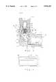
- An example of an expensive, high-quality reusable prophy angleis the TS2TM angle sold by Young Dental Manufacturing Company of Earth City, Mo. This angle is shown in FIG. 1. All of the parts are machined from bronze and stainless steel.
- a body Bterminates in an externally threaded stud B1.
- a drive gear member Dincludes a shaft DS rotatably mounted in an axial bore of the body and a drive gear DG butted against the end of the stud B1.
- a head part His threaded onto the stud B1.
- the head partincludes an axial bore HB and a bore extension HE.
- a post Pis press fitted into the bore extension HE. The post P acts as a thrust bearing for a driven gear Dn.
- the driven gear Dnincludes a gear part DnG and an upwardly-extending internally threaded bur tube DnT.
- a cap Cis threaded into the open end of the head bore and forms radial bearings for the driven gear.
- a stem CS on the outside of the capterminates in an externally beveled knife edge, a short distance above the top of the bur tube.
- Specially designed dental toolssuch as prophy cups manufactured by Young Dental Manufacturing Company, when they are screwed into the bur tube DnT, form a seal with the stem CS and prevent intrusion of material from the patient's mouth into the angle.
- One manner of forming the sealis described in my U.S. Pat. No. 5,484,284.
- One object of the present inventionis to provide a dental prophy angle which need not be lubricated or cleaned of debris during a long useful life.
- Another objectis to provide such an angle which includes an effective means for sealing the angle during use.
- Another objectis to provide such an angle which may be produced so inexpensively that it may be economically replaced after a period of time, such as one year.
- Another objectis to provide such an angle which provides an accurate, simple mounting for its driven gear.
- a maintenance-free dental prophylaxis anglewhich includes a one-piece body including a sleeve and a head.
- the sleeve and headdefine intersecting bores.
- a drive assemblycomprising a drive gear and a bushing, is force fitted into the sleeve, against a rearwardly facing shoulder.
- the drive gearincludes a gear part and a smaller shaft part which extends rearwardly through the bushing and body sleeve.
- the shaftextends slightly beyond the rear end of the prophy angle to be grasped by the collet of a dental handpiece, such as the Doriot nose of an air motor handpiece.
- a driven gearis received in the head bore to be driven by the drive gear.
- the driven gearincludes an upper shaft or bur tube, a gear part, and a lower shaft, all machined from one piece of metal.
- the lower shaftis made sufficiently short to permit machining of gear teeth on the gear part, preferably shorter than the axial height of the gear part.
- the gear part of the driven gearrests on the upper surface of a boss in the head, the boss forming a thrust bearing for the driven gear.
- an arcuate grooveis provided in the upper surface of the boss to prevent the tips of the gear teeth from wearing down the thrust bearing surface.
- a metal capis mounted, preferably force fitted, in the head bore to close the head bore and retain the driven gear in place in the head.
- a dental toolsuch as a prophylaxis cup is connected to the bur tube of the driven gear, and an elastomeric portion of the tool forms a seal with the cap.
- the capincludes a hollow stem surrounding the bur tube, and a knife edge on the hollow stem cuts into an elastomeric ring on the dental tool, in accordance with my previously mentioned U.S. Pat. No. 5,484,284.
- the capforms a tight fit with the body.
- the seal between the dental tool and the capsubstantially prevents foreign material from entering the body and reduces or eliminates the need to clean the interior of the prophy angle.
- the drive gearpreferably includes a gear part and a shaft part machined from a single piece.
- the gear partis larger than the shaft part and is trapped between a forward end of the bushing and a side face of the boss in the head of the angle body to limit axial movement to a few thousandths of an inch.
- the boss in the headincludes a head bore extension which extends substantially beneath the end of the lower shaft of the driven gear and which acts as a lubricant reservoir.
- An aperture in the side wall of the bosscommunicates with the head bore extension and permits lubricant to circulate between a chamber housing the drive gear part and a chamber housing the driven gear part.
- a lubricant which can withstand many autoclaving cycles, such as a lithium grease,is preferably used. The angle thus does not have to be lubricated during its useful life.
- the anglecannot easily be disassembled, and can be used for an extended period of time, for example one year, without requiring any maintenance. Because the construction permits the angle to be produced at low cost, at the end of its useful life the angle can be replaced with a new angle.
- FIG. 1is a cross-sectional view of a prior art TS2 dental prophy angle
- FIG. 2is a cross-sectional view of a dental prophy angle of the present invention
- FIG. 3is an enlarged view of a head and cap assembly of the prophy angle
- FIG. 4is an view of a bushing part of the prophy angle
- FIG. 5is a cross-sectional view of a head portion of the body of the angle
- FIG. 6is a top plan view of the head portion of the body of the angle.
- FIG. 7is a view in front end elevation of the body of the angle.
- FIG. 8is a view in side elevation of the body of the angle
- FIG. 9is an end view of a driven gear of the angle
- FIG. 10is a sectional view of the driven gear of FIG. 9, taken along the line 10--10;
- FIG. 11is a view in side elevation of the cap of the angle.
- FIG. 12is a detail of the cap of FIG. 11, as indicated at 12--12 of FIG. 11.
- Angle 1indicates a preferred embodiment of a dental prophy angle of the present invention.
- Angle 1includes a one-piece metal body 3 having a sleeve 4 with an open back end 5, a neck 6, and a head 7.
- Sleeve 4 and neck 6define an axially extending body bore 9 which receives a drive assembly 11.
- Drive assembly 11includes a bushing 13 and a drive gear 15.
- the bushingpreferably is formed as a cylinder which receives drive gear 15.
- Drive gear 15includes a drive gear part 17 and a rearwardly extending shaft 19.
- Shaft 19is sufficiently long to be received by a handpiece, such as a Doriot type handpiece.
- Shaft 19has a forward section 21 and a rear section 23, having a narrower diameter than the forward section.
- the forward section 21extends back from the drive gear part 17 through the bushing 13.
- the forward shaft section 21includes two spaced apart sections 25 of increased diameter which define bearing surfaces for the drive assembly and a central portion which is smaller in diameter.
- One of the sections 25 of shaft 19extends slightly rearwardly of bushing 13.
- the back surface 29 of gear part 17has a diameter larger than the inner diameter of bushing 13, and abuts the front surface 30 of the bushing 13.
- the surface 30thus acts as a thrust bearing.
- Bore 9includes a reduced diameter section 31 in neck 6 in which bushing 13 is received.
- a yet smaller diameter section 35 at the forward end of bore section 31defines a rearwardly facing shoulder 33 against which the forward face 30 of the bushing 13 abuts.
- the forward end of the body bore section 35is defined by a vertical face 38 of a boss 41.
- a body bore extension 39is provided through face 38 for purposes set out hereinbelow.
- Bushing 13is force fit in neck bore 31 to frictionally maintain the bushing, and hence the drive assembly 11, in place in body 3.
- the bushing 13includes an annular barb 37 at the back thereof.
- the barb 37extends about 0.002" to about 0.004" beyond the outer face of the bushing, to prevent removal of the drive assembly from angle body 3 after the bushing 13 is force fitted into the neck bore 31 as described hereinafter.
- the bushing 13may have a nominal diameter of 0.227", the annular barb 37 a nominal diameter of 0.232", and the neck bore a nominal diameter of 0.229".
- the drive gear part 17is thus constrained against axial movement of more than a few thousandths of an inch by the front face 30 of the bushing 13 and the rear face 38 of the boss 41.
- Head 7is shown in more detail in FIGS. 3-5.
- Head 7is formed integrally with sleeve 4 and includes boss 41 and an upwardly opening bore 43 which defines an upper face 45 of the boss 41.
- Bore 43intersects the forward portion 35 of sleeve bore 9 in a segment 46 at the rear of head bore 43 above the upper face 45 of boss 41.
- An arcuate groove 47extends around the periphery of the upper face 45 of the boss 41.
- a head bore extension 49extends through the upper face 45 of the boss 41 and intersects the body bore extension 39.
- Head bore 43receives a driven gear 50.
- the driven gear 50includes an upper shaft or bur tube 51, a gear part 53, and a lower stub shaft 55, all machined from one piece of metal.
- the bur tube 51is bored and threaded as at 52.
- the lower stub shaft 55is made sufficiently short to permit machining of gear teeth 57 on the lower side of the gear part 53, as shown in FIGS. 3 and 10, without damaging the stub shaft 55.
- the stub shaft 55is shorter than the axial height of the gear part 53. It will be seen that the gear teeth 57 are cut in the form of bevel gears to provide smooth engagement and rotation with similar gear teeth of the drive gear part 17.
- the stub shaft 55is received in bore extension 49 to rotatably mount driven gear 50 in head 7.
- a cap 60(shown in detail in FIGS. 3, 11 and 12) is received in head bore 43 to secure gear 50 in the bore and to prevent axial movement of gear 50 relative to head 7.
- Cap 60includes a trunk 61 which is force fit into cavity 43. Trunk 61 includes barbs 63 to prevent the cap from being removed from the cavity.
- the trunk 61may have a nominal diameter of 0.214", the annular barbs 63 a nominal diameter of 0.218", and the head bore a nominal diameter of 0.216".
- An annular flange 65extends radially outwardly from trunk 61 over the top surface of head 7.
- a stem 67extends upwardly from flange 65. Stem 67 is concentric with, but of a smaller outer diameter than, trunk 61. The upper end of stem 67 is beveled as at 68 to provide a sharp edge.
- Trunk 61 and stem 67have an axial bore 69 which extends therethrough and which is coaxially aligned with head bore 43.
- Bur tube 51 of gear 50extends up through bore 69 to near the top of stem 67.
- Bur tube 51has an outer diameter slightly less than bore 69 so that bur tube 51 may rotate in bore 69.
- bore 69is counter-bored, as at 71, to space a wall 56 of bur tube 51 from counterbore 71.
- cap bore 69 and head bore 49provide bearing means for the driven gear 50.
- a prophy cup 73or other dental tool, is screwed into threaded bore 52 of bur tube 51 to be rotated by the driven gear 50 when the driven gear is rotated by the drive gear.
- Cup 73has a screw 75 which extends downwardly from the base of the cup, to threadedly secure the cup to the gear boss.
- Knife edge 68cuts into an annular bottom surface 82 of cup 73 to form a seal with the cup, as described in U.S. Pat. No. 5,484,284.
- the cup 73is the cup disclosed in that application.
- the body of the angle 1is formed of chrome plated brass, the gears of 303 stainless steel, and the bushing and cap of 440se stainless steel.
- Angle 1is assembled by inserting the drive gear 15 into the bushing 13 to form the drive assembly 11.
- the drive assembly 11is then inserted in angle body 3 by passing it through the back 5 of sleeve 4.
- the assembly 11is pressed into the neck 31 until the front surface 30 of bushing 13 contacts the shoulder 33 in sleeve neck 31.
- the annular barb 37 on bushing 13displaces enough material in the inside of the neck bore 31 to lock the bushing from any axial movement, even when subjected to substantial rearward pull on the shaft 23.
- the driven gear 50is then placed in head bore 43 to mesh with drive gear 17.
- the cap 55is then placed on head 7 by pressing cap trunk 61 into head bore 43 until the bottom of the cap's flange 65 seats against the top face of the head 7.
- the lubricantis preferably a lithium based grease which blends with the molecular structure of the metal components of the angle and does not wear down as readily as other lubricants.
- the head bore extension 49extends substantially beneath the end of the lower shaft of the driven gear and acts as a lubricant reservoir as does the body bore extension 39 which communicates with it.
- the groove 47also acts as a reservoir for lubricant.
- the bore extensions 39 and 49permit lubricant to circulate between the chamber 35 housing the drive gear part and the chamber 43 housing the driven gear part.
- the seal between the cap and the cupprevents foreign material, which could damage the gears, from entering the body.
- the angle 1can therefore be used for a considerable period of time without requiring any maintenance from the dentist or hygienist.
- the fact that the body is molded or cast as a single piecereduces the number of joints in the angle and thus facilitates the reduction in the possibility of foreign matter entering the angle.
- angle bodyis molded, cast, or machined as a single piece, manufacture and assembly of the angle 1 is less expensive than assembly of multi-piece bodies. Further, because the cap 60 and bushing 13 are force fit into the body, rather than being threaded into the body, as is currently done, mating threads on the cap and bushing, and in the body do not have to be formed. This further reduces the cost of manufacturing the angle. Because the angle does not have to be maintained, unlike current metal angles, and because it is less expensive to produce and manufacture than current metal angles, after a period of time, for example one year, the angle 1 can be replaced with a new angle.
- the sleeve 4has a locating slot 91 extending axially a short distance from the back edge of body 3.
- a slit 93is cut into the sleeve at the end of locating slot 91 to be generally perpendicular to slot 91 and generally parallel to the plane of the back 5 of the angle.
- the slit 93creates two spring fingers 94 which expand slightly when the angle is placed on a handpiece. This creates a size-on-size frictional fit with the nose of the handpiece and to hold the angle body angularly and axially with respect to the handpiece independently of the shaft being held by the handpiece chuck, as is standard in the art.
- the bodyis provided with two shallow axially extending linear depressions 95 which give the user better rotational control of the angle 1, but which permit easy cleaning of the surface of the body 3.
- the bore in the head of the bodymay be internally threaded and the cap externally threaded to provide a prophy angle in which the cap can be removed for cleaning and lubricating the driven gear and its chamber.
- the bodymay be formed of a suitable plastic which can withstand repeated autoclave cycles, as can the drive gear.
- the cap and the driven gearare formed of materials which can retain the sharpness of the edge of the stem and the critical axial dimension and internal threading of the bur tube.
- the capmay be provided with a protective wall around its hollow stem, as described in my U.S. Pat.
Landscapes
- Health & Medical Sciences (AREA)
- Oral & Maxillofacial Surgery (AREA)
- Dentistry (AREA)
- Epidemiology (AREA)
- Life Sciences & Earth Sciences (AREA)
- Animal Behavior & Ethology (AREA)
- General Health & Medical Sciences (AREA)
- Public Health (AREA)
- Veterinary Medicine (AREA)
- Dental Tools And Instruments Or Auxiliary Dental Instruments (AREA)
Abstract
Description
Claims (25)
Priority Applications (1)
| Application Number | Priority Date | Filing Date | Title |
|---|---|---|---|
| US08/960,852US5876203A (en) | 1995-08-16 | 1997-10-30 | Permanently lubricated dental prophylaxis angle |
Applications Claiming Priority (2)
| Application Number | Priority Date | Filing Date | Title |
|---|---|---|---|
| US08/515,825US5683247A (en) | 1995-08-16 | 1995-08-16 | Permanently lubricated dental prophylaxis angle |
| US08/960,852US5876203A (en) | 1995-08-16 | 1997-10-30 | Permanently lubricated dental prophylaxis angle |
Related Parent Applications (1)
| Application Number | Title | Priority Date | Filing Date |
|---|---|---|---|
| US08/515,825ContinuationUS5683247A (en) | 1995-08-16 | 1995-08-16 | Permanently lubricated dental prophylaxis angle |
Publications (1)
| Publication Number | Publication Date |
|---|---|
| US5876203Atrue US5876203A (en) | 1999-03-02 |
Family
ID=24052915
Family Applications (2)
| Application Number | Title | Priority Date | Filing Date |
|---|---|---|---|
| US08/515,825Expired - LifetimeUS5683247A (en) | 1995-08-16 | 1995-08-16 | Permanently lubricated dental prophylaxis angle |
| US08/960,852Expired - LifetimeUS5876203A (en) | 1995-08-16 | 1997-10-30 | Permanently lubricated dental prophylaxis angle |
Family Applications Before (1)
| Application Number | Title | Priority Date | Filing Date |
|---|---|---|---|
| US08/515,825Expired - LifetimeUS5683247A (en) | 1995-08-16 | 1995-08-16 | Permanently lubricated dental prophylaxis angle |
Country Status (1)
| Country | Link |
|---|---|
| US (2) | US5683247A (en) |
Cited By (15)
| Publication number | Priority date | Publication date | Assignee | Title |
|---|---|---|---|---|
| US6257886B1 (en) | 1998-06-23 | 2001-07-10 | Thomas P. Warner | Disposable dental prophylaxis angle |
| US20040014004A1 (en)* | 2002-07-22 | 2004-01-22 | Thomas Garrison | Dental apparatus |
| US20050061523A1 (en)* | 2003-09-22 | 2005-03-24 | Richard Bader | Hand machine tool |
| FR2865127A1 (en)* | 2004-01-19 | 2005-07-22 | Sirona Dental Systems Gmbh | INSERT FOR A DENTIST HAND INSTRUMENT, ESPECIALLY FOR PROPHYLACTIC TREATMENT |
| US20060210948A1 (en)* | 2005-03-14 | 2006-09-21 | Rose Eric P | Prophylaxis angles and cups |
| US20070026361A1 (en)* | 2005-07-26 | 2007-02-01 | Carron Chris J | Prophy angle |
| US20080064007A1 (en)* | 2005-07-26 | 2008-03-13 | Carron Chris J | Prophy angle and adapter |
| US20090081610A1 (en)* | 2007-09-14 | 2009-03-26 | Discus Dental, Llc | Dental prophylaxis devices |
| US20090088770A1 (en)* | 2007-10-01 | 2009-04-02 | Warsaw Orthopedic, Inc. | Angled surgical drivers and methods of use |
| US20090162811A1 (en)* | 2007-12-20 | 2009-06-25 | Benjamin Chronister | Dental prophylaxis angle and handpiece assembly |
| USD674487S1 (en) | 2011-09-30 | 2013-01-15 | Dentsply International Inc. | Dental device connection adapter |
| US20130112730A1 (en)* | 2007-09-21 | 2013-05-09 | Covidien Lp | Surgical device having a rotatable jaw portion |
| USD687552S1 (en) | 2011-09-30 | 2013-08-06 | Dentsply International Inc. | Dental device connection adapter |
| US20170312050A1 (en)* | 2015-06-11 | 2017-11-02 | Avid, Inc. | Dental Handpiece and Prophy Angle |
| USD1013873S1 (en) | 2022-06-17 | 2024-02-06 | Young Dental Manufacturing I, Llc | Prophy angle body |
Families Citing this family (12)
| Publication number | Priority date | Publication date | Assignee | Title |
|---|---|---|---|---|
| US5683247A (en)* | 1995-08-16 | 1997-11-04 | Young Dental Manufacturing Company | Permanently lubricated dental prophylaxis angle |
| US5964590A (en)* | 1998-03-14 | 1999-10-12 | Young Dental Manufacturing Company | Permanently lubricated dental prophylaxis angle |
| US6203322B1 (en) | 1999-04-15 | 2001-03-20 | David Kraenzle | Dental prophylaxis angle |
| EP1349511A2 (en)* | 2000-12-18 | 2003-10-08 | Dentsply International, Inc. | Dental handpiece |
| US6655015B2 (en)* | 2001-03-30 | 2003-12-02 | David G. Kraenzle | DPA automated assembly and packaging machine |
| US6527552B2 (en)* | 2001-06-13 | 2003-03-04 | Young Dental Manufacturing I, L.L.C. | Lubricated disposable prophylaxis angle |
| DE102011050191A1 (en)* | 2011-05-06 | 2012-11-08 | Aesculap Ag | Surgical handpiece |
| USD776814S1 (en) | 2015-06-11 | 2017-01-17 | Avid, Inc. | Dental prophy angle nosecone attachment feature |
| USD776815S1 (en) | 2015-06-11 | 2017-01-17 | Avid, Inc. | Dental handpiece nosecone |
| EP3427691B1 (en) | 2017-07-14 | 2019-12-04 | W & H Dentalwerk Bürmoos GmbH | Dental prophylaxis-treatment unit |
| US11033096B2 (en)* | 2017-12-12 | 2021-06-15 | Colgate-Palmolive Company | Oral care refill head and oral care kit including the same |
| CN216777251U (en)* | 2021-12-29 | 2022-06-21 | 谭锦辉 | Dental polishing bent angle |
Citations (13)
| Publication number | Priority date | Publication date | Assignee | Title |
|---|---|---|---|---|
| US2098317A (en)* | 1935-09-19 | 1937-11-09 | Staunt Martin | Dental appliance |
| US3163934A (en)* | 1962-09-14 | 1965-01-05 | Adolph D Wiseman | Dental prophylaxis right angle hand piece |
| US3407502A (en)* | 1965-11-19 | 1968-10-29 | George E. Richmond | Tooth cleaning apparatus |
| US3478433A (en)* | 1968-04-15 | 1969-11-18 | George E Richmond | Tooth cleaning tool |
| US4182041A (en)* | 1976-12-22 | 1980-01-08 | Girard, Inc. | Dental prophylactic right angle hand piece |
| US4292027A (en)* | 1979-07-23 | 1981-09-29 | Young Dental Manufacturing Co. | Sealing dental collet |
| US4365956A (en)* | 1978-10-23 | 1982-12-28 | Young Dental Manufacturing Company | Cleaning cup |
| US4486175A (en)* | 1982-11-01 | 1984-12-04 | Teledyne Industries, Inc. | Dental appliance |
| US5062796A (en)* | 1990-07-17 | 1991-11-05 | Rosenberg Neil A | Dental handpiece |
| US5160263A (en)* | 1990-03-30 | 1992-11-03 | Moshe Meller | Disposable right angle dental handpiece |
| US5484284A (en)* | 1994-07-28 | 1996-01-16 | Young Dental Manufacturing Company, Inc. | Dental prophylaxis tool and angle using it |
| US5642995A (en)* | 1995-08-16 | 1997-07-01 | Young Dental Manufacturing Company | Dental prophylaxis angle with seal protector |
| US5683247A (en)* | 1995-08-16 | 1997-11-04 | Young Dental Manufacturing Company | Permanently lubricated dental prophylaxis angle |
- 1995
- 1995-08-16USUS08/515,825patent/US5683247A/ennot_activeExpired - Lifetime
- 1997
- 1997-10-30USUS08/960,852patent/US5876203A/ennot_activeExpired - Lifetime
Patent Citations (13)
| Publication number | Priority date | Publication date | Assignee | Title |
|---|---|---|---|---|
| US2098317A (en)* | 1935-09-19 | 1937-11-09 | Staunt Martin | Dental appliance |
| US3163934A (en)* | 1962-09-14 | 1965-01-05 | Adolph D Wiseman | Dental prophylaxis right angle hand piece |
| US3407502A (en)* | 1965-11-19 | 1968-10-29 | George E. Richmond | Tooth cleaning apparatus |
| US3478433A (en)* | 1968-04-15 | 1969-11-18 | George E Richmond | Tooth cleaning tool |
| US4182041A (en)* | 1976-12-22 | 1980-01-08 | Girard, Inc. | Dental prophylactic right angle hand piece |
| US4365956A (en)* | 1978-10-23 | 1982-12-28 | Young Dental Manufacturing Company | Cleaning cup |
| US4292027A (en)* | 1979-07-23 | 1981-09-29 | Young Dental Manufacturing Co. | Sealing dental collet |
| US4486175A (en)* | 1982-11-01 | 1984-12-04 | Teledyne Industries, Inc. | Dental appliance |
| US5160263A (en)* | 1990-03-30 | 1992-11-03 | Moshe Meller | Disposable right angle dental handpiece |
| US5062796A (en)* | 1990-07-17 | 1991-11-05 | Rosenberg Neil A | Dental handpiece |
| US5484284A (en)* | 1994-07-28 | 1996-01-16 | Young Dental Manufacturing Company, Inc. | Dental prophylaxis tool and angle using it |
| US5642995A (en)* | 1995-08-16 | 1997-07-01 | Young Dental Manufacturing Company | Dental prophylaxis angle with seal protector |
| US5683247A (en)* | 1995-08-16 | 1997-11-04 | Young Dental Manufacturing Company | Permanently lubricated dental prophylaxis angle |
Non-Patent Citations (2)
| Title |
|---|
| Young Dental Manufacturing Company, "C-Model Head Ass'y" (6 pages) (1975). |
| Young Dental Manufacturing Company, C Model Head Ass y (6 pages) (1975).* |
Cited By (26)
| Publication number | Priority date | Publication date | Assignee | Title |
|---|---|---|---|---|
| US6257886B1 (en) | 1998-06-23 | 2001-07-10 | Thomas P. Warner | Disposable dental prophylaxis angle |
| US7101182B2 (en) | 2002-07-22 | 2006-09-05 | Garrison Dental Solutions | Dental apparatus |
| US20040014004A1 (en)* | 2002-07-22 | 2004-01-22 | Thomas Garrison | Dental apparatus |
| US20050061523A1 (en)* | 2003-09-22 | 2005-03-24 | Richard Bader | Hand machine tool |
| FR2865127A1 (en)* | 2004-01-19 | 2005-07-22 | Sirona Dental Systems Gmbh | INSERT FOR A DENTIST HAND INSTRUMENT, ESPECIALLY FOR PROPHYLACTIC TREATMENT |
| US20060210948A1 (en)* | 2005-03-14 | 2006-09-21 | Rose Eric P | Prophylaxis angles and cups |
| US8123523B2 (en) | 2005-07-26 | 2012-02-28 | Angstrom Manufacturing, Inc. | Prophy angle and adapter |
| US20080064007A1 (en)* | 2005-07-26 | 2008-03-13 | Carron Chris J | Prophy angle and adapter |
| US7422433B2 (en) | 2005-07-26 | 2008-09-09 | Angstrom Manufacturing, Inc. | Prophy angle |
| US20070026361A1 (en)* | 2005-07-26 | 2007-02-01 | Carron Chris J | Prophy angle |
| US20080311541A1 (en)* | 2005-07-26 | 2008-12-18 | Angstrom Manufacturing, Inc. | Prophy angle |
| US8360774B2 (en) | 2005-07-26 | 2013-01-29 | Angstrom Manufacturing, Inc. | Prophy angle |
| US20090081610A1 (en)* | 2007-09-14 | 2009-03-26 | Discus Dental, Llc | Dental prophylaxis devices |
| US8777615B2 (en) | 2007-09-14 | 2014-07-15 | Robert Hayman | Dental prophylaxis devices |
| US10881397B2 (en) | 2007-09-21 | 2021-01-05 | Covidien Lp | Surgical device having a rotatable jaw portion |
| US10117651B2 (en) | 2007-09-21 | 2018-11-06 | Covidien Lp | Surgical device having a rotatable jaw portion |
| US20130112730A1 (en)* | 2007-09-21 | 2013-05-09 | Covidien Lp | Surgical device having a rotatable jaw portion |
| US9204877B2 (en)* | 2007-09-21 | 2015-12-08 | Covidien Lp | Surgical device having a rotatable jaw portion |
| US20090088770A1 (en)* | 2007-10-01 | 2009-04-02 | Warsaw Orthopedic, Inc. | Angled surgical drivers and methods of use |
| US20090162811A1 (en)* | 2007-12-20 | 2009-06-25 | Benjamin Chronister | Dental prophylaxis angle and handpiece assembly |
| US7955079B2 (en) | 2007-12-20 | 2011-06-07 | Dentsply International, Inc. | Dental prophylaxis angle and handpiece assembly |
| USD687552S1 (en) | 2011-09-30 | 2013-08-06 | Dentsply International Inc. | Dental device connection adapter |
| USD674487S1 (en) | 2011-09-30 | 2013-01-15 | Dentsply International Inc. | Dental device connection adapter |
| US20170312050A1 (en)* | 2015-06-11 | 2017-11-02 | Avid, Inc. | Dental Handpiece and Prophy Angle |
| US10765491B2 (en)* | 2015-06-11 | 2020-09-08 | Avid, Inc. | Dental handpiece and prophy angle |
| USD1013873S1 (en) | 2022-06-17 | 2024-02-06 | Young Dental Manufacturing I, Llc | Prophy angle body |
Also Published As
| Publication number | Publication date |
|---|---|
| US5683247A (en) | 1997-11-04 |
Similar Documents
| Publication | Publication Date | Title |
|---|---|---|
| US5876203A (en) | Permanently lubricated dental prophylaxis angle | |
| US5964590A (en) | Permanently lubricated dental prophylaxis angle | |
| US5749728A (en) | Method of assembling a dental prophylaxis angle | |
| US5156547A (en) | Disposable prophylaxis angle and method of assembling | |
| US4365956A (en) | Cleaning cup | |
| US5531599A (en) | Disposable dental prophylaxis contra-angle, method of making it, and drive gear for use therein | |
| US6099309A (en) | Disposable prophy angle | |
| US5484284A (en) | Dental prophylaxis tool and angle using it | |
| US3727313A (en) | Dental prophylaxis right angle hand piece | |
| US5704786A (en) | Chuck with a push button release for a dental/medical device | |
| US5064373A (en) | Plug forming removable closure in openings of dental appliances and the like | |
| US7160108B2 (en) | All-in-one prophy angle | |
| US5924865A (en) | Chuck with a push button release for a dental/medical device | |
| US3324553A (en) | Dental handpiece | |
| WO1997006745A1 (en) | Dental prophylaxis angle with seal protector | |
| US5160263A (en) | Disposable right angle dental handpiece | |
| US20060046227A1 (en) | Disposable dental prophy angle with secure retention mechanism | |
| US2813337A (en) | Holder for rotatable tools | |
| USRE30340E (en) | Dental handpiece | |
| US4253832A (en) | Dental handpiece | |
| JP2001204740A (en) | Medical cutting instruments and sealing members for medical cutting instruments | |
| US2911721A (en) | Contra angles for dental handpieces | |
| US2923060A (en) | Dental handpieces | |
| JP7251826B2 (en) | dental handpiece | |
| JPH10277806A (en) | Rolling center |
Legal Events
| Date | Code | Title | Description |
|---|---|---|---|
| STCF | Information on status: patent grant | Free format text:PATENTED CASE | |
| AS | Assignment | Owner name:YOUNG DENTAL MANUFACTURING COMPANY 1 LLC, MISSOURI Free format text:MERGER;ASSIGNOR:YOUNG DENTAL MANUFACTURING COMPANY;REEL/FRAME:012935/0369 Effective date:20011005 | |
| FPAY | Fee payment | Year of fee payment:4 | |
| FPAY | Fee payment | Year of fee payment:8 | |
| FPAY | Fee payment | Year of fee payment:12 | |
| AS | Assignment | Owner name:YOUNG DENTAL MANUFACTURING I, LLC, MISSOURI Free format text:CORRECTION OF THE SPELLING OF NAME OF THE RECEIVING PARTY (BOX 2) AND THE EXECUTION DATE (BOX 3) IN THE COVER SHEET FOR THE MERGER RECORDED AT REEL/FRAME 012935/0369;ASSIGNOR:YOUNG DENTAL MANUFACTURING COMPANY;REEL/FRAME:029682/0489 Effective date:19991112 | |
| AS | Assignment | Owner name:MADISON CAPITAL FUNDING LLC, ILLINOIS Free format text:SECURITY AGREEMENT;ASSIGNOR:YOUNG DENTAL MANUFACTURING I, LLC;REEL/FRAME:029759/0777 Effective date:20120131 | |
| AS | Assignment | Owner name:ARES CAPITAL CORPORATION, AS AGENT, NEW YORK Free format text:SECOND LIEN PATENT SECURITY AGREEMENT;ASSIGNOR:YOUNG DENTAL MANUFACTURING I, LLC;REEL/FRAME:033086/0412 Effective date:20140530 | |
| AS | Assignment | Owner name:GOLUB CAPITAL MARKETS LLC, ILLINOIS Free format text:SECURITY INTEREST;ASSIGNOR:YOUNG DENTAL MANUFACTURING I, LLC;REEL/FRAME:040049/0718 Effective date:20161018 | |
| AS | Assignment | Owner name:YOUNG PS ACQUISITIONS, LLC, ILLINOIS Free format text:RELEASE BY SECURED PARTY;ASSIGNOR:ARES CAPITAL CORPORATION;REEL/FRAME:044392/0196 Effective date:20171107 Owner name:YOUNG INNOVATIONS, INC., ILLINOIS Free format text:RELEASE BY SECURED PARTY;ASSIGNOR:ARES CAPITAL CORPORATION;REEL/FRAME:044392/0196 Effective date:20171107 Owner name:AMERICAN EAGLE INSTRUMENTS, LLC, ILLINOIS Free format text:RELEASE BY SECURED PARTY;ASSIGNOR:ARES CAPITAL CORPORATION;REEL/FRAME:044392/0196 Effective date:20171107 Owner name:YOUNG MICROBRUSH, LLC, ILLINOIS Free format text:RELEASE BY SECURED PARTY;ASSIGNOR:ARES CAPITAL CORPORATION;REEL/FRAME:044392/0196 Effective date:20171107 Owner name:YOUNG DENTAL MANUFACTURING, LLC, ILLINOIS Free format text:RELEASE BY SECURED PARTY;ASSIGNOR:ARES CAPITAL CORPORATION;REEL/FRAME:044392/0196 Effective date:20171107 Owner name:YOUNG OS LLC, ILLINOIS Free format text:RELEASE BY SECURED PARTY;ASSIGNOR:ARES CAPITAL CORPORATION;REEL/FRAME:044392/0196 Effective date:20171107 Owner name:YOUNG MICROBRUSH, LLC, ILLINOIS Free format text:RELEASE BY SECURED PARTY;ASSIGNOR:GOLUB CAPITAL MARKETS LLC;REEL/FRAME:044392/0353 Effective date:20171107 Owner name:YOUNG DENTAL MANUFACTURING, LLC, ILLINOIS Free format text:RELEASE BY SECURED PARTY;ASSIGNOR:GOLUB CAPITAL MARKETS LLC;REEL/FRAME:044392/0353 Effective date:20171107 Owner name:YOUNG PS ACQUISITIONS, LLC, ILLINOIS Free format text:RELEASE BY SECURED PARTY;ASSIGNOR:GOLUB CAPITAL MARKETS LLC;REEL/FRAME:044392/0353 Effective date:20171107 Owner name:YI VENTURES LLC, ILLINOIS Free format text:RELEASE BY SECURED PARTY;ASSIGNOR:GOLUB CAPITAL MARKETS LLC;REEL/FRAME:044392/0353 Effective date:20171107 Owner name:YOUNG COLORADO, LLC, COLORADO Free format text:RELEASE BY SECURED PARTY;ASSIGNOR:GOLUB CAPITAL MARKETS LLC;REEL/FRAME:044392/0353 Effective date:20171107 Owner name:AMERICAN EAGLE INSTRUMENTS, LLC, ILLINOIS Free format text:RELEASE BY SECURED PARTY;ASSIGNOR:GOLUB CAPITAL MARKETS LLC;REEL/FRAME:044392/0353 Effective date:20171107 Owner name:YOUNG INNOVATIONS, INC., ILLINOIS Free format text:RELEASE BY SECURED PARTY;ASSIGNOR:GOLUB CAPITAL MARKETS LLC;REEL/FRAME:044392/0353 Effective date:20171107 Owner name:YOUNG OS LLC, ILLINOIS Free format text:RELEASE BY SECURED PARTY;ASSIGNOR:GOLUB CAPITAL MARKETS LLC;REEL/FRAME:044392/0353 Effective date:20171107 |