US5876008A - Suspension system for video monitor or other equipment - Google Patents
Suspension system for video monitor or other equipmentDownload PDFInfo
- Publication number
- US5876008A US5876008AUS08/372,948US37294895AUS5876008AUS 5876008 AUS5876008 AUS 5876008AUS 37294895 AUS37294895 AUS 37294895AUS 5876008 AUS5876008 AUS 5876008A
- Authority
- US
- United States
- Prior art keywords
- suspension system
- bracket
- angled arm
- vertical
- major
- Prior art date
- Legal status (The legal status is an assumption and is not a legal conclusion. Google has not performed a legal analysis and makes no representation as to the accuracy of the status listed.)
- Expired - Lifetime
Links
- 239000000725suspensionSubstances0.000titleclaimsabstractdescription64
- 229920000642polymerPolymers0.000claimsdescription4
- 239000004699Ultra-high molecular weight polyethyleneSubstances0.000claimsdescription3
- 229920000785ultra high molecular weight polyethylenePolymers0.000claimsdescription3
- 239000002184metalSubstances0.000claimsdescription2
- 229910052751metalInorganic materials0.000claimsdescription2
- 230000003068static effectEffects0.000claimsdescription2
- 230000006835compressionEffects0.000claims1
- 238000007906compressionMethods0.000claims1
- 229910000831SteelInorganic materials0.000description5
- 239000004033plasticSubstances0.000description5
- 229920003023plasticPolymers0.000description5
- 125000006850spacer groupChemical group0.000description5
- 239000010959steelSubstances0.000description5
- 239000000463materialSubstances0.000description4
- 230000006870functionEffects0.000description2
- 239000003351stiffenerSubstances0.000description2
- 229910000906BronzeInorganic materials0.000description1
- 150000001336alkenesChemical class0.000description1
- 229910052782aluminiumInorganic materials0.000description1
- XAGFODPZIPBFFR-UHFFFAOYSA-NaluminiumChemical compound[Al]XAGFODPZIPBFFR-UHFFFAOYSA-N0.000description1
- 239000010974bronzeSubstances0.000description1
- 239000002131composite materialSubstances0.000description1
- KUNSUQLRTQLHQQ-UHFFFAOYSA-Ncopper tinChemical compound[Cu].[Sn]KUNSUQLRTQLHQQ-UHFFFAOYSA-N0.000description1
- 230000008030eliminationEffects0.000description1
- 238000003379elimination reactionMethods0.000description1
- 230000004438eyesightEffects0.000description1
- 238000010348incorporationMethods0.000description1
- 238000012986modificationMethods0.000description1
- 230000004048modificationEffects0.000description1
- JRZJOMJEPLMPRA-UHFFFAOYSA-NolefinNatural productsCCCCCCCC=CJRZJOMJEPLMPRA-UHFFFAOYSA-N0.000description1
- 238000003466weldingMethods0.000description1
Images


Classifications
- F—MECHANICAL ENGINEERING; LIGHTING; HEATING; WEAPONS; BLASTING
- F16—ENGINEERING ELEMENTS AND UNITS; GENERAL MEASURES FOR PRODUCING AND MAINTAINING EFFECTIVE FUNCTIONING OF MACHINES OR INSTALLATIONS; THERMAL INSULATION IN GENERAL
- F16M—FRAMES, CASINGS OR BEDS OF ENGINES, MACHINES OR APPARATUS, NOT SPECIFIC TO ENGINES, MACHINES OR APPARATUS PROVIDED FOR ELSEWHERE; STANDS; SUPPORTS
- F16M13/00—Other supports for positioning apparatus or articles; Means for steadying hand-held apparatus or articles
- F16M13/02—Other supports for positioning apparatus or articles; Means for steadying hand-held apparatus or articles for supporting on, or attaching to, an object, e.g. tree, gate, window-frame, cycle
- F—MECHANICAL ENGINEERING; LIGHTING; HEATING; WEAPONS; BLASTING
- F16—ENGINEERING ELEMENTS AND UNITS; GENERAL MEASURES FOR PRODUCING AND MAINTAINING EFFECTIVE FUNCTIONING OF MACHINES OR INSTALLATIONS; THERMAL INSULATION IN GENERAL
- F16M—FRAMES, CASINGS OR BEDS OF ENGINES, MACHINES OR APPARATUS, NOT SPECIFIC TO ENGINES, MACHINES OR APPARATUS PROVIDED FOR ELSEWHERE; STANDS; SUPPORTS
- F16M11/00—Stands or trestles as supports for apparatus or articles placed thereon ; Stands for scientific apparatus such as gravitational force meters
- F16M11/02—Heads
- F16M11/04—Means for attachment of apparatus; Means allowing adjustment of the apparatus relatively to the stand
- F16M11/06—Means for attachment of apparatus; Means allowing adjustment of the apparatus relatively to the stand allowing pivoting
- F16M11/08—Means for attachment of apparatus; Means allowing adjustment of the apparatus relatively to the stand allowing pivoting around a vertical axis, e.g. panoramic heads
- F—MECHANICAL ENGINEERING; LIGHTING; HEATING; WEAPONS; BLASTING
- F16—ENGINEERING ELEMENTS AND UNITS; GENERAL MEASURES FOR PRODUCING AND MAINTAINING EFFECTIVE FUNCTIONING OF MACHINES OR INSTALLATIONS; THERMAL INSULATION IN GENERAL
- F16M—FRAMES, CASINGS OR BEDS OF ENGINES, MACHINES OR APPARATUS, NOT SPECIFIC TO ENGINES, MACHINES OR APPARATUS PROVIDED FOR ELSEWHERE; STANDS; SUPPORTS
- F16M11/00—Stands or trestles as supports for apparatus or articles placed thereon ; Stands for scientific apparatus such as gravitational force meters
- F16M11/20—Undercarriages with or without wheels
- F16M11/2007—Undercarriages with or without wheels comprising means allowing pivoting adjustment
- F16M11/2021—Undercarriages with or without wheels comprising means allowing pivoting adjustment around a horizontal axis
- F—MECHANICAL ENGINEERING; LIGHTING; HEATING; WEAPONS; BLASTING
- F16—ENGINEERING ELEMENTS AND UNITS; GENERAL MEASURES FOR PRODUCING AND MAINTAINING EFFECTIVE FUNCTIONING OF MACHINES OR INSTALLATIONS; THERMAL INSULATION IN GENERAL
- F16M—FRAMES, CASINGS OR BEDS OF ENGINES, MACHINES OR APPARATUS, NOT SPECIFIC TO ENGINES, MACHINES OR APPARATUS PROVIDED FOR ELSEWHERE; STANDS; SUPPORTS
- F16M2200/00—Details of stands or supports
- F16M2200/04—Balancing means
- F16M2200/044—Balancing means for balancing rotational movement of the undercarriage
- F—MECHANICAL ENGINEERING; LIGHTING; HEATING; WEAPONS; BLASTING
- F16—ENGINEERING ELEMENTS AND UNITS; GENERAL MEASURES FOR PRODUCING AND MAINTAINING EFFECTIVE FUNCTIONING OF MACHINES OR INSTALLATIONS; THERMAL INSULATION IN GENERAL
- F16M—FRAMES, CASINGS OR BEDS OF ENGINES, MACHINES OR APPARATUS, NOT SPECIFIC TO ENGINES, MACHINES OR APPARATUS PROVIDED FOR ELSEWHERE; STANDS; SUPPORTS
- F16M2200/00—Details of stands or supports
- F16M2200/06—Arms
- F16M2200/068—Arms being part of the undercarriage
- Y—GENERAL TAGGING OF NEW TECHNOLOGICAL DEVELOPMENTS; GENERAL TAGGING OF CROSS-SECTIONAL TECHNOLOGIES SPANNING OVER SEVERAL SECTIONS OF THE IPC; TECHNICAL SUBJECTS COVERED BY FORMER USPC CROSS-REFERENCE ART COLLECTIONS [XRACs] AND DIGESTS
- Y10—TECHNICAL SUBJECTS COVERED BY FORMER USPC
- Y10S—TECHNICAL SUBJECTS COVERED BY FORMER USPC CROSS-REFERENCE ART COLLECTIONS [XRACs] AND DIGESTS
- Y10S248/00—Supports
- Y10S248/917—Video display screen support
- Y10S248/919—Adjustably orientable video screen support
Definitions
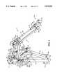
- FIG. 1is an isometric view of a suspension system 10 of the present invention.
- a one-piece angled arm 12constructed of rectangular tubing is pivotally secured at one end to a major bracket 14 of steel or aluminum channel.
- the vertically aligned major bracket 14includes a planar back member 14b and opposing planar side members 14a and 14c extending perpendicularly from the common planar back member 14b.
- the one-piece angled arm 12includes straight portions 12a and 12c aligned at angles to each other with an intermediate curved portion 12b located therebetween.
- the inboard end of the straight arm portion 12aaligns with and is secured such as by a weldment to a horizontally aligned pivot tube 16.
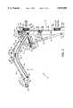
- a plurality of machine screws 119a-119n or other suitable fastenersextend through like and similar slots 119 and 121 in each of the bracket support plates 122a and 124a of adjustable angled brackets 122 and 124 to adjust the rubber bumpers 118 and 120 inwardly or outwardly and thereby adjust the amount of arcuate travel of the major bracket 14, angled arm 12, and associated components, including a tilt and swivel mount from which a caddy carrying a video monitor is suspended.
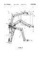
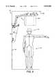
- FIG. 8illustrates the range of vertical movement of the angled arm 12. Ranges vary from an upper and automatically locked position 152 to a lower and lockable position 154, and also a variety of intermediate positions illustrated as mid-position 156.
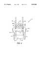
- a tilt and swivel mount 160illustrated in FIGS. 11 and 12, and previously referenced, is secured and aligned in the bearing mount 30 for suspension of a caddy 162 and a monitor 164, shown in dashed lines.
Landscapes
- Engineering & Computer Science (AREA)
- General Engineering & Computer Science (AREA)
- Mechanical Engineering (AREA)
- Devices For Indicating Variable Information By Combining Individual Elements (AREA)
- Details Of Measuring And Other Instruments (AREA)
Abstract
Description
Claims (40)
Priority Applications (4)
| Application Number | Priority Date | Filing Date | Title |
|---|---|---|---|
| US08/372,948US5876008A (en) | 1995-01-17 | 1995-01-17 | Suspension system for video monitor or other equipment |
| CA002166375ACA2166375A1 (en) | 1995-01-17 | 1995-12-29 | Video monitor suspension system |
| EP96300290AEP0723368A3 (en) | 1995-01-17 | 1996-01-16 | Video monitor suspension system |
| JP8006146AJPH08317319A (en) | 1995-01-17 | 1996-01-17 | Video monitor suspension device |
Applications Claiming Priority (1)
| Application Number | Priority Date | Filing Date | Title |
|---|---|---|---|
| US08/372,948US5876008A (en) | 1995-01-17 | 1995-01-17 | Suspension system for video monitor or other equipment |
Publications (1)
| Publication Number | Publication Date |
|---|---|
| US5876008Atrue US5876008A (en) | 1999-03-02 |
Family
ID=23470281
Family Applications (1)
| Application Number | Title | Priority Date | Filing Date |
|---|---|---|---|
| US08/372,948Expired - LifetimeUS5876008A (en) | 1995-01-17 | 1995-01-17 | Suspension system for video monitor or other equipment |
Country Status (4)
| Country | Link |
|---|---|
| US (1) | US5876008A (en) |
| EP (1) | EP0723368A3 (en) |
| JP (1) | JPH08317319A (en) |
| CA (1) | CA2166375A1 (en) |
Cited By (107)
| Publication number | Priority date | Publication date | Assignee | Title |
|---|---|---|---|---|
| US6213438B1 (en)* | 1999-12-16 | 2001-04-10 | Ostby Leroy M. | Computer support for vehicle use having multiple position adjustments |
| US20020079415A1 (en)* | 1999-06-07 | 2002-06-27 | Oddsen Odd N. | Arm apparatus for mounting electronic devices |
| US6419196B1 (en)* | 1996-06-07 | 2002-07-16 | Ergotron, Inc. | Pivot assembly and support system |
| US20030052787A1 (en)* | 2001-08-03 | 2003-03-20 | Zerhusen Robert Mark | Patient point-of-care computer system |
| US20030076976A1 (en)* | 2001-02-02 | 2003-04-24 | Mikio Fukuda | Microphone with arm |
| US6553587B1 (en)* | 2001-10-25 | 2003-04-29 | Ge Medical Systems Global Technology Company, Llc | Method and apparatus for alignment and orientation of a monitor in a patient support system |
| USD477325S1 (en) | 2002-04-24 | 2003-07-15 | Ergotron, Inc. | Support for flat panel monitor display unit |
| USD477606S1 (en) | 2002-04-24 | 2003-07-22 | Ergotron, Inc. | Support for flat panel monitor display unit |
| US20030223188A1 (en)* | 2002-05-28 | 2003-12-04 | Samsung Electronics Co., Ltd. | Tilting apparatus of monitor |
| US20030234328A1 (en)* | 1999-06-07 | 2003-12-25 | Innovative Office Products, Inc. | Arm apparatus for mounting electronic devices with cable management system |
| US20040004170A1 (en)* | 1999-05-10 | 2004-01-08 | Innovative Office Products, Inc. | Arm apparatus for mounting electronic devices |
| US20040004165A1 (en)* | 2002-07-06 | 2004-01-08 | Samsung Electronics Co., Ltd. | Display apparatus |
| US20040012917A1 (en)* | 2002-07-16 | 2004-01-22 | Samsung Electronics Co., Ltd. | Monitor improved in a tilting structure |
| US20040035989A1 (en)* | 2002-08-21 | 2004-02-26 | Sweere Harry C. | Stand |
| US20040084579A1 (en)* | 2002-10-30 | 2004-05-06 | Samsung Electronics Co., Ltd. | Stand for display |
| US20040084578A1 (en)* | 2002-11-05 | 2004-05-06 | Samsung Electronics, Co., Ltd. | Display apparatus |
| US20040118984A1 (en)* | 2002-09-27 | 2004-06-24 | Samsung Electronics Co., Ltd. | Display apparatus |
| US20040147178A1 (en)* | 2002-11-11 | 2004-07-29 | Samsung Electronics Co., Ltd. | Monitor |
| US6783105B2 (en) | 2001-06-20 | 2004-08-31 | Innovative Office Products, Inc. | Adjustable display arm for computer components |
| US20040211866A1 (en)* | 2001-11-19 | 2004-10-28 | Samsung Electronics Co., Ltd. | Monitor improved in a tilting and combining structure |
| US20040231213A1 (en)* | 2003-05-23 | 2004-11-25 | Samsung Electronic Co., Ltd. | Display apparatus |
| US20040250635A1 (en)* | 2003-05-20 | 2004-12-16 | Sweere Harry C. | Lift mechanism based on torque equalization principles |
| US20040262474A1 (en)* | 2003-04-22 | 2004-12-30 | Boks Michael J. | Flat screen monitor support system |
| US20050002159A1 (en)* | 2002-09-28 | 2005-01-06 | Samsung Electronics Co., Ltd. | Monitor |
| US20050034547A1 (en)* | 2003-08-01 | 2005-02-17 | Sweere Harry C. | Mechanisms based on torque equalization principles |
| US20050139734A1 (en)* | 2000-11-28 | 2005-06-30 | Constant Force Technology, Llc | Monitor support system |
| US20050145762A1 (en)* | 2000-11-28 | 2005-07-07 | Constant Force Technology, Llc | Methods and apparatus for generating force and torque |
| US6923413B2 (en) | 2002-04-26 | 2005-08-02 | Premier Mounts | Mounting device for a flat screen display panel |
| US20050224664A1 (en)* | 2004-04-12 | 2005-10-13 | Andrzej Metelski | Stand, in particular for surgical microscopes, having an energy storage element |
| US20050224670A1 (en)* | 2004-04-12 | 2005-10-13 | Andrzej Metelski | Stand, in particular for surgical microscopes, having an energy storage element |
| US20050231634A1 (en)* | 2004-04-16 | 2005-10-20 | Chapman/Leonard Studio Equipment | Shock and vibration isolator for a camera |
| US20050253035A1 (en)* | 2002-04-26 | 2005-11-17 | Premier Mounts | Mounting device for a flat screen display panel |
| US20060006297A1 (en)* | 2004-07-07 | 2006-01-12 | Innovative Office Products, Inc. | Arm apparatus with reinforcement |
| US20060022102A1 (en)* | 2003-05-30 | 2006-02-02 | Jay Dittmer | Self-balancing adjustable mounting system with friction adjustment |
| US7014157B2 (en) | 2002-10-31 | 2006-03-21 | Innovative Office Products, Inc. | Friction cylinder for a support device |
| US20060073713A1 (en)* | 2004-09-22 | 2006-04-06 | Chance Richard W | Patient flatwall system |
| US7028961B1 (en) | 2003-05-30 | 2006-04-18 | Csav, Inc. | Self-balancing adjustable flat panel mounting system |
| US7065811B2 (en) | 2003-03-18 | 2006-06-27 | Hill-Rom Services, Inc. | Radial arm system for patient care equipment |
| US20070040084A1 (en)* | 2005-06-03 | 2007-02-22 | Lane Sturman | Support arm assembly |
| US20070079936A1 (en)* | 2005-09-29 | 2007-04-12 | Applied Materials, Inc. | Bonded multi-layer RF window |
| US20070153459A1 (en)* | 2006-01-04 | 2007-07-05 | Jim Wohlford | Mounting system for flat panel electronic display |
| US7252277B2 (en) | 2003-01-17 | 2007-08-07 | Ergotron, Inc. | Support arm |
| US20070278361A1 (en)* | 2006-06-02 | 2007-12-06 | May Gordon G | Adjustable support arm for video monitor |
| US20080026892A1 (en)* | 2006-07-26 | 2008-01-31 | Ergotron, Inc. | Balanced moment lift system and method |
| US20080093522A1 (en)* | 2006-09-15 | 2008-04-24 | Innovative Office Products, Inc. | Extension arm with moving clevis |
| USD570853S1 (en) | 2006-09-15 | 2008-06-10 | Innovative Office Products, Inc. | Boom extension arm |
| US7389963B2 (en) | 2002-08-24 | 2008-06-24 | Samsung Electronics Co., Ltd. | Display apparatus |
| US20080184835A1 (en)* | 2005-06-29 | 2008-08-07 | Thomas Scott Breidenbach | Linear-Curvilinear Actuating Apparatus with Rotating Joints |
| USD577729S1 (en) | 2006-10-06 | 2008-09-30 | Innovative Office Products, Inc. | Boom extension arm |
| USD577731S1 (en) | 2006-09-15 | 2008-09-30 | Innovative Office Products, Inc. | Boom extension arm |
| US20080266486A1 (en)* | 2007-04-26 | 2008-10-30 | David Quijano | Display support system and method |
| US7510156B1 (en)* | 2005-05-03 | 2009-03-31 | Walt Yaeger | Electronic equipment attachment frame |
| USD594010S1 (en) | 2006-09-15 | 2009-06-09 | Innovative Office Products, Inc. | Boom extension arm |
| US7546994B2 (en) | 2006-09-15 | 2009-06-16 | Innovative Office Products, Inc. | Extension arm with moving clevis and cable management |
| US20100127144A1 (en)* | 2008-11-19 | 2010-05-27 | Lange Tim G | Vertical Motion Pendant Arm |
| US20100149736A1 (en)* | 2007-01-05 | 2010-06-17 | Jay Dittmer | Wall-avoiding self-balancing mount for tilt positioning of a flat panel electronic display |
| US20100148647A1 (en)* | 2008-12-11 | 2010-06-17 | Rubbermaid Incorporated | Wall work station |
| US20100154437A1 (en)* | 2008-10-17 | 2010-06-24 | Nepsha William J | Thermoelectric Dehumidifier and Enclosure Vent Drain Assembly |
| US20100176254A1 (en)* | 2003-05-20 | 2010-07-15 | Ergotron, Inc. | Lift mechanism systems and methods |
| US20100267324A1 (en)* | 2007-10-03 | 2010-10-21 | Verne Mutton | Airflow regulator |
| US20110235250A1 (en)* | 2010-01-29 | 2011-09-29 | Rubbermaid Incorporated | Keyboard tray tilt |
| US20110234926A1 (en)* | 2008-09-02 | 2011-09-29 | Milestone Av Technologies Llc | Low profile mount for flat panel electronic display |
| US20110235249A1 (en)* | 2010-01-29 | 2011-09-29 | Rubbermaid Incorporated | Work surface articulation |
| US20110233350A1 (en)* | 2010-01-29 | 2011-09-29 | Rubbermaid Incorporated | Work station with height adjustment lock |
| US8072739B2 (en) | 2007-01-03 | 2011-12-06 | Milestone Av Technologies Llc | Device mount with selectively positionable tilt axis |
| US20120012722A1 (en)* | 2010-07-16 | 2012-01-19 | Modernsolid Industrial Co., Ltd. | Supporting arm |
| US8102331B1 (en)* | 1999-11-12 | 2012-01-24 | Jerry Moscovitch | Horizontal three screen LCD display system |
| US20120128406A1 (en)* | 2010-11-16 | 2012-05-24 | Wisene Sp. Z.O.O | Set for Fastening of Measuring Device, particularly Rangefinder, to Monitored Element of Building Construction, especially of the roof, Fastening Method of Measuring Device Using Such Set and Suspension for Fastening of Measuring Device |
| WO2012129117A1 (en)* | 2011-03-18 | 2012-09-27 | GCX Corporation | Variable height arm structures, systems, and methods |
| US8382052B1 (en)* | 2006-10-10 | 2013-02-26 | Michael Mathieson | Flat-screen television mounting methods and apparatus |
| CN103062599A (en)* | 2012-11-29 | 2013-04-24 | 江苏百弘视听科技有限公司 | Support |
| US8570723B2 (en) | 2011-05-18 | 2013-10-29 | Myerchin Enterprises, Inc. | Actuated hinge and cable assembly for use with computer display monitors |
| US8576553B2 (en) | 2011-05-17 | 2013-11-05 | Myerchin Enterprises, Inc. | Base with counterweight for display screens |
| US8618918B2 (en) | 2010-04-09 | 2013-12-31 | Hill-Rom Services, Inc. | Patient support, communication, and computing apparatus including movement of the support and connection to the hospital network |
| US8662605B2 (en) | 2011-02-18 | 2014-03-04 | Rubbermaid Incorporated | Mobile technology cabinet |
| US8677911B2 (en) | 2011-02-18 | 2014-03-25 | Rubbermaid Incorporated | Technology cart |
| US8724037B1 (en) | 2010-06-04 | 2014-05-13 | Kurt William Massey | Mounting system |
| US20140265775A1 (en)* | 2013-03-15 | 2014-09-18 | Lilitab LLC | Wall Mount With Configurable Stops |
| US8864092B2 (en) | 2010-08-04 | 2014-10-21 | Brian Newville | Television mount assembly |
| US8891249B2 (en) | 2009-01-07 | 2014-11-18 | Milestone Av Technologies Llc | Display mount with adjustable position tilt axis |
| US8925154B2 (en) | 2003-05-20 | 2015-01-06 | Ergotron, Inc. | Pivot mechanism for adjusting a position of an electronic display |
| US9222616B2 (en) | 2012-03-30 | 2015-12-29 | Ergotron, Inc. | Counterbalancing lift mechanisms and methods |
| US9277812B2 (en) | 2010-07-08 | 2016-03-08 | Southco, Inc. | Display support with first and second arms and mechanism for maintaining constant orientation of the plane bisecting the range of rotation of the second arm relative to a support base |
| US9539155B2 (en) | 2012-10-26 | 2017-01-10 | Hill-Rom Services, Inc. | Control system for patient support apparatus |
| US9625091B1 (en) | 2014-12-06 | 2017-04-18 | Kurt William Massey | Adjustable mounting systems for televisions |
| US20170311464A1 (en) | 2016-04-26 | 2017-10-26 | Microsoft Technology Licensing, Llc | Structural device cover |
| US9936593B2 (en) | 2016-04-14 | 2018-04-03 | Microsoft Technology Licensing, Llc | Device with a rotatable display |
| US9933106B2 (en) | 2013-03-14 | 2018-04-03 | Capsa Solutions, Llc | Height adjustable support |
| US9946309B2 (en) | 2016-06-10 | 2018-04-17 | Microsoft Technology Licensing, Llc | Device wiring |
| US10054260B2 (en)* | 2016-02-03 | 2018-08-21 | Modernsolid Industrial Co., Ltd. | Rotation-adjustable hanging device |
| US10159158B2 (en) | 2016-04-14 | 2018-12-18 | Microsoft Technology Licensing, Llc | Device with a rotatable display |
| US10172248B1 (en) | 2016-04-14 | 2019-01-01 | Microsoft Technology Licensing, Llc | Device with a rotatable display |
| US10221898B2 (en) | 2016-07-01 | 2019-03-05 | Microsoft Technology Licensing, Llc | Hinge clutch |
| US10281080B1 (en) | 2010-06-04 | 2019-05-07 | Kurt William Massey | Adjustable mounting systems for televisions |
| US10317006B2 (en) | 2015-10-14 | 2019-06-11 | Wirepath Home Systems, Llc | Display mounts and related assemblies and methods |
| US10345851B2 (en) | 2016-04-14 | 2019-07-09 | Microsoft Technology Licensing, Llc | Device with a rotatable display |
| US10474808B2 (en) | 2013-03-29 | 2019-11-12 | Hill-Rom Services, Inc. | Hospital bed compatibility with third party application software |
| US10738941B2 (en) | 2017-09-04 | 2020-08-11 | Manehu Product Alliance, Llc | Display mount assembly |
| US10754391B2 (en) | 2016-08-08 | 2020-08-25 | Microsoft Technology Licensing, Llc | Axial cam hinge |
| US10996710B2 (en) | 2016-04-14 | 2021-05-04 | Microsoft Technology Licensing, Llc | Device with a rotatable display |
| US11033107B2 (en) | 2019-07-16 | 2021-06-15 | Francis Douglas Warren | Tilting mounting apparatus |
| US11131423B2 (en) | 2016-03-07 | 2021-09-28 | Southco, Inc. | Display support arm assembly for mounting a display |
| US11287080B2 (en) | 2020-02-10 | 2022-03-29 | Manehu Product Alliance, Llc | Multidirectional display mount |
| US11346496B2 (en) | 2018-04-10 | 2022-05-31 | Manehu Product Alliance, Llc | Display mount assembly |
| US11959583B2 (en) | 2019-12-19 | 2024-04-16 | Manehu Product Alliance, Llc | Adjustable display mounting system |
| US12152720B1 (en) | 2017-04-17 | 2024-11-26 | Manehu Product Alliance, Llc | Adjustable mounting systems for televisions |
| US12295493B2 (en) | 2020-02-08 | 2025-05-13 | Manehu Product Alliance, Llc | Display mounting system with adjustable weight counterbalance |
Families Citing this family (5)
| Publication number | Priority date | Publication date | Assignee | Title |
|---|---|---|---|---|
| DE60032802T2 (en) | 1999-11-18 | 2007-10-11 | Claiteal Pty. Ltd., Kingsgrove | SUPPORT ARM FOR A TERMINAL WITH SCREEN DISPLAY |
| ITTO20020437A1 (en) | 2002-05-23 | 2003-11-24 | Coral Spa | BALANCING DEVICE OF A LEFT ARM ON A ROTATION AXIS, FOR EXAMPLE FOR A UNIVERSAL FUME OR GAS DUCT FROM A PLACE |
| ITPN20060013U1 (en) | 2006-04-03 | 2007-10-04 | Electrolux Home Prod Corp | SUPPORT DEVICE FOR MONITORS AND THE LIKE |
| CN104455970B (en)* | 2014-12-26 | 2017-02-22 | 鲁东大学 | Six-freedom-degree electronic microscope support |
| EP3064822B1 (en)* | 2015-03-02 | 2018-05-30 | Easyrig AB | Camera rig |
Citations (8)
| Publication number | Priority date | Publication date | Assignee | Title |
|---|---|---|---|---|
| US1189754A (en)* | 1915-08-19 | 1916-07-04 | John V Trenaman | Extensible bracket. |
| US3721416A (en)* | 1970-12-04 | 1973-03-20 | Conco Inc | Loading balancer |
| US3981340A (en)* | 1975-03-26 | 1976-09-21 | Gte Sylvania Incorporated | Cover |
| US4166602A (en)* | 1978-05-18 | 1979-09-04 | Pennwalt Corporation | Counterbalancing mechanism for X-ray tubeheads |
| US4453687A (en)* | 1982-03-01 | 1984-06-12 | Sweere Harry C | Swivel/tilt mounting device for a cathode ray tube |
| US4953822A (en)* | 1987-05-26 | 1990-09-04 | Eldon Industries, Inc. | Adjustable arm structures |
| US5014693A (en)* | 1989-10-25 | 1991-05-14 | St. Luke's Episcopal Hospital | Ceiling-mounted gas delivering unit for use in a catheter laboratory |
| US5133547A (en)* | 1991-01-22 | 1992-07-28 | Jayfro Corporation | Self-adjusting basketball goal |
Family Cites Families (7)
| Publication number | Priority date | Publication date | Assignee | Title |
|---|---|---|---|---|
| GB1266801A (en)* | 1970-01-28 | 1972-03-15 | ||
| US3774873A (en)* | 1971-11-24 | 1973-11-27 | Jacobsen As J | Equipoised arm assembly |
| US3856251A (en)* | 1972-10-24 | 1974-12-24 | Nouveau Prod Corp | Self-compensating extensible beam |
| US4447031A (en)* | 1981-04-13 | 1984-05-08 | Positioning Devices, Inc. | Spring counterbalanced support arm system |
| US4852842A (en)* | 1987-09-24 | 1989-08-01 | Lucasey Manufacturing Company, Inc. | Appliance support apparatus |
| US4836478A (en)* | 1987-10-15 | 1989-06-06 | Ergotron, Inc. | Suspension system for personal computers and monitors |
| US4846434A (en)* | 1988-08-04 | 1989-07-11 | Jac Jacobsen Industrier A.S. | Counterbalanced arm assembly |
- 1995
- 1995-01-17USUS08/372,948patent/US5876008A/ennot_activeExpired - Lifetime
- 1995-12-29CACA002166375Apatent/CA2166375A1/ennot_activeAbandoned
- 1996
- 1996-01-16EPEP96300290Apatent/EP0723368A3/ennot_activeWithdrawn
- 1996-01-17JPJP8006146Apatent/JPH08317319A/enactivePending
Patent Citations (8)
| Publication number | Priority date | Publication date | Assignee | Title |
|---|---|---|---|---|
| US1189754A (en)* | 1915-08-19 | 1916-07-04 | John V Trenaman | Extensible bracket. |
| US3721416A (en)* | 1970-12-04 | 1973-03-20 | Conco Inc | Loading balancer |
| US3981340A (en)* | 1975-03-26 | 1976-09-21 | Gte Sylvania Incorporated | Cover |
| US4166602A (en)* | 1978-05-18 | 1979-09-04 | Pennwalt Corporation | Counterbalancing mechanism for X-ray tubeheads |
| US4453687A (en)* | 1982-03-01 | 1984-06-12 | Sweere Harry C | Swivel/tilt mounting device for a cathode ray tube |
| US4953822A (en)* | 1987-05-26 | 1990-09-04 | Eldon Industries, Inc. | Adjustable arm structures |
| US5014693A (en)* | 1989-10-25 | 1991-05-14 | St. Luke's Episcopal Hospital | Ceiling-mounted gas delivering unit for use in a catheter laboratory |
| US5133547A (en)* | 1991-01-22 | 1992-07-28 | Jayfro Corporation | Self-adjusting basketball goal |
Cited By (230)
| Publication number | Priority date | Publication date | Assignee | Title |
|---|---|---|---|---|
| US6419196B1 (en)* | 1996-06-07 | 2002-07-16 | Ergotron, Inc. | Pivot assembly and support system |
| US6983917B2 (en) | 1999-05-10 | 2006-01-10 | Innovative Office Products, Inc. | Arm apparatus for mounting electronic devices |
| US20040004170A1 (en)* | 1999-05-10 | 2004-01-08 | Innovative Office Products, Inc. | Arm apparatus for mounting electronic devices |
| US20050001120A1 (en)* | 1999-05-10 | 2005-01-06 | Oddsen Odd N. | Arm apparatus for mounting electronic devices |
| US7677516B2 (en) | 1999-05-10 | 2010-03-16 | Innovative Office Products, Inc. | Arm apparatus for mounting electronic devices |
| US20050023422A1 (en)* | 1999-05-10 | 2005-02-03 | Oddsen Odd N. | Arm apparatus for mounting electronic devices |
| US7059574B2 (en) | 1999-05-10 | 2006-06-13 | Innovative Office Products, Inc. | Arm apparatus for mounting electronic devices |
| US6854698B2 (en) | 1999-05-10 | 2005-02-15 | Innovative Office Products, Inc. | Arm apparatus for mounting electronic devices |
| US6955328B2 (en)* | 1999-05-10 | 2005-10-18 | Innovative Office Products, Inc. | Arm apparatus for mounting electronic devices |
| US7017874B2 (en) | 1999-05-10 | 2006-03-28 | Innovative Office Products, Inc. | Arm apparatus for mounting electronic devices |
| US7066433B2 (en) | 1999-06-07 | 2006-06-27 | Innovation Office Products, Inc. | Arm apparatus for mounting electronic devices with cable management system |
| US20040222344A1 (en)* | 1999-06-07 | 2004-11-11 | Oddsen Odd N. | Arm apparatus for mounting electronic devices with cable management system |
| US6915994B2 (en) | 1999-06-07 | 2005-07-12 | Innovative Office Products, Inc. | Arm apparatus for mounting electronic devices with cable management system |
| US20020079415A1 (en)* | 1999-06-07 | 2002-06-27 | Oddsen Odd N. | Arm apparatus for mounting electronic devices |
| US20030234328A1 (en)* | 1999-06-07 | 2003-12-25 | Innovative Office Products, Inc. | Arm apparatus for mounting electronic devices with cable management system |
| US7100880B2 (en) | 1999-06-07 | 2006-09-05 | Innovative Office Products, Inc. | Arm apparatus for mounting electronic devices with cable management system |
| US8102331B1 (en)* | 1999-11-12 | 2012-01-24 | Jerry Moscovitch | Horizontal three screen LCD display system |
| US6213438B1 (en)* | 1999-12-16 | 2001-04-10 | Ostby Leroy M. | Computer support for vehicle use having multiple position adjustments |
| US6994306B1 (en) | 2000-11-28 | 2006-02-07 | Constant Force Technology, Llc | Monitor support system |
| US20050145762A1 (en)* | 2000-11-28 | 2005-07-07 | Constant Force Technology, Llc | Methods and apparatus for generating force and torque |
| US20050139734A1 (en)* | 2000-11-28 | 2005-06-30 | Constant Force Technology, Llc | Monitor support system |
| US7506853B2 (en) | 2000-11-28 | 2009-03-24 | Ergotron, Inc. | Methods and apparatus for generating force and torque |
| US7032870B2 (en) | 2000-11-28 | 2006-04-25 | Ergotron, Inc. | Methods and apparatus for generating force and torque |
| US20030076976A1 (en)* | 2001-02-02 | 2003-04-24 | Mikio Fukuda | Microphone with arm |
| US7099487B2 (en)* | 2001-02-02 | 2006-08-29 | Temco Japan Co., Ltd. | Microphone with arm |
| US6783105B2 (en) | 2001-06-20 | 2004-08-31 | Innovative Office Products, Inc. | Adjustable display arm for computer components |
| US7911349B2 (en) | 2001-08-03 | 2011-03-22 | Hill-Rom Services, Inc. | Hospital bed computer system |
| US7154397B2 (en) | 2001-08-03 | 2006-12-26 | Hill Rom Services, Inc. | Patient point-of-care computer system |
| US8674839B2 (en) | 2001-08-03 | 2014-03-18 | Hill-Rom Services, Inc. | Hospital bed computer system for control of patient room environment |
| US8368545B2 (en) | 2001-08-03 | 2013-02-05 | Hill-Rom Services, Inc. | Hospital bed computer system with pharmacy interaction |
| US10176297B2 (en) | 2001-08-03 | 2019-01-08 | Hill-Rom Services, Inc. | Hospital bed computer system having EMR charting capability |
| US10381116B2 (en) | 2001-08-03 | 2019-08-13 | Hill-Rom Services, Inc. | Hospital bed computer system |
| US20070120689A1 (en)* | 2001-08-03 | 2007-05-31 | Zerhusen Robert M | Patient point-of-care computer system |
| US20030052787A1 (en)* | 2001-08-03 | 2003-03-20 | Zerhusen Robert Mark | Patient point-of-care computer system |
| US8334779B2 (en) | 2001-08-03 | 2012-12-18 | Hill-Rom Services, Inc. | Touch screen control of a hospital bed |
| US20100154124A1 (en)* | 2001-08-03 | 2010-06-24 | Robert Mark Zerhusen | Hospital bed computer system |
| US7679520B2 (en) | 2001-08-03 | 2010-03-16 | Hill-Rom Services, Inc. | Patient point-of-care computer system |
| US20110166891A1 (en)* | 2001-08-03 | 2011-07-07 | Robert Mark Zerhusen | Hospital bed computer system with pharmacy interaction |
| US6553587B1 (en)* | 2001-10-25 | 2003-04-29 | Ge Medical Systems Global Technology Company, Llc | Method and apparatus for alignment and orientation of a monitor in a patient support system |
| US20050006537A1 (en)* | 2001-11-19 | 2005-01-13 | Samsung Electronics Co., Ltd. | Monitor improved in a tilting and combining structure |
| US20040211866A1 (en)* | 2001-11-19 | 2004-10-28 | Samsung Electronics Co., Ltd. | Monitor improved in a tilting and combining structure |
| US7819368B2 (en) | 2001-11-19 | 2010-10-26 | Samsung Electronics Co., Ltd. | Monitor improved in a tilting and combining structure |
| US7513468B2 (en) | 2001-11-19 | 2009-04-07 | Samsung Electronics Co., Ltd. | Monitor improved in a tilting and combining structure |
| US7604206B2 (en) | 2001-11-19 | 2009-10-20 | Samsung Electronics Co., Ltd. | Monitor improved in a tilting and combining structure |
| USD477606S1 (en) | 2002-04-24 | 2003-07-22 | Ergotron, Inc. | Support for flat panel monitor display unit |
| USD477325S1 (en) | 2002-04-24 | 2003-07-15 | Ergotron, Inc. | Support for flat panel monitor display unit |
| US7624959B2 (en) | 2002-04-26 | 2009-12-01 | Premier Mounts | Mounting device for a flat screen display panel |
| US6923413B2 (en) | 2002-04-26 | 2005-08-02 | Premier Mounts | Mounting device for a flat screen display panel |
| US20050253035A1 (en)* | 2002-04-26 | 2005-11-17 | Premier Mounts | Mounting device for a flat screen display panel |
| US7318572B2 (en) | 2002-04-26 | 2008-01-15 | Premier Mounts | Mounting device for a flat screen display panel |
| US8070121B2 (en) | 2002-04-26 | 2011-12-06 | Premier Mounts | Mounting device for a flat screen display panel |
| US20080105801A1 (en)* | 2002-04-26 | 2008-05-08 | Premier Mounts | Mounting Device For A Flat Screen Display Panel |
| US20050242254A1 (en)* | 2002-04-26 | 2005-11-03 | Premier Mounts | Mounting device for a flat screen display panel |
| US7177144B2 (en)* | 2002-05-28 | 2007-02-13 | Samsung Electronics Co., Ltd. | Tilting apparatus of monitor |
| US20030223188A1 (en)* | 2002-05-28 | 2003-12-04 | Samsung Electronics Co., Ltd. | Tilting apparatus of monitor |
| US20040004165A1 (en)* | 2002-07-06 | 2004-01-08 | Samsung Electronics Co., Ltd. | Display apparatus |
| US7168665B2 (en) | 2002-07-06 | 2007-01-30 | Samsung Electronics Co., Ltd. | Display apparatus |
| US20040012917A1 (en)* | 2002-07-16 | 2004-01-22 | Samsung Electronics Co., Ltd. | Monitor improved in a tilting structure |
| US20040035989A1 (en)* | 2002-08-21 | 2004-02-26 | Sweere Harry C. | Stand |
| US6997422B2 (en) | 2002-08-21 | 2006-02-14 | Ergotron, Inc. | Stand |
| US7389963B2 (en) | 2002-08-24 | 2008-06-24 | Samsung Electronics Co., Ltd. | Display apparatus |
| US20040118984A1 (en)* | 2002-09-27 | 2004-06-24 | Samsung Electronics Co., Ltd. | Display apparatus |
| US7424991B2 (en) | 2002-09-27 | 2008-09-16 | Samsung Electronics Co., Ltd. | Display apparatus |
| US20050002159A1 (en)* | 2002-09-28 | 2005-01-06 | Samsung Electronics Co., Ltd. | Monitor |
| US7567436B2 (en) | 2002-09-28 | 2009-07-28 | Samsung Electronics Co., Ltd. | Monitor |
| US20040084579A1 (en)* | 2002-10-30 | 2004-05-06 | Samsung Electronics Co., Ltd. | Stand for display |
| US7195214B2 (en) | 2002-10-30 | 2007-03-27 | Samsung Electronics Co., Ltd. | Stand for display |
| US7014157B2 (en) | 2002-10-31 | 2006-03-21 | Innovative Office Products, Inc. | Friction cylinder for a support device |
| US7237755B2 (en) | 2002-11-05 | 2007-07-03 | Samsung Electronics Co., Ltd. | Display apparatus |
| US20040084578A1 (en)* | 2002-11-05 | 2004-05-06 | Samsung Electronics, Co., Ltd. | Display apparatus |
| US7274555B2 (en) | 2002-11-11 | 2007-09-25 | Samsung Electronics Co., Ltd. | Stand for supporting a monitor main body |
| US20070284488A1 (en)* | 2002-11-11 | 2007-12-13 | Samsung Electronics Co., Ltd. | Monitor |
| US7573711B2 (en) | 2002-11-11 | 2009-08-11 | Samsung Electronics Co., Ltd. | Monitor having a moving member counterbalancing weight of display |
| US20040147178A1 (en)* | 2002-11-11 | 2004-07-29 | Samsung Electronics Co., Ltd. | Monitor |
| US7252277B2 (en) | 2003-01-17 | 2007-08-07 | Ergotron, Inc. | Support arm |
| US7921489B2 (en) | 2003-03-18 | 2011-04-12 | Hill-Rom Services, Inc. | Radial arm system for patient care equipment |
| US8336138B2 (en) | 2003-03-18 | 2012-12-25 | Hill-Rom Services, Inc. | Radial arm system for patient care equipment |
| US7065811B2 (en) | 2003-03-18 | 2006-06-27 | Hill-Rom Services, Inc. | Radial arm system for patient care equipment |
| US7254850B2 (en) | 2003-03-18 | 2007-08-14 | Hill-Rom Services, Inc. | Radial arm system for patient care equipment |
| US20040262474A1 (en)* | 2003-04-22 | 2004-12-30 | Boks Michael J. | Flat screen monitor support system |
| US9687073B2 (en) | 2003-05-20 | 2017-06-27 | Ergotron, Inc. | Lift mechanism systems and methods |
| US20100193653A1 (en)* | 2003-05-20 | 2010-08-05 | Ergotron, Inc. | Lift mechanism systems and methods |
| US8286927B2 (en) | 2003-05-20 | 2012-10-16 | Ergotron, Inc. | Lift mechanism systems and methods |
| US10267451B2 (en) | 2003-05-20 | 2019-04-23 | Ergotron, Inc. | Lift mechanism systems and methods |
| US8925154B2 (en) | 2003-05-20 | 2015-01-06 | Ergotron, Inc. | Pivot mechanism for adjusting a position of an electronic display |
| US9267639B2 (en) | 2003-05-20 | 2016-02-23 | Ergotron, Inc | Lift mechanism systems and methods |
| US20040250635A1 (en)* | 2003-05-20 | 2004-12-16 | Sweere Harry C. | Lift mechanism based on torque equalization principles |
| US9360152B2 (en) | 2003-05-20 | 2016-06-07 | Ergotron, Inc. | Lift mechanism systems and methods |
| US20100176254A1 (en)* | 2003-05-20 | 2010-07-15 | Ergotron, Inc. | Lift mechanism systems and methods |
| US20040231213A1 (en)* | 2003-05-23 | 2004-11-25 | Samsung Electronic Co., Ltd. | Display apparatus |
| US7611103B2 (en) | 2003-05-23 | 2009-11-03 | Samsung Electronics Co., Ltd. | Display apparatus |
| US9279536B2 (en) | 2003-05-30 | 2016-03-08 | Milestone Av Technologies Llc | Self-balancing adjustable flat panel mounting system |
| US7028961B1 (en) | 2003-05-30 | 2006-04-18 | Csav, Inc. | Self-balancing adjustable flat panel mounting system |
| US20100214729A1 (en)* | 2003-05-30 | 2010-08-26 | Jay Dittmer | Self-balancing adjustable flat panel mounting system |
| US20080117580A1 (en)* | 2003-05-30 | 2008-05-22 | Jay Dittmer | Self-balancing adjustable flat panel mounting system |
| US7823849B2 (en) | 2003-05-30 | 2010-11-02 | Milestone Av Technologies Llc | Self-balancing adjustable flat panel mounting system |
| US20060022102A1 (en)* | 2003-05-30 | 2006-02-02 | Jay Dittmer | Self-balancing adjustable mounting system with friction adjustment |
| US7387286B2 (en) | 2003-05-30 | 2008-06-17 | Csav, Inc. | Self-balancing adjustable flat panel mounting system |
| US20060186295A1 (en)* | 2003-05-30 | 2006-08-24 | Chief Manufacturing Inc. | Self-balancing adjustable flat panel mounting system |
| US7380760B2 (en) | 2003-05-30 | 2008-06-03 | Csav, Inc. | Self-balancing adjustable mounting system with friction adjustment |
| US20050034547A1 (en)* | 2003-08-01 | 2005-02-17 | Sweere Harry C. | Mechanisms based on torque equalization principles |
| US7255311B2 (en)* | 2004-04-12 | 2007-08-14 | Leica Microsystems (Schweiz) Ag | Stand, in particular for surgical microscopes, having an energy storage element |
| US20050224664A1 (en)* | 2004-04-12 | 2005-10-13 | Andrzej Metelski | Stand, in particular for surgical microscopes, having an energy storage element |
| US20050224670A1 (en)* | 2004-04-12 | 2005-10-13 | Andrzej Metelski | Stand, in particular for surgical microscopes, having an energy storage element |
| US20050231634A1 (en)* | 2004-04-16 | 2005-10-20 | Chapman/Leonard Studio Equipment | Shock and vibration isolator for a camera |
| US20090231451A1 (en)* | 2004-04-16 | 2009-09-17 | Chapman Leonard T | Shock and vibration isolator for a camera |
| US8077212B2 (en)* | 2004-04-16 | 2011-12-13 | Chapman/Leonard Studio Equipment | Shock and vibration isolator for a camera |
| US7522213B2 (en)* | 2004-04-16 | 2009-04-21 | Chapman/Leonard Studio Equipment | Shock and vibration isolator for a camera |
| US7677515B2 (en) | 2004-07-07 | 2010-03-16 | Innovative Office Products, Inc. | Arm apparatus with reinforcement |
| US20060006297A1 (en)* | 2004-07-07 | 2006-01-12 | Innovative Office Products, Inc. | Arm apparatus with reinforcement |
| US8678334B2 (en) | 2004-09-22 | 2014-03-25 | Hill-Rom Services, Inc. | Patient flatwall system |
| US8051610B2 (en) | 2004-09-22 | 2011-11-08 | Hill-Rom Services, Inc. | Patient flatwall system |
| US20060073713A1 (en)* | 2004-09-22 | 2006-04-06 | Chance Richard W | Patient flatwall system |
| US7510156B1 (en)* | 2005-05-03 | 2009-03-31 | Walt Yaeger | Electronic equipment attachment frame |
| US20070040084A1 (en)* | 2005-06-03 | 2007-02-22 | Lane Sturman | Support arm assembly |
| US8794579B2 (en) | 2005-06-03 | 2014-08-05 | Steelcase, Inc. | Support arm assembly |
| US8627738B2 (en) | 2005-06-29 | 2014-01-14 | Thomas Scott Breidenbach | Linear-curvilinear actuating apparatus with rotating joints |
| US20080184835A1 (en)* | 2005-06-29 | 2008-08-07 | Thomas Scott Breidenbach | Linear-Curvilinear Actuating Apparatus with Rotating Joints |
| US20070079936A1 (en)* | 2005-09-29 | 2007-04-12 | Applied Materials, Inc. | Bonded multi-layer RF window |
| US20070153459A1 (en)* | 2006-01-04 | 2007-07-05 | Jim Wohlford | Mounting system for flat panel electronic display |
| US20070278361A1 (en)* | 2006-06-02 | 2007-12-06 | May Gordon G | Adjustable support arm for video monitor |
| US8228668B2 (en) | 2006-07-26 | 2012-07-24 | Ergotron, Inc. | Balanced moment lift system and method |
| US20080026892A1 (en)* | 2006-07-26 | 2008-01-31 | Ergotron, Inc. | Balanced moment lift system and method |
| USD594010S1 (en) | 2006-09-15 | 2009-06-09 | Innovative Office Products, Inc. | Boom extension arm |
| USD577731S1 (en) | 2006-09-15 | 2008-09-30 | Innovative Office Products, Inc. | Boom extension arm |
| US20080093522A1 (en)* | 2006-09-15 | 2008-04-24 | Innovative Office Products, Inc. | Extension arm with moving clevis |
| US7748666B2 (en) | 2006-09-15 | 2010-07-06 | Innovative Office Products, Inc. | Extension arm with moving clevis |
| US7546994B2 (en) | 2006-09-15 | 2009-06-16 | Innovative Office Products, Inc. | Extension arm with moving clevis and cable management |
| USD570853S1 (en) | 2006-09-15 | 2008-06-10 | Innovative Office Products, Inc. | Boom extension arm |
| USD577729S1 (en) | 2006-10-06 | 2008-09-30 | Innovative Office Products, Inc. | Boom extension arm |
| US8382052B1 (en)* | 2006-10-10 | 2013-02-26 | Michael Mathieson | Flat-screen television mounting methods and apparatus |
| US8072739B2 (en) | 2007-01-03 | 2011-12-06 | Milestone Av Technologies Llc | Device mount with selectively positionable tilt axis |
| US8094438B2 (en) | 2007-01-05 | 2012-01-10 | Milestone Av Technologies Llc | Wall-avoiding self-balancing mount for tilt positioning of a flat panel electronic display |
| US20100149736A1 (en)* | 2007-01-05 | 2010-06-17 | Jay Dittmer | Wall-avoiding self-balancing mount for tilt positioning of a flat panel electronic display |
| US20100294904A1 (en)* | 2007-01-05 | 2010-11-25 | Csav, Inc. | Wall-avoiding self-balancing mount for tilt positioning of a flat panel electronic display |
| US8508918B2 (en) | 2007-01-05 | 2013-08-13 | Milestone Av Technologies Llc | Wall-avoiding self-balancing mount for tilt positioning of a flat panel electronic display |
| US20080266486A1 (en)* | 2007-04-26 | 2008-10-30 | David Quijano | Display support system and method |
| US7593219B2 (en) | 2007-04-26 | 2009-09-22 | Hewlett-Packard Development Company, L.P. | Display support system and method |
| US20100267324A1 (en)* | 2007-10-03 | 2010-10-21 | Verne Mutton | Airflow regulator |
| US9109742B2 (en) | 2008-09-02 | 2015-08-18 | Milestone Av Technologies Llc | Low profile mount for flat panel electronic display |
| US20110234926A1 (en)* | 2008-09-02 | 2011-09-29 | Milestone Av Technologies Llc | Low profile mount for flat panel electronic display |
| US8839630B2 (en) | 2008-10-17 | 2014-09-23 | Hoffman Enclosures, Inc. | Thermoelectric dehumidifier and enclosure vent drain assembly |
| US20100154437A1 (en)* | 2008-10-17 | 2010-06-24 | Nepsha William J | Thermoelectric Dehumidifier and Enclosure Vent Drain Assembly |
| US20100127144A1 (en)* | 2008-11-19 | 2010-05-27 | Lange Tim G | Vertical Motion Pendant Arm |
| US8070120B2 (en) | 2008-11-19 | 2011-12-06 | Hoffman Enclosures, Inc. | Vertical motion pendant arm |
| US8905496B2 (en) | 2008-12-11 | 2014-12-09 | Rubbermaid Incorporated | Wall work station |
| US10051956B2 (en) | 2008-12-11 | 2018-08-21 | Capsa Solutions, Llc | Wall work station |
| US20100148647A1 (en)* | 2008-12-11 | 2010-06-17 | Rubbermaid Incorporated | Wall work station |
| US8891249B2 (en) | 2009-01-07 | 2014-11-18 | Milestone Av Technologies Llc | Display mount with adjustable position tilt axis |
| US8567735B2 (en) | 2010-01-29 | 2013-10-29 | Rubbermaid Incorporated | Work station with height adjustment lock |
| US20110235250A1 (en)* | 2010-01-29 | 2011-09-29 | Rubbermaid Incorporated | Keyboard tray tilt |
| US20110235249A1 (en)* | 2010-01-29 | 2011-09-29 | Rubbermaid Incorporated | Work surface articulation |
| US20110233350A1 (en)* | 2010-01-29 | 2011-09-29 | Rubbermaid Incorporated | Work station with height adjustment lock |
| US8616136B2 (en) | 2010-01-29 | 2013-12-31 | Rubbermaid Incorporated | Keyboard tray tilt |
| US9253259B2 (en) | 2010-04-09 | 2016-02-02 | Hill-Rom Services, Inc. | Patient support, communication, and computing apparatus |
| US8618918B2 (en) | 2010-04-09 | 2013-12-31 | Hill-Rom Services, Inc. | Patient support, communication, and computing apparatus including movement of the support and connection to the hospital network |
| US8724037B1 (en) | 2010-06-04 | 2014-05-13 | Kurt William Massey | Mounting system |
| US10935180B1 (en) | 2010-06-04 | 2021-03-02 | Manehu Product Alliance, Llc | Motorized mounting systems for televisions |
| US11607042B1 (en) | 2010-06-04 | 2023-03-21 | Manehu Product Alliance, Llc | Television mounting systems |
| US11460145B2 (en) | 2010-06-04 | 2022-10-04 | Manehu Product Alliance, Llc | Adjustable mounting systems for televisions |
| US11346493B2 (en) | 2010-06-04 | 2022-05-31 | Manehu Product Alliance, Llc | Motorized mounting systems for televisions |
| US11781703B2 (en) | 2010-06-04 | 2023-10-10 | Manehu Product Alliance, Llc | Adjustable mounting systems for televisions |
| US11849246B1 (en) | 2010-06-04 | 2023-12-19 | Manehu Product Alliance, Llc | Television mounting systems |
| US11178354B2 (en) | 2010-06-04 | 2021-11-16 | Manehu Product Alliance, Llc | Methods for installing and using television mounting systems |
| US11856317B2 (en) | 2010-06-04 | 2023-12-26 | Manehu Product Alliance, Llc | Television mounting systems |
| US11781702B2 (en) | 2010-06-04 | 2023-10-10 | Manehu Product Alliance, Llc | Motorized mounting systems for televisions |
| US12143748B1 (en) | 2010-06-04 | 2024-11-12 | Manehu Product Alliance, Llc | Television mounting systems |
| US12167163B1 (en) | 2010-06-04 | 2024-12-10 | Manehu Product Alliance, Llc | Television mounting systems |
| US10281080B1 (en) | 2010-06-04 | 2019-05-07 | Kurt William Massey | Adjustable mounting systems for televisions |
| US10277860B2 (en) | 2010-06-04 | 2019-04-30 | Kurt William Massey | Methods for installing and using television mounting systems |
| US12316996B1 (en) | 2010-06-04 | 2025-05-27 | Manehu Product Alliance, Llc | Television mounting systems |
| US12313209B2 (en) | 2010-06-04 | 2025-05-27 | Manehu Product Alliance, Llc | Motorized mounting systems for televisions |
| US10257460B2 (en) | 2010-06-04 | 2019-04-09 | Kurt William Massey | Mounting system |
| US12388949B1 (en) | 2010-06-04 | 2025-08-12 | Manehu Product Alliance, Llc | Television mounting systems |
| US9876984B2 (en) | 2010-06-04 | 2018-01-23 | Kurt William Massey | Mounting system |
| US9277812B2 (en) | 2010-07-08 | 2016-03-08 | Southco, Inc. | Display support with first and second arms and mechanism for maintaining constant orientation of the plane bisecting the range of rotation of the second arm relative to a support base |
| US10400946B2 (en) | 2010-07-08 | 2019-09-03 | Southco, Inc. | Display support apparatus |
| US8245991B2 (en)* | 2010-07-16 | 2012-08-21 | Modernsolid Industrial Co., Ltd. | Supporting arm |
| US20120012722A1 (en)* | 2010-07-16 | 2012-01-19 | Modernsolid Industrial Co., Ltd. | Supporting arm |
| US8864092B2 (en) | 2010-08-04 | 2014-10-21 | Brian Newville | Television mount assembly |
| US20120128406A1 (en)* | 2010-11-16 | 2012-05-24 | Wisene Sp. Z.O.O | Set for Fastening of Measuring Device, particularly Rangefinder, to Monitored Element of Building Construction, especially of the roof, Fastening Method of Measuring Device Using Such Set and Suspension for Fastening of Measuring Device |
| US8662605B2 (en) | 2011-02-18 | 2014-03-04 | Rubbermaid Incorporated | Mobile technology cabinet |
| US8677911B2 (en) | 2011-02-18 | 2014-03-25 | Rubbermaid Incorporated | Technology cart |
| US9759371B2 (en)* | 2011-03-18 | 2017-09-12 | GCX Corporation | Variable height arm structures, systems, and methods |
| US9228696B2 (en) | 2011-03-18 | 2016-01-05 | GCX Corporation | Variable height arm structures, systems, and methods |
| US9568147B2 (en) | 2011-03-18 | 2017-02-14 | GCX Corporation | Variable height arm structures, systems, and methods |
| WO2012129117A1 (en)* | 2011-03-18 | 2012-09-27 | GCX Corporation | Variable height arm structures, systems, and methods |
| US20160116108A1 (en)* | 2011-03-18 | 2016-04-28 | GCX Corporation | Variable height arm structures, systems, and methods |
| US8576553B2 (en) | 2011-05-17 | 2013-11-05 | Myerchin Enterprises, Inc. | Base with counterweight for display screens |
| US8570723B2 (en) | 2011-05-18 | 2013-10-29 | Myerchin Enterprises, Inc. | Actuated hinge and cable assembly for use with computer display monitors |
| US9222616B2 (en) | 2012-03-30 | 2015-12-29 | Ergotron, Inc. | Counterbalancing lift mechanisms and methods |
| US9539155B2 (en) | 2012-10-26 | 2017-01-10 | Hill-Rom Services, Inc. | Control system for patient support apparatus |
| US10512573B2 (en) | 2012-10-26 | 2019-12-24 | Hill-Rom Services, Inc. | Control system for patient support apparatus |
| CN103062599A (en)* | 2012-11-29 | 2013-04-24 | 江苏百弘视听科技有限公司 | Support |
| US9933106B2 (en) | 2013-03-14 | 2018-04-03 | Capsa Solutions, Llc | Height adjustable support |
| US9416912B2 (en)* | 2013-03-15 | 2016-08-16 | Lilitab LLC | Wall mount with configurable stops |
| US20140265775A1 (en)* | 2013-03-15 | 2014-09-18 | Lilitab LLC | Wall Mount With Configurable Stops |
| US10474808B2 (en) | 2013-03-29 | 2019-11-12 | Hill-Rom Services, Inc. | Hospital bed compatibility with third party application software |
| US11869649B2 (en) | 2013-03-29 | 2024-01-09 | Hill-Rom Services, Inc. | Universal interface operable with multiple patient support apparatuses |
| US9625091B1 (en) | 2014-12-06 | 2017-04-18 | Kurt William Massey | Adjustable mounting systems for televisions |
| US10317006B2 (en) | 2015-10-14 | 2019-06-11 | Wirepath Home Systems, Llc | Display mounts and related assemblies and methods |
| US10054260B2 (en)* | 2016-02-03 | 2018-08-21 | Modernsolid Industrial Co., Ltd. | Rotation-adjustable hanging device |
| US11506329B2 (en) | 2016-03-07 | 2022-11-22 | Southco, Inc. | Display support arm assembly for mounting a display |
| US11131423B2 (en) | 2016-03-07 | 2021-09-28 | Southco, Inc. | Display support arm assembly for mounting a display |
| US11543070B2 (en) | 2016-03-07 | 2023-01-03 | Southco, Inc. | Display support arm assembly for mounting a display |
| US11536416B2 (en) | 2016-03-07 | 2022-12-27 | Southco, Inc. | Display support arm assembly for mounting a display |
| US10345851B2 (en) | 2016-04-14 | 2019-07-09 | Microsoft Technology Licensing, Llc | Device with a rotatable display |
| US10172248B1 (en) | 2016-04-14 | 2019-01-01 | Microsoft Technology Licensing, Llc | Device with a rotatable display |
| US9936593B2 (en) | 2016-04-14 | 2018-04-03 | Microsoft Technology Licensing, Llc | Device with a rotatable display |
| US10996710B2 (en) | 2016-04-14 | 2021-05-04 | Microsoft Technology Licensing, Llc | Device with a rotatable display |
| US10159158B2 (en) | 2016-04-14 | 2018-12-18 | Microsoft Technology Licensing, Llc | Device with a rotatable display |
| US20170311464A1 (en) | 2016-04-26 | 2017-10-26 | Microsoft Technology Licensing, Llc | Structural device cover |
| US10999944B2 (en) | 2016-04-26 | 2021-05-04 | Microsoft Technology Licensing, Llc | Structural device cover |
| US9946309B2 (en) | 2016-06-10 | 2018-04-17 | Microsoft Technology Licensing, Llc | Device wiring |
| US10221898B2 (en) | 2016-07-01 | 2019-03-05 | Microsoft Technology Licensing, Llc | Hinge clutch |
| US10754391B2 (en) | 2016-08-08 | 2020-08-25 | Microsoft Technology Licensing, Llc | Axial cam hinge |
| US12228236B1 (en) | 2017-04-17 | 2025-02-18 | Manehu Product Alliance, Llc | Adjustable mounting systems for televisions |
| US12152720B1 (en) | 2017-04-17 | 2024-11-26 | Manehu Product Alliance, Llc | Adjustable mounting systems for televisions |
| US12152725B2 (en) | 2017-09-04 | 2024-11-26 | Manehu Product Alliance, Llc | Display mount assembly |
| US11668434B2 (en) | 2017-09-04 | 2023-06-06 | Manehu Product Alliance, Llc | Display mount assembly |
| US10738941B2 (en) | 2017-09-04 | 2020-08-11 | Manehu Product Alliance, Llc | Display mount assembly |
| US11774033B2 (en) | 2018-04-10 | 2023-10-03 | Manehu Product Alliance, Llc | Display mount assembly |
| US11346496B2 (en) | 2018-04-10 | 2022-05-31 | Manehu Product Alliance, Llc | Display mount assembly |
| US12372195B2 (en) | 2018-04-10 | 2025-07-29 | Manehu Product Alliance, Llc | Display mount assembly |
| US11033107B2 (en) | 2019-07-16 | 2021-06-15 | Francis Douglas Warren | Tilting mounting apparatus |
| US11959583B2 (en) | 2019-12-19 | 2024-04-16 | Manehu Product Alliance, Llc | Adjustable display mounting system |
| US12295493B2 (en) | 2020-02-08 | 2025-05-13 | Manehu Product Alliance, Llc | Display mounting system with adjustable weight counterbalance |
| US11802653B2 (en) | 2020-02-10 | 2023-10-31 | Manehu Product Alliance, Llc | Multidirectional display mount |
| US11287080B2 (en) | 2020-02-10 | 2022-03-29 | Manehu Product Alliance, Llc | Multidirectional display mount |
| US12372194B2 (en) | 2020-02-10 | 2025-07-29 | Manehu Product Alliance, Llc | Multidirectional display mount |
Also Published As
| Publication number | Publication date |
|---|---|
| JPH08317319A (en) | 1996-11-29 |
| CA2166375A1 (en) | 1996-07-18 |
| EP0723368A2 (en) | 1996-07-24 |
| EP0723368A3 (en) | 1997-01-22 |
Similar Documents
| Publication | Publication Date | Title |
|---|---|---|
| US5876008A (en) | Suspension system for video monitor or other equipment | |
| US5738316A (en) | Vertical work center | |
| US5743503A (en) | Computer suspension system | |
| US5826846A (en) | Monitor arm with constant counterbalance | |
| US4834329A (en) | Monitor support for a terminal | |
| US9267639B2 (en) | Lift mechanism systems and methods | |
| US8286927B2 (en) | Lift mechanism systems and methods | |
| US8272608B2 (en) | Height and tilt adjustable keyboard support | |
| US6450467B2 (en) | Tilt adjustable keyboard support | |
| US4989229A (en) | Counterbalance assembly for diagnostic imaging equipment | |
| JP2000105539A (en) | Flat panel display lifting device | |
| DE69204235T2 (en) | Non-vibrating impeller. | |
| US20050034547A1 (en) | Mechanisms based on torque equalization principles | |
| US6105185A (en) | Adjustable counterbalance assembly for panel bed | |
| EP1851156B1 (en) | Lift mechanism systems and methods | |
| US12163621B2 (en) | Adjustable mount for display screen | |
| GB2320891A (en) | Height adjustable support | |
| US20050092216A1 (en) | Adjustable work surface support | |
| GB2218149A (en) | Equipment mounting arm | |
| HK1007897A (en) | Monitor arm with constant counterbalance |
Legal Events
| Date | Code | Title | Description |
|---|---|---|---|
| AS | Assignment | Owner name:ERGOTRON INC., MINNESOTA Free format text:ASSIGNMENT OF ASSIGNORS INTEREST;ASSIGNORS:SWEERE, HARRY C.;VOELLER, DONALD M.;WUCHERFENNING, FREDRICK D.;REEL/FRAME:007386/0258 Effective date:19950303 | |
| STCF | Information on status: patent grant | Free format text:PATENTED CASE | |
| FEPP | Fee payment procedure | Free format text:PAYOR NUMBER ASSIGNED (ORIGINAL EVENT CODE: ASPN); ENTITY STATUS OF PATENT OWNER: SMALL ENTITY | |
| FPAY | Fee payment | Year of fee payment:4 | |
| REMI | Maintenance fee reminder mailed | ||
| FEPP | Fee payment procedure | Free format text:PAYER NUMBER DE-ASSIGNED (ORIGINAL EVENT CODE: RMPN); ENTITY STATUS OF PATENT OWNER: SMALL ENTITY Free format text:PAYOR NUMBER ASSIGNED (ORIGINAL EVENT CODE: ASPN); ENTITY STATUS OF PATENT OWNER: SMALL ENTITY | |
| FPAY | Fee payment | Year of fee payment:8 | |
| FPAY | Fee payment | Year of fee payment:12 | |
| AS | Assignment | Owner name:BANK OF AMERICA, N.A., NEW YORK Free format text:INTELLECTUAL PROPERTY SECURITY AGREEMENT SUPPLEMENT;ASSIGNOR:ERGOTRON, INC.;REEL/FRAME:025582/0807 Effective date:20101230 | |
| AS | Assignment | Owner name:UBS AG, STAMFORD BRANCH, AS COLLATERAL AGENT, CONN Free format text:SECURITY AGREEMENT;ASSIGNORS:BROAN-NUTONE LLC, A DELAWARE LLC;BROAN-NUTONE STORAGE SOLUTIONS LP, A DELAWARE LIMITED PARTNERSHIP;ERGOTRON, INC., A MINNESOTA CORPORATION;AND OTHERS;REEL/FRAME:026276/0073 Effective date:20110426 | |
| AS | Assignment | Owner name:ERGOTRON, INC., MINNESOTA Free format text:NOTICE OF RELEASE OF SECURITY INTERESTS IN PATENTS RECORDED AT REEL 026276, FRAME 0073;ASSIGNOR:UBS AG, STAMFORD BRANCH, AS COLLATERAL AGENT;REEL/FRAME:033083/0001 Effective date:20140430 Owner name:ERGOTRON, INC. (SUCCESSOR BY MERGER TO OMNIMOUNT S Free format text:NOTICE OF RELEASE OF SECURITY INTERESTS IN PATENTS RECORDED AT REEL 026276, FRAME 0073;ASSIGNOR:UBS AG, STAMFORD BRANCH, AS COLLATERAL AGENT;REEL/FRAME:033083/0001 Effective date:20140430 Owner name:CORE BRANDS, LLC (SUCCESSOR BY MERGER TO SPEAKERCR Free format text:NOTICE OF RELEASE OF SECURITY INTERESTS IN PATENTS RECORDED AT REEL 026276, FRAME 0073;ASSIGNOR:UBS AG, STAMFORD BRANCH, AS COLLATERAL AGENT;REEL/FRAME:033083/0001 Effective date:20140430 Owner name:LINEAR LLC, CALIFORNIA Free format text:NOTICE OF RELEASE OF SECURITY INTERESTS IN PATENTS RECORDED AT REEL 026276, FRAME 0073;ASSIGNOR:UBS AG, STAMFORD BRANCH, AS COLLATERAL AGENT;REEL/FRAME:033083/0001 Effective date:20140430 Owner name:CORE BRANDS, LLC (SUCCESSOR BY MERGER TO THE AVC G Free format text:NOTICE OF RELEASE OF SECURITY INTERESTS IN PATENTS RECORDED AT REEL 026276, FRAME 0073;ASSIGNOR:UBS AG, STAMFORD BRANCH, AS COLLATERAL AGENT;REEL/FRAME:033083/0001 Effective date:20140430 Owner name:NORDYNE LLC, MISSOURI Free format text:NOTICE OF RELEASE OF SECURITY INTERESTS IN PATENTS RECORDED AT REEL 026276, FRAME 0073;ASSIGNOR:UBS AG, STAMFORD BRANCH, AS COLLATERAL AGENT;REEL/FRAME:033083/0001 Effective date:20140430 Owner name:CORE BRANDS, LLC (F/K/A PANAMAX LLC), CALIFORNIA Free format text:NOTICE OF RELEASE OF SECURITY INTERESTS IN PATENTS RECORDED AT REEL 026276, FRAME 0073;ASSIGNOR:UBS AG, STAMFORD BRANCH, AS COLLATERAL AGENT;REEL/FRAME:033083/0001 Effective date:20140430 Owner name:GTO ACCESS SYSTEMS, LLC (F/K/A GATES THAT OPEN, LL Free format text:NOTICE OF RELEASE OF SECURITY INTERESTS IN PATENTS RECORDED AT REEL 026276, FRAME 0073;ASSIGNOR:UBS AG, STAMFORD BRANCH, AS COLLATERAL AGENT;REEL/FRAME:033083/0001 Effective date:20140430 Owner name:MAGENTA RESEARCH LTD., KENTUCKY Free format text:NOTICE OF RELEASE OF SECURITY INTERESTS IN PATENTS RECORDED AT REEL 026276, FRAME 0073;ASSIGNOR:UBS AG, STAMFORD BRANCH, AS COLLATERAL AGENT;REEL/FRAME:033083/0001 Effective date:20140430 Owner name:BROAN-NUTONE STORAGE SOLUTIONS LP, WISCONSIN Free format text:NOTICE OF RELEASE OF SECURITY INTERESTS IN PATENTS RECORDED AT REEL 026276, FRAME 0073;ASSIGNOR:UBS AG, STAMFORD BRANCH, AS COLLATERAL AGENT;REEL/FRAME:033083/0001 Effective date:20140430 Owner name:LINEAR LLC (SUCCESSOR BY MERGER TO SECURE WIRELESS Free format text:NOTICE OF RELEASE OF SECURITY INTERESTS IN PATENTS RECORDED AT REEL 026276, FRAME 0073;ASSIGNOR:UBS AG, STAMFORD BRANCH, AS COLLATERAL AGENT;REEL/FRAME:033083/0001 Effective date:20140430 Owner name:CES GROUP, LLC (SUCCESSOR BY MERGER TO HUNTAIR, IN Free format text:NOTICE OF RELEASE OF SECURITY INTERESTS IN PATENTS RECORDED AT REEL 026276, FRAME 0073;ASSIGNOR:UBS AG, STAMFORD BRANCH, AS COLLATERAL AGENT;REEL/FRAME:033083/0001 Effective date:20140430 Owner name:BROAN-NUTONE LLC, WISCONSIN Free format text:NOTICE OF RELEASE OF SECURITY INTERESTS IN PATENTS RECORDED AT REEL 026276, FRAME 0073;ASSIGNOR:UBS AG, STAMFORD BRANCH, AS COLLATERAL AGENT;REEL/FRAME:033083/0001 Effective date:20140430 | |
| AS | Assignment | Owner name:ERGOTRON, INC., MINNESOTA Free format text:TERMINATION AND RELEASE OF INTELLECTUAL PROPERTY SECURITY AGREEMENT SUPPLEMENT;ASSIGNOR:BANK OF AMERICA, N.A.;REEL/FRAME:060542/0414 Effective date:20220615 |