US5875393A - Disposable wireless telephone and method - Google Patents
Disposable wireless telephone and methodDownload PDFInfo
- Publication number
- US5875393A US5875393AUS08/844,149US84414997AUS5875393AUS 5875393 AUS5875393 AUS 5875393AUS 84414997 AUS84414997 AUS 84414997AUS 5875393 AUS5875393 AUS 5875393A
- Authority
- US
- United States
- Prior art keywords
- telephone
- telephonic
- limited period
- duration
- enabling
- Prior art date
- Legal status (The legal status is an assumption and is not a legal conclusion. Google has not performed a legal analysis and makes no representation as to the accuracy of the status listed.)
- Expired - Fee Related
Links
Images


Classifications
- H—ELECTRICITY
- H04—ELECTRIC COMMUNICATION TECHNIQUE
- H04M—TELEPHONIC COMMUNICATION
- H04M17/00—Prepayment of wireline communication systems, wireless communication systems or telephone systems
- H—ELECTRICITY
- H04—ELECTRIC COMMUNICATION TECHNIQUE
- H04M—TELEPHONIC COMMUNICATION
- H04M1/00—Substation equipment, e.g. for use by subscribers
- H04M1/02—Constructional features of telephone sets
- H04M1/0202—Portable telephone sets, e.g. cordless phones, mobile phones or bar type handsets
- H—ELECTRICITY
- H04—ELECTRIC COMMUNICATION TECHNIQUE
- H04M—TELEPHONIC COMMUNICATION
- H04M1/00—Substation equipment, e.g. for use by subscribers
- H04M1/02—Constructional features of telephone sets
- H04M1/0202—Portable telephone sets, e.g. cordless phones, mobile phones or bar type handsets
- H04M1/0287—Portable telephone sets, e.g. cordless phones, mobile phones or bar type handsets being disposable or recyclable
- H—ELECTRICITY
- H04—ELECTRIC COMMUNICATION TECHNIQUE
- H04M—TELEPHONIC COMMUNICATION
- H04M1/00—Substation equipment, e.g. for use by subscribers
- H04M1/02—Constructional features of telephone sets
- H04M1/17—Hygienic or sanitary devices on telephone equipment
- H—ELECTRICITY
- H04—ELECTRIC COMMUNICATION TECHNIQUE
- H04M—TELEPHONIC COMMUNICATION
- H04M17/00—Prepayment of wireline communication systems, wireless communication systems or telephone systems
- H04M17/005—Disposable prepaid communication devices
- B—PERFORMING OPERATIONS; TRANSPORTING
- B29—WORKING OF PLASTICS; WORKING OF SUBSTANCES IN A PLASTIC STATE IN GENERAL
- B29C—SHAPING OR JOINING OF PLASTICS; SHAPING OF MATERIAL IN A PLASTIC STATE, NOT OTHERWISE PROVIDED FOR; AFTER-TREATMENT OF THE SHAPED PRODUCTS, e.g. REPAIRING
- B29C51/00—Shaping by thermoforming, i.e. shaping sheets or sheet like preforms after heating, e.g. shaping sheets in matched moulds or by deep-drawing; Apparatus therefor
- B—PERFORMING OPERATIONS; TRANSPORTING
- B29—WORKING OF PLASTICS; WORKING OF SUBSTANCES IN A PLASTIC STATE IN GENERAL
- B29L—INDEXING SCHEME ASSOCIATED WITH SUBCLASS B29C, RELATING TO PARTICULAR ARTICLES
- B29L2031/00—Other particular articles
- B29L2031/34—Electrical apparatus, e.g. sparking plugs or parts thereof
- B29L2031/3431—Telephones, Earphones
- H—ELECTRICITY
- H04—ELECTRIC COMMUNICATION TECHNIQUE
- H04M—TELEPHONIC COMMUNICATION
- H04M1/00—Substation equipment, e.g. for use by subscribers
- H04M1/72—Mobile telephones; Cordless telephones, i.e. devices for establishing wireless links to base stations without route selection
- H04M1/725—Cordless telephones
Definitions
- the present inventionrelates generally to telephonic communications and pertains, more specifically, to a disposable wireless telephone and method for facilitating the use of wireless telephones.
- the increasing popularity of wireless telephonesprompted by the widespread availability of cellular wireless telephone services, has led to a demand for more convenience and greater availability in wireless telephones and more economical wireless telephone use.
- the present inventionplaces wireless telephone services within the easy reach of a greater population, thereby facilitating telephonic communication among increased numbers of people, in business and commercial fields as well as in domestic and personal uses.
- the present inventionprovides a disposable wireless telephone and method for facilitating the use of wireless telephones.
- the present inventionattains several objects and advantages, some of which may be summarized as follows: Simplifies and renders more economical the use of wireless telephone services; renders wireless telephone services available to a larger audience at lowered cost; facilitates the distribution and use of wireless telephones; reduces the expense of wireless telephones and wireless telephone services; promotes the use of wireless telephones and wireless telephone services by those who otherwise would not invest in a wireless telephone and expend funds for wireless telephone services; facilitates the availability of wireless telephones and wireless telephone services for emergency uses; provides added convenience in obtaining as well as using wireless telephones and wireless telephone services.
- the present inventionwhich may be described briefly as a disposable wireless telephone capable of use for telephonic communication only during a limited period, after which period the telephone is rendered inoperative for telephonic communication and is discarded, the telephone comprising: telephonic means for transmitting and receiving telephonic communications; enabling/disabling means for enabling the telephonic means for telephonic communications during the limited period and disabling the telephonic means for telephonic communications upon expiration of the limited period, whereby the telephone is rendered inoperative beyond the limited period and is capable of being discarded; and selective operating means for operating the telephonic means for telephonic communications of selected durations, the enabling/disabling means being responsive to the selective operating means such that telephonic communication is disabled for telephonic communications when the sum of the selected durations reaches the limited period.
- the present inventionincludes a method of using a disposable wireless telephone for telephonic communications during only the duration of a limited period, after which period the telephone is rendered inoperative and is discarded, the telephone including telephonic means for transmitting and receiving telephonic communications, the method comprising: enabling the telephonic means for telephonic communications during the duration of the limited period; operating the telephonic means for telephonic communications of selected durations; disabling telephonic communication through the telephonic means upon the sum of the selected durations reaching the duration of the limited period, whereby the telephone is rendered inoperative beyond the limited period and is capable of being discarded.
- the present inventionconcerns a disposable wireless telephone capable of use for telephonic communication only during a limited period, after which period the telephone is rendered inoperative for telephonic communication and is discarded, the telephone comprising: telephonic means for transmitting and receiving telephonic communications, the telephonic means including a call destination selector for selecting the destination of a telephonic communication, the destination being selected from different rate destinations; enabling/disabling means for enabling the telephonic means for telephonic communications during the limited period and disabling the telephonic means for telephonic communications upon expiration of the limited period, whereby the telephone is rendered inoperative beyond the limited period and is capable of being discarded; selective operating means for operating the telephonic means for telephonic communications of selected durations, the enabling/disabling means being responsive to the selective operating means such that telephonic communication is disabled for telephonic communications when the sum of the selected durations reaches the limited period; the enabling/disabling means including setting means for
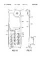
- FIG. 1is pictorial perspective view of a disposable wireless telephone constructed in accordance with one aspect of the present invention
- FIG. 2is a front elevational view of the disposable wireless telephone
- FIG. 3is a side elevational view of the disposable wireless telephone
- FIG. 4is a cross-sectional view taken along line 4--4 of FIG. 2;
- FIG. 5is a fragment of a cross-sectional view similar to FIG. 4, but showing an alternate arrangement
- FIG. 6is a schematic diagram showing a portion of the operating circuitry of the disposable wireless telephone
- FIG. 7is a schematic diagram showing an alternate embodiment
- FIG. 8is a schematic diagram showing another alternate embodiment
- FIG. 9is a schematic diagram showing a further alternate embodiment
- FIG. 10is a front elevational view of another disposable wireless telephone constructed in accordance with the present invention.
- FIG. 11is a side elevational view of the disposable wireless telephone of FIG. 10;
- FIG. 12is a top plan view of the telephone of FIG. 10;
- FIG. 13is a rear elevational view of the telephone of FIG. 10;
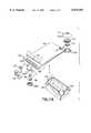
- FIG. 14is an exploded perspective, partially diagrammatic, view of a component of the telephone of FIG. 10;
- FIG. 15is a perspective, partially diagrammatic, view of the component of FIG. 14.
- FIG. 16is an exploded perspective, partially diagrammatic, view of the telephone of FIG. 10.
- a disposable wireless telephoneis illustrated generally at 10 and is seen to include a case 12 having a front case member 14 and a rear case member 16, joined together along abutting edges 18.
- An earphone grille portion 20is located adjacent an upper end 22 of the case 12, and a microphone grille portion 24 is located adjacent a lower end 26 of the case 12.
- a call destination selectorin the form of a keypad 30, and an antenna 32 extends upwardly from the upper end 22.
- the case 12includes a case wall 34 which provides the telephone 10 with an overall outer configuration 36 designed for aesthetic as well as for functional purposes.
- a circuit board 40is located within the case 12 and is connected to an earphone 42 placed behind the earphone grille portion 20, a microphone 44 placed behind the microphone grille portion 24, the keypad 30 and the antenna 32.
- the electronic components of the telephone 10are carried by the circuit board 40 and a power source in the form of a power battery 46, connected to the circuit board 40 through a power switch 48 (see FIGS. 1 and 2), provides the power necessary to operate the telephone 10.
- the case wall 34is relatively thin and is constructed of a relatively inexpensive synthetic polymeric material, such as by vacuum forming the front case member 14 and the rear case member 16 from thin sheets of ABS or styrene, the sheets typically having a thickness of about 0.060 inch.
- the illustrated componentsthen are located within the case 12 and the case 12 is closed permanently, as by welding or by adhesive bonding along the abutting edges 18 of the case members 14 and 16.
- a matrix 49is placed in the case 12 so that the components located within the case 12 are embedded within the matrix 49 and cannot be accessed without destruction of the working arrangement of component parts.
- the matrix 49serves as a filler which mechanically reinforces the relatively thin wall 34 of the case 12.
- the matrix 49preferably is constructed of a synthetic polymeric material, such as an epoxy resin, or a mastic-like material currently available for such use. In this manner, tampering is deterred. In total, the described construction is relatively inexpensive and therefore readily expendable.
- the power sourceincludes an external power battery 46A, rather than the internal power battery 46, the external power battery 46A being received within a receptacle 46B in the case 12 and connected to circuit board 40, through power switch 48, by means of an electrical connector 46C.
- power battery 46Amay be recovered for further use, while telephone 10 is discarded, or an exhausted power battery 46A may be disposed of separately, in compliance with environmental considerations.
- Telephone 10is rendered disposable by virtue of being capable of use only for the duration of a limited period, after which period telephone 10 is inoperative and is discarded. To that end, telephone 10 includes component parts which enable only limited use and ready disposal. Referring now to FIG. 6, as well as to FIG. 4, the circuitry incorporated into telephone 10, and located primarily on circuit board 40, is shown in schematic fashion and is seen to include telephonic means in the form of conventional wireless telephone circuitry 50 for receiving and transmitting wireless telephonic communications.
- Enabling/disabling meansare incorporated for enabling telephonic communication for only a predetermined limited period, and disabling telephonic communication upon expiration of the predetermined limited period, whereby telephone 10 is rendered inoperative and is capable of being discarded at the end of the predetermined limited period.
- telephone 10includes selective operating means for operating the telephonic means for telephonic communications of selected durations.
- the selective operating meansis shown in the form of a send/receive switch 52 selectively operated by the user of the telephone 10 to send a telephonic communication when a telephone call is to be made, and to terminate the telephonic communication when the call is complete.
- switch 52is actuated manually between an "on” mode and an “off” mode to effect a telephonic communication having a duration corresponding to the time during which switch 52 is in the "on” mode.
- the power switch 48With the power switch 48 turned on, power from the power battery 46 is supplied, through a voltage regulator 54, to the wireless telephonic circuitry 50, as follows.
- p Setting meansis utilized for determining the duration of the predetermined limited period over which the telephone 10 will be operative.
- the setting meansincludes a setting battery 56 of selected, known capacity. With the power switch 48 in the "on” position and switch 52 in the "on” mode, setting battery 56 is connected to the collector of a transistor 58, and the transistor 58 is biased by the power battery 46.
- resistors 60, 62, 64 and 66will determine the rate of flow of current from the setting battery 56, and thus will provide a measured duration based upon the life of the setting battery 56. For example, where the setting battery 56 has a capacity of 30 mAH and the values of resistors 60, 62, 64 and 66 are chosen to draw 30 mA when switch 52 is in the "on" mode, the measured duration provided by the life of the setting battery 56 will be one hour.
- An integrated circuit 70provides an AND gate 72 interposed between the voltage regulator 54 and the telephone circuitry 50 and connected to the collector of the transistor 58 such that at the end of the measured duration provided by the life of the setting battery 56, power to the telephone circuitry will be discontinued by the AND gate 72, which serves as a disabling means, so that the telephone circuitry 50 will be disabled and telephone 10 will become inoperative. Accordingly, each time the switch 52 is placed in the "on" mode to make a telephone call, current will flow from the setting battery 56 at the selected rate. When the switch 52 is placed in the "off" mode at the end of the telephone call, the duration of the telephone call will have drained a given amount of the capacity of setting battery 56. When the sum of the durations of the telephone calls reaches the measured duration provided by the life of the setting battery 56, the telephone circuitry 50 is disabled and the telephone 10 becomes inoperative and is discarded.
- the setting meansincludes a timing mechanism 80 powered continuously by a power supply 82 and connected to an oscillator 84, which also is powered by the power supply 82 and supplies the timing mechanism 80 with a timing signal.
- Selector meansshown in the form of manually operated thumb wheels 86, enable the input of a prescribed time into the timing mechanism 80, through input terminals 88.
- Output terminals 90 of the timing mechanism 80are connected to the telephone circuitry 50 through an OR gate 92.
- a start/stop indicator 94is responsive to the send/receive switch 52 such that upon the initiation of a telephone call, a start signal is provided to the timing mechanism 80 and upon completion of the telephone call, a stop signal is provided to the timing mechanism 80, enabling the timing mechanism 80, in concert with the oscillator 84, to count toward the prescribed time set into the timing mechanism 80 by the thumb wheels 86, for the duration of each telephone call, and thus compare the sum of the selected durations to the prescribed time set into the timing mechanism 80.
- the OR gate 92which serves as a disabling means, discontinues power to the telephone circuitry 50, so that the telephone circuitry 50 will be disabled and telephone 10 will become inoperative.
- the setting meansis embedded within the matrix 49, along with the remainder of the internal components of the telephone 10, as described above, so as to deter tampering which could alter the duration of the predetermined limited period.
- the alternate arrangement illustrated in FIG. 8enables telephone 10 to be utilized for telephone communications which are directed to different rate destinations. Since telephone rates ordinarily differ in accordance with the destination of a telephone call, such as local calls, out-of-area calls, long-distance calls and international calls, the alternate of FIG. 8 accommodates such differences.
- a rate code means shown in the form of a rate code analyzer 100is placed in the arrangement so as to be responsive to the keypad 30 of the telephone circuitry 50 for operating the oscillator 84 and, hence, the timing mechanism 80, at a rate determined by the destination of the telephone call selected at the keypad 30.
- the selector meansagain shown in the form of thumb wheels 86, enable the input of a selected maximum time into the timing mechanism 80, through the input terminals 88.
- the timing mechanism 80in concert with the oscillator 84, counts toward the prescribed time set into the timing mechanism 80 by the thumb wheels 86, for the duration of each telephone call.
- each telephone callis weighted with a rate factor, by the rate code analyzer 100; that is, the rate code analyzer 100 is responsive to the keypad 30 for operating the timing mechanism 80, through varying the rate of operation of the oscillator 84, at a rate determined by the destination of the telephone call selected at the keypad 30.
- the duration of the limited period during which the timing mechanism 80 permits telephonic communicationsis varied in accordance with the call rate applied to each telephone call.
- telephone 10is activated and charged at a point of purchase with preset call rates for a predetermined use cycle and, upon reaching the end of the use cycle, the telephone 10 is rendered inoperative and is discarded.
- telephone 10is capable of being used for telephone calls in a local area at a first call rate, for out-of-area calls at a second call rate which is twice the first call rate, for long-distance calls at a third call rate which is three times the first call rate, and for international calls at a fourth call rate which is four times the first call rate
- telephone 10is charged initially with a use time of one hour of local telephone calls, as by setting the timing mechanism 80 for a maximum limited period of one hour.
- the rate code analyzer 100determines which of the four call rates is applicable to the selected telephone call destination and operates the oscillator 84 at a corresponding rate so that the timing mechanism 80 will count at a faster or slower rate, depending upon the applicable call rate. Thus, if all telephone calls are within the local calling area, the calls will be weighted with the first call rate and the telephone 10 will remain in operation for a total of one hour of telephone call time. If the telephone calls are all international telephone calls, the calls will be weighted with the fourth call rate and the telephone 10 will remain in operation for a total of fifteen minutes. Telephone calls placed in the various four areas will result in the application of corresponding call rates so that the duration of the limited period during which the telephone 10 can remain in operation is varied in accordance with the accumulated telephone call time, as weighted by the different call rates.
- FIG. 8includes a use-time indicator 102 having both an audio indicator 104, which applies an audible indication in the form of a muted buzzing sound to the earphone 42, and a visual indicator 106, which furnishes a visible indication, both the audible and visible indications advising that only a limited amount of use time, for example, five minutes, remains available.
- rate code analyzer 100is placed in an arrangement similar to the arrangement described in connection with FIG. 6, so as to be responsive to the keypad 30 of the telephone circuitry 50 for operating the variable resistor 66 to draw current from the setting battery 56 at a rate determined by the destination of the telephone call selected at the keypad 30.
- the duration of the limited period provided by the life of the setting battery 56is varied in accordance with the call rate applied to each telephone call, in a manner analogous to that described in connection with the arrangement of FIG. 8.
- the alternate arrangement of FIG. 9includes a use-time indicator 102 having an audio indicator 104 and a visual indicator 106.
- a call signal transmitted from a telephone constructed in accordance with the inventionpreferably includes an intermittent encrypted code so that a connection is maintained throughout the course of a telephonic communication. Any unencrypted signal is dropped out within a very short time to prevent unauthorized use of the carrier signal service. In this manner the telephone and the use time is prepaid at the time of purchase of the telephone and there in no necessity for any complex real time use billing system.
- FIGS. 10 through 16another disposable wireless telephone is illustrated generally at 110 and is seen to have an integrated body 112 extending longitudinally between a top end 114 and an opposite bottom end 116 and laterally between opposite sides 118.
- An earphone assembly 120is connected to the body 112 at the top end 114, preferably offset toward one side 118 of the body 112, and a microphone assembly 122 is connected to the body 112 at the bottom end 116.
- a keypad 130is placed beneath the front face 132 of the body 112, adjacent the bottom end 116, and an antenna 134 is embedded within the body 112 and extends longitudinally adjacent one of the sides 118.
- a power battery 140is housed within a battery housing 142 attached to the body 112 at the rear face 144 of the body 112, all in a manner set forth more specifically below.
- a power switch 146controls power from the power battery 140, and a send/receive switch is shown at 148.
- the body 112is relatively thin between the front face 132 and the rear face 144 and preferably includes a magnetic strip 149 along the rear face 144 for enabling activation of the telephone 110.
- the construction of body 112, as set forth in detail hereinafter,provides the body 112 with a mechanical stiffness which enables the telephone 110 to be hand held during use in telephonic communication.
- body 112 of telephone 110includes a core 150 comprised of a circuit board 152 which carries the circuitry and the electronic components of the telephone 110.
- circuit board 152is constructed of a plurality of layers 154 which are laminated together to establish the circuit board 152.
- Each layer 154carries circuitry and components and the circuitry among the layers 154 is connected upon joining the layers 154 in the single laminated structure illustrated as circuit board 152, as by connectors 156 on the layers 154.
- Sheath 160preferably is constructed of a thin, compliant material which closely covers, and preferably is laminated to, the core 150, and which accepts printing or another means for displaying indicia on the faces 132 and 144 of the body 112.
- a preferred material for sheath 160is a synthetic polymeric material such as polyvinylchloride.
- the earphone assembly 120protrudes beyond the sheath 160 and includes an earphone 170 placed within an earphone housing 172, between upper and lower housing members 172A and 172B, and connected to a clip connector 174 which, in turn, is clipped to the circuit board 152 at 176 to be mounted mechanically on the core 150 and connected electrically to the circuit board 152.
- the microphone assembly 122protrudes beyond the sheath 160 and includes a microphone 180 placed within a microphone housing 182, between upper and lower housing members 182A and 182B, and connected to a clip connector 184 which, in turn, is clipped to the circuit board 152 at 186 to be mounted mechanically on the core 150 and connected electrically to the circuit board 152.
- a battery connector 190protrudes beyond the sheath 160 and is connected to a clip connector 192 which, in turn, is clipped to the circuit board 152 at 194.
- Battery connector 190is connected to power battery 140 and battery housing 142 is mounted upon body 112 by means of clips 196 which are integral with battery housing 142.
- keypad 130lies beneath the sheath 160 and keypad indicia 200 is printed upon the sheath 160, on the front face 132 of the body 112, the resilient nature of the sheath 160 enabling the keypad 130 to be actuated by depressing the sheath 160 at the appropriate locations, as indicated by the printed indicia 200.
- Additional graphic areas 202 and 204are provided on the front face 132 and on the rear face 144 for optionally displaying advertising and promotional graphics.
- Telephone 110is very lightweight, compact and rugged, as well as resistant to damage from water and the elements. Further, the laminated construction of core 150, and the circuit board 152 thereof, deters tampering with the electronic components of the telephone 110. The construction is aesthetically pleasing and enables relatively economical manufacture, rendering telephone 110 expendable and readily disposable.
- FIGS. 6, 7, 8 and 9provides a simple and economical arrangement for enabling telephones 10 and 110 to be constructed at minimal cost for use for only a limited period, after which period the telephone 10 or 110 is inoperative and may be discarded. These alternatives are provided by way of example, other alternative arrangements being available for assuring that the telephone 10 or 110 is rendered operative only for a limited time.
- telephones constructed in accordance with the present inventionmay be purchased at a relatively low price and made available at a very wide variety of sales outlets. In this manner, wireless telephones and wireless telephone services are made available to a much wider population for convenience as well as for emergency uses, with economy.
- the present inventionattains the several objects and advantages summarized above; namely: Simplifies and renders more economical the use of wireless telephone services; renders wireless telephone services available to a larger audience at lowered cost; facilitates the distribution and use of wireless telephones; reduces the expense of wireless telephones and wireless telephone services; promotes the use of wireless telephones and wireless telephone services by those who otherwise would not invest in a wireless telephone and expend funds for wireless telephone services; facilitates the availability of wireless telephones and wireless telephone services for emergency uses; provides added convenience in obtaining as well as using wireless telephones and wireless telephone services.
Landscapes
- Engineering & Computer Science (AREA)
- Signal Processing (AREA)
- Computer Networks & Wireless Communication (AREA)
- Computer Security & Cryptography (AREA)
- Health & Medical Sciences (AREA)
- Public Health (AREA)
- Mobile Radio Communication Systems (AREA)
Abstract
Description
Claims (10)
Priority Applications (7)
| Application Number | Priority Date | Filing Date | Title |
|---|---|---|---|
| US08/844,149US5875393A (en) | 1997-02-28 | 1997-04-18 | Disposable wireless telephone and method |
| US08/958,119US6061580A (en) | 1997-02-28 | 1997-10-27 | Disposable wireless telephone and method for call-out only |
| CA002317394ACA2317394A1 (en) | 1997-02-28 | 1998-02-24 | Disposable wireless telephone and method |
| AU63370/98AAU6337098A (en) | 1997-02-28 | 1998-02-24 | Disposable wireless telephone and method |
| EP98907607AEP1005749A4 (en) | 1997-02-28 | 1998-02-24 | Disposable wireless telephone and method |
| PCT/US1998/003583WO1998038810A2 (en) | 1997-02-28 | 1998-02-24 | Disposable wireless telephone and method |
| US09/222,136US6405031B1 (en) | 1997-02-28 | 1998-12-29 | Wireless telephone system, telephone and method |
Applications Claiming Priority (2)
| Application Number | Priority Date | Filing Date | Title |
|---|---|---|---|
| US08/808,339US5845218A (en) | 1997-02-28 | 1997-02-28 | Disposable wireless telephone and method |
| US08/844,149US5875393A (en) | 1997-02-28 | 1997-04-18 | Disposable wireless telephone and method |
Related Parent Applications (1)
| Application Number | Title | Priority Date | Filing Date |
|---|---|---|---|
| US08/808,339Continuation-In-PartUS5845218A (en) | 1997-02-28 | 1997-02-28 | Disposable wireless telephone and method |
Related Child Applications (2)
| Application Number | Title | Priority Date | Filing Date |
|---|---|---|---|
| US08/958,119Continuation-In-PartUS6061580A (en) | 1997-02-28 | 1997-10-27 | Disposable wireless telephone and method for call-out only |
| US09/222,136Continuation-In-PartUS6405031B1 (en) | 1997-02-28 | 1998-12-29 | Wireless telephone system, telephone and method |
Publications (1)
| Publication Number | Publication Date |
|---|---|
| US5875393Atrue US5875393A (en) | 1999-02-23 |
Family
ID=27123112
Family Applications (1)
| Application Number | Title | Priority Date | Filing Date |
|---|---|---|---|
| US08/844,149Expired - Fee RelatedUS5875393A (en) | 1997-02-28 | 1997-04-18 | Disposable wireless telephone and method |
Country Status (1)
| Country | Link |
|---|---|
| US (1) | US5875393A (en) |
Cited By (49)
| Publication number | Priority date | Publication date | Assignee | Title |
|---|---|---|---|---|
| US6061580A (en)* | 1997-02-28 | 2000-05-09 | Randice-Lisa Altschul | Disposable wireless telephone and method for call-out only |
| US6112077A (en)* | 1995-12-29 | 2000-08-29 | Stx Corporation | Nonreusable cellular telephone |
| US20020022489A1 (en)* | 2000-03-30 | 2002-02-21 | Masahiro Odashima | Wireless terminal for mobile unit |
| US6351629B1 (en) | 2000-09-12 | 2002-02-26 | Dieceland Technologies Corp. | Compact modular wireless telephone |
| USD455139S1 (en) | 2001-08-10 | 2002-04-02 | Shirley A Roberts | Disposable pre-paid mobile phone |
| US6405056B1 (en) | 2000-09-12 | 2002-06-11 | Dieceland Technologies Corp. | Compact wireless telephone with enabling module |
| US20020137555A1 (en)* | 2001-03-23 | 2002-09-26 | Sonya Posey | Disposable wireless communication system |
| US6485461B1 (en) | 2000-04-04 | 2002-11-26 | Insulet, Inc. | Disposable infusion device |
| US20020193092A1 (en)* | 2001-06-14 | 2002-12-19 | International Business Machines Corporation | Tracking communications usage time |
| US20030003954A1 (en)* | 2001-06-29 | 2003-01-02 | Kugler Brett E. | Business card with integrated paper cell phone |
| US6656159B2 (en) | 2002-04-23 | 2003-12-02 | Insulet Corporation | Dispenser for patient infusion device |
| US6656158B2 (en) | 2002-04-23 | 2003-12-02 | Insulet Corporation | Dispenser for patient infusion device |
| US6669669B2 (en) | 2001-10-12 | 2003-12-30 | Insulet Corporation | Laminated patient infusion device |
| US20040015131A1 (en)* | 2002-07-16 | 2004-01-22 | Flaherty J. Christopher | Flow restriction system and method for patient infusion device |
| US20040027083A1 (en)* | 2002-04-26 | 2004-02-12 | Toyoda Koki Kabushiki Kaisha | Motor control device |
| US6692457B2 (en) | 2002-03-01 | 2004-02-17 | Insulet Corporation | Flow condition sensor assembly for patient infusion device |
| US6699218B2 (en) | 2000-11-09 | 2004-03-02 | Insulet Corporation | Transcutaneous delivery means |
| US20040064096A1 (en)* | 2002-09-30 | 2004-04-01 | Flaherty J. Christopher | Components and methods for patient infusion device |
| US20040064088A1 (en)* | 2002-09-30 | 2004-04-01 | William Gorman | Dispenser components and methods for patient infusion device |
| US6723072B2 (en) | 2002-06-06 | 2004-04-20 | Insulet Corporation | Plunger assembly for patient infusion device |
| US20040077388A1 (en)* | 2002-10-16 | 2004-04-22 | Ward-Kraft, Inc. | Compact electronic communication device with self-mounting feature and method of removably coupling such a device to a surface |
| US20040078028A1 (en)* | 2001-11-09 | 2004-04-22 | Flaherty J. Christopher | Plunger assembly for patient infusion device |
| US20040087894A1 (en)* | 2000-09-08 | 2004-05-06 | Flaherty J. Christopher | Devices, systems and methods for patient infusion |
| US6749587B2 (en) | 2001-02-22 | 2004-06-15 | Insulet Corporation | Modular infusion device and method |
| US20040116866A1 (en)* | 2002-12-17 | 2004-06-17 | William Gorman | Skin attachment apparatus and method for patient infusion device |
| US6768425B2 (en) | 2000-12-21 | 2004-07-27 | Insulet Corporation | Medical apparatus remote control and method |
| US20040153032A1 (en)* | 2002-04-23 | 2004-08-05 | Garribotto John T. | Dispenser for patient infusion device |
| US6813497B2 (en) | 2000-10-20 | 2004-11-02 | Leap Wirelesss International | Method for providing wireless communication services and network and system for delivering same |
| EP1480419A1 (en)* | 2003-05-23 | 2004-11-24 | Nokia Corporation | Systems and methods for recycling of cell phones at end of life |
| US6830558B2 (en) | 2002-03-01 | 2004-12-14 | Insulet Corporation | Flow condition sensor assembly for patient infusion device |
| US20050065760A1 (en)* | 2003-09-23 | 2005-03-24 | Robert Murtfeldt | Method for advising patients concerning doses of insulin |
| US20050070847A1 (en)* | 2003-09-29 | 2005-03-31 | Van Erp Wilhelmus Petrus Martinus Maria | Rapid-exchange balloon catheter with hypotube shaft |
| US20050182366A1 (en)* | 2003-04-18 | 2005-08-18 | Insulet Corporation | Method For Visual Output Verification |
| US20050238507A1 (en)* | 2002-04-23 | 2005-10-27 | Insulet Corporation | Fluid delivery device |
| US20050237184A1 (en)* | 2000-01-24 | 2005-10-27 | Scott Muirhead | RF-enabled pallet |
| US6960192B1 (en) | 2002-04-23 | 2005-11-01 | Insulet Corporation | Transcutaneous fluid delivery system |
| US6970692B2 (en) | 2001-04-12 | 2005-11-29 | International Business Machines Corporation | Cell phone minute usage calculation and display |
| US20060178633A1 (en)* | 2005-02-03 | 2006-08-10 | Insulet Corporation | Chassis for fluid delivery device |
| US20060288125A1 (en)* | 2005-05-23 | 2006-12-21 | Boyd William T | System and method for user space operations for direct I/O between an application instance and an I/O adapter |
| US20070178937A1 (en)* | 2004-03-10 | 2007-08-02 | Koninklijke Philips Electronics N.V. | Mobile terminal with reduced components |
| US20080122610A1 (en)* | 2000-01-24 | 2008-05-29 | Nextreme L.L.C. | RF-enabled pallet |
| US20140087787A1 (en)* | 2011-05-20 | 2014-03-27 | Antonio Rivera-Sanchez | Business card with incorporated ringer |
| US10716896B2 (en) | 2015-11-24 | 2020-07-21 | Insulet Corporation | Wearable automated medication delivery system |
| US10898656B2 (en) | 2017-09-26 | 2021-01-26 | Insulet Corporation | Needle mechanism module for drug delivery device |
| US11045603B2 (en) | 2017-02-22 | 2021-06-29 | Insulet Corporation | Needle insertion mechanisms for drug containers |
| US11147931B2 (en) | 2017-11-17 | 2021-10-19 | Insulet Corporation | Drug delivery device with air and backflow elimination |
| US11364341B2 (en) | 2015-11-25 | 2022-06-21 | Insulet Corporation | Wearable medication delivery device |
| US11684713B2 (en) | 2012-03-30 | 2023-06-27 | Insulet Corporation | Fluid delivery device, transcutaneous access tool and insertion mechanism for use therewith |
| US12433512B2 (en) | 2020-12-18 | 2025-10-07 | Insulet Corporation | Adhesive pad with a metallic coil for securing an on-body medical device |
Citations (10)
| Publication number | Priority date | Publication date | Assignee | Title |
|---|---|---|---|---|
| US4783799A (en)* | 1984-09-17 | 1988-11-08 | Maass Joachim A | Electronic communications and control system |
| US5161250A (en)* | 1990-04-12 | 1992-11-03 | Play Action Inc. | Single use radio device and method for using the same |
| GB2262685A (en)* | 1991-12-19 | 1993-06-23 | Brian Crossley | Disposable portable telephone |
| US5365570A (en)* | 1992-06-02 | 1994-11-15 | Boubelik Mark J | Emergency cellular telephone apparatus |
| US5423080A (en)* | 1991-03-12 | 1995-06-06 | Thomson Trt Defense | Microwave transceiver using the technique of multilayer printed circuits |
| US5461664A (en)* | 1993-04-07 | 1995-10-24 | Cappadona; Steven | Emergency wireless telephone |
| WO1996003001A1 (en)* | 1994-07-20 | 1996-02-01 | Sima Cohn | Cellular phone of the disposable type |
| US5504808A (en)* | 1994-06-01 | 1996-04-02 | Hamrick, Jr.; James N. | Secured disposable debit card calling system and method |
| US5577100A (en)* | 1995-01-30 | 1996-11-19 | Telemac Cellular Corporation | Mobile phone with internal accounting |
| US5631947A (en)* | 1991-03-04 | 1997-05-20 | Megatrend Telecommunications, Inc. | Mobile telephone device for storing a plurality of changable charge rates and time limit data |
- 1997
- 1997-04-18USUS08/844,149patent/US5875393A/ennot_activeExpired - Fee Related
Patent Citations (10)
| Publication number | Priority date | Publication date | Assignee | Title |
|---|---|---|---|---|
| US4783799A (en)* | 1984-09-17 | 1988-11-08 | Maass Joachim A | Electronic communications and control system |
| US5161250A (en)* | 1990-04-12 | 1992-11-03 | Play Action Inc. | Single use radio device and method for using the same |
| US5631947A (en)* | 1991-03-04 | 1997-05-20 | Megatrend Telecommunications, Inc. | Mobile telephone device for storing a plurality of changable charge rates and time limit data |
| US5423080A (en)* | 1991-03-12 | 1995-06-06 | Thomson Trt Defense | Microwave transceiver using the technique of multilayer printed circuits |
| GB2262685A (en)* | 1991-12-19 | 1993-06-23 | Brian Crossley | Disposable portable telephone |
| US5365570A (en)* | 1992-06-02 | 1994-11-15 | Boubelik Mark J | Emergency cellular telephone apparatus |
| US5461664A (en)* | 1993-04-07 | 1995-10-24 | Cappadona; Steven | Emergency wireless telephone |
| US5504808A (en)* | 1994-06-01 | 1996-04-02 | Hamrick, Jr.; James N. | Secured disposable debit card calling system and method |
| WO1996003001A1 (en)* | 1994-07-20 | 1996-02-01 | Sima Cohn | Cellular phone of the disposable type |
| US5577100A (en)* | 1995-01-30 | 1996-11-19 | Telemac Cellular Corporation | Mobile phone with internal accounting |
Cited By (83)
| Publication number | Priority date | Publication date | Assignee | Title |
|---|---|---|---|---|
| US6112077A (en)* | 1995-12-29 | 2000-08-29 | Stx Corporation | Nonreusable cellular telephone |
| US6332074B1 (en) | 1995-12-29 | 2001-12-18 | Stx Corp | Nonreusable cellular telephone and method of making cellular telephone calls |
| US6876848B2 (en) | 1995-12-29 | 2005-04-05 | Stx Corporation | Nonreusable cellular telephone |
| US6061580A (en)* | 1997-02-28 | 2000-05-09 | Randice-Lisa Altschul | Disposable wireless telephone and method for call-out only |
| US20080122610A1 (en)* | 2000-01-24 | 2008-05-29 | Nextreme L.L.C. | RF-enabled pallet |
| US8077040B2 (en) | 2000-01-24 | 2011-12-13 | Nextreme, Llc | RF-enabled pallet |
| US20070171080A1 (en)* | 2000-01-24 | 2007-07-26 | Scott Muirhead | Material handling apparatus with a cellular communications device |
| US7342496B2 (en) | 2000-01-24 | 2008-03-11 | Nextreme Llc | RF-enabled pallet |
| US20050237184A1 (en)* | 2000-01-24 | 2005-10-27 | Scott Muirhead | RF-enabled pallet |
| US7948371B2 (en) | 2000-01-24 | 2011-05-24 | Nextreme Llc | Material handling apparatus with a cellular communications device |
| US9230227B2 (en) | 2000-01-24 | 2016-01-05 | Nextreme, Llc | Pallet |
| US20020022489A1 (en)* | 2000-03-30 | 2002-02-21 | Masahiro Odashima | Wireless terminal for mobile unit |
| US7016656B2 (en)* | 2000-03-30 | 2006-03-21 | Pioneer Corporation | Wireless terminal for mobile unit |
| US6485461B1 (en) | 2000-04-04 | 2002-11-26 | Insulet, Inc. | Disposable infusion device |
| US20050171512A1 (en)* | 2000-09-08 | 2005-08-04 | Insulet Corporation | Devices, systems and methods for patient infusion |
| US20040087894A1 (en)* | 2000-09-08 | 2004-05-06 | Flaherty J. Christopher | Devices, systems and methods for patient infusion |
| US7137964B2 (en) | 2000-09-08 | 2006-11-21 | Insulet Corporation | Devices, systems and methods for patient infusion |
| US7029455B2 (en) | 2000-09-08 | 2006-04-18 | Insulet Corporation | Devices, systems and methods for patient infusion |
| US6405056B1 (en) | 2000-09-12 | 2002-06-11 | Dieceland Technologies Corp. | Compact wireless telephone with enabling module |
| WO2002023928A1 (en)* | 2000-09-12 | 2002-03-21 | Dieceland Technologies Corp. | Compact modular wireless telephone |
| US6351629B1 (en) | 2000-09-12 | 2002-02-26 | Dieceland Technologies Corp. | Compact modular wireless telephone |
| US6813497B2 (en) | 2000-10-20 | 2004-11-02 | Leap Wirelesss International | Method for providing wireless communication services and network and system for delivering same |
| US7684804B2 (en) | 2000-10-20 | 2010-03-23 | Cricket Communications, Inc. | Method for providing wireless communication services and network and system for delivering same |
| US20080200176A1 (en)* | 2000-10-20 | 2008-08-21 | Doug Hutcheson | Method for providing wireless communication services and network and system for delivering same |
| US6699218B2 (en) | 2000-11-09 | 2004-03-02 | Insulet Corporation | Transcutaneous delivery means |
| WO2002051175A1 (en)* | 2000-12-20 | 2002-06-27 | Dieceland Technologies Corp. | Compact wireless telephone with enabling module |
| US6768425B2 (en) | 2000-12-21 | 2004-07-27 | Insulet Corporation | Medical apparatus remote control and method |
| US6749587B2 (en) | 2001-02-22 | 2004-06-15 | Insulet Corporation | Modular infusion device and method |
| US6816738B2 (en)* | 2001-03-23 | 2004-11-09 | Sonya Posey | Disposable wireless communication system |
| US20020137555A1 (en)* | 2001-03-23 | 2002-09-26 | Sonya Posey | Disposable wireless communication system |
| US6970692B2 (en) | 2001-04-12 | 2005-11-29 | International Business Machines Corporation | Cell phone minute usage calculation and display |
| US20020193092A1 (en)* | 2001-06-14 | 2002-12-19 | International Business Machines Corporation | Tracking communications usage time |
| US7711350B2 (en)* | 2001-06-14 | 2010-05-04 | International Business Machines Corporation | Tracking communications usage time |
| US7058365B2 (en)* | 2001-06-29 | 2006-06-06 | Hewlett-Packard Development Company, L.P. | Business card with integrated paper cell phone |
| US20030003954A1 (en)* | 2001-06-29 | 2003-01-02 | Kugler Brett E. | Business card with integrated paper cell phone |
| USD455139S1 (en) | 2001-08-10 | 2002-04-02 | Shirley A Roberts | Disposable pre-paid mobile phone |
| US20050021005A1 (en)* | 2001-10-12 | 2005-01-27 | Flaherty J. Christopher | Laminated patient infusion device |
| US6669669B2 (en) | 2001-10-12 | 2003-12-30 | Insulet Corporation | Laminated patient infusion device |
| US20040078028A1 (en)* | 2001-11-09 | 2004-04-22 | Flaherty J. Christopher | Plunger assembly for patient infusion device |
| US20040092865A1 (en)* | 2001-11-09 | 2004-05-13 | J. Christopher Flaherty | Transcutaneous delivery means |
| US7887505B2 (en) | 2002-03-01 | 2011-02-15 | Insulet Corporation | Flow condition sensor assembly for patient infusion device |
| US6830558B2 (en) | 2002-03-01 | 2004-12-14 | Insulet Corporation | Flow condition sensor assembly for patient infusion device |
| US20040127844A1 (en)* | 2002-03-01 | 2004-07-01 | Flaherty J. Christopher | Flow condition sensor assembly for patient infusion device |
| US6692457B2 (en) | 2002-03-01 | 2004-02-17 | Insulet Corporation | Flow condition sensor assembly for patient infusion device |
| US7303549B2 (en) | 2002-04-23 | 2007-12-04 | Insulet Corporation | Transcutaneous fluid delivery system |
| US20040153032A1 (en)* | 2002-04-23 | 2004-08-05 | Garribotto John T. | Dispenser for patient infusion device |
| US20050238507A1 (en)* | 2002-04-23 | 2005-10-27 | Insulet Corporation | Fluid delivery device |
| US6656159B2 (en) | 2002-04-23 | 2003-12-02 | Insulet Corporation | Dispenser for patient infusion device |
| US6656158B2 (en) | 2002-04-23 | 2003-12-02 | Insulet Corporation | Dispenser for patient infusion device |
| US6960192B1 (en) | 2002-04-23 | 2005-11-01 | Insulet Corporation | Transcutaneous fluid delivery system |
| US20040027083A1 (en)* | 2002-04-26 | 2004-02-12 | Toyoda Koki Kabushiki Kaisha | Motor control device |
| US6723072B2 (en) | 2002-06-06 | 2004-04-20 | Insulet Corporation | Plunger assembly for patient infusion device |
| US7018360B2 (en) | 2002-07-16 | 2006-03-28 | Insulet Corporation | Flow restriction system and method for patient infusion device |
| US20060041229A1 (en)* | 2002-07-16 | 2006-02-23 | Insulet Corporation | Flow restriction system and method for patient infusion device |
| US20040015131A1 (en)* | 2002-07-16 | 2004-01-22 | Flaherty J. Christopher | Flow restriction system and method for patient infusion device |
| US7128727B2 (en) | 2002-09-30 | 2006-10-31 | Flaherty J Christopher | Components and methods for patient infusion device |
| US20040064096A1 (en)* | 2002-09-30 | 2004-04-01 | Flaherty J. Christopher | Components and methods for patient infusion device |
| US7144384B2 (en) | 2002-09-30 | 2006-12-05 | Insulet Corporation | Dispenser components and methods for patient infusion device |
| US20040064088A1 (en)* | 2002-09-30 | 2004-04-01 | William Gorman | Dispenser components and methods for patient infusion device |
| US6947777B2 (en) | 2002-10-16 | 2005-09-20 | Ward-Kraft, Inc. | Compact electronic communication device with self-mounting feature and method of removably coupling such a device to a surface |
| US20040077388A1 (en)* | 2002-10-16 | 2004-04-22 | Ward-Kraft, Inc. | Compact electronic communication device with self-mounting feature and method of removably coupling such a device to a surface |
| US20040116866A1 (en)* | 2002-12-17 | 2004-06-17 | William Gorman | Skin attachment apparatus and method for patient infusion device |
| US20050182366A1 (en)* | 2003-04-18 | 2005-08-18 | Insulet Corporation | Method For Visual Output Verification |
| US7251458B2 (en)* | 2003-05-23 | 2007-07-31 | Nokia Corporation | Systems and methods for recycling of cell phones at the end of life |
| EP1480419A1 (en)* | 2003-05-23 | 2004-11-24 | Nokia Corporation | Systems and methods for recycling of cell phones at end of life |
| US20050065760A1 (en)* | 2003-09-23 | 2005-03-24 | Robert Murtfeldt | Method for advising patients concerning doses of insulin |
| US20050070847A1 (en)* | 2003-09-29 | 2005-03-31 | Van Erp Wilhelmus Petrus Martinus Maria | Rapid-exchange balloon catheter with hypotube shaft |
| US20070178937A1 (en)* | 2004-03-10 | 2007-08-02 | Koninklijke Philips Electronics N.V. | Mobile terminal with reduced components |
| US7599713B2 (en)* | 2004-03-10 | 2009-10-06 | Nxp B.V. | Mobile terminal with reduced components |
| US20060178633A1 (en)* | 2005-02-03 | 2006-08-10 | Insulet Corporation | Chassis for fluid delivery device |
| US20060288125A1 (en)* | 2005-05-23 | 2006-12-21 | Boyd William T | System and method for user space operations for direct I/O between an application instance and an I/O adapter |
| US20140087787A1 (en)* | 2011-05-20 | 2014-03-27 | Antonio Rivera-Sanchez | Business card with incorporated ringer |
| US9154590B2 (en)* | 2011-05-20 | 2015-10-06 | Antonio Rivera-Sanchez | Business card with incorporated ringer |
| US12329928B2 (en) | 2012-03-30 | 2025-06-17 | Insulet Corporation | Fluid delivery device, transcutaneous access tool and fluid drive mechanism for use therewith |
| US11684713B2 (en) | 2012-03-30 | 2023-06-27 | Insulet Corporation | Fluid delivery device, transcutaneous access tool and insertion mechanism for use therewith |
| US11744944B2 (en) | 2015-11-24 | 2023-09-05 | Insulet Corporation | Wearable automated medication delivery system |
| US10716896B2 (en) | 2015-11-24 | 2020-07-21 | Insulet Corporation | Wearable automated medication delivery system |
| US11090434B2 (en) | 2015-11-24 | 2021-08-17 | Insulet Corporation | Automated drug delivery system |
| US11364341B2 (en) | 2015-11-25 | 2022-06-21 | Insulet Corporation | Wearable medication delivery device |
| US11045603B2 (en) | 2017-02-22 | 2021-06-29 | Insulet Corporation | Needle insertion mechanisms for drug containers |
| US10898656B2 (en) | 2017-09-26 | 2021-01-26 | Insulet Corporation | Needle mechanism module for drug delivery device |
| US11147931B2 (en) | 2017-11-17 | 2021-10-19 | Insulet Corporation | Drug delivery device with air and backflow elimination |
| US12433512B2 (en) | 2020-12-18 | 2025-10-07 | Insulet Corporation | Adhesive pad with a metallic coil for securing an on-body medical device |
Similar Documents
| Publication | Publication Date | Title |
|---|---|---|
| US5875393A (en) | Disposable wireless telephone and method | |
| US6061580A (en) | Disposable wireless telephone and method for call-out only | |
| US5845218A (en) | Disposable wireless telephone and method | |
| US5983094A (en) | Wireless telephone with credited airtime and method | |
| RU2159012C2 (en) | Communication device which has several indicators | |
| JP4149569B2 (en) | Closable communication device and method of operating the same | |
| EP1271899A1 (en) | Cover with induction coil for a mobile telephone handset | |
| CA2320976A1 (en) | Disposable portable electronic devices and method of making | |
| US6876848B2 (en) | Nonreusable cellular telephone | |
| EP1146490A3 (en) | Push-button switch member for a portable information terminal and payment system using the same | |
| WO2002003746A3 (en) | A microphone assembly | |
| EP0892533A3 (en) | Radio telephone | |
| GB2357930A (en) | Portable telephone having speaking state display means | |
| US20020098875A1 (en) | Portable telephone | |
| EP0193470A1 (en) | Telephone apparatus with a fixed post and mobile hand set | |
| US6405031B1 (en) | Wireless telephone system, telephone and method | |
| US6816738B2 (en) | Disposable wireless communication system | |
| KR100274298B1 (en) | Flip-typed portable telephone | |
| JP3036553U (en) | Mobile phone | |
| US20020155855A1 (en) | Conversation timer for mobile phone | |
| WO1991012593A1 (en) | Coded memory aid | |
| EP1171858A1 (en) | Distress call device | |
| KR200221184Y1 (en) | Telephon card that have a difference in time chart | |
| JP3865870B2 (en) | Radio signal transmitter for individual call receiver | |
| JP3091668B2 (en) | Mobile phone |
Legal Events
| Date | Code | Title | Description |
|---|---|---|---|
| AS | Assignment | Owner name:RANDICE-LISA ALTSCHUL, NEW JERSEY Free format text:ASSIGNMENT OF ASSIGNORS INTEREST;ASSIGNOR:VOLPE, LEE S.;REEL/FRAME:008584/0997 Effective date:19970507 | |
| AS | Assignment | Owner name:DIECELAND TECHNOLOGIES CORP., NEW JERSEY Free format text:ASSIGNMENT OF ASSIGNORS INTEREST;ASSIGNOR:ALTSCHUL, RANDICE-LISA;REEL/FRAME:010144/0498 Effective date:19990805 | |
| AS | Assignment | Owner name:DIECELAND TECHNOLOGIES, CORP., NEW JERSEY Free format text:RELEASE OF SECURITY INTEREST;ASSIGNOR:DIECELAND INVESTMENT 2000 LLC;REEL/FRAME:011987/0348 Effective date:20010710 | |
| AS | Assignment | Owner name:200 PARK LLC, NEW YORK Free format text:SECURITY AGREEMENT;ASSIGNOR:DIECELAND TECHNOLOGIES, CORP.;REEL/FRAME:012014/0347 Effective date:20010710 Owner name:WEISS, STEPHEN, NEW YORK Free format text:SECURITY AGREEMENT;ASSIGNOR:DIECELAND TECHNOLOGIES, CORP.;REEL/FRAME:012014/0347 Effective date:20010710 Owner name:LIMMER, ALLISON, NEW JERSEY Free format text:SECURITY AGREEMENT;ASSIGNOR:DIECELAND TECHNOLOGIES, CORP.;REEL/FRAME:012014/0347 Effective date:20010710 Owner name:HORMATS, ROBERT, NEW YORK Free format text:SECURITY AGREEMENT;ASSIGNOR:DIECELAND TECHNOLOGIES, CORP.;REEL/FRAME:012014/0347 Effective date:20010710 Owner name:KRISCH, SAMUEL J., III, VIRGINIA Free format text:SECURITY AGREEMENT;ASSIGNOR:DIECELAND TECHNOLOGIES, CORP.;REEL/FRAME:012014/0347 Effective date:20010710 Owner name:SNYDER, HAROLD, NEW YORK Free format text:SECURITY AGREEMENT;ASSIGNOR:DIECELAND TECHNOLOGIES, CORP.;REEL/FRAME:012014/0347 Effective date:20010710 Owner name:HBJ INVESTMENTS, LLC, NEW YORK Free format text:SECURITY AGREEMENT;ASSIGNOR:DIECELAND TECHNOLOGIES, CORP.;REEL/FRAME:012014/0347 Effective date:20010710 Owner name:CEPPES, KENNETH, NEW YORK Free format text:SECURITY AGREEMENT;ASSIGNOR:DIECELAND TECHNOLOGIES, CORP.;REEL/FRAME:012014/0347 Effective date:20010710 Owner name:CONESE, EUGENE P., SR., FLORIDA Free format text:SECURITY AGREEMENT;ASSIGNOR:DIECELAND TECHNOLOGIES, CORP.;REEL/FRAME:012014/0347 Effective date:20010710 | |
| AS | Assignment | Owner name:DRAPER, PAMELA P., VIRGINIA Free format text:SECURITY AGREEMENT;ASSIGNOR:DIECELAND TECHNOLOGIES, INC.;REEL/FRAME:012199/0134 Effective date:20010710 Owner name:DRAPER, S. RANDOLPH. JR., VIRGINIA Free format text:SECURITY AGREEMENT;ASSIGNOR:DIECELAND TECHNOLOGIES, INC.;REEL/FRAME:012199/0134 Effective date:20010710 Owner name:SHIRVANIAN, KOSTI, CALIFORNIA Free format text:SECURITY AGREEMENT;ASSIGNOR:DIECELAND TECHNOLOGIES, INC.;REEL/FRAME:012199/0134 Effective date:20010710 Owner name:ENDRUN INVESTMENTS LIMITED, BAHAMAS Free format text:SECURITY AGREEMENT;ASSIGNOR:DIECELAND TECHNOLOGIES, INC.;REEL/FRAME:012199/0134 Effective date:20010710 Owner name:FANELLI, FRANK, NEW YORK Free format text:SECURITY AGREEMENT;ASSIGNOR:DIECELAND TECHNOLOGIES, INC.;REEL/FRAME:012199/0134 Effective date:20010710 | |
| FPAY | Fee payment | Year of fee payment:4 | |
| AS | Assignment | Owner name:DYNAMIC TECHNOLOGIES CORP., NEW YORK Free format text:ASSIGNMENT OF ASSIGNORS INTEREST;ASSIGNOR:DIECELAND TECHNOLOGIES CORP.;REEL/FRAME:015583/0400 Effective date:20041218 | |
| REMI | Maintenance fee reminder mailed | ||
| FPAY | Fee payment | Year of fee payment:8 | |
| SULP | Surcharge for late payment | Year of fee payment:7 | |
| AS | Assignment | Owner name:DYNAMIC TECHNOLOGIES CORP., NEW YORK Free format text:RELEASE OF SECURITY AGREEMENT;ASSIGNORS:200 PARK LLC;WEISS, STEPHEN;LIMMER, ALLISON;AND OTHERS;REEL/FRAME:020963/0041 Effective date:20080501 | |
| REMI | Maintenance fee reminder mailed | ||
| LAPS | Lapse for failure to pay maintenance fees | ||
| STCH | Information on status: patent discontinuation | Free format text:PATENT EXPIRED DUE TO NONPAYMENT OF MAINTENANCE FEES UNDER 37 CFR 1.362 | |
| FP | Lapsed due to failure to pay maintenance fee | Effective date:20110223 |