US5875186A - Dynamic wireless local area network with interactive communications within the network - Google Patents
Dynamic wireless local area network with interactive communications within the networkDownload PDFInfo
- Publication number
- US5875186A US5875186AUS08/787,843US78784397AUS5875186AUS 5875186 AUS5875186 AUS 5875186AUS 78784397 AUS78784397 AUS 78784397AUS 5875186 AUS5875186 AUS 5875186A
- Authority
- US
- United States
- Prior art keywords
- access point
- unit
- mobile unit
- units
- mobile
- Prior art date
- Legal status (The legal status is an assumption and is not a legal conclusion. Google has not performed a legal analysis and makes no representation as to the accuracy of the status listed.)
- Expired - Lifetime
Links
Images


Classifications
- H—ELECTRICITY
- H04—ELECTRIC COMMUNICATION TECHNIQUE
- H04B—TRANSMISSION
- H04B1/00—Details of transmission systems, not covered by a single one of groups H04B3/00 - H04B13/00; Details of transmission systems not characterised by the medium used for transmission
- H04B1/69—Spread spectrum techniques
- H04B1/713—Spread spectrum techniques using frequency hopping
- H04B1/7143—Arrangements for generation of hop patterns
- H—ELECTRICITY
- H04—ELECTRIC COMMUNICATION TECHNIQUE
- H04B—TRANSMISSION
- H04B1/00—Details of transmission systems, not covered by a single one of groups H04B3/00 - H04B13/00; Details of transmission systems not characterised by the medium used for transmission
- H04B1/69—Spread spectrum techniques
- H04B1/713—Spread spectrum techniques using frequency hopping
- H04B1/7156—Arrangements for sequence synchronisation
- H—ELECTRICITY
- H04—ELECTRIC COMMUNICATION TECHNIQUE
- H04W—WIRELESS COMMUNICATION NETWORKS
- H04W36/00—Hand-off or reselection arrangements
- H04W36/08—Reselecting an access point
- H—ELECTRICITY
- H04—ELECTRIC COMMUNICATION TECHNIQUE
- H04W—WIRELESS COMMUNICATION NETWORKS
- H04W76/00—Connection management
- H04W76/10—Connection setup
- H—ELECTRICITY
- H04—ELECTRIC COMMUNICATION TECHNIQUE
- H04B—TRANSMISSION
- H04B1/00—Details of transmission systems, not covered by a single one of groups H04B3/00 - H04B13/00; Details of transmission systems not characterised by the medium used for transmission
- H04B1/69—Spread spectrum techniques
- H04B1/713—Spread spectrum techniques using frequency hopping
- H04B1/7156—Arrangements for sequence synchronisation
- H04B2001/71563—Acquisition
- H—ELECTRICITY
- H04—ELECTRIC COMMUNICATION TECHNIQUE
- H04W—WIRELESS COMMUNICATION NETWORKS
- H04W24/00—Supervisory, monitoring or testing arrangements
- H—ELECTRICITY
- H04—ELECTRIC COMMUNICATION TECHNIQUE
- H04W—WIRELESS COMMUNICATION NETWORKS
- H04W28/00—Network traffic management; Network resource management
- H04W28/16—Central resource management; Negotiation of resources or communication parameters, e.g. negotiating bandwidth or QoS [Quality of Service]
- H04W28/26—Resource reservation
- H—ELECTRICITY
- H04—ELECTRIC COMMUNICATION TECHNIQUE
- H04W—WIRELESS COMMUNICATION NETWORKS
- H04W36/00—Hand-off or reselection arrangements
- H—ELECTRICITY
- H04—ELECTRIC COMMUNICATION TECHNIQUE
- H04W—WIRELESS COMMUNICATION NETWORKS
- H04W48/00—Access restriction; Network selection; Access point selection
- H04W48/08—Access restriction or access information delivery, e.g. discovery data delivery
- H—ELECTRICITY
- H04—ELECTRIC COMMUNICATION TECHNIQUE
- H04W—WIRELESS COMMUNICATION NETWORKS
- H04W48/00—Access restriction; Network selection; Access point selection
- H04W48/16—Discovering, processing access restriction or access information
- H—ELECTRICITY
- H04—ELECTRIC COMMUNICATION TECHNIQUE
- H04W—WIRELESS COMMUNICATION NETWORKS
- H04W48/00—Access restriction; Network selection; Access point selection
- H04W48/20—Selecting an access point
- H—ELECTRICITY
- H04—ELECTRIC COMMUNICATION TECHNIQUE
- H04W—WIRELESS COMMUNICATION NETWORKS
- H04W74/00—Wireless channel access
- H04W74/002—Transmission of channel access control information
- H04W74/004—Transmission of channel access control information in the uplink, i.e. towards network
- H—ELECTRICITY
- H04—ELECTRIC COMMUNICATION TECHNIQUE
- H04W—WIRELESS COMMUNICATION NETWORKS
- H04W74/00—Wireless channel access
- H04W74/002—Transmission of channel access control information
- H04W74/006—Transmission of channel access control information in the downlink, i.e. towards the terminal
- H—ELECTRICITY
- H04—ELECTRIC COMMUNICATION TECHNIQUE
- H04W—WIRELESS COMMUNICATION NETWORKS
- H04W74/00—Wireless channel access
- H04W74/08—Non-scheduled access, e.g. ALOHA
- H04W74/0808—Non-scheduled access, e.g. ALOHA using carrier sensing, e.g. carrier sense multiple access [CSMA]
- H—ELECTRICITY
- H04—ELECTRIC COMMUNICATION TECHNIQUE
- H04W—WIRELESS COMMUNICATION NETWORKS
- H04W8/00—Network data management
- H04W8/005—Discovery of network devices, e.g. terminals
- H—ELECTRICITY
- H04—ELECTRIC COMMUNICATION TECHNIQUE
- H04W—WIRELESS COMMUNICATION NETWORKS
- H04W84/00—Network topologies
- H04W84/02—Hierarchically pre-organised networks, e.g. paging networks, cellular networks, WLAN [Wireless Local Area Network] or WLL [Wireless Local Loop]
- H04W84/10—Small scale networks; Flat hierarchical networks
- H04W84/12—WLAN [Wireless Local Area Networks]
- H—ELECTRICITY
- H04—ELECTRIC COMMUNICATION TECHNIQUE
- H04W—WIRELESS COMMUNICATION NETWORKS
- H04W88/00—Devices specially adapted for wireless communication networks, e.g. terminals, base stations or access point devices
- H04W88/08—Access point devices
- Y—GENERAL TAGGING OF NEW TECHNOLOGICAL DEVELOPMENTS; GENERAL TAGGING OF CROSS-SECTIONAL TECHNOLOGIES SPANNING OVER SEVERAL SECTIONS OF THE IPC; TECHNICAL SUBJECTS COVERED BY FORMER USPC CROSS-REFERENCE ART COLLECTIONS [XRACs] AND DIGESTS
- Y02—TECHNOLOGIES OR APPLICATIONS FOR MITIGATION OR ADAPTATION AGAINST CLIMATE CHANGE
- Y02D—CLIMATE CHANGE MITIGATION TECHNOLOGIES IN INFORMATION AND COMMUNICATION TECHNOLOGIES [ICT], I.E. INFORMATION AND COMMUNICATION TECHNOLOGIES AIMING AT THE REDUCTION OF THEIR OWN ENERGY USE
- Y02D30/00—Reducing energy consumption in communication networks
- Y02D30/70—Reducing energy consumption in communication networks in wireless communication networks
Definitions
- Microfiche Appendix Awhich is part of the present disclosure, is a microfiche appendix of two sheets of microfiche having a total of 123 frames.
- Microfiche Appendix Ais a listing of software executed in a mobile unit in accordance with one embodiment of the present invention.
- Microfiche Appendix Bwhich is part of the present disclosure, is a microfiche appendix of one sheet of microfiche having a total of 63 frames.
- Microfiche Appendix Bis a hierarchical schematic of a radio controller ASIC of a mobile unit in accordance with one embodiment of the present invention.
- Microfiche Appendix Cwhich is part of the present disclosure, is a microfiche appendix of six sheets of microfiche having a total of 588 frames.
- Microfiche Appendix Cis a listing of software executing in an access point unit in accordance with one embodiment of the present invention.
- This inventionrelates to local area networks and particularly to a wireless local area network having distributed control using time dimension multiple access and for preventing collisions of messages transmitted by network stations.
- Local area networkssuch as Ethernet are well known. Most local area networks are wired, so that each station (network node) is connected directly or indirectly to all the other stations by cabling or wires, thus providing full connectivity between all stations. Such local area networks avoid collisions and achieve efficient use of the communications channel (in this case the wire) by well known carrier sensing and collision avoidance schemes. Such schemes are typically not suitable for wireless networks, such as those communicating by radio or infrared.
- Prior art wireless networkstypically suffer from the problem that in a network having for instance stations A, B, and C, station A can communicate with B and station C can communicate with Station B, but stations A and C cannot communicate. Thus it is likely that transmissions from stations A and C will collide, resulting in inefficient use of the network bandwidth and reducing network throughput.
- a similar problemobtains in a wired network having an extremely long wire between particular stations, so as effectively to lack full connectivity between those particular stations.
- a wireless local area networkincludes a dynamic learning system which allows a mobile unit to determine which access point unit provides the mobile unit with the highest quality communication as the mobile unit roams within an area and from area to area.
- a mobile unitscans the area to find an access point unit. After the mobile unit is verified by the access point unit, the mobile unit receives updated information about other access points in the area. The information is updated as the system gathers new information through the mobile units and access point units within the system area. The more mobile units that enter and leave the area, the more information is gathered by the access point units functioning in the system and the more the system learns.
- a mobile unitcan also automatically decide to switch to a new access point unit when the quality of service degrades by accessing information about access point units within the system.
- Information gathered by the access point unitsfurther includes communication ranges between access point units and mobile units.
- the access point unitkeeps track of the previous access point from which the mobile unit left.
- An access point unitkeeps track of all such "handoffs" so that any access point unit compiles information of other access point units in the area.
- access point units in the new areatransmit information, which the mobile unit receives.
- the transmissionincludes information indicating which access point units are within wireless transmission range of the mobile unit as well as multiple values indicating a communication range for a particular access point unit to the mobile unit. Indicators may include "near”, “far", and "unknown”.
- the mobile unituses this information to establish communication with desired access point units. With multiple range indicators, mobile units can establish higher quality communication links in a local area wireless network.
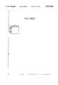
- FIG. 1is a perspective view showing a mobile unit having a PCMCIA connector in accordance with one embodiment of the present invention.
- FIG. 2is a perspective view of a mobile unit having a parallel port connector in accordance with one embodiment of the present invention.
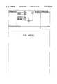
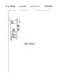
- FIG. 3is a perspective view of an access point unit in accordance with one embodiment of the present invention.
- FIG. 4is an exploded perspective view of a mobile unit having a PCMCIA connector in accordance with one embodiment of the present invention.
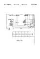
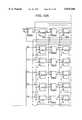
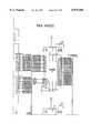
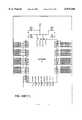
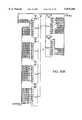
- FIG. 5is a view of the top of a populated printed circuit board of an embodiment of a mobile unit in accordance with the invention as illustrated in FIG. 4.
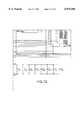
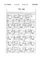
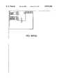
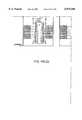
- FIG. 6is a view of the bottom of a populated printed circuit board of an embodiment of a mobile unit in accordance with the invention as illustrated in FIG. 4.
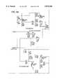
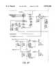
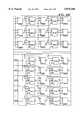
- FIG. 7is a schematic of a digital portion of an embodiment of a mobile unit in accordance with the invention as illustrated in FIGS. 5 and 6.
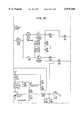
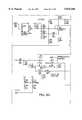
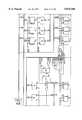
- FIG. 8is a schematic of radio circuitry of an embodiment of a mobile unit in accordance with the invention as illustrated in FIGS. 5 and 6.
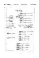
- FIGS. 9A-Dcomprise a high level block diagram of an embodiment of the radio controller ASIC U6 of the schematic of FIG. 7.
- FIG. 10is a schematic diagram illustrating a parallel port embodiment of field programmable gate array component U2 of the schematic of FIG. 7.
- FIG. 11is a schematic diagram illustrating a PCMCIA embodiment of field programmable gate array component U2 of the schematic of FIG. 7.
- FIG. 12is a diagram illustrating a directed MPDU communication and a multicast MPDU communication between two units.
- FIG. 13is a diagram illustrating a directed MPDU communication between two units.
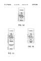
- FIG. 14is a diagram illustrating a general format of a header.
- FIGS. 15-19are diagrams illustrating a format of an RTS frame, a CTS frame, a DATA frame, an ACK frame, and an announce frame, respectively.
- FIG. 20is a diagram illustrating a multicast MPDU communication between two units.
- FIGS. 21-24are diagrams illustrative of a synchronization of units in accordance with one embodiment of the present invention.
- FIG. 25is a diagram illustrating roaming.
- FIG. 26is an instance diagram of one embodiment of software executing in an access point unit in accordance with the present invention.
- the instance diagramis associated with the roaming illustrated in FIG. 25.
- FIG. 27is a diagram illustrating the relationship of the asynchronous service and the time bounded service to higher and lower level protocols.
- FIG. 28is an illustration of an inbound MPDU of the time bounded service in accordance with one embodiment of the present invention.
- FIG. 29is an illustration of an outbound MPDU of the time bounded service in accordance with one embodiment of the present invention.
- FIGS. 30-33are diagrams illustrating a format of a RTSI frame, a CTSI frame, a RTSO frame, and a CTSO frame, respectively.
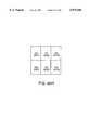
- FIG. 34is a diagram illustrating access point units managing bandwidth in accordance with the time bounded service in accordance with the present invention.
- FIGS. 35 and 36show two embodiments of the mobile unit in FIG. 1 inserted into a PCMCIA slot.
- FIG. 37is a diagram illustrating the operation of time bounded service in overlapping service areas in accordance with the present invention.
- FIGS. 38 and 39are block diagrams of a radio receiver/transmitter circuit in accordance with the present invention.
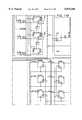
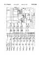
- FIGS. 40A-Mcomprise a schematic of an embodiment of an access point unit in accordance with the present invention.
- FIG. 41is a block diagram of an embodiment of an access point unit in accordance with the present invention.
- FIGS. 42, 43A-43B, and 44are instance diagrams illustrating an operation of access point unit software during a registration of a mobile unit, a handling of a user message, and a discovery of a new access point unit by a mobile unit, respectively.
- a wireless local area network in accordance with the present inventionmay comprise one or more mobile units as well as one or more access point units.
- a mobile unitmay, for example, be coupled to a portable personal computer ("host") so that the personal computer can form part of a wireless local area network.
- the personal computercomprises a PCMCIA port
- a mobile unit having a PCMCIA connectormay be inserted into the PCMCIA port of the personal computer and thereby be coupled to the personal computer.
- the personal computeris provided with a parallel port, then a mobile unit having a parallel port connector may be coupled to the parallel port of the personal computer.
- FIG. 1is a perspective view illustrating mobile unit 1 having a PCMCIA form factor as well as a PCMCIA connector 2.
- Mobile unit 1also provides, however, an antenna extension 3.
- a first light emitting diode (LED) 4 and a second LED 5are provided on the antenna extension 3.
- the mobile unit illustrated in FIG. 1may be inserted into a PCMCIA slot 350 (FIG. 35) of a personal computer (not shown) so that the connector 2 will couple to a corresponding PCMCIA connector of the personal computer.
- FIG. 2is a perspective view of another embodiment 6 of the mobile unit in accordance with the present invention.
- This embodiment 6rather than having a PCMCIA connector 2, has a connector 7 for connecting to a standard parallel port of the personal computer.
- the embodiment 6 of the mobile unit illustrated in FIG. 2also has a first LED 8 as well as a second LED 9 disposed on a antenna extension 10.
- FIG. 3is a perspective view of an access point unit 11 in accordance with the present invention.
- Access point unit 11may, in some embodiments, comprise a telephone jack (not shown) for connecting to a standard wall mounted telephone jack and an associated land line.
- the access point unit 11comprises a mobile unit 1 which is inserted into a slot 12 in a housing of the access point unit 11.
- the mobile unitprovides a radio transmitter/receiver for communicating with mobile unit.
- FIG. 3illustrates that an antenna extension 13 extends from the enclosure of the access point unit 11 in similar fashion to the way an antenna extension 3 of a mobile unit extends from the housing of a host personal computer.
- an access point unit 11is in radio communication with a mobile unit 1 such that a portable personal computer coupled to mobile unit 1 may be part of the local area network to which the access point unit 11 provides access.
- This hardwired local area networkmay comprise mechanical connections between desktop personal computers, other computers, printers, plotters, fax machines, and other peripherals.
- the access point unitsare located throughout an area so that a personal computer provided with a mobile unit can access the hardwired local area network through one or more of the access point units which are within radio communication range of the mobile unit.
- a mobile unitmay be moved throughout the operating area of the hardwired local area network such that the mobile unit moves out of a radio communication range with a first access point unit but moves into a radio communication range with a second access point unit. In this situation the mobile unit is said to be "roaming". Control of the mobile unit may be passed from the first access point unit to the second access point unit in order to maintain communication between the mobile unit and the hardwired local area network to which the access point units are coupled.
- no access point unitsare required to form a local area network.
- the two mobile unitsmay form an "ad hoc" local area network.
- An ad hoc local area networkmay include many mobile units, some of which are not in direct radio communication with other of the mobile units. As long as each mobile unit of the ad hoc network can communicate with each other mobile unit of the network either directly or indirectly through other intermediary mobile units, all the mobile units can be part of the same ad hoc network.
- a user of a personal computer having a mobile unitis able to enter a communication range of either another mobile unit or an access point unit and join the local area network without having to establish any mechanical electrical (wired) connections to the local area network whatsoever.
- the user of the personal computerremoves the personal computer and the attached mobile unit from the radio communication range of the wireless network, radio communication is broken. The local area network continues operating without the departed mobile unit.
- FIG. 4is an exploded perspective view of an embodiment of the mobile unit 1 of FIG. 1 having a PCMCIA form factor and a PCMCIA connector 2.
- a printed circuit board 40is sandwiched between a top cover member 41 and a bottom cover member 42.
- the printed circuit board 40is held in place and somewhat sealed into the PCMCIA form factor by a plastic gasket 43 to which the top cover member 41 and bottom cover member 42 adhere.
- the plastic gasket 43comprises first and second metal electrostatic discharge (ESD) protection contacts 44 and 45 disposed on the edges of the gasket member 43 such that high voltage electrostatic charge on, for example, the hand of a person will be discharged when the person grasps the mobile unit in a natural way between the thumb and forefinger.
- ESDmetal electrostatic discharge
- the gasket member 43has two holes 46 and 47 in a plastic antenna extension 48. These openings 46 and 47 are positioned so that first and second LEDs 4 and 5 disposed on the printed circuit board 40 can be viewed from the outside of the assembled PCMCIA form factor enclosure.
- the PCMCIA connector 2is soldered to one end of the printed circuit board 40 as illustrated in FIG. 4. Details of the electrical components, integrated circuits, and traces of the printed circuit board assembly are not illustrated in FIG. 4 for ease of illustration.
- FIG. 5is a top down view of the top of populated printed circuit board 40 of the mobile unit of FIG. 4.
- the circuit components to the right of the designators A in FIG. 5comprise radio circuitry for both transmitting and receiving information.
- the circuitry and components to the left of the line designated Acomprise digital circuitry associated with coupling the radio circuitry to an PCMCIA port such as a PCMCIA port of a host personal computer (not shown).
- a substantially T-shaped antenna trace 50is illustrated on an antenna extension 51 of the printed circuit board 40.
- FIG. 6is a view of the bottom of the populated printed circuit board 40 of FIG. 4.
- the components and circuitry disposed to the right of the line designated Acomprise part of the radio circuitry whereas components and circuitry to the left of line A comprise part of the digital circuitry which couples the radio circuitry to the PCMCIA port of the host computer. All components are surface mount components.
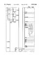
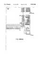
- FIG. 7is a schematic illustrating the digital portion of the mobile unit illustrated in FIGS. 5 and 6.
- FIG. 8is a schematic of the radio circuitry of the mobile unit illustrated in FIGS. 5 and 6.
- the PCMCIA connector illustrated in FIGS. 5 and 6is designated on FIG. 7 by the reference numeral P1.
- the circuitry illustrated in FIG. 7comprises PCMCIA connector P1, a field programmable gate array (FPGA) U2, an 80C188-10 microcontroller U4, a 128K ⁇ 8 flash memory U3, a 32K ⁇ 8 static RAM U5 and a application specific integrated circuit (ASIC) radio controller U6.
- the connections designated with circles to the right of radio controller U6 in FIG. 7designate electrical connections to correspondingly labeled connectors on the radio circuit illustrated in FIG. 8.
- the circuitry of FIG. 11is programmed into the field programmable gate array U2 of FIG. 7. If, on the other hand, the mobile unit is to communicate with a host computer via a parallel port, then the circuitry illustrated in the schematic of FIG. 10 is programmed into the field programmable gate array U2 of FIG. 7 and PCMCIA connector P1 is replaced with a suitable parallel port connector.
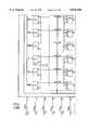
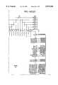
- FIGS. 9A-9Dcomprise a high level block diagram schematic of the contents of the radio controller ASIC U6.
- the Radio Controller ASIC U6is realized in approximately 11,000 gates in a one micron CMOS NEC gate array in an 80-pin thin quad flat pack package.
- External pins of the radio controller ASICare illustrated on FIG. 9A and are designated either with arrowheads, arrow tails, or both.
- Arrowheadsdesignate output pins
- arrowtailsdesignate input pins
- nets having both an arrowhead and an arrowtaildesignate bidirectional pins.
- the squares in the schematic of FIG. 9Aillustrate net connections connecting various identically labelled nets on FIGS. 9A through 9D.
- the output pins illustrated in a column and labelled TXSCRAM through DBRXCRCare diagnostic pins usable to determine information about the operation of the radio controller ASIC.
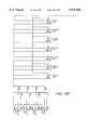
- the block labelled Bus Interface in FIG. 9Bcontains a plurality of registers for communicating to and from the radio controller ASIC. Once a register is written with an appropriate value, the Bus Interface block causes an appropriate signal to be asserted indicative of the particular activity or operating mode the ASIC is to perform or assume.
- the signals to the right of the Bus Interface block labelled RTX1 through RCK0are these signals.
- the registersare accessed by address pins A0-A4 of FIG. 9A and address/data pins D0-D7 of FIG. 9A.
- the block labelled Interrupt Controller in FIG. 9Bprovides an interrupt interface for interrupting the 80C188 microcontroller 04.
- Each interruptis capable of being masked at the control of either microcontroller U4 of the host via lines IMR0 through IMR7 which extend from the Bus Interface block.
- the interrupt request output of the Interrupt Controllerwhich is coupled to the 80C188 microcontroller U4 via pin IRQ0 is labelled HINT.
- the Interrupt Controller blockinterrupts the microcontroller U4 with line HINT and pin IRQ0, the microcontroller can cease program execution and determine the cause of the interrupt by reading lines ISR 7:0! via the Bus Interface block.
- the block labelled TX/RX DMA Controller in FIG. 9Ballows the radio controller ASIC to operate as a slave DMA device at the command of the DMA controller of the 80C188 microcontroller U4. Accordingly, the ASIC may be instructed to supply byte after byte of information from a 5-byte FIFO in the TX/RX DMA Controller block to the radio circuit and to assert a DMA request signal DRQ back to the DMA controller of the microcontroller U4 when the ASIC requires additional bytes to forward to the radio circuit. In such a situation, the TX/RX DMA Controller block is able to determine that a DMA request on line DRQ should be asserted because the ASIC has been programmed with information indicating how many total bytes should be transmitted.
- assertion of the DMA request line DRQ by the DMA Controller block when the ASIC is receiving data from the radio circuitindicates to microcontroller U4 that it should relinquish control of the address bus RA 16:0! and address/data bus AD 7:0! and indicates to the host that the host should empty the FIFO of the DMA Controller in the ASIC.
- the Clock Tree Generator block in FIG. 9Bcomprises a plurality of clock buffers to supply clock signals throughout the ASIC.
- the clock signal CLK10is a one megahertz clock signal which may be increased if required to enable higher data bit rates.
- the Clock/Power Control Unit block of FIG. 9Ballows the mobile unit to be placed into a sleep mode to conserve power and allows the unused ports of the radio circuit to be unpowered to conserve power.
- the radio receiver portion of the radio circuitryis not being used.
- the Clock/Power Control Unitcan therefore cut power to the receiver portion of the radio circuit to conserve power.
- the digital circuitry in the ASIC associated with receiving an incoming radio signalis not used. This digital circuitry is therefore not clocked so as to conserve power.
- a register in the Bus Interface blockmay also be written to change the clock frequency of CLK10 output by the Clock/Power Control Unit block to the Clock Tree Generator block.
- the LED Interface block of FIG. 9Bcauses the two LEDs on the antenna extension of the mobile unit to light under appropriate conditions.
- One LEDblinks when information is either being transmitted or received by the mobile unit. This LED may therefore be considered to be an indication of "activity”.
- the other LEDis turned on to indicate that the mobile unit has registered with an access point unit, and has been authenticated. This LED therefore indicates that the mobile unit is "linked” into a hardwired local area network by an access point unit.
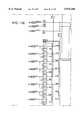
- the blocks of FIG. 9Ccan be grouped into a data flow group and a control group.
- the data flow groupcomprises the blocks labelled Transmit FIFO, Parallel-Serializer, TX CRC Generator, TX Serial Mux and Data Scrambler.
- the control blockscomprise the blocks labelled Pre-Transmit FSM, Transmit Core FSM, Transmit Down Counter, Post-Transmit Logic and TX Enable Mux.
- FSMare an acronym for finite state machine.
- Serial bitsare supplied out of the Parallel-Serializer block on the signal line indicated TXSOUT.
- the serial data bit streamis supplied through the TX-Serial Mux to the Data Scrambler.
- the TX Serial Muxis switched so that a CRC code which is generated for the preceding serial bit stream is appended to the end of the serial bit stream.
- the CRC bitsare therefore also supplied to the Data Scrambler.
- the Data Scramblercontains a linear feedback shift register for generating a pseudorandom sequence of bits from an incoming sequence of bits based on a key received on bus lines KEY 15:0!.
- KEY 15:0!is controlled by writing an appropriate register in the Bus Interface block of FIG. 9B.
- the other blocks illustrated in FIG. 9Ccontrol the five data flow blocks in accordance with the frame formats described below to generate the output serial bit stream on the conductor labelled TXD of the Data Scrambler Block.
- the Pre-Transmit finite state machineis activated by the signal TXFRAME, TXFRAME is asserted by writing an appropriate register in the Bus Interface block. TXFRAME is an indication that something is to be transmitted.
- the Pre-Transmit state machinetherefore asserts TX1 through the TX Enable Mux block to switch the radio circuit to transmit as opposed to receive. Some time later, the Pre-Transmit finite state machine will assert TX2 high that will turn power on to the transmitter of the radio circuit. After a period of time, TX3 is asserted to start modulating information into the radio transmitter.
- the Transmit Core FSMoperates to read the FIFO of the Transmit FIFO block and to load the Parallel-Serializer every eight microseconds.
- the Transmit Down Counter blockis decremented once upon serialization of each byte.
- the Post-Transmit Logic blockenables the Tx CRC Generator to append the CRC bits and then issues an end of frame ENDOFFRAME interrupt to the 80C188 microcontroller indicating that the frame has been transmitted.
- FIG. 9Dillustrates a data path and associated control for receiving a serial bit stream into the ASIC from the radio circuit.
- the incoming serial bit streamis supplied to a Frame Detector/Descrambler/Parallelizer block on the conductor labelled RXD.
- Frame Detector Descrambler/Parallelizersynchronizes a block to a preamble sequence of incoming alternating ones and zeroes, detects a frame delimiter bit sequence, determines from the header of the incoming frame whether or not data bits follow, determines where in the frame those data bits are located, descrambles any following data bits based on a key which is supplied on bus KEY 15:0!, and assembles the resulting bits into parallel bytes which are output from the block on the data bus labelled RXDATA 7:0!.
- a clock signalis also received from an incoming stream of bits which is described in further detail in the cop ending U.S.
- the RX CRC Generator blockchecks the sequence of incoming bits with the incoming CRC bits.
- the Parser blockreceives the sequence of data bytes RXDATA 7:0! from the Frame Detector/Descrambler/Parallelizer and parses the various bytes of the frame being received.
- the Parseralso determines whether the frame being received is an Announce frame, an RTS frame, a CTS frame, a Data frame, or an ACK frame.
- a 13-byte deep Receive FIFOis provided to buffer successive bytes received on the bus RXDATA 7,0! so that they can be read on bus RXFIFO 7:0!.
- the Receiver Core FSMwrites a byte of parallel information once every eight microseconds into the Receive FIFO block.
- the Receive FIFOis 13 bytes long as opposed to 5.bytes long like the transmit FIFO so that when the microcontroller is very busy, the radio controller ASIC will be able to receive and store an entire RTS, CTS or ACK frame without suffering a FIFO overflow.
- the hosti.e. portable personal computer connected to a mobile unit
- the hostmay wish to send a frame comprising a number of bytes over the radio link to another mobile unit or to an access point unit on a local area network.
- Bytes of the frameare written by the host one by one into the field programmable gate array U2 in a memory mapped fashion over the bus of the host and through connector P1.
- the field programmable gate arraycontains the bytes of information
- the field programmable gate array U2requests a DMA transfer by asserting line DRQ0 on pin 90.
- the 80C188 microcontroller U4receives the DMA request from the field programmable gate array on pin 79 and relinquishes control of the address bus RA 16:0!
- the Tx/Rx DMA Controller of FIG. 9B of ASIC U6may assert a DMA request DRQ by generating a DMA request from pin 53 to the DRQO pin 76 of microcontroller U4.
- the DMA controller of microcontroller U4will then read bytes of information from the Receive FIFO of ASIC U6 and write those bytes to the field programmable gate array U2.
- the microcontroller U4executes software residing in flash memory U3 and/or RAM U5.
- the software executed by the 80C188 microcontroller U4is set forth in Microfiche Appendix A, the contents of which are a part of this specification.
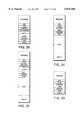
- File RESTART.ASMcontains code that executes initially to set up 80C188 microcontroller U4, to do housekeeping, and to initialize hardware of the mobile unit including registers in the radio controller ASIC U6 and registers in the field programmable gate array U2 which interfaces with the host.
- File HWDEF.INCcontains definitions used by RESTART.ASM to initialize hardware.
- TASKEXEC.ASMis a task executive program which allows multiple tasks to run separately in a multithreaded environment. It also facilitates intertask communication and synchronization so that different tasks can set events for one another, wait for events that are set by other tasks, send messages to other tasks, suspend themselves pending messages from other tasks, and suspend themselves pending events that are triggered by interrupt routines.
- the file HOSTISR.ASMcontains a task that handles the host interface. Both parallel port and PCMCIA field programmable gate array interfaces are supported. HOSTISR.ASM comprises an interrupt service routine that performs the necessary handshaking to allow the host to read information including status information from the programmable gate array U2 which interfaces to the host.
- the file HSTTXTSK.ASMcontains a task which receives an Ethernet-type packet from the HOSTISR.ASM, and fragments the packet as necessary into smaller units. The task MACTXTSK.ASM converts the fragmented packets into frames which are consistent with a communication protocol.
- MEDIAISR.ASMcontrols the radio controller ASIC U6 and the associated radio circuit of FIG. 8 to transmit the frames generated by MACTXTSK.ASM.
- MEDIAISR.ASMcomprises an interrupt service routine that initiates the transmission of frames from the radio controller ASIC U6, handles reception of frames from the radio controller ASIC U6, and handles transmit and receive errors.
- MEDIAISR.ASMcontrols the radio controller ASIC U6 to receive a frame
- the frameis passed to MACTXTSK.ASM.
- MACTXTSK.ASMdecodes and dissembles the frames in accordance with a communication protocol into packets (small units). These units are then passed to HSTRXSK.ASM.
- HSTRXSK.ASMthen assembles the small units back into either host Ethernet-type packets or another format in which the host is expecting to receive information.
- HOSTISR.ASMthen handles the communication of the packets to the host via the field programmable gate array U2.
- HOSTDEF.INCcontains definitions including register addresses within the field programmable gate array U2 and bit definitions of the registers within the field programmable gate array U2.
- MEDIADEF.INCcomprises a plurality of definitions including register addresses within the radio controller ASIC U6 and bit definitions of the registers inside the radio controller ASIC U6.
- SCHEDULE.ASMcomprises an interrupt routine which controls frequency hopping and ad hoc initialization.
- ENVIRONMENT.INCdefines the events that tasks can set by one task for another task.
- MACDEF.INCcontains definitions related to the protocol which defines the format of frames including the lengths of the various frames and the meanings of the various fields within the various frames.
- GLOBALS.INCcontains a list of functions and variables that are shared between tasks. DIAG.INC contains a number of diagnostic routines for testing.
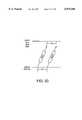
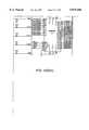
- FIG. 12illustrates two units, one of which may be an access point unit, properly synchronized with each other in both time and frequency so that they are part of the same wireless local area network. Communication between units number 1 and number 2 is divided into hops.
- FIG. 12illustrates two hops, hop number X and subsequent hop number X+1. Each of the hops is 100 milliseconds in duration.
- the unit transmitting and the unit receivingmust be tuned to the same frequency.
- FIG. 12illustrates units 1 and 2 tuned to frequency A in hop number X and tuned to frequency B in subsequent hop number X+1.
- the units of a networktransmit by repetitively sequencing through 82 hops, each of the 82 hops having a different frequency and having a duration of 100 milliseconds. Each frequency is used exactly once during one repetition of a hopping sequence.
- Hop number X in FIG. 12illustrates a directed MPDU.
- the directed MPDUcomprises a request to send (RTS) frame transmitted from unit number 2 to unit number 1, a clear to send (CTS) frame transmitted from unit number 1 back to unit number 2, a data frame (DATA) transmitted from unit number 2 to unit number 1, and an acknowledge (ACK) frame transmitted from unit number 1 to unit number 2.
- RTSrequest to send
- CTSclear to send
- DATAdata frame
- ACKacknowledge
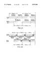
- FIG. 13illustrates a directed MPDU communication in greater detail.
- a directed MPDUis sent to a specific unit from a specific unit.
- Each directed MPDUgenerally consists of four frames: a RTS frame, a CTS frame, a DATA frame, and an ACK frame.
- RTSis used to reserve the communication channel for transmission of the DATA frame.
- RTSis able to reserve the communication channel because the RTS frame contains a destination address uniquely identifying the unit to which a following DATA frame is to be sent as well as a data length field.
- Other units receiving the RTS frame but which are not identified as the destinationtherefore are able to compute the amount of time required for the MPDU communication to be completed. The other units will therefore not attempt to use the communication channel during this period and the channel will be reserved.
- CTSis a transmission from the destination unit which is used to indicate that the destination unit can receive the DATA frame.
- the DATA frameis used to transmit the data of the MPDU communication to the designated unit.
- the ACK frameis used to acknowledge that the DATA frame was received without error.
- the radio circuit illustrated in FIG. 8requires about 50 microseconds to switch from a transmit mode to a receive mode.
- the minimum time between successive framesis therefore at least 50 microseconds.
- the maximum value of timeouts T1, T2 and T3are as small as possible.
- T1(the CTS timeout period) is the maximum time that a second unit will wait for a CTS frame after sending an RTS frame.
- T3(the ACK timeout period) is the maximum time that a sending unit will wait for an ACK frame after transmitting the DAT frame.
- T2 (the DATA timeout period)is the maximum time that a receiving unit will wait for a DATA frame (250 microseconds maximum).
- T1 and T3each have a duration of 50 to 100 microseconds.
- FIG. 14is a diagram of the general header format used in all asynchronous service MPDU frames.
- An unique 8-bit Start Frame Delimiter (SFD) having a specific pattern of 10101011follows the preamble and is used to determine that the received radio signal is in fact a frame to be received and not random noise that happened to cause the radio receiver to lock and to provide a demarkation of the beginning of the information to follow.
- SFDStart Frame Delimiter
- the headeris the following seven bytes comprising the TYPE, CONTROL, DATA LENGTH, HOP TICK, NETID, and SEQNUM fields. These fields are transmitted with the most significant byte first and, with most significant bit first. A cyclic redundancy check (CRC) is also appended to each frame.
- CRCcyclic redundancy check
- the TYPE fieldindicates whether the frame is an RTS, CTS, DATA, ACK, or ANNOUNCE frame.
- the TYPE fieldalso indicates the MPDU type.
- the CONTROL fieldis a 6-bit field which describes the type of service and the structure of the wireless network.
- the DATA LENGTHis a 10-bit field which indicates the number of bytes in the DATA frame of the MPDU.
- the HOP TICK fieldindicates the number of ticks remaining in the current hop. Each tick represents 1/256 of the hop length. HOP TICK may be used by other units to synchronize their 100 millisecond hops in time so as to correspond to 100 millisecond hops of the transmitting unit.
- the NETID fieldis a 16-bit number that identifies the particular wireless network to which the sending unit belongs.
- Multiple different wireless networksmay therefore operate at once in overlapping service areas provided that each network uses a different NETID.
- a NETID of OFFFFhindicates that the sending unit does not belong to any network.
- a group of unitscan therefore communicate without agreeing on a NETID.
- the field SEQNUMis an 8-bit sequence number used for duplicate detection. The sending unit increments this field on transmissions of each number MPDU.
- the TYPE fieldin turn has two subfields: Frame Type and MPDU Type.
- Frame Typeis the high order 4 bits and MPDU Type is the low order 4 bits.
- the most significant two bits of the MPDU Type subfield of the TYPE fieldare reserved.
- the next most significant bitis the ENCRYPT bit and the least significant bit is the SYSPKT bit.
- An ENCRYPT bit of "1"indicates that the data portion of the MPDU is encrypted.
- An ENCRYPT bit of "0"indicates that the data portion of the MPDU is not encrypted.
- a SYSPKT bit of "1"indicates that the current MPDU should be processed by the microcontroller of the mobile unit.
- a SYSPKT bit of 0indicates that the current MPDU data should be passed to the host.
- the Frame Types designated by the first four bits of the TYPE fieldare as set forth in Table 1 below:
- the bits of the CONTROL fieldalso are broken down into subfields.
- the bits, listed from highest order to lowest order,comprise: a TB bit, a HIERARCHICAL bit, an AP bit, a RETRY bit, two reserved bits, and the two most significant bits of the DATA LENGTH field.
- a TB bit of "0"indicates that this MPDU is for asynchronous service and not for time bounded service.
- a TB bit of "1"indicates that this MPDU is for time bounded service which defines a special format of the rest of the frame.
- a HIERARCHICAL bit of "1"indicates that the MPDU will only be received by access point units. Access point units always clear the HIERARCHICAL bit before relaying an MPDU.
- the HIERARCHICAL bitis used to force asynchronous traffic through an access point unit.
- An AP bit of "1"indicates that the current MPDU was sent by an access point unit.
- the AP bitallows wireless units to distinguish between an MPDU sent directly and one that has been forwarded by an access point unit.
- a RETRY bit of "1"indicates that the current MPDU is a retransmission of an earlier MPDU.
- FIG. 15is a diagram showing the various fields comprising an RTS frame.
- RTSor Request-To-Send, is a transmission from a source unit to a destination unit which initiates the MPDU. It is a fixed length frame of 14 bytes (not counting the preamble and SFD byte).
- the field TYPEhas a format of 0x, where x is the MPDU Type.
- HOP TICKis the HOP TICK of the transmitting unit.
- the DATA LENGTH fieldis not the length of this frame but rather it is the length of the payload of the DATA frame that will be sent if the source unit receives a CTS frame.
- DESTINATION ADDRESSis the 48-bit unique identification code which uniquely identifies the destination unit.
- CRC 8is an 8-bit cyclic redundancy check which is computed on the RTS frame.
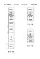
- FIG. 16is a diagram showing the various fields comprising a CTS frame.
- CTSor Clear-To-Send, is a transmission from the destination unit to the source unit granting permission to transmit the DATA frame.
- CTSis not used for flow control in this context.
- CTSindicates that the destination unit can hear the source unit and is ready to receive the DATA frame. There is no implication about the availability of buffers in the receiving unit.
- CTSis important for "carrier sense" in a wireless network because it conveys the length of the data frame to those wireless units that can hear the destination unit but not the source of the MPDU.
- the TYPE fieldhas the format of 2x, where x is the MPDU Type.
- CRC 8is an 8-bit cyclic redundancy check computed on the CTS frame.
- FIG. 17is a diagram showing the various fields comprising a DATA frame.
- DATAis a transmission from the source unit to the uniquely identified destination unit that contains the data "payload" of the MPDU.
- the payloadmay be from 1 to 576 bytes in length as specified by the DATA LENGTH field, not counting the preamble and SFD byte.
- the total length of the DATA frameis: 7+12+4+DATA LENGTH bytes. Seven bytes are provided for the header, 12 bytes for SOURCE ADDRESS and DESTINATION ADDRESS, and 4 bytes for the CRC 32 field.
- the TYPE fieldhas the format of 8x, where x is the MPDU type.
- DATAis a variable length field specified in the DATA LENGTH field of the RTS, CTS, DATA and ACK frames.
- the minimum DATA LENGTHis 1 byte.
- the maximum DATA LENGTHis 576 bytes.
- CRC 32is a thirty-two bit IEEE 802 standard cyclic redundancy check sequence on the DATA frame.
- FIG. 18is a diagram showing the various fields comprising a ACK frame.
- An ACKis a transmission from the destination unit to the source unit that acknowledges receipt of the DATA frame with a correct MPDU check sequence. Negative acknowledgments are not used in the protocol.
- An ACK framealways indicates successful receipt of the DATA frame.
- the ACKis a fixed length frame of 8 bytes not counting the preamble and SFD byte.
- the TYPE fieldis of the form 4x, where x is the MPDU Type.
- hop number X of FIG. 12illustrates an example of a directed MPDU
- hop number X+1 of FIG. 12illustrates an example of a multicast MPDU.
- a multicast MPDUconsists only of two frames: an RTS frame and a DATA frame.
- FIG. 20illustrates a multicast MPDU communication in greater detail.
- a multicast MPDUis an MPDU which is destined for more than one receiving unit.
- a multicast MPDUmay have a group address in which case it is directed to a group of receiving units.
- a multicast MPDUmay be called a broadcast MPDU which has an address directed to every receiving unit.
- Multicast MPDUsdo not have a specific destination unit to provide return CTS or ACK frames. If all receiving units transmitted return CTS and ACK frames, there would likely be collisions.
- the unit sending a multicast MPDUinserts a delay of time T4 between the transmission of the RTS frame and the transmission of the DATA frame.
- T4is the interframe gap (IFG) time plus the time required to transmit a CTS frame.
- IGFinterframe gap
- T4is 154 microseconds.
- the frame formats for multicast RTS and DATA framesare the same as the frame formats for RTS and DATA frames of directed MPDUs.
- a positive acknowledge protocolis used. Low level acknowledgments are used to improve the reliability of the wireless medium.
- the source unitexpects an ACK after the DATA frame. If an ACK is not received within 100 microseconds, the ACK is assumed lost and the MPDU is scheduled for retransmission. This process is repeated 9 times. If no ACK is received after the ninth attempt, a send failure is reported. Broadcast and multicast MPDUs do not expect ACKs and are never retransmitted. The retransmission method is enhanced to work better with the spread spectrum frequency hopping of the radio circuit. Sending stations retransmit directed MPDUs up to three times on a particular frequency.
- a sending unitwill wait until its radio hops to the next frequency before sending additional retransmissions. This minimizes the effect of narrow band interference because a sender will attempt to transmit on a least three different frequencies before aborting a transmission.
- the communication protocol employeddetects and filters out duplicate MPDUs and conserves channel bandwidth. Transmitting units do not send a new MPDU during retransmission attempts of a previous MPDU. There is only one MPDU outstanding per sending unit.
- the receiving unitmay receive MPDUs from other units interleaved with retransmissions from one unit.
- Every receiving unithas a time out for receiving a DATA frame.
- the data frame timeout T2is illustrated in FIG. 13 as T2. Every unit that receives an RTS frame will set its NetBusy and the NetBusy timer. If a corresponding DATA frame is not received within 250 microseconds, the NetBusy flag will be cleared immediately. This limits the reservation time of an RTS frame that is not followed by the rest of the MPDU such as conditions when a unit attempts to transmit to another unit that is no longer on the network.
- LBTListen Before Talk
- CSMA/CD protocolssuch as Ethernet reduce this wasted bandwidth by detecting the collision early in the frame by using a Listen While Talk (LWT) protocol and aborting the transmission as soon as a collision is detected.
- LWTListen While Talk
- the above-described RTS/CTS exchangeis used to resolve channel contention. After an RTS/CTS exchange, any unit that "heard" either frame will not attempt a transmission until the rest of the MPDU is finished. This eliminates collisions during the DATA frame. If collisions do occur, they will occur during the subsequent RTS frame when multiple units determine that the channel is free and determine to initiate a transmission at the same time. However, because an RTS frame is only 13 bytes long, wasted bandwidth is minimal. If an RTS frame is garbled, no CTS frame will be sent for colliding RTD frames and the source unit will be able to determine that the transmission must be sent again.
- the source unitWhen a CTS frame is not received by a source unit, the source unit assumes that a collision occurred and schedules a retransmission of the MPDU.
- An ACK frame not being received by the source unitindicates that either the DATA frame was damaged or that the ACK frame itself was damaged. In either case, the source unit must retransmit the entire MPDU.
- Retransmissions from different unitsmust, however, not be sent at the same time or they will cause another collision. Each unit therefore delays its retransmission for a random amount of time in order to reduce the probability of another collision. The delay before a retransmission is called the backoff time. On the first transmission attempt, there is no backoff time. The source unit retransmits as soon as the channel is detected to be free. For all retransmission attempts of the same MPDU, however, the source unit waits random backoff time before sending the RTS frame.
- the backoff timeronly counts down when the NetBusy flag is false.
- the sending unitcomputes a random number, scales this number, and uses it to set the initial value of the backoff timer.
- the backoff timeis a multiple of the "slot size".
- the slot sizeis the time required to reserve the channel for the transmission of a DATA frame. In some embodiments, the time required to reserve the channel is the length of an RTS frame, plus the length of a CTS frame, plus some overhead for the interface gap (IFG).
- the following pseudocodeillustrates a method of determining the backoff time.
- the variable SlotSizehas a value of 360 microseconds which equals the length of an RTS and CTS frame plus overhead.
- WaitTime(Random() MOD MaxSlots) * Slotsize;
- WaitTimeis the number of microseconds to wait.
- the variable MaxSlotshas a value of 16.
- Random()is a function that returns a random number. The unit ID number is used as the seed for the random number generator. After the backoff timer elapses, the source unit senses the channel again and retransmits as soon as the channel is available.
- This method of determining a backoff timehas two desirable properties. First, source units delay their transmissions for a longer time when the network is busy. The network therefore automatically remains stable under heavy loads because the WaitTime will not elapse unless the network is idle. Second, the method eliminates the "clustering" which may occur when multiple units are waiting to transmit and their backoff timers elapse during the transmission of a long frame. Even though those backoff timers may elapse at different times, the transmission attempts will be clustered at the same time, just after the end of the long frame. Because the backoff timer set forth above will not count down during the transmission of a frame, clustering is avoided. There are no retransmissions for broadcast or multicast packets.
- the following pseudocodedescribes the operation of the wireless network protocol used by mobile units and access point units in more detail.
- hardware and softwareare assumed to be synchronized and the pseudocode is executed exactly as fast or as slow as required.
- Many of the software timer loops in the examplesare implemented by hardware in the preferred embodiment illustrated in FIG. 7.
- FIG. 12shows such a synchronization between two units.
- the first unitWhen a first unit is brought into radio communication range with a second unit that is already part of a network so that the first unit can join the network of the second unit, however, the first unit may be tuned to a different frequency than second unit and the 100 millisecond hop periods of the two units may be offset in time with respect to each other.
- FIG. 21illustrates hops of a mobile unit and an access unit.
- the mobile unitwishes to join the network of the access point unit.
- the access point unitis a unit operating on an existing network.
- the two unitsare not yet synchronized in frequency and time in the first 100 millisecond period of the mobile unit illustrated in FIG. 21.
- there are 82 different sequenceswhich may be used by a network to pass through the eighty-two hop frequencies: 2401, 2402 . . . 2482 MHz.
- Sequencesmay be constructed as hyperbolic hop codes as described in "Frequency Hop Codes with Nearly Ideal Characteristics. . .” by Marin and Titlebaum, IEEE Transactions on Communications, September 1992.
- the access point unit in FIG. 21is illustrated as having a sequence including a subsequence of frequency A, frequency B, and frequency C. Providing multiple hopping sequences allows for multiple different wireless networks to operate in the same radio communication area. Each unit therefore must be able to determine the particular sequence being used by the particular network of which it is to be a part.
- the mobile unitreceives a frame from the access point unit.
- This framemay, for example, be a frame addressed by the access point unit to another unit of the network using sequence Y. Because all frames contain the field NETID, the mobile unit is able to determine from the NETID that the particular hopping sequence being used by the access point unit is hopping sequence Y. If an unregistered mobile unit receives a frame transmitted by an access point, the mobile unit will adopt the NETID of the access point rather than the access point adapting the NETID of the mobile unit, because mobile units do not control access points. Therefore, once the mobile unit in FIG. 21 receives the NETID and determines that it would like to join that network, the mobile unit adopts the hopping sequence Y of the network.
- a unitmay simply tune its receiver to one of the 82 hop frequencies until a frame transmission is received.
- a new mobile unittunes its radio receiver to receive on all 82 frequencies over multiple hop periods in a total amount of time period equalling less than eighty-two 100 millisecond periods. This reduces the maximum amount of time required for a new unit to detect a frame transmission.
- Such scanningmay be accomplished by cycling through a default randomly chosen hopping sequence, lingering on each frequency for 20 milliseconds or until a NETID is received.
- each frame transmittedalso contains a HOP TICK field.
- the value HOP TICKis loaded with the value 255 at the beginning of each hop. Every 1/256 of a hop, the unit decrements HOP TICK by one.
- HOP TICKreaches zero, the unit tunes its radio to the frequency of the next hop, and loads HOP TICK with a value of 255.
- Unitstransmit in the HOP TICK field of the frames they transmit the current value of their HOP TICK. Accordingly, the mobile unit of FIG. 21 which is attempting to join a network of which the access point is a member, can determine from the HOP TICK field of a received frame where the access point unit is located in its current 100 millisecond frequency hop.
- the mobile unitis therefore able to synchronize with the access point unit (as well as other units which are part of a network with the access point unit) by adopting the value of HOP TICK transmitted from the access point unit and by using the hopping sequence determined from NETID.
- the mobile unitis illustrated in FIG. 21 switching to the sequence Y of unit number 2 after the reception of a frame in the first 100 millisecond period of the access point unit so that the mobile unit is using sequence Y and frequency B by the second 100 millisecond period of the access point unit.
- the access pointstransmit announce frames every 10 milliseconds.
- all unitsmaintain a count of the MPDUs they have received during a hop.
- every unitcomputes a random number R. If a unit has heard less than 4R frames when the HOP TICK matches R, the unit transmits an announce frame. This method of the mobile units transmitting announce frames does not reduce the efficiency of the network because it is only evoked when there is little or no useful data traffic being sent over the network.
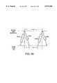
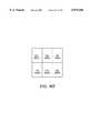
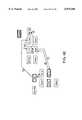
- FIG. 28illustrates a situation in which two mobile units, neither of which is part of a network, are brought into radio communication range to form a network. Because no access point unit is involved, the network to be formed as described above is called an "ad hoc" network. Mobile unit 1 and mobile unit 2 are initially transmitting on different frequencies and are out of synchronization in time. The two units are also initially using different hop sequences.
- Both mobile unit 1 and mobile unit 2transmit announce frames (indicated as arrows in FIG. 23) at least once every e.g. 5 milliseconds because no network activity has been received by either mobile unit in the past. If both units were to remain in one frequency hop of the 82 frequency hops transmitting and receiving, it is likely that the two units would never receive each other's announce frames. Similarly, if each of the two units were simply to transmit and receive at the frequency of its current hop, then it would also be likely that the two units would not receive the announce frames from one another. Mobile unit 1 could be transmitting and receiving in hop 1 at frequency A while mobile unit 2 would be transmitting and receiving in hop 3 at frequency C. When mobile unit 1 switched to hop 2 and frequency B, mobile unit would switch to hop 4 and frequency D.
- each mobile unitreceives at multiple different frequencies (called scanning) during each hop. Because announce frames are guaranteed to occur at least every 5 milliseconds if no other transmission activity is present, and if other activity is present the typical frame duration is 5 milliseconds, a frequency is scanned for a period of 5 milliseconds. In the embodiment illustrated in FIG. 22, four different frequencies are scanned at the end of each 100 millisecond period, each for a period of 5 milliseconds. This is the situation described above in which multiple frequencies are scanned each hop so that all 82 hop frequencies can be scanned in less that eighty-two 100 millisecond hop periods.
- FIG. 23illustrates a situation in which each of the two such mobile units would not, however, receive a frame from the other within eighty-two 100 millisecond periods.
- the two mobile unitshappen to be substantially synchronized with each other in time so that the scan periods of the two mobile units exactly coincide. Neither mobile unit would be transmitting during the scan periods of the other.
- the mobile unitsdo not scan and/or transmit identically during all hops.
- Each mobile unitmay, for example, use a table such as set forth below to determine whether it is to scan or to transmit in the current hop.
- a "1" in the Scan/Transmit columndesignates a scan whereas a "0" designates a transmit.
- Each hop numbercorresponds with one of the eighty-two frequencies at which the units may receive and transmit.
- the scan values of a table such as Table 2may be selected to have a maximum number of situations where one mobile unit is s scanning and other mobile unit is transmitting for each possible spacing of hops between two mobile units. If, for example, the mobile unit 1 is two frequency hops ahead of the mobile unit 1 as illustrated in FIG. 24, mobile unit 1 may be in hop number 80 and mobile unit 2 may be in hop number 78.
- the mobile unitsimply adopts the NETID and HOP TICK of the access point unit. If, however, a mobile unit is not able to form a network with an access point, then the mobile unit attempts to form an ad hoc network with another mobile unit that is not already associated with an access point. But where two mobile units come into contact, it must be determined which hopping sequence and HOP TICK will be adopted for the ad hoc network.
- the mobile unit having the smaller hop numberwill adopt the HOP TICK and hop frequency of the mobile unit having the larger hop number. This determination of the hop frequency of which mobile unit will be adopted must, however, always result in the same hop frequency being determined to be the hop frequency of choice by all mobile units at all times in the sequence.
- FIG. 24illustrates a situation where the hop numbers of mobile unit 1 and mobile unit 2 are offset with respect to each other by 2.
- mobile unit 1When mobile unit 1 is in hop number 81 and mobile unit 2 is in hop number 79, mobile unit 1 would have the hop number of choice because hop number of 81 would be the greater hop number of the two mobile units. 100 milliseconds later in time when mobile unit 1 would have a hop number of 0 and when the mobile unit 2 would have a hop number of 80, however, mobile unit 2 would have the hop number of choice because hop number 80 is the greater hop number.
- the determinationis made based upon the hop numbers of the two mobile units at a location in the sequence where the separation in hop number between the two mobile units is smallest.
- the determinationcould be made based upon the hop numbers where the separation is the largest.
- the two mobile unitshave a hop separation of 2 when mobile unit 1 is in hop number 81 and have a separation of 80 when mobile unit 1 is in hop number 0.
- the hop frequency of mobile unit 1is therefore determined to be the hop frequency of choice because in the hops of smaller hop separation, mobile unit 1 has the greater hop number. After making this determination, mobile unit 2 will adopt the hop frequency of mobile unit 1.
- the multiple mobile unitsIn the event that there are multiple mobile units in a network and the new mobile unit is determined to have the hop frequency of choice, then the multiple mobile units all change their hop frequencies to the hop frequency of the new mobile unit. In this way, a large number of mobile units attempting to form an ad hoc network will all eventually coalesce to a single NETID and HOPTICK.
- Appendix Dwhich is a part of the present disclosure, is a listing of a pascal program which generated the scanning table of Table 2 set forth above.
- Roamingis a collaborative effort.
- a set of access points and mobile unitscooperate to make roaming as fast and smooth as possible.
- Each access point unitconstructs a table that contains information about other access point units in the system, with the help of the mobile units.
- the information in the tablesdescribes to a mobile unit which access point units are good candidates for roaming and exactly how to tune to and synchronize with each access point unit. Every time an access point unit enters the network, it announces its presence and finds out about all the other access point units that are already in the network. Access points coordinate amongst themselves to ensure that they do not use the same NETID and hopping sequence.
- a mobile unitWhen a mobile unit enters a network with infrastructure (a network with a hardwired interconnect), it finds an access point unit by scanning the frequencies. The mobile unit then attempts to register with that access point unit. If the access point unit authenticates the mobile unit it sends a scrambling key to the mobile unit. The mobile unit loads that key into its memory, and then, the mobile unit's data frames are scrambled as they are transmitted. The mobile unit also receives a copy of the access point table (APTable) if it registers successfully.
- APITableaccess point table
- the mobile unitWhen the mobile unit is idle, it attempts to tune to the other access point units in its table to verify the information in the table and to determine which access point units are the best candidates for roaming. This verification is very brief, about 20 milliseconds per check. After a short time, the mobile unit will have a short list of (e.g. 2 or 3) access point units that it could roam to if necessary.
- the mobile unitIf the mobile unit cannot send messages reliably to its current access point unit, it registers with a new access point unit. The new access point unit will contact the old access point unit over the wired portion of the network and inform the old access point unit that the mobile unit has roamed away. If any messages were waiting for the mobile unit, they are transferred to the new access point unit and then relayed to the mobile unit. If there are no buffered messages, this handoff is very quick, about 20 milliseconds. Once a mobile unit has been authenticated by one access point unit, it does not have to be authenticated again.
- the mobile unitsfirst listen. Specifically, they scan the frequencies in search of an access point unit. As soon as they find an access point unit, they adopt its NETID (network ID number) and hopping sequence and attempt to register. If registration is successful, the mobile unit automatically learns about the other NETIDs that are in use in the same system and can roam to a different access point unit if necessary. If the mobile unit is unable to register with any access point unit, it will attempt to form an ad hoc group (explained in detail above).
- NETIDnetwork ID number
- Access point unitscommunicate with each other over the wired LAN using the access point unit-to-access point unit protocol (carried within the conventional bridge-to-bridge protocol of 802.1D). Before an access point unit starts up its wireless interface, the access point unit will: 1) pick a random NETID (the first one it tries could, for example, be the NETID it used previously) and hopping sequence, 2) find all other access point units connected to the same wired LAN system, 3) multicast a message indicating that a new access point unit is about to use that hopping sequence, and 4) listen to hear any access point units that respond with a conflict message. If there is a conflict, the access point unit repeats the process until it finds a free NETID and hopping sequence. Overlapping the communication ranges of individual access point units on a single network therefore is possible by using different hopping sequences.
- Each NETIDmaps into a hopping sequence. Every network unit (access point unit or mobile unit) has a table of all hopping sequences. If a unit wants to communicate with other units using a particular NETID, it must listen until it hears an MPDU with a matching NETID. One method for quick scanning is to cycle through the hopping sequence backwards, lingering on each frequency for 20 milliseconds or until a matching NETID is found. When a matching MPDU is heard, the other information necessary to synchronize the HOPTICK is also heard. The HOPTICK indicates when to move to the next frequency in the hopping sequence. Units must always receive at least one MPDU before they start transmitting on an active NETID.
- a mobile unitregisters with an access point unit through a message exchange as defined above.
- the mobile unitsends a RegisterFirst message containing information about the identity of the mobile unit.
- the access point unitresponds with a RegisterResponse message. If the registration was successful, the access point unit responds with a RegisterResponse message containing an APTable which describes the wireless environment. If the registration was not successful, the RegisterResponse message contains a NACK rather than the APTable.
- the RegisterFirst and RegisterResponse messagesare the only messages that are transmitted in unscrambled form. All other interactions with the access point unit take place through scrambled messages.
- the access point unit with which the mobile unit has registeredwill relay messages from the wired LAN for the mobile unit and will relay messages to the wired LAN for the mobile unit.
- a registered mobile unitis able to access the wired LAN through the access point unit and unscramble any messages sent using the access point unit's NETID.
- a mobile unitIf a mobile unit is not registered, it is unable to send or receive messages from the wired LAN. It is also unable to interpret messages sent by the access point unit other that the RegisterResponse. An unregistered mobile unit can, however, search for other mobile units that want to operate in an ad hoc network.
- a mobile unitdecides to switch to a new access point unit by a decision made automatically by the mobile unit.
- a mobile unitdecides to switch to a new access point unit when its quality of service through the current access point unit degrades. Quality of service is measured by the number of retries needed to send an MPDU.
- a "pull" methodis used for a handoff of a mobile unit from an access point unit to another access point.
- a mobile unitwishes to roam, it contacts a new access point unit and attempts to register. If registration is successful, the new access point unit contacts the old access point unit over the wire (using the access point unit-to-access point unit protocol) and "pulls" the context of the mobile unit to the new access point unit.
- the roaming mobile unitcontacts the new access point that is on a different hopping sequence by accessing the information that it needs in the APTable.
- Mobile unitsreceive a copy of the APTable each time they register or roam to an access point unit. For each access point unit in the APTable, its hop offset and tick offset are stored. The APTable therefore tells the mobile unit where the new access point unit is relative to the mobile unit's hopping sequence. The information in the APTable allows the mobile unit to tune directly to the new access point unit's current frequency without scanning. Because all access point units on the same network use the same scrambling key, a roaming mobile unit is able to interpret messages from any access point unit on the same network. A mobile unit that has not been authenticated will not be able to roam because it will not understand the scrambled messages from access point units.
- the MPDU TYPE fieldhas a bit that indicates User or System Packet. If the bit is zero, the MPDU contains user data and the payload is passed to the host. If the bit is one, it is a System Packet. This bit is used to differentiate between MPDUs that should be processed by the unit firmware and MPDUs that should be passed to the host.
- Power managementis realized by a two message exchange.
- a mobile unit that will be operating in low power modesends a SleepRequest message to its access point unit. If there are messages pending in the access point unit for that mobile unit, the access point unit will reply with a SleepNotOk message and will forward the remaining messages. If there are no messages pending and resources are available, the access point will respond with a SleepOk message.
- the SleepRequest messagecontains a parameter that indicates the duration of the requested sleep time. While the mobile unit is "sleeping", the access point unit buffers any messages that are intended for the mobile unit. When the mobile unit wakes up, the mobile unit sends a WakeUp message to the access point unit and normal operation resumes. There is also a ForcedSleep message that the mobile units may send in an emergency situation such as when they are about to lose power and have no control over the loss of power. There is no response from the access point unit for a ForcedSleep message.
- the client workstationinitiates the data transfers.
- the clienttherefore can control when its network interface will be idle.
- the only unexpected messages received by the clientare watchdog packets from the server. These watchdog packets are used by the server to verify that the client is still there. If the client does not respond within a specified amount of time, the server will terminate the session. If such a file server is operating on a network comprising an access point unit and an associated mobile unit, the access point unit may respond to watchdog packets addressed to the sleeping mobile units instead of simply buffering them and allowing the server to terminate the session.
- the APTableis an array containing elements of the following structure:
- Access point unitskeep track of each handoff that they are involved in (to or from this access point unit) during roaming. After a short period of time, an access point unit has a complete list of all of the other access point units that it is possible to roam to--the "likely neighbor” list. This list will include access point units that are out of radio range of the source access point unit and even some access point units that are reachable only by going through a dead area.
- the "likely neighbor" listis encoded in the APTable by setting the neighborstatus field to "near.”
- a mobile unitEach time a mobile unit registers with an access point unit, it gets a copy of that access point unit's APTable. This occurs when the mobile unit first enters the system as well as each time there is a handoff. Mobile units therefore quickly learn about their changing environment as they move around the system. Access point units alone can not provide the hopOffset and the tickOffset, because they are not able to hear all of the other access point units over the wireless medium. This dynamic information must be supplied to the access point units by the mobile units.
- Mobile unitsscan the radio frequencies to determine the relative timing of the other access point units. This is also known as the "break" approach. Mobile units occasionally go off line when they are idle and listen to other frequencies. They linger on each frequency until they hear any MPDU from or forwarded by an access point unit, or until 10 milliseconds has passed. Eventually, they will hear all of the access point units that are within range. Mobile units occasionally do a "complete scan” of all of the frequencies in the manner described above during a single "break” to look for new access point units coming within communication range. It is not guaranteed that every access point unit within range will be heard because access point units continue to hop during a scan and each will hop eight times during a complete scan. A single, "complete scan” will not usually find all of the available access point units. Several short scans work as well as a single long scan.
- Mobile unitsalso periodically do "short scans" to look for known neighboring access point units. After several short scans, they will have heard every possible known access point unit. It has been found that 100 milliseconds is a convenient duration for the scan, since a mobile unit could simply skip a hop while scanning. The mobile units do not send messages when they scan; they simply receive. If a scanning mobile unit receives any MPDU from an access point unit, it can determine the hopOffset and tickOffset.
- Units using a given hopping sequencevisit each frequency exactly once during a hopping sequence and always go through the sequence in the same order. Every unit has the hoptable ! which is the array of hopping sequences. There is a function or a table for mapping NETID into a particular hopping sequence. Every frame contains NETID.
- the mobile unitdetermines which hopping sequence is being used. Knowing the frequency and the hopping sequence, the mobile unit can compute the hop index (or hop number). The hop index is the entry in the hopping sequence array that the access point unit is using.
- the hopOffset for a given NETIDis the difference between my hop index and the hop index observed on the current frequency for that NETID. If myNETID is on hop hoptablet myNETID,i! (that is the ith entry in the hopping sequence for myNETID) and another access point unit is on hop hoptable hisNETID,i+5!, then the hopOffset for hisNETID is 5. One second later (or 10 hops), I will be on hop hoptable myNETID,i+10! and the other access point unit will be on hop hoptable hisNETID,i+15!. This offset will remain the same until one of the access points using myNETID or hisNETID is reset.
- tickOffsethisHOPTICK-myHOPTICK.
- the mobile unitsrecord the information they gather during each scan in their local copy of the APtable. If any new information was collected, the mobile units send an update message to their access point units at the end of the scan. Whenever an access point unit changes its APTable, it broadcasts an update to all of its mobile units. At initialization, the APTable contains only the netID and NETID of the other access point units. HopOffset and tickOffset are zero and neighborstatus is "unknown".
- any information it gatherscomprises a change and therefore cause an update to be sent to the access point unit of the mobile unit.
- more APTable ! entriesare filled in. After all of the information in the APTable is filled in, there will be very few changes and therefore very few updates.
- This systemis a learning system.
- FIG. 25is an diagram of a mobile unit designated Mu which is roaming.
- the circle labeled 1 in FIG. 25represents an area within which access point number 1 (not shown) can communicate with a mobile unit. Access point number 1 will be able to communicate with a mobile unit Mu if mobile unit Mu is located within area 1.
- the circles labeled 2-5are similar areas of other access points (not shown) of the illustrated network. The arrow illustrates the roaming travel of mobile unit Mu.
- FIG. 26is an instance diagram illustrating the operation of software associated with the roaming of mobile unit Mu of FIG. 25.
- the table belowis a corresponding list of function calls with may be performed by the software in Microfiche Appendix C in an example of roaming.
- the circled numbers in the instance diagram of FIG. 26correspond with the numbers labelling the function calls in the table below.
- the function call software flowbegins with the mobile unit Mu roaming out of communication range of access point unit 1.
- the mobile unit Mutransmits a message to access point unit 3 requesting to register with access point unit 3.
- the mobile unit Muknows that access point 3 is a likely now to be in communication range from the APTable storing likely access points for roaming.
- the insertMsg() functionis called which is represented in Table 3 with number 1. As illustrated in FIG. 26, this is a function of the deque.
- the dispatcherinstructs the deque to retrieve the identification number of the mobile unit that sent the message. This is represented in Table 3 with number 2.
- the dispatcherthen reads the identification number out of the deque and performs a lookup of the identification number. This is represented in Table 3 with number 3. The lookup returns a value of zero indicating that the mobile unit is a new mobile unit from which access point unit 3 has not yet heard. Process control is then handed off to the core software of access point unit 3 as represented by number 4. A software object is then created for the new mobile unit to be managed by access point unit 3. The access point unit then builds a state machine to manage messages between the new mobile unit and access point unit 3. The Ethernet driver then outputs a handoff request message for access point unit 1 which is represented in Table 3 by number 7.
- access point unit 1responds across the Ethernet infrastructure and forwards any Ethernet messages it was storing for mobile unit Mu which had roamed from its communication range.
- the dispatcher of access point unit 3then instructs the queue to supply the dispatcher with the next message.
- the messageis determined to be handoff data as represented in Table 3 as number 8.
- the dispatcherlooks up the point identification number as represented in Table 3 by number 9. Because the mobile unit has been heard from before, the dispatcher instructs the finite state machine associated with the new mobile unit to process the message. This is represented in Table 3 as number 10.
- the forwarded datais queued for transmission to the mobile unit.
- the finite state machinedetermines that the message indicates that the hand off from access point 1 to access point 3 is complete. This is represented in Table 3 as number 11.
- the finite state machinetherefore formulates a RegisterRoamAck message and does an insertMsg() into the outgoing wireless driver.
- the above described protocolis a Media Access Control (AC) layer (see FIG. 27) protocol with enhancements for improved reliability, support of hidden units, and associated wireless LANs.
- the asynchronous service as described aboveis a Listen Before Talk (LBT) protocol that provides low-delay, asynchronous delivery of MAC Protocol Data Units (MPDUs) between any units within direct radio communication range of each other.
- LBTListen Before Talk
- MPDUsMAC Protocol Data Units
- the time bounded serviceis used to transfer data between a wireless unit and an access point unit at a constant rate. Time bounded traffic and asynchronous traffic can share the same medium. Time bounded service is optional, but every wireless access point unit and mobile unit supports the asynchronous service and the infrastructure extensions.
- the time bounded service protocolis physical layer independent. It works equally well with other wireless physical (PHY) layers.
- the time bounded servicesupports e.g. real time voice traffic or video traffic.
- the time bounded serviceoperates under the assumptions that: 1) it is generally better to drop a voice "packlet" than to delay it for a long time, 2) voice traffic does not generally have to be as reliable as data traffic, 3) it is generally better to deliver a voice packlet in error than to delay it for a long time, and 4) voice traffic always flows through the access point unit.
- the time bounded servicetransfers data over a point-to-point connection between an access point unit and a wireless node (mobile unit) that are within range (defined by the physical layer) of each other.
- the protocolminimizes the delay variance between successive frames sent over the connection.
- the time bounded trafficis controlled by access point units.
- Mobile units wishing to send time bounded messagesnegotiate with their access point unit to set up a voice connection using the asynchronous service.
- the access point unitgrants the connection request only if there is enough available bandwidth to support a new call. If the access point unit accepts the connection, it assigns a local identifier that is used in subsequent packet headers for that connection.
- One of the parameters of the call setupis quality of service. This parameter dictates the timing between time bounded packlets for a connection.
- Time bounded datais transferred in fixed length "packlets".
- a time bounded data packetcontains an ATM cell (usually containing digitized voice) and a wireless MAC header.
- the access point unitAfter a call is established, the access point unit sends time bounded packlets to the wireless node at fixed intervals.
- the access point unit and wireless node (mobile unit)exchange a series of modified RTS and CTS frames with data attached to transfer the time bounded data.
- Inbound MPDUscause data to flow from a wireless node (mobile unit) to an access point unit. This is a flow of data into the wired infrastructure.
- the access point unitsends an RTSI frame and the wireless node (mobile unit) responds with a CTSI frame that includes the time bounded data.
- the access point unitsends RTSI frames at fixed intervals, t2, for the duration of the connection. Each time the access point unit receives an RTSI, it responds with an immediate CTSI frame. There are no ACKs (acknowledgement) and no retransmissions. If one of the frames is lost, it is ignored.
- the gap between the Inbound MPDUs, t3,is available for asynchronous traffic or other time bounded MPDUs.
- Outbound MPDUscause data to flow from an access point unit to a wireless node. This is a flow of data out from the wired infrastructure.
- the access pointsends an RTSO frame which includes the data.
- the wireless noderesponds with a CTSO frame. RTSO frames are sent at a constant interval, t2, as illustrated in FIG. 29.
- the time bounded headercomprises several fields.
- the VCID fieldcontains a virtual circuit identifier which is assigned by the access point unit each time a time bounded connection is established.
- VCIDis unique within a basic service area defined by the transmission range of the PHY layer.
- the NETID/VCID combinationis unique within a domain.
- the VCID fieldcontains an 8 bit number.
- the MORE fieldindicates the number of times (e.g. 4) in the future to reserve the medium for MPDUs from this connection.
- the field GAPTIMEindicates the time between successive MPDUs from this connection measured in slot times.
- FIG. 30is a diagram of an RTSI frame.
- RTSI framesare sent from an access point unit to a mobile unit and are used to maintain timing between MPDUs of the connection.
- the field TYPEis equal to 1x, where x is the MPDU type.
- the field CRC-8is an 8 bit CRC computed on the entire frame.
- FIG. 31is a diagram of a CTSI frame.
- CTSI framesare sent from the mobile unit to the access point unit in response to an RTSI frame.
- CTSI framescontain the data payload for the MPDU.
- the field TYPE3x, where x is the MPDU type.
- the field DATAis the payload of the inbound MPDU.
- the field CRC-32is a 32 bit CRC computed on the entire frame.
- FIG. 32is a diagram illustrating an RTSO frame.
- RTSO framescarry the data for outbound connections.
- RTSO framesare sent from an access point unit to a mobile unit.
- the field TYPE5x, where x is the MPDU type.
- the field DATAis the payload of the outbound MPDU.
- the field CRC-32is a 32 bit CRC computed on the entire frame.
- FIG. 33is a diagram illustrating a CTSO frame.
- CTSO framesare sent from the mobile unit to the access point unit and are used to propagate timing information for an outbound connection.
- the field TYPE7x, where x is the MPDU type.
- the field CRC-8is an 8 bit CRC computed on the entire frame.
- the length of the payload for time bounded MPDUsis a fixed length.
- a digital distribution system for time bounded connectionsmay be based on ATM cell switching.
- One option for IEEE 802.11is to specify the payload of the time bounded MPDUs as an ATM cell or multiple ATM cells. Using this assumption about the payload, it may be possible to simplify the frame check sequence for time bounded MPDUs.
- the time bounded serviceminimizes the MPDU delay variance.
- One way to achieve minimum delay varianceis to provide guaranteed bandwidth for time bounded connections through a central point coordination function.
- the access point unitsare a location for this centralized coordination function.
- the time bounded serviceoperates in conjunction with the asynchronous service which uses a distributed control, multiple access protocol.
- Mobile units operating in the asynchronous modedo not have to check with any point coordination function before transmitting. If a mobile unit perceives that the network is idle, it may initiate an asynchronous transmission, but this is a problem for the time bounded service.
- time bounded connectionsshould not contend for the media for each MPDU during a connection. Because of the minimum delay variance requirement, time bounded MPDUs cannot defer to other traffic once the connection has been started.
- a solutionis a two step process that is a combination of distributed and centralized control.
- Call set up and bandwidth allocationare managed by a point coordination function. All time bounded connections are set up through the access point unit.
- Access point unitsare aware of traffic level for their service area. Access point units know many calls are in progress and the number of asynchronous nodes in their area and they manage the bandwidth accordingly.
- the access point unitsalso control the timing of the connection and initiate all time bounded MPDUs. Once a connection is granted, the access point unit sends the first MPDU at a time when the media is idle and coordinated with other connections that are ongoing. After the first MPDU, subsequent MPDUs for that connection are sent at fixed intervals. The access point unit then manages the bandwidth according to a predetermined policy.
- FIG. 34illustrates two examples of access points managing bandwidth.
- the access point unitcan group all of the time bounded voice connections together (VC1 and VC2 in this example) in order to keep maximum size gaps available for asynchronous traffic.
- the access point unitspaces the voice connections evenly in an attempt to minimize latency for the asynchronous service.
- the operation of the MAC layermay be identical regardless of the particular predetermined policy used by access point units.
- the second part of the time bounded protocolis a distributed coordination function to reserve the bandwidth for time bounded MPDUs and to inform all of the mobile units in the service area to prevent contention with time bounded frames. This is done by an extension to the above described carrier sense method of the asynchronous service.
- Each time bounded MPDUhas a fixed length. Any node that receives a time bounded frame can determine the length of time the network will be busy for that MPDU exchange.
- GAPTIME fieldThere is a GAPTIME field in all time bounded frames that specifies when the next MPDU for this connection will be sent. GAPTIME is used to reserve bandwidth for subsequent frames of the same voice connection.
- Any unit that receives a time bounded frameassumes that the network will be busy for the length of one timed based MPDU after GAPTIME time has passed.
- This "reserve ahead" mechanismprevents other nodes within range of either end of the voice connection from contending for the network during the transmission of time bounded frames for this voice connection.
- An additional field in the header called MOREindicates the number of intervals the reservation covers. With MORE and GAPTIME, it is possible to reserve ahead up to e.g. four transmission opportunities. This makes the time bonded service mechanism more reliable because each voice connection will actually reserve a specific transmit opportunity up to four times.
- the mediumis reserved at both ends of the voice connection.
- the access point unitsinitiate the timing of a voice connection without knowing the state of the reserved ahead state of the mobile unit.
- the response to the call setup message and the first MPDU of the voice connectionare timed as if they were successive MPDUs from an established voice connection.
- the mobile unitwill respond with a confirmation message if its network allocation vector indicates the network will be available for the first MPDU transfer. Otherwise, the mobile unit will not respond and the access point unit will attempt to initiate the voice connection at a different time.
- time bounded serviceMost of the complexity of the time bounded service is in the point coordination function which is the access point unit. However, there are enhancements to the distributed coordination function in every mobile unit to support time bounded service. In particular, the carrier sense mechanism is expanded. A wireless mobile unit that supports the asynchronous service only needs to know about the current transmission in order to implement carrier sense. When time bounded service is added, however, each mobile unit must keep a map of what will happen in the future.
- the net allocation vector(the reserve ahead mechanism as implemented in software) must be able to record network availability for some period of time into the future.
- the transmit procedure for asynchronous MPDUsis slightly more complex. A sending mobile unit must find an idle period that is long enough for transmission of the entire MPDU (rather than the first idle period) before contending for the media. These changes are not an unreasonable burden on the MAC implementation.
- the time bounded serviceworks well with collocated or overlapping service areas. All nodes maintain their own net allocation vector based on the frames they "hear" on the network. This includes frames with matching NETID and those frames from different service areas with different NETIDs. Network reservations for time bounded connections are automatically propagated only to those mobile units that are within range of one of the ends of a connection.
- FIG. 37is a diagram illustrating four mobile units a, b, c and d (designated as square boxes), as well as two access point units AP1 and AP2 (designated as rectangular and rounded boxes).
- Mobile unit ccan hear both access points AP1 and AP2.
- Mobile unit c's net allocation vectorwill include reservations for all of the time bounded traffic for AP1 and AP2.
- Mobil unit dcan only hear AP1 and mobile unit c. If mobile unit c is registered with AP1 and has established a time bounded connection, then mobile unit d's net allocation vector simply includes any asynchronous traffic and all of the time bounded traffic from AP1. Traffic from AP2 and mobile units a and b will not affect mobile unit d.
- mobile unit dIf mobile unit c is registered with AP2 instead, mobile unit d's net allocation vector will include everything described above plus the reservations for any time bounded traffic between AP2 and mobile unit c. As soon as the first time bounded MPDU is sent from AP2 to mobile unit c, mobile unit d will learn about the relevant time bounded traffic from the other service area.
- FIG. 8is a detailed schematic of a radio transmitter for transmitting at 1 Mbits/sec as well as a radio receiver for receiving transmissions at 1 Mbits/sec in accordance with Part 15.247 of the Federal communications Commission (FCC) rules which govern Industrial, Scientific and Medical (ISM) bands.
- FCCFederal communications Commission
- ISMIndustrial, Scientific and Medical
- Range between a transmitter of a unit and a receiver of another unitis approximately 150 feet in a typical office building where a typical office building is assumed to have some sheetrock walls such that the attenuation is approximately a square law power fall off for the first 3 meters and a 4th law fall-off thereafter.
- Transmitter power output of one specific embodimentis approximately +17 dBm and receiver sensitivity is approximately -85 dBm.
- FIG. 38is a block diagram of a low cost, low power and small size radio receiver and transmitter circuit.
- the incoming signalis received on a printed circuit tab antenna 3800, is filtered by a printed circuit filter 3801, and supplied by a T/R switch 3802 to the receiver low noise amplifier 3803.
- the receiver LNA 3803uses two cascaded bipolar amplifiers. Overall frequency response is tailored to provide substantial attenuation below 1.5 GHz in order to minimize problems causes by cellular portable telephones in the 825-845 MHz range.
- the output of the receiver LNA 3803is supplied through a 90° splitter 3804 to two mixers 3805 and 3806 which are connected in image-reject configuration with a local oscillator signal 3807 coupled in phase and with RF inputs 3808A and 3808B coupled in quadrature.
- the mixer outputs 3809A and 3809Bare passed to a low noise preamplifier.
- a quadrature network 3810combines the outputs of these preamplifiers and the resulting signal is passed to a three pole LC filter 3811 centered at 4.75 MHz.
- the remainder of the intermediate frequency (IF) signal gain requiredis provided by an limiting IF amplifier 3812 in integrated circuit form.
- the limiting IF amplifierhas an additional single pole filter for control of the overall noise bandwidth.
- Quadrature detectionis used to demodulate the incoming FSK signal to generate the output signal RXDATA of the radio receiver.
- a DC coupled buffer amplifierdrives a post-demodulation filter and then a slicer 3813 which provides a continuous 0 or 1 logic output bit stream.
- the slicer thresholdis set automatically by signal PACDET which is a pass filtered version of output of the post-demodulator filter.
- the threshold filter time constantis short, about 20 microseconds. This allows the threshold to adjust rapidly to offsets caused by frequency errors.
- the radio controller ASIC U6see FIG. 7
- the threshold filteris switched to operate as a hold circuit to maintain the correct DC threshold to receive the remainder of the frame. This technique allows rapid adaptation to frequency offsets while at the same time allowing any data pattern to appear in the data field of a data frame.
- the frequency control block of FIG. 38is illustrated in greater detail in FIG. 39. In FIG. 38, incoming bits to be transmitted are supplied to the input TXDATA of the frequency control block 3814. The output of the frequency control block is supplied to a voltage doubler 3815.
- the output of the voltage doubler 3815is filtered and then amplified by a transmitter power amplifier (PA) 3816 in three bipolar transistor stages. Overall frequency response is tailored to provide a rejection notch at the VCO frequency.
- the output of the power amplifieris coupled through T/R switch 3802 by a PIN diode (which is switched to its low resistance state), through printed filter 3801, and to tab antenna 3800 which is printed on the printed circuit board of the mobile unit. Coupling of the power amplifier 3816 output to the antenna through the PIN diode and coupling the PIN diode to the antenna 3800 via a quarter wave line ensures that almost all the power passes to the antenna.
- the printed circuit filter 3801provides bandpass response at 2.4 GHz and band reject notches at 4.8 GHz and 7.2 GHz.
- power amplifier 3816On receive, power amplifier 3816 is biased off. A voltage is, however, applied to the collector of the power amplifier 3816 resulting in the output of the power amplifier being a primarily capacitive impedance.
- the PIN diode of the T/R switch 3802is biased to its high impedance state.
- the quarter wave lineis therefore connected to an input matching network of the receiver LNA. Nearly all the received signal power is therefore coupled to the receiver INA 3803 resulting in an overall 2-pole bandpass response.
- FIG. 39is a more detailed diagram of the frequency control block 3814 in FIG. 38.
- the frequency control block 3814comprises two phase-locked loops.
- the first phase-locked loopcalled the low frequency (LF) phase-locked loop 3900, generates a reference signal for the second phase-locked loop, called the high frequency (HF) phase-locked loop 3901.
- the HF phase-locked loopincludes a prescaler 3902 and controls a voltage controlled oscillator (VCO) 3903.
- the prescaler 3902is set to divide by 512 on receive and by 513 on transmit.
- the IFvaries slightly across the band because the IF is effectively 1/513 of the transmit frequency. All frequencies are derived from a single 20 MHz crystal.
- the parameters for transmitter/receiver operation in each of the 82 frequency hopsis set forth below:
- Switching from transmit to receiveinvolves only the HF phase-locked loop 3901 which settles in less than 25 microseconds. Changing from hop to hop requires settling the LF phase-locked loop 3900 to a different frequency which may take up to 2 milliseconds of settling time. Synthesizer R and N values are carefully selected for each hop to maximize the reference frequency. After settling is complete, the LF track-and-hold 3905 is set to hold for the remainder of the hop.
- the HF phase-lock loop 3901is first set to the correct frequency by switching the prescaler 3902 to divide by 513. The correct tuning voltage is then held for the remainder of the transmit frame. VCO pulling caused by imperfect power supply regulation and RF pickup is eliminated by switching all the transmitter stages on before the tuning voltage is held.
- a separate VCO control input 3904is used to apply transmit modulation. During receiving, this input 3904 is unused and therefore is biased to 2.5 voltage and tri-stated.
- the TXDATA transmit data inputdrives the input to 0 volts or 5 volts for logic 0 and logic 1, respectively. Tri-stating is removed only after the HF loop has been held. This technique provides a modulation bandwidth down to DC resulting in accurate modulation for any data pattern. Droop caused by leakage in the VCO hold capacitor 185 and associated circuitry during transmission is not significant for up to 5 milliseconds of frame duration.
- the 80C188 microcontroller U4(see FIG. 7) via the radio controller ASIC U6.
- the LF phase-locked loopis programmed for the new hop and the LF track-and-hold 3902 is enabled. After the phase-lock loop has settled, the 80C188 microcontroller resumes normal operation.
- the HF loopis switched to the correct frequency by the radio controller ASIC driving the TXEN1 input to the radio circuit to a logic 1 voltage level. After 16 microseconds, the radio controller ASIC applies a logic 0 to the TXEN2 input (see FIG. 8) of the radio circuit to switch on all the transmitter stages.
- the voltage signals at the outputs of the mixers 3805 and 3806are very weak signals.
- the signal at the input of the IF amplifiermay, for example, be in the microvolt level.
- Second order mixersare generally used in conventional receivers.
- f IFf S -f LO
- f IFthe frequency of the IF signal
- f sthe frequency of the incoming signal being received on the antenna
- f LOis the frequency of the signal supplied to the second order mixers by a local oscillator.
- f REFf LO /512.
- F REFwould be about 4.75 MHz.
- the conventional designtherefore results in shielding requirement due to reference signal noise from the local oscillator appearing on the input to the IF amplifier and overwhelming the small amplitude intelligence signal.
- third order mixers 3805 and 3806are used in combination with a switched prescaler 3902 to build a very low cost and very compact frequency control system which is capable of rapid switching of the radio between transmitting and receiving. No special shielding between the frequency control block 3814 and the IF amplification circuitry is needed. This allows the radio circuit to be inexpensively placed on one printed circuit board in a PCMCIA form factor.
- the third order mixers 3805 and 3806may be HSMP2822 mixers made by Hewlett-Packard.
- Component U4 of the prescaler of FIG. 8may a HB507PF made by Fujitsu.
- f IFf S -2f LO
- f IFthe frequency of the IF signal on the input of IF amplifier 3812
- f Sthe frequency of the incoming signal to be received on antenna 3800
- f LOthe frequency of the local oscillator signal supplied to mixers 3805 and 3806 from the frequency control block 3814.
- f Sfrequency of 2436.75 MHz.
- f LOfrequency of third order mixers 3805 and 3806.
- the prescaler 3902is set to divide by 512 on receive, the reference signal frequency F REF output by the LF phase locked loop is 2.375 MHz, not 4.75 MHz. The 2.375 MHz reference signal output of the LF phase locked loop therefore does not interfere with the weak 4.75 MHz IF signal being received at the input of the IF amplifier.
- the 2.375 MHz reference signalresults in local oscillator frequency f LO of 1218.375 MHz on the output of the frequency control block 3814 due to the prescaler being set to divide by 513 during transmissions. This results in a signal being output to the antenna having the frequency f s of 2436.75 MHz due to frequency doubler 3815.
- the radio transmitter/receiver circuitcan therefore be rapidly switched between receive and transmit modes by switching the prescaler using the TXEN1 signal.
- the LF phase locked loopis controlled to change the frequency of the reference signal F REF .
- FIGS. 4OA-Mare a schematic of one embodiment of an access point unit in accordance with the present invention.
- Component U1is a switching voltage regulator.
- Component U2is a supervisory circuit which provides power on reset and watch dog timer functions.
- Component U3is a 32-bit RISC SPARC processor made by Fujitsu.
- Component U4is a programmable device containing "glue" logic, a burst mode DRAM controller, a bus controller, and an interrupt controller.
- the glue logicis realized as a Xilinx XC3120-5 component.
- Component U4reads its configuration data from nonvolatile flash memory U11-U14.
- Components U6 and U7comprise 256K of 32 bit wide DRAM.
- the DRAMare NEC 42S4260 256K ⁇ 16 components.
- Component U5is an address MUX for the DRAM components U6 and U7.
- Components U8 and U9are static random access memories (SRAM).
- Component U10is a buffer to reduce loading due to flash memories U11-U14.
- the flash memoryis realized as AMD 28F020 256K ⁇ 8 components.
- Component U15is also a testability slot.
- Component U16is a configuration memory in which various parameters related to roaming and other system functions are stored. This memory is maintained over power outages by a battery.
- Component U17is a bus buffer.
- Component J12is a PCMCIA connector.
- Component U20is an AMD 79C940 Ethernet UART chip which produces Ethernet packages from the contents of memory or converts Ethernet packages into information which is written into memory.
- the access point unitprovides three types of connectors for coupling to a hardwired network connector.
- J13is a 10 base T connector (such as a common telephone land-line jack)
- component J14is a BNC connector
- component J15is an AUI connector.
- Components LED1, LED2, LED3, and LED4are LEDs to indicate Ethernet traffic, wireless traffic, 10 base T link integrity and access point unit integrity.
- the PCMCIA header J12 shown in FIG. 40His a slot through which the access point unit controls a mobile unit. This PCMCIA header therefore allows the access point unit to use the radio circuit illustrated in FIG. 8.
- FIG. 41is a block diagram of the access point unit schematic of FIG. 40A-M.
- FIG. 42is an instance diagram of an illustrative scenario of a mobile unit registering with an access point unit.
- the numbered function calls of the table belowcorrespond with the circled numbers appearing in the instance diagram FIG. 42.
- FIGS. 43A-Bcomprise an instance diagram of another illustrative scenario of an embodiment operation of the software executing in the access point unit of FIG. 40A-M
- the function calls in the numbered lines of the table belowcorrespond with the circled numbers appearing in the instance diagram of FIGS. 43A-B.
- FIG. 44is an instance diagram of yet another illustrative scenario of the operation of software executing in the access point unit of FIGS. 40A-M.
- the function calls in the numbered lines of the table belowcorrespond with the circled numbers appearing in the instance diagram of FIG. 44.
Landscapes
- Engineering & Computer Science (AREA)
- Computer Networks & Wireless Communication (AREA)
- Signal Processing (AREA)
- Mobile Radio Communication Systems (AREA)
- Radio Relay Systems (AREA)
Abstract
Description
TABLE 1______________________________________Frame Types are:______________________________________RTS = 0; Request To Send.CTS = 2; Clear to Send.ACK = 4; Acknowledge.DATA = 8; Data.RTSI = 1; Request To Send Inbound, time bounded service.CTSI = 3; Clear to Send Inbound, time bounded service.RTSO = 5; Request To Send Outbound, time bounded service.CTSO = 7; Clear to Send Outbound, time bounded service.ANNOUNCE = 6; Announce MPDUs are one frame that says: "I'm here."______________________________________
______________________________________int backoff() int WaitTime; WaitTime = (Random() MOD MaxSlots) * SlotSize; REPEAT IF (NOT NetBusy) WaitTime = WaitTime - 1; UNTIL (WaitTime <= 0);}______________________________________
______________________________________ /* XWM pseudo code type declarations */ typedef unsigned char byte; typedef unsigned int word; struct header { /* header is the frame header format */ byte ftype; /* frame type */ byte control; word datalen; /* payload length of DATA frame */ byte hoptick; /* sender's tick count */ word netid; byte seqnum; byte destadr(6); /* 48 bit unique destination ID */ byte srcadr 6!; /* 48 bit source address *//* XWM pseudo code constants */MaxSlots = 16; /* the maximum number of slots to back off */Slotsize = 361; /* 360 microsecond slot size */MaxTries = 9; /* maximum number of send attempts per MPDU */HopMax = 3; /* send 3 times per hop maximum */HopLen = 100; /* 100 millisecond per frequency hop */CTSWait = 100; /* max # microseconds to wait for CTS, T1 */ACKWait = 100; /* max # microseconds to wait for ACK, T3 */DATAWait = 250;/* max μsecs to wait for DATA frame1 T2 *//* transmit() return codes */SentOK = 0; /* successful send */GaveUp = 0 × 80; /* gave up after MaxTries send attempts *//* sendMPDU() return codes */LostAck = 1; /* timed out waiting for ACK */LostCTS = 2; /* timed out waiting for CTS *//* XWM pseudo code global variables */boolean gotACK; /* received the ACK I was waiting for */boolean gotCTS; /* received the CTS I was waiting for */boolean netBusy; /* network busy */boolean frameDet; /* frame detect */boolean iamSending; /* True when this node is sending MPDU */byte sstat; /* hardware serial status register */byte myAddr 6!; /* node address for this station */word inyNetlD; /* the netlD this node is using */word inyTick; /* the hop tick counter for this node */int curhop; /* the current frequency number */header tframe; /* tframe is the frame to be transmitted */header rframe; /* rframe is the frame just received */word duplist 128!; /* list of mpdulDs used to filter dupes */byte cd; /* current duplist index *//* standard functions */int random(); /* returns random number between 0 and 65535 */int setbusy(byte ftype, word len); /* sets the netBusy timer for the appropriate time */int clrbusy(word when); /* clears the netBusy flag after when time expires */int sendfraxne(header *fp, byte ftype); /* sends the proper type and length frame from *fp */ /* fp is a pointer to the frame to send */ /* sendframe also sets fp->hoptick to current myTick */int duplicate(word id); /* returns True if id matches an mpduID in duplist */ /* returns False if no match found */int rcv indication(); /* informs the host that a good packet has been received */MPDU TRANSMIT OPERATION PSEUDOCODE/* sendMPDU() sends exactly one MPDU it waits for the CTS and ACK frames returns SentOK, NOACK, or NOCTS sendMPDU() is called by the transmit() routine below */int SendMPDU() { word timeout; iamSending = True; WHILE ((netBusy) OR (frameDet)) {}; /* defer to current transmissions */ IF (tframe.destadr 0! >= 0 × 80)/* if multicast bit == 1 { /* if broadcast, no need to wait for ACK or CTS */ gotCTS = True; gotACK = True; } ELSE /* directed MPDU must wait for CTS and ACK */ { gotCTS = False; gotACK = False; } sendframe(&tframe, RTS); timeout = CTSWait; WHILE ((NOT gotCTS) AND (timeout > 0)) timeout = timeout - 1; . . . /* Wait for CTS */ IF gotCTS { sendframe(&tframe, DATA); timeout = ACKWait; WHILE ((NOT gotACK) AND (timeout > 0)) timeout = timeout - 1; . . . /* Wait for ACK */ iamSending = False; IF (gotACK) RETURN(SentOK); ELSE RETURN(NoACK); } ELSE { iamSending = False; RETURN(NoCTS); } }/* transmit() is the high level transmit routine. it is called as a result of a send command from the host transmit includes ail of the retry and backoff logic */int transmit() } int tries; int hoptry; int sendhop; int sendstat; /* Format MPDU. */ tframe.netid = myNetlD; tframe.seqnum = tframe.seqnum + 1; tries = 0; sendhop = curhop; hoptry = 0; sendstat = sendMPDU(); WHILE ((sendstat |= SentOK) AND (tries < MaxTries)) { IF (curhop == sendhop) /* if stili on the same hop */ hoptry = hoptry +1; ELSE hoptry = 0; IF (hoptry>= HopMax) /* if sent too many times on */ { /* this hop wait tiil next hop */ WHILE (sendhop == curhop) {}; hoptry = 0; curhop = sendhop; } tries = tries + 1; tframe.control.retry = 1;/*set retry bit for dup detect*/ backoff(); sendstat = sendMPDU(); {IF (tries >= MaxTries) sendstat = GaveUp;RETURN(sendstat);MPDU RECEIVE OPERATION PSEUDOCODE/*Every wireless station processes all of the frames itreceives, and always sets the NetBusy flag. The receive()routine is the highest priority task in the mobile unitfirmware. A frame detect interrupt will interrupt any otherfirmware function and cause the receive() routine to run. */ int receive() { word mpduID; /* assumes all of the received header is in memory set netBusy flag regardless of netid or CRCok */ setbusy (rframe.ftype, rframe.datalen); IF (sstat |= CRCOk) RETURN(sstat); . . . /* abort if bad CRC */ IF (rframe.n.etid |= myNetID) { /* if RTS1 clear netBusy if DATA frame never comes */ IF (rframe.ftype == RTS) clrbusy(DATAWait); RETURN(sstat); /* abort if not myNetID */ } SWITCH (rframe.ftype) } CASE RTS: myTick = rframe.hoptick;/* adjust my tick counter */ IF (rframe.destadr == myAddr) sendframe(&rframe, CTS); /* send the CTS */ /* clear netBusy if DATA frame never comes */ clrbusy(DATAWait); BREAK; CASE DATA: IF (rframe.destadr == myAddr) { /* if addressed to me */ sendframe(&rframe, ACK); /* send the ACK */ /* save MPDUid in duplist */ mpduID = rframe.seqnum + rframe.srcadr 6!* 0 × 100; duplist cd! = mpduID; cd = (cd + 1)MOD 128; IF (rframe.control.retry) /* this is a retry, must check duplicate */ IF (NOT duplicate(mpduID)) rcvindication(); /* report successful rcv */ ELSE /* not a retry, so can't be a duplicate rcvindication();/* report successful receive */ } ELSE /* not directed to me */ IF (rframe.destadr 0! >= 0 × 80)/* if multicast */ rcvindication(); /*report successful receive */ } BREAK;/* receive() routine continued . . .*/ CASE CTS: myTick = rframe.hoptick;/* adjust uy tick counter*/ IF (rframe.seqnum == tframe.seqnum) IF (iamSending) gotCTS = True; BREAK; CASE ACK: IF (rframe.segnum == tframe.seqnum) IF (iamsending) gotACK = True; BREAK; /* for CTS and ACK frames could also check (rframe.datalen == tframe.datalen) */ } RETURN(sstat); }______________________________________TABLE 2______________________________________Hop Number Scan/Transmit Hop Number Scan/Transmit______________________________________ 0 1 42 1 1 0 43 0 2 1 44 0 3 1 45 0 4 0 46 0 5 0 47 1 6 1 48 0 7 1 49 0 8 0 50 0 9 1 51 010 0 52 011 0 53 112 0 54 113 1 55 014 0 56 115 0 57 116 0 58 017 1 59 018 0 60 019 1 61 020 0 62 021 0 63 022 1 64 023 1 65 024 0 66 125 0 67 126 1 68 027 1 69 028 1 70 029 1 71 130 1 72 131 1 73 032 0 74 133 1 75 134 1 76 035 1 77 036 0 78 037 0 79 138 1 80 139 1 81 040 141 0______________________________________
______________________________________struct APinfo { ushort netID; addr nodeID; //1148 bit node ID of AP uchar hopseq; //11 the hopping sequence used by AP uchar hopOffset; //11 hop offset WRT my hop index uchar tickOffset; //11 tick offset WRT to my HOPTICK uchar neighborStatus; //11 near, far, or unknown . . . }______________________________________TABLE 3______________________________________Function Calls______________________________________ 1 insertMsg(); /* last driver description */ 2 getMsg(); /* it's a RegisterRoam */ 3 lookup(); /* lookup returns 0 */ 4 processMsg(); /* AP needs to build an MuFsm */ 5 ctor(); /* arg says it RegisterRoam */ 6 ctor(); /* the MuFsm creates it deque */ 7 insertMsg(); /* handoffReq msg */ eventually, the old Access Point Unit responds by the hardwired network . . . 8 getMsg(); /* it's a HandoffData */ 9 lookup(); /* finds the roaming MuFsm */10 processMsg(); /* the MuFsm enqueues the data */11 getMsg(); /* it's a HandoffComplete */12 lookup(); /* gets the roamingMuFsm */13 processMsg(); /* still in theRoaming state 14 insertMsg(); /* RegisterRoamAck */15 insertMsg(); /* the forwarded data */______________________________________
TABLE 4______________________________________Parameter Value Characteristic______________________________________Frequency hops 2401, 2402 . . . 2482 MHz 82 hops, spaced at 1 MHz intervalsFrequency error +/- 150 kHz maximum for less than 3 dB degradation in error rateData rate 1 Mbps fixed data rateData polarity Non-inverting data "1" at radio input produces data "1" at radio outputModulation GFSK, 700 kHz data "1" prefilter +/- 175 kHz corresponds to deviation negative frequency deviationTransmitter +17 dBm 20 dB powerpower output bandwidth is less than 1 MHz; meets Part 15.247 of FCC rulesReceiver -85 dBm for 1 in 10.sup.6sensitivity error rateError rate better than 1 in 10.sup.7 equivalent to 1floor in 2000 frame loss rate for maximum length framesMaximum frame 5 ms equivalent tolength 625 bytes at 1 MbpsLine coding NRZ, no bit stuffing modem frequency or other manipulation response required extends to DCDecision adapts to +/- 5% corrects forthreshold error within 15 μs TX/RX frequency errors; fixed after-frame detectTX/RX less than 50 μs MAC protocolturnaround time defines at least 50 μs gap between radio framesSlot change less than 5 ms hops are fixedtime length, nominally 100 msImage response -20 dB 9.5 MHz below receive hopOther receiver better than -60 dBspuriousTransmitter better than -30 dBc meets Partharmonics 15.247 of FCC rulesOther better than -60 dBctransmitterspurious______________________________________
TABLE 5______________________________________Name I/O Description______________________________________LFLOCK In Controls LF synthesizer lock.CMOS logic 1 locks the LF loop,logic 0 holds the LF VCO control voltage. Sets LF synthesizer for each hop.RXEN In Switches on the RX LNA, IF amplifiers, and output comparator.CMOS logic 0 enables the RX,logic 1 disables. Uses for power management.LFEN In Switches on the LF VCO, synthesizer, and crystal oscillator.CMOS logic 0 enables the receiver,logic 1 disables. Used for power management.HFEN In Switches on the HF loop, including the prescaler and HF VCO.CMOS logic 0 enables the receiver,logic 1 disables. Used for power management.RXDATA Out Derived from an open collector comparator via a resistor network. For a CMOS load, logic low is less than 0.3* V.sub.cc and logic high is greater than 0.7*V.sub.cc .Data 1 corresponds tologic 1. RXDATA is not clocked by the radio. It represents the best estimate of the current received data state.TXDATA InCMOS logic 1 isdata 1, which produces a deviation below the nominal carrier frequency. The radio requires TXDATA to be tristated when the transmitter is not operating.RSSI Out Received signal strength indication. This is an analog level which indicates the strength of the received signal. One possible application is to drive a Schmitt trigger to provide an energy- detect LBT function. High output corresponds to signal present.TXEN3 In Controls HF loop lock.CMOS logic 1 locks the loop,logic 0 holds the VCO control voltage.Logic 0 is required before modulation is applied.PACDET In Switches the receiver slicer threshold time constant.CMOS logic 0 must be asserted while a frame is being decoded, that is, after 8 bits of dotting followed by the 16 bit frame sync word have been correctly received.CMOS logic 1 is required at all other times.ACT InCMOS logic 0 lights activity LEDLNK InCMOS logic 0 lights link integrity LEDTXEN1 In Switches the frequency control system between transmit and receive.CMOS logic 1 is for receive,logic 0 for transmit.SYNDATA In Sets the divider ratios in the frequency synthesizer. See Fujitsu data book for a description of synthesizer programming.SYNDATA In Clock SYNDATA into the synthesizerCLKSYNLE In Load enable signal for the synthesizerTXEN2 In Switches transmitter on.CMOS logic 0 for transmit, 1 for receive______________________________________
TABLE 6______________________________________Function Calls______________________________________1 getMsg();2 processMsg();3 MuFsm::MuFsm(); /* constructor */4 Deque::Deque(); /* constructor */5 getNeighbors();6 insertMsg(); /* RegisterAck */7 restart();8 getMsg();______________________________________
TABLE 7______________________________________Function Calls______________________________________ 1 insertMsg(); later . . . 2 getMsg(); 3 lookup(); 4 processMsg(); 5 insertMsg(); 6 restart(); 7 getMsg(); asynchronously . . . 8 insertMsg later (the next dispatcher look at the queue . . . () 9 getMsg(); 10 lookup(); 11 processMsg(); 12 insertMsg(); 13 restart(); 14 getMsg();______________________________________
TABLE 8______________________________________Function Calls______________________________________1 getMsg();2 processMsg();3 MuFsm::MuFsm(); /* constructor */4 Deque::Deque(); /* constructor */5 getNeighbors();6 insertMsg(); /* RegisterAck */7 restart();8 getMsg();______________________________________
______________________________________(* scantbl.pas --- program to generate scaning table for *)(* wireless network adapter. *)program scantb1;uses crt;const NUM.sub.-- HOPS = 82; NO SCAN = 0; SCAN = 1; UNASSIGNED = 2;type stat.sub.-- def = record min, max, avg : integer; end;var offset, ninteger; keep.sub.-- goingboolean; right.sub.-- stats, left.sub.-- statsstat.sub.-- def; scan table, rights,leftsarray 0 . . . 81! of integer;(* procedure to display the table *)procedure display.sub.-- table(right.sub.-- stats, left.sub.-- stats:stat.sub.-- def);var n, x, y: integer;beginfor n:= 0 to (NUM.sub.-- HOPS-1) do begin y:= (n mod 21) +2; x:= (n div 21) * 16 +1; gotoxy(x, y); if scan.sub.-- table n! = NO.sub.-- SCAN then write(`no scan`) else if scan.sub.-- table n! = SCAN then write(`scan`) else if scan.sub.-- table n! = UNASSIGNED then write(`-------`) end;gotoxy(1, 24);write(`right: min = `, right.sub.-- stats.min);write(`max = `, right.sub.-- stats.max);write(`avg = `, right.sub.-- stats.avg);gotoxy(40, 24);write(`left: min = `, left.sub.-- stats.min);write(`max = `, left.sub.-- stats.max);write(`avg = `, left.sub.-- stats.avg);end;(* procedure to write the table to disk *)(*procedure write.sub.-- table;var filename: text; low, high: integer;procedure write.sub.-- a.sub.-- line(start, finish:integer);var n: integer;beginwrite (filenane, ` db `);for n:= start to finish-1 do if scan.sub.-- table(n1 = NO.sub.-- SCAN then write(filename, `0`) else if scan table n! = SCAN then write(filename, `1`);if scan.sub.-- table finish! = NO.sub.-- SCAN then writeln (filename, `0`)else if scan table finish! = SCAN then writeln(filename, `1`)end;beginassign(filename, `scantbl.inc`);rewrite(filename);writeln(filename, `scan.sub.-- table label byte`);low:= ((NUM.sub.-- HOPS div 4) * 0);high:= ((NUM HOPS div 4) * 1) - 1);write.sub.-- a.sub.-- line(low, high);low:= ((NUM.sub.-- HOPS div 4) * 1);high:= ((NUM HOPS div 4) * 2) - 1;write.sub.-- a.sub.-- line(low, high);low:= ((NUM.sub.-- HOPS div 4) * 2);high:= ((NUM HOPS div 4) * 3) - 1;write.sub.-- a.sub.-- line(low, high);low:= ((NUM.sub.-- HOPS div 4) * 3);high:= ((NUM HOPS div 4) * 4) - 1write a.sub.-- line(low, high);low:= ((NUM.sub.-- HOPS div 4) * 4);high:= NUM HOPS - 1;write.sub.-- a.sub.-- line(low, high);close(filename)end;(* procedure to evenize the table *)(*procedure evenize.sub.-- table(offset, right.sub.-- min, left.sub.-- min:integer);var x, y: integer;beginfor x:= 0 to (NUM.sub.-- HOPS - 1) do begin if (x + offset) < NUM.sub.-- HOPS then y:= x + offset else y:= x + offset-NUM.sub.-- HOPS; if (scan.sub.-- table x! = SCAN) then if (rights offset! <= right.sub.-- min) and(scan.sub.-- table y! = UNASSIGNED) then begin scan.sub.-- table y!:= NO.sub.-- SCAN; rights offset! = rights offset! + 1 end; if (scan.sub.-- table x! = NO.sub.-- SCAN) then if.sub.-- (lefts offset! <= left.sub.-- min) and(scan.sub.-- table y! = UNASSIGNED) then begin scan table y!:= SCAN; lefts offset!:= lefts offset! + 1; end end;end;(* procedure to analyze the table *)(*procedure analyze.sub.-- table;var offset, x, y: integer;beginfor offset:= 1 to (NUM.sub.-- HOPS - 1) do begin rights offset!:= 0; lefts offset!:= 0; for x:= 0 to (NUM.sub.-- HOPS - 1) do begin if (x + offset) < NUM.sub.-- HOPS then y:= x + offset else y:= x + offset-NUM.sub.-- HOPS; if (scan.sub.-- table x! = SCAN).sub.-- and (scan.sub.-- table y! =NO.sub.-- SCAN) then rights offset!:= rights offset! 1; if (scan.sub.-- table x! = NO.sub.-- SCAN) and (scan table y!= SCAN)then lefts offset!:= lefts offset! + 1; end endend;(* procedure to get the right stats *)(* analyze table must be called before this function *)procedure set.sub.-- right.sub.-- stats(var rs : stat.sub.-- def);var n: integer;beginrs.min:= 1000;rs.max:= 0;rs.avg:= 0;for n:= 1 to (NUM.sub.-- HOPS - 1) do begin rs.avg:= rs.avg + rights n!; if rights n! < rs.min then rs.min:= rights n!; if rights n! > rs.max then rs.max:= rights n! end;rs.avg:= rs.avg div NUM.sub.-- HOPSend;(* procedure to get the minimum number of lefts *)(* analyze table must be called before this function *)(*procedure set.sub.-- left.sub.-- stats(var ls: stat.sub.-- def);var n: integer;beginls.min:= 1000;ls.max:= 0;ls.avg:= 0;for n:= 1 to (NUM.sub.-- HOPS - 1) do begin ls.avg:= ls.avg + lefts n!; if lefts n! < ls.min then ls.min:= lefts n!; if lefts n! > ls.max then ls.max:= lefts n! end;ls.avg:= ls.avg div NUM.sub.-- HOPSend;(* main program body *)(*beginclrscr;for n:= 0 to (NUM.sub.-- HOPS - 1) do (* initializearrays *) begin rights n!:= 0; lefts n!:= 0; scan.sub.-- table n!:= UNASSIGNED end; (*we must pre assign at least *)scan.sub.-- table 0!:= SCAN; (* oneelement of this array *)repeat for n:= 1 to (NUM.sub.-- HOPS - 1) do begin offset:= NUM.sub.-- HOPS - n; analyze table; set.sub.-- right.sub.-- stats(right.sub.-- stats); set.sub.-- left.sub.-- .sub.-- stats(left.sub.-- stats); display.sub.-- table(right.sub.-- stats, left.sub.-- stats); if (rights offset! <=right.sub.-- stats.min) or (lefts offset!<= left.sub.-- stats.min) then evenize.sub.-- table(offset, right.sub.-- stats.min,left.sub.-- stats.min); end; keep going:= FALSE; for n:= 0 to (NUM.sub.-- HOPS - 1) do if scan.sub.-- table n! = UNASSIGNED then keep.sub.-- going:= trueuntil not keep.sub.-- going;analyze.sub.-- table;set.sub.-- right.sub.-- stats(right.sub.-- stats);set.sub.-- left.sub.-- .sub.-- stats(left.sub.-- stats);display.sub.-- table (right.sub.-- stats, left.sub.-- stats);write.sub.-- table;end.______________________________________
Claims (11)
Priority Applications (1)
| Application Number | Priority Date | Filing Date | Title |
|---|---|---|---|
| US08/787,843US5875186A (en) | 1993-06-25 | 1997-01-23 | Dynamic wireless local area network with interactive communications within the network |
Applications Claiming Priority (3)
| Application Number | Priority Date | Filing Date | Title |
|---|---|---|---|
| US8231393A | 1993-06-25 | 1993-06-25 | |
| US08/440,436US5717688A (en) | 1993-06-25 | 1995-05-12 | Wireless local area network with roaming indicating multiple communication ranges |
| US08/787,843US5875186A (en) | 1993-06-25 | 1997-01-23 | Dynamic wireless local area network with interactive communications within the network |
Related Parent Applications (1)
| Application Number | Title | Priority Date | Filing Date |
|---|---|---|---|
| US08/440,436ContinuationUS5717688A (en) | 1993-06-25 | 1995-05-12 | Wireless local area network with roaming indicating multiple communication ranges |
Publications (1)
| Publication Number | Publication Date |
|---|---|
| US5875186Atrue US5875186A (en) | 1999-02-23 |
Family
ID=22170428
Family Applications (4)
| Application Number | Title | Priority Date | Filing Date |
|---|---|---|---|
| US08/439,083Expired - LifetimeUS5838730A (en) | 1993-06-25 | 1995-05-11 | Radio transmitter/receiver for wireless local area network |
| US08/439,337Expired - LifetimeUS5729680A (en) | 1993-06-25 | 1995-05-11 | Ad hoc initialization for wireless local area network |
| US08/440,436Expired - LifetimeUS5717688A (en) | 1993-06-25 | 1995-05-12 | Wireless local area network with roaming indicating multiple communication ranges |
| US08/787,843Expired - LifetimeUS5875186A (en) | 1993-06-25 | 1997-01-23 | Dynamic wireless local area network with interactive communications within the network |
Family Applications Before (3)
| Application Number | Title | Priority Date | Filing Date |
|---|---|---|---|
| US08/439,083Expired - LifetimeUS5838730A (en) | 1993-06-25 | 1995-05-11 | Radio transmitter/receiver for wireless local area network |
| US08/439,337Expired - LifetimeUS5729680A (en) | 1993-06-25 | 1995-05-11 | Ad hoc initialization for wireless local area network |
| US08/440,436Expired - LifetimeUS5717688A (en) | 1993-06-25 | 1995-05-12 | Wireless local area network with roaming indicating multiple communication ranges |
Country Status (3)
| Country | Link |
|---|---|
| US (4) | US5838730A (en) |
| AU (1) | AU7210894A (en) |
| WO (1) | WO1995001020A1 (en) |
Cited By (130)
| Publication number | Priority date | Publication date | Assignee | Title |
|---|---|---|---|---|
| WO2000065739A1 (en)* | 1999-04-22 | 2000-11-02 | Infineon Technologies Ag | Method for synchronising the frequency in a wireless telephone system, and device for carrying out said method |
| EP1058419A3 (en)* | 1999-05-31 | 2001-09-12 | Canon Europa N.V. | Updating of processing peripherals on a communication network |
| US20010024953A1 (en)* | 2000-02-24 | 2001-09-27 | Peter Balogh | Method and equipment for supporting mobility in a telecommunication system |
| US20010046215A1 (en)* | 2000-05-24 | 2001-11-29 | Kim Ki-Chul | Wire/wireless unified in-building communication method and system |
| US20010055283A1 (en)* | 2000-03-17 | 2001-12-27 | Robert Beach | Multiple wireless local area networks occupying overlapping physical spaces |
| US20020004370A1 (en)* | 2000-07-06 | 2002-01-10 | Florian Stengele | Field transmitter |
| US20020016855A1 (en)* | 2000-03-20 | 2002-02-07 | Garrett John W. | Managed access point for service selection in a shared access network |
| US20020022455A1 (en)* | 2000-08-21 | 2002-02-21 | Juha Salokannel | Method for reducing the power consumption of a wireless terminal, a communication system and a wireless terminal |
| US20020022483A1 (en)* | 2000-04-18 | 2002-02-21 | Wayport, Inc. | Distributed network communication system which allows multiple wireless service providers to share a common network infrastructure |
| US20020071448A1 (en)* | 2000-07-07 | 2002-06-13 | Gerard Cervello | Collision avoidance in IEEE 802.11 contention free period (CFP) with overlapping basic service sets (BSSs) |
| US20020087674A1 (en)* | 2000-12-29 | 2002-07-04 | Guilford Ann C. | Intelligent network selection based on quality of service and applications over different wireless networks |
| WO2001069869A3 (en)* | 2000-03-17 | 2002-08-08 | Nokia Corp | Apparatus, and associated method, for routing packet data in an ad hoc wireless communication system |
| US6456851B1 (en) | 2000-03-06 | 2002-09-24 | Aurora Networks, Inc. | Wireless communications architecture |
| US20020176424A1 (en)* | 2001-04-17 | 2002-11-28 | Knight Brian James | System and method for switching asynchronous transfer mode cells |
| US6526506B1 (en)* | 1999-02-25 | 2003-02-25 | Telxon Corporation | Multi-level encryption access point for wireless network |
| US20030043773A1 (en)* | 2001-08-31 | 2003-03-06 | Hyokang Chang | Multilink wireless access scheme for multiband operation in wireless mobile networks |
| US6535493B1 (en)* | 1998-01-15 | 2003-03-18 | Symbol Technologies, Inc. | Mobile internet communication protocol |
| US6561978B1 (en) | 1999-02-12 | 2003-05-13 | Cygnus, Inc. | Devices and methods for frequent measurement of an analyte present in a biological system |
| US20030112820A1 (en)* | 2000-03-17 | 2003-06-19 | Robert Beach | Security in multiple wireless local area networks |
| US20030133422A1 (en)* | 2002-01-11 | 2003-07-17 | Harry Bims | Mobility support via routing |
| US6600726B1 (en) | 1999-09-29 | 2003-07-29 | Mobilian Corporation | Multiple wireless communication protocol methods and apparatuses |
| US20030142652A1 (en)* | 2002-01-29 | 2003-07-31 | Palm, Inc. | Dynamic networking modes method and apparatus |
| US6618373B1 (en) | 1999-11-10 | 2003-09-09 | Cisco Technology, Inc. | Method and system for reliable in-order distribution of events |
| WO2003091900A1 (en)* | 2002-04-26 | 2003-11-06 | Nokia, Inc. | Provisioning seamless applications in mobile terminals through registering and transferring of application context |
| US20030208534A1 (en)* | 2002-05-02 | 2003-11-06 | Dennis Carmichael | Enhanced productivity electronic meeting system |
| US20030227893A1 (en)* | 2002-06-05 | 2003-12-11 | Zeljko Bajic | Virtual switch |
| EP1172969A3 (en)* | 2000-07-11 | 2004-01-14 | CLARION Co., Ltd. | High-speed roaming method for a wireless local area network |
| US20040023617A1 (en)* | 1991-05-13 | 2004-02-05 | Mahany Ronald L. | Radio frequency local area network |
| US20040043767A1 (en)* | 2002-08-28 | 2004-03-04 | Nec Infrontia Corporation | Fast roaming system |
| US6732176B1 (en) | 1999-11-03 | 2004-05-04 | Wayport, Inc. | Distributed network communication system which enables multiple network providers to use a common distributed network infrastructure |
| US6760318B1 (en) | 2002-01-11 | 2004-07-06 | Airflow Networks | Receiver diversity in a communication system |
| US20040165550A1 (en)* | 1998-01-16 | 2004-08-26 | Robert Beach | Infrastructure for wireless LANs |
| US20040167958A1 (en)* | 1999-11-03 | 2004-08-26 | Stewart Brett B. | Distributed network communication system which enables multiple network providers to use a common distributed network infrastructure |
| US6788658B1 (en) | 2002-01-11 | 2004-09-07 | Airflow Networks | Wireless communication system architecture having split MAC layer |
| US20050008001A1 (en)* | 2003-02-14 | 2005-01-13 | John Leslie Williams | System and method for interfacing with heterogeneous network data gathering tools |
| US20050007991A1 (en)* | 2003-07-10 | 2005-01-13 | Dat Ton | Bandwidth allocation method and apparatus for fixed wireless networks |
| US20050028032A1 (en)* | 2003-05-28 | 2005-02-03 | John Klein | Backup cell controller |
| US6862448B1 (en) | 2002-01-11 | 2005-03-01 | Broadcom Corporation | Token-based receiver diversity |
| US20050060319A1 (en)* | 2002-08-02 | 2005-03-17 | Cisco Technology, Inc. | Method for central planning and distributed control of client roaming and reassociation |
| US6891857B1 (en) | 1999-09-29 | 2005-05-10 | Intel Corporation | Multiple wireless communication protocol methods and apparatuses including proactive reduction of interference |
| US6894988B1 (en) | 1999-09-29 | 2005-05-17 | Intel Corporation | Wireless apparatus having multiple coordinated transceivers for multiple wireless communication protocols |
| US20050157690A1 (en)* | 2003-05-28 | 2005-07-21 | James Frank | Wireless network cell controller |
| US6928266B1 (en) | 1999-11-12 | 2005-08-09 | Intel Corporation | Wireless apparatus interference avoidance/resolution method and apparatuses |
| US20050190710A1 (en)* | 2004-02-10 | 2005-09-01 | Interdigital Technology Corporation | Method and system for reducing battery consumption in wireless transmit/receive units (WTRUs) employed in a wireless local area network/wireless wide area network (WLAN/WWAN) |
| US20050198036A1 (en)* | 2003-11-28 | 2005-09-08 | Nicolas Nedkov | Systems and methods for controlling access to a public data network from a visited access provider |
| US20050226201A1 (en)* | 1999-05-28 | 2005-10-13 | Afx Technology Group International, Inc. | Node-to node messaging transceiver network with dynamec routing and configuring |
| US20050245269A1 (en)* | 2004-04-30 | 2005-11-03 | Intel Corporation | Channel scanning in wireless networks |
| US6963549B1 (en)* | 2000-01-26 | 2005-11-08 | Ntt Multimedia Communications Laboratories, Inc. | Technique for reserving bandwidth for communications over a wireless system |
| US6965948B1 (en)* | 1999-11-12 | 2005-11-15 | Telefonaktiebolaget Lm Ericsson (Publ) | Method and apparatus for selective network access |
| US20050257267A1 (en)* | 2003-02-14 | 2005-11-17 | Williams John L | Network audit and policy assurance system |
| US20050259671A1 (en)* | 2004-05-18 | 2005-11-24 | Samsung Electronics Co., Ltd. | Information processing apparatus and method for wireless network |
| US6970927B1 (en) | 2000-04-18 | 2005-11-29 | Wayport, Inc. | Distributed network communication system which provides different network access features |
| US6990082B1 (en) | 1999-11-08 | 2006-01-24 | Intel Corporation | Wireless apparatus having a transceiver equipped to support multiple wireless communication protocols |
| US7027773B1 (en) | 1999-05-28 | 2006-04-11 | Afx Technology Group International, Inc. | On/off keying node-to-node messaging transceiver network with dynamic routing and configuring |
| US20060215627A1 (en)* | 2005-03-24 | 2006-09-28 | Intel Corporation | Channel scanning |
| US7149196B1 (en) | 2002-01-11 | 2006-12-12 | Broadcom Corporation | Location tracking in a wireless communication system using power levels of packets received by repeaters |
| US7162699B1 (en) | 1999-04-02 | 2007-01-09 | Massachusetts Institute Of Technology | Mechanisms and artifacts to manage heterogeneous platform interfaces in a collaboration system |
| US7177295B1 (en) | 2002-03-08 | 2007-02-13 | Scientific Research Corporation | Wireless routing protocol for ad-hoc networks |
| US20070081075A1 (en)* | 2002-01-29 | 2007-04-12 | Palm, Inc. | Videoconferencing bandwidth management for a handheld computer system and method |
| US20070091839A1 (en)* | 2005-10-25 | 2007-04-26 | Cisco Technology, Inc. | Identifying one or more access points in one or more channels to facilitate communication |
| US7219122B1 (en) | 2001-04-23 | 2007-05-15 | Massachusetts Institute Of Technology | Software service handoff mechanism with a performance reliability improvement mechanism (PRIM) for a collaborative client-server system |
| US20070130156A1 (en)* | 2005-12-02 | 2007-06-07 | U Tenhunen Jouko | System, apparatus, and method for dynamically customizing and configuring applications |
| EP1411701A3 (en)* | 2002-10-18 | 2007-07-11 | Buffalo Inc. | Wireless access authentication technology for wide area networks |
| US20070167149A1 (en)* | 2001-05-31 | 2007-07-19 | Palm, Inc. | System and method for communicating with a network access node |
| US20070167182A1 (en)* | 2005-12-02 | 2007-07-19 | Tenhunen Jouko U | System, apparatus, and method for dynamically configuring application access point settings |
| US20070265034A1 (en)* | 2006-05-11 | 2007-11-15 | Mika Kasslin | Multiradio control interface element in modem |
| US20070283441A1 (en)* | 2002-01-15 | 2007-12-06 | Cole David M | System And Method For Network Vulnerability Detection And Reporting |
| US20070281743A1 (en)* | 2006-06-02 | 2007-12-06 | Arto Palin | Radio transmission scheduling according to multiradio control in a radio modem |
| US20080042900A1 (en)* | 1995-06-06 | 2008-02-21 | Stewart Brett B | Method and Apparatus for Geographic-Based Communications Service |
| US20080049761A1 (en)* | 2000-07-14 | 2008-02-28 | Wei Lin | in-band qos signaling reference model for qos-driven wireless lans |
| US20080081663A1 (en)* | 2006-10-03 | 2008-04-03 | Nokia Corporation | System for managing radio modems |
| US7386322B2 (en) | 1993-12-15 | 2008-06-10 | Mlr, Llc | Adaptive omni-modal radio apparatus and methods |
| US20080136637A1 (en)* | 2006-12-06 | 2008-06-12 | Mehta Rish T | Low latency listen before talk triggers |
| US7420936B2 (en) | 1999-09-29 | 2008-09-02 | Intel Corporation | Multiple wireless communication protocol methods and apparatuses including quality of service considerations |
| US20080214231A1 (en)* | 2000-03-22 | 2008-09-04 | Mlr, Llc | Tiered Wireless, Multi-Modal Access System and Method |
| US7433691B1 (en)* | 2002-03-25 | 2008-10-07 | Meshnetworks, Inc. | System and method for enabling an access point in an ad-hoc wireless network with fixed wireless routers and wide area network (WAN) access points to identify the location of subscriber device |
| US20080259787A1 (en)* | 2004-05-28 | 2008-10-23 | Symbol Technologies, Inc. | Backup cell controller |
| US20080291830A1 (en)* | 2007-05-25 | 2008-11-27 | Nokia Corporation | Multiradio control incorporating quality of service |
| US7466981B1 (en) | 2005-10-25 | 2008-12-16 | Cisco Technology, Inc. | Handing off a node from a first access point to a second access point |
| US20080319294A1 (en)* | 2007-06-21 | 2008-12-25 | Abbott Diabetes Care, Inc. | Health management devices and methods |
| US20090052350A1 (en)* | 2007-08-09 | 2009-02-26 | Nortel Networks Limited | Auto-discovery and management of base station neighbors in wireless networks |
| US20090080437A1 (en)* | 2002-12-31 | 2009-03-26 | Nguyen Han Q | Service selection in a shared access network using virtual networks |
| US7515557B1 (en) | 2002-01-11 | 2009-04-07 | Broadcom Corporation | Reconfiguration of a communication system |
| US20090092070A1 (en)* | 1992-11-02 | 2009-04-09 | Broadcom Corporation | Radio frequency local area network |
| US7523205B1 (en)* | 2001-03-02 | 2009-04-21 | At&T Corp - Brendzel | Interference suppression methods for 802.11 |
| US20090233623A1 (en)* | 2008-03-14 | 2009-09-17 | Johnson William J | System and method for location based exchanges of data facilitating distributed locational applications |
| US20090259748A1 (en)* | 2002-01-15 | 2009-10-15 | Mcclure Stuart C | System and method for network vulnerability detection and reporting |
| US20090299152A1 (en)* | 2008-05-30 | 2009-12-03 | Abbott Diabetes Care Inc. | Method and Apparatus for Providing Glycemic Control |
| US20090299151A1 (en)* | 2008-05-30 | 2009-12-03 | Abbott Diabetes Care Inc. | Method and Apparatus for Providing Glycemic Control |
| US7630351B1 (en) | 2000-07-14 | 2009-12-08 | At&T Corp. | RSVP/SBM based up-stream session setup, modification, and teardown for QoS-driven wireless LANs |
| US7639657B1 (en) | 2000-07-14 | 2009-12-29 | At&T Corp. | Centralized contention and reservation request for QoS-driven wireless LANs |
| US7646756B1 (en) | 2000-07-14 | 2010-01-12 | At&T Corp. | Multipoll for QoS-driven wireless LANs |
| US7664072B1 (en)* | 2000-07-14 | 2010-02-16 | At&T Corp. | Virtual streams for QoS-driven wireless LANs |
| US7664068B1 (en) | 1998-10-07 | 2010-02-16 | At&T Corp. | Voice data integrated multiaccess by self-reservation and contention algorithm |
| US20100048205A1 (en)* | 2000-12-29 | 2010-02-25 | Guilford Ann C | Intelligent network selection based on quality of service and applications over different wireless networks |
| US20100069035A1 (en)* | 2008-03-14 | 2010-03-18 | Johnson William J | Systema and method for location based exchanges of data facilitating distributed location applications |
| US7689210B1 (en) | 2002-01-11 | 2010-03-30 | Broadcom Corporation | Plug-n-playable wireless communication system |
| US20100082364A1 (en)* | 2008-09-30 | 2010-04-01 | Abbott Diabetes Care, Inc. | Medical Information Management |
| US7738378B1 (en) | 2000-07-14 | 2010-06-15 | At&T Intellectual Property Ii, L.P. | RSVP/SBM based side-stream session setup, modification, and teardown for QoS-driven wireless LANs |
| US7756092B1 (en) | 2000-07-14 | 2010-07-13 | At&T Intellectual Property Ii, L.P. | In-band QoS signaling reference model for QoS-driven wireless LANs connected to one or more networks |
| US20100220693A1 (en)* | 1998-10-07 | 2010-09-02 | Jin-Meng Ho | Voice-data integrated multiaccess by self-reservation and stabilized aloha contention |
| US20100223387A1 (en)* | 2002-05-06 | 2010-09-02 | Kevin Arnold | Method and Arrangement for Suppressing Duplicate Network Resources |
| US20100235748A1 (en)* | 2008-03-14 | 2010-09-16 | Johnson William J | System and method for automated content presentation objects |
| US7876704B1 (en) | 2002-01-11 | 2011-01-25 | Broadcom Corporation | Tunneling protocols for wireless communications |
| US20110184268A1 (en)* | 2010-01-22 | 2011-07-28 | Abbott Diabetes Care Inc. | Method, Device and System for Providing Analyte Sensor Calibration |
| US20110188597A1 (en)* | 2000-06-13 | 2011-08-04 | Cpu Consultants, Inc. | Apparatus for generating at least one diverse signal based on at least one aspect of at least two received signals |
| USRE42697E1 (en) | 1993-12-15 | 2011-09-13 | Mlr, Llc. | Apparatus and methods for networking omni-modal radio devices |
| US8027637B1 (en) | 2002-01-11 | 2011-09-27 | Broadcom Corporation | Single frequency wireless communication system |
| US8130732B1 (en) | 2000-07-14 | 2012-03-06 | At&T Intellectual Property Ii, L.P. | Enhanced channel access mechanisms for QoS-driven wireless LANs |
| US8201257B1 (en) | 2004-03-31 | 2012-06-12 | Mcafee, Inc. | System and method of managing network security risks |
| EP2477358A1 (en)* | 2011-01-17 | 2012-07-18 | Swisscom AG | Generating a network map |
| US20130176989A1 (en)* | 2001-10-10 | 2013-07-11 | Qualcomm Incorporated | Methods and apparatus for quickly exploiting a new link during hand-off in a wireless network |
| US8600341B2 (en) | 2008-03-14 | 2013-12-03 | William J. Johnson | System and method for location based exchanges of data facilitating distributed locational applications |
| US8606851B2 (en) | 1995-06-06 | 2013-12-10 | Wayport, Inc. | Method and apparatus for geographic-based communications service |
| US8734344B2 (en) | 2006-01-30 | 2014-05-27 | Abbott Diabetes Care Inc. | On-body medical device securement |
| US8843515B2 (en) | 2012-03-07 | 2014-09-23 | Snap Trends, Inc. | Methods and systems of aggregating information of social networks based on geographical locations via a network |
| US8897742B2 (en) | 2009-11-13 | 2014-11-25 | William J. Johnson | System and method for sudden proximal user interface |
| US8942693B2 (en) | 2008-03-14 | 2015-01-27 | William J. Johnson | System and method for targeting data processing system(s) with data |
| US9408253B2 (en) | 1999-09-21 | 2016-08-02 | Ipr Licensing, Inc. | Subscriber unit for managing dual wireless communication links |
| US9477991B2 (en) | 2013-08-27 | 2016-10-25 | Snap Trends, Inc. | Methods and systems of aggregating information of geographic context regions of social networks based on geographical locations via a network |
| US9721063B2 (en) | 2011-11-23 | 2017-08-01 | Abbott Diabetes Care Inc. | Compatibility mechanisms for devices in a continuous analyte monitoring system and methods thereof |
| US9894489B2 (en) | 2013-09-30 | 2018-02-13 | William J. Johnson | System and method for situational proximity observation alerting privileged recipients |
| US9913600B2 (en) | 2007-06-29 | 2018-03-13 | Abbott Diabetes Care Inc. | Analyte monitoring and management device and method to analyze the frequency of user interaction with the device |
| US10136845B2 (en) | 2011-02-28 | 2018-11-27 | Abbott Diabetes Care Inc. | Devices, systems, and methods associated with analyte monitoring devices and devices incorporating the same |
| US10159433B2 (en) | 2006-02-28 | 2018-12-25 | Abbott Diabetes Care Inc. | Analyte sensor transmitter unit configuration for a data monitoring and management system |
| US10194844B2 (en) | 2009-04-29 | 2019-02-05 | Abbott Diabetes Care Inc. | Methods and systems for early signal attenuation detection and processing |
| US10963417B2 (en) | 2004-06-04 | 2021-03-30 | Abbott Diabetes Care Inc. | Systems and methods for managing diabetes care data |
| US12239463B2 (en) | 2020-08-31 | 2025-03-04 | Abbott Diabetes Care Inc. | Systems, devices, and methods for analyte sensor insertion |
| US12268496B2 (en) | 2017-01-23 | 2025-04-08 | Abbott Diabetes Care Inc. | Systems, devices and methods for analyte sensor insertion |
| US12274548B2 (en) | 2006-10-23 | 2025-04-15 | Abbott Diabetes Care Inc. | Sensor insertion devices and methods of use |
Families Citing this family (158)
| Publication number | Priority date | Publication date | Assignee | Title |
|---|---|---|---|---|
| US6389010B1 (en)* | 1995-10-05 | 2002-05-14 | Intermec Ip Corp. | Hierarchical data collection network supporting packetized voice communications among wireless terminals and telephones |
| WO1995024081A1 (en)* | 1994-03-03 | 1995-09-08 | Proxim, Inc. | Frequency hopping medium access control protocol |
| US6292508B1 (en)* | 1994-03-03 | 2001-09-18 | Proxim, Inc. | Method and apparatus for managing power in a frequency hopping medium access control protocol |
| US5542115A (en)* | 1994-06-24 | 1996-07-30 | Pioneer Tech Development Limited | Paging method and apparatus |
| US5953418A (en)* | 1995-06-14 | 1999-09-14 | David Hall | Providing selective data broadcast receiver addressability |
| EP0832525A2 (en)* | 1995-06-15 | 1998-04-01 | Hall, David | Communication system for superimposing data onto a video signal |
| DE69532448T2 (en)* | 1995-10-20 | 2004-10-21 | Ibm | Bridge device for filtering traffic in communication networks |
| FR2744310A1 (en)* | 1996-01-31 | 1997-08-01 | Canon Kk | COMMUNICATION PROCESS, MEANS AND SYSTEM ON A SHARED TRANSMISSION MEDIA |
| US5987018A (en)* | 1996-05-02 | 1999-11-16 | Motorola, Inc | Radio unit, method of communicating between radio units over a communications channel and method of preparing a sequence of data cells for transmission over a radio channel |
| US5661727A (en)* | 1996-06-12 | 1997-08-26 | International Business Machines Corporation | Schemes to determine presence of hidden terminals in wireless networks environment and to switch between them |
| US5937341A (en)* | 1996-09-13 | 1999-08-10 | University Of Washington | Simplified high frequency tuner and tuning method |
| US5903548A (en)* | 1996-12-19 | 1999-05-11 | Itronix Corporation | Portable electronic communications device having switchable LAN/WAN wireless communications features |
| JP3097581B2 (en) | 1996-12-27 | 2000-10-10 | 日本電気株式会社 | Ad-hoc local area network configuration method, communication method and terminal |
| US6633550B1 (en) | 1997-02-20 | 2003-10-14 | Telefonaktiebolaget Lm Ericsson (Publ) | Radio transceiver on a chip |
| JP3183224B2 (en)* | 1997-07-31 | 2001-07-09 | 日本電気株式会社 | Communication control method for multiple network terminals and apparatus therefor |
| JP3180726B2 (en)* | 1997-08-05 | 2001-06-25 | 日本電気株式会社 | Mobile terminal control method |
| US6459704B1 (en) | 1997-08-12 | 2002-10-01 | Spectrum Tracking Systems, Inc. | Method and system for radio-location determination |
| US6421328B1 (en)* | 1997-09-04 | 2002-07-16 | Northern Telecom Limited | Neighborhood list assimilation for cell-based microsystem |
| US6590928B1 (en)* | 1997-09-17 | 2003-07-08 | Telefonaktiebolaget Lm Ericsson (Publ) | Frequency hopping piconets in an uncoordinated wireless multi-user system |
| JPH11120487A (en) | 1997-10-21 | 1999-04-30 | Toyota Motor Corp | Mobile terminal device, information providing device, information providing system, information providing method, and medium recording program for mobile terminal device |
| US6434134B1 (en) | 1998-12-11 | 2002-08-13 | Lucent Technologies, Inc. | Dynamic address assignment for wireless devices accessing packet-based wired networks |
| US6763007B1 (en) | 1998-12-11 | 2004-07-13 | Lucent Technologies Inc. | Two phase local mobility scheme for wireless access to packet based networks |
| US7239618B1 (en) | 1998-12-11 | 2007-07-03 | Lucent Technologies Inc. | Single phase local mobility scheme for wireless access to packet-based networks |
| US6654359B1 (en) | 1998-12-11 | 2003-11-25 | Lucent Technologies Inc. | Wireless access to packet-based networks |
| US6496505B2 (en) | 1998-12-11 | 2002-12-17 | Lucent Technologies Inc. | Packet tunneling optimization to wireless devices accessing packet-based wired networks |
| DE69930918T2 (en)* | 1999-01-25 | 2006-11-30 | International Business Machines Corp. | Service announcements in wireless local area networks |
| US6799047B1 (en) | 1999-02-25 | 2004-09-28 | Microsoft Corporation | Locating and tracking a user in a wireless network through environmentally profiled data |
| US6839560B1 (en)* | 1999-02-25 | 2005-01-04 | Microsoft Corporation | Using a derived table of signal strength data to locate and track a user in a wireless network |
| US6694430B1 (en)* | 1999-03-05 | 2004-02-17 | Symbol Technologies, Inc. | Data encryption integrated circuit with on-board dual-use memory |
| US6115584A (en)* | 1999-04-02 | 2000-09-05 | Trw Inc. | Transmitter-receiver for use in broadband wireless access communications systems |
| EP1115229B1 (en)* | 1999-05-31 | 2006-03-29 | Sony Corporation | Construction method of radio network system and radio transmission device |
| US6363062B1 (en)* | 1999-06-08 | 2002-03-26 | Caly Corporation | Communications protocol for packet data particularly in mesh topology wireless networks |
| US6332077B1 (en)* | 1999-07-29 | 2001-12-18 | National Datacom Corporation | Intelligent roaming in AGV application |
| US6748005B1 (en)* | 1999-08-02 | 2004-06-08 | Lucent Technologies Inc. | Methods and apparatus for providing a direct frequency hopping wireless interface with a personal computer |
| US6675015B1 (en)* | 1999-09-15 | 2004-01-06 | Nokia Corporation | Apparatus, and associated method, for facilitating communication handovers in a bluetooth-public-access radio communication system |
| US6477378B1 (en) | 1999-10-19 | 2002-11-05 | Nokia Mobile Phones, Ltd. | Method and apparatus to limit frequency bands used by a low power radio frequency device |
| US6347095B1 (en)* | 1999-11-15 | 2002-02-12 | Pango Networks, Inc. | System, devices and methods for use in proximity-based networking |
| US7139557B2 (en)* | 1999-11-15 | 2006-11-21 | Pango Networks, Inc. | Systems, devices and methods for providing services in a proximity-base environment |
| US6556825B1 (en) | 2000-02-08 | 2003-04-29 | Sharp Laboratories Of America, Inc. | Method and apparatus for automatic adaptation of communications systems to regional spectrum variations |
| ATE429677T1 (en)* | 2000-02-16 | 2009-05-15 | Broadcom Corp | BLUETOOTH BASEBAND SOLUTION WITH REDUCED PROCESSOR REQUIREMENTS AND INTEGRATED HOST CONTROL |
| US7031266B1 (en)* | 2000-02-25 | 2006-04-18 | Cisco Technology, Inc. | Method and system for configuring wireless routers and networks |
| DE10009024A1 (en)* | 2000-02-26 | 2001-08-30 | Am3 Automotive Multimedia Ag | Method for stochastic fault location in a massively homogeneous system in a unidirectional isochronous network with ring topology |
| EP1139606A1 (en)* | 2000-03-28 | 2001-10-04 | Lucent Technologies Inc. | Wireless communication in a lan with varying signal level thresholds |
| EP1670234A3 (en)* | 2000-05-19 | 2006-08-30 | Lucent Technologies Inc. | Wireless LAN with load balancing |
| AU2001268003A1 (en)* | 2000-07-07 | 2002-01-21 | Telefonaktiebolaget Lm Ericsson | A central unit in a shared lan system for centralized control and distributed control |
| US6970422B1 (en) | 2000-07-14 | 2005-11-29 | At&T Corp. | Admission control for QoS-Driven Wireless LANs |
| US6850981B1 (en) | 2000-07-14 | 2005-02-01 | At&T Corp. | System and method of frame scheduling for QoS-driven wireless local area network (WLAN) |
| US6999442B1 (en) | 2000-07-14 | 2006-02-14 | At&T Corp. | RSVP/SBM based down-stream session setup, modification, and teardown for QOS-driven wireless lans |
| US6862270B1 (en) | 2000-07-14 | 2005-03-01 | At&T Corp. | Architectural reference model for QoS-driven wireless LANs |
| US6999443B1 (en)* | 2000-09-15 | 2006-02-14 | Atheros Communications, Inc. | Hardware MAC |
| WO2002037757A2 (en)* | 2000-10-30 | 2002-05-10 | The Regents Of The University Of California | Receiver-initiated channel-hopping (rich) method for wireless communication networks |
| ATE492840T1 (en)* | 2000-10-31 | 2011-01-15 | Millennial Net Inc | NETWORKED PROCESSING SYSTEM WITH OPTIMIZED PERFORMANCE EFFICIENCY |
| US10915296B2 (en) | 2000-11-01 | 2021-02-09 | Flexiworld Technologies, Inc. | Information apparatus that includes a touch sensitive screen interface for managing or replying to e-mails |
| AU2002243279A1 (en) | 2000-11-01 | 2002-06-18 | Flexiworld Technologies, Inc. | Controller and manager for device-to-device pervasive digital output |
| US10860290B2 (en) | 2000-11-01 | 2020-12-08 | Flexiworld Technologies, Inc. | Mobile information apparatuses that include a digital camera, a touch sensitive screen interface, support for voice activated commands, and a wireless communication chip or chipset supporting IEEE 802.11 |
| US11204729B2 (en) | 2000-11-01 | 2021-12-21 | Flexiworld Technologies, Inc. | Internet based digital content services for pervasively providing protected digital content to smart devices based on having subscribed to the digital content service |
| AU2002239325A1 (en) | 2000-11-20 | 2002-05-27 | Flexiworld Technologies, Inc. | Systems and methods for mobile and pervasive output |
| US6894991B2 (en)* | 2000-11-30 | 2005-05-17 | Verizon Laboratories Inc. | Integrated method for performing scheduling, routing and access control in a computer network |
| US20020099884A1 (en) | 2001-01-19 | 2002-07-25 | Chang William Ho | Output controller systems and method for universal data output |
| GB0102813D0 (en)* | 2001-02-05 | 2001-03-21 | Nokia Mobile Phones Ltd | Exchange of information in Bluetooth |
| EP1271894B1 (en)* | 2001-02-13 | 2005-05-04 | Mitsubishi Denki Kabushiki Kaisha | Packet transmitter unit, packet receiver unit and packet transmission system |
| US7310326B1 (en) | 2001-02-20 | 2007-12-18 | At&T Corporation | Enhanced channel access mechanisms for an HPNA network |
| US7180855B1 (en) | 2001-04-19 | 2007-02-20 | At&T Corp. | Service interface for QoS-driven HPNA networks |
| US7142563B1 (en) | 2001-02-20 | 2006-11-28 | At&T Corp. | Service interface for QoS-driven HPNA networks |
| US20020172186A1 (en) | 2001-04-09 | 2002-11-21 | Peter Larsson | Instantaneous joint transmit power control and link adaptation for RTS/CTS based channel access |
| US7245725B1 (en)* | 2001-05-17 | 2007-07-17 | Cypress Semiconductor Corp. | Dual processor framer |
| JP4336062B2 (en)* | 2001-05-30 | 2009-09-30 | パイオニア株式会社 | Information communication device and information communication method |
| US20030033413A1 (en)* | 2001-06-19 | 2003-02-13 | Willson Alan N. | Mobile wireless local area network |
| US6640253B2 (en)* | 2001-06-27 | 2003-10-28 | Symbol Technologies, Inc. | Dynamic logical control of network units in ad-hoc communications networks |
| US20030041125A1 (en)* | 2001-08-16 | 2003-02-27 | Salomon Kirk C. | Internet-deployed wireless system |
| US7522563B2 (en)* | 2001-11-28 | 2009-04-21 | Millennial Net, Inc. | Network protocol |
| US20030112975A1 (en)* | 2001-12-14 | 2003-06-19 | Inventec Corporation, Taipe, Taiwan | Transmission-reception method for a wireless device of an electronic equipment |
| US6985773B2 (en) | 2002-02-07 | 2006-01-10 | Cardiac Pacemakers, Inc. | Methods and apparatuses for implantable medical device telemetry power management |
| SE524509C2 (en)* | 2002-04-23 | 2004-08-17 | Axis Ab | Wireless device location determining apparatus, has service module to correlate received signal strength for communication with wireless device including signal strengths in table, to determine position of wireless device |
| US7054627B1 (en) | 2002-04-29 | 2006-05-30 | Advanced Micro Devices, Inc. | Method and system for locating a wireless network access point at a mobile computing device |
| US6965674B2 (en)* | 2002-05-21 | 2005-11-15 | Wavelink Corporation | System and method for providing WLAN security through synchronized update and rotation of WEP keys |
| US7965842B2 (en)* | 2002-06-28 | 2011-06-21 | Wavelink Corporation | System and method for detecting unauthorized wireless access points |
| US7606242B2 (en)* | 2002-08-02 | 2009-10-20 | Wavelink Corporation | Managed roaming for WLANS |
| US7522906B2 (en)* | 2002-08-09 | 2009-04-21 | Wavelink Corporation | Mobile unit configuration management for WLANs |
| US7277547B1 (en) | 2002-10-23 | 2007-10-02 | Sprint Spectrum L.P. | Method for automated security configuration in a wireless network |
| US7583648B2 (en)* | 2003-05-08 | 2009-09-01 | Meshdynamics, Inc. | Managing latency and jitter on wireless LANs |
| US20040085930A1 (en)* | 2002-10-31 | 2004-05-06 | Lung-Sheng Lee | Radio device capable of anticipating a link state and method thereof |
| US7372928B1 (en) | 2002-11-15 | 2008-05-13 | Cypress Semiconductor Corporation | Method and system of cycle slip framing in a deserializer |
| JP2006510271A (en)* | 2002-12-11 | 2006-03-23 | コーニンクレッカ フィリップス エレクトロニクス エヌ ヴィ | System and method for performing fast handoff in a wireless local area network |
| US20040151147A1 (en)* | 2003-01-31 | 2004-08-05 | Huckins Jeffrey L. | Processing wireless packets to reduce roaming host power consumption |
| JP4102692B2 (en)* | 2003-03-25 | 2008-06-18 | 富士通株式会社 | Radio base station apparatus and base station control apparatus |
| US7313399B2 (en)* | 2003-06-05 | 2007-12-25 | Millennial Net, Inc. | Protocol for configuring a wireless network |
| US10827524B2 (en) | 2003-06-25 | 2020-11-03 | Koninklijke Philips N.V. | Method of decentralized medium access control in a communications network |
| US8798015B2 (en)* | 2003-07-11 | 2014-08-05 | Koninklijke Philips N.V. | Transmission of data packets from a transmitter to a receiver |
| CN100391183C (en)* | 2003-07-14 | 2008-05-28 | 日本电信电话株式会社 | Wireless packet communication method and wireless packet communication device |
| US7346359B2 (en)* | 2003-07-31 | 2008-03-18 | Pango Networks, Inc. | Method for RF fingerprinting |
| US7844266B2 (en) | 2003-09-30 | 2010-11-30 | Intel Corporation | Wireless network roaming timer method and apparatus |
| US7424293B2 (en) | 2003-12-02 | 2008-09-09 | Telecommunication Systems, Inc. | User plane location based service using message tunneling to support roaming |
| US7260186B2 (en) | 2004-03-23 | 2007-08-21 | Telecommunication Systems, Inc. | Solutions for voice over internet protocol (VoIP) 911 location services |
| US20080126535A1 (en)* | 2006-11-28 | 2008-05-29 | Yinjun Zhu | User plane location services over session initiation protocol (SIP) |
| US7573857B1 (en)* | 2004-01-16 | 2009-08-11 | Qualcomm Incorporated | Capacity management for wireless local area networks |
| US20050201349A1 (en)* | 2004-03-15 | 2005-09-15 | Honeywell International Inc. | Redundant wireless node network with coordinated receiver diversity |
| WO2005099817A1 (en) | 2004-04-07 | 2005-10-27 | Cardiac Pacemakers, Inc. | Rf wake-up of implantable medical device |
| WO2006053185A2 (en)* | 2004-11-10 | 2006-05-18 | Bae Systems Information And Electronic Systems Integration Inc. | Wearable portable device for establishing communications interoperability at an incident site |
| US7508840B2 (en) | 2004-05-28 | 2009-03-24 | Bae Systems Information And Electronic Systems Integration Inc. | Mobile temporary incident area network for local communications interoperability |
| US7881267B2 (en) | 2004-06-04 | 2011-02-01 | Hewlett-Packard Development Company, L.P. | Portable computing device for wireless communications and method of operation |
| US20080170601A1 (en)* | 2004-06-25 | 2008-07-17 | Gary Fails | Oem radio transceiver and method thereof |
| US7272375B2 (en) | 2004-06-30 | 2007-09-18 | Silicon Laboratories Inc. | Integrated low-IF terrestrial audio broadcast receiver and associated method |
| US8929228B2 (en)* | 2004-07-01 | 2015-01-06 | Honeywell International Inc. | Latency controlled redundant routing |
| US7573835B2 (en)* | 2004-08-16 | 2009-08-11 | Renesas Technology Corporation | Method, system, node, computer program product and communication packet for communicating information in an ad-hoc hierarchically addressed communication network |
| US7822397B2 (en)* | 2004-08-27 | 2010-10-26 | Silicon Laboratories Inc. | Method and apparatus for frequency hopping medium access control in a wireless network |
| US7760654B2 (en)* | 2004-09-24 | 2010-07-20 | Microsoft Corporation | Using a connected wireless computer as a conduit for a disconnected wireless computer |
| US7317914B2 (en) | 2004-09-24 | 2008-01-08 | Microsoft Corporation | Collaboratively locating disconnected clients and rogue access points in a wireless network |
| US7603460B2 (en) | 2004-09-24 | 2009-10-13 | Microsoft Corporation | Detecting and diagnosing performance problems in a wireless network through neighbor collaboration |
| US8520700B2 (en)* | 2004-11-10 | 2013-08-27 | Bae Systems Information And Electronic Systems Integration Inc. | Device for establishing communications interoperability at an incident site including means for recording crisis incidents |
| US7218969B2 (en)* | 2005-01-19 | 2007-05-15 | Cardiac Pacemakers, Inc. | Dynamic channel selection for RF telemetry with implantable device |
| US7546137B2 (en)* | 2005-02-28 | 2009-06-09 | Sirit Technologies Inc. | Power control loop and LO generation method |
| US8625547B1 (en)* | 2005-03-11 | 2014-01-07 | At&T Intellectual Property Ii, L.P. | Two-tier wireless broadband access network |
| US20060227729A1 (en)* | 2005-04-12 | 2006-10-12 | Honeywell International Inc. | Wireless communication system with collision avoidance protocol |
| US7664553B2 (en) | 2005-04-27 | 2010-02-16 | Cardiac Pacemakers, Inc. | System and method for enabling communications with implantable medical devices |
| US8190155B2 (en) | 2005-05-11 | 2012-05-29 | Interdigital Technology Corporation | Method and system for reselecting an access point |
| US7147634B2 (en)* | 2005-05-12 | 2006-12-12 | Orion Industries, Ltd. | Electrosurgical electrode and method of manufacturing same |
| WO2006121304A1 (en)* | 2005-05-12 | 2006-11-16 | Samsung Electronics Co., Ltd. | Method and system for channel scanning in a mesh network |
| KR101235496B1 (en)* | 2005-05-12 | 2013-02-20 | 삼성전자주식회사 | Method for scanning channel in a mesh network and channel scan system |
| CN101461151B (en)* | 2005-06-01 | 2013-01-02 | 米伦尼尔网络股份有限公司 | Communicating over a wireless network |
| US8086232B2 (en)* | 2005-06-28 | 2011-12-27 | Enterasys Networks, Inc. | Time synchronized wireless method and operations |
| US7483705B2 (en)* | 2005-07-19 | 2009-01-27 | Meshnetworks, Inc. | System and method for inputting location coordinates into fixed position reference devices used in geo-location applications |
| US8660573B2 (en)* | 2005-07-19 | 2014-02-25 | Telecommunications Systems, Inc. | Location service requests throttling |
| US7809844B2 (en)* | 2005-08-15 | 2010-10-05 | Microsoft Corporation | International regulatory compliance for ad hoc networking |
| US7801620B2 (en)* | 2005-08-29 | 2010-09-21 | Cardiac Pacemakers, Inc. | RF telemetry link quality assessment system and method |
| US9282451B2 (en)* | 2005-09-26 | 2016-03-08 | Telecommunication Systems, Inc. | Automatic location identification (ALI) service requests steering, connection sharing and protocol translation |
| US8208605B2 (en) | 2006-05-04 | 2012-06-26 | Telecommunication Systems, Inc. | Extended efficient usage of emergency services keys |
| US8532266B2 (en) | 2006-05-04 | 2013-09-10 | Telecommunication Systems, Inc. | Efficient usage of emergency services keys |
| US7623922B2 (en)* | 2006-07-12 | 2009-11-24 | Cardiac Pacemakers, Inc. | Implantable medical device telemetry with periodic frequency hopping |
| US8185204B2 (en)* | 2006-07-12 | 2012-05-22 | Cardiac Pacemakers, Inc. | Implantable medical device telemetry with adaptive frequency hopping |
| US7769456B2 (en)* | 2006-09-01 | 2010-08-03 | Cardiac Pacemakers, Inc. | Frequency-agile system for telemetry with implantable device |
| EP2103013B1 (en)* | 2007-01-09 | 2016-11-23 | City Theatrical Inc | Radio transceiver and method thereof |
| US7742442B2 (en)* | 2007-01-11 | 2010-06-22 | Motorola, Inc. | Changing access point (AP) device type based on connectivity to a network |
| US8050386B2 (en) | 2007-02-12 | 2011-11-01 | Telecommunication Systems, Inc. | Mobile automatic location identification (ALI) for first responders |
| US8095129B2 (en)* | 2007-03-06 | 2012-01-10 | Dell Products, Lp | System and method for optimizing roaming in a wireless data network |
| US8046079B2 (en)* | 2007-03-13 | 2011-10-25 | Cardiac Pacemakers, Inc. | Implantable medical device telemetry with hop-on-error frequency hopping |
| EP2196014A4 (en) | 2007-09-17 | 2014-12-24 | Telecomm Systems Inc | Emergency 911 data messaging |
| CN101874420B (en)* | 2007-11-27 | 2014-07-23 | 皇家飞利浦电子股份有限公司 | Network entry and device discovery for cognitive radio networks |
| US8423870B1 (en)* | 2008-03-24 | 2013-04-16 | Marvell International Ltd. | Method and apparatus for determining the start of a data field in a data frame |
| US8453013B1 (en)* | 2008-07-09 | 2013-05-28 | Google Inc | System-hang recovery mechanisms for distributed systems |
| KR101621096B1 (en) | 2008-10-15 | 2016-05-16 | 엘지전자 주식회사 | Method for multicast frame transmission and duplicated multicast frame detection |
| US7924807B2 (en)* | 2008-11-28 | 2011-04-12 | International Business Machines Corporation | System and method for synchronizing communicating entities in a decentralized network |
| US8867485B2 (en)* | 2009-05-05 | 2014-10-21 | Telecommunication Systems, Inc. | Multiple location retrieval function (LRF) network having location continuity |
| US9083290B2 (en)* | 2010-02-24 | 2015-07-14 | Sumitomo Electric Industries, Ltd. | Amplifier apparatus, signal processing apparatus, radio communication apparatus, connector mounting structure, and coaxial connector |
| SE537688C2 (en) | 2010-07-26 | 2015-09-29 | Connectblue Ab | Method and device for roaming in a local communication system |
| WO2012082151A2 (en) | 2010-12-13 | 2012-06-21 | Telecommunication Systems, Inc. | Location services gateway server |
| WO2012087353A1 (en)* | 2010-12-22 | 2012-06-28 | Telecommunication Systems, Inc. | Area event handling when current network does not cover target area |
| US8682321B2 (en) | 2011-02-25 | 2014-03-25 | Telecommunication Systems, Inc. | Mobile internet protocol (IP) location |
| US8665847B2 (en) | 2011-11-08 | 2014-03-04 | Microsoft Corporation | Service-assisted network access point selection |
| US10318950B2 (en)* | 2011-12-29 | 2019-06-11 | Blackberry Limited | Mobile communications device providing near field communication (NFC) security features and related methods |
| US9100988B2 (en) | 2012-10-22 | 2015-08-04 | Motorola Solutions, Inc. | Mobile repeater system based ad hoc trunked sites |
| US9860851B2 (en)* | 2013-03-01 | 2018-01-02 | Qualcomm, Incorporated | Managing access to transmission medium in a wireless environment |
| US9516104B2 (en) | 2013-09-11 | 2016-12-06 | Telecommunication Systems, Inc. | Intelligent load balancer enhanced routing |
| US9491691B2 (en) | 2014-09-11 | 2016-11-08 | Laird Technologies, Inc. | Bluetooth assisted cooperative WiFi scan and roam |
| US9993723B2 (en)* | 2014-09-25 | 2018-06-12 | Intel Corporation | Techniques for low power monitoring of sports game play |
| US10827594B2 (en)* | 2017-07-11 | 2020-11-03 | Inova Semiconductors Gmbh | Energy-efficient exchange of data frames |
| CN107517069B (en)* | 2017-08-22 | 2020-06-02 | 深圳市华信天线技术有限公司 | Frequency hopping synchronization method, device, receiver and transmitter |
| US12430044B2 (en)* | 2020-10-23 | 2025-09-30 | Pure Storage, Inc. | Preserving data in a storage system operating in a reduced power mode |
Citations (52)
| Publication number | Priority date | Publication date | Assignee | Title |
|---|---|---|---|---|
| US4456793A (en)* | 1982-06-09 | 1984-06-26 | Bell Telephone Laboratories, Incorporated | Cordless telephone system |
| US4665519A (en)* | 1985-11-04 | 1987-05-12 | Electronic Systems Technology, Inc. | Wireless computer modem |
| US4697281A (en)* | 1986-03-14 | 1987-09-29 | Spectrum Cellular Communications Corporation, Inc. | Cellular telephone data communication system and method |
| US4807222A (en)* | 1986-08-25 | 1989-02-21 | American Telephone And Telegraph Company At&T Bell Laboratories | Cordless accessed high-speed high-capacity local area networks |
| US4817115A (en)* | 1987-02-27 | 1989-03-28 | Telxon Corporation | Encoding and decoding system for electronic data communication system |
| US4852122A (en)* | 1987-08-31 | 1989-07-25 | Universal Data Systems, Inc. | Modem suited for wireless communication channel use |
| US4857716A (en)* | 1986-05-12 | 1989-08-15 | Clinicom Incorporated | Patient identification and verification system and method |
| US4972457A (en)* | 1989-01-19 | 1990-11-20 | Spectrum Information Technologies, Inc. | Portable hybrid communication system and methods |
| US4991197A (en)* | 1988-09-01 | 1991-02-05 | Intelligence Technology Corporation | Method and apparatus for controlling transmission of voice and data signals |
| US5003472A (en)* | 1988-12-05 | 1991-03-26 | Wand Corporation | Apparatus for order entry in a restaurant |
| US5008661A (en)* | 1985-09-27 | 1991-04-16 | Raj Phani K | Electronic remote chemical identification system |
| US5029180A (en)* | 1989-03-23 | 1991-07-02 | Echelon Systems Corporation | Transceiver providing selectable frequencies and spreading sequences |
| US5046066A (en)* | 1987-02-09 | 1991-09-03 | Telesystems Slw Inc. | Wireless local area network |
| US5048057A (en)* | 1990-01-02 | 1991-09-10 | At&T Bell Laboratories | Wireless local area network |
| US5101500A (en)* | 1988-05-30 | 1992-03-31 | Kabushiki Kaisha Toshiba | Radio telecommunication apparatus |
| US5123029A (en)* | 1991-06-21 | 1992-06-16 | International Business Machines Corporation | Broadcast-initiated bipartite frame multi-access protocol |
| US5128981A (en)* | 1989-05-24 | 1992-07-07 | Hitachi, Ltd. | Radio communication system and a portable wireless terminal |
| US5130987A (en)* | 1990-03-23 | 1992-07-14 | Metricom, Inc. | Method for synchronizing a wide area network without global synchronizing |
| US5138328A (en)* | 1991-08-22 | 1992-08-11 | Motorola, Inc. | Integral diversity antenna for a laptop computer |
| USRE34034E (en)* | 1985-10-11 | 1992-08-18 | Spectrum Information Technologies, Inc. | Cellular telephone data communication system and method |
| US5142534A (en)* | 1990-10-17 | 1992-08-25 | O'neill Communications, Inc. | Wireless integrated voice-data communication system |
| US5146471A (en)* | 1989-03-23 | 1992-09-08 | Echelon Systems Corporation | Correlator for spread spectrum communications systems |
| US5159592A (en)* | 1990-10-29 | 1992-10-27 | International Business Machines Corporation | Network address management for a wired network supporting wireless communication to a plurality of mobile users |
| US5164985A (en)* | 1987-10-27 | 1992-11-17 | Nysen Paul A | Passive universal communicator system |
| US5166932A (en)* | 1990-04-27 | 1992-11-24 | Seiko Corp. | Wireless facsimile computer slate |
| US5183404A (en)* | 1992-04-08 | 1993-02-02 | Megahertz Corporation | Systems for connection of physical/electrical media connectors to computer communications cards |
| US5185700A (en)* | 1989-06-15 | 1993-02-09 | Pulse Electronics, Inc. | Solid state event recorder |
| US5189632A (en)* | 1990-08-20 | 1993-02-23 | Oy Nokia Ab | Portable personal computer and mobile telephone device |
| US5212806A (en)* | 1990-10-29 | 1993-05-18 | International Business Machines Corporation | Distributed control methods for management of migrating data stations in a wireless communications network |
| US5218188A (en)* | 1989-10-24 | 1993-06-08 | Norand Corporation | Compact hand-held RF data terminal |
| US5226540A (en)* | 1992-03-31 | 1993-07-13 | The I.D.E.A. Corporation | Carrying case for a portable work station |
| US5235495A (en)* | 1992-09-21 | 1993-08-10 | Telepad Corporation | Pen-based computer with handle/prop having ratchet locking mechanism |
| US5239466A (en)* | 1990-10-04 | 1993-08-24 | Motorola, Inc. | System for selectively routing and merging independent annotations to a document at remote locations |
| US5239545A (en)* | 1990-11-05 | 1993-08-24 | Motorola, Inc. | Channel access control in a communication system |
| US5239689A (en)* | 1990-10-25 | 1993-08-24 | Sony Corporation | Transmitter/receiver apparatus with common oscillator that changes frequency between transmitting and received operations |
| US5241542A (en)* | 1991-08-23 | 1993-08-31 | International Business Machines Corporation | Battery efficient operation of scheduled access protocol |
| US5274841A (en)* | 1990-10-29 | 1993-12-28 | International Business Machines Corporation | Methods for polling mobile users in a multiple cell wireless network |
| US5276680A (en)* | 1991-04-11 | 1994-01-04 | Telesystems Slw Inc. | Wireless coupling of devices to wired network |
| US5287384A (en)* | 1992-10-15 | 1994-02-15 | Lxe Inc. | Frequency hopping spread spectrum data communications system |
| US5293400A (en)* | 1990-05-18 | 1994-03-08 | Centre National Du Machinisme Agricole, Du Genie Rural, Des Eaux Et Des Forets | Contactless linking device for interconnecting data bus sections |
| US5307378A (en)* | 1991-05-31 | 1994-04-26 | Nec Corporation | Digital radio communication apparatus |
| US5319799A (en)* | 1991-01-25 | 1994-06-07 | Matsushita Electric Industrial Co., Ltd. | Signal oscillation method for time-division duplex radio transceiver and apparatus using the same |
| US5323419A (en)* | 1990-11-29 | 1994-06-21 | Clarion Co., Ltd. | Spread spectrum communication device |
| US5335276A (en)* | 1992-12-16 | 1994-08-02 | Texas Instruments Incorporated | Communication system and methods for enhanced information transfer |
| US5371738A (en)* | 1992-12-12 | 1994-12-06 | Ncr Corporation | Wireless local area network system with mobile station handover |
| US5400338A (en)* | 1994-02-08 | 1995-03-21 | Metricom, Inc. | Parasitic adoption of coordinate-based addressing by roaming node |
| US5428666A (en)* | 1991-04-02 | 1995-06-27 | Novatel Communications, Ltd. | Automatic number assignment module selection for mobile telephone |
| US5430790A (en)* | 1991-07-03 | 1995-07-04 | Motorola, Inc. | Call delivery service within a radiotelephone communication system |
| US5432814A (en)* | 1993-06-08 | 1995-07-11 | Ricoh Company, Ltd. | Spread spectrum communication system |
| US5442633A (en)* | 1992-07-08 | 1995-08-15 | International Business Machines Corporation | Shortcut network layer routing for mobile hosts |
| US5444765A (en)* | 1992-03-23 | 1995-08-22 | Kabushiki Kaisha Toshiba | Radio telephone apparatus having a service area confirmation |
| US5491457A (en)* | 1995-01-09 | 1996-02-13 | Feher; Kamilo | F-modulation amplification |
- 1994
- 1994-06-24WOPCT/US1994/007004patent/WO1995001020A1/enactiveApplication Filing
- 1994-06-24AUAU72108/94Apatent/AU7210894A/ennot_activeAbandoned
- 1995
- 1995-05-11USUS08/439,083patent/US5838730A/ennot_activeExpired - Lifetime
- 1995-05-11USUS08/439,337patent/US5729680A/ennot_activeExpired - Lifetime
- 1995-05-12USUS08/440,436patent/US5717688A/ennot_activeExpired - Lifetime
- 1997
- 1997-01-23USUS08/787,843patent/US5875186A/ennot_activeExpired - Lifetime
Patent Citations (52)
| Publication number | Priority date | Publication date | Assignee | Title |
|---|---|---|---|---|
| US4456793A (en)* | 1982-06-09 | 1984-06-26 | Bell Telephone Laboratories, Incorporated | Cordless telephone system |
| US5008661A (en)* | 1985-09-27 | 1991-04-16 | Raj Phani K | Electronic remote chemical identification system |
| USRE34034E (en)* | 1985-10-11 | 1992-08-18 | Spectrum Information Technologies, Inc. | Cellular telephone data communication system and method |
| US4665519A (en)* | 1985-11-04 | 1987-05-12 | Electronic Systems Technology, Inc. | Wireless computer modem |
| US4697281A (en)* | 1986-03-14 | 1987-09-29 | Spectrum Cellular Communications Corporation, Inc. | Cellular telephone data communication system and method |
| US4857716A (en)* | 1986-05-12 | 1989-08-15 | Clinicom Incorporated | Patient identification and verification system and method |
| US4807222A (en)* | 1986-08-25 | 1989-02-21 | American Telephone And Telegraph Company At&T Bell Laboratories | Cordless accessed high-speed high-capacity local area networks |
| US5046066A (en)* | 1987-02-09 | 1991-09-03 | Telesystems Slw Inc. | Wireless local area network |
| US4817115A (en)* | 1987-02-27 | 1989-03-28 | Telxon Corporation | Encoding and decoding system for electronic data communication system |
| US4852122A (en)* | 1987-08-31 | 1989-07-25 | Universal Data Systems, Inc. | Modem suited for wireless communication channel use |
| US5164985A (en)* | 1987-10-27 | 1992-11-17 | Nysen Paul A | Passive universal communicator system |
| US5101500A (en)* | 1988-05-30 | 1992-03-31 | Kabushiki Kaisha Toshiba | Radio telecommunication apparatus |
| US4991197A (en)* | 1988-09-01 | 1991-02-05 | Intelligence Technology Corporation | Method and apparatus for controlling transmission of voice and data signals |
| US5003472A (en)* | 1988-12-05 | 1991-03-26 | Wand Corporation | Apparatus for order entry in a restaurant |
| US4972457A (en)* | 1989-01-19 | 1990-11-20 | Spectrum Information Technologies, Inc. | Portable hybrid communication system and methods |
| US5029180A (en)* | 1989-03-23 | 1991-07-02 | Echelon Systems Corporation | Transceiver providing selectable frequencies and spreading sequences |
| US5146471A (en)* | 1989-03-23 | 1992-09-08 | Echelon Systems Corporation | Correlator for spread spectrum communications systems |
| US5128981A (en)* | 1989-05-24 | 1992-07-07 | Hitachi, Ltd. | Radio communication system and a portable wireless terminal |
| US5185700A (en)* | 1989-06-15 | 1993-02-09 | Pulse Electronics, Inc. | Solid state event recorder |
| US5218188A (en)* | 1989-10-24 | 1993-06-08 | Norand Corporation | Compact hand-held RF data terminal |
| US5048057A (en)* | 1990-01-02 | 1991-09-10 | At&T Bell Laboratories | Wireless local area network |
| US5130987A (en)* | 1990-03-23 | 1992-07-14 | Metricom, Inc. | Method for synchronizing a wide area network without global synchronizing |
| US5166932A (en)* | 1990-04-27 | 1992-11-24 | Seiko Corp. | Wireless facsimile computer slate |
| US5293400A (en)* | 1990-05-18 | 1994-03-08 | Centre National Du Machinisme Agricole, Du Genie Rural, Des Eaux Et Des Forets | Contactless linking device for interconnecting data bus sections |
| US5189632A (en)* | 1990-08-20 | 1993-02-23 | Oy Nokia Ab | Portable personal computer and mobile telephone device |
| US5239466A (en)* | 1990-10-04 | 1993-08-24 | Motorola, Inc. | System for selectively routing and merging independent annotations to a document at remote locations |
| US5142534A (en)* | 1990-10-17 | 1992-08-25 | O'neill Communications, Inc. | Wireless integrated voice-data communication system |
| US5239689A (en)* | 1990-10-25 | 1993-08-24 | Sony Corporation | Transmitter/receiver apparatus with common oscillator that changes frequency between transmitting and received operations |
| US5212806A (en)* | 1990-10-29 | 1993-05-18 | International Business Machines Corporation | Distributed control methods for management of migrating data stations in a wireless communications network |
| US5159592A (en)* | 1990-10-29 | 1992-10-27 | International Business Machines Corporation | Network address management for a wired network supporting wireless communication to a plurality of mobile users |
| US5274841A (en)* | 1990-10-29 | 1993-12-28 | International Business Machines Corporation | Methods for polling mobile users in a multiple cell wireless network |
| US5239545A (en)* | 1990-11-05 | 1993-08-24 | Motorola, Inc. | Channel access control in a communication system |
| US5323419A (en)* | 1990-11-29 | 1994-06-21 | Clarion Co., Ltd. | Spread spectrum communication device |
| US5319799A (en)* | 1991-01-25 | 1994-06-07 | Matsushita Electric Industrial Co., Ltd. | Signal oscillation method for time-division duplex radio transceiver and apparatus using the same |
| US5428666A (en)* | 1991-04-02 | 1995-06-27 | Novatel Communications, Ltd. | Automatic number assignment module selection for mobile telephone |
| US5276680A (en)* | 1991-04-11 | 1994-01-04 | Telesystems Slw Inc. | Wireless coupling of devices to wired network |
| US5307378A (en)* | 1991-05-31 | 1994-04-26 | Nec Corporation | Digital radio communication apparatus |
| US5123029A (en)* | 1991-06-21 | 1992-06-16 | International Business Machines Corporation | Broadcast-initiated bipartite frame multi-access protocol |
| US5430790A (en)* | 1991-07-03 | 1995-07-04 | Motorola, Inc. | Call delivery service within a radiotelephone communication system |
| US5138328A (en)* | 1991-08-22 | 1992-08-11 | Motorola, Inc. | Integral diversity antenna for a laptop computer |
| US5241542A (en)* | 1991-08-23 | 1993-08-31 | International Business Machines Corporation | Battery efficient operation of scheduled access protocol |
| US5444765A (en)* | 1992-03-23 | 1995-08-22 | Kabushiki Kaisha Toshiba | Radio telephone apparatus having a service area confirmation |
| US5226540A (en)* | 1992-03-31 | 1993-07-13 | The I.D.E.A. Corporation | Carrying case for a portable work station |
| US5183404A (en)* | 1992-04-08 | 1993-02-02 | Megahertz Corporation | Systems for connection of physical/electrical media connectors to computer communications cards |
| US5442633A (en)* | 1992-07-08 | 1995-08-15 | International Business Machines Corporation | Shortcut network layer routing for mobile hosts |
| US5235495A (en)* | 1992-09-21 | 1993-08-10 | Telepad Corporation | Pen-based computer with handle/prop having ratchet locking mechanism |
| US5287384A (en)* | 1992-10-15 | 1994-02-15 | Lxe Inc. | Frequency hopping spread spectrum data communications system |
| US5371738A (en)* | 1992-12-12 | 1994-12-06 | Ncr Corporation | Wireless local area network system with mobile station handover |
| US5335276A (en)* | 1992-12-16 | 1994-08-02 | Texas Instruments Incorporated | Communication system and methods for enhanced information transfer |
| US5432814A (en)* | 1993-06-08 | 1995-07-11 | Ricoh Company, Ltd. | Spread spectrum communication system |
| US5400338A (en)* | 1994-02-08 | 1995-03-21 | Metricom, Inc. | Parasitic adoption of coordinate-based addressing by roaming node |
| US5491457A (en)* | 1995-01-09 | 1996-02-13 | Feher; Kamilo | F-modulation amplification |
Non-Patent Citations (22)
| Title |
|---|
| A Class of Frequency Hop Codes with Nearly Ideal Characteristics by Maric & Titlebaum, IEEE Transactions on Comunications , Sep., 1992.* |
| A Class of Frequency Hop Codes with Nearly Ideal Characteristics by Maric & Titlebaum, IEEE Transactions on Comunications, Sep., 1992. |
| ed. David Bagby, Functional Requirements IEEE Project 802.11 Version 1.3, IEEE P802.11 92/91, Jul. 1992.* |
| ed. David Bagby, Functional Requirements IEEE Project 802.11 Version 1.3, IEEE P802.11-92/91, Jul. 1992. |
| ed. Francois Simon, IEEE P802.11 Issues Document , IEEE P802.11 92/64, Mar. 1993.* |
| ed. Francois Simon, IEEE P802.11 Issues Document, IEEE P802.11-92/64, Mar. 1993. |
| Jan Boer, Proposal for Mbit/s DSSS Phy , IEEE P802.11 93/37, Mar. 1993.* |
| Jan Boer, Proposal for Mbit/s DSSS Phy, IEEE P802.11-93/37, Mar. 1993. |
| Ken Biba, A Hybrid Wireless MAC Protocol Supporting Asynchronous and Synchronous MSDU Delivery Services, IEEE P802.11/91 92, Sep. 1991.* |
| Ken Biba, A Hybrid Wireless MAC Protocol Supporting Asynchronous and Synchronous MSDU Delivery Services, IEEE P802.11/91-92, Sep. 1991. |
| Ken Biba, A Modest Proposal for an Asynchronous, Data Intensive, Wireless Local Area network , IEEE P802.11/91 25, Mar. 1991.* |
| Ken Biba, A Modest Proposal for an Asynchronous, Data Intensive, Wireless Local Area network, IEEE P802.11/91-25, Mar. 1991. |
| Ken Biba, An Update to the Hybrid Wireless MAC Protocol Supporting Asynchronous and Synchronous MSDU Delivery Services , IEEE P802.11/92 14, Jan. 1992.* |
| Ken Biba, An Update to the Hybrid Wireless MAC Protocol Supporting Asynchronous and Synchronous MSDU Delivery Services, IEEE P802.11/92-14, Jan. 1992. |
| Mike Smith, Further Simulations of the Hybrid MAC Protocol , IEEE P802.11/92 37, Mar. 1992.* |
| Mike Smith, Further Simulations of the Hybrid MAC Protocol, IEEE P802.11/92-37, Mar. 1992. |
| Phil Belanger, MAC interaction with a Frequency Hopping PHY, IEEE P802.11 93/13, Jan. 1993.* |
| Phil Belanger, MAC interaction with a Frequency Hopping PHY, IEEE P802.11-93/13, Jan. 1993. |
| Whitfield Diffie and Ashar Aziz, Wireless Network Security , IEEE P802.11 93/08, Jan. 1993.* |
| Whitfield Diffie and Ashar Aziz, Wireless Network Security, IEEE P802.11-93/08, Jan. 1993. |
| Wim Diepstraten, A Wireless MAC Protocol Comparison , IEEE P802.11 92/51, May 1992.* |
| Wim Diepstraten, A Wireless MAC Protocol Comparison, IEEE P802.11-92/51, May 1992. |
Cited By (375)
| Publication number | Priority date | Publication date | Assignee | Title |
|---|---|---|---|---|
| US20040023617A1 (en)* | 1991-05-13 | 2004-02-05 | Mahany Ronald L. | Radio frequency local area network |
| US7457646B2 (en)* | 1991-05-13 | 2008-11-25 | Broadcom Corporation | Radio frequency local area network |
| US20090092070A1 (en)* | 1992-11-02 | 2009-04-09 | Broadcom Corporation | Radio frequency local area network |
| US7917145B2 (en) | 1992-11-02 | 2011-03-29 | Broadcom Corporation | Radio frequency local area network |
| USRE42697E1 (en) | 1993-12-15 | 2011-09-13 | Mlr, Llc. | Apparatus and methods for networking omni-modal radio devices |
| US7386322B2 (en) | 1993-12-15 | 2008-06-10 | Mlr, Llc | Adaptive omni-modal radio apparatus and methods |
| US20080049696A1 (en)* | 1995-06-06 | 2008-02-28 | Stewart Brett B | Method and apparatus for geographic-based communications service |
| US8509246B2 (en) | 1995-06-06 | 2013-08-13 | Wayport, Inc. | Method and apparatus for geographic-based communications service |
| US20080042900A1 (en)* | 1995-06-06 | 2008-02-21 | Stewart Brett B | Method and Apparatus for Geographic-Based Communications Service |
| US8417763B2 (en) | 1995-06-06 | 2013-04-09 | Wayport, Inc. | Providing information to a computing device based on known location and user information |
| US8606851B2 (en) | 1995-06-06 | 2013-12-10 | Wayport, Inc. | Method and apparatus for geographic-based communications service |
| US8990287B2 (en) | 1995-06-06 | 2015-03-24 | Wayport, Inc. | Providing promotion information to a device based on location |
| US20080042899A1 (en)* | 1995-06-06 | 2008-02-21 | Stewart Brett B | Method and Apparatus for Geographic-Based Communications Service |
| US8929915B2 (en) | 1995-06-06 | 2015-01-06 | Wayport, Inc. | Providing information to a computing device based on known location and user information |
| US8095647B2 (en) | 1995-06-06 | 2012-01-10 | Wayport, Inc. | Method and apparatus for geographic-based communications service |
| US8478887B2 (en) | 1995-06-06 | 2013-07-02 | Wayport, Inc. | Providing advertisements to a computing device based on a predetermined criterion of a wireless access point |
| US8199733B2 (en) | 1995-06-06 | 2012-06-12 | Wayport, Inc. | Method and apparatus for geographic-based communications service |
| US8250204B2 (en) | 1995-06-06 | 2012-08-21 | Wayport, Inc. | Method and apparatus for geographic-based communications service |
| US8583723B2 (en) | 1995-06-06 | 2013-11-12 | Wayport, Inc. | Receiving location based advertisements on a wireless communication device |
| US8631128B2 (en) | 1995-06-06 | 2014-01-14 | Wayport, Inc. | Method and apparatus for geographic-based communications service |
| US7840689B2 (en) | 1995-06-06 | 2010-11-23 | Wayport, Inc. | Dynamically modifying the display of a computing device to provide advertisements |
| US8892736B2 (en) | 1995-06-06 | 2014-11-18 | Wayport, Inc. | Providing an advertisement based on a geographic location of a wireless access point |
| US6535493B1 (en)* | 1998-01-15 | 2003-03-18 | Symbol Technologies, Inc. | Mobile internet communication protocol |
| US8687610B2 (en) | 1998-01-16 | 2014-04-01 | Symbol Technologies, Inc. | Infrastructure for wireless LANS |
| US7653033B2 (en) | 1998-01-16 | 2010-01-26 | Symbol Technologies, Inc. | Infrastructure for wireless LANs |
| US20100128710A1 (en)* | 1998-01-16 | 2010-05-27 | Symbol Technologies, Inc. | Infrastructure for wireless lans |
| US20050058087A1 (en)* | 1998-01-16 | 2005-03-17 | Symbol Technologies, Inc., A Delaware Corporation | Infrastructure for wireless lans |
| US20040165550A1 (en)* | 1998-01-16 | 2004-08-26 | Robert Beach | Infrastructure for wireless LANs |
| US9351318B2 (en) | 1998-10-07 | 2016-05-24 | At&T Intellectual Property Ii, L.P. | Voice-data integrated multiaccess by self-reservation and stabilized aloha contention |
| US8576827B2 (en) | 1998-10-07 | 2013-11-05 | At&T Intellectual Property Ii, L.P. | Voice data integrated multiaccess by self-reservation and contention algorithm |
| US8320355B1 (en) | 1998-10-07 | 2012-11-27 | At&T Intellectual Property Ii, L.P. | Voice data integrated multiaccess by self-reservation and contention algorithm |
| US7664068B1 (en) | 1998-10-07 | 2010-02-16 | At&T Corp. | Voice data integrated multiaccess by self-reservation and contention algorithm |
| US20100220693A1 (en)* | 1998-10-07 | 2010-09-02 | Jin-Meng Ho | Voice-data integrated multiaccess by self-reservation and stabilized aloha contention |
| US8811165B2 (en) | 1998-10-07 | 2014-08-19 | At&T Intellectual Property Ii, L.P. | Voice-data integrated multiaccess by self-reservation and stabilized aloha contention |
| US7860053B1 (en) | 1998-10-07 | 2010-12-28 | At&T Intellectual Property Ii, L.P. | Voice-data integrated multiaccess by self-reservation and stabilized aloha contention |
| US6561978B1 (en) | 1999-02-12 | 2003-05-13 | Cygnus, Inc. | Devices and methods for frequent measurement of an analyte present in a biological system |
| US7163511B2 (en) | 1999-02-12 | 2007-01-16 | Animas Technologies, Llc | Devices and methods for frequent measurement of an analyte present in a biological system |
| US20030144581A1 (en)* | 1999-02-12 | 2003-07-31 | Cygnus, Inc. | Devices and methods for frequent measurement of an analyte present in a biological system |
| US6526506B1 (en)* | 1999-02-25 | 2003-02-25 | Telxon Corporation | Multi-level encryption access point for wireless network |
| US7162699B1 (en) | 1999-04-02 | 2007-01-09 | Massachusetts Institute Of Technology | Mechanisms and artifacts to manage heterogeneous platform interfaces in a collaboration system |
| US20020082031A1 (en)* | 1999-04-22 | 2002-06-27 | Georg Stegemann | Method of frequency synchronization in a wireless communications system and configuration for implementing the method |
| WO2000065739A1 (en)* | 1999-04-22 | 2000-11-02 | Infineon Technologies Ag | Method for synchronising the frequency in a wireless telephone system, and device for carrying out said method |
| US6928286B2 (en) | 1999-04-22 | 2005-08-09 | Infineon Technologies Ag | Method of frequency synchronization in a wireless communications system and configuration for implementing the method |
| US7653394B2 (en) | 1999-05-28 | 2010-01-26 | Afx Technology Group International, Inc. | Node-to node messaging transceiver network with dynamic routing and configuring |
| US20050226201A1 (en)* | 1999-05-28 | 2005-10-13 | Afx Technology Group International, Inc. | Node-to node messaging transceiver network with dynamec routing and configuring |
| US7027773B1 (en) | 1999-05-28 | 2006-04-11 | Afx Technology Group International, Inc. | On/off keying node-to-node messaging transceiver network with dynamic routing and configuring |
| EP1058419A3 (en)* | 1999-05-31 | 2001-09-12 | Canon Europa N.V. | Updating of processing peripherals on a communication network |
| US9420632B2 (en) | 1999-09-21 | 2016-08-16 | Ipr Licensing, Inc. | Subscriber unit for managing dual wireless communication links |
| US9408253B2 (en) | 1999-09-21 | 2016-08-02 | Ipr Licensing, Inc. | Subscriber unit for managing dual wireless communication links |
| USRE41736E1 (en) | 1999-09-29 | 2010-09-21 | Intel Corporation | Wireless apparatus having multiple coordinated tranceivers for multiple wireless communication protocols |
| US6891857B1 (en) | 1999-09-29 | 2005-05-10 | Intel Corporation | Multiple wireless communication protocol methods and apparatuses including proactive reduction of interference |
| US6894988B1 (en) | 1999-09-29 | 2005-05-17 | Intel Corporation | Wireless apparatus having multiple coordinated transceivers for multiple wireless communication protocols |
| US7420936B2 (en) | 1999-09-29 | 2008-09-02 | Intel Corporation | Multiple wireless communication protocol methods and apparatuses including quality of service considerations |
| US6600726B1 (en) | 1999-09-29 | 2003-07-29 | Mobilian Corporation | Multiple wireless communication protocol methods and apparatuses |
| US8250167B2 (en) | 1999-11-03 | 2012-08-21 | Cisco Technology, Inc. | Distributed network communication system which enables multiple network providers to use a common distributed network infrastructure |
| US8588130B2 (en) | 1999-11-03 | 2013-11-19 | Wayport, Inc. | Distributed network communication system to provide wireless access to a computing device at a reduced rate |
| US20050157691A1 (en)* | 1999-11-03 | 2005-07-21 | Stewart Brett B. | Distributed network communication system which selectively provides data to different network destinations |
| US20040170153A1 (en)* | 1999-11-03 | 2004-09-02 | Wayport, Inc. | Distributed network communication system which enables multiple network providers to use a common distributed network infrastructure |
| US20100049855A1 (en)* | 1999-11-03 | 2010-02-25 | Cisco Technology, Inc. | Distributed Network Communication System Which Selectively Provides Data to Different Network Destinations |
| US7472191B2 (en) | 1999-11-03 | 2008-12-30 | Cisco Systems, Inc. | Providing different network access levels in a network communication system |
| US20060190586A1 (en)* | 1999-11-03 | 2006-08-24 | Stewart Brett B | Distributed network communication system to provide wireless access to a computing device at a reduced rate |
| US6732176B1 (en) | 1999-11-03 | 2004-05-04 | Wayport, Inc. | Distributed network communication system which enables multiple network providers to use a common distributed network infrastructure |
| US20040167958A1 (en)* | 1999-11-03 | 2004-08-26 | Stewart Brett B. | Distributed network communication system which enables multiple network providers to use a common distributed network infrastructure |
| US7742445B2 (en) | 1999-11-03 | 2010-06-22 | Cisco Technology, Inc. | Distributed network communication system which enables multiple network providers to use a common distributed network infrastructure |
| US7613196B2 (en) | 1999-11-03 | 2009-11-03 | Cisco Technology, Inc. | Distributed network communication system which selectively provides data to different network destinations |
| US8331383B2 (en) | 1999-11-03 | 2012-12-11 | Cisco Technology, Inc. | Distributed network communication system which selectively provides data to different network destinations |
| US9503332B2 (en) | 1999-11-03 | 2016-11-22 | Cisco Technology, Inc. | Distributed network communication system which selectively provides data to different network destinations |
| US6990082B1 (en) | 1999-11-08 | 2006-01-24 | Intel Corporation | Wireless apparatus having a transceiver equipped to support multiple wireless communication protocols |
| US6618373B1 (en) | 1999-11-10 | 2003-09-09 | Cisco Technology, Inc. | Method and system for reliable in-order distribution of events |
| US6965948B1 (en)* | 1999-11-12 | 2005-11-15 | Telefonaktiebolaget Lm Ericsson (Publ) | Method and apparatus for selective network access |
| US6928266B1 (en) | 1999-11-12 | 2005-08-09 | Intel Corporation | Wireless apparatus interference avoidance/resolution method and apparatuses |
| US6963549B1 (en)* | 2000-01-26 | 2005-11-08 | Ntt Multimedia Communications Laboratories, Inc. | Technique for reserving bandwidth for communications over a wireless system |
| US6870822B2 (en)* | 2000-02-24 | 2005-03-22 | Nokia Corporation | Method and equipment for supporting mobility in a telecommunication system |
| US20010024953A1 (en)* | 2000-02-24 | 2001-09-27 | Peter Balogh | Method and equipment for supporting mobility in a telecommunication system |
| US6577870B2 (en) | 2000-03-06 | 2003-06-10 | Aurora Networks, Inc. | Wireless communications architecture with an upstream area that overlies a plurality of smaller downstream areas |
| US6456851B1 (en) | 2000-03-06 | 2002-09-24 | Aurora Networks, Inc. | Wireless communications architecture |
| US7173922B2 (en) | 2000-03-17 | 2007-02-06 | Symbol Technologies, Inc. | Multiple wireless local area networks occupying overlapping physical spaces |
| WO2001069869A3 (en)* | 2000-03-17 | 2002-08-08 | Nokia Corp | Apparatus, and associated method, for routing packet data in an ad hoc wireless communication system |
| US20010055283A1 (en)* | 2000-03-17 | 2001-12-27 | Robert Beach | Multiple wireless local area networks occupying overlapping physical spaces |
| US20050226181A1 (en)* | 2000-03-17 | 2005-10-13 | Robert Beach | Multiple wireless local area networks occupying overlapping physical spaces |
| US6775258B1 (en) | 2000-03-17 | 2004-08-10 | Nokia Corporation | Apparatus, and associated method, for routing packet data in an ad hoc, wireless communication system |
| US8498278B2 (en) | 2000-03-17 | 2013-07-30 | Symbol Technologies, Inc. | System for multiple wireless local area networks |
| US8027320B2 (en) | 2000-03-17 | 2011-09-27 | Symbol Technologies, Inc. | Wireless local area networks |
| US7173923B2 (en) | 2000-03-17 | 2007-02-06 | Symbol Technologies, Inc. | Security in multiple wireless local area networks |
| US8050240B2 (en) | 2000-03-17 | 2011-11-01 | Symbol Technologies, Inc. | Multiple wireless local area networks occupying overlapping physical spaces |
| US8699474B2 (en) | 2000-03-17 | 2014-04-15 | Symbol Technologies, Inc. | System with a cell controller adapted to perform a management function |
| US8699473B2 (en) | 2000-03-17 | 2014-04-15 | Symbol Technologies, Inc. | Cell controller for multiple wireless local area networks |
| US8391256B2 (en) | 2000-03-17 | 2013-03-05 | Symbol Technologies, Inc. | RF port for multiple wireless local area networks |
| US20070230426A1 (en)* | 2000-03-17 | 2007-10-04 | Symbol Technologies, Inc. | Wireless local area networks |
| US20070177561A1 (en)* | 2000-03-17 | 2007-08-02 | Symbol Technologies, Inc. | System with a cell controller adapted to perform a management function |
| US20070109993A1 (en)* | 2000-03-17 | 2007-05-17 | Symbol Technologies, Inc. | Cell controller adapted to perform a management function |
| US20070109994A1 (en)* | 2000-03-17 | 2007-05-17 | Symbol Technologies, Inc. | Cell controller for multiple wireless local area networks |
| US20070177435A1 (en)* | 2000-03-17 | 2007-08-02 | Symbol Technologies, Inc. | System for multiple wireless local area networks |
| US20070171883A1 (en)* | 2000-03-17 | 2007-07-26 | Symbol Technologies, Inc. | Rf port for multiple wireless local area networks |
| US20030112820A1 (en)* | 2000-03-17 | 2003-06-19 | Robert Beach | Security in multiple wireless local area networks |
| US20020016855A1 (en)* | 2000-03-20 | 2002-02-07 | Garrett John W. | Managed access point for service selection in a shared access network |
| US8401559B2 (en) | 2000-03-22 | 2013-03-19 | Mlr, Llc | Tiered wireless, multi-modal access system and method |
| US9532267B2 (en) | 2000-03-22 | 2016-12-27 | Mobile Data Off-Loading Inc. | Tiered wireless, multi-modal access system and method |
| US8831617B2 (en) | 2000-03-22 | 2014-09-09 | Mlr, Llc | Tiered wireless, multi-modal access system and method |
| US7627340B2 (en) | 2000-03-22 | 2009-12-01 | Mlr, Llc | Tiered wireless, multi-modal access system and method |
| US10098047B2 (en) | 2000-03-22 | 2018-10-09 | Mobile Data Off-Loading, Inc. | Tiered wireless, multi-modal access system and method |
| US20080214231A1 (en)* | 2000-03-22 | 2008-09-04 | Mlr, Llc | Tiered Wireless, Multi-Modal Access System and Method |
| US8700041B2 (en) | 2000-03-22 | 2014-04-15 | Mlr, Llc | Tiered wireless, multi-modal access system and method |
| US8078221B2 (en) | 2000-03-22 | 2011-12-13 | Mlr, Llc | Tiered wireless, multi-modal access system and method |
| US20100202428A1 (en)* | 2000-04-18 | 2010-08-12 | Cisco Technology, Inc. | System and Method for Concurrently Utilizing Multiple System Identifiers |
| US7701912B2 (en) | 2000-04-18 | 2010-04-20 | Cisco Technology, Inc. | System and method for concurrently utilizing multiple system identifiers |
| US20020022483A1 (en)* | 2000-04-18 | 2002-02-21 | Wayport, Inc. | Distributed network communication system which allows multiple wireless service providers to share a common network infrastructure |
| US20040214572A1 (en)* | 2000-04-18 | 2004-10-28 | Wayport, Inc. | System and method for concurrently utilizing multiple system identifiers |
| US20090164643A1 (en)* | 2000-04-18 | 2009-06-25 | Cisco Technology, Inc. | System and Method for Concurrently Utilizing Multiple System Identifiers |
| US8036195B2 (en) | 2000-04-18 | 2011-10-11 | Cisco Technology, Inc. | System and method for concurrently utilizing multiple system identifiers |
| US7920518B2 (en) | 2000-04-18 | 2011-04-05 | Cisco Technology, Inc. | System and method for concurrently utilizing multiple system identifiers |
| US6970927B1 (en) | 2000-04-18 | 2005-11-29 | Wayport, Inc. | Distributed network communication system which provides different network access features |
| US7120135B2 (en)* | 2000-05-24 | 2006-10-10 | Samsung Electronics Co., Ltd. | Wire/wireless unified in-building communication method and system |
| US20010046215A1 (en)* | 2000-05-24 | 2001-11-29 | Kim Ki-Chul | Wire/wireless unified in-building communication method and system |
| USRE45807E1 (en) | 2000-06-13 | 2015-11-17 | Comcast Cable Communications, Llc | Apparatus for transmitting a signal including transmit data to a multiple-input capable node |
| US9401783B1 (en) | 2000-06-13 | 2016-07-26 | Comcast Cable Communications, Llc | Transmission of data to multiple nodes |
| US9654323B2 (en) | 2000-06-13 | 2017-05-16 | Comcast Cable Communications, Llc | Data routing for OFDM transmission based on observed node capacities |
| US9722842B2 (en) | 2000-06-13 | 2017-08-01 | Comcast Cable Communications, Llc | Transmission of data using a plurality of radio frequency channels |
| US9515788B2 (en) | 2000-06-13 | 2016-12-06 | Comcast Cable Communications, Llc | Originator and recipient based transmissions in wireless communications |
| US9209871B2 (en) | 2000-06-13 | 2015-12-08 | Comcast Cable Communications, Llc | Network communication using diversity |
| USRE45775E1 (en) | 2000-06-13 | 2015-10-20 | Comcast Cable Communications, Llc | Method and system for robust, secure, and high-efficiency voice and packet transmission over ad-hoc, mesh, and MIMO communication networks |
| US9197297B2 (en) | 2000-06-13 | 2015-11-24 | Comcast Cable Communications, Llc | Network communication using diversity |
| US20110188597A1 (en)* | 2000-06-13 | 2011-08-04 | Cpu Consultants, Inc. | Apparatus for generating at least one diverse signal based on at least one aspect of at least two received signals |
| US20110194591A1 (en)* | 2000-06-13 | 2011-08-11 | Cpu Consultants, Inc. | Apparatus for transmitting a signal including transmit data to a multiple-input capable node |
| US9106286B2 (en) | 2000-06-13 | 2015-08-11 | Comcast Cable Communications, Llc | Network communication using diversity |
| US8315326B2 (en) | 2000-06-13 | 2012-11-20 | Aloft Media, Llc | Apparatus for generating at least one signal based on at least one aspect of at least two received signals |
| US9391745B2 (en) | 2000-06-13 | 2016-07-12 | Comcast Cable Communications, Llc | Multi-user transmissions |
| US8315327B2 (en) | 2000-06-13 | 2012-11-20 | Aloft Media, Llc | Apparatus for transmitting a signal including transmit data to a multiple-input capable node |
| US9820209B1 (en) | 2000-06-13 | 2017-11-14 | Comcast Cable Communications, Llc | Data routing for OFDM transmissions |
| US10257765B2 (en) | 2000-06-13 | 2019-04-09 | Comcast Cable Communications, Llc | Transmission of OFDM symbols |
| US9344233B2 (en) | 2000-06-13 | 2016-05-17 | Comcast Cable Communications, Llc | Originator and recipient based transmissions in wireless communications |
| US8451928B2 (en) | 2000-06-13 | 2013-05-28 | Aloft Media, Llc | Apparatus for calculating weights associated with a first signal and applying the weights to a second signal |
| US8451929B2 (en) | 2000-06-13 | 2013-05-28 | Aloft Media, Llc | Apparatus for calculating weights associated with a received signal and applying the weights to transmit data |
| US9356666B1 (en) | 2000-06-13 | 2016-05-31 | Comcast Cable Communications, Llc | Originator and recipient based transmissions in wireless communications |
| US10349332B2 (en) | 2000-06-13 | 2019-07-09 | Comcast Cable Communications, Llc | Network communication using selected resources |
| US20020004370A1 (en)* | 2000-07-06 | 2002-01-10 | Florian Stengele | Field transmitter |
| US7120391B2 (en)* | 2000-07-06 | 2006-10-10 | Endress + Hauser Gmbh + Co. | Field transmitter |
| US20020071448A1 (en)* | 2000-07-07 | 2002-06-13 | Gerard Cervello | Collision avoidance in IEEE 802.11 contention free period (CFP) with overlapping basic service sets (BSSs) |
| US7054329B2 (en)* | 2000-07-07 | 2006-05-30 | Koninklijke Philips Electronics, N.V. | Collision avoidance in IEEE 802.11 contention free period (CFP) with overlapping basic service sets (BSSs) |
| US20060029073A1 (en)* | 2000-07-07 | 2006-02-09 | Gerard Cervello | Collision avoidance in IEEE 802.11 contention free period (CFP) with overlapping basic service sets (BSSs) |
| EP1172969A3 (en)* | 2000-07-11 | 2004-01-14 | CLARION Co., Ltd. | High-speed roaming method for a wireless local area network |
| US6917804B2 (en) | 2000-07-11 | 2005-07-12 | Clarion Co., Ltd. | High-speed roaming method of wireless LAN |
| US7646756B1 (en) | 2000-07-14 | 2010-01-12 | At&T Corp. | Multipoll for QoS-driven wireless LANs |
| US8855060B2 (en) | 2000-07-14 | 2014-10-07 | At&T Intellectual Property Ii, L.P. | Centralized contention and reservation request for QoS-driven wireless LANs |
| US9686720B2 (en) | 2000-07-14 | 2017-06-20 | At&T Intellectual Property Ii, L.P. | Admission control for QoS-driven wireless LANs |
| US7630351B1 (en) | 2000-07-14 | 2009-12-08 | At&T Corp. | RSVP/SBM based up-stream session setup, modification, and teardown for QoS-driven wireless LANs |
| US8503414B2 (en) | 2000-07-14 | 2013-08-06 | At&T Intellectual Property Ii, L.P. | RSVP/SBM based up-stream session setup, modification, and teardown for QoS-driven wireless LANs |
| US7899012B2 (en) | 2000-07-14 | 2011-03-01 | At&T Intellectual Property Ii, L.P. | Virtual streams for QOS-driven wireless LANS |
| US9204338B2 (en) | 2000-07-14 | 2015-12-01 | At&T Intellectual Property Ii, L.P. | RSVP/SBM based up-stream session setup, modification, and teardown for QoS-driven wireless LANs |
| US20080049761A1 (en)* | 2000-07-14 | 2008-02-28 | Wei Lin | in-band qos signaling reference model for qos-driven wireless lans |
| US8009649B1 (en) | 2000-07-14 | 2011-08-30 | At&T Intellectual Property Ii, L.P. | Admission control for QoS-driven wireless LANs |
| US7664072B1 (en)* | 2000-07-14 | 2010-02-16 | At&T Corp. | Virtual streams for QoS-driven wireless LANs |
| US7639657B1 (en) | 2000-07-14 | 2009-12-29 | At&T Corp. | Centralized contention and reservation request for QoS-driven wireless LANs |
| US8014372B2 (en) | 2000-07-14 | 2011-09-06 | At&T Intellectual Property Ii, L.P. | Multipoll for QoS-driven wireless LANs |
| US7756092B1 (en) | 2000-07-14 | 2010-07-13 | At&T Intellectual Property Ii, L.P. | In-band QoS signaling reference model for QoS-driven wireless LANs connected to one or more networks |
| US7756095B2 (en) | 2000-07-14 | 2010-07-13 | At&T Intellectual Property Ii, L.P. | In-band QoS signaling reference model for QoS-driven wireless LANs |
| US8605707B2 (en) | 2000-07-14 | 2013-12-10 | At&T Intellectual Property Ii, L.P. | Enhanced channel access mechanisms for QoS-driven wireless LANs |
| US8130732B1 (en) | 2000-07-14 | 2012-03-06 | At&T Intellectual Property Ii, L.P. | Enhanced channel access mechanisms for QoS-driven wireless LANs |
| US8437323B2 (en) | 2000-07-14 | 2013-05-07 | At&T Intellectual Property Ii, L.P. | Admission control for QoS-driven wireless LANs |
| US20100080196A1 (en)* | 2000-07-14 | 2010-04-01 | Jin-Meng Ho | Rsvp/sbm based up-stream session setup, modification, and teardown for qos-driven wireless lans |
| US7738378B1 (en) | 2000-07-14 | 2010-06-15 | At&T Intellectual Property Ii, L.P. | RSVP/SBM based side-stream session setup, modification, and teardown for QoS-driven wireless LANs |
| US8989165B2 (en) | 2000-07-14 | 2015-03-24 | At&T Intellectual Property Ii, L.P. | Admission control for QoS-driven wireless LANs |
| US20100085933A1 (en)* | 2000-07-14 | 2010-04-08 | Jin-Meng Ho | Multipoll for qos-driven wireless lans |
| US20100103915A1 (en)* | 2000-07-14 | 2010-04-29 | Jin-Meng Ho | Virtual streams for qos-driven wireless lans |
| US20020022455A1 (en)* | 2000-08-21 | 2002-02-21 | Juha Salokannel | Method for reducing the power consumption of a wireless terminal, a communication system and a wireless terminal |
| US8849276B2 (en) | 2000-12-29 | 2014-09-30 | At&T Mobility Ii Llc | Intelligent network selection based on quality of service and applications over different wireless networks |
| US9516587B2 (en) | 2000-12-29 | 2016-12-06 | At&T Mobility Ii Llc | Intelligent network selection based on quality of service and applications over different wireless networks |
| US20020087674A1 (en)* | 2000-12-29 | 2002-07-04 | Guilford Ann C. | Intelligent network selection based on quality of service and applications over different wireless networks |
| US7433929B2 (en)* | 2000-12-29 | 2008-10-07 | At&T Mobility Ii Llc | Intelligent network selection based on quality of service and applications over different wireless networks |
| US20100048205A1 (en)* | 2000-12-29 | 2010-02-25 | Guilford Ann C | Intelligent network selection based on quality of service and applications over different wireless networks |
| US9167513B2 (en) | 2000-12-29 | 2015-10-20 | At&T Mobility Ii Llc | Intelligent network selection based on quality of service and applications over different wireless networks |
| US7523205B1 (en)* | 2001-03-02 | 2009-04-21 | At&T Corp - Brendzel | Interference suppression methods for 802.11 |
| US7203198B2 (en) | 2001-04-17 | 2007-04-10 | Conexant, Inc. | System and method for switching asynchronous transfer mode cells |
| US20020176424A1 (en)* | 2001-04-17 | 2002-11-28 | Knight Brian James | System and method for switching asynchronous transfer mode cells |
| US7219122B1 (en) | 2001-04-23 | 2007-05-15 | Massachusetts Institute Of Technology | Software service handoff mechanism with a performance reliability improvement mechanism (PRIM) for a collaborative client-server system |
| US20070167149A1 (en)* | 2001-05-31 | 2007-07-19 | Palm, Inc. | System and method for communicating with a network access node |
| US8638763B2 (en) | 2001-05-31 | 2014-01-28 | Palm, Inc. | System and method for communicating with a network access node |
| US8363744B2 (en) | 2001-06-10 | 2013-01-29 | Aloft Media, Llc | Method and system for robust, secure, and high-efficiency voice and packet transmission over ad-hoc, mesh, and MIMO communication networks |
| US20030043773A1 (en)* | 2001-08-31 | 2003-03-06 | Hyokang Chang | Multilink wireless access scheme for multiband operation in wireless mobile networks |
| US9220044B2 (en)* | 2001-10-10 | 2015-12-22 | Qualcomm Incorporated | Methods and apparatus for quickly exploiting a new link during hand-off in a wireless network |
| US20130176989A1 (en)* | 2001-10-10 | 2013-07-11 | Qualcomm Incorporated | Methods and apparatus for quickly exploiting a new link during hand-off in a wireless network |
| US20100002623A1 (en)* | 2002-01-11 | 2010-01-07 | Broadcom Corporation | Token-Based Receiver Diversity |
| US6760318B1 (en) | 2002-01-11 | 2004-07-06 | Airflow Networks | Receiver diversity in a communication system |
| US20080031185A1 (en)* | 2002-01-11 | 2008-02-07 | Broadcom Corporation | Tracking multiple interface connections by mobile stations |
| US7515557B1 (en) | 2002-01-11 | 2009-04-07 | Broadcom Corporation | Reconfiguration of a communication system |
| US20050153719A1 (en)* | 2002-01-11 | 2005-07-14 | Broadcom Corporation | Token-based receiver diversity |
| US20090225679A1 (en)* | 2002-01-11 | 2009-09-10 | Broadcom Corporation | Reconfiguration of a communication system |
| US7236470B1 (en) | 2002-01-11 | 2007-06-26 | Broadcom Corporation | Tracking multiple interface connections by mobile stations |
| US7957741B2 (en) | 2002-01-11 | 2011-06-07 | Broadcom Corporation | Token-based receiver diversity |
| US20070047484A1 (en)* | 2002-01-11 | 2007-03-01 | Broadcom Corporation | Location tracking in a wireless communication system using power levels of packets received by repeaters |
| US20030133422A1 (en)* | 2002-01-11 | 2003-07-17 | Harry Bims | Mobility support via routing |
| WO2003061313A1 (en)* | 2002-01-11 | 2003-07-24 | Airflow Networks | Mobility support via routing |
| US20100189013A1 (en)* | 2002-01-11 | 2010-07-29 | Broadcom Corporation | Plug-In-Playable Wireless Communication System |
| US7668542B2 (en) | 2002-01-11 | 2010-02-23 | Broadcom Corporation | Token-based receiver diversity |
| US7672274B2 (en) | 2002-01-11 | 2010-03-02 | Broadcom Corporation | Mobility support via routing |
| US8189538B2 (en) | 2002-01-11 | 2012-05-29 | Broadcom Corporation | Reconfiguration of a communication system |
| US6862448B1 (en) | 2002-01-11 | 2005-03-01 | Broadcom Corporation | Token-based receiver diversity |
| US8144640B2 (en) | 2002-01-11 | 2012-03-27 | Broadcom Corporation | Location tracking in a wireless communication system using power levels of packets received by repeaters |
| US8027637B1 (en) | 2002-01-11 | 2011-09-27 | Broadcom Corporation | Single frequency wireless communication system |
| US7876704B1 (en) | 2002-01-11 | 2011-01-25 | Broadcom Corporation | Tunneling protocols for wireless communications |
| US7149196B1 (en) | 2002-01-11 | 2006-12-12 | Broadcom Corporation | Location tracking in a wireless communication system using power levels of packets received by repeaters |
| US7689210B1 (en) | 2002-01-11 | 2010-03-30 | Broadcom Corporation | Plug-n-playable wireless communication system |
| US8064380B2 (en) | 2002-01-11 | 2011-11-22 | Broadcom Corporation | Reconfiguration of a communication system |
| US6788658B1 (en) | 2002-01-11 | 2004-09-07 | Airflow Networks | Wireless communication system architecture having split MAC layer |
| US8135830B2 (en) | 2002-01-15 | 2012-03-13 | Mcafee, Inc. | System and method for network vulnerability detection and reporting |
| US8621073B2 (en) | 2002-01-15 | 2013-12-31 | Mcafee, Inc. | System and method for network vulnerability detection and reporting |
| US8615582B2 (en) | 2002-01-15 | 2013-12-24 | Mcafee, Inc. | System and method for network vulnerability detection and reporting |
| US8700767B2 (en) | 2002-01-15 | 2014-04-15 | Mcafee, Inc. | System and method for network vulnerability detection and reporting |
| US8135823B2 (en) | 2002-01-15 | 2012-03-13 | Mcafee, Inc. | System and method for network vulnerability detection and reporting |
| US8661126B2 (en) | 2002-01-15 | 2014-02-25 | Mcafee, Inc. | System and method for network vulnerability detection and reporting |
| US20070283441A1 (en)* | 2002-01-15 | 2007-12-06 | Cole David M | System And Method For Network Vulnerability Detection And Reporting |
| US20090259748A1 (en)* | 2002-01-15 | 2009-10-15 | Mcclure Stuart C | System and method for network vulnerability detection and reporting |
| US8621060B2 (en) | 2002-01-15 | 2013-12-31 | Mcafee, Inc. | System and method for network vulnerability detection and reporting |
| US8428517B2 (en) | 2002-01-29 | 2013-04-23 | Hewlett-Packard Development Company, L.P. | Dynamic networking modes method and apparatus |
| US20100189088A1 (en)* | 2002-01-29 | 2010-07-29 | Palm, Inc. | Dynamic networking modes method and apparatus |
| US7693484B2 (en) | 2002-01-29 | 2010-04-06 | Palm, Inc. | Dynamic networking modes method and apparatus |
| US8180294B2 (en) | 2002-01-29 | 2012-05-15 | Hewlett-Packard Development Company, L.P. | Dynamic networking modes method and apparatus |
| US20030142652A1 (en)* | 2002-01-29 | 2003-07-31 | Palm, Inc. | Dynamic networking modes method and apparatus |
| US20070081075A1 (en)* | 2002-01-29 | 2007-04-12 | Palm, Inc. | Videoconferencing bandwidth management for a handheld computer system and method |
| US7177295B1 (en) | 2002-03-08 | 2007-02-13 | Scientific Research Corporation | Wireless routing protocol for ad-hoc networks |
| US7433691B1 (en)* | 2002-03-25 | 2008-10-07 | Meshnetworks, Inc. | System and method for enabling an access point in an ad-hoc wireless network with fixed wireless routers and wide area network (WAN) access points to identify the location of subscriber device |
| US7908378B2 (en) | 2002-04-26 | 2011-03-15 | Nokia, Inc. | Provisioning seamless applications in mobile terminals through registering and transferring of application context |
| WO2003091900A1 (en)* | 2002-04-26 | 2003-11-06 | Nokia, Inc. | Provisioning seamless applications in mobile terminals through registering and transferring of application context |
| US20030208534A1 (en)* | 2002-05-02 | 2003-11-06 | Dennis Carmichael | Enhanced productivity electronic meeting system |
| US9166926B2 (en) | 2002-05-06 | 2015-10-20 | Apple Inc. | Method and arrangement for suppressing duplicate network resources |
| US8392570B2 (en) | 2002-05-06 | 2013-03-05 | Apple Inc. | Method and arrangement for suppressing duplicate network resources |
| US20100223387A1 (en)* | 2002-05-06 | 2010-09-02 | Kevin Arnold | Method and Arrangement for Suppressing Duplicate Network Resources |
| US8825868B2 (en) | 2002-05-06 | 2014-09-02 | Apple Inc. | Method and arrangement for suppressing duplicate network resources |
| US20100177677A1 (en)* | 2002-06-05 | 2010-07-15 | Broadcom Corporation | Distributed MAC architecture for wireless repeater |
| US20030227893A1 (en)* | 2002-06-05 | 2003-12-11 | Zeljko Bajic | Virtual switch |
| US7113498B2 (en) | 2002-06-05 | 2006-09-26 | Broadcom Corporation | Virtual switch |
| US7643460B2 (en) | 2002-06-05 | 2010-01-05 | Broadcom Corporation | Distributed MAC architecture for a wireless repeater |
| US8355358B2 (en) | 2002-06-05 | 2013-01-15 | Broadcom Corporation | Distributed MAC architecture for wireless repeater |
| US20070025349A1 (en)* | 2002-06-05 | 2007-02-01 | Broadcom Corporation | Distributed MAC architecture for wireless repeater |
| US20050060319A1 (en)* | 2002-08-02 | 2005-03-17 | Cisco Technology, Inc. | Method for central planning and distributed control of client roaming and reassociation |
| US20040043767A1 (en)* | 2002-08-28 | 2004-03-04 | Nec Infrontia Corporation | Fast roaming system |
| US8000298B2 (en) | 2002-08-28 | 2011-08-16 | Nec Infrontia Corporation | Fast roaming system |
| EP1411701A3 (en)* | 2002-10-18 | 2007-07-11 | Buffalo Inc. | Wireless access authentication technology for wide area networks |
| US20090080437A1 (en)* | 2002-12-31 | 2009-03-26 | Nguyen Han Q | Service selection in a shared access network using virtual networks |
| US8040896B2 (en) | 2002-12-31 | 2011-10-18 | At&T Intellectual Property Ii, L.P. | Service selection in a shared access network using virtual networks |
| US20050015622A1 (en)* | 2003-02-14 | 2005-01-20 | Williams John Leslie | System and method for automated policy audit and remediation management |
| US8561175B2 (en) | 2003-02-14 | 2013-10-15 | Preventsys, Inc. | System and method for automated policy audit and remediation management |
| US8793763B2 (en) | 2003-02-14 | 2014-07-29 | Preventsys, Inc. | System and method for interfacing with heterogeneous network data gathering tools |
| US8789140B2 (en) | 2003-02-14 | 2014-07-22 | Preventsys, Inc. | System and method for interfacing with heterogeneous network data gathering tools |
| US20050008001A1 (en)* | 2003-02-14 | 2005-01-13 | John Leslie Williams | System and method for interfacing with heterogeneous network data gathering tools |
| US7624422B2 (en) | 2003-02-14 | 2009-11-24 | Preventsys, Inc. | System and method for security information normalization |
| US7627891B2 (en) | 2003-02-14 | 2009-12-01 | Preventsys, Inc. | Network audit and policy assurance system |
| US8091117B2 (en)* | 2003-02-14 | 2012-01-03 | Preventsys, Inc. | System and method for interfacing with heterogeneous network data gathering tools |
| US20050257267A1 (en)* | 2003-02-14 | 2005-11-17 | Williams John L | Network audit and policy assurance system |
| US9094434B2 (en) | 2003-02-14 | 2015-07-28 | Mcafee, Inc. | System and method for automated policy audit and remediation management |
| US20050028032A1 (en)* | 2003-05-28 | 2005-02-03 | John Klein | Backup cell controller |
| US7376079B2 (en) | 2003-05-28 | 2008-05-20 | Symbol Technologies, Inc. | Backup cell controller |
| US20050157690A1 (en)* | 2003-05-28 | 2005-07-21 | James Frank | Wireless network cell controller |
| US20050007991A1 (en)* | 2003-07-10 | 2005-01-13 | Dat Ton | Bandwidth allocation method and apparatus for fixed wireless networks |
| US20050198036A1 (en)* | 2003-11-28 | 2005-09-08 | Nicolas Nedkov | Systems and methods for controlling access to a public data network from a visited access provider |
| US8191128B2 (en) | 2003-11-28 | 2012-05-29 | Bce Inc. | Systems and methods for controlling access to a public data network from a visited access provider |
| US7474887B2 (en)* | 2004-02-10 | 2009-01-06 | Interdigital Technology Corporation | Method and system for reducing battery consumption in wireless transmit/receive units (WTRUs) employed in a wireless local area network/wireless wide area network (WLAN/WWAN) |
| WO2005077028A3 (en)* | 2004-02-10 | 2006-09-21 | Interdigital Tech Corp | Method and system for reducing battery consumption in wireless transmit/receive units (wtrus) employed in a wireless local area network/wireless wide area network (wlan/wwan) |
| US20090109887A1 (en)* | 2004-02-10 | 2009-04-30 | Interdigital Technology Corporation | METHOD AND SYSTEM FOR REDUCING BATTERY CONSUMPTION IN WIRELESS TRANSMIT/RECEIVE UNITs (WTRUs) EMPLOYED IN A WIRELESS LOCAL AREA NETWORK/WIRELESS WIDE AREA NETWORK (WLAN/WWAN) |
| US20050190710A1 (en)* | 2004-02-10 | 2005-09-01 | Interdigital Technology Corporation | Method and system for reducing battery consumption in wireless transmit/receive units (WTRUs) employed in a wireless local area network/wireless wide area network (WLAN/WWAN) |
| US8201257B1 (en) | 2004-03-31 | 2012-06-12 | Mcafee, Inc. | System and method of managing network security risks |
| US20050245269A1 (en)* | 2004-04-30 | 2005-11-03 | Intel Corporation | Channel scanning in wireless networks |
| CN1965534B (en)* | 2004-04-30 | 2013-02-06 | 英特尔公司 | Method and device for channel scanning in wireless network |
| WO2005112358A1 (en) | 2004-04-30 | 2005-11-24 | Intel Corporation | Channel scanning in wireless networks |
| US20050259671A1 (en)* | 2004-05-18 | 2005-11-24 | Samsung Electronics Co., Ltd. | Information processing apparatus and method for wireless network |
| US20080259787A1 (en)* | 2004-05-28 | 2008-10-23 | Symbol Technologies, Inc. | Backup cell controller |
| US11507530B2 (en) | 2004-06-04 | 2022-11-22 | Abbott Diabetes Care Inc. | Systems and methods for managing diabetes care data |
| US11182332B2 (en) | 2004-06-04 | 2021-11-23 | Abbott Diabetes Care Inc. | Systems and methods for managing diabetes care data |
| US10963417B2 (en) | 2004-06-04 | 2021-03-30 | Abbott Diabetes Care Inc. | Systems and methods for managing diabetes care data |
| US12056079B2 (en) | 2004-06-04 | 2024-08-06 | Abbott Diabetes Care Inc. | Systems and methods for managing diabetes care data |
| US7809013B2 (en)* | 2005-03-24 | 2010-10-05 | Intel Corporation | Channel scanning |
| US20060215627A1 (en)* | 2005-03-24 | 2006-09-28 | Intel Corporation | Channel scanning |
| US7466981B1 (en) | 2005-10-25 | 2008-12-16 | Cisco Technology, Inc. | Handing off a node from a first access point to a second access point |
| WO2007050228A3 (en)* | 2005-10-25 | 2007-12-06 | Cisco Tech Inc | Identifying one or more access points in one or more channels to facilitate communication |
| US7616604B2 (en) | 2005-10-25 | 2009-11-10 | Cisco Technology, Inc. | Identifying one or more access points in one or more channels to facilitate communication |
| US20070091839A1 (en)* | 2005-10-25 | 2007-04-26 | Cisco Technology, Inc. | Identifying one or more access points in one or more channels to facilitate communication |
| US7738891B2 (en)* | 2005-12-02 | 2010-06-15 | Nokia Corporation | System, apparatus, and method for dynamically configuring application access point settings |
| US20070167182A1 (en)* | 2005-12-02 | 2007-07-19 | Tenhunen Jouko U | System, apparatus, and method for dynamically configuring application access point settings |
| US20070130156A1 (en)* | 2005-12-02 | 2007-06-07 | U Tenhunen Jouko | System, apparatus, and method for dynamically customizing and configuring applications |
| US9002342B2 (en) | 2005-12-02 | 2015-04-07 | Nokia Corporation | System, apparatus, and method for dynamically customizing and configuring applications |
| US9326727B2 (en) | 2006-01-30 | 2016-05-03 | Abbott Diabetes Care Inc. | On-body medical device securement |
| US8734344B2 (en) | 2006-01-30 | 2014-05-27 | Abbott Diabetes Care Inc. | On-body medical device securement |
| US10159433B2 (en) | 2006-02-28 | 2018-12-25 | Abbott Diabetes Care Inc. | Analyte sensor transmitter unit configuration for a data monitoring and management system |
| US11179072B2 (en) | 2006-02-28 | 2021-11-23 | Abbott Diabetes Care Inc. | Analyte sensor transmitter unit configuration for a data monitoring and management system |
| US11179071B2 (en) | 2006-02-28 | 2021-11-23 | Abbott Diabetes Care Inc | Analyte sensor transmitter unit configuration for a data monitoring and management system |
| US10945647B2 (en) | 2006-02-28 | 2021-03-16 | Abbott Diabetes Care Inc. | Analyte sensor transmitter unit configuration for a data monitoring and management system |
| US11064916B2 (en) | 2006-02-28 | 2021-07-20 | Abbott Diabetes Care Inc. | Analyte sensor transmitter unit configuration for a data monitoring and management system |
| US20070265034A1 (en)* | 2006-05-11 | 2007-11-15 | Mika Kasslin | Multiradio control interface element in modem |
| US7657286B2 (en)* | 2006-05-11 | 2010-02-02 | Nokia Corporation | Multiradio control interface element in modem |
| US7664532B2 (en) | 2006-06-02 | 2010-02-16 | Nokia Corporation | Radio transmission scheduling according to multiradio control in a radio modem |
| US20070281743A1 (en)* | 2006-06-02 | 2007-12-06 | Arto Palin | Radio transmission scheduling according to multiradio control in a radio modem |
| CN105554736B (en)* | 2006-06-29 | 2020-02-21 | 诺基亚技术有限公司 | System, apparatus and method for dynamically configuring application access point settings |
| AU2007263521B2 (en)* | 2006-06-29 | 2011-07-07 | Nokia Technologies Oy | System, apparatus, and method for dynamically configuring application access point settings |
| CN105554736A (en)* | 2006-06-29 | 2016-05-04 | 诺基亚技术有限公司 | System, apparatus, and method for dynamically configuring application access point settings |
| US7949364B2 (en) | 2006-10-03 | 2011-05-24 | Nokia Corporation | System for managing radio modems |
| US20080081663A1 (en)* | 2006-10-03 | 2008-04-03 | Nokia Corporation | System for managing radio modems |
| US12274548B2 (en) | 2006-10-23 | 2025-04-15 | Abbott Diabetes Care Inc. | Sensor insertion devices and methods of use |
| US20080136637A1 (en)* | 2006-12-06 | 2008-06-12 | Mehta Rish T | Low latency listen before talk triggers |
| US20080291830A1 (en)* | 2007-05-25 | 2008-11-27 | Nokia Corporation | Multiradio control incorporating quality of service |
| US20080319294A1 (en)* | 2007-06-21 | 2008-12-25 | Abbott Diabetes Care, Inc. | Health management devices and methods |
| US9913600B2 (en) | 2007-06-29 | 2018-03-13 | Abbott Diabetes Care Inc. | Analyte monitoring and management device and method to analyze the frequency of user interaction with the device |
| US11678821B2 (en) | 2007-06-29 | 2023-06-20 | Abbott Diabetes Care Inc. | Analyte monitoring and management device and method to analyze the frequency of user interaction with the device |
| US10856785B2 (en) | 2007-06-29 | 2020-12-08 | Abbott Diabetes Care Inc. | Analyte monitoring and management device and method to analyze the frequency of user interaction with the device |
| US12426812B2 (en) | 2007-06-29 | 2025-09-30 | Abbott Diabetes Care Inc. | Analyte monitoring and management device and method to analyze the frequency of user interaction with the device |
| US8848613B2 (en) | 2007-08-09 | 2014-09-30 | Blackberry Limited | Auto-discovery and management of base station neighbors in wireless networks |
| US20090052350A1 (en)* | 2007-08-09 | 2009-02-26 | Nortel Networks Limited | Auto-discovery and management of base station neighbors in wireless networks |
| US8687597B2 (en)* | 2007-08-09 | 2014-04-01 | Blackberry Limited | Auto-discovery and management of base station neighbors in wireless networks |
| US8639267B2 (en) | 2008-03-14 | 2014-01-28 | William J. Johnson | System and method for location based exchanges of data facilitating distributed locational applications |
| US9204275B2 (en) | 2008-03-14 | 2015-12-01 | William J. Johnson | System and method for targeting data processing system(s) with data |
| US9088869B2 (en) | 2008-03-14 | 2015-07-21 | William J. Johnson | System and method for application search results by locational conditions |
| US9088868B2 (en) | 2008-03-14 | 2015-07-21 | William J. Johnson | Location based exchange permissions |
| US8566839B2 (en) | 2008-03-14 | 2013-10-22 | William J. Johnson | System and method for automated content presentation objects |
| US9055406B2 (en) | 2008-03-14 | 2015-06-09 | William J. Johnson | Server-less synchronized processing across a plurality of interoperating data processing systems |
| US9392408B2 (en) | 2008-03-14 | 2016-07-12 | William J. Johnson | System and method for location based exchanges of data facilitating distributed locational applications |
| US9014658B2 (en) | 2008-03-14 | 2015-04-21 | William J. Johnson | System and method for application context location based configuration suggestions |
| US9253597B2 (en) | 2008-03-14 | 2016-02-02 | William J. Johnson | System and method for determining mobile users of interest |
| US8942732B2 (en) | 2008-03-14 | 2015-01-27 | William J. Johnson | Location based exchange operating system |
| US8942733B2 (en) | 2008-03-14 | 2015-01-27 | William J. Johnson | System and method for location based exchanges of data facilitating distributed location applications |
| US9445238B2 (en) | 2008-03-14 | 2016-09-13 | William J. Johnson | System and method for confirming data processing system target(s) |
| US9456303B2 (en) | 2008-03-14 | 2016-09-27 | William J. Johnson | System and method for service access via hopped wireless mobile device(s) |
| US8634796B2 (en) | 2008-03-14 | 2014-01-21 | William J. Johnson | System and method for location based exchanges of data facilitating distributed location applications |
| US8942693B2 (en) | 2008-03-14 | 2015-01-27 | William J. Johnson | System and method for targeting data processing system(s) with data |
| US9100792B2 (en) | 2008-03-14 | 2015-08-04 | William J. Johnson | System and method for service-free location based applications |
| US8923806B2 (en) | 2008-03-14 | 2014-12-30 | William J. Johnson | System and method for presenting application data by data processing system(s) in a vicinity |
| US20100235748A1 (en)* | 2008-03-14 | 2010-09-16 | Johnson William J | System and method for automated content presentation objects |
| US9113295B2 (en) | 2008-03-14 | 2015-08-18 | William J. Johnson | System and method for location based exchange vicinity interest specification |
| US9584993B2 (en) | 2008-03-14 | 2017-02-28 | William J. Johnson | System and method for vector processing on behalf of image aperture aim |
| US20100069035A1 (en)* | 2008-03-14 | 2010-03-18 | Johnson William J | Systema and method for location based exchanges of data facilitating distributed location applications |
| US8718598B2 (en) | 2008-03-14 | 2014-05-06 | William J. Johnson | System and method for location based exchange vicinity interest specification |
| US20090233623A1 (en)* | 2008-03-14 | 2009-09-17 | Johnson William J | System and method for location based exchanges of data facilitating distributed locational applications |
| US8886226B2 (en) | 2008-03-14 | 2014-11-11 | William J. Johnson | System and method for timely whereabouts determination by a mobile data processing system |
| US10477994B2 (en) | 2008-03-14 | 2019-11-19 | William J. Johnson | System and method for location based exchanges of data facilitiating distributed locational applications |
| US8750823B2 (en) | 2008-03-14 | 2014-06-10 | William J. Johnson | System and method for location based exchanges of data facilitating distributed locational applications |
| US8887177B2 (en) | 2008-03-14 | 2014-11-11 | William J. Johnson | System and method for automated content distribution objects |
| US8761804B2 (en) | 2008-03-14 | 2014-06-24 | William J. Johnson | System and method for location based exchanges of data facilitating distributed locational applications |
| US8600341B2 (en) | 2008-03-14 | 2013-12-03 | William J. Johnson | System and method for location based exchanges of data facilitating distributed locational applications |
| US9078095B2 (en) | 2008-03-14 | 2015-07-07 | William J. Johnson | System and method for location based inventory management |
| US10111034B2 (en) | 2008-03-14 | 2018-10-23 | Billjco Llc | System and method for sound wave triggered content |
| US8924159B2 (en) | 2008-05-30 | 2014-12-30 | Abbott Diabetes Care Inc. | Method and apparatus for providing glycemic control |
| US8591410B2 (en) | 2008-05-30 | 2013-11-26 | Abbott Diabetes Care Inc. | Method and apparatus for providing glycemic control |
| US20090299152A1 (en)* | 2008-05-30 | 2009-12-03 | Abbott Diabetes Care Inc. | Method and Apparatus for Providing Glycemic Control |
| US9541556B2 (en) | 2008-05-30 | 2017-01-10 | Abbott Diabetes Care Inc. | Method and apparatus for providing glycemic control |
| US20090299151A1 (en)* | 2008-05-30 | 2009-12-03 | Abbott Diabetes Care Inc. | Method and Apparatus for Providing Glycemic Control |
| US12165751B2 (en) | 2008-05-30 | 2024-12-10 | Abbott Diabetes Care Inc. | Method and apparatus for providing glycemic control |
| US10327682B2 (en) | 2008-05-30 | 2019-06-25 | Abbott Diabetes Care Inc. | Method and apparatus for providing glycemic control |
| US9795328B2 (en) | 2008-05-30 | 2017-10-24 | Abbott Diabetes Care Inc. | Method and apparatus for providing glycemic control |
| US9931075B2 (en) | 2008-05-30 | 2018-04-03 | Abbott Diabetes Care Inc. | Method and apparatus for providing glycemic control |
| US11735295B2 (en) | 2008-05-30 | 2023-08-22 | Abbott Diabetes Care Inc. | Method and apparatus for providing glycemic control |
| US20100082364A1 (en)* | 2008-09-30 | 2010-04-01 | Abbott Diabetes Care, Inc. | Medical Information Management |
| US10820842B2 (en) | 2009-04-29 | 2020-11-03 | Abbott Diabetes Care Inc. | Methods and systems for early signal attenuation detection and processing |
| US11116431B1 (en) | 2009-04-29 | 2021-09-14 | Abbott Diabetes Care Inc. | Methods and systems for early signal attenuation detection and processing |
| US10952653B2 (en) | 2009-04-29 | 2021-03-23 | Abbott Diabetes Care Inc. | Methods and systems for early signal attenuation detection and processing |
| US11298056B2 (en) | 2009-04-29 | 2022-04-12 | Abbott Diabetes Care Inc. | Methods and systems for early signal attenuation detection and processing |
| US11013431B2 (en) | 2009-04-29 | 2021-05-25 | Abbott Diabetes Care Inc. | Methods and systems for early signal attenuation detection and processing |
| US12390132B2 (en) | 2009-04-29 | 2025-08-19 | Abbott Diabetes Care Inc. | Methods and systems for early signal attenuation detection and processing |
| US10194844B2 (en) | 2009-04-29 | 2019-02-05 | Abbott Diabetes Care Inc. | Methods and systems for early signal attenuation detection and processing |
| US8897742B2 (en) | 2009-11-13 | 2014-11-25 | William J. Johnson | System and method for sudden proximal user interface |
| US8897741B2 (en) | 2009-11-13 | 2014-11-25 | William J. Johnson | System and method for mobile device usability by locational conditions |
| US20110184268A1 (en)* | 2010-01-22 | 2011-07-28 | Abbott Diabetes Care Inc. | Method, Device and System for Providing Analyte Sensor Calibration |
| EP2477358A1 (en)* | 2011-01-17 | 2012-07-18 | Swisscom AG | Generating a network map |
| US8712420B2 (en) | 2011-01-17 | 2014-04-29 | Swisscom Ag | Generating a network map |
| US10136845B2 (en) | 2011-02-28 | 2018-11-27 | Abbott Diabetes Care Inc. | Devices, systems, and methods associated with analyte monitoring devices and devices incorporating the same |
| US11534089B2 (en) | 2011-02-28 | 2022-12-27 | Abbott Diabetes Care Inc. | Devices, systems, and methods associated with analyte monitoring devices and devices incorporating the same |
| US11627898B2 (en) | 2011-02-28 | 2023-04-18 | Abbott Diabetes Care Inc. | Devices, systems, and methods associated with analyte monitoring devices and devices incorporating the same |
| US12254978B2 (en) | 2011-11-23 | 2025-03-18 | Abbott Diabetes Care Inc. | Compatibility mechanisms for devices in a continuous analyte monitoring system and methods thereof |
| US11205511B2 (en) | 2011-11-23 | 2021-12-21 | Abbott Diabetes Care Inc. | Compatibility mechanisms for devices in a continuous analyte monitoring system and methods thereof |
| US9721063B2 (en) | 2011-11-23 | 2017-08-01 | Abbott Diabetes Care Inc. | Compatibility mechanisms for devices in a continuous analyte monitoring system and methods thereof |
| US11783941B2 (en) | 2011-11-23 | 2023-10-10 | Abbott Diabetes Care Inc. | Compatibility mechanisms for devices in a continuous analyte monitoring system and methods thereof |
| US9626446B2 (en) | 2012-03-07 | 2017-04-18 | Snap Trends, Inc. | Methods and systems of advertising based on aggregated information of social networks within geographical locations via a network |
| US8843515B2 (en) | 2012-03-07 | 2014-09-23 | Snap Trends, Inc. | Methods and systems of aggregating information of social networks based on geographical locations via a network |
| US9477991B2 (en) | 2013-08-27 | 2016-10-25 | Snap Trends, Inc. | Methods and systems of aggregating information of geographic context regions of social networks based on geographical locations via a network |
| US9894489B2 (en) | 2013-09-30 | 2018-02-13 | William J. Johnson | System and method for situational proximity observation alerting privileged recipients |
| US10194293B2 (en) | 2013-09-30 | 2019-01-29 | William J. Johnson | System and method for vital signs alerting privileged recipients |
| US12268496B2 (en) | 2017-01-23 | 2025-04-08 | Abbott Diabetes Care Inc. | Systems, devices and methods for analyte sensor insertion |
| US12239463B2 (en) | 2020-08-31 | 2025-03-04 | Abbott Diabetes Care Inc. | Systems, devices, and methods for analyte sensor insertion |
Also Published As
| Publication number | Publication date |
|---|---|
| US5717688A (en) | 1998-02-10 |
| WO1995001020A1 (en) | 1995-01-05 |
| US5838730A (en) | 1998-11-17 |
| US5729680A (en) | 1998-03-17 |
| AU7210894A (en) | 1995-01-17 |
Similar Documents
| Publication | Publication Date | Title |
|---|---|---|
| US5875186A (en) | Dynamic wireless local area network with interactive communications within the network | |
| WO1995001020A9 (en) | Virtual carrier detection for wireless local area network with distributed control | |
| US5371734A (en) | Medium access control protocol for wireless network | |
| US7224704B2 (en) | Wireless network scheduling data frames including physical layer configuration | |
| US7536167B2 (en) | Network supporting roaming, sleeping terminals | |
| US7330734B2 (en) | Collaboration between wireless LAN access points using wired LAN infrastructure | |
| US7873343B2 (en) | Communication network terminal with sleep capability | |
| CA2189957C (en) | Apparatus for exchanging data between a central station and a plurality of wireless remote stations | |
| US5559804A (en) | Wireless communication system and wireless terminal device using fixed length communication frame | |
| US20030206535A1 (en) | LAN with message interleaving | |
| CN116981100B (en) | Communication method and device | |
| CN109314975B (en) | Method of operation of a communication node in a wireless communication network, associated communication node, communication system and storage system | |
| WO2022210090A1 (en) | Access point device, station device, and communication method | |
| US20050070270A1 (en) | Wireless communication apparatus | |
| US20210051586A1 (en) | Access point apparatus, station apparatus, and communication method | |
| Cunha et al. | An IEEE 802.15. 4 protocol implementation (in nesC/TinyOS): Reference Guide v1. 0 | |
| US12446087B2 (en) | Communication apparatus and communication method | |
| US20230199882A1 (en) | Communication apparatus and communication method | |
| US20240129226A1 (en) | Access point apparatus, station apparatus, and radio communication system | |
| JP2025007053A (en) | Station device, access point device, and wireless communication method | |
| JP2024106708A (en) | COMMUNICATION DEVICE AND COMMUNICATION METHOD | |
| JP2023043894A (en) | Station device, communication method | |
| JP2023043891A (en) | Station device and communication method |
Legal Events
| Date | Code | Title | Description |
|---|---|---|---|
| STCF | Information on status: patent grant | Free format text:PATENTED CASE | |
| AS | Assignment | Owner name:NORTEL NETWORKS CORPORATION, CANADA Free format text:ASSIGNMENT OF ASSIGNORS INTEREST;ASSIGNOR:NETWAVE TECHNOLOGIES LIMITED;REEL/FRAME:010871/0324 Effective date:19991229 | |
| FEPP | Fee payment procedure | Free format text:PAYOR NUMBER ASSIGNED (ORIGINAL EVENT CODE: ASPN); ENTITY STATUS OF PATENT OWNER: LARGE ENTITY | |
| FPAY | Fee payment | Year of fee payment:4 | |
| AS | Assignment | Owner name:NORTEL NETWORKS LIMITED, CANADA Free format text:CHANGE OF NAME;ASSIGNOR:NORTEL NETWORKS CORPORATION;REEL/FRAME:013746/0330 Effective date:20010523 | |
| FPAY | Fee payment | Year of fee payment:8 | |
| FEPP | Fee payment procedure | Free format text:PAYER NUMBER DE-ASSIGNED (ORIGINAL EVENT CODE: RMPN); ENTITY STATUS OF PATENT OWNER: LARGE ENTITY Free format text:PAYOR NUMBER ASSIGNED (ORIGINAL EVENT CODE: ASPN); ENTITY STATUS OF PATENT OWNER: LARGE ENTITY | |
| AS | Assignment | Owner name:CITIBANK, N.A., AS ADMINISTRATIVE AGENT,NEW YORK Free format text:SECURITY AGREEMENT;ASSIGNOR:AVAYA INC.;REEL/FRAME:023892/0500 Effective date:20100129 Owner name:CITIBANK, N.A., AS ADMINISTRATIVE AGENT, NEW YORK Free format text:SECURITY AGREEMENT;ASSIGNOR:AVAYA INC.;REEL/FRAME:023892/0500 Effective date:20100129 | |
| AS | Assignment | Owner name:CITICORP USA, INC., AS ADMINISTRATIVE AGENT, NEW YORK Free format text:SECURITY AGREEMENT;ASSIGNOR:AVAYA INC.;REEL/FRAME:023905/0001 Effective date:20100129 Owner name:CITICORP USA, INC., AS ADMINISTRATIVE AGENT,NEW YO Free format text:SECURITY AGREEMENT;ASSIGNOR:AVAYA INC.;REEL/FRAME:023905/0001 Effective date:20100129 Owner name:CITICORP USA, INC., AS ADMINISTRATIVE AGENT, NEW Y Free format text:SECURITY AGREEMENT;ASSIGNOR:AVAYA INC.;REEL/FRAME:023905/0001 Effective date:20100129 | |
| AS | Assignment | Owner name:AVAYA INC.,NEW JERSEY Free format text:ASSIGNMENT OF ASSIGNORS INTEREST;ASSIGNOR:NORTEL NETWORKS LIMITED;REEL/FRAME:023998/0878 Effective date:20091218 Owner name:AVAYA INC., NEW JERSEY Free format text:ASSIGNMENT OF ASSIGNORS INTEREST;ASSIGNOR:NORTEL NETWORKS LIMITED;REEL/FRAME:023998/0878 Effective date:20091218 | |
| FPAY | Fee payment | Year of fee payment:12 | |
| AS | Assignment | Owner name:BANK OF NEW YORK MELLON TRUST, NA, AS NOTES COLLATERAL AGENT, THE, PENNSYLVANIA Free format text:SECURITY AGREEMENT;ASSIGNOR:AVAYA INC., A DELAWARE CORPORATION;REEL/FRAME:025863/0535 Effective date:20110211 Owner name:BANK OF NEW YORK MELLON TRUST, NA, AS NOTES COLLAT Free format text:SECURITY AGREEMENT;ASSIGNOR:AVAYA INC., A DELAWARE CORPORATION;REEL/FRAME:025863/0535 Effective date:20110211 | |
| AS | Assignment | Owner name:BANK OF NEW YORK MELLON TRUST COMPANY, N.A., THE, PENNSYLVANIA Free format text:SECURITY AGREEMENT;ASSIGNOR:AVAYA, INC.;REEL/FRAME:030083/0639 Effective date:20130307 Owner name:BANK OF NEW YORK MELLON TRUST COMPANY, N.A., THE, Free format text:SECURITY AGREEMENT;ASSIGNOR:AVAYA, INC.;REEL/FRAME:030083/0639 Effective date:20130307 | |
| AS | Assignment | Owner name:AVAYA INC., CALIFORNIA Free format text:BANKRUPTCY COURT ORDER RELEASING ALL LIENS INCLUDING THE SECURITY INTEREST RECORDED AT REEL/FRAME 023892/0500;ASSIGNOR:CITIBANK, N.A.;REEL/FRAME:044891/0564 Effective date:20171128 Owner name:AVAYA INC., CALIFORNIA Free format text:BANKRUPTCY COURT ORDER RELEASING ALL LIENS INCLUDING THE SECURITY INTEREST RECORDED AT REEL/FRAME 025863/0535;ASSIGNOR:THE BANK OF NEW YORK MELLON TRUST, NA;REEL/FRAME:044892/0001 Effective date:20171128 Owner name:AVAYA INC., CALIFORNIA Free format text:BANKRUPTCY COURT ORDER RELEASING ALL LIENS INCLUDING THE SECURITY INTEREST RECORDED AT REEL/FRAME 030083/0639;ASSIGNOR:THE BANK OF NEW YORK MELLON TRUST COMPANY, N.A.;REEL/FRAME:045012/0666 Effective date:20171128 | |
| AS | Assignment | Owner name:AVAYA, INC., CALIFORNIA Free format text:RELEASE BY SECURED PARTY;ASSIGNOR:CITICORP USA, INC.;REEL/FRAME:045045/0564 Effective date:20171215 Owner name:SIERRA HOLDINGS CORP., NEW JERSEY Free format text:RELEASE BY SECURED PARTY;ASSIGNOR:CITICORP USA, INC.;REEL/FRAME:045045/0564 Effective date:20171215 |