US5875087A - Circuit breaker with integrated control features - Google Patents
Circuit breaker with integrated control featuresDownload PDFInfo
- Publication number
- US5875087A US5875087AUS08/695,076US69507696AUS5875087AUS 5875087 AUS5875087 AUS 5875087AUS 69507696 AUS69507696 AUS 69507696AUS 5875087 AUS5875087 AUS 5875087A
- Authority
- US
- United States
- Prior art keywords
- current
- circuit breaker
- load
- breaker
- control signal
- Prior art date
- Legal status (The legal status is an assumption and is not a legal conclusion. Google has not performed a legal analysis and makes no representation as to the accuracy of the status listed.)
- Expired - Lifetime
Links
- 238000004891communicationMethods0.000claimsabstractdescription5
- 230000006870functionEffects0.000claimsdescription159
- 238000000034methodMethods0.000claimsdescription21
- 238000004804windingMethods0.000claimsdescription17
- 230000004044responseEffects0.000claimsdescription9
- 238000001514detection methodMethods0.000claimsdescription6
- 230000007935neutral effectEffects0.000claimsdescription5
- 230000000694effectsEffects0.000claimsdescription3
- 230000007704transitionEffects0.000claimsdescription3
- 238000009434installationMethods0.000claims1
- 238000012360testing methodMethods0.000abstractdescription49
- 238000012545processingMethods0.000abstractdescription11
- 230000000007visual effectEffects0.000abstractdescription3
- 238000011084recoveryMethods0.000abstractdescription2
- 239000000523sampleSubstances0.000description24
- 230000001052transient effectEffects0.000description11
- 238000006243chemical reactionMethods0.000description10
- 239000003990capacitorSubstances0.000description9
- 238000010586diagramMethods0.000description8
- WABPQHHGFIMREM-UHFFFAOYSA-Nlead(0)Chemical compound[Pb]WABPQHHGFIMREM-UHFFFAOYSA-N0.000description7
- 238000007514turningMethods0.000description7
- 239000004020conductorSubstances0.000description6
- 238000009825accumulationMethods0.000description5
- 230000003044adaptive effectEffects0.000description3
- 230000008859changeEffects0.000description3
- 230000007423decreaseEffects0.000description3
- 230000003247decreasing effectEffects0.000description2
- 230000007774longtermEffects0.000description2
- 239000000463materialSubstances0.000description2
- 230000007246mechanismEffects0.000description2
- XLYOFNOQVPJJNP-UHFFFAOYSA-NwaterSubstancesOXLYOFNOQVPJJNP-UHFFFAOYSA-N0.000description2
- 235000004507Abies albaNutrition0.000description1
- 241000191291Abies albaSpecies0.000description1
- 230000005355Hall effectEffects0.000description1
- 230000004913activationEffects0.000description1
- 230000004075alterationEffects0.000description1
- 230000033228biological regulationEffects0.000description1
- 230000004397blinkingEffects0.000description1
- 238000004364calculation methodMethods0.000description1
- 230000000295complement effectEffects0.000description1
- 230000008878couplingEffects0.000description1
- 238000010168coupling processMethods0.000description1
- 238000005859coupling reactionMethods0.000description1
- 230000001351cycling effectEffects0.000description1
- 230000002950deficientEffects0.000description1
- 238000005553drillingMethods0.000description1
- 238000009429electrical wiringMethods0.000description1
- 239000000284extractSubstances0.000description1
- 238000001914filtrationMethods0.000description1
- 238000009413insulationMethods0.000description1
- 230000002045lasting effectEffects0.000description1
- 238000005259measurementMethods0.000description1
- DIDLWIPCWUSYPF-UHFFFAOYSA-Nmicrocystin-LRNatural productsCOC(Cc1ccccc1)C(C)C=C(/C)C=CC2NC(=O)C(NC(CCCNC(=N)N)C(=O)O)NC(=O)C(C)C(NC(=O)C(NC(CC(C)C)C(=O)O)NC(=O)C(C)NC(=O)C(=C)N(C)C(=O)CCC(NC(=O)C2C)C(=O)O)C(=O)ODIDLWIPCWUSYPF-UHFFFAOYSA-N0.000description1
- 238000013021overheatingMethods0.000description1
- NRNCYVBFPDDJNE-UHFFFAOYSA-NpemolineChemical compoundO1C(N)=NC(=O)C1C1=CC=CC=C1NRNCYVBFPDDJNE-UHFFFAOYSA-N0.000description1
- 230000001681protective effectEffects0.000description1
- 230000035945sensitivityEffects0.000description1
- 238000000926separation methodMethods0.000description1
- 239000007787solidSubstances0.000description1
- 238000006467substitution reactionMethods0.000description1
- 230000009182swimmingEffects0.000description1
- 230000001360synchronised effectEffects0.000description1
- 238000012546transferMethods0.000description1
- 239000002023woodSubstances0.000description1
- 230000003245working effectEffects0.000description1
Images


Classifications
- H—ELECTRICITY
- H02—GENERATION; CONVERSION OR DISTRIBUTION OF ELECTRIC POWER
- H02H—EMERGENCY PROTECTIVE CIRCUIT ARRANGEMENTS
- H02H3/00—Emergency protective circuit arrangements for automatic disconnection directly responsive to an undesired change from normal electric working condition with or without subsequent reconnection ; integrated protection
- H02H3/08—Emergency protective circuit arrangements for automatic disconnection directly responsive to an undesired change from normal electric working condition with or without subsequent reconnection ; integrated protection responsive to excess current
- H02H3/093—Emergency protective circuit arrangements for automatic disconnection directly responsive to an undesired change from normal electric working condition with or without subsequent reconnection ; integrated protection responsive to excess current with timing means
- H02H3/0935—Emergency protective circuit arrangements for automatic disconnection directly responsive to an undesired change from normal electric working condition with or without subsequent reconnection ; integrated protection responsive to excess current with timing means the timing being determined by numerical means
- G—PHYSICS
- G01—MEASURING; TESTING
- G01R—MEASURING ELECTRIC VARIABLES; MEASURING MAGNETIC VARIABLES
- G01R31/00—Arrangements for testing electric properties; Arrangements for locating electric faults; Arrangements for electrical testing characterised by what is being tested not provided for elsewhere
- G01R31/327—Testing of circuit interrupters, switches or circuit-breakers
- G01R31/3277—Testing of circuit interrupters, switches or circuit-breakers of low voltage devices, e.g. domestic or industrial devices, such as motor protections, relays, rotation switches
- H—ELECTRICITY
- H01—ELECTRIC ELEMENTS
- H01H—ELECTRIC SWITCHES; RELAYS; SELECTORS; EMERGENCY PROTECTIVE DEVICES
- H01H2300/00—Orthogonal indexing scheme relating to electric switches, relays, selectors or emergency protective devices covered by H01H
- H01H2300/03—Application domotique, e.g. for house automation, bus connected switches, sensors, loads or intelligent wiring
- H—ELECTRICITY
- H01—ELECTRIC ELEMENTS
- H01H—ELECTRIC SWITCHES; RELAYS; SELECTORS; EMERGENCY PROTECTIVE DEVICES
- H01H9/00—Details of switching devices, not covered by groups H01H1/00 - H01H7/00
- H01H9/54—Circuit arrangements not adapted to a particular application of the switching device and for which no provision exists elsewhere
- H01H9/56—Circuit arrangements not adapted to a particular application of the switching device and for which no provision exists elsewhere for ensuring operation of the switch at a predetermined point in the AC cycle
- H—ELECTRICITY
- H02—GENERATION; CONVERSION OR DISTRIBUTION OF ELECTRIC POWER
- H02H—EMERGENCY PROTECTIVE CIRCUIT ARRANGEMENTS
- H02H1/00—Details of emergency protective circuit arrangements
- H02H1/04—Arrangements for preventing response to transient abnormal conditions, e.g. to lightning or to short duration over voltage or oscillations; Damping the influence of DC component by short circuits in AC networks
- H02H1/043—Arrangements for preventing response to transient abnormal conditions, e.g. to lightning or to short duration over voltage or oscillations; Damping the influence of DC component by short circuits in AC networks to inrush currents
- H—ELECTRICITY
- H02—GENERATION; CONVERSION OR DISTRIBUTION OF ELECTRIC POWER
- H02H—EMERGENCY PROTECTIVE CIRCUIT ARRANGEMENTS
- H02H1/00—Details of emergency protective circuit arrangements
- H02H1/06—Arrangements for supplying operative power
- H—ELECTRICITY
- H02—GENERATION; CONVERSION OR DISTRIBUTION OF ELECTRIC POWER
- H02H—EMERGENCY PROTECTIVE CIRCUIT ARRANGEMENTS
- H02H3/00—Emergency protective circuit arrangements for automatic disconnection directly responsive to an undesired change from normal electric working condition with or without subsequent reconnection ; integrated protection
- H02H3/006—Calibration or setting of parameters
- H—ELECTRICITY
- H02—GENERATION; CONVERSION OR DISTRIBUTION OF ELECTRIC POWER
- H02H—EMERGENCY PROTECTIVE CIRCUIT ARRANGEMENTS
- H02H3/00—Emergency protective circuit arrangements for automatic disconnection directly responsive to an undesired change from normal electric working condition with or without subsequent reconnection ; integrated protection
- H02H3/02—Details
- H02H3/05—Details with means for increasing reliability, e.g. redundancy arrangements
- Y—GENERAL TAGGING OF NEW TECHNOLOGICAL DEVELOPMENTS; GENERAL TAGGING OF CROSS-SECTIONAL TECHNOLOGIES SPANNING OVER SEVERAL SECTIONS OF THE IPC; TECHNICAL SUBJECTS COVERED BY FORMER USPC CROSS-REFERENCE ART COLLECTIONS [XRACs] AND DIGESTS
- Y02—TECHNOLOGIES OR APPLICATIONS FOR MITIGATION OR ADAPTATION AGAINST CLIMATE CHANGE
- Y02B—CLIMATE CHANGE MITIGATION TECHNOLOGIES RELATED TO BUILDINGS, e.g. HOUSING, HOUSE APPLIANCES OR RELATED END-USER APPLICATIONS
- Y02B70/00—Technologies for an efficient end-user side electric power management and consumption
- Y02B70/30—Systems integrating technologies related to power network operation and communication or information technologies for improving the carbon footprint of the management of residential or tertiary loads, i.e. smart grids as climate change mitigation technology in the buildings sector, including also the last stages of power distribution and the control, monitoring or operating management systems at local level
- Y—GENERAL TAGGING OF NEW TECHNOLOGICAL DEVELOPMENTS; GENERAL TAGGING OF CROSS-SECTIONAL TECHNOLOGIES SPANNING OVER SEVERAL SECTIONS OF THE IPC; TECHNICAL SUBJECTS COVERED BY FORMER USPC CROSS-REFERENCE ART COLLECTIONS [XRACs] AND DIGESTS
- Y04—INFORMATION OR COMMUNICATION TECHNOLOGIES HAVING AN IMPACT ON OTHER TECHNOLOGY AREAS
- Y04S—SYSTEMS INTEGRATING TECHNOLOGIES RELATED TO POWER NETWORK OPERATION, COMMUNICATION OR INFORMATION TECHNOLOGIES FOR IMPROVING THE ELECTRICAL POWER GENERATION, TRANSMISSION, DISTRIBUTION, MANAGEMENT OR USAGE, i.e. SMART GRIDS
- Y04S20/00—Management or operation of end-user stationary applications or the last stages of power distribution; Controlling, monitoring or operating thereof
- Y04S20/20—End-user application control systems
Definitions
- the present inventionpertains in general to circuit breakers and, more particularly, to a circuit breaker with an integrated controller for determining trip conditions and effecting tripping of the circuit breaker under those trip conditions.
- Circuit breakershave been designed to prevent the current through an AC line from exceeding a predetermined energy level to both prevent fires and to prevent damage to loads that are disposed on the lines.
- circuit breakershave utilized a thermal switch which, when reaching a certain temperature due to excessive current passing therethrough, will cause the breaker to trip.
- circuit breakersThere are a number of disadvantages to present circuit breakers, the primary one being the manner in which they make a trip determination. This trip determination is typically made based upon a predetermined amount of current passing through a thermally sensitive element, whose characteristics change at certain temperatures. These characteristics will cause a mechanical trip to occur at temperatures above a predetermined threshold.
- these type of breakershave little sensitivity to the type of load and merely react to the RMS current. For example, some loads require a large amount of inrush current when they start up. This can potentially trip a breaker unnecessarily.
- Another disadvantageis that with respect to "arcing," wherein the line has a small gap disposed therein, the current therethrough being intermittent but on the average less than necessary to trip the breaker. However, this arcing can result in sparks that can potentially cause a fire.
- inrush currentthis refers to the amount of current that is required whenever a line has voltage initially applied thereto.
- This inrush currentdiffers from load type to load type.
- the decay or recovery of the startup loadis another variable.
- Some loadssuch as those associated with incandescent lighting, recovers in one to two half-cycles (8 to 16 milliseconds).
- Other loadssuch as vacuum cleaners, have an exponential decay lasting 10 to 40 half-cycles (80 to 300 milliseconds), while motors which start under load, such as those used with air compressors, spas, and swimming pool pumps tend to maintain constant high current for several cycles, 10 to 20, then rapidly decay to their normal operating current.
- the following tableillustrates a typical residential circuit breaker trip time versus constant overload.
- a conventional circuit breakerdoes not account for the differing type of load or for the variations of loads during operation thereof It merely trips when the load current exceeds its rating for a specified time or fails to trip when it in actuality should due to arcing, etc.
- these breakersdo not account for differing type of loads and also are susceptible to false tripping because of their speed. Although the false tripping of the circuit breaker due to high inrush currents does protect the system, it is bad for the breaker, since the tripping of a breaker in and of itself can cause the breaker to fail.
- Present-day circuit breakersare typically rated for only one trip.
- the manufacturerrecommends replacement of the breaker after each tripping. This, in part, is due to the fact that the breaker trips at any current level and, at high current levels, this can cause damage due to heavy arcing across the contacts.
- the present invention disclosed and claimed hereincomprises an intelligent circuit breaker for controlling the current flow from an AC mains to a load.
- the circuit breakerincludes a series breaker element that can be controlled by a generated control signal to control current flow to the load through the breaker element.
- a parameter sensoris provided for sensing the current flow parameters of the circuit breaker as current is supplied to the load.
- a storage deviceis operable to store predetermined performance parameters for desired relationships between the current and the load that define successful operating current constraints of the load.
- a controllercompares the sensed current flow parameters detected by the parameter sensor to the stored, predetermined performance parameters and then generates the control signals when the sensed current flow parameters flow outside of the acceptable operating current constraints.
- an input/output portfor communicating with the controller from a point external to the circuit breaker. This allows information to be transmitted to the controller and information to be transmitted from the controller to the external location. The controller is then operable to receive from the input/output port new, desired relationships for storage in the storage device.
- the information transmitted from the external location to the controllercan be of a nature that allows the external location to override the operation of the controller and cause the controller to generate the control signal.
- the parameter sensorcomprises a current sensor that is operable to sense the level of AC current supplied on the load side of the circuit breaker.
- the current sensoris comprised of a toroid that has a secondary winding and a primary winding.
- the secondary windingprovides the current output and primary winding is adapted to interface with the load side of the breaker element.
- a busis provided on the load side of the breaker element having a finite resistance associated therewith. The ends of the primary winding are attached to the bus and spaced a predetermined distance apart, such that only a small portion of the current is routed through the primary winding.
- a zero crossing detectorfor determining when the sensed current makes the transition from a positive to a negative or a negative to a positive value and thus goes through a zero value.
- the control signalwill be generated when the current is determined to be proximate to the zero value.
- a voltage sensoris also provided for sensing the voltage on the load side of the breaker element, with a voltage zero crossing detector provided for determining when the voltage passes between positive and negative values and a substantially zero value. This allows the phase angle between a current and a voltage to be determined. This phase angle is utilized to determine the type of load that is present, which is a function of the predetermined phase angle.
- the storage deviceis operable to store a plurality of different, distinct, desired relationships with a selection device provided for selecting one of the desired and distinct relationships as a function of the type of determined load after determination thereof by the determination device.
- the predetermined parameterscomprise in part a plurality of trip point profile curves. These trip point profile curves provide a constraint value for current as a function of time, above which constraint the breaker will be controlled by the generation of the control signal to cause a trip condition. These profiles are selectable, either by the user or as a function of the measured parameters.
- FIG. 1illustrates an overall block diagram of the circuit breaker of the present invention
- FIG. 2illustrates the mechanical configuration of the circuit breaker of the present invention
- FIG. 3illustrates one application of the circuit breaker of the present invention
- FIG. 4illustrates an alternate embodiment of the circuit breaker of the present invention illustrating the remote access thereto;
- FIG. 5illustrates a block diagram of the processing portion of the circuit breaker of the present invention
- FIG. 6illustrates a graph depicting various startup current load profiles
- FIG. 7illustrates a detailed logic diagram of the circuit breaker of the present invention
- FIG. 8illustrates a detailed schematic diagram of the power supply
- FIG. 9illustrates waveforms depicting the phase algorithm
- FIG. 10illustrates a flowchart depicting the operation for the main program operation
- FIGS. 11 and 12illustrate a flowchart depicting the zero crossing operation
- FIGS. 13a and 13billustrate flowcharts depicting the send and receive operations for the input/output functions
- FIG. 14illustrates a flowchart depicting the conversion operation for detecting current and deriving digital information therefrom
- FIG. 15illustrates a flowchart depicting the current accumulation operation
- FIG. 16illustrates a flowchart depicting self-test operations
- FIG. 17illustrates a flowchart depicting a manual test operation
- FIG. 18illustrates a flowchart depicting the operation of reading the AC line voltage
- FIG. 19illustrates a flowchart depicting the arc detection algorithm
- FIG. 20illustrates a flowchart depicting the adaptive aspect of the profile updating
- FIG. 21illustrates a flowchart depicting the operation of determining the phase
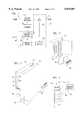
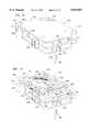
- FIG. 22illustrates a perspective view of the digitally enhanced circuit breaker of the preferred embodiment of the present invention.
- FIG. 23illustrates a perspective view of the digitally enhanced circuit breaker of the preferred embodiment of the present invention, after a protective cover has been removed to expose the control section.
- FIG. 1there is illustrated an overall block diagram of the circuit breaker of the present invention.
- a conventional standard thermal circuit breaker 10is provided having an input connected to a main terminal 12 and an output connected to a load terminal 14.
- the circuit breaker 10is what is referred to as a Ground Fault Controlled Interrupter (GFCI) circuit breaker, which has associated therewith a solenoid 16 which is designed to be activated by a control signal on a line 18, which control signal on line 18 triggers the solenoid 16, thus bypassing the thermal aspects of the circuit breaker 10 and tripping the circuit breaker 10.
- GFCIGround Fault Controlled Interrupter
- the present inventionis utilized to act as an intelligent overlay to the operation of the circuit breaker 10 and provide the control signal on the line 18 for tripping the circuit breaker 10 at an appropriate time.
- the intelligent overlayis represented by a digital processing section 20 illustrated in phantom.
- Part of the digital processing section 20is a digital control module 22, which is operable to generate the control signal on the control line 18 and receive as inputs, the voltage on the main lines 12, the voltage on the load terminal 14, and also, a current value received from a current sensor 24 disposed in series with the output of the circuit breaker 10. This therefore provides a measurement of the input voltage and output voltage of the circuit breaker 10 in addition to the current through the circuit breaker 10 on the load side of the breaker contacts (not shown).
- the digital control module 22has associated therewith a profile table 26 which is operable to contain predetermined load profiles and a current associated therewith, as will be described in more detail hereinbelow.
- a display 30is provided for displaying information about the operation of the system.
- the digital control moduleis operable to utilize the sensor inputs thereto in the form of voltage and current and effect generation of the control signal on line 18 in order to perform the trip. The criteria utilized for this tripping operation will be described in more detail hereinbelow.
- FIG. 2there is illustrated a perspective view of the circuit breaker 10 and the digital processing module 20.
- the digital processing module 20is operable to be disposed in place of the conventional tripping mechanism which is associated with the GFCI circuit breaker. In this manner, the actual internal workings of the circuit breaker 10 do not need to be modified. As such, this will provide a circuit breaker having a conventional switch 32 for resetting the circuit breaker, a conventional test button 34 for testing of the breaker 10 and a conventional thermal tripping mechanism.
- a neutral wire 38is provided, which is conventional and provides an internal reference.
- the input/output port 36allows a user to communicate with the digital control module 22 for the purposes of transmitting data thereto in the form of commands or information associated with a profile.
- FIG. 3there is illustrated a diagrammatic view of a plurality of circuit breakers disposed in a circuit breaker box 40, with a laptop computer 42 provided for interfacing a serial cable 44 to one of circuit breakers 10.
- a technicianwould analyze a given electrical situation.
- all of the circuit breakers 10could be connected through a plurality of serial cables 48 to a transmit/receive block 50, which would allow wireless or wired communication between serial control modules 22 and a remote receiver/transmitter 52.
- the type of command information that is transmitted to the breakercan be data for use in defining the operation of the breaker or, alternatively, it can be a trip command.
- One application of the digitally enhanced breaker of the present inventionis to allow a fire alarm to be connected thereto which, when activated, can result in the generation of a trip command that can be sent to and cause the breaker to automatically trip in response thereto.
- This commandcan also be a command that is sent from a municipal entity, such as the fire department or the police department. It would be advantageous for the fire department to have the ability to cause all breakers to trip automatically in the event that there were a fire. This is as opposed to trying to get to the breaker and turning it off before entering the premises. It is possible that unique ID codes could be associated with a given premises.
- FIG. 5there is illustrated a more detailed block diagram of the processing module 22.
- a central processing unit (CPU) 60which, for example, is the PIC16C73 microprocessor (CPU), manufactured by MICROCHIP, which is a controller and has associated therewith a predetermined amount of memory, as represented by block 62.
- the memory 62 in the preferred embodimentis an integral part of the CPU 60, but it could be external to facilitate larger storage capacity.
- the CPU 60has an input port that is connected to the load side of contacts 64 in the breaker 10 through a wire 66. This allows the AC voltage itself to be sensed. This is also filtered with a filter 68 to provide a second input to the CPU 60.
- the CPU 60also receives a test input connected to a test switch 70 and an input/output serial data line 72.
- a power supply 74is provided, which extracts power from the main terminal 12 and provides on the output thereof two supply levels, V 1 and V 2 , V 1 being +10.0 V and V 2 being +5.0V.
- the CPUalso interfaces with the secondary of a toroid 76, which has a single primary winding 78 disposed through the center thereof and the two ends thereof connected at two separate points along the output load line 14.
- a toroid 76which has a single primary winding 78 disposed through the center thereof and the two ends thereof connected at two separate points along the output load line 14.
- the separation of the two ends of the primary winding 78results in a predetermined amount of resistance disposed therebetween.
- the toroidal core 76does not have to be disposed about the load and take the full current therefrom. Essentially, only about 1.0 Amp maximum is passed through the primary winding 78.
- the current extracted from the secondary on the toroidal core 76is converted to a voltage with a circuit 77, which output comprises an analog voltage. This is converted to a digital value by the CPU 60.
- a thermal sensor 80 in the form of, for example, a thermistoris disposed proximate to the circuit breaker 10 to sense the temperature thereof The output of this is provided as an input to the CPU 60.
- a program select input on a line 84is provided as an input to allow a user to select a given program. In the present and preferred embodiment, this is facilitated through the use of jumpers. However, any type of input that will allow a user to select programs would be an equivalent function.
- FIG. 6there is illustrated a graph depicting appliance startup currents versus time in half-cycles.
- the inrush currentis found on the Y axis and varies from 0.0 Amps RMS to 120.0 Amps RMS. It can be seen that in the first ten half-cycles, the current can run as high as 100.0 Amps. This, of course, decreases to a level below 20 Amps, which is the circuit breaker example utilized in this graph of FIG. 6.
- a line 90representing the response of the circuit breaker to inrush current for a 20 Amp standard circuit breaker. It can be seen that a level of 180.0 Amps would require 80 half-cycles in order to trip the conventional breaker.
- a profile 92represents the response for a 1 kw lamp load, illustrating that the inrush current goes up to a very high value for a very short period of time, and then falls down below the 20 Amp level at approximately three to five half-cycles.
- a profile 94is associated with a compressor with a stiff power source, illustrating that the current goes up to a level exceeding 80 Amps and does not fall below the 20 Amp level until near 20 half-cycles.
- a profile 96is representative of a compressor with a soft power source illustrating that the initial inrush currents are slightly lower, but it requires more than 20 half-cycles to fall below the 20 Amp level.
- a vacuum cleaner profileis illustrated by a profile curve 98, which exhibits an exponential decay from an inrush current that exceeds 80 Amps to a current of less than 20 Amps after approximately 23 half-cycles.
- An air conditioner profileis represented by a profile curve 100, which rises to a level above 40 Amps and does not fall below the 20 Amp level until approximately 35 half-cycles.
- a compressor profile with a 100-foot extension footis represented by a profile curve 102, which illustrates that the initial inrush current is high, but the 100-foot extension cord results in a very soft power source and the inrush current being maintained above the 20 Amp level for over 60 half-cycles.
- a dotted line 104that illustrates the ideal curve that, if followed, would prevent tripping for all of the profiles 92-102. As long as the current versus time in half-cycles falls below this, this would represent the normal activity of the load. If it exceeds the current level represented by the profile 104, this would represent an overcurrent condition, which would not be sensed by the standard breaker, as represented by the curve 90. Therefore, by possessing the ability to recognize when current is initially applied to a load during startup of that load and determining if they exceed an ideal profile, as represented by the curve 104, a more reliable circuit breaker would result.
- short circuit currentranges from 45 Amps to 1200 Amps.
- Combustible materialcan range from tissue paper and Christmas trees to the actual wood in the 2 ⁇ 4 studs. Paper is provided in most electrical outlets, i.e., paper is utilized to cover the ground wire. Paper is also found on sheetrock and the backing on insulation. Sawdust chips are frequently found on or near most electrical outlet boxes from drilling holes in the 2 ⁇ 4 studs to run the electrical wires.
- the toroidal core 76is illustrated as having the primary winding 78 as a single wire passing through the central of the core 76 and a secondary 110, which is attached on one side to ground and on the other side to a node 112, node 112 connected to ground through a resistor 114. Therefore, a voltage will be developed on node 112 with the ratio of the toroidal core 76 being 1:1000.
- the primary wire 78is a 22 gauge wire, whereas the secondary is a much smaller gauge and has approximately a thousand turns disposed thereon, the ends of the primary winding separated by a distance of approximately 7 millimeters.
- Node 112The voltage developed on node 112 is then coupled to a node 116 through a resistor 118 and then to a node 120 through a resistor 122.
- Node 116is operable to be connected through a resistor 124 to a test terminal 126, test terminal 126 also connected to an output on the CPU 60 to receive a test pulse.
- This test pulse received on the output from test terminal 126results in a voltage disposed on node 116 representing a predetermined level of current.
- a Hall Effect devicecould be utilized in place of the toroidal core 76 to sense current flowing in the AC line.
- the node 120is connected through a resistor 128 to a node 130.
- Node 130is connected to the positive input of an amplifier 132, the negative input thereof connected to ground through a resistor 134 and to node 136.
- Node 136is connected to the negative input of amplifier 132 and also connected through a parallel connected capacitor 140 and resistor 142 to the output of amplifier 132, this representing a feedback network.
- the output of amplifier 132is connected through a resistor 144 to an input of the CPU 60.
- the node 120is connected to the negative input of amplifier 146, the positive input thereof connected to ground.
- the output of amplifier 146is connected to the base of an NPN transistor 150, the emitter thereof connected to a node 154 and the collector thereof connected to a node 152.
- Node 152is connected to the positive supply voltage V 2 at a level of +5.0V through a resistor 156 and to an input of the CPU 60 through a resistor 160.
- Node 154is connected to ground through a resistor 162 and to the anode of a diode 164, the cathode thereof connected to node 130.
- Test switch 70is connected between ground and a node 172, which node 172 is connected to a test pin and also to the +5.0V power supply through a pull-up resistor 174.
- the input 176is connected to the +5.0V power supply through a resistor 182 and the input 177 is connected to the same power supply through a resistor 184, with input 175 connected to the power supply through a resistor 181.
- the following tableillustrates the programming; however, any type of programming could be required with the internal programming of the CPU defining what profile will be selected.
- the voltage on the load side of the breakers 64 on terminal 14is connected to one side of two series-connected resistors 190 and 192, the common connection therebetween providing an input to the CPU 160. This effectively divides the voltage down such that an AC voltage can be detected for both performing a zero crossing detection operation and also for determining if the coil is present.
- the solenoid 16also has one side of the driving coil thereof connected to the load terminal 14 on the load side of the contact 64 and the other side thereof connected to a node 194. Node 194 is connected through a resistor 146 to a node 198.
- Node 198is connected to the cathode of a diode 200, the cathode thereof connected to ground, and also to the cathode of a diode 202, the anode thereof connected to a node 204.
- Node 204is connected to ground through a resistor 208, the other side thereof connected to ground.
- Node 204constitutes an input to CPU 60.
- the diodes 200 and 202provide a clamped input that prevents the input from going more than one diode drop below the ground level and will be supplied to node 204 and to resistor 206 on the positive swing of the input signal.
- solenoid 16Only when triac 212 is conductive is solenoid 16 turned on by pulling node 194 low to the potential of the neutral wire 38. Until then, node 194 will follow the voltage on the load terminal 14, this providing a voltage on the opposite side of the coil 16 to that provided by the resistors 190 and 192. Therefore, the zero crossing detect input and the node 194 can be sensed to determine if the solenoid 16 is, in fact, intact. If there is an open circuit in the solenoid 16, this will be detectable.
- the Input/Output functionis based upon an RS 232 interface requiring a series of three lines 222, a red line, a black line, and a yellow line.
- the red lineis the -12.0V input
- the black lineis the transmit input (TX)
- the yellow lineis the receive input (RX).
- the green lineis a redundant line connected to the -12.0V input.
- the transmit input on the black lineis connected to one side of an optocoupler 224, the other side thereof connected to one input of the CPU 60.
- the yellow receive input on lines 222is connected to one side of an optocoupler 226, the other side thereof connected to an output of the CPU 60. This operates in accordance with a conventional RS232 protocol.
- a Clear input MCLRis connected to one side of a three-terminal reset circuit 230, the other side thereof connected to ground and the control input thereof connected to the +5.0V input, which also constitutes the V dd input to the CPU 60.
- the circuit 230is a conventional reset circuit of the type MAX889, manufactured by MAXIM. This circuit 230 is operable to determine if there is a "brownout" condition wherein the voltage on the power supply input to the CPU 60 falls below a predetermined level. When this occurs, the circuit 230 generates a reset input and maintains this reset input at an appropriate level until the voltage comes up above an acceptable level. In this manner, it is insured that a reset will be applied to the CPU 60 when it enters an appropriate operating condition.
- the purpose of the circuit 230is specifically for this type of operation.
- a diode 232has the anode thereof connected to the main terminal 12 and the cathode thereof connected through a filter inductor 234 to a node 236.
- Node 236is connected through a resistor 238 to a node 240, node 240 having one side thereof connected to a transient suppressor 242, the other side of transient suppressor 242 connected to ground.
- An FET 244has the source/drain path thereof connected between node 240 and a node 246.
- Node 246is connected to the anode of the diode 248, the cathode thereof connected to a node 250.
- Node 236is connected through a resistor 252 to the node 254.
- Node 254is connected to the collector of an NPN transistor 258, the emitter thereof connected to ground and the base thereof connected to a node 260.
- Node 260is connected through a resistor 261 to ground and to the anode of a zener diode 262, the cathode thereof connected to a node 264, node 264 connected to node 236 with through a resistor 266.
- Node 250is connected to the anode of a diode 270, the cathode thereof connected to node 264.
- Node 250has a capacitor 272 disposed between node 250 and ground with a three-terminal regulator 274 disposed between node 250 and ground, the output terminal of the regulator 274 is for providing the +5.0V level and the node 250 providing the +10.0V level.
- diode 232provides half-wave rectification to place a half-wave rectified signal on node 236.
- currentis negligible through zener diode 262 and resistor 252, such that the gate of FET 244 is pulled high, causing FET 244 to conduct and charge capacitor 272 through diode 248.
- zener diode 262will conduct and turn transistor 258 on.
- transistor 258turns on, FET 244 is turned off, such that FET 244 will not conduct while the AC voltage is greater than about 30 to 40 volts.
- the transistor 258will turn off and FET 244 will again turn on, such that current is provided twice during each positive half-cycle.
- Thisimproves efficiency and allows the use of a smaller filter capacitor.
- Regulationis improved by the diode 270 which conducts when the output voltage is greater than a diode drop above the zener voltage of diode 262.
- This diode 270makes the value of resistor 261 less critical and also makes the output voltage less sensitive to load current.
- the diode 256utilizes the V EBO of the transistor as a 7-Volt zener diode to clamp the gate-source voltage of the FET 244, since that should not exceed approximately 20 Volts.
- a capacitor 259is connected across the collector/emitter of transistor 258 to slow the rate of rise of the voltage of the collector thereof, such that when the power is applied at the peak of the AC cycle, the gate voltage of FET 244 rises at a controlled rate, thus allowing the transistor 258 time to detect and clamp the overvoltage condition.
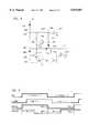
- FIG. 9there are illustrated waveforms for calculating phase by simulating a synchronous detector.
- the sign inputwhich is extracted from node 152 in response to transistor 150 being turned on or off, is determined on the curve I -- LINE, with the tapped voltage on the common point between resistors 190 and 192 utilized to generate the waveform VAC. It can be seen that when the signal VAC goes high, this indicates that the zero crossing has gone from a negative to a positive and the value is equal to "1".
- the currenton the other hand, will change sign when it goes from a negative to a positive and the sign will go to a value of "1". This occurs at the zero crossing of the current waveform.
- the difference between these two waveformsconstitutes the phase angle.
- the phase algorithmdetermines a cosine term, COSVAR, and a sine term, SINVAR.
- the cosine termis calculated by first determining if the zero crossing value is high, i.e., whether the signal VAC is high. If it is high, then the output of the analog-to-digital conversion operation (ADC) of the detected current from the output of resistor 144 is summed with the previous cosine term. If the zero crossing value is "0", i.e., the VAC is low, then the output of the ADC operation is subtracted from the accumulated cosine term. For the sine term, the sample count is shifted by a value of "8", there being a total of sixteen samples for each half cycle of the AC signal.
- ADCanalog-to-digital conversion operation
- the accumulated sine valueis incremented by the output of the ADC operation and, if it is less than 8, it is decreased.
- the sample countis initiated when the zero crossing is detected and terminated at the next zero crossing for a negative value, wherein the zero crossing is equal to "1", if the line voltage is greater than 0 and "0" if it is less than 0.
- the accumulated cosine sum and the accumulated sine sumare proportional to the cosine and sine of the phase angle between the line voltage and current. Their ratio will be the tangent of the phase angle. Since the tangent increases monotonically, it can be utilized directly in the decision-making operation. Whenever the sample count is greater than 14, then the tangent of the phase angle is calculated.
- the program for the phase angle determinationis as follows:
- a power-up trip curveprofile
- theseare predetermined curves that define the trip current as a function of time to account for various input inrush currents and load conditions.
- the power-up trip curveis selected upon power up of the system, i.e., when the CPU 60 is reset or brought into operation. This is basically a default power-up trip curve or profile. This profile is selected for a predetermined duration of time to ensure that all self-test operations, etc., have been performed. Thereafter, the user-defined profile is used, which is referred to as a "running" profile.
- the programflows to a function block 302 wherein the microprocessor is initialized. This is a conventional operation with a microprocessor.
- the programthen flows to a function block 304 to perform a self-test operation.
- the self-test operationis an operation which includes in part the generation of a test pulse on the line 126 which raises the node 116 high through resistor 124, with reference to FIG. 7. This places a predetermined voltage on node 120, turning off amplifier 146 and turning on amplifier 132 to a predetermined level.
- This analog valueis then converted to a digital value through the internal analog-to-digital conversion in the CPU 60 and then compared to an expected value. If the measured value is within acceptable limits of the expected value, then the test is successful. Additionally, the voltage on both sides of the solenoid 16 is tested to determine if the solenoid is present, i.e., the driving coil therein conducts. The gate voltage to the triac 212 is also tested for a short period of time which time is insufficient to actually turn on the triac 212.
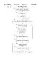
- the programwill flow to a decision block 306 to wait for a zero crossing. Until the zero crossing occurs, the program will flow back around a "N" path to the input thereof. When the zero crossing occurs, the program will flow along a "Y" path to a function block 308 to transfer serial data through the I/O port, if data is to be transmitted. The program will then flow to a function block 310 to then perform a reading of the detected current after conversion to a digital value. This is effectively a "sample”. The program will then flow to a function block 312 to determine the phase angle and then to a function block 314 to accumulate the current data.
- the programthen flows to a function block 316 to determine if a trip condition exists and then flows to a function block 318 to read the AC voltage.
- the programthen flows to a function block 320 to increment the sample count and then to a decision block 322 to determine if the sample count is the maximum sample count of 16. Until the sample count has reached its maximum, the program will flow back to the function block 308 to again send RS 232 data. When it reaches the maximum count, the program will flow along the "Y" path back to the input of decision block 306 to wait for the next zero crossing. This therefore insures that only 16 samples are taken for each half cycle.
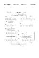
- the programis initiated at a decision block 324 to determine whether the main part of the breaker has tripped for any reason. If so, the program flows along a "Y" path and, if not, the program flows along a "N" path. When the breaker is not tripped, the program flows to a decision block 326 along the "N" path, decision block 326 determining whether there is any arcing. This is determined in accordance with a predetermined algorithm, which will be described hereinbelow. If arcing is present, the program flows along a "Y" path to a function block 328 to trip the breaker and then to a return block 330.
- the programwill flow to a function block 334 to set the loop count value equal to "10", and then the program will flow to a function block 336 to set an internal timer to a value of "0". The program then flows to a decision block 338 to determine if the zero crossing has occurred. If not, the program flows along an "N" path to a decision block 340 to determine if the timer has incremented to a value of 1 msec. If not, the program will loop back to decision block 338.
- the programWhen the timer has timed out to 1 msec, the program will flow along a "Y" path to a function block 342 to decrement the loop counter and then to a decision block 344 to determine if the loop count is equal to "0". If not, the program flows back to the input of function block 336 and, if so, the program flows along the "Y" path to a function block 346 to set the Tripped Flag to a true value. The program then flows to a function block 348 to set a timer value equal to "0". If the zero crossing had been detected at decision block 338, the program will flow along a "Y" path to the function block 348 to also set the timer equal to a "0" value.
- the programAfter the time has been set to a "0" value at function block 348, the program will flow to a function block 350 to set the sample count equal to "0". The program will then flow to a function block 352 in order to read the data input on the serial data port, if data is there. The program will then flow to a decision block 354 to determine if a manual reset has been performed, i.e., the lever is manually moved to the "ON" position. The program with either flow along a "Y” path or an "N" path.
- FIG. 12there is illustrated a continuation of the flowchart of FIG. 11. If a manual reset has been performed, the program will flow to a function block 356 to initialize the system and then to a function block 358 to again perform the self-test. The program will then flow to a function block 360 to check the manual test switch. This function block 360 is also where the "N" path from decision block 354 flows. The program then flows to a function block 362 wherein a two-second timer is incremented, which two-second timer is a continuous cycling timer. The program then flows to a decision block 364 to determine if the value of a two-second timer is equal to "0".
- the function block 368 for calculating the soak currentcalculates the long term running average value for the current that represents current history.
- the programflows to a function block 370, which increments the self-test timer.
- the programthen flows to a decision block 372 to determine if the self-test timer is at a "0" value. If so, the program flows along a "Y" path to a function block 374 to perform the self-test and, if not, the program flows along an "N" path to a function block 376 to turn on the LED, which is also the path that is followed after the function block 374.
- the output of the function block 376goes to decision block 366 to determine if the 65 msec timer is true.
- the programwill flow from decision block 366 along the "Y" path thereof to function block 378 to turn off the LED and then to a return block 380, this 65 msec time being the time the LED is OFF for a blinking display condition. If the 65 msec timer is not true, i.e., it has not timed out, the program will flow along an "N" path to the return block 380.
- the flowcharts of FIG. 11 and 12initially will test for a zero crossing by looping through a sub-routine for a period of 10 msec. If the zero crossing has not been detected in 10 passes through the loop blocks 338-344, then a trip flag will be set equal to true, this indicating a trip condition.
- the timer valueis set for "0" and the sample count value is set to "0". Thereafter, each 2 seconds the soak current is calculated and then the self-test timer incremented. After a predetermined number of 2 second increments, the self-test timer times out and then the self-test is performed.
- the LEDis turned on (if data indicates that it should be) to indicate problems that may exist as a result of the self-test and this LED is maintained on for a period of 65 msec, after which it is turned off. If the self-test is not again done on the next pass, the LED will again be turned on in the path between decision block 372 and function block 376 to result in a flashing LED.
- FIG. 13ais directed toward the Send operation and is initiated at a decision block 384 that determines if the sample count is equal to "0". If so, the program will flow along a "Y" path to a function block 386 to place a data byte in the output buffer. Since the sample count is equal to "0", this indicates a zero crossing. The program will then flow to a function block 388 to set the Start bit equal to "1" and then flow to a Return block 390.
- the programwill flow along the "N" path to a function block 392 wherein the data will be shifted to the right by a value of "1". The program will then flow to a function block 394 to set the Output bit to either a "high” or “low” value, and then the program flows to the return block 390.
- the Read operationis initiated at a function block 396, wherein the received data bit is shifted to the right by a value of "1".
- the programthen flows to a function block 398 to read the next data bit and then to a decision block 400 to determine if the data is set to a remote trip. If so, the program will flow along a "Y" path to a function block 402 wherein the breaker will be tripped in response to receiving this data and then flows to a return block 404.
- Thisis a function wherein an external or remote location can transmit to the breaker a tripped signal which will force the trip to occur.
- the programwill flow along a "N" path to a decision block 406 to determine if the self-test operation has been defined by the data. If so, the program will flow along a "Y" path to a function block 408 to perform the self-test and then to the return block 404. If the self-test command has not been received, the program will flow along a "N" path to a decision block 410 to determine if a reset command has been received. If so, the program will flow along a "Y" path to a function block 412 to initialize the data registers and then to the return block 404. If the reset operation has not been indicated by the received data, the program will flow along a "N" path to the return block 404.
- Trip FlagWith respect to a Trip operation, this is initiated by the Trip Flag being set to a true condition.
- the firstis to immediately trip the breaker by turning on the triac 222.
- the secondis to trip the breaker only at a zero crossing detection. The latter method will prevent current arcing at the contacts.
- the methodis selectable by the user either through uploading of a command or by incorporating an external jumper.
- FIG. 14there is illustrated a flowchart depicting the ADC conversion routine, which is initiated at a function block 418 to initiate the ADC conversion, and then the program flows to a decision block 420 to determine if the conversion is complete. If not complete, the program will loop back to function block 418. When complete, the program flows along the "Y" path to a function block 422 to set the polarity flag at either a"+" or a"-".
- the analog value output by the amplifier 132is input directly to the CPU 60, which input pin associated therewith is programmed as an analog input. This will result in an eight-bit digital value being generated with an internal analog-to-digital converter.
- the sign of the signalcan occupy a 9th bit. Therefore, a 9 bit analog-to-digital converter is realized.
- the programwill flow to a function block 424 to determine if the level of the ADC is greater than the immediate trip level.
- the immediate trip levelis a level that indicates instantaneous excessive current. If so, the program will flow along the "Y" path to a function block 426 to trip the breaker and then to a return block 428. However, if the immediate trip level has not been exceeded, the program will flow along an "N" path to a decision block 430 to determine if the ADC value is greater than the global peak value which was previously stored. If so, the program will flow along a "Y" path to a function block 432 to set the global peak value in the associated register to the current ADC value. The program will then flow from function block 432 to a function block 434, which is also the path that the decision block 430 will make along the "N" path thereof if the ADC value is determined to be less than or equal to the global peak value previously stored.
- the decision block 434determines if the ADC value is greater than the previously stored cycle peak value.
- the cycle peak valueis the peak value for that given cycle. If not, the program will flow along the "N" path to return block 428. If so, the program will flow along the "Y" path to a function block 436 to set the cycle peak current register to the current ADC value. The program will then flow from function block 436 to the return block 428.
- FIG. 15there is illustrated a flowchart depicting an operation wherein the current data will be accumulated.
- This programis initiated at a decision block 438 which will compare the present ADC value to the accumulated value. If it is equal to the accumulated value, the program will flow to a return block 440. If the ADC value is greater than the previous accumulated value, the program will flow to a function block 442 to set the sign equal to a value of "+1". If the ADC value is less than the accumulated value, the program will flow to a function block 444 to set the sign value equal to "-1". The function blocks 442 and 444 will then both flow to a function block 446 to fetch an input rate table index and then flow to a function block 448 to obtain a charge rate. The current accumulator will then be updated, as indicated by a function block 450 and then the program will flow to a return block 452.
- the accumulation operationis a method for increasing or decreasing an accumulator value by a predetermined rate, depending upon whether the present value of the current is above the previous accumulated value or below the accumulated value.
- the rate valueis provided such that a sharp increase in current between two samples will not replace the previous accumulated value with the present value of the current but, rather, will increase it by a predetermined factor.
- Thisin a sense, is a digital filter that is analogous to a software RC circuit. This digital filter will effectively smooth out any transients that are due to high current peaks and such. Therefore, instantaneous transients that do not result in a great deal of energy placed into the load or through the breaker will not cause the breaker to trip.
- FIG. 16there is illustrated a flowchart depicting the self-test operation, which is initiated at a decision block 454 that determines whether the minimum current reading is less than 50 amps. If not, the program will flow along a "N" path to a function block 455 indicating that the minimum current reading has failed and then to a function block 453 to set the red LED to an on condition and then to a return block 457. However, if the minimum current reading is less than 50 amps, the program will flow along a "Y" path to the decision block 454 to a function block 456 to generate the test pulse for a current equivalent to approximately 120 amps.
- the programwill then flow to a function block 458 to read the current ADC value and then to a decision block 460 to determine if the ADC value is greater than 100 amps. If not, this indicates a failure and the program will flow to a function block 462 indicating a maximum current reading failure and then to the function block 453 to set the red LED to an on condition. However, if the 100 amp test has been passed, i.e., the current was read to be greater than 100 amps, the program will flow along the "Y" path to a function block 464 to set the test pulse equal to "0", i.e., take it low.
- the programwill then flow to a function block 466 to set the trigger signal high, which trigger signal is the gate control signal for the triac 212 and then flows to a decision block 468 to determine if the trigger signal is high. If not, the program will flow to a function block 470 to indicate a failure of the trigger signal and then to the function block 453 to set the red LED to an on condition. If the trigger signal is indicated as being high, the program will flow from decision block 468 along the "Y" path thereof to a function block 472 in order to again set the trigger signal to a low condition.
- the time between the trigger signal going high and the trigger signal going lowis a very small amount of time which will not raise the node 214 high, due to the fact that the capacitor 220 cannot charge up through resistor 216. Therefore, the triac 212 will not be turned on. The program will then flow from function block 472 to the return block 457.
- FIG. 17there is illustrated a flowchart depicting the manual test operation, which is initiated at a function block 474 to turn the red LED on and then to a function block 476 to perform a self-test.
- the programthen flows to a function block 478 to wait for 262 msec, after which time the red LED is turned off, as indicated by a function block 480.
- the programthen flows to a function block 482 to start the two-second timer and then to a decision block 530 to determine if the manual test switch has been pressed. If it has not been pressed, the program will flow along a "N" path to a return block 532.
- the programwill flow along the "Y" path to a decision block 534 to determine if the two-second timer is equal to "0". If not, the program will loop back around the "N" path to decision block 530. When it has timed out, the program will flow along the "Y” path to a function block 536 to trip the breaker and then to the return block 532.
- FIG. 18there is illustrated a flowchart depicting the operation for reading the AC voltage, which is initiated at a function block 538 wherein the two voltage inputs, which are multiplexed, are selected such that channel 1 constitutes the node 204 that measures the voltage on node 194 on the opposite side of the solenoid 16 from the load terminal 14.
- the programwill then flow to a function block 540 to initiate the conversion and then to a decision block 542 to determine if the conversion is complete. If not complete, it loops back upon itself and, if complete, the program flows to a function block 544 to determine if the breaker is tripped. If not tripped, the program flows along a "N" path to a function block 546 to save the ADC reading. The program then flows to a function block 548 to select the other voltage input. If the breaker is tripped, the program will flow along a "Y" path from decision block 544 to function block 548.
- the channel 1 operationperforms a conversion, as noted above with respect to block 540 and 542, and then flows to a function block 550 to determine if the AC voltage is greater than the maximum voltage limit MAX -- VLIMIT. If so, the program will flow along a "Y" path to a function block 552 to trip the breaker and then to a return block 554. If the AC voltage does not exceed the maximum voltage, the program will flow along the "N" path from decision block 550 to a decision block 556 to determine if the AC voltage is less than the minimum voltage limit MIN -- VLIMIT. If the AC voltage is greater than the minimum voltage limit, the program will flow along a "N" path to the return block 554.
- the programwill flow along a "Y" path to a decision block 558 to determine if the current is greater than a predetermined current limit. If not, the program will flow along a "N" path to the return block 554. If the current does exceed the predetermined current limit, the program will flow along a "Y" path from decision block 558 to the function block 552 in order to trip the breaker.
- Arc generationis, in general, an intermittent operation wherein current is momentarily interrupted for either one half of a cycle or multiple cycles. This interruption can be in the form of a total interruption of current or a momentary decrease in current due to the resistive nature of the discontinuity in the wire.
- the technique for detecting the arc in the present inventionis to sample the peak current during the positive half of the cycle and sample the peak current during the negative half of each cycle. For each cycle, the positive peak current and the absolute value of the negative current are added together and divided by two to provide the average thereof. This average is compared with the average of the previous cycle and the difference therebetween compared to a threshold.
- this differenceexceeds the threshold, this constitutes an arc.
- the differencesare accumulated for a number of cycles and, if the differences have accumulated to a value that exceeds a predetermined threshold, then an arc is declared to be present. Of course, after a predetermined period of time, this will be reset and the sequence initiated again.
- the operationis initiated at a decision block 584 to determine if the peak current term for a given half of a cycle IPKCYCLE is greater than or equal to the first limit. If yes, the program proceeds to a function block 585 and, if no, the program flows to a function block 586.
- Function block 585sets a value of "K" to the peak cycle value divided by the factor "N1”, and the function block 586 sets the value of K equal to the value of the peak cycle.
- the programthen flows to a function block 587 to set the average value equal to the value of K plus the previous peak value.
- the programthen flows to a function block 588 to set the previous peak value set to the value of K.
- the programthen flows to a function block 589 to determine if the AC voltage is greater than zero. If not, the program flows to return block 590 and, if so, the program flows to a function block 591.
- Function block 591sets a DELTA value equal to the average value AVG minus the average arc value ARC -- AVG.
- the programthen flows to a decision block 592 to determine if the sign of the value of DELTA has changed. If so, the program then flows along a "Y" path to a decision block 594 and, if not, the program flows along an "N" path to a function block 596. At decision block 594, a determination is made as to whether the value of DELTA is greater than a minimum DELTAMIN.
- the programflows along a "Y" path to a function block 598 to set an accumulator value ACC equal to the value of DELTA plus the previous accumulator value.
- the programthen flows to a decision block 599, this being the path from function block 594 along the "N" path thereof.
- Decision block 599determines whether the accumulator value is greater than a predetermined threshold value. If so, the program will flow to a function block 600 along the "Y" path thereof to declare an arc and then to function block 596. If the accumulated value is not greater than the threshold, the program would flow from decision block 599 along the "N" path thereof to the function block 596.
- the programwould flow to the function block 596 to set the ARC -- AVG value equal to the AVG value.
- the programthen flows to a function block 602 to decrement the accumulator value and then to a return block 603.
- the function blocks 585 and 586basically determine if the current has exceeded a limit and, if so, function block 585 will provide an attenuation factor thereto.
- the function block 587determines the average as the average current of the last negative peak and the immediately preceding positive peak.
- the function block 589determines whether the AC voltage is greater than zero, which operation is performed typically on positive peaks and low-to-moderate currents.
- the path of decision block 594 and function block 598is the accumulation operation wherein the DELTA value between two successive cycles is determined to be greater than a predetermined minimum and, if so, this is added to an accumulator value.
- the function block 602is a decrement function that prevents the accumulator from continuing to grow in value. If there are no arcs present, the value in the accumulator will slowly decline.
- the program associated with the flowchart of FIG. 19is as follows:
- FIG. 20there is illustrated a flowchart depicting the operation wherein the system can operate in an adaptive manner to update the profile.
- the programis initiated at a function block 505 and then to detect a transient. In general, whenever a steady load is present, this will not cause the system to trip. However, when a transient occurs due to a change in load as a result of either turning an appliance on or varying the load of an appliance, this will result in a transient. This is detected and then the program will flow to a function block 506 to store the local profile without this transient.
- the local profilebasically defines a current versus time profile about the transient.
- the programwill then flow to a decision block 508 to determine if a trip has been declared by the circuit as a result of the current due to the transient exceeding the current in the pre-stored profile which is referred to as a "running" profile. If the trip operation has occurred as a result of the current exceeding that defined by the running profile, the program will flow to a decision block 510 to determine if an update operation should be performed.
- An update operationis a procedure which can be manually or remotely initiated and is a result of a user determining that the trip was improper, i.e., the load was operating in an expected manner and the trip was in error.
- the programwill flow along a "Y" path to a function block 512 wherein the stored profile about the transient will be modified by incrementing the current value by, for example, 10% over the appropriate time frame.
- This new modified profilewill then replace the running profile, as indicated by a function block 514.
- This replacement with the modified profileprovides an adaptive system which, although not shown, could be automated wherein a known load is placed on the system with the actual trip operation being prevented until the modified profile has been stored. For each trip indication, but not actual trip, a modified profile is generated and stored. This will continue until subsequent transients result in no generation of a trip. Thereafter, the system can be placed in a "run” mode, wherein a transient exceeding the running profile will cause an actual trip.
- An alternative methodis to utilize an external system for generating the profile and then downloading the generated profile into memory in CPU 60.
- FIG. 21there is illustrated a flowchart depicting the operation of the Check Phase block 312 of FIG. 10.
- This routinedetermines the sine and cosine of the fundamental Fourier component of the load current. This includes both amplitude and phase information.
- the programis initiated at a function block 518 to set the value of "I" to the sample count.
- the programthen flows to a decision block 520 to determine if the value of "I" is equal to zero and the AC voltage is positive. If not, the program flows to a function block 522 in order to set the value of SINVAR and COSVAR to zero at the zero crossing of the positive going portion of the cycle. If not, the program will flow to a decision block 524, the function block 522 also flowing to the decision block 524.
- the decision block 524determines whether the AC voltage is greater than zero. If so, the program flows to function block 526 to set the sign value to "+1" and if not, the program flows along an "N" path to function block 528 to set the sign value to "-1". The function blocks 526 and 528 will then flow to a function block 530 to calculate the following equation:
- the programthen flows from function block 530 to a function block 532 in order to determine if the value of "1" is greater than one-half the maximum count. At present, the maximum count is set to fifteen, but it might be larger in future embodiments. If so, the program flows along the "Y" path to a function block 534 to invert the sign value and, if not, the program flows directly to a function block 536. Function block 534 also flows to function block 536.
- the equation in function block 536is as follows:
- the programthen flows from function block 532 to a function block 538 to determine if the value of "I" is equal to the maximum count and the AC voltage is negative. If not, the program will flow to a return block 540 to return to function block 314. If so, the program will flow from function block 542 to determine if the phase angle is greater than a first phase angle limit. If so, the program will flow along a "Y" path to a function block 544 to select a profile "P1", and then to the return block 540. However, if the phase is not greater than the first phase angle limit, the program will flow to a decision block 546 to determine if the phase angle is greater than a second phase angle limit.
- the circuit breaker 610includes a lower half 612 which provides a standard type of contact section and an upper half 614 which provides a control section.
- a housing 616is provided by a plastic case which encloses the contact section 612 and the control section 614 of the circuit breaker 610.
- the housing 616has a notch 618 by which the circuit breaker. 610 is secured within a power panel.
- the circuit breaker 610includes a single throw and reset switch lever 620 which is used to push the primary power contacts of the circuit breaker 610 together and to reset the circuit breaker 610 after it has been tripped.
- a test button 624is also provided for testing operation of circuit breaker 610.
- a clip-on electrical connector 626is provided for connecting the circuit breaker 610 onto a power bus of a power panel within which circuit breaker 610 is installed.
- a terminal connector 628is provided for connecting an output power conductor to the circuit breaker 610.
- the terminal connector 628is preferably of the type having a tightening screw to secure the output power conductor therein. However, the breaker does not have to have a tightening screw. Some breakers are designed to be used with solid wire that pushes into a contact receptacle.
- a tightening port 632is provided to allow access to turn the tightening screw for securing a power conductor to the terminal connector 628.
- the output power conductorwill pass through an open end 630 of the housing 616.
- the circuit breaker 610further includes a neutral lead wire 634 which passes through a port 636.
- the circuit breaker 610also includes a serial I/O port 642.
- the serial I/O port 642includes a 4-conductor wire assembly 640 and a female connector 642.
- the 4-pin female connector 642is preferably of the type commonly used for telephone handset connectors. Screw fasteners 646 are provided for securing the components of the housing 616 around the contact section 612 and the control section 614 of the circuit breaker 610.
- the control section 614includes a circuit board 652. It should be noted that the circuit board 652 is mounted within the standard housing 616 of a standard type ground fault circuit breaker, which has been modified to accept the circuit board 652.
- the circuit board 652includes a CPU 654 which provides microprocessor control of the circuit breaker 610.
- Four terminals 656are provided on the circuit board 652 for mounting the terminal ends of the four conductor wires of assembly 640 of the serial I/O port 642 to the circuit board 652.
- a lead wire 658is soldered between the clip-on connector 626 and the circuit board 652.
- a lead wire 660extends between and electrically connects the circuit board 652 to the terminal connector 628.
- a bus bar 662is mounted within the housing 616, connected in series between the power output of the contact section 612 and the terminal connector 628.
- the electrical current passing through the circuit breaker 610is passed directly through the bus bar 662 in passing from the contact section 612 to the terminal connector 628.
- One end of the bus bar 662is electrically connected to the contact section 612 by a first lead wire (not shown) and the other end is connected to the terminal connector 628 by a second lead wire (not shown).
- a lead wire 664has two terminal ends which are soldered to the bus bar 652, preferably spaced seven (7) millimeters.
- the lead wire 664provides a single loop for passing through a toroidal coil 666.
- the toroidal coil 666preferably has one thousand (1,000) turnings.
- Opposite terminal ends of the toroidal coil 666are connected to the circuit board 652 by two lead wires (not shown).
- the output from the toroidal coil 666is connected to the circuit board 652 for sensing the current passing through the bus bar 652 and the circuit breaker 610.
- a solenoid 668is mounted to the circuit board 652 and is selectively activated to move a lever 670 to trip the circuit breaker 610 when a fault is detected by the CPU 654. Activation of the solenoid 668 will move the lever 670 toward the bus bar 662, which will trip the circuit breaker 610 to open the power contacts of contact section 612.
- a test contact 672 and a test contact 674are both mounted to the circuit board 652, and have ends which are spaced apart and extend in parallel. Pressing the test button 624 into the housing 616 will push the contact 672 into the contact 674, making an electrical connection therebetween and causing a self-test cycle to be initiated.
Landscapes
- Emergency Protection Circuit Devices (AREA)
Abstract
Description
TABLE 1______________________________________Typical Residential Circuit Breaker Trip Times vs Constant Overload% Of BreakerCircuit BreakerRating 20Amp Rating 30 Amp Rating Trip Time______________________________________100% 20Amps 30 Amps NoTrip 200% 40Amps 60Amps 50Sec 300% 60Amps 90Amps 12 Sec500% 100Amps 150 Amps 3 Sec1,000% 200Amps 300 Amps 0.62 Sec5,000% 1,000 Amps 1,500 Amps 0.01 Sec______________________________________
TABLE II______________________________________J1 J2 J3 RESULT______________________________________GND GND GND --GND GND +V Std, No ArcGND +V GND FastGND +V +V Std+V GND GND --+V GND +V --+V +V GND --+V +V +V --______________________________________
__________________________________________________________________________PHASE ALGORITHM:__________________________________________________________________________Do.sub.-- phase( )if ((sample.sub.-- cnt==0) && (AC.sub.-- VOLTAGE==1)) { cosH=cosL=0 ; // Clear accumulators at beginning of full cycle. sinH=sinL=0 ; // COSVAR=cosH*256+cosL, SINVAR=sinH*256+sinL. }if (ac.sub.-- voltage == 1) sign= 1 ;// For the COSVARaccumulation. else sign = -1 ;COSVAR = COSVAR+sign*ADRES*sin.sub.-- table(I) ; value proportional tosin(phase)if (sample.sub.-- cnt>= (MAX.sub.-- I/2)) sign =|sign ;// For the SINVAR accumulation.SINVAR = SINVAR+sign*ADRES*cos.sub.-- table(I) ; value proportional tocos(phase)// Phase calculation is complete when sample.sub.-- cnt=MAX.sub.-- I and AC.sub.-- VOLTAGE=0.// That is, at the end of a negative half-cycle.if (sample.sub.-- cnt==MAX.sub.-- I) // Select trip profile base onphase. Select.sub.-- profile ( );}____________________________________________________________________________________________________________________________________________________ARC DETECTION ALGORITHM:__________________________________________________________________________Check.sub.-- ARC( ){ //10byte avg, delta.sub.-- i, k; // temporary local variables.IF(IPKCYCLE>= 16) k = IPKCYCLE/4 + 12;else k = IPKCYCLE;avg = k + IPREVPK; // present average current of the last positive // peak and the negative peak before that.IPREVPK = k; // save the present peak value.if( VOLTS.sub.-- AC > 0) // do this only on positive peaks // (60 time per second).{ //20 delta.sub.-- i = avg - ARC.sub.-- AVG; // is new average significantly different // from the previous average and is the // sign different? if(( delta.sub.-- i>0) && (LAST.sub.-- SIGN==0)∥ // positive now, was negative (delta.sub.-- i<0) && (LAST.sub.-- SIGN==1)) // negative now, was positive { //30 // then signs are different. delta.sub.-- i = abs(delta.sub.-- i); // make delta.sub.-- i positive so we can add it // to the ARC.sub.-- ACCUM. if(delta.sub.-- i>ARC.sub.-- MIN) // is the difference significant? { //40LAST SIGN = |LAST.sub.-- SIGN; // complement the sign flag.if(delta.sub.-- i<8)delta.sub.-- i = 8; // 8 amps minARC.sub.-- ACCUM = ARC.sub.-- ACCUM + delta.sub.-- i; // this looks like an arc.if(ARC.sub.-- ACCUM>255)&&((MODE & 0x04)|=x04) Do.sub.-- trip; // trip the breaker on overflow.} //40} //30ARC.sub.-- AVG = avg; // update the average current.if (ARC.sub.-- ACCUM> MAX.sub.-- ARC)MAX.sub.-- ARC = ARC.sub.-- ACCUM: // Max during the logging // interval.if (ARC.sub.-- ACCUM > 0)ARC.sub.-- ACCUM = ARC.sub.-- ACCUM-1; // decrement the arc accumulator // on every whole cycle (60× per second)} //20} //10 end__________________________________________________________________________COSVAR=COSVAR+S*sin(i)*ADC
SINVAR=SINVAR+S*cos(i)*ADC
Claims (45)
Priority Applications (1)
| Application Number | Priority Date | Filing Date | Title |
|---|---|---|---|
| US08/695,076US5875087A (en) | 1996-08-08 | 1996-08-08 | Circuit breaker with integrated control features |
Applications Claiming Priority (1)
| Application Number | Priority Date | Filing Date | Title |
|---|---|---|---|
| US08/695,076US5875087A (en) | 1996-08-08 | 1996-08-08 | Circuit breaker with integrated control features |
Publications (1)
| Publication Number | Publication Date |
|---|---|
| US5875087Atrue US5875087A (en) | 1999-02-23 |
Family
ID=24791462
Family Applications (1)
| Application Number | Title | Priority Date | Filing Date |
|---|---|---|---|
| US08/695,076Expired - LifetimeUS5875087A (en) | 1996-08-08 | 1996-08-08 | Circuit breaker with integrated control features |
Country Status (1)
| Country | Link |
|---|---|
| US (1) | US5875087A (en) |
Cited By (105)
| Publication number | Priority date | Publication date | Assignee | Title |
|---|---|---|---|---|
| US5982596A (en)* | 1998-05-05 | 1999-11-09 | George Authur Spencer | Load center monitor and digitally enhanced circuit breaker system for monitoring electrical power lines |
| US6031749A (en)* | 1999-03-31 | 2000-02-29 | Vari-Lite, Inc. | Universal power module |
| US6049143A (en)* | 1998-08-26 | 2000-04-11 | Ofi, Inc. | Electrical connection safety apparatus and method |
| US6141202A (en)* | 1998-08-07 | 2000-10-31 | Daimlerchrysler Ag | Method and apparatus for triggering a fuse |
| US6195243B1 (en)* | 1998-05-05 | 2001-02-27 | George Auther Spencer | Method and apparatus for adaptive configuration and control in a network of electronic circuit breakers |
| US6233128B1 (en)* | 1999-03-29 | 2001-05-15 | George A. Spencer | Data retention in a circuit breaker |
| US6278254B1 (en)* | 1999-03-11 | 2001-08-21 | Richard D. Harkey | Programmable and interactive motor starter |
| US6335852B1 (en)* | 1996-12-20 | 2002-01-01 | James Nimmo | Programmable fuse and programming device for timer |
| US6356426B1 (en)* | 1999-07-19 | 2002-03-12 | General Electric Company | Residential circuit breaker with selectable current setting, load control and power line carrier signaling |
| US6377427B1 (en) | 1995-03-13 | 2002-04-23 | Square D Company | Arc fault protected electrical receptacle |
| WO2002033720A1 (en)* | 2000-10-16 | 2002-04-25 | Leviton Manufacturing Co., Inc. | Circuit interrupting device |
| US20020071228A1 (en)* | 1998-08-24 | 2002-06-13 | Steve Campolo | Circuit interrupting device with reset lockout and reverse wiring protection and method of manufacture |
| US20020101695A1 (en)* | 2001-01-26 | 2002-08-01 | Saksa Thomas A. | Adaptive power circuit protection apparatus and method |
| US6433555B1 (en) | 1999-02-17 | 2002-08-13 | Eagle Electric Manufacturing Co., Inc. | Electrical circuit interrupter |
| US6456471B1 (en)* | 1998-02-19 | 2002-09-24 | Square D Company | Test, reset and communications operations in an ARC fault circuit interrupter with optional memory and/or backup power |
| US6466029B2 (en) | 2000-04-04 | 2002-10-15 | Contact Technology Systems, Inc. | Power line testing device with signal generator and signal detector |
| EP1046971A3 (en)* | 1999-04-19 | 2003-01-15 | Phoenix Contact GmbH & Co. KG | Electronic control device |
| US6515564B2 (en) | 1999-02-17 | 2003-02-04 | Eagle Electric Manufacturing Co., Inc. | Electric circuit interrupter |
| US6525541B1 (en) | 1999-11-24 | 2003-02-25 | Eagle Electric Manufacturing Co., Inc. | Electric circuit interrupter with fail safe mode and method |
| US6556405B2 (en)* | 2000-01-20 | 2003-04-29 | Hitachi, Ltd. | Programmable controller |
| US20030086219A1 (en)* | 2001-03-21 | 2003-05-08 | Richard Bernstein | GFCI reset lockout |
| US6563685B2 (en)* | 1999-12-06 | 2003-05-13 | Schneider Electric Industries Sa | Thermal protection relay |
| US6577963B1 (en)* | 2000-12-12 | 2003-06-10 | International Business Machines Corp. | Programmatic resetting of circuit breakers |
| US20030156369A1 (en)* | 2002-02-12 | 2003-08-21 | Abb Schweiz Ag | Reception of protection commands in a remote tripping device |
| US6617858B1 (en)* | 1998-05-07 | 2003-09-09 | Siemens Aktiengesellschaft | Method and circuit for measuring a current |
| US20030174457A1 (en)* | 2000-06-16 | 2003-09-18 | Reinhard Herbst | Method for operating an electromagnetic switching device and electromagnetic switching device |
| US6646430B1 (en) | 1998-06-30 | 2003-11-11 | Delta Electrical Limited | Current measuring shunt with circuitry mounted thereon |
| US6671150B2 (en) | 2001-11-07 | 2003-12-30 | Eaton Corporation | Circuit breaker for detecting an excessive voltage and tripping responsive thereto |
| US20040004795A1 (en)* | 2001-03-20 | 2004-01-08 | Chan David Y. | Neutral switch test mechanism for a circuit interrupter |
| US20040090722A1 (en)* | 2001-03-21 | 2004-05-13 | Ulrich Richard J. | Alci with reset lockout and independent trip |
| US20040095696A1 (en)* | 1998-08-24 | 2004-05-20 | Ziegler William R. | Circuit interrupting system with independent trip and reset lockout |
| US20040108923A1 (en)* | 1998-08-24 | 2004-06-10 | Disalvo Nicholas L. | Reset lockout for circuit interrupting device |
| US20040160295A1 (en)* | 1998-08-24 | 2004-08-19 | Disalvo Nicholas L. | IDCI with reset lockout and independent trip |
| US6791315B2 (en) | 2000-01-06 | 2004-09-14 | Delta Electrical Limited | Current detector and current measuring apparatus including such detector with temperature compensation |
| US20040223272A1 (en)* | 2003-02-03 | 2004-11-11 | Frantz Germain | Circuit interrupting device and system utilizing bridge contact mechanism and reset lockout |
| US20040228071A1 (en)* | 2003-02-28 | 2004-11-18 | Brian Healy | Circuit breaker box and monitoring system |
| US6829124B2 (en)* | 1999-11-24 | 2004-12-07 | Cooper Wiring Devices, Inc. | Ground fault circuit interrupter with functionality for reset |
| US20050002138A1 (en)* | 1998-08-24 | 2005-01-06 | Frantz Germain | Ground fault circuit interrupter with locking reset button |
| US6882511B1 (en)* | 1999-12-30 | 2005-04-19 | Abb Service S.R.L. | Electronic earth leakage current device |
| US20050103613A1 (en)* | 2003-11-13 | 2005-05-19 | Miller Theodore J. | Monitor providing cause of trip indication and circuit breaker incorporatiing the same |
| US20050140477A1 (en)* | 1998-08-24 | 2005-06-30 | Frantz Germain | Reset lockout mechanism and independent trip mechanism for center latch circuit interrupting device |
| US20050168902A1 (en)* | 2004-02-02 | 2005-08-04 | Benoit Laflamme | Bathing unit system controller having abnormal operational condition identification capabilities |
| US20060020722A1 (en)* | 2004-07-23 | 2006-01-26 | Delta Electronics, Inc. | Circuit of a serial communication port pair |
| WO2006018129A1 (en)* | 2004-08-10 | 2006-02-23 | Ellenberger & Poensgen Gmbh | Safety switch system |
| US7031125B2 (en) | 2000-10-16 | 2006-04-18 | Leviton Manufacturing Co., Inc. | Reset lockout for sliding latch GFCI |
| US20060087783A1 (en)* | 2004-10-26 | 2006-04-27 | The Boeing Company | Device and system for wireless communications with a circuit breaker |
| US20060176630A1 (en)* | 2005-02-09 | 2006-08-10 | Eaton Corporation | System for wireless monitoring of circuit breakers |
| US20060198071A1 (en)* | 1998-08-24 | 2006-09-07 | Steve Campolo | Circuit interrupting device with reset lockout and reverse wiring protection and method of manufacture |
| US20070014058A1 (en)* | 2003-07-03 | 2007-01-18 | Chan David Y | Neutral switch test mechanism for a circuit interrupter |
| US20070049077A1 (en)* | 2005-08-31 | 2007-03-01 | Frantz Germain | Electrical wiring devices with a protective shutter |
| US20070121257A1 (en)* | 2005-11-30 | 2007-05-31 | Arindam Maitra | Multifunction hybrid solid-state switchgear |
| US20070235300A1 (en)* | 2002-12-30 | 2007-10-11 | Frantz Germain | Ground fault circuit interrupter with blocking member |
| US20070253132A1 (en)* | 2006-04-27 | 2007-11-01 | Yazaki Corporation | Protection device for load circuits |
| DE102006025605A1 (en)* | 2006-05-24 | 2007-11-29 | Friedrich Lütze Gmbh & Co. Kg | Device for automatically switching off or switching an electrical consumer |
| US20070297113A1 (en)* | 2006-06-23 | 2007-12-27 | Eaton Corporation | Circuit interrupter including nonvolatile memory storing cause-of-trip information |
| US20080007879A1 (en)* | 2006-06-01 | 2008-01-10 | Albert Zaretsky | Gfci with self-test and remote annunciation capabilities |
| US20080013227A1 (en)* | 2005-08-24 | 2008-01-17 | Ross Mernyk | Self-testing circuit interrupting device |
| US20080024942A1 (en)* | 2006-07-28 | 2008-01-31 | Cooper Technologies Company | Ground fault circuit interrupter device |
| US20080024943A1 (en)* | 2006-07-28 | 2008-01-31 | Cooper Technologies Company | Ground fault circuit interrupter device |
| US20080024252A1 (en)* | 2006-07-28 | 2008-01-31 | Cooper Technologies Company | Ground fault circuit interrupter device |
| US20080112098A1 (en)* | 2006-11-15 | 2008-05-15 | Stone James W | Separate box assembly for voltage surge protection |
| US7378927B2 (en) | 1998-08-24 | 2008-05-27 | Leviton Manufacturing Co., Inc. | Circuit breaker with independent trip and reset lockout |
| US7414499B2 (en) | 2004-04-08 | 2008-08-19 | Leviton Manufacturing Co., Inc. | Circuit interrupting device with a single test-reset button |
| US20080211607A1 (en)* | 2006-07-28 | 2008-09-04 | Cooper Technologies Company | Ground fault circuit interrupter device |
| US20080218003A1 (en)* | 2004-01-11 | 2008-09-11 | Von Seidel Michael | Switch and System for Controlling Electric Loads |
| EP1975967A1 (en)* | 2007-03-20 | 2008-10-01 | Siemens Aktiengesellschaft | Switching device with a device for wireless transmission of information on the status of a device |
| CN100449670C (en)* | 2006-03-07 | 2009-01-07 | 张世兴 | Multi-range time program controlled circuit breaker |
| US20090026980A1 (en)* | 2007-07-26 | 2009-01-29 | Leviton Manufacturing Co., Inc. | Dimming system powered by two current sources and having an operation indicator module |
| US20090040667A1 (en)* | 2005-08-24 | 2009-02-12 | Leviton Manufacturing Company, Inc. | Circuit interrupting device with automatic test |
| US20090108967A1 (en)* | 2007-10-24 | 2009-04-30 | Parker Kevin L | Circuit interrupter and method of processor phase synchronization |
| US20090167537A1 (en)* | 2007-12-28 | 2009-07-02 | Feliss Norbert A | Minimizing electrical outlet safety failures due to over temperature condition |
| US20090189554A1 (en)* | 2008-01-28 | 2009-07-30 | Horng Alex | Motor sensing circuit with transient voltage suppression |
| US20090195237A1 (en)* | 2008-01-31 | 2009-08-06 | Feliss Norbert A | Dual direction power and data transfer protocol and safety detection |
| EP1389311B2 (en)† | 2001-04-26 | 2009-08-26 | The Boeing Company | Programmable controller for remotely controlling input power through a switch to a load and an associated method of operation |
| US20090212967A1 (en)* | 2004-10-15 | 2009-08-27 | Leviton Manufacturing Company, Inc | Circuit Interrupting System with Remote Test And Reset Activation |
| US20090284877A1 (en)* | 2008-05-15 | 2009-11-19 | Warn Industries, Inc. | Integrated Overload and Low Voltage Interrupt Module |
| US20100053850A1 (en)* | 2006-01-20 | 2010-03-04 | Adc Telecommunications, Inc. | Modular power distribution system and methods |
| US20100061038A1 (en)* | 2007-06-15 | 2010-03-11 | Ellenberger & Poensgen Gmbh | Switching Device |
| US7683745B2 (en) | 2006-07-28 | 2010-03-23 | Cooper Technologies Company | Ground fault circuit interrupter device |
| US20100073002A1 (en)* | 2008-09-23 | 2010-03-25 | Leviton Manufacturing Co. | Circuit interrupter with continuous self-testing feature |
| US20100094475A1 (en)* | 2007-10-14 | 2010-04-15 | Gilbert Masters | Electrical Energy Usage Monitoring System |
| US20100142104A1 (en)* | 2008-12-08 | 2010-06-10 | Cooper Anthony A | System and method for electrical protection of appliances |
| US20100187081A1 (en)* | 2004-08-10 | 2010-07-29 | Ellenberger & Poensgen Gmbh | Circuit Breaker Configuration |
| US20100295568A1 (en)* | 2008-01-29 | 2010-11-25 | Leviton Manufacturing Company, Inc. | Self testing fault circuit apparatus and method |
| US20110037429A1 (en)* | 2009-08-11 | 2011-02-17 | Siemens Industry, Inc. | Electrical distribution system recharging station for electric vehicles |
| US20110115585A1 (en)* | 2009-11-16 | 2011-05-19 | Square D Company | Low cost multi-pole circuit breakers with shared components |
| US20120089267A1 (en)* | 2009-12-21 | 2012-04-12 | Paul Richard Jewell | Electricty supply and control apparatus |
| US8444309B2 (en) | 2010-08-13 | 2013-05-21 | Leviton Manufacturing Company, Inc. | Wiring device with illumination |
| DE102011086626A1 (en)* | 2011-11-18 | 2013-05-23 | Continental Automotive Gmbh | Integrated circuit for switching loads, circuit arrangement with an integrated circuit and a connected load and method for operating such a circuit arrangement |
| US8526144B2 (en) | 2011-03-31 | 2013-09-03 | Leviton Manufacturing Company, Inc. | Reset lockout with grounded neutral test |
| US8547673B2 (en) | 2011-11-30 | 2013-10-01 | Eaton Corporation | Electrical switching apparatus with overvoltage protection |
| US20140014411A1 (en)* | 2012-07-13 | 2014-01-16 | Associated Power Technologies, Inc. | Electrical instrument having configurable input terminal block |
| DE102012218504A1 (en)* | 2012-10-11 | 2014-04-17 | Bender Gmbh & Co. Kg | Differential current monitoring device with arc detection |
| CN104167339A (en)* | 2013-05-16 | 2014-11-26 | 依弗有限公司 | Circuit breaker device and power distribution unit |
| EP2109202A3 (en)* | 2008-04-07 | 2014-12-17 | Siemens Industry, Inc. | Multifunctional residential circuit breaker |
| US9287065B1 (en) | 2014-06-11 | 2016-03-15 | Google Inc. | Cooling electrical equipment |
| US9368955B2 (en) | 2013-02-14 | 2016-06-14 | General Electric Company | System and method to derive power and trip a circuit breaker from an external device |
| US9759758B2 (en) | 2014-04-25 | 2017-09-12 | Leviton Manufacturing Co., Inc. | Ground fault detector |
| US20180145497A1 (en)* | 2016-11-23 | 2018-05-24 | Schneider Electric USA, Inc. | Method to utilize multiple configuration software for df/cafi breakers |
| DE102017109378A1 (en) | 2017-02-16 | 2018-08-16 | DEHN + SÖHNE GmbH + Co. KG. | Electronic fuse for a load that can be connected to a low-voltage DC power supply |
| US10541100B2 (en) | 2017-12-30 | 2020-01-21 | Abb Schweiz Ag | Remote power and operating device for a circuit breaker |
| DE102019112951B3 (en)* | 2019-05-16 | 2020-09-17 | Dehn Se + Co Kg | System for protecting an electrical source or load |
| WO2022063555A1 (en)* | 2020-09-23 | 2022-03-31 | Siemens Energy Global GmbH & Co. KG | Device and method for wirelessly transmitting information from a circuit breaker |
| CN115291101A (en)* | 2022-10-08 | 2022-11-04 | 浙江正泰电器股份有限公司 | Abnormality detection method, apparatus, system, and computer-readable storage medium |
| CN116505507A (en)* | 2023-04-28 | 2023-07-28 | 中航锂电(洛阳)有限公司 | Control circuit, power supply system, load system, power system and electric vehicle |
Citations (6)
| Publication number | Priority date | Publication date | Assignee | Title |
|---|---|---|---|---|
| US4316187A (en)* | 1981-01-09 | 1982-02-16 | Spencer George A | Current rating verification system |
| US4685046A (en)* | 1985-10-03 | 1987-08-04 | The Scott & Fetzer Company | Low voltage direct current power supply |
| US4949214A (en)* | 1989-08-28 | 1990-08-14 | Spencer George A | Trip delay override for electrical circuit breakers |
| US5038246A (en)* | 1989-08-31 | 1991-08-06 | Square D Company | Fault powered, processor controlled circuit breaker trip system having reliable tripping operation |
| US5361184A (en)* | 1992-10-20 | 1994-11-01 | Board Of Regents Of The University Of Washington | Adaptive sequential controller |
| US5452223A (en)* | 1993-08-20 | 1995-09-19 | Eaton Corporation | Arc detection using current variation |
- 1996
- 1996-08-08USUS08/695,076patent/US5875087A/ennot_activeExpired - Lifetime
Patent Citations (6)
| Publication number | Priority date | Publication date | Assignee | Title |
|---|---|---|---|---|
| US4316187A (en)* | 1981-01-09 | 1982-02-16 | Spencer George A | Current rating verification system |
| US4685046A (en)* | 1985-10-03 | 1987-08-04 | The Scott & Fetzer Company | Low voltage direct current power supply |
| US4949214A (en)* | 1989-08-28 | 1990-08-14 | Spencer George A | Trip delay override for electrical circuit breakers |
| US5038246A (en)* | 1989-08-31 | 1991-08-06 | Square D Company | Fault powered, processor controlled circuit breaker trip system having reliable tripping operation |
| US5361184A (en)* | 1992-10-20 | 1994-11-01 | Board Of Regents Of The University Of Washington | Adaptive sequential controller |
| US5452223A (en)* | 1993-08-20 | 1995-09-19 | Eaton Corporation | Arc detection using current variation |
Cited By (214)
| Publication number | Priority date | Publication date | Assignee | Title |
|---|---|---|---|---|
| US6377427B1 (en) | 1995-03-13 | 2002-04-23 | Square D Company | Arc fault protected electrical receptacle |
| US6335852B1 (en)* | 1996-12-20 | 2002-01-01 | James Nimmo | Programmable fuse and programming device for timer |
| US6456471B1 (en)* | 1998-02-19 | 2002-09-24 | Square D Company | Test, reset and communications operations in an ARC fault circuit interrupter with optional memory and/or backup power |
| US6005758A (en)* | 1998-05-05 | 1999-12-21 | Zlan, Ltd. | Communication terminal for electrical power line distribution system |
| US6195243B1 (en)* | 1998-05-05 | 2001-02-27 | George Auther Spencer | Method and apparatus for adaptive configuration and control in a network of electronic circuit breakers |
| US6212049B1 (en) | 1998-05-05 | 2001-04-03 | George Auther Spencer | Load center monitor for electrical power lines |
| US5982596A (en)* | 1998-05-05 | 1999-11-09 | George Authur Spencer | Load center monitor and digitally enhanced circuit breaker system for monitoring electrical power lines |
| US6617858B1 (en)* | 1998-05-07 | 2003-09-09 | Siemens Aktiengesellschaft | Method and circuit for measuring a current |
| US6788067B1 (en) | 1998-06-30 | 2004-09-07 | Delta Electrical Limited | Device for and method of detecting residual current with resistive shunts |
| US6646430B1 (en) | 1998-06-30 | 2003-11-11 | Delta Electrical Limited | Current measuring shunt with circuitry mounted thereon |
| US6141202A (en)* | 1998-08-07 | 2000-10-31 | Daimlerchrysler Ag | Method and apparatus for triggering a fuse |
| US20080186642A1 (en)* | 1998-08-24 | 2008-08-07 | Leviton Manufacturing Company, Inc. | Circuit interrupting device with reset lockout and reverse wiring protection and method of manufacture |
| US7215521B2 (en) | 1998-08-24 | 2007-05-08 | Leviton Manufacturing Co., Inc. | GFCI with reset lockout |
| US20020071228A1 (en)* | 1998-08-24 | 2002-06-13 | Steve Campolo | Circuit interrupting device with reset lockout and reverse wiring protection and method of manufacture |
| US8054595B2 (en) | 1998-08-24 | 2011-11-08 | Leviton Manufacturing Co., Inc. | Circuit interrupting device with reset lockout |
| US20060103993A1 (en)* | 1998-08-24 | 2006-05-18 | Richard Bernstein | GFCI with reset lockout |
| US7049910B2 (en) | 1998-08-24 | 2006-05-23 | Leviton Manufacturing Co., Inc. | Circuit interrupting device with reset lockout and reverse wiring protection and method of manufacture |
| US7098761B2 (en) | 1998-08-24 | 2006-08-29 | Leviton Manufacturing Co., Inc. | Reset lockout mechanism and independent trip mechanism for center latch circuit interrupting device |
| US20060198071A1 (en)* | 1998-08-24 | 2006-09-07 | Steve Campolo | Circuit interrupting device with reset lockout and reverse wiring protection and method of manufacture |
| US20060007611A1 (en)* | 1998-08-24 | 2006-01-12 | Ziegler William R | Circuit interrupting system with independent trip and reset lockout |
| US6975492B2 (en) | 1998-08-24 | 2005-12-13 | Leviton Manufacturing Co., Inc. | Reset lockout for circuit interrupting device |
| US6975192B2 (en) | 1998-08-24 | 2005-12-13 | Leviton Manufacturing Co., Inc. | IDCI with reset lockout and independent trip |
| US6944001B2 (en) | 1998-08-24 | 2005-09-13 | Leviton Manufacturing Co., Inc. | Circuit interrupting system with independent trip and reset lockout |
| US20070053118A1 (en)* | 1998-08-24 | 2007-03-08 | Frantz Germain | Reset lockout mechanism and independent trip mechanism for center latch circuit interrupting device |
| US7209330B2 (en)* | 1998-08-24 | 2007-04-24 | Leviton Manufacturing Co., Inc. | Reset lockout for circuit interrupting device |
| US7907371B2 (en) | 1998-08-24 | 2011-03-15 | Leviton Manufacturing Company, Inc. | Circuit interrupting device with reset lockout and reverse wiring protection and method of manufacture |
| US7545244B2 (en) | 1998-08-24 | 2009-06-09 | Leviton Manufacturing Co., Inc. | Circuit breaker with independent trip and reset lockout |
| US8130480B2 (en) | 1998-08-24 | 2012-03-06 | Leviton Manufactuing Co., Inc. | Circuit interrupting device with reset lockout |
| US20070126539A1 (en)* | 1998-08-24 | 2007-06-07 | Disalvo Nicholas L | Reset lockout for circuit interrupting device |
| US20050140477A1 (en)* | 1998-08-24 | 2005-06-30 | Frantz Germain | Reset lockout mechanism and independent trip mechanism for center latch circuit interrupting device |
| US20060092586A1 (en)* | 1998-08-24 | 2006-05-04 | Disalvo Nicholas L | Reset lockout for circuit interrupting device |
| US20080186116A1 (en)* | 1998-08-24 | 2008-08-07 | Disalvo Nicholas L | Circuit breaker with independent trip and reset lockout |
| US7400477B2 (en) | 1998-08-24 | 2008-07-15 | Leviton Manufacturing Co., Inc. | Method of distribution of a circuit interrupting device with reset lockout and reverse wiring protection |
| US7400479B2 (en) | 1998-08-24 | 2008-07-15 | Leviton Manufacturing Co., Inc. | Reset lockout for circuit interrupting device |
| US20040095696A1 (en)* | 1998-08-24 | 2004-05-20 | Ziegler William R. | Circuit interrupting system with independent trip and reset lockout |
| US20040108923A1 (en)* | 1998-08-24 | 2004-06-10 | Disalvo Nicholas L. | Reset lockout for circuit interrupting device |
| US20040160295A1 (en)* | 1998-08-24 | 2004-08-19 | Disalvo Nicholas L. | IDCI with reset lockout and independent trip |
| US7336458B2 (en) | 1998-08-24 | 2008-02-26 | Leviton Manufacturing Co., Ltd. | Circuit interrupting system with independent trip and reset lockout |
| US20050002138A1 (en)* | 1998-08-24 | 2005-01-06 | Frantz Germain | Ground fault circuit interrupter with locking reset button |
| US6813126B2 (en) | 1998-08-24 | 2004-11-02 | Leviton Manufacturing Co., Inc. | Circuit interrupting device with reverse wiring protection |
| US7378927B2 (en) | 1998-08-24 | 2008-05-27 | Leviton Manufacturing Co., Inc. | Circuit breaker with independent trip and reset lockout |
| US7365621B2 (en) | 1998-08-24 | 2008-04-29 | Leviton Manufacturing Co., Inc. | Pivot point reset lockout mechanism for a ground fault circuit interrupter |
| US6049143A (en)* | 1998-08-26 | 2000-04-11 | Ofi, Inc. | Electrical connection safety apparatus and method |
| US20030102944A1 (en)* | 1999-02-17 | 2003-06-05 | Eagle Electric Manufacturing Co., Inc. | Electrical circuit interrupter |
| US6515564B2 (en) | 1999-02-17 | 2003-02-04 | Eagle Electric Manufacturing Co., Inc. | Electric circuit interrupter |
| US6433555B1 (en) | 1999-02-17 | 2002-08-13 | Eagle Electric Manufacturing Co., Inc. | Electrical circuit interrupter |
| US6949995B2 (en) | 1999-02-17 | 2005-09-27 | Cooper Wiring Devices, Inc. | Electrical circuit interrupter |
| US6278254B1 (en)* | 1999-03-11 | 2001-08-21 | Richard D. Harkey | Programmable and interactive motor starter |
| US6233128B1 (en)* | 1999-03-29 | 2001-05-15 | George A. Spencer | Data retention in a circuit breaker |
| US6031749A (en)* | 1999-03-31 | 2000-02-29 | Vari-Lite, Inc. | Universal power module |
| EP1046971A3 (en)* | 1999-04-19 | 2003-01-15 | Phoenix Contact GmbH & Co. KG | Electronic control device |
| US6356426B1 (en)* | 1999-07-19 | 2002-03-12 | General Electric Company | Residential circuit breaker with selectable current setting, load control and power line carrier signaling |
| US6829124B2 (en)* | 1999-11-24 | 2004-12-07 | Cooper Wiring Devices, Inc. | Ground fault circuit interrupter with functionality for reset |
| US6525541B1 (en) | 1999-11-24 | 2003-02-25 | Eagle Electric Manufacturing Co., Inc. | Electric circuit interrupter with fail safe mode and method |
| US6563685B2 (en)* | 1999-12-06 | 2003-05-13 | Schneider Electric Industries Sa | Thermal protection relay |
| US6882511B1 (en)* | 1999-12-30 | 2005-04-19 | Abb Service S.R.L. | Electronic earth leakage current device |
| US6791315B2 (en) | 2000-01-06 | 2004-09-14 | Delta Electrical Limited | Current detector and current measuring apparatus including such detector with temperature compensation |
| US6556405B2 (en)* | 2000-01-20 | 2003-04-29 | Hitachi, Ltd. | Programmable controller |
| US6466029B2 (en) | 2000-04-04 | 2002-10-15 | Contact Technology Systems, Inc. | Power line testing device with signal generator and signal detector |
| US20030174457A1 (en)* | 2000-06-16 | 2003-09-18 | Reinhard Herbst | Method for operating an electromagnetic switching device and electromagnetic switching device |
| US6927959B2 (en)* | 2000-06-16 | 2005-08-09 | Siemens Aktiengesellschaft | Method for operating an electromagnetic switching device and electromagnetic switching device |
| US8004804B2 (en) | 2000-10-16 | 2011-08-23 | Leviton Manufacturing Co., Inc. | Circuit interrupter having at least one indicator |
| US20100039278A1 (en)* | 2000-10-16 | 2010-02-18 | Leviton Manfucturing Co., Inc. | Reset lockout for sliding latch gfci |
| US7031125B2 (en) | 2000-10-16 | 2006-04-18 | Leviton Manufacturing Co., Inc. | Reset lockout for sliding latch GFCI |
| WO2002033720A1 (en)* | 2000-10-16 | 2002-04-25 | Leviton Manufacturing Co., Inc. | Circuit interrupting device |
| US20060273859A1 (en)* | 2000-10-16 | 2006-12-07 | Frantz Germain | Reset lockout for sliding latch GFCI |
| US7492558B2 (en) | 2000-10-16 | 2009-02-17 | Leviton Manufacturing Co., Inc. | Reset lockout for sliding latch GFCI |
| US6577963B1 (en)* | 2000-12-12 | 2003-06-10 | International Business Machines Corp. | Programmatic resetting of circuit breakers |
| US20020101695A1 (en)* | 2001-01-26 | 2002-08-01 | Saksa Thomas A. | Adaptive power circuit protection apparatus and method |
| US6704181B2 (en)* | 2001-01-26 | 2004-03-09 | Hewlett-Packard Development Company, L.P. | Adaptive power circuit protection apparatus and method |
| US20040004795A1 (en)* | 2001-03-20 | 2004-01-08 | Chan David Y. | Neutral switch test mechanism for a circuit interrupter |
| US20030086219A1 (en)* | 2001-03-21 | 2003-05-08 | Richard Bernstein | GFCI reset lockout |
| US6937451B2 (en) | 2001-03-21 | 2005-08-30 | Leviton Manufacturing Co., Inc. | ALCI with reset lockout and independent trip |
| US20040090722A1 (en)* | 2001-03-21 | 2004-05-13 | Ulrich Richard J. | Alci with reset lockout and independent trip |
| US7177126B2 (en) | 2001-03-21 | 2007-02-13 | Leviton Manufacturing Co., Inc. | ALCI with reset lockout and independent trip |
| EP1389311B2 (en)† | 2001-04-26 | 2009-08-26 | The Boeing Company | Programmable controller for remotely controlling input power through a switch to a load and an associated method of operation |
| US6671150B2 (en) | 2001-11-07 | 2003-12-30 | Eaton Corporation | Circuit breaker for detecting an excessive voltage and tripping responsive thereto |
| US6937134B2 (en)* | 2002-02-12 | 2005-08-30 | Abb Schweiz Ag | Reception of protection commands in a remote tripping device |
| US20030156369A1 (en)* | 2002-02-12 | 2003-08-21 | Abb Schweiz Ag | Reception of protection commands in a remote tripping device |
| US20070235300A1 (en)* | 2002-12-30 | 2007-10-11 | Frantz Germain | Ground fault circuit interrupter with blocking member |
| US7439833B2 (en) | 2002-12-30 | 2008-10-21 | Leviton Manufacturing Co., Ltd. | Ground fault circuit interrupter with blocking member |
| US20040223272A1 (en)* | 2003-02-03 | 2004-11-11 | Frantz Germain | Circuit interrupting device and system utilizing bridge contact mechanism and reset lockout |
| US7737809B2 (en) | 2003-02-03 | 2010-06-15 | Leviton Manufacturing Co., Inc. | Circuit interrupting device and system utilizing bridge contact mechanism and reset lockout |
| US7515400B2 (en)* | 2003-02-28 | 2009-04-07 | Toyota Motor Sales, U.S.A., Inc. | Circuit breaker box and monitoring system |
| US20040228071A1 (en)* | 2003-02-28 | 2004-11-18 | Brian Healy | Circuit breaker box and monitoring system |
| US20070014058A1 (en)* | 2003-07-03 | 2007-01-18 | Chan David Y | Neutral switch test mechanism for a circuit interrupter |
| US7030769B2 (en)* | 2003-11-13 | 2006-04-18 | Eaton Corporation | Monitor providing cause of trip indication and circuit breaker incorporating the same |
| US20050103613A1 (en)* | 2003-11-13 | 2005-05-19 | Miller Theodore J. | Monitor providing cause of trip indication and circuit breaker incorporatiing the same |
| US20080218003A1 (en)* | 2004-01-11 | 2008-09-11 | Von Seidel Michael | Switch and System for Controlling Electric Loads |
| US7504749B2 (en)* | 2004-01-11 | 2009-03-17 | Von Seidel Michael | Switch and system for controlling electric loads |
| US7843357B2 (en) | 2004-02-02 | 2010-11-30 | Gecko Alliance Group Inc. | Bathing system controller having abnormal operational condition identification capabilities |
| US7982625B2 (en) | 2004-02-02 | 2011-07-19 | Gecko Alliance Group Inc. | Bathing system controller having abnormal operational condition identification capabilities |
| US20080094235A1 (en)* | 2004-02-02 | 2008-04-24 | Gecko Alliance Group Inc. | Bathing system controller having abnormal operational condition identification capabilities |
| US7701679B2 (en) | 2004-02-02 | 2010-04-20 | Gecko Alliance Group Inc. | Bathing system controller having abnormal operational condition identification capabilities |
| US20100152911A1 (en)* | 2004-02-02 | 2010-06-17 | Gecko Alliance Group Inc. | Bathing system controller having abnormal operational condition identification capabilities |
| US20100219962A1 (en)* | 2004-02-02 | 2010-09-02 | Christian Brochu | Bathing system controller having abnormal operational condition identification capabilities |
| US20070200698A1 (en)* | 2004-02-02 | 2007-08-30 | Gecko Alliance Group Inc. | Bathing system controller having abnormal operational condition identification capabilities |
| US7327275B2 (en) | 2004-02-02 | 2008-02-05 | Gecko Alliance Group Inc. | Bathing system controller having abnormal operational condition identification capabilities |
| US20050168902A1 (en)* | 2004-02-02 | 2005-08-04 | Benoit Laflamme | Bathing unit system controller having abnormal operational condition identification capabilities |
| US20050168900A1 (en)* | 2004-02-02 | 2005-08-04 | Christian Brochu | Bathing system controller having abnormal operational condition identification capabilities |
| US8624749B2 (en) | 2004-02-02 | 2014-01-07 | Gecko Alliance Group Inc. | Bathing system controller having abnormal operational condition identification capabilities |
| US8164470B2 (en) | 2004-02-02 | 2012-04-24 | Gecko Alliance Group Inc. | Bathing system controller having abnormal operational condition identification capabilities |
| US7414499B2 (en) | 2004-04-08 | 2008-08-19 | Leviton Manufacturing Co., Inc. | Circuit interrupting device with a single test-reset button |
| US20060020722A1 (en)* | 2004-07-23 | 2006-01-26 | Delta Electronics, Inc. | Circuit of a serial communication port pair |
| US7706927B2 (en)* | 2004-08-10 | 2010-04-27 | Ellenberger & Poensgen Gmbh | Circuit breaker configuration |
| US20070138873A1 (en)* | 2004-08-10 | 2007-06-21 | Ellenberger & Poensgen Gmbh | Circuit breaker configuration |
| US8116919B2 (en)* | 2004-08-10 | 2012-02-14 | Ellenberger & Poensgen Gmbh | Circuit breaker configuration |
| US20100187081A1 (en)* | 2004-08-10 | 2010-07-29 | Ellenberger & Poensgen Gmbh | Circuit Breaker Configuration |
| WO2006018129A1 (en)* | 2004-08-10 | 2006-02-23 | Ellenberger & Poensgen Gmbh | Safety switch system |
| US8199446B2 (en) | 2004-10-15 | 2012-06-12 | Leviton Manufacturing Company, Inc. | Circuit interrupting system with remote test and reset activation |
| US20090212967A1 (en)* | 2004-10-15 | 2009-08-27 | Leviton Manufacturing Company, Inc | Circuit Interrupting System with Remote Test And Reset Activation |
| US20060087783A1 (en)* | 2004-10-26 | 2006-04-27 | The Boeing Company | Device and system for wireless communications with a circuit breaker |
| US20060109599A1 (en)* | 2004-10-26 | 2006-05-25 | The Boeing Company | Self-powered communications link for smart circuit breakers |
| US7570470B2 (en)* | 2004-10-26 | 2009-08-04 | The Boeing Company | Self-powered communications link for smart circuit breakers |
| US7436641B2 (en)* | 2004-10-26 | 2008-10-14 | The Boeing Company | Device and system for wireless communications with a circuit breaker |
| AU2006213553B2 (en)* | 2005-02-09 | 2010-09-30 | Eaton Corporation | System for wireless monitoring of circuit breakers |
| US7403015B2 (en)* | 2005-02-09 | 2008-07-22 | Eaton Corporation | System for wireless monitoring of circuit breakers |
| US20060176630A1 (en)* | 2005-02-09 | 2006-08-10 | Eaton Corporation | System for wireless monitoring of circuit breakers |
| US7852606B2 (en) | 2005-08-24 | 2010-12-14 | Leviton Manufacturing Company, Inc. | Self-testing circuit interrupting device |
| US20090040667A1 (en)* | 2005-08-24 | 2009-02-12 | Leviton Manufacturing Company, Inc. | Circuit interrupting device with automatic test |
| US20080013227A1 (en)* | 2005-08-24 | 2008-01-17 | Ross Mernyk | Self-testing circuit interrupting device |
| US7800874B2 (en) | 2005-08-24 | 2010-09-21 | Leviton Manufacturing Company, Inc. | Circuit interrupting device with automatic test |
| US20070049077A1 (en)* | 2005-08-31 | 2007-03-01 | Frantz Germain | Electrical wiring devices with a protective shutter |
| US7455538B2 (en) | 2005-08-31 | 2008-11-25 | Leviton Manufacturing Co., Inc. | Electrical wiring devices with a protective shutter |
| US7405910B2 (en)* | 2005-11-30 | 2008-07-29 | Electric Power Research Institute, Inc. | Multifunction hybrid solid-state switchgear |
| US20070121257A1 (en)* | 2005-11-30 | 2007-05-31 | Arindam Maitra | Multifunction hybrid solid-state switchgear |
| WO2007064837A3 (en)* | 2005-11-30 | 2008-01-10 | Electric Power Res Inst | A multifunction hybrid solid-state switchgear |
| US8451590B2 (en) | 2006-01-20 | 2013-05-28 | Adc Telecommunications, Inc. | Modular power distribution system and methods |
| US9276394B2 (en) | 2006-01-20 | 2016-03-01 | Commscope Technologies Llc | Modular power distribution system and methods |
| US10554036B2 (en) | 2006-01-20 | 2020-02-04 | Commscope Technologies Llc | Modular power distribution system and methods |
| US7995329B2 (en)* | 2006-01-20 | 2011-08-09 | Adc Telecommunications, Inc. | Modular power distribution system and methods |
| US20100053850A1 (en)* | 2006-01-20 | 2010-03-04 | Adc Telecommunications, Inc. | Modular power distribution system and methods |
| CN100449670C (en)* | 2006-03-07 | 2009-01-07 | 张世兴 | Multi-range time program controlled circuit breaker |
| US20070253132A1 (en)* | 2006-04-27 | 2007-11-01 | Yazaki Corporation | Protection device for load circuits |
| US7640080B2 (en)* | 2006-04-27 | 2009-12-29 | Yazaki Corporation | Protection device for load circuits |
| DE102006025605A1 (en)* | 2006-05-24 | 2007-11-29 | Friedrich Lütze Gmbh & Co. Kg | Device for automatically switching off or switching an electrical consumer |
| EP2020067B1 (en) | 2006-05-24 | 2018-01-17 | Friedrich Lütze GmbH | Device for automatically switching off or switching on an electrical consumer |
| US7911746B2 (en)* | 2006-06-01 | 2011-03-22 | Leviton Manufacturing Co., Inc. | GFCI with self-test and remote annunciation capabilities |
| US20080007879A1 (en)* | 2006-06-01 | 2008-01-10 | Albert Zaretsky | Gfci with self-test and remote annunciation capabilities |
| CN101490920B (en)* | 2006-06-01 | 2012-08-22 | 立维腾制造有限公司 | Gfci with self-test and remote annunciation capabilities and testing method thereof |
| US20070297113A1 (en)* | 2006-06-23 | 2007-12-27 | Eaton Corporation | Circuit interrupter including nonvolatile memory storing cause-of-trip information |
| US7633736B2 (en) | 2006-06-23 | 2009-12-15 | Eaton Corporation | Circuit interrupter including nonvolatile memory storing cause-of-trip information |
| US7683745B2 (en) | 2006-07-28 | 2010-03-23 | Cooper Technologies Company | Ground fault circuit interrupter device |
| US20080024942A1 (en)* | 2006-07-28 | 2008-01-31 | Cooper Technologies Company | Ground fault circuit interrupter device |
| US7498910B2 (en) | 2006-07-28 | 2009-03-03 | Cooper Technologies Company | Ground fault circuit interrupter device |
| US20080211607A1 (en)* | 2006-07-28 | 2008-09-04 | Cooper Technologies Company | Ground fault circuit interrupter device |
| US7538647B2 (en) | 2006-07-28 | 2009-05-26 | Cooper Technologies Company | Ground fault circuit interrupter device |
| US20080024252A1 (en)* | 2006-07-28 | 2008-01-31 | Cooper Technologies Company | Ground fault circuit interrupter device |
| US7864005B2 (en) | 2006-07-28 | 2011-01-04 | Cooper Technologies Company | Arc-fault circuit interrupter device |
| US7564329B2 (en) | 2006-07-28 | 2009-07-21 | Cooper Technologies Company | Ground fault circuit interrupter device |
| US20080024943A1 (en)* | 2006-07-28 | 2008-01-31 | Cooper Technologies Company | Ground fault circuit interrupter device |
| US7623330B2 (en) | 2006-07-28 | 2009-11-24 | Copper Technologies Company | Ground fault circuit interrupter device |
| US20080112098A1 (en)* | 2006-11-15 | 2008-05-15 | Stone James W | Separate box assembly for voltage surge protection |
| EP1975967A1 (en)* | 2007-03-20 | 2008-10-01 | Siemens Aktiengesellschaft | Switching device with a device for wireless transmission of information on the status of a device |
| US20100061038A1 (en)* | 2007-06-15 | 2010-03-11 | Ellenberger & Poensgen Gmbh | Switching Device |
| US8237311B2 (en)* | 2007-06-15 | 2012-08-07 | Ellenberger & Poensgen Gmbh | Switching device |
| CN101681745B (en)* | 2007-06-15 | 2013-01-02 | 埃伦贝格尔及珀恩斯根有限公司 | Switching device |
| US7804255B2 (en) | 2007-07-26 | 2010-09-28 | Leviton Manufacturing Company, Inc. | Dimming system powered by two current sources and having an operation indicator module |
| US20090026980A1 (en)* | 2007-07-26 | 2009-01-29 | Leviton Manufacturing Co., Inc. | Dimming system powered by two current sources and having an operation indicator module |
| US7834560B2 (en) | 2007-07-26 | 2010-11-16 | Leviton Manufacturing Co., Inc. | Dimming system powered by two current sources and having an operation indicator module |
| US8494686B2 (en)* | 2007-10-14 | 2013-07-23 | Enmetric Systems, Inc. | Electrical energy usage monitoring system |
| US9146549B2 (en) | 2007-10-14 | 2015-09-29 | Enmetric Systems, Inc. | Electrical energy usage monitoring system |
| US20100094475A1 (en)* | 2007-10-14 | 2010-04-15 | Gilbert Masters | Electrical Energy Usage Monitoring System |
| US8058751B2 (en)* | 2007-10-24 | 2011-11-15 | Eaton Corporation | Circuit interrupter and method of processor phase synchronization |
| US20090108967A1 (en)* | 2007-10-24 | 2009-04-30 | Parker Kevin L | Circuit interrupter and method of processor phase synchronization |
| US20090167537A1 (en)* | 2007-12-28 | 2009-07-02 | Feliss Norbert A | Minimizing electrical outlet safety failures due to over temperature condition |
| US20090189554A1 (en)* | 2008-01-28 | 2009-07-30 | Horng Alex | Motor sensing circuit with transient voltage suppression |
| US7940021B2 (en)* | 2008-01-28 | 2011-05-10 | Sunonwealth Electric Machine Industry Co., Ltd. | Motor sensing circuit with transient voltage suppression |
| US20100295568A1 (en)* | 2008-01-29 | 2010-11-25 | Leviton Manufacturing Company, Inc. | Self testing fault circuit apparatus and method |
| US8547126B2 (en) | 2008-01-29 | 2013-10-01 | Leviton Manufacturing Company, Inc. | Self testing fault circuit apparatus and method |
| US9709626B2 (en) | 2008-01-29 | 2017-07-18 | Leviton Manufacturing Company, Inc. | Self testing fault circuit apparatus and method |
| US10656199B2 (en) | 2008-01-29 | 2020-05-19 | Leviton Manufacturing Company, Inc. | Self testing fault circuit apparatus and method |
| US11112453B2 (en) | 2008-01-29 | 2021-09-07 | Leviton Manufacturing Company, Inc. | Self testing fault circuit apparatus and method |
| US20090195237A1 (en)* | 2008-01-31 | 2009-08-06 | Feliss Norbert A | Dual direction power and data transfer protocol and safety detection |
| US7907062B2 (en)* | 2008-01-31 | 2011-03-15 | Hitachi Global Sotrage Technologies Netherlands B.V. | Dual direction power and data transfer protocol and safety detection |
| EP2109202A3 (en)* | 2008-04-07 | 2014-12-17 | Siemens Industry, Inc. | Multifunctional residential circuit breaker |
| US20090284877A1 (en)* | 2008-05-15 | 2009-11-19 | Warn Industries, Inc. | Integrated Overload and Low Voltage Interrupt Module |
| US20100073002A1 (en)* | 2008-09-23 | 2010-03-25 | Leviton Manufacturing Co. | Circuit interrupter with continuous self-testing feature |
| US8183869B2 (en) | 2008-09-23 | 2012-05-22 | Leviton Manufacturing Co., Inc. | Circuit interrupter with continuous self-testing feature |
| US20100142104A1 (en)* | 2008-12-08 | 2010-06-10 | Cooper Anthony A | System and method for electrical protection of appliances |
| US20110037429A1 (en)* | 2009-08-11 | 2011-02-17 | Siemens Industry, Inc. | Electrical distribution system recharging station for electric vehicles |
| US9434268B2 (en)* | 2009-08-11 | 2016-09-06 | Siemens Industry, Inc. | Electrical distribution system recharging station for electric vehicles |
| US8258898B2 (en) | 2009-11-16 | 2012-09-04 | Schneider Electric USA, Inc. | Low cost multi-pole circuit breakers with shared components |
| US20110115585A1 (en)* | 2009-11-16 | 2011-05-19 | Square D Company | Low cost multi-pole circuit breakers with shared components |
| US20120089267A1 (en)* | 2009-12-21 | 2012-04-12 | Paul Richard Jewell | Electricty supply and control apparatus |
| US8444309B2 (en) | 2010-08-13 | 2013-05-21 | Leviton Manufacturing Company, Inc. | Wiring device with illumination |
| US8526144B2 (en) | 2011-03-31 | 2013-09-03 | Leviton Manufacturing Company, Inc. | Reset lockout with grounded neutral test |
| DE102011086626A1 (en)* | 2011-11-18 | 2013-05-23 | Continental Automotive Gmbh | Integrated circuit for switching loads, circuit arrangement with an integrated circuit and a connected load and method for operating such a circuit arrangement |
| US9435857B2 (en) | 2011-11-18 | 2016-09-06 | Continental Automotive Gmbh | Integrated circuit for switching loads, circuit arrangement comprising an integrated circuit and a connected load, and method for operating such a circuit arrangement |
| US8547673B2 (en) | 2011-11-30 | 2013-10-01 | Eaton Corporation | Electrical switching apparatus with overvoltage protection |
| US8908354B2 (en)* | 2012-07-13 | 2014-12-09 | Associated Research Technologies, Inc. | Electrical instrument having configurable input terminal block |
| US20140014411A1 (en)* | 2012-07-13 | 2014-01-16 | Associated Power Technologies, Inc. | Electrical instrument having configurable input terminal block |
| DE102012218504A1 (en)* | 2012-10-11 | 2014-04-17 | Bender Gmbh & Co. Kg | Differential current monitoring device with arc detection |
| US9368955B2 (en) | 2013-02-14 | 2016-06-14 | General Electric Company | System and method to derive power and trip a circuit breaker from an external device |
| CN104167339B (en)* | 2013-05-16 | 2017-05-03 | 依弗有限公司 | Circuit breaker device and power distribution unit |
| CN104167339A (en)* | 2013-05-16 | 2014-11-26 | 依弗有限公司 | Circuit breaker device and power distribution unit |
| US9449777B2 (en) | 2013-05-16 | 2016-09-20 | Efore Oyj | Circuit breaker arrangement and power distribution unit |
| EP2835815A1 (en)* | 2013-05-16 | 2015-02-11 | Efore OYJ | Circuit breaker arrangement and power distribution unit |
| US10641812B2 (en) | 2014-04-25 | 2020-05-05 | Leviton Manufacturing Company, Inc. | Ground fault detector |
| US9759758B2 (en) | 2014-04-25 | 2017-09-12 | Leviton Manufacturing Co., Inc. | Ground fault detector |
| US10401413B2 (en) | 2014-04-25 | 2019-09-03 | Leviton Manufacturing Company, Inc. | Ground fault detector |
| US9287065B1 (en) | 2014-06-11 | 2016-03-15 | Google Inc. | Cooling electrical equipment |
| US20180145497A1 (en)* | 2016-11-23 | 2018-05-24 | Schneider Electric USA, Inc. | Method to utilize multiple configuration software for df/cafi breakers |
| CN108092228A (en)* | 2016-11-23 | 2018-05-29 | 施耐德电气美国股份有限公司 | Method for utilizing software for multiple configurations of DF/CAFI breakers |
| DE102017109378A1 (en) | 2017-02-16 | 2018-08-16 | DEHN + SÖHNE GmbH + Co. KG. | Electronic fuse for a load that can be connected to a low-voltage DC power supply |
| US10971919B2 (en) | 2017-02-16 | 2021-04-06 | Dehn Se + Co Kg | Electronic circuit-breaker for a load that can be connected to a low voltage DC-voltage network |
| WO2018149649A2 (en) | 2017-02-16 | 2018-08-23 | Dehn + Söhne Gmbh + Co. Kg | Electronic circuit-breaker for a load that can be connected to a low voltage dc-voltage network |
| DE102017109378B4 (en) | 2017-02-16 | 2022-07-07 | Dehn Se | Electronic fuse for a load that can be connected to a low-voltage direct current network to protect against transient and temporary overvoltages |
| US10541100B2 (en) | 2017-12-30 | 2020-01-21 | Abb Schweiz Ag | Remote power and operating device for a circuit breaker |
| DE102019112951B3 (en)* | 2019-05-16 | 2020-09-17 | Dehn Se + Co Kg | System for protecting an electrical source or load |
| WO2020229239A1 (en) | 2019-05-16 | 2020-11-19 | Dehn Se + Co Kg | System for protecting an electrical source or electrical load |
| WO2022063555A1 (en)* | 2020-09-23 | 2022-03-31 | Siemens Energy Global GmbH & Co. KG | Device and method for wirelessly transmitting information from a circuit breaker |
| CN115291101A (en)* | 2022-10-08 | 2022-11-04 | 浙江正泰电器股份有限公司 | Abnormality detection method, apparatus, system, and computer-readable storage medium |
| CN116505507A (en)* | 2023-04-28 | 2023-07-28 | 中航锂电(洛阳)有限公司 | Control circuit, power supply system, load system, power system and electric vehicle |
Similar Documents
| Publication | Publication Date | Title |
|---|---|---|
| US5875087A (en) | Circuit breaker with integrated control features | |
| US11721508B2 (en) | Solid-state ground-fault circuit interrupter | |
| US7030769B2 (en) | Monitor providing cause of trip indication and circuit breaker incorporating the same | |
| JP3074017B2 (en) | Circuit breaker trip device | |
| US4949214A (en) | Trip delay override for electrical circuit breakers | |
| JP2810786B2 (en) | Processor-controlled breaker trip scheme with intelligent rated plug | |
| JP2625252B2 (en) | Fault-fed, processor-controlled breaker trip method with highly reliable trip operation | |
| CA1305245C (en) | Circuit interrupter apparatus with an integral trip curve display | |
| US5844759A (en) | Electrical fault interrupter | |
| US4471232A (en) | Method of and apparatus for controlling loads on an electrical power supply | |
| US7292418B2 (en) | Leakage current interrupter with sustained overvoltage and/or overcurrent protection | |
| US5757598A (en) | Ground fault circuit interrupter | |
| US5452173A (en) | Diagnostic circuit protection device | |
| US20120275071A1 (en) | Arc-fault detection | |
| JPS63302716A (en) | circuit breaker device | |
| JPS61258622A (en) | Program built-in type protective relay and operation thereof | |
| KR100521501B1 (en) | Electric leakage circuit breaker having a communication fucntion | |
| WO2007080496A1 (en) | Receptacle providing sustained excessive voltage protection | |
| JPS63310323A (en) | circuit breaker device | |
| JPS63302717A (en) | circuit breaker device | |
| US5488303A (en) | GFCI with auxiliary coil current blocking means and improved test button configuration | |
| KR100434662B1 (en) | Circuit Breaker for Detecting Overload | |
| EP0349930B1 (en) | Switch with pre-alarm means | |
| JP3927311B2 (en) | Energy meter with built-in load current limiting mechanism | |
| KR102827457B1 (en) | Insulation failure monitoring device in non-ground three-phase power line |
Legal Events
| Date | Code | Title | Description |
|---|---|---|---|
| AS | Assignment | Owner name:GEORGE AUTHER SPENCER, TEXAS Free format text:ASSIGNMENT OF ASSIGNORS INTEREST;ASSIGNOR:ZLAN, LTD;REEL/FRAME:008175/0405 Effective date:19960808 Owner name:SPENCER, GEORGE AUTHER, TEXAS Free format text:ASSIGNMENT OF ASSIGNORS INTEREST;ASSIGNORS:BLANTON, LEROY;CLUNN, ROBERT HENRY;REEL/FRAME:008175/0401 Effective date:19960808 | |
| STCF | Information on status: patent grant | Free format text:PATENTED CASE | |
| FPAY | Fee payment | Year of fee payment:4 | |
| SULP | Surcharge for late payment | ||
| AS | Assignment | Owner name:GSK TECHNOLOGIES, INC., TEXAS Free format text:ASSIGNMENT OF ASSIGNORS INTEREST;ASSIGNOR:ZLAN, LTD.;REEL/FRAME:017931/0527 Effective date:20060713 | |
| FPAY | Fee payment | Year of fee payment:8 | |
| AS | Assignment | Owner name:GSK TECHNOLOGIES, INC., TEXAS Free format text:ASSIGNMENT OF ASSIGNORS INTEREST;ASSIGNOR:ZLAN, LTD.;REEL/FRAME:018087/0219 Effective date:20060810 | |
| AS | Assignment | Owner name:SIEMENS ENERGY & AUTOMATION, INC., GEORGIA Free format text:COVENANT NOT TO SUE AND GENERAL RELEASE AGREEMENT;ASSIGNOR:GSK TECHNOLOGIES, INC.;REEL/FRAME:020403/0707 Effective date:20080109 | |
| AS | Assignment | Owner name:GENERAL ELECTRIC COMPANY, KENTUCKY Free format text:COVENANT NOT TO SUE, GEN.RELEASE,CONDITIONAL LICENSE;ASSIGNOR:GSK TECHNOLOGIES, INC.;REEL/FRAME:021165/0897 Effective date:20080605 | |
| FPAY | Fee payment | Year of fee payment:12 |