US5874976A - Inkjet cartridge fill port adapter - Google Patents
Inkjet cartridge fill port adapterDownload PDFInfo
- Publication number
- US5874976A US5874976AUS08/726,587US72658796AUS5874976AUS 5874976 AUS5874976 AUS 5874976AUS 72658796 AUS72658796 AUS 72658796AUS 5874976 AUS5874976 AUS 5874976A
- Authority
- US
- United States
- Prior art keywords
- needle valve
- protrusion
- connector
- adapter
- housing
- Prior art date
- Legal status (The legal status is an assumption and is not a legal conclusion. Google has not performed a legal analysis and makes no representation as to the accuracy of the status listed.)
- Expired - Lifetime
Links
Images


Classifications
- B—PERFORMING OPERATIONS; TRANSPORTING
- B41—PRINTING; LINING MACHINES; TYPEWRITERS; STAMPS
- B41J—TYPEWRITERS; SELECTIVE PRINTING MECHANISMS, i.e. MECHANISMS PRINTING OTHERWISE THAN FROM A FORME; CORRECTION OF TYPOGRAPHICAL ERRORS
- B41J2/00—Typewriters or selective printing mechanisms characterised by the printing or marking process for which they are designed
- B41J2/005—Typewriters or selective printing mechanisms characterised by the printing or marking process for which they are designed characterised by bringing liquid or particles selectively into contact with a printing material
- B41J2/01—Ink jet
- B41J2/17—Ink jet characterised by ink handling
- B41J2/175—Ink supply systems ; Circuit parts therefor
- B41J2/17503—Ink cartridges
- B41J2/17543—Cartridge presence detection or type identification
- B41J2/17546—Cartridge presence detection or type identification electronically
- B—PERFORMING OPERATIONS; TRANSPORTING
- B41—PRINTING; LINING MACHINES; TYPEWRITERS; STAMPS
- B41J—TYPEWRITERS; SELECTIVE PRINTING MECHANISMS, i.e. MECHANISMS PRINTING OTHERWISE THAN FROM A FORME; CORRECTION OF TYPOGRAPHICAL ERRORS
- B41J2/00—Typewriters or selective printing mechanisms characterised by the printing or marking process for which they are designed
- B41J2/005—Typewriters or selective printing mechanisms characterised by the printing or marking process for which they are designed characterised by bringing liquid or particles selectively into contact with a printing material
- B41J2/01—Ink jet
- B41J2/17—Ink jet characterised by ink handling
- B41J2/175—Ink supply systems ; Circuit parts therefor
- B41J2/17503—Ink cartridges
- B41J2/17506—Refilling of the cartridge
- B41J2/17509—Whilst mounted in the printer
- B—PERFORMING OPERATIONS; TRANSPORTING
- B41—PRINTING; LINING MACHINES; TYPEWRITERS; STAMPS
- B41J—TYPEWRITERS; SELECTIVE PRINTING MECHANISMS, i.e. MECHANISMS PRINTING OTHERWISE THAN FROM A FORME; CORRECTION OF TYPOGRAPHICAL ERRORS
- B41J2/00—Typewriters or selective printing mechanisms characterised by the printing or marking process for which they are designed
- B41J2/005—Typewriters or selective printing mechanisms characterised by the printing or marking process for which they are designed characterised by bringing liquid or particles selectively into contact with a printing material
- B41J2/01—Ink jet
- B41J2/17—Ink jet characterised by ink handling
- B41J2/175—Ink supply systems ; Circuit parts therefor
- B41J2/17503—Ink cartridges
- B41J2/1752—Mounting within the printer
- B41J2/17523—Ink connection
Definitions
- This inventionrelates generally to inkjet cartridge construction, and more particularly to mechanisms for attaching an ink supply tube to an inkjet cartridge.
- Modern inkjet printersemploy a variety of ink cartridges for dispensing ink onto a media sheet.
- the cartridgetypically includes an internal ink reservoir and a printhead.
- the printheadincludes nozzles through which ink droplets are ejected. Ink is drawn from the reservoir into the nozzles.
- inkjet printing technologyhas developed, one of the challenges has been to improve print quality and avoid clogging and failure of the inkjet printhead.
- a partial solution to these problemshas been the development of inexpensive, disposable inkjet cartridges.
- Disposable inkjet cartridgestypically are designed to operate for a given useful life.
- the printheadis designed to function properly for a very high percentage of time during such useful life.
- One manner of ensuring that performance is maintainedis to implement an internal reservoir having a specified capacity which is depleted before the printhead's useful life expires. When the reservoir is empty the cartridge is discarded.
- a benefit of the increasing useful life of the inkjet printhead and advancement of inkjet printhead technologyhas been the development of inkjet printing systems employing a print cartridge and an external high capacity supply reservoir.
- the supply reservoirsnot having the same limitations as the local cartridge are easily refilled or replaced.
- the supply reservoiris coupled to the print cartridge via an ink supply tube. The cartridge printhead thus is used for a life exceeding a one-time capacity of its internal reservoir.
- a disposable inkjet cartridgeis adapted to receive ink from an external ink supply reservoir.
- an adaptersecures a needle valve to the inkjet cartridge housing at a refill port. One end of the valve mates to the refill port. A supply tube mates to the opposite end of the valve.
- the adapterholds the needle valve in place to assure a sealed, stable, reliable connection. In particular the adapter prevents the needle valve from inadvertently assuming a loose fitting connection.
- the needle valvehas a first end for receiving an ink supply tube and a second end for engaging the cartridge. In addition, the second end retracts to expose a hollow needle through which ink passes.
- the inkjet cartridgeincludes an internal reservoir, a printhead, a housing, and a fluid interface.
- the housingincludes a first cylindrical port, a first connector and a second connector.
- the portreceives the needle valve.
- the first connector and second connectorare located adjacent to and on opposing sides of the port.
- the fluid interfacehas a first end within the port and a second end within the reservoir. It establishes fluid communication between the port and the reservoir.
- the adapterincludes a first member, a first protrusion and a second protrusion, integrally formed as one structure.
- the first memberhas a first surface and a second surface, the second surface opposing the first surface.
- the first memberdefines an opening extending from the first surface to the second surface.
- the needle valveis positioned within the opening.
- the first protrusionextends from the first surface at a location adjacent to the opening.
- the second protrusionalso extends from the first surface at a position adjacent to the opening, but opposite the first protrusion.
- the first protrusionengages the housing's first connector and the second protrusion engages the housing's second connector to attach the adapter to the housing.
- the second end of the needle valvemates to the port and the needle mates to the fluid interface while the adapter is attached to the housing.
- the needle valveis held within the adapter opening with a retaining ring.
- the adapter first protrusiondefines a first recess
- the adapter second protrusiondefines a second recess
- the needle valvedefines a groove.
- the groove, first recess and second recessare aligned in a common plane.
- the retaining ringslides along the common plane within the first recess and second recess onto the needle valve at the needle valve groove locking the needle valve within the opening of the adapter.
- the adapter protrusionshave opposing ridges which fit into corresponding first and second recesses of the housing first connector and second connector.
- the housing first connectorhas a U-shaped post with a first cross member defining the first recess.
- the housing second connectorhas a U-shaped post with a second cross member defines the second recess.
- the first protrusionhas a shape fitting to the first connector's U-shaped post and first recess.
- the second protrusionhas a shape fitting to the second connector's U-shaped post and second recess.
- the cartridge porthas an inner diameter which is less than an outer diameter of the retractable second end of the needle valve.
- One advantage of the inventionis that inexpensive disposable inkjet cartridge technology is effectively adapted for intermittent fill or continuous fill ink supply methods. Another advantage is that a reliable connection is achieved between an inkjet cartridge and an ink supply reservoir.
- the adaptermaintains a connection between the cartridge and the needle valve while the cartridge is moved back and forth along a printer carriage during a print scanning operation.
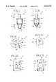
- FIG. 1is a perspective view of a conventional disposable inkjet cartridge
- FIG. 2is a partially exploded view of an inkjet cartridge with adapter, needle valve, and supply tube according to an embodiment of this invention
- FIG. 3is a planar view of the connectors and port of the inkjet cartridge of FIG. 2;
- FIG. 4is a perspective view of the connectors and port of FIG. 3;
- FIG. 5is a cut-away view of the connectors and port of FIG. 4;
- FIG. 6is a cut-away view of a portion of the inkjet cartridge and port of FIG. 2;
- FIG. 7is a planar view of the needle valve of FIG. 2;
- FIG. 8is a planar view of the needle valve of FIG. 2 showing a needle
- FIG. 9is a perspective view of the adapter of FIG. 2;
- FIG. 10is a planar view of the adapter of FIG. 9;
- FIG. 11is another planar view of the adapter of FIG. 9;
- FIG. 12is another planar view of the adapter of FIG. 9.
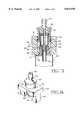
- FIG. 13is a cut-away view showing the adapter and needle valve attached to a portion of the inkjet cartridge housing of FIG. 2;
- FIG. 14is a perspective view of an adapter with an integral needle valve.
- FIG. 1shows a conventional disposable inkjet printing cartridge 10.
- the cartridge 10includes a housing 12 which defines an internal reservoir 14 for storing ink.
- a printhead 26 with inkjet nozzlesis mounted to the housing 12. The printhead receives ink from the reservoir 14 and ejects ink droplets during a printing operation.
- a protruding grip 18extends from the housing 12 enabling convenient installation and removal from a print carriage (not shown) within an inkjet printer (not shown).
- FIG. 2shows a disposable inkjet cartridge 20 which is adapted for continuous or intermittent refilling.
- the cartridge 20includes a housing 22 which defines an internal reservoir 24 for storing ink.
- a printhead 26 with inkjet nozzlesis mounted to the housing 22.
- the printhead 26receives ink from the reservoir 24 and ejects ink droplets while the cartridge 20 scans back and forth along a print carriage during a printing operation.
- a protruding grip 28extends from the housing 22 enabling convenient installation and removal from a print carriage (not shown) within an inkjet printer (not shown).
- the grip 28is formed on an external surface of the housing 22.
- FIGS. 3-5show additional detail of the grip 28.
- the grip 28differs from the conventional grip 18 of FIG. 1.
- the grip 28includes two H-shaped connectors 30, 32 on opposing sides of a cylindrical port 34.
- Each connector 30, 32is formed by two side walls 38,40 and a cross-beam 42.
- the connectors 30, 32are aligned on opposing sides of the port 34 oriented with the cross-beams 42 facing each other, and the side walls 38 aligned and the side walls 40 aligned.
- the cross-beams 42each define a ridge 44 and an incline 45, as shown most clearly in FIG. 5. In one embodiment the ridges 44 extend outward away from the port 34.
- the side walls 38, 40 and the cross-beams 42extend to a common height defining connectors 30, 32 to be of a common height.
- the port 34has an outer diameter equal to or less than the outer dimensional length from connector side wall 40 to connector side 42.
- the port 34extends to a height equal to the height of the connectors 30, 32.
- Coaxially aligned within the portis a fluid interface tube 36.
- the interface tube 36provides fluid communication between the port 34 and the internal reservoir 24.
- the interface tubeis fixed.
- the interface tubemoves between an open position and a closed position.
- FIGS. 2 and 7-8show a needle valve 50 which is to be connected to the inkjet cartridge housing 20 at the port 34.
- the needle valve 50has a central cylindrical housing 52, a first end 54 and a second end 56.
- the first end 54is tapered to receive a flexible tube 58 (see FIG. 2) from an external ink supply reservoir (not shown).
- the second end 56is retractable under force into the central housing 52.
- the second end 56however, is biased to an extended position.
- an internal needle 60is exposed.
- the needle 60is hollow and extends toward the first end 54 to receive ink from the supply tube 58.
- the cylindrical wall of the needle 60is hidden when the second end 56 is fully extended to its relaxed position. In other embodiments a portion of the needle is exposed even when the second end 56 is fully extended to its relaxed position.
- the second end 56is cylindrical and has, along its widest portion 69, a first diameter.
- a distal portion 68 of the second end 56has a second diameter smaller than the first diameter.
- the second diameteralso is less than the inner diameter of the cartridge port 34.
- An elastomeric seal 65is protruding from a distal edge of the distal portion 68.
- a groove 62is formed on the external surface of the central cylindrical housing 52 toward the second end 56.
- the groove 62extends circumferentially around the cylindrical housing 52.
- a retaining ring 64fits to the groove 62.
- the central housing 52has a ridge 66 toward the first end 54. In some embodiment the ridge 66 abuts the housing 52 toward the first end 54.
- the ridge 66defines a wider diameter than the portion of the housing 52 extending toward the second end 56.
- FIGS. 2 and 9-12show an adapter 70 according to an embodiment of this invention.
- the adapter 70is for removably attaching the needle valve 50 to the inkjet cartridge 20.
- the adapter 70holds the needle valve 50 in place to assure a sealed, stable, reliable connection.
- the adapter 70prevents the needle valve 50 from inadvertently assuming a loose fitting connection to the cartridge 20.
- the adapter 70includes a support member 72 with two leg protrusions or extensions 74, 76.
- the support member 72 and two extensions 74, 76are formed as a single integral structure.
- the support member 72has a first surface 78 and a second opposing surface 80.
- An opening 82extends through the support member 72 from the first surface 78 to the second surface 80.
- the opening 82is cylindrical having a diameter equal to the outer diameter of the needle valve's 50 cylindrical housing 52.
- the opening 82 outer diameterhas sufficient tolerance to allow the needle valve housing 52 to slide into the opening 82.
- Each leg extension 74, 76protrudes from the second surface 80.
- Each leg extension 74, 76also has an inner surface 84 facing each other on opposing sides of the opening 82.
- a recess 86(see FIG. 11) toward the second surface 80.
- a recess 88toward the second surface 80.
- the recesses 86, 88are formed adjacent to the second surface 80. The recesses 86, 88 receive the needle valve retaining ring 64 during installation and attachment of the needle valve 50 to the cartridge 20.
- a ridge 90(see FIGS. 9, 11) is formed along the inner surface 84 of the leg extension 74.
- a ridge 92is formed along the inner surface 86 of the leg extension 76. The ridges 90, 92 serve to clamp the adapter 70 to the connectors 30, 32 of the cartridge 20.
- the adapter 70secures the needle valve 50 to the inkjet cartridge housing 22. Before attaching the adapter 70 to the cartridge 20, the needle valve 50 is coupled to the adapter 70. To do so, the needle valve second end 56 is slid from the adapter first surface 78 through the opening 82.
- the needle valve ridge 66has a diameter wider than the opening 82 preventing the needle valve 50 from sliding all the way through the opening 82.
- the needle valve second end 56extends away from the second surface with the adapter leg extensions 74, 76.
- the needle valve 50is moved within the opening to align the needle valve groove 62 with the leg extensions 74, 76 recesses 86, 88.
- the groove 62 and recesses 86, 88align into a common plane.
- the retaining ring 64then is slid along the common plane through the recesses and around the needle valve at the groove 62.
- the retaining ring 64mates to the groove 62 about the circumference of the needle valve housing 52.
- the recesses 86, 88prevent the retaining ring 62 from moving out of the common plane. thus, the recesses lock the needle valve in place preventing the needle valve 50 from moving axially within the opening 82 beyond the play of the recesses 86, 88.
- the second end 56extends a length beyond the length of the leg extensions 74, 76. In some embodiments the second end 56 does not extend beyond the leg extensions 74,76, but the needle 60 does.
- the adapter 70 with needle valve 50is now attached to the cartridge housing 22 by sliding the adapter leg extensions 74, 76 onto the cartridge connectors 30, 32.
- the cartridge connectors 30, 32each define a U-shaped portion along which a respective adapter leg extension 74, 76 is pushed.
- the leg extension ridges 90, 92slide along the respective connector 30, 32 cross-beams 42 over the cross-beam ridges 44 onto respective inclines 45.
- the leg extension ridges 90, 92clamp the adapter 70 to the cartridge connectors 30, 32 at the connector inclines 45.
- the ridges 90, 92mate to the ridges 44 and inclines 45 to secure the adapter 70 to the cartridge 20.
- the needle valve second end 56mates to the cartridge port 34.
- a portion 69 of the second end 56has an outer diameter wider than the inner diameter of the port 34. As a result such portion 69 does not mater to the port 34.
- the continued pushing action on the adapter 70therefore forces the second end 56 to retract into the needle valve housing 52.
- the needle 60does not retract and travels into the port 34.
- the needle 60mates to the fluid interface tube 36 within the port.
- the seal 65is located at the distal edge of the second end 56.
- Such sealbutts up against the fluid interface tube 36
- the sealprevents ink exiting the needle into the tube 36 from leaking into or beyond the port 34.
- the sealpushes the tube inward moving the tube from a closed position to an open position.
- the supply tube 58is attached to the needle valve first end 54 at any time before, during or after the installation and attachment of the needle valve 50 and adapter 70 to the cartridge 20.
- the needle valve 50is formed integral to the adapter 70.
- the adapter 70 with needle valve 50are attached to the inkjet cartridge housing 22 in the same manner as described above for the embodiments in which the adapter and needle valve are separate components.
- One advantage of the inventionis that inexpensive disposable inkjet cartridge technology is effectively adapted for intermittent fill or continuous fill ink supply methods. Another advantage is that a reliable connection is achieved between an inkjet cartridge and an ink supply reservoir.
- leg extension ridges 90, 92face inward toward the opening 82 and the cartridge connector ridges 44 correspondingly face outward away from the port 34, the orientations may differ.
- the leg extension ridges 90, 92are on opposite surfaces of the extensions 74, 76 protruding outward away from the opening 82.
- the connector ridges 44face inward toward the port 34.
- the U-shaped portion of the connectors 30, 32extend in a reversed direction.
- the cartridge connectors 30, 32are cylindrical, instead of H-shaped and the adapter legs correspondingly are cylindrical instead of rectilinear.
- the leg extensionsmate to the connectors and snap into place by action between ridges of the connectors (or leg extensions) and recesses along the leg extensions (or connectors).
- the needle valveseals to the adapter and the adapter includes a fluid interface between the needle valve and inkjet cartridge.
- the humidor providing a seal for the internal needleis formed of soft silicon, foamed silica, foamed EPDM or other pliable material.
- the needle valveattaches to the cartridge the needle covering is pushed back into the pliable material.
- a springbiases the needle cover closed. When the needle valve is attached to the cartridge the attaching action causes the needle cover to retract compressing the spring and exposing the needle. Therefore, the foregoing description should not be taken as limiting the scope of the inventions which are defined by the appended claims.
Landscapes
- Ink Jet (AREA)
Abstract
Description
Claims (19)
Priority Applications (5)
| Application Number | Priority Date | Filing Date | Title |
|---|---|---|---|
| US08/726,587US5874976A (en) | 1996-10-07 | 1996-10-07 | Inkjet cartridge fill port adapter |
| US08/805,859US6076920A (en) | 1995-05-31 | 1997-03-03 | Replaceable ink supply module (bag/box/tube/valve) for replenishment of on-carriage inkjet printhead |
| US09/034,721US6113229A (en) | 1996-10-07 | 1998-03-04 | Interchangeable fluid interconnect attachment and interface |
| US09/045,148US6120132A (en) | 1996-10-07 | 1998-03-19 | Assembly technique using modular ink delivery components for installation in an inkjet printer |
| US10/386,806US6736495B2 (en) | 1991-06-19 | 2003-03-10 | Replenishment system with an open-valve printhead fill port continuously connected to a liquid supply |
Applications Claiming Priority (1)
| Application Number | Priority Date | Filing Date | Title |
|---|---|---|---|
| US08/726,587US5874976A (en) | 1996-10-07 | 1996-10-07 | Inkjet cartridge fill port adapter |
Related Child Applications (3)
| Application Number | Title | Priority Date | Filing Date |
|---|---|---|---|
| US08/805,859Continuation-In-PartUS6076920A (en) | 1995-05-31 | 1997-03-03 | Replaceable ink supply module (bag/box/tube/valve) for replenishment of on-carriage inkjet printhead |
| US09/034,721Continuation-In-PartUS6113229A (en) | 1996-10-07 | 1998-03-04 | Interchangeable fluid interconnect attachment and interface |
| US4515098AContinuation-In-Part | 1991-06-19 | 1998-03-19 |
Publications (1)
| Publication Number | Publication Date |
|---|---|
| US5874976Atrue US5874976A (en) | 1999-02-23 |
Family
ID=24919218
Family Applications (1)
| Application Number | Title | Priority Date | Filing Date |
|---|---|---|---|
| US08/726,587Expired - LifetimeUS5874976A (en) | 1991-06-19 | 1996-10-07 | Inkjet cartridge fill port adapter |
Country Status (1)
| Country | Link |
|---|---|
| US (1) | US5874976A (en) |
Cited By (28)
| Publication number | Priority date | Publication date | Assignee | Title |
|---|---|---|---|---|
| US6059401A (en)* | 1998-03-19 | 2000-05-09 | Hewlett-Packard Company | Alignment coupling device for manually connecting an ink supply to an inkjet print cartridge |
| US6076920A (en)* | 1995-05-31 | 2000-06-20 | Hewlett-Packard Company | Replaceable ink supply module (bag/box/tube/valve) for replenishment of on-carriage inkjet printhead |
| US6113229A (en)* | 1996-10-07 | 2000-09-05 | Hewlett-Packard Company | Interchangeable fluid interconnect attachment and interface |
| US6120132A (en)* | 1996-10-07 | 2000-09-19 | Hewlett-Packard Company | Assembly technique using modular ink delivery components for installation in an inkjet printer |
| US6241347B1 (en)* | 1997-03-03 | 2001-06-05 | Hewlett-Packard Company | Inkjet printing with replaceable set of ink-related components (printhead/service module/ink supply) for each color of ink |
| US6270210B1 (en)* | 1996-10-07 | 2001-08-07 | Seiko Epson Corporation | Method for constructing an ink cartridge |
| US6394503B1 (en) | 2000-03-23 | 2002-05-28 | Lexmark International, Inc. | System for securing tubing |
| US6676252B2 (en) | 2002-04-24 | 2004-01-13 | Hewlett-Packard Development Company, L.P. | Printer ink cartridge and method of assembling same |
| SG103328A1 (en)* | 1999-03-29 | 2004-04-29 | Seiko Epson Corp | Method for filling ink into ink cartridge |
| US6736495B2 (en) | 1991-06-19 | 2004-05-18 | Hewlett-Packard Development Company, Lp. | Replenishment system with an open-valve printhead fill port continuously connected to a liquid supply |
| US6799840B2 (en)* | 2001-08-22 | 2004-10-05 | Canon Kabushiki Kaisha | Ink supply mechanism and inkjet recording apparatus including the ink supply mechanism |
| FR2856172A1 (en)* | 2003-06-16 | 2004-12-17 | Neopost Ind | POSTAGE MACHINE WITH INTEGRATED INK SUPPLY DEVICE |
| US20050052508A1 (en)* | 2003-09-10 | 2005-03-10 | Wirth Steven J. | Ink jet print system including print cartridge |
| US20050225592A1 (en)* | 2004-04-07 | 2005-10-13 | Stratitec Inc. | Inkjet cartridge cleaning devices |
| CN1299914C (en)* | 2003-02-21 | 2007-02-14 | 高全德 | Automatic ink feeder of ink-jet printer |
| WO2013158093A1 (en)* | 2012-04-18 | 2013-10-24 | Hewlett-Packard Development Company, L.P. | Fluid coupling |
| USD744586S1 (en)* | 2014-02-12 | 2015-12-01 | Samsung Electronics Co., Ltd. | Cartridge |
| US20170036787A1 (en)* | 2015-08-03 | 2017-02-09 | Xyzprinting, Inc. | Material filling apparatus for 3d printing |
| JP2017222152A (en)* | 2016-06-10 | 2017-12-21 | セイコーエプソン株式会社 | Ink supply container, ink supply system, and adapter for ink supply |
| KR20190016018A (en)* | 2016-06-10 | 2019-02-15 | 세이코 엡슨 가부시키가이샤 | Ink supply container, ink supply system and adapter for ink supply |
| CN109383131A (en)* | 2017-08-03 | 2019-02-26 | 精工爱普生株式会社 | The manufacturing method of ink replenishing container, ink replenishing container |
| EP3470230A4 (en)* | 2016-06-10 | 2019-12-25 | Seiko Epson Corporation | INK FILLING CONTAINER AND INK FILLING SYSTEM |
| CN111746136A (en)* | 2016-06-10 | 2020-10-09 | 精工爱普生株式会社 | Ink replenishment container |
| JP2021066183A (en)* | 2021-01-12 | 2021-04-30 | セイコーエプソン株式会社 | Ink supply container and ink supply system |
| US11001068B2 (en) | 2016-06-10 | 2021-05-11 | Seiko Epson Corporation | Ink replenish container |
| US11117379B2 (en) | 2016-06-10 | 2021-09-14 | Seiko Epson Corporation | Ink replenish container |
| US11192380B2 (en) | 2017-01-26 | 2021-12-07 | Seiko Epson Corporation | Ink bottle and bottle set |
| US11667123B2 (en) | 2016-06-10 | 2023-06-06 | Seiko Epson Corporation | Ink refill container and ink refill system |
Citations (16)
| Publication number | Priority date | Publication date | Assignee | Title |
|---|---|---|---|---|
| US3503636A (en)* | 1966-11-29 | 1970-03-31 | Ray B Bower | Conduit joint assembly |
| US4429320A (en)* | 1979-09-21 | 1984-01-31 | Canon Kabushiki Kaisha | Ink jet recording apparatus |
| US4561682A (en)* | 1982-09-03 | 1985-12-31 | Rain Bird Consumer Products Mfg. Corp. | Quick connect coupling |
| JPS6112347A (en)* | 1984-06-29 | 1986-01-20 | Canon Inc | recording device |
| US4700202A (en)* | 1983-02-23 | 1987-10-13 | Sharp Kabushiki Kaisha | Ink cartridge in an ink jet system printer |
| US4760409A (en)* | 1986-07-31 | 1988-07-26 | Canon Kabushiki Kaisha | Ink supply device in an ink jet recording apparatus |
| US4928126A (en)* | 1984-02-09 | 1990-05-22 | Canon Kk | Ink container with dual-member sealing closure |
| US4967207A (en)* | 1989-07-26 | 1990-10-30 | Hewlett-Packard Company | Ink jet printer with self-regulating refilling system |
| US4999652A (en)* | 1987-12-21 | 1991-03-12 | Hewlett-Packard Company | Ink supply apparatus for rapidly coupling and decoupling a remote ink source to a disposable ink jet pen |
| JPH05162330A (en)* | 1991-12-11 | 1993-06-29 | Canon Inc | Ink jet recording apparatus |
| US5280300A (en)* | 1991-08-27 | 1994-01-18 | Hewlett-Packard Company | Method and apparatus for replenishing an ink cartridge |
| US5293913A (en)* | 1991-07-12 | 1994-03-15 | Minnesota Mining And Manufacturing Company | Bottle keying system |
| US5369429A (en)* | 1993-10-20 | 1994-11-29 | Lasermaster Corporation | Continuous ink refill system for disposable ink jet cartridges having a predetermined ink capacity |
| US5400573A (en)* | 1993-12-14 | 1995-03-28 | Crystal; Richard G. | Kit and method for opening, refilling and sealing a cartridge |
| US5526853A (en)* | 1994-08-17 | 1996-06-18 | Mcgaw, Inc. | Pressure-activated medication transfer system |
| US5673073A (en)* | 1994-09-29 | 1997-09-30 | Hewlett-Packard Company | Syringe for filling print cartridge and establishing correct back pressure |
- 1996
- 1996-10-07USUS08/726,587patent/US5874976A/ennot_activeExpired - Lifetime
Patent Citations (16)
| Publication number | Priority date | Publication date | Assignee | Title |
|---|---|---|---|---|
| US3503636A (en)* | 1966-11-29 | 1970-03-31 | Ray B Bower | Conduit joint assembly |
| US4429320A (en)* | 1979-09-21 | 1984-01-31 | Canon Kabushiki Kaisha | Ink jet recording apparatus |
| US4561682A (en)* | 1982-09-03 | 1985-12-31 | Rain Bird Consumer Products Mfg. Corp. | Quick connect coupling |
| US4700202A (en)* | 1983-02-23 | 1987-10-13 | Sharp Kabushiki Kaisha | Ink cartridge in an ink jet system printer |
| US4928126A (en)* | 1984-02-09 | 1990-05-22 | Canon Kk | Ink container with dual-member sealing closure |
| JPS6112347A (en)* | 1984-06-29 | 1986-01-20 | Canon Inc | recording device |
| US4760409A (en)* | 1986-07-31 | 1988-07-26 | Canon Kabushiki Kaisha | Ink supply device in an ink jet recording apparatus |
| US4999652A (en)* | 1987-12-21 | 1991-03-12 | Hewlett-Packard Company | Ink supply apparatus for rapidly coupling and decoupling a remote ink source to a disposable ink jet pen |
| US4967207A (en)* | 1989-07-26 | 1990-10-30 | Hewlett-Packard Company | Ink jet printer with self-regulating refilling system |
| US5293913A (en)* | 1991-07-12 | 1994-03-15 | Minnesota Mining And Manufacturing Company | Bottle keying system |
| US5280300A (en)* | 1991-08-27 | 1994-01-18 | Hewlett-Packard Company | Method and apparatus for replenishing an ink cartridge |
| JPH05162330A (en)* | 1991-12-11 | 1993-06-29 | Canon Inc | Ink jet recording apparatus |
| US5369429A (en)* | 1993-10-20 | 1994-11-29 | Lasermaster Corporation | Continuous ink refill system for disposable ink jet cartridges having a predetermined ink capacity |
| US5400573A (en)* | 1993-12-14 | 1995-03-28 | Crystal; Richard G. | Kit and method for opening, refilling and sealing a cartridge |
| US5526853A (en)* | 1994-08-17 | 1996-06-18 | Mcgaw, Inc. | Pressure-activated medication transfer system |
| US5673073A (en)* | 1994-09-29 | 1997-09-30 | Hewlett-Packard Company | Syringe for filling print cartridge and establishing correct back pressure |
Cited By (63)
| Publication number | Priority date | Publication date | Assignee | Title |
|---|---|---|---|---|
| US6736495B2 (en) | 1991-06-19 | 2004-05-18 | Hewlett-Packard Development Company, Lp. | Replenishment system with an open-valve printhead fill port continuously connected to a liquid supply |
| US6076920A (en)* | 1995-05-31 | 2000-06-20 | Hewlett-Packard Company | Replaceable ink supply module (bag/box/tube/valve) for replenishment of on-carriage inkjet printhead |
| US6270210B1 (en)* | 1996-10-07 | 2001-08-07 | Seiko Epson Corporation | Method for constructing an ink cartridge |
| US6120132A (en)* | 1996-10-07 | 2000-09-19 | Hewlett-Packard Company | Assembly technique using modular ink delivery components for installation in an inkjet printer |
| US6113229A (en)* | 1996-10-07 | 2000-09-05 | Hewlett-Packard Company | Interchangeable fluid interconnect attachment and interface |
| US6239822B1 (en)* | 1997-03-03 | 2001-05-29 | Hewlett-Packard Company | Replaceable ink supply module (bag/box/tube/valve) for replenishment of on-carriage inkjet printhead |
| US6241347B1 (en)* | 1997-03-03 | 2001-06-05 | Hewlett-Packard Company | Inkjet printing with replaceable set of ink-related components (printhead/service module/ink supply) for each color of ink |
| US6059401A (en)* | 1998-03-19 | 2000-05-09 | Hewlett-Packard Company | Alignment coupling device for manually connecting an ink supply to an inkjet print cartridge |
| SG103328A1 (en)* | 1999-03-29 | 2004-04-29 | Seiko Epson Corp | Method for filling ink into ink cartridge |
| US6394503B1 (en) | 2000-03-23 | 2002-05-28 | Lexmark International, Inc. | System for securing tubing |
| US6799840B2 (en)* | 2001-08-22 | 2004-10-05 | Canon Kabushiki Kaisha | Ink supply mechanism and inkjet recording apparatus including the ink supply mechanism |
| US6676252B2 (en) | 2002-04-24 | 2004-01-13 | Hewlett-Packard Development Company, L.P. | Printer ink cartridge and method of assembling same |
| CN1299914C (en)* | 2003-02-21 | 2007-02-14 | 高全德 | Automatic ink feeder of ink-jet printer |
| FR2856172A1 (en)* | 2003-06-16 | 2004-12-17 | Neopost Ind | POSTAGE MACHINE WITH INTEGRATED INK SUPPLY DEVICE |
| EP1488931A1 (en)* | 2003-06-16 | 2004-12-22 | Neopost Industrie | Franking machine with integrated ink supplying device |
| US20080184901A1 (en)* | 2003-06-16 | 2008-08-07 | Neopost Industrie | Franking machine incorporating an integrated ink supply device |
| US7404629B2 (en) | 2003-06-16 | 2008-07-29 | Neopost Technologies | Franking machine incorporating an integrated ink supply device |
| US20050001861A1 (en)* | 2003-06-16 | 2005-01-06 | Regis Desire | Franking machine incorporating an integrated ink supply device |
| US6935731B2 (en) | 2003-09-10 | 2005-08-30 | Eastman Kodak Company | Ink jet print system including print cartridge |
| WO2005025876A1 (en)* | 2003-09-10 | 2005-03-24 | Eastman Kodak Company | Ink jet print system including print cartridge |
| US20050052508A1 (en)* | 2003-09-10 | 2005-03-10 | Wirth Steven J. | Ink jet print system including print cartridge |
| US20050225592A1 (en)* | 2004-04-07 | 2005-10-13 | Stratitec Inc. | Inkjet cartridge cleaning devices |
| WO2013158093A1 (en)* | 2012-04-18 | 2013-10-24 | Hewlett-Packard Development Company, L.P. | Fluid coupling |
| US9261209B2 (en) | 2012-04-18 | 2016-02-16 | Hewlett-Packard Development Company, L.P. | Fluid coupling |
| US9555636B2 (en) | 2012-04-18 | 2017-01-31 | Hewlett-Packard Development Company, L.P. | Printers |
| US10035352B2 (en) | 2012-04-18 | 2018-07-31 | Hewlett-Packard Development Company, L.P. | Printers |
| USD744586S1 (en)* | 2014-02-12 | 2015-12-01 | Samsung Electronics Co., Ltd. | Cartridge |
| CN106426966B (en)* | 2015-08-03 | 2018-09-11 | 三纬国际立体列印科技股份有限公司 | A filler device for 3D prints |
| US20170036787A1 (en)* | 2015-08-03 | 2017-02-09 | Xyzprinting, Inc. | Material filling apparatus for 3d printing |
| US9598185B2 (en)* | 2015-08-03 | 2017-03-21 | Xyzprinting, Inc. | Material filling apparatus for 3D printing |
| CN106426966A (en)* | 2015-08-03 | 2017-02-22 | 三纬国际立体列印科技股份有限公司 | A filler device for 3D prints |
| US11007787B2 (en) | 2016-06-10 | 2021-05-18 | Seiko Epson Corporation | Ink refill container and ink refill system |
| JP2017222152A (en)* | 2016-06-10 | 2017-12-21 | セイコーエプソン株式会社 | Ink supply container, ink supply system, and adapter for ink supply |
| US12296600B2 (en) | 2016-06-10 | 2025-05-13 | Seiko Epson Corporation | Ink refill container, ink refill system, and ink refill adapter |
| EP3470230A4 (en)* | 2016-06-10 | 2019-12-25 | Seiko Epson Corporation | INK FILLING CONTAINER AND INK FILLING SYSTEM |
| EP3470229A4 (en)* | 2016-06-10 | 2019-12-25 | Seiko Epson Corporation | INK FILLING CONTAINER, INK FILLING SYSTEM, AND INK FILLING ADAPTER |
| US10717287B2 (en) | 2016-06-10 | 2020-07-21 | Seiko Epson Corporation | Ink refill container, ink refill system, and ink refill adapter |
| JP2020116962A (en)* | 2016-06-10 | 2020-08-06 | セイコーエプソン株式会社 | Ink supply container |
| US10752003B2 (en) | 2016-06-10 | 2020-08-25 | Seiko Epson Corporation | Ink refill container and ink refill system |
| US11179944B2 (en) | 2016-06-10 | 2021-11-23 | Seiko Epson Corporation | Ink refill container, ink refill system, and ink refill adapter |
| CN111746136A (en)* | 2016-06-10 | 2020-10-09 | 精工爱普生株式会社 | Ink replenishment container |
| US10889123B2 (en) | 2016-06-10 | 2021-01-12 | Seiko Epson Corporation | Ink refill container, ink refill system, and ink refill adapter |
| US12280601B2 (en) | 2016-06-10 | 2025-04-22 | Seiko Epson Corporation | Ink refill container and ink refill system |
| US11001068B2 (en) | 2016-06-10 | 2021-05-11 | Seiko Epson Corporation | Ink replenish container |
| US11926162B2 (en) | 2016-06-10 | 2024-03-12 | Seiko Epson Corporation | Ink refill container and ink refill system |
| KR20190016018A (en)* | 2016-06-10 | 2019-02-15 | 세이코 엡슨 가부시키가이샤 | Ink supply container, ink supply system and adapter for ink supply |
| RU2749330C2 (en)* | 2016-06-10 | 2021-06-08 | Сейко Эпсон Корпорейшн | Ink refill container and ink refill system |
| RU2731027C2 (en)* | 2016-06-10 | 2020-08-28 | Сейко Эпсон Корпорейшн | Ink replenishment container and ink replenishment system |
| US11117379B2 (en) | 2016-06-10 | 2021-09-14 | Seiko Epson Corporation | Ink replenish container |
| AU2022246375B2 (en)* | 2016-06-10 | 2024-09-05 | Seiko Epson Corporation | Ink refill container, ink refill system, and ink refill adapter |
| CN111746136B (en)* | 2016-06-10 | 2022-05-10 | 精工爱普生株式会社 | Ink replenishing container |
| AU2017279290B2 (en)* | 2016-06-10 | 2022-10-13 | Seiko Epson Corporation | Ink refill container, ink refill system, and ink refill adapter |
| US11541662B2 (en) | 2016-06-10 | 2023-01-03 | Seiko Epson Corporation | Ink refill container and ink refill system |
| US11938739B2 (en) | 2016-06-10 | 2024-03-26 | Seiko Epson Corporation | Ink refill container, ink refill system, and ink refill adapter |
| US11639060B2 (en) | 2016-06-10 | 2023-05-02 | Seiko Epson Corporation | Ink refill container, ink refill system, and ink refill adapter |
| USD988398S1 (en) | 2016-06-10 | 2023-06-06 | Seiko Epson Corporation | Ink replenish container |
| US11667123B2 (en) | 2016-06-10 | 2023-06-06 | Seiko Epson Corporation | Ink refill container and ink refill system |
| US11192380B2 (en) | 2017-01-26 | 2021-12-07 | Seiko Epson Corporation | Ink bottle and bottle set |
| US11932022B2 (en) | 2017-01-26 | 2024-03-19 | Seiko Epson Corporation | Ink bottle and bottle set |
| US11597207B2 (en) | 2017-01-26 | 2023-03-07 | Seiko Epson Corporation | Ink bottle and bottle set |
| CN109383131B (en)* | 2017-08-03 | 2021-12-14 | 精工爱普生株式会社 | Ink replenishment container, manufacturing method of ink replenishment container |
| CN109383131A (en)* | 2017-08-03 | 2019-02-26 | 精工爱普生株式会社 | The manufacturing method of ink replenishing container, ink replenishing container |
| JP2021066183A (en)* | 2021-01-12 | 2021-04-30 | セイコーエプソン株式会社 | Ink supply container and ink supply system |
Similar Documents
| Publication | Publication Date | Title |
|---|---|---|
| US5874976A (en) | Inkjet cartridge fill port adapter | |
| US7452063B2 (en) | Inkjet recording apparatus and ink cartridge | |
| US6158851A (en) | Ink valve having a releasable tip for a print cartridge recharge system | |
| KR100235282B1 (en) | Inkjet print cartridge having handle which incorporates an ink fill port | |
| US6796646B2 (en) | Replaceable ink cartridge for ink jet pen | |
| KR100233977B1 (en) | Ink recharger for inkjet print cartridge having sliding valve connectable to print cartridge | |
| AU768894B2 (en) | Techniques for adapting a small form factor ink-jet cartridge for use in a carriage sized for a large form factor cartridge | |
| US6971740B2 (en) | Ink cartridge refill system and method of use | |
| JPS6153235B2 (en) | ||
| US6120132A (en) | Assembly technique using modular ink delivery components for installation in an inkjet printer | |
| KR100235283B1 (en) | Inkjet print cartridge having a first inlet port for initial filling and a second inlet port for ink replenishment without removing the print cartridge from the printer | |
| US6736495B2 (en) | Replenishment system with an open-valve printhead fill port continuously connected to a liquid supply | |
| US6059401A (en) | Alignment coupling device for manually connecting an ink supply to an inkjet print cartridge | |
| US7114800B2 (en) | Ink supply system and ink cartridge | |
| JP3219624B2 (en) | Ink refilling device for ink tank for ink recording head | |
| WO2001019615A1 (en) | Method and apparatus for refilling an ink cartridge with a printhead mounted on it | |
| KR200174627Y1 (en) | Ink refilling bulb of ink cartridge | |
| JPH09131886A (en) | Ink refill device for ink tank for ink recording head | |
| JPH06210870A (en) | Ink container |
Legal Events
| Date | Code | Title | Description |
|---|---|---|---|
| AS | Assignment | Owner name:HEWLETT-PACKARD COMPANY, CALIFORNIA Free format text:ASSIGNMENT OF ASSIGNORS INTEREST;ASSIGNORS:KATON, ROBERT JOSEPH;GUNTHER, MAX S.;SCHEFFELIN, JOSEPH E.;AND OTHERS;REEL/FRAME:008295/0554;SIGNING DATES FROM 19960913 TO 19961122 | |
| STCF | Information on status: patent grant | Free format text:PATENTED CASE | |
| AS | Assignment | Owner name:HEWLETT-PACKARD COMPANY, COLORADO Free format text:MERGER;ASSIGNOR:HEWLETT-PACKARD COMPANY;REEL/FRAME:011523/0469 Effective date:19980520 | |
| FEPP | Fee payment procedure | Free format text:PAYOR NUMBER ASSIGNED (ORIGINAL EVENT CODE: ASPN); ENTITY STATUS OF PATENT OWNER: LARGE ENTITY | |
| FPAY | Fee payment | Year of fee payment:4 | |
| REMI | Maintenance fee reminder mailed | ||
| FPAY | Fee payment | Year of fee payment:8 | |
| FPAY | Fee payment | Year of fee payment:12 | |
| AS | Assignment | Owner name:HEWLETT-PACKARD DEVELOPMENT COMPANY, L.P., TEXAS Free format text:ASSIGNMENT OF ASSIGNORS INTEREST;ASSIGNOR:HEWLETT-PACKARD COMPANY;REEL/FRAME:026945/0699 Effective date:20030131 |