US5873916A - Fuel emulsion blending system - Google Patents
Fuel emulsion blending systemDownload PDFInfo
- Publication number
- US5873916A US5873916AUS09/024,916US2491698AUS5873916AUS 5873916 AUS5873916 AUS 5873916AUS 2491698 AUS2491698 AUS 2491698AUS 5873916 AUS5873916 AUS 5873916A
- Authority
- US
- United States
- Prior art keywords
- fuel
- fuel emulsion
- fluid circuit
- water
- blending
- Prior art date
- Legal status (The legal status is an assumption and is not a legal conclusion. Google has not performed a legal analysis and makes no representation as to the accuracy of the status listed.)
- Expired - Lifetime
Links
Images

Classifications
- F—MECHANICAL ENGINEERING; LIGHTING; HEATING; WEAPONS; BLASTING
- F23—COMBUSTION APPARATUS; COMBUSTION PROCESSES
- F23K—FEEDING FUEL TO COMBUSTION APPARATUS
- F23K5/00—Feeding or distributing other fuel to combustion apparatus
- F23K5/02—Liquid fuel
- F23K5/08—Preparation of fuel
- F23K5/10—Mixing with other fluids
- B—PERFORMING OPERATIONS; TRANSPORTING
- B01—PHYSICAL OR CHEMICAL PROCESSES OR APPARATUS IN GENERAL
- B01F—MIXING, e.g. DISSOLVING, EMULSIFYING OR DISPERSING
- B01F23/00—Mixing according to the phases to be mixed, e.g. dispersing or emulsifying
- B01F23/40—Mixing liquids with liquids; Emulsifying
- B01F23/41—Emulsifying
- B—PERFORMING OPERATIONS; TRANSPORTING
- B01—PHYSICAL OR CHEMICAL PROCESSES OR APPARATUS IN GENERAL
- B01F—MIXING, e.g. DISSOLVING, EMULSIFYING OR DISPERSING
- B01F23/00—Mixing according to the phases to be mixed, e.g. dispersing or emulsifying
- B01F23/40—Mixing liquids with liquids; Emulsifying
- B01F23/49—Mixing systems, i.e. flow charts or diagrams
- C—CHEMISTRY; METALLURGY
- C10—PETROLEUM, GAS OR COKE INDUSTRIES; TECHNICAL GASES CONTAINING CARBON MONOXIDE; FUELS; LUBRICANTS; PEAT
- C10L—FUELS NOT OTHERWISE PROVIDED FOR; NATURAL GAS; SYNTHETIC NATURAL GAS OBTAINED BY PROCESSES NOT COVERED BY SUBCLASSES C10G OR C10K; LIQUIFIED PETROLEUM GAS; USE OF ADDITIVES TO FUELS OR FIRES; FIRE-LIGHTERS
- C10L1/00—Liquid carbonaceous fuels
- C10L1/32—Liquid carbonaceous fuels consisting of coal-oil suspensions or aqueous emulsions or oil emulsions
Definitions
- the present inventionrelates to a fuel blending system, and more particularly to a fuel emulsion blending system for blending an aqueous fuel emulsion from a source of hydrocarbon fuel, a source of water, and a source of aqueous fuel emulsion additives.
- aqueous fuel emulsionstend to reduce or inhibit the formation of nitrogen oxides (NOx) and particulates (i.e. combination of soot and hydrocarbons) by altering the way the fuel is burned in the engine.
- NOxnitrogen oxides
- particulatesi.e. combination of soot and hydrocarbons
- the fuel emulsionsare burned at somewhat lower temperatures than a conventional fuels due to the presence of water. This, coupled with the realization that at higher peak combustion temperatures, more NOx are typically produced in the engine exhaust, one can readily understand the advantage of using aqueous fuel emulsions.
- the problems associated with fuel emulsion separationare very severe inasmuch as most engine operating characteristics are adjusted for a prescribed fuel composition. Where the fuel emulsion composition has changed due to ingredient separation, the engine performance is markedly diminished.
- U.S. Pat. No. 5,535,708discloses a process for forming an emulsion of an aqueous urea solution in diesel fuel and combusting the same for the purposes of reducing NOx emissions from diesel engines.
- U.S. Pat. No. 4,938,606discloses an apparatus for producing an emulsion for internal combustion engines that employs an oil line, a water line, a dosing apparatus and various mixing and storage chambers.
- Another related art process and system for blending a fuel emulsionis disclosed in U.S. Pat. No. 5,298,230 (Argabright) which discloses a specialized process for blending a fuel emulsification system useful for the reduction of NOx in a gas turbine.
- the present inventionaddresses the aforementioned problems associated with separation of aqueous fuel emulsions by providing a blending system and method that enhances the long term stability of such emulsions.
- the present inventionis a fuel emulsion blending system for blending an aqueous fuel emulsion from a source of hydrocarbon fuel, a source of water, and a source of aqueous fuel emulsion additives.
- the blending systemenhances the long term stability of such aqueous fuel emulsions over that of conventional blending systems.
- the present inventionmay be characterized as a fuel emulsion blending system including a first inlet circuit adapted for receiving hydrocarbon fuel from the source of hydrocarbon fuel; a second inlet circuit adapted for receiving aqueous fuel emulsion additives from the source of aqueous fuel emulsion additives; and a third inlet circuit adapted for receiving water from the source of water.
- the blending systemfurther includes a first blending station adapted to mix the hydrocarbon fuel and aqueous fuel emulsion additives and a second blending station adapted to mix the hydrocarbon fuel and additive mixture received from the first blending station together with the water received from the source of water. This system is particularly suitable for blending fuel continuous fuel emulsions.
- the blending systemfurther includes an emulsification station downstream of the blending stations which is adapted to emulsify the mixture of hydrocarbon fuel, additives and water to yield a stable aqueous fuel emulsion.
- the present embodiment of the blending systemis operatively associated with a blending system controller which is adapted to govern the flow of the hydrocarbon fuel, water and aqueous fuel emulsion additives thereby controlling the mixing ratio in accordance with prescribed blending ratios.
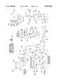
- FIG. 1is a schematic representation of the aqueous fuel emulsion blending station in accordance with the present invention
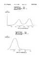
- FIG. 2is a graph that depicts the preferred droplet size distribution for a water continuous fuel emulsion prepared using the disclosed fuel emulsion blending system
- FIG. 3is a graph that depicts the preferred droplet size distribution for an oil continuous fuel emulsion.
- FIG. 4is a schematic representation of an alternate embodiment of the aqueous fuel emulsion blending station in accordance with the present invention.
- FIG. 1there is shown a schematic representation of an aqueous fuel emulsion blending system 12 having a plurality of ingredient inlets and an aqueous fuel emulsion outlet 14.
- the preferred embodiment of the fuel blending system 12comprises a first fluid circuit 16 adapted for receiving hydrocarbon fuel at a first ingredient inlet 18 from a source of hydrocarbon fuel (not shown) and a second fluid circuit 20 adapted for receiving fuel emulsion additives at a second ingredient inlet 22 from an additive storage tank 24 or similar such source of fuel emulsion additives.
- the first fluid circuit 16includes a fuel pump 26 for transferring the hydrocarbon fuel, preferably a diesel fuel (although other hydrocarbon fuels can be used), from the source of hydrocarbon fuel to the blending system 12 at a selected flow rate, a 2 to 10 micron filter 28, and a flow measurement device 30 adapted to measure the flow rate of the incoming hydrocarbon fuel stream.
- the second fluid circuit 20also includes a pump 32 for transferring the additives from the storage tank 24 to the blending system 12 at prescribed flow rates. The fuel additive flow rate within the second fluid circuit 20 is controlled by a flow control valve 34 interposed between the additive storage tank 24 and the pump 32.
- the second fluid circuit 20also includes a 2 to 10 micron filter 36 and a flow measurement device 38 adapted to measure the controlled flow rate of the incoming additive stream.
- the signals 40,42 generated from the flow measurement devices 30,38 associated with the first and second fluid circuitsare further coupled as inputs to a blending system controller 44.
- the first fluid circuit 16 transporting the hydrocarbon fuel and the second fluid circuit 20 adapted for supplying the fuel additivesare coupled together and subsequently mixed together using a first in-line mixer 46.
- the resulting mixture of hydrocarbon fuel and fuel additivesis then joined with a purified water stream supplied via a third fluid circuit 50 and subsequently mixed together using a second in-line mixer 52.
- the third fluid circuit 50includes a water pump 54 for transferring the purified water from a source of clean or purified water (not shown) at a selected flow rate to the blending system 12, a particulate filter 56 and a flow measurement device 58 adapted to measure the flow rate of the incoming purified water stream.
- the water pump 54, filter 56 and flow measurement device 58are serially arranged within the third fluid circuit 50.
- the water flow rate within the third fluid circuit 50is preferably controlled using a flow control valve 60 interposed between the clean water source and the water pump 54 proximate the third or water inlet 62.
- the third fluid circuit 50also includes a specific conductance measurement device 64 disposed downstream of the flow measurement device 58 and adapted to monitor the quality of the water supplied to the blending system 12.
- the signals 66,68 generated from the flow measurement device 58 and the specific conductance measurement device 64 or other suitable measurement device in the third fluid circuit 50are provided as inputs to the blending system controller 44. If the water quality is too poor or below a prescribed threshold, the blending system controller 44 disables the blending system 12 until corrective measures are taken. In the preferred embodiment, the water quality threshold, as measured using the specific conductance measurement device 64, should be no greater than 20 microsiemens per centimeter. As indicated above, the purified water from the third fluid circuit 50 is joined with the hydrocarbon fuel and fuel additive mixture and subsequently re-mixed using the second in-line mixer 52 or equivalent blending station equipment.
- the resulting mixture or combination of hydrocarbon fuel, fuel emulsion additives, and purified waterare fed into an emulsification station 70.
- the emulsification station 70includes an aging reservoir 72 and high shear mixing apparatus.
- the aging reservoir 72includes an inlet 74, an outlet 76 and a high volume chamber 78 or reservoir.
- the preferred embodiment of the blending system 12operates using an aging time that is a function of emulsion temperature. For example, a three minute aging time would be appropriate for room temperature mixture of the aqueous fuel emulsion. Thus, in the three minute aging time a blending system operating at an output flow rate of about 15 gallons per minute would utilize a 45 gallon tank as an aging reservoir.
- the incoming stream of hydrocarbon fuel, fuel emulsion additives, and purified waterare fed into the aging reservoir 72 at a location that preferably provides continuous agitation to the reservoir.
- the aging reservoircould include a mechanical mixing device associated therewith.
- the preferred embodiment of the blending system 12also includes a continuous rotor-stator dispersion mill 81, such as the Kady Infinity model manufactured by Kady International in Scarborough, Me., disposed downstream of the aging reservoir 72 which provides the final fuel emulsion at the blending system outlet 14.
- a prescribed percentage of the fuel mixture flowshould bypass the dispersion mill 81.
- Such bypass flowcan be accomplished using a bypass conduit 80 and associated valve 82 located within or near the emulsification station 70.
- Bypassing a prescribed percentage of the mixture flow around the dispersion mill 81yields a final fuel emulsion having a bi-modal droplet size distribution, as generally represented in FIG. 2.
- all of the fuel mixture flowshould be directed through the dispersion mill 81 or similar such high shear mixing device, such as a Ross X-series Mixer Emulsifier. which results in the final fuel emulsion having a droplet size distribution, as generally represented in FIG. 3.
- the blending system controller 44accepts as inputs the signals generated by the various flow measurement devices in the first, second and third fluid circuits, as well as any signals generated by the water quality measurement device together with various operator inputs such as prescribed fuel mix ratios and provides control signals for the flow control valve in the second fluid circuit and the flow control valve in the third fluid circuit.
- the illustrated embodiment of the blending systemis preferably configured such that the hydrocarbon fuel stream is not precisely controlled but is precisely measured.
- the purified water feed line and the fuel additive feed lineare precisely controlled and precisely measured to yield a prescribed water blend fuel mix.
- the illustrated embodimentalso shows the hydrocarbon fuel, purified water and fuel additive streams to be continuous feed so that the proper fuel blend ratio is continuously delivered to the shear pump.
- the above-described blending systemis particularly suited for preparing a water blend fuel or aqueous fuel emulsion that uses a hydrocarbon fuel having a specific gravity in the range of about 0.70to 0.90 and a viscosity in the range of about 1.0 to 30.0 cSt.
- the preferred volumetric ratio of hydrocarbon fuelis between about 50% to 90% of the total volume of the aqueous fuel emulsion.
- the preferred volumetric ratio of purified wateris between about 10% to 50% of the total volume of the aqueous fuel emulsion whereas the volumetric ratio of additives is between about 0.5% to 10.3% of the total volume of aqueous fuel emulsion.
- hydrocarbon fuelis preferably a diesel fuel although alternative hydrocarbon fuels such as naphtha, gasoline, synthetic fuels or combinations thereof could also be used as the base hydrocarbon fuel.
- the fuel emulsion additives used in the above described blending systemmay include one or more of the following ingredients including surfactants, emulsifiers, detergents, defoamers, lubricants, corrosion inhibitors, and anti-freeze inhibitors such as methanol. Collectively, the additives have a specific gravity in the range of about 0.80 to 0.90 and a viscosity of about 0.8 cSt.
- FIG. 4there is shown a schematic representation of an alternate embodiment of the fuel emulsion blending system 84.
- the embodiment of FIG. 4is similar to the embodiment of FIG. 1 except for the inclusion of a fourth fluid circuit 86 and several other features of the fuel emulsion blending system 84 described herein. Much of the detailed description of many of the components or elements common to both embodiments are provided above with reference to FIG. 1 and thus will not be repeated here.
- the fuel emulsion blending system 84 illustrated in FIG. 4includes four fluid circuits inlets 18,22,62,88 and a fuel emulsion outlet 14.
- the first fluid circuit 16is adapted for receiving hydrocarbon fuel at the first ingredient inlet 18 from a source of hydrocarbon fuel (not shown) while the second fluid circuit 20 is adapted for receiving fuel emulsion additives at a second ingredient inlet 22 from an additive storage tank 24', preferably a heated source of fuel emulsion additives.
- the third fluid circuit 50is adapted for receiving water at the third ingredient inlet 62 from a source of water (not shown) while the fourth fluid circuit 86 is adapted for receiving methanol at the fourth ingredient inlet 88 from an appropriate source of methanol (not shown).
- the first fluid circuit 16includes a fuel pump 26 for transferring the hydrocarbon fuel, preferably a diesel fuel, from the source of hydrocarbon fuel to the blending system 84 at a selected flow rate, a filter 28, and a flow measurement device 30 adapted to measure the flow rate of the incoming hydrocarbon fuel stream.
- the first fluid circuit 16includes a heater 90 or other means for heating the hydrocarbon fuel component to a specified minimum temperature (e.g. 10 degrees C.).
- the second fluid circuit 20also includes a pump 32 for transferring the fuel emulsion additives from the storage tank 24' where the additives are maintained at a specified minimum temperature to the blending system 84 at a prescribed flow rate.
- the fuel additive flow rate within the second fluid circuit 20is controlled by a flow control valve 34 interposed between the additive storage tank 24' and the fuel emulsion additive pump 32.
- the second fluid circuit 20also includes a filter 36 and a flow measurement device 38 adapted to measure the flow rate of the incoming additive stream.
- the fourth fluid circuit 86includes a pump 92 and flow control valve 94, filter 96, heating element 98 and a flow measurement device 100.
- the pump 92, filter 96, heater 98, and flow measurement device 100are serially arranged within the fourth fluid circuit 86.
- the methanol, ethanol or other antifreeze flow rate within the fourth fluid circuit 86is preferably controlled using the flow control valve 94 which is interposed between the methanol source (not shown) and the pump 92 proximate the fourth ingredient inlet 88.
- the final or third fluid circuit 50is the water fluid circuit which preferably includes a water purification system 102 such as a reverse osmosis purification system that heats and purifies the supplied water to prescribed temperatures and levels of purity, respectively.
- This third fluid circuit 50also includes a water pump 54 and water flow control valve 60 for transferring the purified water at a selected flow rate to the blending system 84.
- the third fluid circuit 50also includes a flow measurement device 58 adapted to measure the flow rate of the incoming purified water stream and a specific conductance measurement device 64 or other suitable measurement devices adapted to monitor the quality of the water supplied to the blending system 84.
- the operation of the fuel emulsion blending system 84 illustrated in FIG. 4,involves selective mixing of the ingredients from each of the fluid circuits.
- the fourth fluid circuit 86 transporting the methanol and the second fluid circuit 20 adapted for supplying the fuel additivesare coupled together and subsequently mixed together using an in-line mixer 104.
- the resulting mixture of methanol and fuel additivesis then joined with the first fluid circuit 16 supplying the hydrocarbon fuel component.
- Another in-line mixer 46is used to mix the hydrocarbon fuel, fuel additives and methanol together.
- the purified water stream supplied via a third fluid circuit 50is then added to the mixture and subsequently mixed together using yet another in-line mixer 52.
- the resulting mixture or combination of hydrocarbon fuel, fuel emulsion additives, methanol and purified waterare fed into an emulsification station 70.
- the emulsification station 70includes the aging reservoir 72, and also includes a continuous rotor-stator dispersion mill 81, such as the Kady Infinity Dispersion Mill disposed downstream of the aging reservoir 72 which provides the final aqueous fuel emulsion at the blending system outlet 14.
- a final fuel emulsion density, viscosity, conductivity and/or opacity measurement device 106which monitors the density and/or viscosity of the final fuel blend.
- the signals 40,42,66,108 generated from the flow measurement devices associated with the four fluid circuits together with the signals 68,110 generated by the specific conductance measurement device 64 in the third fluid circuit 50 and the final emulsion density, opacity, conductance and/or viscosity measurement device 106are provided as inputs to the blending system controller 44.
- the blending system controller 44also accepts various operator inputs 112 such as prescribed fuel mix ratios and provides output control signals 114 for the flow control valves 34,60,94 in the second, third and fourth fluid circuits and, if appropriate the emulsification station 70.
- the present inventionthus provides a fuel emulsion blending system for blending an aqueous fuel emulsion from a source of hydrocarbon fuel, a source of water, and a source of fuel emulsion additives, including methanol. While the invention herein disclosed has been described by means of specific embodiments and processes associated therewith, numerous modifications and variations can be made thereto by those skilled in the art without departing from the scope of the invention as set forth in the claims or sacrificing all its material advantages.
Landscapes
- Chemical & Material Sciences (AREA)
- Engineering & Computer Science (AREA)
- Chemical Kinetics & Catalysis (AREA)
- Oil, Petroleum & Natural Gas (AREA)
- General Chemical & Material Sciences (AREA)
- Organic Chemistry (AREA)
- Combustion & Propulsion (AREA)
- Mechanical Engineering (AREA)
- General Engineering & Computer Science (AREA)
- Liquid Carbonaceous Fuels (AREA)
- Nozzles (AREA)
- Feeding And Controlling Fuel (AREA)
Abstract
Description
Claims (24)
Priority Applications (11)
| Application Number | Priority Date | Filing Date | Title |
|---|---|---|---|
| US09/024,916US5873916A (en) | 1998-02-17 | 1998-02-17 | Fuel emulsion blending system |
| US09/201,597US6447556B1 (en) | 1998-02-17 | 1998-11-30 | Fuel emulsion blending system |
| DE69921457TDE69921457T2 (en) | 1998-02-17 | 1999-02-05 | FUEL MULTILATION MIXING SYSTEM |
| PCT/US1999/002469WO1999041339A1 (en) | 1998-02-17 | 1999-02-05 | Fuel emulsion blending system |
| JP2000531523AJP4491133B2 (en) | 1998-02-17 | 1999-02-05 | Fuel emulsion mixing system |
| AU25850/99AAU747185B2 (en) | 1998-02-17 | 1999-02-05 | Fuel emulsion blending system |
| CA002321045ACA2321045C (en) | 1998-02-17 | 1999-02-05 | Fuel emulsion blending system |
| EP19990905761EP1058719B1 (en) | 1998-02-17 | 1999-02-05 | Fuel emulsion blending system |
| AT99905761TATE280819T1 (en) | 1998-02-17 | 1999-02-05 | FUEL EMULSION MIXING SYSTEM |
| BRPI9908103-2ABR9908103B1 (en) | 1998-02-17 | 1999-02-05 | fuel emulsion mixing system and method for mixing a fuel emulsion. |
| DK99905761TDK1058719T3 (en) | 1998-02-17 | 1999-02-05 | fuel emulsion |
Applications Claiming Priority (1)
| Application Number | Priority Date | Filing Date | Title |
|---|---|---|---|
| US09/024,916US5873916A (en) | 1998-02-17 | 1998-02-17 | Fuel emulsion blending system |
Related Child Applications (1)
| Application Number | Title | Priority Date | Filing Date |
|---|---|---|---|
| US09/201,597Continuation-In-PartUS6447556B1 (en) | 1998-02-17 | 1998-11-30 | Fuel emulsion blending system |
Publications (1)
| Publication Number | Publication Date |
|---|---|
| US5873916Atrue US5873916A (en) | 1999-02-23 |
Family
ID=21823026
Family Applications (1)
| Application Number | Title | Priority Date | Filing Date |
|---|---|---|---|
| US09/024,916Expired - LifetimeUS5873916A (en) | 1998-02-17 | 1998-02-17 | Fuel emulsion blending system |
Country Status (10)
| Country | Link |
|---|---|
| US (1) | US5873916A (en) |
| EP (1) | EP1058719B1 (en) |
| JP (1) | JP4491133B2 (en) |
| AT (1) | ATE280819T1 (en) |
| AU (1) | AU747185B2 (en) |
| BR (1) | BR9908103B1 (en) |
| CA (1) | CA2321045C (en) |
| DE (1) | DE69921457T2 (en) |
| DK (1) | DK1058719T3 (en) |
| WO (1) | WO1999041339A1 (en) |
Cited By (65)
| Publication number | Priority date | Publication date | Assignee | Title |
|---|---|---|---|---|
| WO1999063025A1 (en)* | 1998-06-05 | 1999-12-09 | Clean Fuels Technology, Inc. | Stabile fuel emulsions and method of making |
| WO1999063024A1 (en)* | 1998-06-05 | 1999-12-09 | Clean Fuels Technology, Inc. | Stabile invert fuel emulsion compositions and method of making |
| WO1999063026A1 (en)* | 1998-06-05 | 1999-12-09 | Clean Fuels Technology, Inc. | High stability fuel compositions |
| DE19917753A1 (en)* | 1999-04-20 | 2000-10-26 | Ulrich Friesen | Emulsion-type fuel for an internal combustion engine comprises a fuel, an emulsifier, and deionized water to reduce engine deposits |
| WO2001004239A1 (en)* | 1999-07-07 | 2001-01-18 | The Lubrizol Corporation | Process and apparatus for making aqueous hydrocarbon fuel compositions, and aqueous hydrocarbon fuel compositions |
| US6280485B1 (en) | 1998-09-14 | 2001-08-28 | The Lubrizol Corporation | Emulsified water-blended fuel compositions |
| US6368367B1 (en) | 1999-07-07 | 2002-04-09 | The Lubrizol Corporation | Process and apparatus for making aqueous hydrocarbon fuel compositions, and aqueous hydrocarbon fuel composition |
| US6383237B1 (en) | 1999-07-07 | 2002-05-07 | Deborah A. Langer | Process and apparatus for making aqueous hydrocarbon fuel compositions, and aqueous hydrocarbon fuel compositions |
| US6419714B2 (en) | 1999-07-07 | 2002-07-16 | The Lubrizol Corporation | Emulsifier for an acqueous hydrocarbon fuel |
| US6447556B1 (en)* | 1998-02-17 | 2002-09-10 | Clean Fuel Technology, Inc. | Fuel emulsion blending system |
| US6530964B2 (en) | 1999-07-07 | 2003-03-11 | The Lubrizol Corporation | Continuous process for making an aqueous hydrocarbon fuel |
| US6589301B1 (en)* | 1998-12-08 | 2003-07-08 | Elf Antar France | Method for preparing an emulsified fuel and implementing device |
| US20030131526A1 (en)* | 2001-04-27 | 2003-07-17 | Colt Engineering Corporation | Method for converting heavy oil residuum to a useful fuel |
| US6606856B1 (en) | 2000-03-03 | 2003-08-19 | The Lubrizol Corporation | Process for reducing pollutants from the exhaust of a diesel engine |
| US6607566B1 (en)* | 1998-07-01 | 2003-08-19 | Clean Fuel Technology, Inc. | Stabile fuel emulsions and method of making |
| US6637381B2 (en) | 2001-10-09 | 2003-10-28 | Southwest Research Institute | Oxygenated fuel plus water injection for emissions control in compression ignition engines |
| US6652607B2 (en) | 1999-07-07 | 2003-11-25 | The Lubrizol Corporation | Concentrated emulsion for making an aqueous hydrocarbon fuel |
| US6656236B1 (en)* | 1997-12-12 | 2003-12-02 | Clean Fuel Technology, Inc. | Constant heating value aqueous fuel mixture and method for formulating the same |
| US20040025416A1 (en)* | 2002-08-08 | 2004-02-12 | Hiroyasu Sato | Manufacturing method of water emulsion |
| US6725653B2 (en) | 2000-06-20 | 2004-04-27 | The Lubrizol Corporation | Process for reducing pollutants from the exhaust of a diesel engine using a water diesel fuel in combination with exhaust after-treatments |
| US20040111956A1 (en)* | 1999-07-07 | 2004-06-17 | Westfall David L. | Continuous process for making an aqueous hydrocarbon fuel emulsion |
| US6786938B1 (en)* | 1997-12-12 | 2004-09-07 | Clean Fuel Technology, Inc. | Aqueous fuel formulation for reduced deposit formation on engine system components |
| EP1477550A1 (en) | 2003-05-16 | 2004-11-17 | Intevep S.A. | Surfactant package and water in hydrocarbon emulsion using same |
| US6827749B2 (en) | 1999-07-07 | 2004-12-07 | The Lubrizol Corporation | Continuous process for making an aqueous hydrocarbon fuel emulsions |
| US20040255509A1 (en)* | 1998-07-01 | 2004-12-23 | Clean Fuels Technology, Inc. | Stabile invert fuel emulsion compositions and method of making |
| US6840290B2 (en) | 2000-12-06 | 2005-01-11 | Bp Oil International Limited | Process and apparatus for fuelling a marine vessel |
| US20050039381A1 (en)* | 2003-08-22 | 2005-02-24 | Langer Deborah A. | Emulsified fuels and engine oil synergy |
| US6913630B2 (en) | 1999-07-07 | 2005-07-05 | The Lubrizol Corporation | Amino alkylphenol emulsifiers for an aqueous hydrocarbon fuel |
| US20050150155A1 (en)* | 2004-01-09 | 2005-07-14 | Clean Fuels Technology, Inc., A Nevada Corporation. | Mixing apparatus and method for manufacturing an emulsified fuel |
| EP1616933A2 (en) | 2000-05-05 | 2006-01-18 | Intevep SA | Water in hydrocarbon emulsion useful as low emission fuel and method for forming same |
| US20060048443A1 (en)* | 1998-09-14 | 2006-03-09 | Filippini Brian B | Emulsified water-blended fuel compositions |
| US20060243448A1 (en)* | 2005-04-28 | 2006-11-02 | Steve Kresnyak | Flue gas injection for heavy oil recovery |
| AT501970A1 (en)* | 2004-12-16 | 2006-12-15 | Jamnik Elektro Gesmbh Elektrot | WATER FUEL MIXING PLANT FOR FILLING STATIONS |
| US20070119416A1 (en)* | 2005-11-30 | 2007-05-31 | Boyarski Nicholas J | System for fuel vapor purging |
| US20070215350A1 (en)* | 2006-02-07 | 2007-09-20 | Diamond Qc Technologies Inc. | Carbon dioxide enriched flue gas injection for hydrocarbon recovery |
| US20080072858A1 (en)* | 2006-09-22 | 2008-03-27 | Wei-Ming Chang | Apparatus for Providing Fuel Saving and Low Emission Heavy Fuel Oil |
| US20080152491A1 (en)* | 2006-12-26 | 2008-06-26 | Davies Lucy V | Coatings for use in fuel system components |
| US20080148626A1 (en)* | 2006-12-20 | 2008-06-26 | Diamond Qc Technologies Inc. | Multiple polydispersed fuel emulsion |
| US20090026292A1 (en)* | 2007-07-27 | 2009-01-29 | Caterpillar Inc. | Coatings for use in fuel system components |
| WO2009155353A1 (en)* | 2008-06-17 | 2009-12-23 | The Regents Of The University Of California | Process and system for reducing sizes of emulsion droplets and emulsions having reduced droplet sizes |
| US7645305B1 (en)* | 1998-07-01 | 2010-01-12 | Clean Fuels Technology, Inc. | High stability fuel compositions |
| US20100043277A1 (en)* | 2006-12-18 | 2010-02-25 | Diamond Qc Technologies Inc. | Polydispersed composite emulsions |
| US7818969B1 (en) | 2009-12-18 | 2010-10-26 | Energyield, Llc | Enhanced efficiency turbine |
| US20120240875A1 (en)* | 2009-11-23 | 2012-09-27 | Sui Chuan Tan | Emulsion fuel enabling system and method |
| CN104815589A (en)* | 2015-04-30 | 2015-08-05 | 甘肃桑田清洁能源开发有限公司 | Skid-mounted methanol gasoline blending device |
| DE102014003796A1 (en) | 2014-03-14 | 2015-10-01 | Adrian Verstallen | A method and apparatus for recovering water from the exhaust gases of a vehicular diesel engine and blending this water with diesel oil followed by high pressure homogenization to produce a diesel oil / water emulsion as fuel f |
| CN114635815A (en)* | 2022-04-01 | 2022-06-17 | 招商局重工(深圳)有限公司 | Methanol fuel supply system and control method thereof |
| US20220401899A1 (en)* | 2019-12-30 | 2022-12-22 | Marathon Petroleum Company Lp | Methods and systems for in-line mixing of hydrocarbon liquids |
| US20220410091A1 (en)* | 2019-12-30 | 2022-12-29 | Marathon Petroleum Company Lp | Methods and systems for operating a pump at an efficiency point |
| US11754225B2 (en) | 2021-03-16 | 2023-09-12 | Marathon Petroleum Company Lp | Systems and methods for transporting fuel and carbon dioxide in a dual fluid vessel |
| US11752472B2 (en) | 2019-12-30 | 2023-09-12 | Marathon Petroleum Company Lp | Methods and systems for spillback control of in-line mixing of hydrocarbon liquids |
| US11774990B2 (en) | 2019-12-30 | 2023-10-03 | Marathon Petroleum Company Lp | Methods and systems for inline mixing of hydrocarbon liquids based on density or gravity |
| US11808013B1 (en) | 2022-05-04 | 2023-11-07 | Marathon Petroleum Company Lp | Systems, methods, and controllers to enhance heavy equipment warning |
| US11807945B2 (en) | 2021-08-26 | 2023-11-07 | Marathon Petroleum Company Lp | Assemblies and methods for monitoring cathodic protection of structures |
| US11815227B2 (en) | 2021-03-16 | 2023-11-14 | Marathon Petroleum Company Lp | Scalable greenhouse gas capture systems and methods |
| US12006014B1 (en) | 2023-02-18 | 2024-06-11 | Marathon Petroleum Company Lp | Exhaust vent hoods for marine vessels and related methods |
| US12012082B1 (en) | 2022-12-30 | 2024-06-18 | Marathon Petroleum Company Lp | Systems and methods for a hydraulic vent interlock |
| US12012883B2 (en) | 2021-03-16 | 2024-06-18 | Marathon Petroleum Company Lp | Systems and methods for backhaul transportation of liquefied gas and CO2 using liquefied gas carriers |
| US12043361B1 (en) | 2023-02-18 | 2024-07-23 | Marathon Petroleum Company Lp | Exhaust handling systems for marine vessels and related methods |
| US12043905B2 (en) | 2021-08-26 | 2024-07-23 | Marathon Petroleum Company Lp | Electrode watering assemblies and methods for maintaining cathodic monitoring of structures |
| US12087002B1 (en) | 2023-09-18 | 2024-09-10 | Marathon Petroleum Company Lp | Systems and methods to determine depth of soil coverage along a right-of-way |
| US12129559B2 (en) | 2021-08-26 | 2024-10-29 | Marathon Petroleum Company Lp | Test station assemblies for monitoring cathodic protection of structures and related methods |
| US12180597B2 (en) | 2021-08-26 | 2024-12-31 | Marathon Petroleum Company Lp | Test station assemblies for monitoring cathodic protection of structures and related methods |
| US12203401B2 (en) | 2021-03-16 | 2025-01-21 | Marathon Petroleum Company Lp | Scalable greenhouse gas capture systems and methods |
| US12297965B2 (en) | 2023-08-09 | 2025-05-13 | Marathon Petroleum Company Lp | Systems and methods for mixing hydrogen with natural gas |
Citations (12)
| Publication number | Priority date | Publication date | Assignee | Title |
|---|---|---|---|---|
| DE2835099A1 (en)* | 1977-08-10 | 1979-03-01 | Cadbury Schweppes Ltd | FUEL SYSTEM FOR A DIESEL ENGINE |
| US4563982A (en)* | 1983-03-12 | 1986-01-14 | Forschungsgesellschaft Fur Energietechnik Und Verbrennungsmotoren Mbh | Method and apparatus for introduction of a fluid medium into working space of an internal combustion engine |
| US4832701A (en)* | 1986-06-17 | 1989-05-23 | Intevep, S.A. | Process for the regeneration of an additive used to control emissions during the combustion of high sulfur fuel |
| US4983606A (en)* | 1987-10-12 | 1991-01-08 | Zambon Group S.P.A. | Pharmaceutically-active phthalazine compounds |
| US5000757A (en)* | 1987-07-28 | 1991-03-19 | British Petroleum Company P.L.C. | Preparation and combustion of fuel oil emulsions |
| US5298230A (en)* | 1992-05-01 | 1994-03-29 | Nalco Fuel Tech | Process for the efficient catalytic reduction of nitrogen oxides |
| US5344306A (en)* | 1991-08-28 | 1994-09-06 | Nalco Fuel Tech | Reducing nitrogen oxides emissions by dual fuel firing of a turbine |
| US5419852A (en)* | 1991-12-02 | 1995-05-30 | Intevep, S.A. | Bimodal emulsion and its method of preparation |
| US5469830A (en)* | 1995-02-24 | 1995-11-28 | The Cessna Aircraft Company | Fuel blending system method and apparatus |
| US5535708A (en)* | 1993-08-30 | 1996-07-16 | Platinum Plus, Inc. | Reduction of nitrogen oxides emissions from diesel engines |
| US5584894A (en)* | 1992-07-22 | 1996-12-17 | Platinum Plus, Inc. | Reduction of nitrogen oxides emissions from vehicular diesel engines |
| US5603864A (en)* | 1991-12-02 | 1997-02-18 | Intevep, S.A. | Method for the preparation of viscous hydrocarbon in aqueous buffer solution emulsions |
Family Cites Families (2)
| Publication number | Priority date | Publication date | Assignee | Title |
|---|---|---|---|---|
| JPS5980326A (en)* | 1982-10-29 | 1984-05-09 | Kobayashi Kooc:Kk | Preparation of w/o/w type emulsion |
| JPS60143825A (en)* | 1983-12-28 | 1985-07-30 | Reika Kogyo Kk | mixing device |
- 1998
- 1998-02-17USUS09/024,916patent/US5873916A/ennot_activeExpired - Lifetime
- 1999
- 1999-02-05DEDE69921457Tpatent/DE69921457T2/ennot_activeExpired - Lifetime
- 1999-02-05CACA002321045Apatent/CA2321045C/ennot_activeExpired - Fee Related
- 1999-02-05ATAT99905761Tpatent/ATE280819T1/ennot_activeIP Right Cessation
- 1999-02-05AUAU25850/99Apatent/AU747185B2/ennot_activeCeased
- 1999-02-05EPEP19990905761patent/EP1058719B1/ennot_activeExpired - Lifetime
- 1999-02-05WOPCT/US1999/002469patent/WO1999041339A1/enactiveIP Right Grant
- 1999-02-05JPJP2000531523Apatent/JP4491133B2/ennot_activeExpired - Fee Related
- 1999-02-05BRBRPI9908103-2Apatent/BR9908103B1/ennot_activeIP Right Cessation
- 1999-02-05DKDK99905761Tpatent/DK1058719T3/enactive
Patent Citations (13)
| Publication number | Priority date | Publication date | Assignee | Title |
|---|---|---|---|---|
| DE2835099A1 (en)* | 1977-08-10 | 1979-03-01 | Cadbury Schweppes Ltd | FUEL SYSTEM FOR A DIESEL ENGINE |
| US4563982A (en)* | 1983-03-12 | 1986-01-14 | Forschungsgesellschaft Fur Energietechnik Und Verbrennungsmotoren Mbh | Method and apparatus for introduction of a fluid medium into working space of an internal combustion engine |
| US4832701A (en)* | 1986-06-17 | 1989-05-23 | Intevep, S.A. | Process for the regeneration of an additive used to control emissions during the combustion of high sulfur fuel |
| US5000757A (en)* | 1987-07-28 | 1991-03-19 | British Petroleum Company P.L.C. | Preparation and combustion of fuel oil emulsions |
| US4983606A (en)* | 1987-10-12 | 1991-01-08 | Zambon Group S.P.A. | Pharmaceutically-active phthalazine compounds |
| US5344306A (en)* | 1991-08-28 | 1994-09-06 | Nalco Fuel Tech | Reducing nitrogen oxides emissions by dual fuel firing of a turbine |
| US5419852A (en)* | 1991-12-02 | 1995-05-30 | Intevep, S.A. | Bimodal emulsion and its method of preparation |
| US5503772A (en)* | 1991-12-02 | 1996-04-02 | Intevep, S.A. | Bimodal emulsion and its method of preparation |
| US5603864A (en)* | 1991-12-02 | 1997-02-18 | Intevep, S.A. | Method for the preparation of viscous hydrocarbon in aqueous buffer solution emulsions |
| US5298230A (en)* | 1992-05-01 | 1994-03-29 | Nalco Fuel Tech | Process for the efficient catalytic reduction of nitrogen oxides |
| US5584894A (en)* | 1992-07-22 | 1996-12-17 | Platinum Plus, Inc. | Reduction of nitrogen oxides emissions from vehicular diesel engines |
| US5535708A (en)* | 1993-08-30 | 1996-07-16 | Platinum Plus, Inc. | Reduction of nitrogen oxides emissions from diesel engines |
| US5469830A (en)* | 1995-02-24 | 1995-11-28 | The Cessna Aircraft Company | Fuel blending system method and apparatus |
Cited By (109)
| Publication number | Priority date | Publication date | Assignee | Title |
|---|---|---|---|---|
| US6786938B1 (en)* | 1997-12-12 | 2004-09-07 | Clean Fuel Technology, Inc. | Aqueous fuel formulation for reduced deposit formation on engine system components |
| US6656236B1 (en)* | 1997-12-12 | 2003-12-02 | Clean Fuel Technology, Inc. | Constant heating value aqueous fuel mixture and method for formulating the same |
| US6447556B1 (en)* | 1998-02-17 | 2002-09-10 | Clean Fuel Technology, Inc. | Fuel emulsion blending system |
| WO1999063024A1 (en)* | 1998-06-05 | 1999-12-09 | Clean Fuels Technology, Inc. | Stabile invert fuel emulsion compositions and method of making |
| WO1999063026A1 (en)* | 1998-06-05 | 1999-12-09 | Clean Fuels Technology, Inc. | High stability fuel compositions |
| WO1999063025A1 (en)* | 1998-06-05 | 1999-12-09 | Clean Fuels Technology, Inc. | Stabile fuel emulsions and method of making |
| US7645305B1 (en)* | 1998-07-01 | 2010-01-12 | Clean Fuels Technology, Inc. | High stability fuel compositions |
| US6607566B1 (en)* | 1998-07-01 | 2003-08-19 | Clean Fuel Technology, Inc. | Stabile fuel emulsions and method of making |
| US20040255509A1 (en)* | 1998-07-01 | 2004-12-23 | Clean Fuels Technology, Inc. | Stabile invert fuel emulsion compositions and method of making |
| US7407522B2 (en) | 1998-07-01 | 2008-08-05 | Clean Fuels Technology, Inc. | Stabile invert fuel emulsion compositions and method of making |
| US20060048443A1 (en)* | 1998-09-14 | 2006-03-09 | Filippini Brian B | Emulsified water-blended fuel compositions |
| US6648929B1 (en) | 1998-09-14 | 2003-11-18 | The Lubrizol Corporation | Emulsified water-blended fuel compositions |
| US6858046B2 (en) | 1998-09-14 | 2005-02-22 | The Lubrizol Corporation | Emulsified water-blended fuel compositions |
| US6280485B1 (en) | 1998-09-14 | 2001-08-28 | The Lubrizol Corporation | Emulsified water-blended fuel compositions |
| US20020129541A1 (en)* | 1998-09-14 | 2002-09-19 | Daly Daniel T. | Emulsified water-blended fuel compositions |
| US6589301B1 (en)* | 1998-12-08 | 2003-07-08 | Elf Antar France | Method for preparing an emulsified fuel and implementing device |
| DE19917753A1 (en)* | 1999-04-20 | 2000-10-26 | Ulrich Friesen | Emulsion-type fuel for an internal combustion engine comprises a fuel, an emulsifier, and deionized water to reduce engine deposits |
| US6652607B2 (en) | 1999-07-07 | 2003-11-25 | The Lubrizol Corporation | Concentrated emulsion for making an aqueous hydrocarbon fuel |
| US6419714B2 (en) | 1999-07-07 | 2002-07-16 | The Lubrizol Corporation | Emulsifier for an acqueous hydrocarbon fuel |
| US6368367B1 (en) | 1999-07-07 | 2002-04-09 | The Lubrizol Corporation | Process and apparatus for making aqueous hydrocarbon fuel compositions, and aqueous hydrocarbon fuel composition |
| AU767781B2 (en)* | 1999-07-07 | 2003-11-27 | Lubrizol Corporation, The | Process and apparatus for making aqueous hydrocarbon fuel compositions, and aqueous hydrocarbon fuel compositions |
| WO2001004239A1 (en)* | 1999-07-07 | 2001-01-18 | The Lubrizol Corporation | Process and apparatus for making aqueous hydrocarbon fuel compositions, and aqueous hydrocarbon fuel compositions |
| US6368366B1 (en) | 1999-07-07 | 2002-04-09 | The Lubrizol Corporation | Process and apparatus for making aqueous hydrocarbon fuel compositions, and aqueous hydrocarbon fuel composition |
| US6913630B2 (en) | 1999-07-07 | 2005-07-05 | The Lubrizol Corporation | Amino alkylphenol emulsifiers for an aqueous hydrocarbon fuel |
| US6827749B2 (en) | 1999-07-07 | 2004-12-07 | The Lubrizol Corporation | Continuous process for making an aqueous hydrocarbon fuel emulsions |
| US20040111956A1 (en)* | 1999-07-07 | 2004-06-17 | Westfall David L. | Continuous process for making an aqueous hydrocarbon fuel emulsion |
| US6530964B2 (en) | 1999-07-07 | 2003-03-11 | The Lubrizol Corporation | Continuous process for making an aqueous hydrocarbon fuel |
| US6383237B1 (en) | 1999-07-07 | 2002-05-07 | Deborah A. Langer | Process and apparatus for making aqueous hydrocarbon fuel compositions, and aqueous hydrocarbon fuel compositions |
| US6606856B1 (en) | 2000-03-03 | 2003-08-19 | The Lubrizol Corporation | Process for reducing pollutants from the exhaust of a diesel engine |
| US6949235B2 (en) | 2000-03-03 | 2005-09-27 | The Lubrizol Corporation | Process for reducing pollutants from the exhaust of a diesel engine |
| US7028468B2 (en) | 2000-03-03 | 2006-04-18 | The Lubrizol Corporation | Process for reducing pollutants from the exhaust of a diesel engine |
| US20030221360A1 (en)* | 2000-03-03 | 2003-12-04 | Brown Kevin F. | Process for reducing pollutants from the exhaust of a diesel engine |
| US7276093B1 (en) | 2000-05-05 | 2007-10-02 | Inievep, S.A. | Water in hydrocarbon emulsion useful as low emission fuel and method for forming same |
| US7704288B2 (en) | 2000-05-05 | 2010-04-27 | Intevep, S.A. | Water in hydrocarbon emulsion useful as low emission fuel and method for forming same |
| EP1616933A2 (en) | 2000-05-05 | 2006-01-18 | Intevep SA | Water in hydrocarbon emulsion useful as low emission fuel and method for forming same |
| US6725653B2 (en) | 2000-06-20 | 2004-04-27 | The Lubrizol Corporation | Process for reducing pollutants from the exhaust of a diesel engine using a water diesel fuel in combination with exhaust after-treatments |
| US6840290B2 (en) | 2000-12-06 | 2005-01-11 | Bp Oil International Limited | Process and apparatus for fuelling a marine vessel |
| US20030131526A1 (en)* | 2001-04-27 | 2003-07-17 | Colt Engineering Corporation | Method for converting heavy oil residuum to a useful fuel |
| US7279017B2 (en) | 2001-04-27 | 2007-10-09 | Colt Engineering Corporation | Method for converting heavy oil residuum to a useful fuel |
| US6637381B2 (en) | 2001-10-09 | 2003-10-28 | Southwest Research Institute | Oxygenated fuel plus water injection for emissions control in compression ignition engines |
| US20040025416A1 (en)* | 2002-08-08 | 2004-02-12 | Hiroyasu Sato | Manufacturing method of water emulsion |
| US7559960B2 (en)* | 2002-08-08 | 2009-07-14 | Komatsu Ltd. | Manufacturing method of water emulsion fuel |
| EP1477550A1 (en) | 2003-05-16 | 2004-11-17 | Intevep S.A. | Surfactant package and water in hydrocarbon emulsion using same |
| US20050039381A1 (en)* | 2003-08-22 | 2005-02-24 | Langer Deborah A. | Emulsified fuels and engine oil synergy |
| US7413583B2 (en) | 2003-08-22 | 2008-08-19 | The Lubrizol Corporation | Emulsified fuels and engine oil synergy |
| US20070294935A1 (en)* | 2004-01-09 | 2007-12-27 | Waldron Jack L | Mixing apparatus and method for manufacturing an emulsified fuel |
| US20050150155A1 (en)* | 2004-01-09 | 2005-07-14 | Clean Fuels Technology, Inc., A Nevada Corporation. | Mixing apparatus and method for manufacturing an emulsified fuel |
| US8568019B2 (en) | 2004-01-09 | 2013-10-29 | Talisman Capital Talon Fund, Ltd. | Mixing apparatus for manufacturing an emulsified fuel |
| US8192073B1 (en) | 2004-01-09 | 2012-06-05 | Waldron Jack L | Mixing apparatus and method for manufacturing an emulsified fuel |
| AT501970A1 (en)* | 2004-12-16 | 2006-12-15 | Jamnik Elektro Gesmbh Elektrot | WATER FUEL MIXING PLANT FOR FILLING STATIONS |
| US7341102B2 (en) | 2005-04-28 | 2008-03-11 | Diamond Qc Technologies Inc. | Flue gas injection for heavy oil recovery |
| US20060243448A1 (en)* | 2005-04-28 | 2006-11-02 | Steve Kresnyak | Flue gas injection for heavy oil recovery |
| US20070119416A1 (en)* | 2005-11-30 | 2007-05-31 | Boyarski Nicholas J | System for fuel vapor purging |
| US7357101B2 (en)* | 2005-11-30 | 2008-04-15 | Ford Global Technologies, Llc | Engine system for multi-fluid operation |
| US20070215350A1 (en)* | 2006-02-07 | 2007-09-20 | Diamond Qc Technologies Inc. | Carbon dioxide enriched flue gas injection for hydrocarbon recovery |
| US7770640B2 (en) | 2006-02-07 | 2010-08-10 | Diamond Qc Technologies Inc. | Carbon dioxide enriched flue gas injection for hydrocarbon recovery |
| US20080072858A1 (en)* | 2006-09-22 | 2008-03-27 | Wei-Ming Chang | Apparatus for Providing Fuel Saving and Low Emission Heavy Fuel Oil |
| US20100043277A1 (en)* | 2006-12-18 | 2010-02-25 | Diamond Qc Technologies Inc. | Polydispersed composite emulsions |
| US20080148626A1 (en)* | 2006-12-20 | 2008-06-26 | Diamond Qc Technologies Inc. | Multiple polydispersed fuel emulsion |
| US20080152491A1 (en)* | 2006-12-26 | 2008-06-26 | Davies Lucy V | Coatings for use in fuel system components |
| US20090026292A1 (en)* | 2007-07-27 | 2009-01-29 | Caterpillar Inc. | Coatings for use in fuel system components |
| US20110105629A1 (en)* | 2008-06-17 | 2011-05-05 | The Regents Of The University Of California | Process and system for reducing sizes of emulsion droplets and emulsions having reduced droplet sizes |
| WO2009155353A1 (en)* | 2008-06-17 | 2009-12-23 | The Regents Of The University Of California | Process and system for reducing sizes of emulsion droplets and emulsions having reduced droplet sizes |
| US9000053B2 (en) | 2008-06-17 | 2015-04-07 | The Regents Of The University Of California | Process and system for reducing sizes of emulsion droplets and emulsions having reduced droplet sizes |
| US20120240875A1 (en)* | 2009-11-23 | 2012-09-27 | Sui Chuan Tan | Emulsion fuel enabling system and method |
| US8925498B2 (en)* | 2009-11-23 | 2015-01-06 | Fu You Te Chemical Technology (Shenzhen) Co., Ltd. | Emulsion fuel enabling system and method |
| RU2559091C2 (en)* | 2009-11-23 | 2015-08-10 | Фу Ю Тэ Кемикал Текнолоджи (Шэньчжэнь) Ко., Лтд. | System and process for running on emulsified fuel |
| US7818969B1 (en) | 2009-12-18 | 2010-10-26 | Energyield, Llc | Enhanced efficiency turbine |
| US9059440B2 (en) | 2009-12-18 | 2015-06-16 | Energyield Llc | Enhanced efficiency turbine |
| DE102014003796A1 (en) | 2014-03-14 | 2015-10-01 | Adrian Verstallen | A method and apparatus for recovering water from the exhaust gases of a vehicular diesel engine and blending this water with diesel oil followed by high pressure homogenization to produce a diesel oil / water emulsion as fuel f |
| DE102014003796B4 (en)* | 2014-03-14 | 2016-04-21 | Adrian Verstallen | Apparatus and method for water recovery from the exhaust gases of a vehicle diesel engine with reuse of the water to produce a diesel / water emulsion on board the vehicle |
| CN104815589A (en)* | 2015-04-30 | 2015-08-05 | 甘肃桑田清洁能源开发有限公司 | Skid-mounted methanol gasoline blending device |
| US12128369B2 (en) | 2019-12-30 | 2024-10-29 | Marathon Petroleum Company Lp | Methods and systems for in-line mixing of hydrocarbon liquids |
| US12197238B2 (en) | 2019-12-30 | 2025-01-14 | Marathon Petroleum Company Lp | Methods and systems for inline mixing of hydrocarbon liquids |
| US20220410091A1 (en)* | 2019-12-30 | 2022-12-29 | Marathon Petroleum Company Lp | Methods and systems for operating a pump at an efficiency point |
| US11565221B2 (en)* | 2019-12-30 | 2023-01-31 | Marathon Petroleum Company Lp | Methods and systems for operating a pump at an efficiency point |
| US12109543B2 (en) | 2019-12-30 | 2024-10-08 | Marathon Petroleum Company Lp | Methods and systems for operating a pump at an efficiency point |
| US11752472B2 (en) | 2019-12-30 | 2023-09-12 | Marathon Petroleum Company Lp | Methods and systems for spillback control of in-line mixing of hydrocarbon liquids |
| US12011697B2 (en) | 2019-12-30 | 2024-06-18 | Marathon Petroleum Company Lp | Methods and systems for spillback control of in-line mixing of hydrocarbon liquids |
| US11774990B2 (en) | 2019-12-30 | 2023-10-03 | Marathon Petroleum Company Lp | Methods and systems for inline mixing of hydrocarbon liquids based on density or gravity |
| US11794153B2 (en)* | 2019-12-30 | 2023-10-24 | Marathon Petroleum Company Lp | Methods and systems for in-line mixing of hydrocarbon liquids |
| US12066843B2 (en) | 2019-12-30 | 2024-08-20 | Marathon Petroleum Company Lp | Methods and systems for inline mixing of hydrocarbon liquids based on density or gravity |
| US20220401899A1 (en)* | 2019-12-30 | 2022-12-22 | Marathon Petroleum Company Lp | Methods and systems for in-line mixing of hydrocarbon liquids |
| US12203598B2 (en) | 2021-03-16 | 2025-01-21 | Marathon Petroleum Company Lp | Systems and methods for transporting fuel and carbon dioxide in a dual fluid vessel |
| US11815227B2 (en) | 2021-03-16 | 2023-11-14 | Marathon Petroleum Company Lp | Scalable greenhouse gas capture systems and methods |
| US11988336B2 (en) | 2021-03-16 | 2024-05-21 | Marathon Petroleum Company Lp | Scalable greenhouse gas capture systems and methods |
| US12000538B2 (en) | 2021-03-16 | 2024-06-04 | Marathon Petroleum Company Lp | Systems and methods for transporting fuel and carbon dioxide in a dual fluid vessel |
| US12203401B2 (en) | 2021-03-16 | 2025-01-21 | Marathon Petroleum Company Lp | Scalable greenhouse gas capture systems and methods |
| US12163625B2 (en) | 2021-03-16 | 2024-12-10 | Marathon Petroleum Company Lp | Scalable greenhouse gas capture systems and methods |
| US11774042B2 (en) | 2021-03-16 | 2023-10-03 | Marathon Petroleum Company Lp | Systems and methods for transporting fuel and carbon dioxide in a dual fluid vessel |
| US12012883B2 (en) | 2021-03-16 | 2024-06-18 | Marathon Petroleum Company Lp | Systems and methods for backhaul transportation of liquefied gas and CO2 using liquefied gas carriers |
| US11754225B2 (en) | 2021-03-16 | 2023-09-12 | Marathon Petroleum Company Lp | Systems and methods for transporting fuel and carbon dioxide in a dual fluid vessel |
| US12180597B2 (en) | 2021-08-26 | 2024-12-31 | Marathon Petroleum Company Lp | Test station assemblies for monitoring cathodic protection of structures and related methods |
| US12043905B2 (en) | 2021-08-26 | 2024-07-23 | Marathon Petroleum Company Lp | Electrode watering assemblies and methods for maintaining cathodic monitoring of structures |
| US12043906B2 (en) | 2021-08-26 | 2024-07-23 | Marathon Petroleum Company Lp | Assemblies and methods for monitoring cathodic protection of structures |
| US11807945B2 (en) | 2021-08-26 | 2023-11-07 | Marathon Petroleum Company Lp | Assemblies and methods for monitoring cathodic protection of structures |
| US12195861B2 (en) | 2021-08-26 | 2025-01-14 | Marathon Petroleum Company Lp | Test station assemblies for monitoring cathodic protection of structures and related methods |
| US12129559B2 (en) | 2021-08-26 | 2024-10-29 | Marathon Petroleum Company Lp | Test station assemblies for monitoring cathodic protection of structures and related methods |
| CN114635815A (en)* | 2022-04-01 | 2022-06-17 | 招商局重工(深圳)有限公司 | Methanol fuel supply system and control method thereof |
| US11965317B2 (en) | 2022-05-04 | 2024-04-23 | Marathon Petroleum Company Lp | Systems, methods, and controllers to enhance heavy equipment warning |
| US11808013B1 (en) | 2022-05-04 | 2023-11-07 | Marathon Petroleum Company Lp | Systems, methods, and controllers to enhance heavy equipment warning |
| US12359403B2 (en) | 2022-05-04 | 2025-07-15 | Marathon Petroleum Company Lp | Systems, methods, and controllers to enhance heavy equipment warning |
| US12012082B1 (en) | 2022-12-30 | 2024-06-18 | Marathon Petroleum Company Lp | Systems and methods for a hydraulic vent interlock |
| US12006014B1 (en) | 2023-02-18 | 2024-06-11 | Marathon Petroleum Company Lp | Exhaust vent hoods for marine vessels and related methods |
| US12195158B2 (en) | 2023-02-18 | 2025-01-14 | Marathon Petroleum Company Lp | Exhaust vent hoods for marine vessels and related methods |
| US12043361B1 (en) | 2023-02-18 | 2024-07-23 | Marathon Petroleum Company Lp | Exhaust handling systems for marine vessels and related methods |
| US12384508B2 (en) | 2023-02-18 | 2025-08-12 | Marathon Petroleum Company Lp | Exhaust handling systems for marine vessels and related methods |
| US12297965B2 (en) | 2023-08-09 | 2025-05-13 | Marathon Petroleum Company Lp | Systems and methods for mixing hydrogen with natural gas |
| US12087002B1 (en) | 2023-09-18 | 2024-09-10 | Marathon Petroleum Company Lp | Systems and methods to determine depth of soil coverage along a right-of-way |
Also Published As
| Publication number | Publication date |
|---|---|
| DK1058719T3 (en) | 2005-03-14 |
| JP4491133B2 (en) | 2010-06-30 |
| CA2321045A1 (en) | 1999-08-19 |
| EP1058719B1 (en) | 2004-10-27 |
| DE69921457T2 (en) | 2005-10-13 |
| BR9908103B1 (en) | 2010-09-21 |
| BR9908103A (en) | 2001-09-04 |
| ATE280819T1 (en) | 2004-11-15 |
| EP1058719A1 (en) | 2000-12-13 |
| AU747185B2 (en) | 2002-05-09 |
| DE69921457D1 (en) | 2004-12-02 |
| JP2002503758A (en) | 2002-02-05 |
| AU2585099A (en) | 1999-08-30 |
| CA2321045C (en) | 2009-12-08 |
| WO1999041339A1 (en) | 1999-08-19 |
Similar Documents
| Publication | Publication Date | Title |
|---|---|---|
| US5873916A (en) | Fuel emulsion blending system | |
| EP1307530B1 (en) | Fuel emulsion blending system | |
| RU1793953C (en) | Apparatus for obtaining oil-in-water emulsion | |
| US6607566B1 (en) | Stabile fuel emulsions and method of making | |
| CA2266591C (en) | Fuel control system for an internal combustion engine using an aqueous fuel emulsion | |
| EP0810901B1 (en) | Additive blending system and method | |
| WO1993018117A1 (en) | Emulsified fuels | |
| JPH08303305A (en) | Method and apparatus for mixing and supplying emulsion for internal combustion diesel engine | |
| WO2003064843A1 (en) | On-board diesel oil and water emulsification system | |
| US5277166A (en) | Apparatus for controlling the rate of composition change of a fluid | |
| RU2143581C1 (en) | Device for preparation of water-and-fuel emulsion | |
| WO1999063025A1 (en) | Stabile fuel emulsions and method of making | |
| RU2016216C1 (en) | Apparatus for preparing water-fuel emulsion | |
| US20120051990A1 (en) | Exhaust gas cleaning apparatus and method for cleaning an exhaust gas | |
| KR101429503B1 (en) | Emulsification fuel manufacturing system | |
| EP0020711B1 (en) | Fuel and water emulsification supply system | |
| US20250033004A1 (en) | Method and Apparatus for In-Line Smart Fuel Blending | |
| KR101389978B1 (en) | Emulsified Fuel Manufacturing Apparatus | |
| JPS58190613A (en) | Emulsion combustion process and device thereof | |
| JPH09286993A (en) | Production of emulsion fuel and apparatus therefor | |
| RU2470176C1 (en) | Method of operating ice water-fuel system | |
| JPS5893790A (en) | Apparatus for preparing emulsion fuel | |
| FR2688225A1 (en) | Low-pollution emulsified fuels | |
| CN1288040A (en) | Fuel oil emulsifying additive |
Legal Events
| Date | Code | Title | Description |
|---|---|---|---|
| AS | Assignment | Owner name:CATERPILLAR, INC., ILLINOIS Free format text:ASSIGNMENT OF ASSIGNORS INTEREST;ASSIGNORS:CEMENSKA, RICHARD A.;COLEMAN, GERALD N.;CORTES, CARLOS H.;AND OTHERS;REEL/FRAME:009006/0824;SIGNING DATES FROM 19971218 TO 19980211 | |
| STCF | Information on status: patent grant | Free format text:PATENTED CASE | |
| AS | Assignment | Owner name:CLEAN FUEL TECHNOLOGY, INC., A DELAWARE CORPORATIO Free format text:ASSIGNMENT OF ASSIGNORS INTEREST;ASSIGNOR:CATERPILLAR, INC., A DELAWARE CORPORATION;REEL/FRAME:011027/0939 Effective date:20000815 | |
| FEPP | Fee payment procedure | Free format text:PAYOR NUMBER ASSIGNED (ORIGINAL EVENT CODE: ASPN); ENTITY STATUS OF PATENT OWNER: LARGE ENTITY | |
| FPAY | Fee payment | Year of fee payment:4 | |
| AS | Assignment | Owner name:STAFFORD TOWNE, LTD., VIRGIN ISLANDS, BRITISH Free format text:SECURITY AGREEMENT;ASSIGNOR:CLEAN FUELS TECHNOLOGY, INC.;REEL/FRAME:014277/0853 Effective date:20040120 | |
| FPAY | Fee payment | Year of fee payment:8 | |
| AS | Assignment | Owner name:TALISMAN CAPITAL TALON FUND LTD., ARKANSAS Free format text:ASSIGNMENT OF SECURITY INTEREST;ASSIGNORS:STAFFORD TOWNE, LTD.;WESTFORD SPECIAL SITUATIONS MASTER FUND LP;REEL/FRAME:021985/0807 Effective date:20050610 | |
| AS | Assignment | Owner name:TALISMAN CAPITAL TALON FUND, LTD., ARKANSAS Free format text:ASSIGNMENT OF ASSIGNORS INTEREST;ASSIGNOR:CLEAN FUELS TECHNOLOGY, INC.;REEL/FRAME:022052/0578 Effective date:20081121 | |
| FPAY | Fee payment | Year of fee payment:12 |