US5873678A - Tension adjustment mechanism employing stepped or serrated ramps for adjusting tension of a tendon from a floating marine platform - Google Patents
Tension adjustment mechanism employing stepped or serrated ramps for adjusting tension of a tendon from a floating marine platformDownload PDFInfo
- Publication number
- US5873678A US5873678AUS08/780,059US78005996AUS5873678AUS 5873678 AUS5873678 AUS 5873678AUS 78005996 AUS78005996 AUS 78005996AUS 5873678 AUS5873678 AUS 5873678A
- Authority
- US
- United States
- Prior art keywords
- ring
- tendon
- tension
- adjustment mechanism
- tension adjustment
- Prior art date
- Legal status (The legal status is an assumption and is not a legal conclusion. Google has not performed a legal analysis and makes no representation as to the accuracy of the status listed.)
- Expired - Fee Related
Links
- 210000002435tendonAnatomy0.000titleclaimsabstractdescription99
- 230000007246mechanismEffects0.000titleclaimsabstractdescription56
- 230000000295complement effectEffects0.000claimsabstractdescription15
- 238000006073displacement reactionMethods0.000claimsdescription13
- XLYOFNOQVPJJNP-UHFFFAOYSA-NwaterSubstancesOXLYOFNOQVPJJNP-UHFFFAOYSA-N0.000description8
- 238000010276constructionMethods0.000description6
- 230000008901benefitEffects0.000description4
- 238000010586diagramMethods0.000description4
- 229920001971elastomerPolymers0.000description4
- 229910052751metalInorganic materials0.000description4
- 239000002184metalSubstances0.000description4
- 238000005260corrosionMethods0.000description3
- 230000007797corrosionEffects0.000description3
- 238000005553drillingMethods0.000description3
- 238000009434installationMethods0.000description3
- 238000012986modificationMethods0.000description3
- 230000004048modificationEffects0.000description3
- 239000000806elastomerSubstances0.000description2
- 238000000034methodMethods0.000description2
- 150000003839saltsChemical class0.000description2
- 239000007921spraySubstances0.000description2
- 229910000831SteelInorganic materials0.000description1
- RTAQQCXQSZGOHL-UHFFFAOYSA-NTitaniumChemical compound[Ti]RTAQQCXQSZGOHL-UHFFFAOYSA-N0.000description1
- 238000004873anchoringMethods0.000description1
- 238000004210cathodic protectionMethods0.000description1
- 230000000994depressogenic effectEffects0.000description1
- 230000000694effectsEffects0.000description1
- 238000003475laminationMethods0.000description1
- 238000004519manufacturing processMethods0.000description1
- 230000013011matingEffects0.000description1
- 238000005259measurementMethods0.000description1
- 230000007935neutral effectEffects0.000description1
- 230000002093peripheral effectEffects0.000description1
- 230000008569processEffects0.000description1
- 230000009467reductionEffects0.000description1
- 229910001220stainless steelInorganic materials0.000description1
- 239000010935stainless steelSubstances0.000description1
- 239000010959steelSubstances0.000description1
- 239000010936titaniumSubstances0.000description1
- 229910052719titaniumInorganic materials0.000description1
Images


Classifications
- E—FIXED CONSTRUCTIONS
- E02—HYDRAULIC ENGINEERING; FOUNDATIONS; SOIL SHIFTING
- E02D—FOUNDATIONS; EXCAVATIONS; EMBANKMENTS; UNDERGROUND OR UNDERWATER STRUCTURES
- E02D5/00—Bulkheads, piles, or other structural elements specially adapted to foundation engineering
- E02D5/74—Means for anchoring structural elements or bulkheads
- E02D5/76—Anchorings for bulkheads or sections thereof in as much as specially adapted therefor
- E02D5/765—Anchorings for bulkheads or sections thereof in as much as specially adapted therefor removable
- E—FIXED CONSTRUCTIONS
- E02—HYDRAULIC ENGINEERING; FOUNDATIONS; SOIL SHIFTING
- E02D—FOUNDATIONS; EXCAVATIONS; EMBANKMENTS; UNDERGROUND OR UNDERWATER STRUCTURES
- E02D27/00—Foundations as substructures
- E02D27/32—Foundations for special purposes
- E02D27/52—Submerged foundations, i.e. submerged in open water
Definitions
- This inventionrelates to a tension adjustment mechanism specifically adapted to perform a final tension adjustment to equalize tension in tendon legs of a floating marine platform.
- a final tension adjustment of the tendons of a TLPis usually made after deballasting of the TLP hull. As a result of deballasting, the gross tendon load is applied via vessel buoyancy. A final adjustment to equalize the load in all tendons is made by mechanical means incorporated into a top connector of each tendon. The final adjustment is accomplished by ballasting the TLP to remove load from the tendons, adjusting the lengths of the tendons, and then deballasting again.
- the mechanical means used for the final tension adjustmentcan add a great deal of complexity and weight to the top connector assembly of each tendon.
- the mechanical meansincludes a tie-off nut, elastomeric bearing, load ring, adjustment shaft, and corrosion cap.
- the elastomeric bearingis mounted to the TLP, and the tie-off nut nests upon the elastomeric bearing.
- the adjustment shaftis threaded and engages the tie-off nut, so that the tie-off nut can be rotated with respect to the adjustment shaft to perform the final tension adjustment.
- the present inventionprovides a tension adjustment mechanism for adjustment of a tension member with respect to a mounting member.
- the tension adjustment mechanismincludes an adjusting element abutting the mounting member and coupled to the tension member for applying tension force from the tension member to the mounting member.
- the mounting member and the adjusting elementhave opposing stepped inclined surfaces, and at least one of the adjusting element and the mounting member is rotatable for adjustment of the tension force.
- the mounting member and the adjusting element of a tension adjusting mechanismabut each other at respective complementary surfaces.
- the complementary surface of each of the adjusting element and the mounting memberhave a circular series of ramps of a certain height extending over one circumference such that rotation of one of the adjusting element and the mounting member with respect to another of the adjusting element and the mounting member over a fraction of the one circumference provides a variable displacement between the adjusting element and the mounting member of said certain height for adjustment of the tension force.
- the inventionprovides a tension adjustment mechanism for adjusting tension of a tendon depending from a floating marine platform.
- the tension adjustment mechanismincludes a split load ring assembly mounted between an upper portion of the tendon and the floating marine platform for applying tension force from the tendon to the floating marine platform.
- the split load ring assemblyincludes an upper ring and a lower ring. The upper ring and the lower ring abut each other at respective complementary surfaces.
- the complementary surface of each of the upper ring and the lower ringhas a series of serrated ramps such that rotation of one of the upper and lower rings with respect to another of the upper and lower rings causes the upper ring to climb over the lower ring to thereby increase the tension force.
- This constructionhas the advantage that the serrations can be shaped to permit easy adjustment when the tension is temporarily removed, and to lock the adjustment when tension is applied.
- the inventionprovides a tension adjustment mechanism for adjusting tension of a tendon depending from a floating marine platform to a subsea anchor.
- the tension adjustment mechanismincludes an adjustable load ring assembly mounted between an upper portion of the tendon and the floating marine platform for applying tension force from the tendon to the floating marine platform.
- the adjustable load ring assemblyincludes an upper ring and a lower ring surrounding the upper portion of the tendon.
- the upper ring and the lower ringhave opposed stepped inclined surfaces which extend around the upper portion of the tendon.
- the upper and lower ringsabut each other at steps of the stepped inclined surfaces, and at least one of the upper and lower rings is rotatable for adjustment of the tension force.
- an elastomeric flex elementis mounted between the upper portion of the tendon and the upper ring to permit flexing of the tendon with respect to the floating marine platform.
- the lower ringis fixed to the floating marine platform, and the upper ring is rotatable and includes a gear for engaging a pinion on the shaft of a motor for rotation of the upper ring.
- the motoris mounted on slides for vertical movement of the motor with respect to the floating platform during adjustment of the tension force.
- FIG. 1is a schematic diagram showing various components associated with a floating marine platform
- FIG. 2is a schematic diagram showing a connection of a tendon to a hull column of the floating marine platform shown in FIG. 1;
- FIG. 3shows an alternative arrangement for connecting a tendon to an external surface of a hull column of a floating marine platform
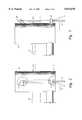
- FIG. 4shows a mounting porch subassembly for mounting a top end portion of a tendon to the hull of the floating marine platform shown in FIG. 1;
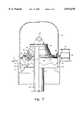
- FIG. 5is a schematic diagram, in partial section, showing a tension adjustment mechanism according to the present invention.
- FIG. 6is a schematic diagram similar to FIG. 5 but showing the tension adjustment mechanism during an intermediate step in an adjustment process
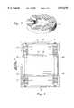
- FIG. 7is an isometric view of a lower adjusting ring in the tension adjustment mechanism of FIGS. 5 and 6;
- FIG. 8is a plan view of a motor and slide arrangement depicted schematically in FIGS. 5 and 6;
- FIG. 9is an end view of the motor and slide assembly introduced in FIG. 8.
- FIG. 1 of the drawingsthere is shown a floating marine platform 10 of the kind used for deep-water offshore drilling.
- the floating marine platform 10is anchored to a foundation generally designated 12 on the seabed 11.
- generally vertical tendons 13, 14depend from the platform to anchors 15, 16 in the foundation 12 on the seabed 11.
- Laterally extending mooring lines 17, 18depend from the platform 10 to anchors (not shown) on the seabed 11 in order to constrain horizontal movement of the platform 10 as would be caused by currents and wind.
- the platform 10includes a deck 19 on a hull 20.
- the deck 19is above the water line 21, and the hull 20 is partially above and partially below the water line.
- a drill stringFor drilling, a drill string depends from a derrick 22 on the deck 19 to a well bore 23 in the seabed 11. A portion of the drill string 24 called a "riser” depends from the derrick 22 to a wellhead 25 on the seabed 11.
- tendons 13, 14are shown in FIG. 1, it should be appreciated that for large platforms more than a dozen tendons may be used.
- a platform known as "Heidrun”is presently being deployed in 345 meters of water in the North Sea. This platform uses a system of 16 tendons for anchoring to the seabed. Each tendon is designed for a maximum tensile load of about 48 million newtons.
- the present inventionrelates more particularly to a tension adjustment mechanism located at the connection of a top end portion of each tendon 13, 14. It is desirable for the tension adjustment mechanism at the upper end of each tendon to be located above the water line 21. Due to horizontal movement of the platform, however, there should in addition be a relatively flexible mounting of each tendon at a lower most location on the hull 20, in order to prevent the tendon from being snapped by impact with the lowermost portion of the hull. In practice, this has been done by either running the tendon up through the middle of a column of the hull, or mounting the upper portion of the tendon to the outside of a column of the hull.
- the tendon 31depends from a top end termination 32 mounted to the hull column 33 at a location above the water line 34. Near the bottom of the hull column 33, the tendon 31 passes through a cross load bearing 35 mounted to the column.
- the cross load bearing 35permits relatively free axial movement of the tendon 31 but constrains transverse movement.
- the cross load bearing 35also permits angular deflection of the portion of the tendon depending from the hull member 33; for example, the tendon may deflect to a position 36 shown in phantom lines.
- the cross load bearing 35includes a flexible elastomeric joint surrounded by a radial elastomeric bearing.
- a flexible elastomeric jointis described, for example, in Whightsil, Sr., et al. U.S. Pat. No. 5,133,578, issued Jul. 28, 1992, and incorporated herein by reference.
- Suitable cross load bearingsare manufactured and sold by Oil States Industries, P.O. Box 670, Arlington, Tex. 76004.
- FIG. 3The case of a mounting of the upper portion of a tendon 41 to the side of a hull column 42 is shown in FIG. 3.
- the top end connection 43is mounted to the side of the hull column 42 above the water line 44, and a cross load bearing 46 is mounted to the side of the hull column below the water line 44 and near the bottom of the hull column.
- the top end connection 32 in FIG. 2 or 43 in FIG. 3includes a mooring porch subassembly fixed to the hull column.
- a suitable mooring porch subassemblygenerally designated 50.
- the mooring porch subassembly 50transmits the tension in the tendon (not shown) to the hull.
- the mooring porchis a weldment consisting of a forged, machined load ring 51 and a number of plates 52, 53.
- the plates 52, 53, performing as webs and flanges,serve to stabilize the load ring 51 as well as bridge loads between the hull (not shown) and the tendon (not shown).
- the rear portion of the mooring ring 50is welded or otherwise secured to the hull, and the tendon is inserted into load ring 51.
- the mooring porch 50may include a front slot generally designated 54 for ease of side entry of the tendon during installation.
- the mooring ring 50is similar to a conventional mooring ring except provision is made for mounting of an adjustment motor 96 shown in FIGS. 5 to 6 and 8 to 9 described below.
- the upper plate 52 of the mooring porch 50has four holes generally designated 55 for mounting of the motor to the mooring porch subassembly.
- the upper plate 52includes a number of additional holes 56 to 59 for termination of electrical cables (not shown) for cathodic protection.
- FIG. 5the tensioning adjustment mechanism according to the present invention is shown in partial section.
- an adjustable load ring assemblyincluding an upper ring 61 and a lower ring 62.
- Seated in the upper ring 61is an elastomeric flex joint bearing 63 supporting a top end 64 of a tendon generally designated 65.
- a clamping ring 66is secured by bolts 67 to the upper ring 61 so that the elastomeric flex bearing 63 is secured to the upper ring 61.
- the upper and lower load rings 61, 62, and the other metallic components in FIG. 6,are preferably made of steel, stainless steel, or titanium, depending on desired corrosion resistance and weight requirements.
- the elastomeric flex bearing 63is a conventional quasi-spherical elastomeric bearing and includes two metal rings separated by elastomer such as rubber, and annular metal laminations are embedded in the elastomer.
- An elastomeric flex bearing for supporting a maximum axial load of 48 million newtons, for example,has a height of about 56 cm, an inner diameter of about 70 cm, and an outer diameter of about 170 cm.
- Such an elastomeric flex bearing 63is manufactured and sold by Oil States Industries, P.O. Box 670, Arlington, Tex. 76004.
- the tendon 65is comprised mainly of a metal pipe terminated at its upper end by a cap 68 having an eye ring 69 for hoisting of the tendon.
- the end capseals the metal pipe of the tendon 65 for neutral buoyancy.
- the adjustable load ring assembly 61, 62, the elastomeric flex bearing 63, and the upper portion of the tendon 65are protected from salt spray by a corrosion cap 70 fastened to the upper rim of the mooring porch load ring 51.
- the adjustable load ring assembly 61, 62adjusts tension in the tendon by an angular displacement of the upper load ring 61 with respect to the lower load ring 62.
- the upper and lower rings 61, 62abut each other at a series of stepped inclines or serrated circumferential ramps 81.
- the entire series of rampsis shown in the isometric view of FIG. 7.
- eight separate ramps or staircaseseach having an identical shape and height, are uniformly distributed about the circumference of the lower load ring 62.
- Each ramp or staircasehas five serrations or steps.
- the lower surface of the upper ring 61is complementary to the upper surface of the lower ring 62.
- each of the serrations or stepshas a similar shape.
- the upper ring 61can index with the lower ring 62 so that the serrations or steps can align to provide five distinct values of vertical displacement of the upper ring 61 with respect to the lower ring 62.
- the tension in the tendonlocks the load rings together preventing relative angular displacement of the rings with respect to each other and, therefore, locking the tension adjustment.
- FIG. 6An intermediate step in the adjustment procedure is shown in FIG. 6.
- a comparison of FIG. 5 to FIG. 6shows that the position of the tendon 65 is relatively unchanged but the mooring porch load ring 51 has been depressed considerably by deballasting of the hull.
- the hullhas been sufficiently deballasted so that the upper surface 91 of the elastomeric flex bearing 63 is substantially spaced from the lower mating surface 92 of the upper portion of the tendon 65. Due to this spacing, the tendon 65 no longer applies a tension force onto the adjustable load ring assembly 61, 62 so that the upper load ring 61 can be rotated easily with respect to the lower load ring 62 in order to perform a tension adjustment.
- the desired amount of adjustment for the tendonis determined by the amount of tension present in the original configuration of FIG. 5.
- a series of force transducers 93are built into the elastomeric flex bearing 63. Therefore, in the original configuration of FIG. 5, the respective tensile force in each tendon can be measured, and from the collection of measurements and the spring constant of the elastomeric flex joint 63, a vertical displacement value can be computed for equalizing the tension on the tendons.
- This desired value of vertical displacementis then obtained by a selected amount of angular displacement of the upper and lower load rings 61, 62 with respect to each other. In the example of FIG. 6, for example, it has been determined that the desired vertical displacement corresponds to two serrations or steps in the staircases 81.
- a circumferential bevel gear 94is attached to the upper circumference of the upper load ring 61.
- the circumferential bevel gear 94mates with a bevel gear pinion 95 mounted on the shaft of a motor 96.
- the circumferential bevel gear 94need not extend a full circumference about the tendon 65, because a full range of tension adjustment can be obtained over a fraction of a full circumference. For example, for the case of eight staircases or ramps over a full circumference, a full range of tension adjustment can be obtained with a 45 degree range of angular displacement between the upper load ring 61 and the lower load ring 62.
- the motor 96is mounted to the upper plate 52 of the mooring porch via a slide mechanism 97 which is schematically shown in FIGS. 5 and 6 and is shown in further detail in FIGS. 8 and 9.
- the slides of the slide mechanism 97permit the motor 96 to move vertically with respect to the mooring porch as the vertical displacement is adjusted between the upper load ring 61 and the lower load ring 62.
- the motor 96for example, is a pneumatic or electric motor, and has internal speed reduction gearing to provide a relatively high amount of torque.
- FIG. 8there is shown a front view of the motor 96 and slide assembly 97.
- the slide assemblyincludes two vertical parallel spaced slide rods 101 and 102 that span a top plate 103 and a bottom plate 104.
- the motor 96is fastened to a carriage 105 having four bearings 106, 107, 108, 109 which engage the respective slides 101 and 102.
- the slides 101, 102are enclosed by respective rubber bellows 110, 111, 112, and 113.
- the top plate 103 and the bottom plate 104are joined by a back plate 114 and bracing plates 115, 116, and 117.
- the motor carriage 105includes a pipe 118 protecting the portion of the guide rod 101 that is spanned by the motor carriage.
- split load rings 61, 62are more compact, lighter, and less costly to manufacture than the tie-off nut, load adjustment ring, and adjustment shaft used in a conventional adjustment mechanism.
- Another alternative constructioncould rotate the lower load ring 62 with a fixed motor and use a spline or keyway between the upper load ring 61 and the mooring porch load ring 51 to prevent rotation of the upper load ring 61 with respect to the mooring porch load ring 51.
- the granularity of the tension adjustmentis determined by the vertical size of the steps or serrations in the abutting complementary surfaces of the upper load ring 61 and lower load ring 62. Although this granularity can be reduced to a practical level by increasing the number of steps in each ramp, it would also be possible to stack three or more adjustable load rings, instead of two, in order to further decrease the granularity of the tension adjustment.
- abutting complementary surfaces between first and second lower adjustable load ringscould have at least ten one-millimeter high steps per ramp
- abutting complementary surfaces between the second adjustable load ring and a third and upper adjustable load ringcould have at least ten one-centimeter high steps per ramp.
- the vertical distance between the first and third adjustable load ringscould be adjusted to any value from 0 mm to 99 mm, in one mm increments, by rotating the second adjustable load ring with respect to the first adjustable load ring to select a millimeter digit value of the vertical distance, and rotating the third adjustable load ring with respect to the second adjustable load ring to select a centimeter digit value of the vertical distance.
Landscapes
- Engineering & Computer Science (AREA)
- Structural Engineering (AREA)
- Life Sciences & Earth Sciences (AREA)
- General Life Sciences & Earth Sciences (AREA)
- Mining & Mineral Resources (AREA)
- Paleontology (AREA)
- Civil Engineering (AREA)
- General Engineering & Computer Science (AREA)
- Bridges Or Land Bridges (AREA)
Abstract
Description
Claims (23)
Priority Applications (1)
| Application Number | Priority Date | Filing Date | Title |
|---|---|---|---|
| US08/780,059US5873678A (en) | 1996-12-23 | 1996-12-23 | Tension adjustment mechanism employing stepped or serrated ramps for adjusting tension of a tendon from a floating marine platform |
Applications Claiming Priority (1)
| Application Number | Priority Date | Filing Date | Title |
|---|---|---|---|
| US08/780,059US5873678A (en) | 1996-12-23 | 1996-12-23 | Tension adjustment mechanism employing stepped or serrated ramps for adjusting tension of a tendon from a floating marine platform |
Publications (1)
| Publication Number | Publication Date |
|---|---|
| US5873678Atrue US5873678A (en) | 1999-02-23 |
Family
ID=25118449
Family Applications (1)
| Application Number | Title | Priority Date | Filing Date |
|---|---|---|---|
| US08/780,059Expired - Fee RelatedUS5873678A (en) | 1996-12-23 | 1996-12-23 | Tension adjustment mechanism employing stepped or serrated ramps for adjusting tension of a tendon from a floating marine platform |
Country Status (1)
| Country | Link |
|---|---|
| US (1) | US5873678A (en) |
Cited By (13)
| Publication number | Priority date | Publication date | Assignee | Title |
|---|---|---|---|---|
| US6190091B1 (en)* | 1997-08-26 | 2001-02-20 | Novellent Technologies Llc | Tension control device for tensile elements |
| US6688814B2 (en)* | 2001-09-14 | 2004-02-10 | Union Oil Company Of California | Adjustable rigid riser connector |
| WO2006038091A3 (en)* | 2004-10-06 | 2006-06-22 | Enertec Ag | Construction of a submerged floating foundation |
| US20070063507A1 (en)* | 2005-09-19 | 2007-03-22 | Vetco Gray Inc. | System, method, and apparatus for a radially-movable line termination system for a riser string on a drilling rig |
| US20070201955A1 (en)* | 2006-02-24 | 2007-08-30 | Technip France | Hull-to-caisson interface connection assembly for spar platform |
| US20080085165A1 (en)* | 2005-03-29 | 2008-04-10 | Vladimir Volokh | Method for making by assembling a tool to and in a tool holder, and the tool and tool holder, and the assembled tool and tool holder |
| US20090290939A1 (en)* | 2008-05-21 | 2009-11-26 | Edward Sean Large | Method and apparatus for restraining a tendon top connector in reverse loading conditions |
| US7886828B1 (en)* | 2008-09-02 | 2011-02-15 | Atp Oil & Gas Corporation | Floating vessel for supporting top tension drilling and production risers |
| US20110318140A1 (en)* | 2010-06-24 | 2011-12-29 | Wen-Yao Chang | Height adjustment ring spacer |
| PT107606A (en)* | 2014-04-25 | 2015-10-26 | Miguel Marinho Mendes Abreu | FLOATING PLATFORM STABILIZED BY TENSIONED MOORINGS FOR WIND ENERGY GENERATOR WITH ARMED CONCRETE FLOATERS AND VISIBLE MOORING CHAMBER |
| WO2016123236A1 (en)* | 2015-01-27 | 2016-08-04 | Seahorse Equipment Corp | Method and apparatus for replacing a tendon flex bearing on a tension leg platform |
| WO2017050841A1 (en)* | 2015-09-25 | 2017-03-30 | Single Buoy Moorings Inc. | Connector arrangement for connecting a mooring line to a floating structure and floating structure comprising such a connector arrangement |
| US20170166285A1 (en)* | 2014-04-07 | 2017-06-15 | Techlam Sas | Anchoring line for a floating base, comprising an elastic device |
Citations (40)
| Publication number | Priority date | Publication date | Assignee | Title |
|---|---|---|---|---|
| US1386317A (en)* | 1921-03-24 | 1921-08-02 | William A Claassen | Adjustable caster |
| US1940278A (en)* | 1931-08-14 | 1933-12-19 | Barnes Corning Company | Form clamp |
| US2405889A (en)* | 1943-11-16 | 1946-08-13 | Saco Lowell Shops | Spindle adjusting device |
| US3602000A (en)* | 1969-09-19 | 1971-08-31 | Homayoun Joe Meheen | Reinforced steel pipe piling structure |
| US4320993A (en)* | 1980-07-28 | 1982-03-23 | Conoco Inc. | Tension leg platform mooring tether connector |
| US4324194A (en)* | 1976-12-10 | 1982-04-13 | Hydra-Rig, Inc. | Stabilized hoist rig for deep ocean mining vessel |
| US4333725A (en)* | 1977-04-25 | 1982-06-08 | Conoco Inc. | Compression stressed weld joints on offshore platforms |
| US4359960A (en)* | 1980-01-30 | 1982-11-23 | Vickers Limited | Marine tether anchoring device |
| US4364323A (en)* | 1980-01-26 | 1982-12-21 | Vickers Limited | Vertical stressed mooring tether in a floating oil platform |
| US4374630A (en)* | 1980-08-21 | 1983-02-22 | Vetco Offshore, Inc. | Anchor connector for tension leg |
| US4379657A (en)* | 1980-06-19 | 1983-04-12 | Conoco Inc. | Riser tensioner |
| US4391554A (en)* | 1980-08-22 | 1983-07-05 | Vetco Offshore, Inc. | Mooring system bearing for a tensioned leg platform |
| US4400112A (en)* | 1981-01-13 | 1983-08-23 | Societe Nationale Elf Aquitaine (Production) | Connecting and disconnecting device for a guide line |
| US4432670A (en)* | 1980-10-01 | 1984-02-21 | Armco Inc. | Combination connector and flex joint for underwater tension elements |
| US4433879A (en)* | 1981-04-02 | 1984-02-28 | Morris James C | Adjustable extension-cam shim |
| US4439055A (en)* | 1982-01-25 | 1984-03-27 | Vetco Offshore, Inc. | Anchor connector |
| US4459933A (en)* | 1980-11-06 | 1984-07-17 | Vickers Limited | Marine tether anchoring device |
| US4516882A (en)* | 1982-06-11 | 1985-05-14 | Fluor Subsea Services, Inc. | Method and apparatus for conversion of semi-submersible platform to tension leg platform for conducting offshore well operations |
| US4585369A (en)* | 1983-12-01 | 1986-04-29 | Alsthom-Atlantique | Mechanical connection means |
| US4611953A (en)* | 1985-11-01 | 1986-09-16 | Vetco Offshore Industries, Inc. | TLP tendon bottom connector |
| US4640487A (en)* | 1984-04-17 | 1987-02-03 | Salter Anthony J | Pipe supports |
| US4746247A (en)* | 1987-01-30 | 1988-05-24 | Lockheed Corporation | Stabilizing ring for interlocking load ring/back flange interface |
| US4759662A (en)* | 1986-06-30 | 1988-07-26 | Lockheed Corporation | TLP marine riser tensioner |
| US4784529A (en)* | 1987-10-06 | 1988-11-15 | Conoco Inc. | Mooring apparatus and method of installation for deep water tension leg platform |
| US4871282A (en)* | 1987-12-30 | 1989-10-03 | Vetco Gray Inc. | Tension leg platform tendon top connector |
| US4881852A (en)* | 1988-01-22 | 1989-11-21 | Exxon Production Research Company | Method and apparatus for tensioning the tethers of a tension leg platform |
| US4883387A (en)* | 1987-04-24 | 1989-11-28 | Conoco, Inc. | Apparatus for tensioning a riser |
| US4892444A (en)* | 1987-02-24 | 1990-01-09 | Dunlop Limited A British Company | Resilient unit |
| US4907914A (en)* | 1987-05-11 | 1990-03-13 | Exxon Production Research Company | Tether connector for a tension leg platform |
| US5054963A (en)* | 1988-09-29 | 1991-10-08 | Gotaverken Arendal Ab | Tether system for an offshore based work platform |
| US5133578A (en)* | 1991-03-08 | 1992-07-28 | Ltv Energy Products Company | Flexible joint with non-diffusive barrier |
| US5160219A (en)* | 1991-01-15 | 1992-11-03 | Ltv Energy Products Company | Variable spring rate riser tensioner system |
| US5240076A (en)* | 1990-01-18 | 1993-08-31 | Abb Vetco Gray Inc. | Casing tension retainer |
| US5255746A (en)* | 1992-08-06 | 1993-10-26 | Abb Vetco Gray Inc. | Adjustable mandrel hanger assembly |
| US5310007A (en)* | 1993-04-09 | 1994-05-10 | Paul Munore Engineering International | Tensioning ring and riser assembly for an oil well platform tensioning apparatus |
| US5324141A (en)* | 1987-10-06 | 1994-06-28 | Conoco Inc. | Mooring apparatus and method of installation for deep water tension leg platform |
| US5363920A (en)* | 1993-03-05 | 1994-11-15 | Westinghouse Electric Corporation | Elastomeric passive tensioner for oil well risers |
| US5366324A (en)* | 1990-12-13 | 1994-11-22 | Ltv Energy Products Co. | Riser tensioner system for use on offshore platforms using elastomeric pads or helical metal compression springs |
| US5431511A (en)* | 1992-11-26 | 1995-07-11 | Kvaerner Earl And Wright | Tension leg platform |
| US5482406A (en)* | 1993-04-15 | 1996-01-09 | Continental Emsco Company | Variable spring rate compression element and riser tensioner system using the same |
- 1996
- 1996-12-23USUS08/780,059patent/US5873678A/ennot_activeExpired - Fee Related
Patent Citations (41)
| Publication number | Priority date | Publication date | Assignee | Title |
|---|---|---|---|---|
| US1386317A (en)* | 1921-03-24 | 1921-08-02 | William A Claassen | Adjustable caster |
| US1940278A (en)* | 1931-08-14 | 1933-12-19 | Barnes Corning Company | Form clamp |
| US2405889A (en)* | 1943-11-16 | 1946-08-13 | Saco Lowell Shops | Spindle adjusting device |
| US3602000A (en)* | 1969-09-19 | 1971-08-31 | Homayoun Joe Meheen | Reinforced steel pipe piling structure |
| US4324194A (en)* | 1976-12-10 | 1982-04-13 | Hydra-Rig, Inc. | Stabilized hoist rig for deep ocean mining vessel |
| US4333725A (en)* | 1977-04-25 | 1982-06-08 | Conoco Inc. | Compression stressed weld joints on offshore platforms |
| US4364323A (en)* | 1980-01-26 | 1982-12-21 | Vickers Limited | Vertical stressed mooring tether in a floating oil platform |
| USRE32384E (en)* | 1980-01-30 | 1987-03-31 | Vickers Public Limited Company | Marine tether anchoring device |
| US4359960A (en)* | 1980-01-30 | 1982-11-23 | Vickers Limited | Marine tether anchoring device |
| US4379657A (en)* | 1980-06-19 | 1983-04-12 | Conoco Inc. | Riser tensioner |
| US4320993A (en)* | 1980-07-28 | 1982-03-23 | Conoco Inc. | Tension leg platform mooring tether connector |
| US4374630A (en)* | 1980-08-21 | 1983-02-22 | Vetco Offshore, Inc. | Anchor connector for tension leg |
| US4391554A (en)* | 1980-08-22 | 1983-07-05 | Vetco Offshore, Inc. | Mooring system bearing for a tensioned leg platform |
| US4432670A (en)* | 1980-10-01 | 1984-02-21 | Armco Inc. | Combination connector and flex joint for underwater tension elements |
| US4459933A (en)* | 1980-11-06 | 1984-07-17 | Vickers Limited | Marine tether anchoring device |
| US4400112A (en)* | 1981-01-13 | 1983-08-23 | Societe Nationale Elf Aquitaine (Production) | Connecting and disconnecting device for a guide line |
| US4433879A (en)* | 1981-04-02 | 1984-02-28 | Morris James C | Adjustable extension-cam shim |
| US4439055A (en)* | 1982-01-25 | 1984-03-27 | Vetco Offshore, Inc. | Anchor connector |
| US4516882A (en)* | 1982-06-11 | 1985-05-14 | Fluor Subsea Services, Inc. | Method and apparatus for conversion of semi-submersible platform to tension leg platform for conducting offshore well operations |
| US4585369A (en)* | 1983-12-01 | 1986-04-29 | Alsthom-Atlantique | Mechanical connection means |
| US4640487A (en)* | 1984-04-17 | 1987-02-03 | Salter Anthony J | Pipe supports |
| US4611953A (en)* | 1985-11-01 | 1986-09-16 | Vetco Offshore Industries, Inc. | TLP tendon bottom connector |
| US4759662A (en)* | 1986-06-30 | 1988-07-26 | Lockheed Corporation | TLP marine riser tensioner |
| US4746247A (en)* | 1987-01-30 | 1988-05-24 | Lockheed Corporation | Stabilizing ring for interlocking load ring/back flange interface |
| US4892444A (en)* | 1987-02-24 | 1990-01-09 | Dunlop Limited A British Company | Resilient unit |
| US4883387A (en)* | 1987-04-24 | 1989-11-28 | Conoco, Inc. | Apparatus for tensioning a riser |
| US4907914A (en)* | 1987-05-11 | 1990-03-13 | Exxon Production Research Company | Tether connector for a tension leg platform |
| US5324141A (en)* | 1987-10-06 | 1994-06-28 | Conoco Inc. | Mooring apparatus and method of installation for deep water tension leg platform |
| US4784529A (en)* | 1987-10-06 | 1988-11-15 | Conoco Inc. | Mooring apparatus and method of installation for deep water tension leg platform |
| US4871282A (en)* | 1987-12-30 | 1989-10-03 | Vetco Gray Inc. | Tension leg platform tendon top connector |
| US4881852A (en)* | 1988-01-22 | 1989-11-21 | Exxon Production Research Company | Method and apparatus for tensioning the tethers of a tension leg platform |
| US5054963A (en)* | 1988-09-29 | 1991-10-08 | Gotaverken Arendal Ab | Tether system for an offshore based work platform |
| US5240076A (en)* | 1990-01-18 | 1993-08-31 | Abb Vetco Gray Inc. | Casing tension retainer |
| US5366324A (en)* | 1990-12-13 | 1994-11-22 | Ltv Energy Products Co. | Riser tensioner system for use on offshore platforms using elastomeric pads or helical metal compression springs |
| US5160219A (en)* | 1991-01-15 | 1992-11-03 | Ltv Energy Products Company | Variable spring rate riser tensioner system |
| US5133578A (en)* | 1991-03-08 | 1992-07-28 | Ltv Energy Products Company | Flexible joint with non-diffusive barrier |
| US5255746A (en)* | 1992-08-06 | 1993-10-26 | Abb Vetco Gray Inc. | Adjustable mandrel hanger assembly |
| US5431511A (en)* | 1992-11-26 | 1995-07-11 | Kvaerner Earl And Wright | Tension leg platform |
| US5363920A (en)* | 1993-03-05 | 1994-11-15 | Westinghouse Electric Corporation | Elastomeric passive tensioner for oil well risers |
| US5310007A (en)* | 1993-04-09 | 1994-05-10 | Paul Munore Engineering International | Tensioning ring and riser assembly for an oil well platform tensioning apparatus |
| US5482406A (en)* | 1993-04-15 | 1996-01-09 | Continental Emsco Company | Variable spring rate compression element and riser tensioner system using the same |
Non-Patent Citations (4)
| Title |
|---|
| "Oil States Industries Flex Joints for TLP Mooring Systems, Drilling and Production Risers," Continental Emsco Company, 1994, Arlington, Texas, 6 pages. |
| Oil States Industries Flex Joints for TLP Mooring Systems, Drilling and Production Risers, Continental Emsco Company, 1994, Arlington, Texas, 6 pages.* |
| Oil States Industries, drawings, "TCA Components", Mooring Porch Subassembly (Undated). |
| Oil States Industries, drawings, TCA Components , Mooring Porch Subassembly (Undated).* |
Cited By (22)
| Publication number | Priority date | Publication date | Assignee | Title |
|---|---|---|---|---|
| US6190091B1 (en)* | 1997-08-26 | 2001-02-20 | Novellent Technologies Llc | Tension control device for tensile elements |
| US6688814B2 (en)* | 2001-09-14 | 2004-02-10 | Union Oil Company Of California | Adjustable rigid riser connector |
| US20100150664A1 (en)* | 2004-10-06 | 2010-06-17 | Enertec Ag | Submerged floating foundation with blocked vertical thrust as support base for wind turbine, electrolyser and other equipment, combined with fish farming |
| WO2006038091A3 (en)* | 2004-10-06 | 2006-06-22 | Enertec Ag | Construction of a submerged floating foundation |
| US8235629B2 (en) | 2004-10-06 | 2012-08-07 | Blue H Intellectual Property Cyprus Ltd. | Submerged floating foundation with blocked vertical thrust as support base for wind turbine, electrolyser and other equipment, combined with fish farming |
| CN101076634B (en)* | 2004-10-06 | 2011-03-23 | 恩纳泰克股份公司 | Equipment and method for mounting float base under the water vertically driving hindered |
| US20080085165A1 (en)* | 2005-03-29 | 2008-04-10 | Vladimir Volokh | Method for making by assembling a tool to and in a tool holder, and the tool and tool holder, and the assembled tool and tool holder |
| US8079790B2 (en) | 2005-03-29 | 2011-12-20 | Hanita Metal Works, Ltd. | Method for making by assembling a tool to and in a tool holder, and the tool and tool holder, and the assembled tool and tool holder |
| US7571772B2 (en)* | 2005-09-19 | 2009-08-11 | Vetco Gray Inc. | System, method, and apparatus for a radially-movable line termination system for a riser string on a drilling rig |
| US20070063507A1 (en)* | 2005-09-19 | 2007-03-22 | Vetco Gray Inc. | System, method, and apparatus for a radially-movable line termination system for a riser string on a drilling rig |
| EP1989395A2 (en)* | 2006-02-24 | 2008-11-12 | Technip France SA | Hull-to-caisson interface connection assembly for spar platform |
| US20070201955A1 (en)* | 2006-02-24 | 2007-08-30 | Technip France | Hull-to-caisson interface connection assembly for spar platform |
| US7559723B2 (en)* | 2006-02-24 | 2009-07-14 | Technip France | Hull-to-caisson interface connection assembly for spar platform |
| US7914234B2 (en)* | 2008-05-21 | 2011-03-29 | Seahorse Equipment Corporation | Method and apparatus for restraining a tendon top connector in reverse loading conditions |
| US20090290939A1 (en)* | 2008-05-21 | 2009-11-26 | Edward Sean Large | Method and apparatus for restraining a tendon top connector in reverse loading conditions |
| US7886828B1 (en)* | 2008-09-02 | 2011-02-15 | Atp Oil & Gas Corporation | Floating vessel for supporting top tension drilling and production risers |
| US20110318140A1 (en)* | 2010-06-24 | 2011-12-29 | Wen-Yao Chang | Height adjustment ring spacer |
| US20170166285A1 (en)* | 2014-04-07 | 2017-06-15 | Techlam Sas | Anchoring line for a floating base, comprising an elastic device |
| US10065710B2 (en)* | 2014-04-07 | 2018-09-04 | IFP Energies Nouvelles | Anchoring line for a floating base, comprising an elastic device |
| PT107606A (en)* | 2014-04-25 | 2015-10-26 | Miguel Marinho Mendes Abreu | FLOATING PLATFORM STABILIZED BY TENSIONED MOORINGS FOR WIND ENERGY GENERATOR WITH ARMED CONCRETE FLOATERS AND VISIBLE MOORING CHAMBER |
| WO2016123236A1 (en)* | 2015-01-27 | 2016-08-04 | Seahorse Equipment Corp | Method and apparatus for replacing a tendon flex bearing on a tension leg platform |
| WO2017050841A1 (en)* | 2015-09-25 | 2017-03-30 | Single Buoy Moorings Inc. | Connector arrangement for connecting a mooring line to a floating structure and floating structure comprising such a connector arrangement |
Similar Documents
| Publication | Publication Date | Title |
|---|---|---|
| US5873678A (en) | Tension adjustment mechanism employing stepped or serrated ramps for adjusting tension of a tendon from a floating marine platform | |
| US5615977A (en) | Flexible/rigid riser system | |
| US6227137B1 (en) | Spar platform with spaced buoyancy | |
| US8083439B2 (en) | Riser support system for use with an offshore platform | |
| US6263824B1 (en) | Spar platform | |
| US7096940B2 (en) | Centralizer system for insulated pipe | |
| US6309141B1 (en) | Gap spar with ducking risers | |
| US20040253059A1 (en) | Multi-cellular floating platform with central riser buoy | |
| US5054415A (en) | Mooring/support system for marine structures | |
| US4127005A (en) | Riser/jacket vertical bearing assembly for vertically moored platform | |
| US7559723B2 (en) | Hull-to-caisson interface connection assembly for spar platform | |
| US20140205383A1 (en) | Jack-up drilling unit with tension legs | |
| CA1307171C (en) | Mooring apparatus and method of installation for deep water tension leg platform | |
| US5873395A (en) | Method for mooring floating storage vessels | |
| US20040182297A1 (en) | Riser pipe support system and method | |
| IE54320B1 (en) | An articulated pipe discharge ramp and a method for laying a pipeline | |
| WO2009101378A1 (en) | Apparatus for protecting a riser string | |
| US8813670B2 (en) | Floating structure | |
| US6688250B2 (en) | Method and apparatus for reducing tension variations in mono-column TLP systems | |
| US4881852A (en) | Method and apparatus for tensioning the tethers of a tension leg platform | |
| US4818147A (en) | Tendon for anchoring a semisubmersible platform | |
| US4780026A (en) | Tension leg platform and installation method therefor | |
| EP0235262B1 (en) | Fatigue resistant coupling for tubular members | |
| US5775845A (en) | Passive riser tensioner | |
| EP0045651B1 (en) | Apparatus and method for supporting a tubular riser |
Legal Events
| Date | Code | Title | Description |
|---|---|---|---|
| AS | Assignment | Owner name:CONTINENTAL EMSCO COMPANY, TEXAS Free format text:ASSIGNMENT OF ASSIGNORS INTEREST;ASSIGNOR:MOSES, CHARLES J.;REEL/FRAME:008386/0509 Effective date:19961217 | |
| AS | Assignment | Owner name:OIL STATES INDUSRIES, INC., TEXAS Free format text:ASSIGNMENT OF ASSIGNORS INTEREST;ASSIGNOR:CONTINENTAL EMSCO COMPANY;REEL/FRAME:011170/0181 Effective date:20001002 | |
| AS | Assignment | Owner name:CREDIT SUISSE FIRST BOSTON, AS U.S. COLLATERAL AGE Free format text:SECURITY AGREEMENT;ASSIGNORS:OIL STATES;A-Z TERMINAL CORPORATION;CAPSTAR DRILLING, INC.;AND OTHERS;REEL/FRAME:011566/0720 Effective date:20010214 | |
| AS | Assignment | Owner name:OIL STATES INDUSTRIES, INC., TEXAS Free format text:MERGER/CHANGE OF NAME;ASSIGNOR:OIL STATES INDUSTRIES, INC.;REEL/FRAME:012641/0475 Effective date:20011231 | |
| FPAY | Fee payment | Year of fee payment:4 | |
| AS | Assignment | Owner name:WELLS FARGO BANK OF TEXAS, TEXAS Free format text:SECURITY AGREEMENT;ASSIGNORS:OIL STATES INDUSTRIES, INC.;A-Z TERMINAL CORPORATION;CAPSTAR DRILLING, L.P.;AND OTHERS;REEL/FRAME:014709/0287 Effective date:20031031 | |
| FPAY | Fee payment | Year of fee payment:8 | |
| REMI | Maintenance fee reminder mailed | ||
| LAPS | Lapse for failure to pay maintenance fees | ||
| LAPS | Lapse for failure to pay maintenance fees | Free format text:PATENT EXPIRED FOR FAILURE TO PAY MAINTENANCE FEES (ORIGINAL EVENT CODE: EXP.); ENTITY STATUS OF PATENT OWNER: LARGE ENTITY | |
| STCH | Information on status: patent discontinuation | Free format text:PATENT EXPIRED DUE TO NONPAYMENT OF MAINTENANCE FEES UNDER 37 CFR 1.362 | |
| FP | Lapsed due to failure to pay maintenance fee | Effective date:20110223 |