US5872582A - Microfluid valve for modulating fluid flow within an ink-jet printer - Google Patents
Microfluid valve for modulating fluid flow within an ink-jet printerDownload PDFInfo
- Publication number
- US5872582A US5872582AUS08/675,366US67536696AUS5872582AUS 5872582 AUS5872582 AUS 5872582AUS 67536696 AUS67536696 AUS 67536696AUS 5872582 AUS5872582 AUS 5872582A
- Authority
- US
- United States
- Prior art keywords
- ink
- printhead
- channel
- valve member
- firing chamber
- Prior art date
- Legal status (The legal status is an assumption and is not a legal conclusion. Google has not performed a legal analysis and makes no representation as to the accuracy of the status listed.)
- Expired - Lifetime
Links
Images


Classifications
- B—PERFORMING OPERATIONS; TRANSPORTING
- B41—PRINTING; LINING MACHINES; TYPEWRITERS; STAMPS
- B41J—TYPEWRITERS; SELECTIVE PRINTING MECHANISMS, i.e. MECHANISMS PRINTING OTHERWISE THAN FROM A FORME; CORRECTION OF TYPOGRAPHICAL ERRORS
- B41J2/00—Typewriters or selective printing mechanisms characterised by the printing or marking process for which they are designed
- B41J2/005—Typewriters or selective printing mechanisms characterised by the printing or marking process for which they are designed characterised by bringing liquid or particles selectively into contact with a printing material
- B41J2/01—Ink jet
- B41J2/21—Ink jet for multi-colour printing
- B41J2/2107—Ink jet for multi-colour printing characterised by the ink properties
- B41J2/211—Mixing of inks, solvent or air prior to paper contact
- B—PERFORMING OPERATIONS; TRANSPORTING
- B41—PRINTING; LINING MACHINES; TYPEWRITERS; STAMPS
- B41J—TYPEWRITERS; SELECTIVE PRINTING MECHANISMS, i.e. MECHANISMS PRINTING OTHERWISE THAN FROM A FORME; CORRECTION OF TYPOGRAPHICAL ERRORS
- B41J2/00—Typewriters or selective printing mechanisms characterised by the printing or marking process for which they are designed
- B41J2/005—Typewriters or selective printing mechanisms characterised by the printing or marking process for which they are designed characterised by bringing liquid or particles selectively into contact with a printing material
- B41J2/01—Ink jet
- B41J2/015—Ink jet characterised by the jet generation process
- B41J2/04—Ink jet characterised by the jet generation process generating single droplets or particles on demand
- B41J2/045—Ink jet characterised by the jet generation process generating single droplets or particles on demand by pressure, e.g. electromechanical transducers
- B41J2/055—Devices for absorbing or preventing back-pressure
- B—PERFORMING OPERATIONS; TRANSPORTING
- B41—PRINTING; LINING MACHINES; TYPEWRITERS; STAMPS
- B41J—TYPEWRITERS; SELECTIVE PRINTING MECHANISMS, i.e. MECHANISMS PRINTING OTHERWISE THAN FROM A FORME; CORRECTION OF TYPOGRAPHICAL ERRORS
- B41J2/00—Typewriters or selective printing mechanisms characterised by the printing or marking process for which they are designed
- B41J2/005—Typewriters or selective printing mechanisms characterised by the printing or marking process for which they are designed characterised by bringing liquid or particles selectively into contact with a printing material
- B41J2/01—Ink jet
- B41J2/135—Nozzles
- B41J2/14—Structure thereof only for on-demand ink jet heads
- B41J2/14016—Structure of bubble jet print heads
- B41J2/14032—Structure of the pressure chamber
- B41J2/14048—Movable member in the chamber
Definitions
- the present inventionrelates to a device for controlling fluid flow and pressure within an ink-jet printhead.
- An ink-jet printerincludes a pen in which small droplets of ink are formed and ejected toward a printing medium.
- the penis mounted to a reciprocating carriage in the printer.
- Such pensinclude printheads with orifice plates having very small nozzles through which ink droplets are ejected.
- Adjacent to the nozzlesare ink chambers where ink is stored prior to ejection.
- Inkis delivered to the ink chambers through ink channels that are in fluid communication with an ink supply.
- the ink supplymay be, for example, contained in a reservoir section of the pen or supplied to the pen from a remote site.
- Ejection of an ink droplet through a nozzlemay be accomplished by quickly heating a volume of ink within the adjacent ink chamber.
- the thermal processcauses ink within the chamber to superheat and form a vapor bubble. Formation of a thermal ink-jet vapor bubble is known as "nucleation.”
- the rapid expansion of ink vaporforces a drop of ink through the orifice. This process is called “firing.”
- Ink in the chambermay be heated, for example, with a resistor that is responsive to a control signal. The resistor is aligned adjacent the nozzle.
- Ink-jet printheadstypically rely on capillary forces to draw ink through the ink channels to the ink chambers.
- back pressuremeans a partial vacuum within the printhead. Back pressure is considered in the positive sense, so that an increase in back pressure represents an increase in the partial vacuum.
- the capillary forcesovercome a slightly positive back pressure created by a regulator. Once ink is ejected from the chamber, the chamber is refilled by the capillary force, readying the system for firing another droplet.
- the inertia of the moving inkcauses some of the ink to bulge out of the orifice. Because ink within the pen is generally kept at a slightly positive back pressure, the bulging portion of the ink immediately recoils back into the ink chamber. This reciprocating motion diminishes over a few cycles and eventually stops or damps out.
- the ejected dropletwill be dumbbell shaped and slow moving. Conversely, if the ink is ejected when ink is recoiling from the nozzle, the ejected droplet will be spear shaped and move undesirably fast. Between these two extremes, as the ink motion damps out in the chamber, well-formed drops are produced for optimum print quality.
- Print speed(that is, the rate at which droplets are ejected) must be sufficiently slow to allow the ink motion within the chamber to damp out between droplet firing.
- the time period required for the ink motion to damp sufficientlymay be referred to as the damping interval.
- ink chamber geometryhas been manipulated.
- the chambersare constricted in a way that reduces the ink chamber refill speed in an effort to rapidly damp the bulging, refilling ink.
- chamber length and areaare constructed to lessen the reciprocating motion of chamber refill ink (hence, lessen the damping interval).
- printheadshave been unable to eliminate the damping interval.
- print speedmust accommodate the damping interval, or print and image quality suffer.
- Ink-jet printheadsare also susceptible to ink "blowback" during droplet ejection.
- Blowbackresults when some ink in the chamber is forced back into the adjacent part of the channel upon firing. Blowback occurs because the chamber is in constant fluid communication with the channel, hence, upon firing, a large portion of ink within the chamber is not ejected from the printhead, but rather is blown back into the channel.
- Blowbackwastes some energy that is for ejection of droplets from the chamber ("turn on energy" or TOE) because only a portion of the entire volume of ink in the chamber is actually ejected.
- TOEturn on energy
- reducing blowbackreduces TOE to increase the thermal efficiency of an ink-jet pen.
- higher TOEresults in excessive printhead heating. Excessive printhead heating generates bubbles from air dissolved in the ink, causing prenucleation of the ink vapor bubble. Air bubbles and prenucleation result in poor print quality.
- the present inventionprovides a system for controlling fluid flow and fluid pressure within an ink-jet printhead.
- fluid flow and pressure within the printheadis controlled by a passive valve device affixed to or integral with a printhead of an ink-jet pen.
- the valve deviceincludes at least one minute, passive valve member.
- the valve membercomprises a resiliently deformable flap positioned in the ink channel adjacent to a firing chamber.
- the flapis deflectable into and out of a position to regulate ink flow and pressure both to and from the ink firing chambers.
- the valve memberis deformable into a position that substantially isolates the ink chamber from the channel during firing of an ink droplet. Such isolation of the ink chamber reduces ink blowback. During ejection, ink in the chamber is blocked by the deformed valve member and cannot blowback into the ink channel, but must exit through the nozzle. Reducing ink blowback furthers regulation of fluid pressure within the pen and reduces TOE.
- the ink chamberis isolated immediately after the ink chamber is refilled thereby reducing the ink damping interval. That is, with an isolated ink chamber, the distance bulging ink may recoil back from the nozzle is limited, reducing the reciprocating motion of ink.
- the present inventionmay be micromachined, providing low cost, wafer-based batch processing and repeatability.
- Fig. 1is perspective view of an ink-jet printer pen that includes a preferred embodiment of the printhead valve device.
- FIG. 2stan enlarged cross-sectional partial view of a preferred embodiment of the device of the present invention.
- FIG. 3is an enlarged cross-sectional partial view of another preferred embodiment of the valve device of the present invention.
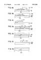
- FIGS. 4a-4cdepict the sequence of steps for fabricating the embodiment of the present invent illustrated in FIG. 2.
- FIGS. 5a-5ddepict the sequence of steps for fabricating the embodiment of FIG. 3.
- FIGS. 6a-6bare enlarged, cross-sectional, partial views of another embodiment of the present invention.
- FIG. 7is an enlarged cross-sectional partial view of another preferred embodiment of the valve device of the present invention.
- FIG. 8is an enlarged perspective view depicting fabrication of a preferred embodiment of the valve device by laser ablation.
- FIG. 9is an enlarged perspective view depicting fabrication of a preferred embodiment of the valve device by laser ablation.
- the valve device of the present inventionis incorporated within an ink-jet printer pen 10.
- the penincludes a pen body 12 defining a reservoir 24.
- the reservoir 24is configured to hold a quantity of ink.
- a printhead 20is fit into the bottom 14 of the pen body 12 and controlled for ejecting ink droplets from the reservoir 24.
- the printhead 20defines a set of nozzles 22 for expelling ink, in a controlled pattern, during printing. Each nozzle 22 is in fluid communication with a firing chamber defined in the base of printhead 20.
- a supply conduit(not shown) conducts ink from the reservoir 24 (FIG. 1) to ink channels 128a and 128b, defined by the printhead (FIG. 2).
- the ink channelsare configured so that ink moving therethrough is in fluid communication with each firing chamber 132 (FIG. 2).
- Each firing chamber 132has associated with it a thin-film resistor.
- the resistorsare selectively driven (heated) by current applied by an external microprocessor and associated drivers.
- Conductive drive lines to each resistorare carried upon a circuit 26 mounted to the exterior of the pen body 12 (FIG. 1).
- Circuit contact pads 18shown enlarged for illustration) at the ends of the resistor drive lines engage similar pads carried on a matching circuit attached to the carriage (not shown).
- Valve member 110is affixed within printhead 20 of ink-jet pen 10 (FIGS. 1 and 2). More particularly, valve member 110 is connected to or integral with the printhead ink channels 128a and 128b. The valve member is located between an ink supply and the firing chambers 132.
- the ink channels 128a and 128bdefine an upstream and downstream ink flow path, respectively, relative to the valve device.
- the ink channelscomprise a continuous pathway for ink flowing from an ink supply to the firing chamber. More particularly, an ink supply within the pen reservoir 24, or at a site remote of the pen 10, is in fluid communication with ink channel 128a.
- valve member 110is constructed of a resiliently deformable material that is movable into an open or a closed position within the ink channel, as described below.
- Valve member 110is connected at one, fixed end 114, to lower surface 116 of channel 128b. Free end 118 of valve member 110 is movable in a direction toward lower surface 116 of channel 128b or toward the opposing, upper surface 119 of the channel. When the valve member 110 is in a deformed position, free end 118 is in contact with upper surface 119 and the valve member is in a closed position (depicted by solid lines in FIG. 2). When the valve member is in a closed position, ink flow from ink channel 128b to firing chamber 132 is substantially reduced. When valve member 110 is in a non-deformed or relaxed position, free end 118 is moved in a direction toward lower surface 116 to an open position (depicted by dashed lines in FIG. 2). When valve 110 is in an open position ink may flow through ink channel 128b to firing chamber 132.
- valve member 110When fluid ink pressure within ink channel 128b, between firing chamber 132 and valve member 110 increases above a preselected level, the fluid pressure forces valve member 110 to the closed position. That is, free end 118 of the valve member is deflected to contact upper surface 119 thereby significantly reducing ink flow to the firing chamber 132 (FIG. 2).
- valve member 110When fluid pressure within the ink channel, between firing chamber 132 and valve member 110, decreases below a preselected level, valve member 110 returns to the open position. Thus, free end 118 of valve member 110 resiles in a direction toward lower surface 116 thereby allowing ink to flow from the ink supply to the firing chambers 132. It is notable that valve member 110 may be fabricated such that the valve member is normally in a closed position and is deformable to an open position.
- valve members 110are positioned on either side of and adjacent to an ink firing chamber 132.
- Two valve members 110 positioned on opposing sides of firing chamber 132isolate the firing chamber from ink channel 128b when the valve members 110 are deflected to a closed position. It is contemplated, however, that a single valve member could be used in designs where the chamber has a single connection with an ink channel.
- each firing chamber 132has associated with it at least one valve member 110.
- Valve member 110may be fabricated utilizing conventional thin-film layering techniques (illustrated in FIGS. 4a-4c). Fabrication starting material may comprise a plated metallic substrate or a polymer substrate 138 (FIG. 4a). Suitable plated metallic substrates preferably comprise nickel, while suitable polymer substrates preferably comprise polyimide.
- a relatively thick sacrificial photoresist layer 130is patterned on substrate 138 preferably at about 20 m in thickness 25 m in width (as measured perpendicular to the cross-section of valve member 110 depicted in FIG. 4c) and 40 m in length (FIG. 4a). Dimensions of sacrificial layer 130 are dictated by the desired valve member 110 dimensions. Sacrificial layer 130 is later removed to allow valve member 110 to move free of the substrate 138. The exposed surface of the substrate becomes the lower surface 116 of ink channel 128b (FIG. 2).
- a thin conductor layer 134is applied uniformly over substrate 138 and sacrificial layer 130 (FIG. 4a).
- a preferred conductor layer 134comprises titanium and gold, deposited by conventional sputtering techniques or chromium and copper also deposited by sputtering.
- the titanium (or chromium)functions as an adherent, while the gold (or copper) functions as the current carrier during the plating process.
- Layer 134is preferably about 1000 in thickness.
- a second sacrificial photoresist layer 136is applied on conductor layer 134 and patterned to define the length, width and height of valve member 110 (FIG. 4b).
- Valve member 110preferably comprising nickel, is then plated to cover the exposed portions of conductor layer 134.
- photoresist layer 136 and exposed portion of layer 134are removed (FIG. 4c). Photoresist layer 130 is then removed and valve member 110 is then free to move at one end.
- the ink channelmay also be fabricated simultaneously with valve member 110 or separately on an ink channel mating surface.
- Fabrication of the valve member 110 depicted in FIG. 2may also be accomplished using laser ablation techniques (FIG. 8).
- a suitable substrate 138is transported to a laser processing chamber and the valve member 110 and firing chamber 132 are laser-ablated using one or more masks and laser radiation.
- the laser radiationmay be generated by an excimer laser of the F 2 , ArF, KrCl, KrF, or XeCl type.
- the laser system for this processgenerally includes beam delivery optics, alignment optics, a high precision and high speed mask shuttle system, and a processing chamber, including a mechanism for handling and positioning the substrate 138.
- the valve member 1110may be manufactured by positioning a substrate 138, preferably comprising polyimide or other suitable polymer material, within the laser processing chamber at a relatively large half-angle with respect to a laser beam.
- the half-angledepends on the energy level of the laser being used. For example, utilizing a 800 mJ/cm 2 XeCl laser, the half-angle would preferably be about 6. The preferred half-angle increases with decreasing laser energy sources.
- the valve memberis ablated to assume, substantially, a wedge-shape with the wider end of the wedge 111 integral with a lower surface 116 of an ink channel 128 (FIG. 8).
- the ink channel 128is then fully defined.
- the substrate of theis placed at substantially a 90 angle to the laser beam and the ink channel 128 is then ablated to a depth of about 25 ⁇ m, a width of about 25 ⁇ m, and a length of about 40 ⁇ m.
- the valve member 110is deformable in an up direction (i.e., in a direction toward the upper surface of the ink channel 128) or in a down direction (i.e., in a direction toward the lower surface 116 of the ink channel 128).
- the last step in the process of laser ablationis a cleaning step wherein the laser ablated portion of the substrate 138 is positioned under a cleaning station (not shown). At the cleaning station debris from the laser ablation is removed according to standard industry practice.
- Laser-ablation processes for forming the valve member and the ink-jet channelshave numerous advantages as compared to conventional lithographic electroforming processes. For example, laser ablation processes generally are less expensive and simpler than conventional lithographic electroforming processes. In addition, by using laser ablation, the valve members and channels may have geometries that are not practical when utilizing conventional electroforming processes.
- the wave length of such an ultraviolet light sourcewill lie in the 150 nm to a 400 nm range to allow high absorption in the substrate to be ablated.
- the energy densityshould be greater than about 100 millijoules per square centimeter with a pulse length shorter than about 1 microsecond to achieve rapid ejection of ablated material with essentially no heating of the surrounding remaining material.
- valve member 210is integrally connected to a side wall of firing chamber 232 (FIG. 3).
- valve member 210is affixed at one end (fixed-end) 214 to firing chamber wall 220.
- the second or free end 218 of the valve memberis deformable in a direction toward the interior of the firing chamber 232 or in a direction toward ink channel 228b.
- Valve member 210may be fabricated to be in a normally open position (represented by dashed lines in FIG. 3) or in a normally closed position (represented by solid lines in FIG. 3).
- the valve member 210When the ink pressure in the firing chamber 232 is less than or equal to the fluid ink pressure in the ink channel 228b adjacent the firing chamber, the valve member 210 is in an open position and ink may flow from the ink channel into the firing chamber.
- fluid pressure within the firing chamber 232increases above a preselected level, valve member 210 is deflected to a closed position and the free end 218 of the valve member moves in a direction toward the ink channel 228b thereby substantially occluding ink flow from the firing chamber to the ink channel.
- valve member 210 depicted in FIG. 3may be fabricated utilizing thin-film layering techniques (illustrated in FIGS. 5a-5d).
- FIGS. 5a and 5care side views of a preferred embodiment of valve member 210 while Figs. 5b and 5d are the corresponding top views of the valve member.
- Valve member 210may be fabricated by plating on top of a plated metallic substrate or a polymer substrate 238 (Fig. 5a). Suitable plated metallic substrates preferably comprise nickel, while suitable polymer substrates preferably comprise polyimide.
- a thin sacrificial photoresist layer 230is applied to substrate 238 at a thickness of about 1 m and patterned to define what will be the length of valve member 210 (FIG. 5a). Sacrificial layer 230 will be removed later to allow valve member 210 to move free of substrate 238.
- a thin conductor layer 234is applied uniformly over the exposed portions of substrate 238 and sacrificial layer 230 (Fig. 5a).
- a preferred conductor layer 234comprises the same materials in the same dimensions as discussed above in relation to the conductor layer 134 of the embodiment discussed above.
- the portion of conductor layer 234 that will not become valve member 210is patterned with photoresist layer 236 and removed using a suitable etchant (FIG. 5a).
- Sacrificial photoresist layer 236defines the height and width of valve member 210 (Figs. 5a and 5c). Sacrificial layer 236 is preferably about 5 m thicker than the desired height of valve member 210. Valve member 210 is then deposited, preferably comprising nickel deposited by conventional plating technique (FIGS. 5c and 5d). Photoresist layers 230 and 236 are then removed allowing valve member 210 to flex in a left/right direction (FIGS. 5c and 5d).
- Laser ablation techniquesmay also be used to fabricate the embodiment of valve member 210 depicted in FIG. 3.
- a suitable substrate 238is transported to a laser processing chamber and the valve member 210 and firing chamber 232 are laser-ablated using one or more masks and laser radiation (FIG. 9).
- the laser radiationmay be generated by an excimer laser of the F 2 , ArF, KrCl, KrF, or XeCl type.
- the laser system for this processgenerally includes beam delivery optics, alignment optics, a high precision and high speed mask shuttle system, and a processing chamber, including a mechanism for handling and positioning the substrate 238.
- the valve member 210is defined through a laser mask using laser radiation.
- the adjacent ink channelis also defined during the same ablation process utilizing another mask or alternatively, the channel pattern may be placed side-by-side on a common mask which includes the valve pattern.
- the patterns for the valve and channelsmay be moved sequentially into the laser beam.
- the masking material used in such maskswill preferably be highly reflecting at the selected laser wavelength, consisting of, for example, a multi-layer dielectric or a metal such as aluminum.
- the substrate 238is then turned over and the back side of the substrate laser ablated to free the valve member 210 from the ink channel 228.
- valve memberswith an actuator source such as, for example, a resistor or a piezoelectric transducer (FIGS. 6a-6b).
- the valve membersmay be configured within the printhead ink channel 328b to pump a preselected volume of fluid, such as ink, through the channel.
- a resistor 300is interposed between two valve members 310, 320.
- the valve membersare fabricated such that the valve members are normally in a non-deformed, closed position, capable of deforming to an open position. That is, free-end 311 of the valve member is normally in contact with lower surface 316 of ink channel 328b, such that ink flow through the ink channel is significantly reduced.
- the ink pumping operationcomprises two steps. First, as resistor 300 is heated an ink bubble 330 is formed. As the ink bubble 330 expands the downstream valve member 320 flexes to an open position due to the fluid pressure caused by the expanding bubble. In the open position, ink stored between valves 310 and 320 flows past valve member 320, toward ink chamber 332 and its attendant this film resistor 333 (FIG. 6a).
- valve member 320As the ink bubble 330 expansion force causes valve member 320 to open and ink flows in a downstream direction (i.e., toward ink chamber 332), fluid pressure within the ink channel between the two valve members 310, 320 is reduced. The pressure drop creates a gradient that causes the upstream valve member 310 to flex to an open position, and causes the downstream valve member 320 to close (FIG. 6b). As the upstream valve member 310 opens, the ink channel volume defined between the two valve members is refilled with ink. This ink is stored in the ink channel 328b between the valve members 310 and 320 until resistor 300 is activated again.
- the volume of ink pumpeddepends on the energy level of resistor 300 and the geometry of ink channel 328b. For example, with a 25 m resistor and an ink channel 25 m wide, 25 ⁇ m high and 50 ⁇ m in length, a pumped volume of about 20 pl of ink is obtained.
- Another embodiment of the present inventionutilizes three or more valve members 410, 420, 430 to control fluid flow in an ink-jet printhead 20 while simultaneously increasing gray scale print capabilities (FIG. 7).
- a preferred embodiment of the present inventionenables one to vary ink dye-load of a drop of ink thereby varying print gray scale through control of the fluid flow within an ink-jet printhead.
- two ink channels 428c and 428dare in fluid communication with a single ink firing chamber 432.
- a first ink channel 428cis also in fluid communication with a low dye-load ink supply while a second ink channel 428d is in fluid communication with a high dye-load ink supply.
- valve members 410, 420 and 430are oriented within the first 428c and second 428d ink channels.
- the valve members 410, 420 and 430are fabricated such that they are in a closed position when in a non-deformed state. That is, the flow of ink at each valve member is substantially occluded unless the valve member is deformed or is in an open position.
- At least two valve members 420, 430are located in the second, high dye-load ink channel 428d, with a heating element 440, such as a resistor positioned therebetween.
- the concentration of ink in the firing chamberis varied by selectively pumping high dye-load ink from the second ink channel 428d (i.e., firing the resistor 440).
- a volume of high dye-load inkis pumped from the second ink channel 428d to the firing chamber.
- the volume of high dye-load ink pumped and the pumping mechanismoperate as described in the above preferred embodiment.
- the high and low dye-load inksmix in the firing chamber and the mixture is then ejected through nozzle 422 by its attendent heater 433.
- valve membermay be used individually or various numbers of valve members may be utilized in combination, the valves being positioned in various locations in the ink-jet printhead to achieve results similar to those results discussed herein in reference to alternative preferred embodiments of the present invention.
Landscapes
- Particle Formation And Scattering Control In Inkjet Printers (AREA)
- Ink Jet (AREA)
Abstract
Description
The present invention relates to a device for controlling fluid flow and pressure within an ink-jet printhead.
An ink-jet printer includes a pen in which small droplets of ink are formed and ejected toward a printing medium. The pen is mounted to a reciprocating carriage in the printer. Such pens include printheads with orifice plates having very small nozzles through which ink droplets are ejected. Adjacent to the nozzles are ink chambers where ink is stored prior to ejection. Ink is delivered to the ink chambers through ink channels that are in fluid communication with an ink supply. The ink supply may be, for example, contained in a reservoir section of the pen or supplied to the pen from a remote site.
Ejection of an ink droplet through a nozzle may be accomplished by quickly heating a volume of ink within the adjacent ink chamber. The thermal process causes ink within the chamber to superheat and form a vapor bubble. Formation of a thermal ink-jet vapor bubble is known as "nucleation." The rapid expansion of ink vapor forces a drop of ink through the orifice. This process is called "firing." Ink in the chamber may be heated, for example, with a resistor that is responsive to a control signal. The resistor is aligned adjacent the nozzle.
Ink-jet printheads typically rely on capillary forces to draw ink through the ink channels to the ink chambers. As used herein, the term "back pressure" means a partial vacuum within the printhead. Back pressure is considered in the positive sense, so that an increase in back pressure represents an increase in the partial vacuum. The capillary forces overcome a slightly positive back pressure created by a regulator. Once ink is ejected from the chamber, the chamber is refilled by the capillary force, readying the system for firing another droplet.
As ink rushes in to refill an empty chamber, the inertia of the moving ink causes some of the ink to bulge out of the orifice. Because ink within the pen is generally kept at a slightly positive back pressure, the bulging portion of the ink immediately recoils back into the ink chamber. This reciprocating motion diminishes over a few cycles and eventually stops or damps out.
If a droplet is fired when the ink is bulging out the orifice, the ejected droplet will be dumbbell shaped and slow moving. Conversely, if the ink is ejected when ink is recoiling from the nozzle, the ejected droplet will be spear shaped and move undesirably fast. Between these two extremes, as the ink motion damps out in the chamber, well-formed drops are produced for optimum print quality.
Print speed (that is, the rate at which droplets are ejected) must be sufficiently slow to allow the ink motion within the chamber to damp out between droplet firing. The time period required for the ink motion to damp sufficiently may be referred to as the damping interval.
To lessen the print speed reduction attributable to the damping interval, ink chamber geometry has been manipulated. The chambers are constricted in a way that reduces the ink chamber refill speed in an effort to rapidly damp the bulging, refilling ink. Generally, chamber length and area are constructed to lessen the reciprocating motion of chamber refill ink (hence, lessen the damping interval). However, printheads have been unable to eliminate the damping interval. Thus, print speed must accommodate the damping interval, or print and image quality suffer.
Ink-jet printheads are also susceptible to ink "blowback" during droplet ejection. Blowback results when some ink in the chamber is forced back into the adjacent part of the channel upon firing. Blowback occurs because the chamber is in constant fluid communication with the channel, hence, upon firing, a large portion of ink within the chamber is not ejected from the printhead, but rather is blown back into the channel.
Blowback wastes some energy that is for ejection of droplets from the chamber ("turn on energy" or TOE) because only a portion of the entire volume of ink in the chamber is actually ejected. Thus, reducing blowback reduces TOE to increase the thermal efficiency of an ink-jet pen. Moreover, higher TOE results in excessive printhead heating. Excessive printhead heating generates bubbles from air dissolved in the ink, causing prenucleation of the ink vapor bubble. Air bubbles and prenucleation result in poor print quality.
The present invention provides a system for controlling fluid flow and fluid pressure within an ink-jet printhead. In a preferred embodiment of the present invention, fluid flow and pressure within the printhead is controlled by a passive valve device affixed to or integral with a printhead of an ink-jet pen.
In accordance with a preferred embodiment of the present invention the valve device includes at least one minute, passive valve member. The valve member comprises a resiliently deformable flap positioned in the ink channel adjacent to a firing chamber. The flap is deflectable into and out of a position to regulate ink flow and pressure both to and from the ink firing chambers.
The valve member is deformable into a position that substantially isolates the ink chamber from the channel during firing of an ink droplet. Such isolation of the ink chamber reduces ink blowback. During ejection, ink in the chamber is blocked by the deformed valve member and cannot blowback into the ink channel, but must exit through the nozzle. Reducing ink blowback furthers regulation of fluid pressure within the pen and reduces TOE.
Moreover, with a valve member deformed in such a manner, the ink chamber is isolated immediately after the ink chamber is refilled thereby reducing the ink damping interval. That is, with an isolated ink chamber, the distance bulging ink may recoil back from the nozzle is limited, reducing the reciprocating motion of ink.
The present invention may be micromachined, providing low cost, wafer-based batch processing and repeatability.
Fig. 1 is perspective view of an ink-jet printer pen that includes a preferred embodiment of the printhead valve device.
FIG. 2 stan enlarged cross-sectional partial view of a preferred embodiment of the device of the present invention.
FIG. 3 is an enlarged cross-sectional partial view of another preferred embodiment of the valve device of the present invention.
FIGS. 4a-4c depict the sequence of steps for fabricating the embodiment of the present invent illustrated in FIG. 2.
FIGS. 5a-5d depict the sequence of steps for fabricating the embodiment of FIG. 3.
FIGS. 6a-6b are enlarged, cross-sectional, partial views of another embodiment of the present invention.
FIG. 7 is an enlarged cross-sectional partial view of another preferred embodiment of the valve device of the present invention.
FIG. 8 is an enlarged perspective view depicting fabrication of a preferred embodiment of the valve device by laser ablation.
FIG. 9 is an enlarged perspective view depicting fabrication of a preferred embodiment of the valve device by laser ablation.
Referring to FIG. 1, the valve device of the present invention is incorporated within an ink-jet printer pen 10. The pen includes apen body 12 defining areservoir 24. Thereservoir 24 is configured to hold a quantity of ink. Aprinthead 20 is fit into the bottom 14 of thepen body 12 and controlled for ejecting ink droplets from thereservoir 24. Theprinthead 20 defines a set ofnozzles 22 for expelling ink, in a controlled pattern, during printing. Eachnozzle 22 is in fluid communication with a firing chamber defined in the base ofprinthead 20.
A supply conduit (not shown) conducts ink from the reservoir 24 (FIG. 1) toink channels
Each firingchamber 132 has associated with it a thin-film resistor. The resistors are selectively driven (heated) by current applied by an external microprocessor and associated drivers. Conductive drive lines to each resistor are carried upon acircuit 26 mounted to the exterior of the pen body 12 (FIG. 1). Circuit contact pads 18 (shown enlarged for illustration) at the ends of the resistor drive lines engage similar pads carried on a matching circuit attached to the carriage (not shown).
Theink channels pen reservoir 24, or at a site remote of thepen 10, is in fluid communication withink channel 128a.
In a preferred embodiment of the present invention,valve member 110 is constructed of a resiliently deformable material that is movable into an open or a closed position within the ink channel, as described below.
When fluid ink pressure withinink channel 128b, between firingchamber 132 andvalve member 110 increases above a preselected level, the fluid pressureforces valve member 110 to the closed position. That is,free end 118 of the valve member is deflected to contactupper surface 119 thereby significantly reducing ink flow to the firing chamber 132 (FIG. 2).
When fluid pressure within the ink channel, between firingchamber 132 andvalve member 110, decreases below a preselected level,valve member 110 returns to the open position. Thus,free end 118 ofvalve member 110 resiles in a direction towardlower surface 116 thereby allowing ink to flow from the ink supply to the firingchambers 132. It is notable thatvalve member 110 may be fabricated such that the valve member is normally in a closed position and is deformable to an open position.
Preferably, twovalve members 110 are positioned on either side of and adjacent to anink firing chamber 132. Twovalve members 110 positioned on opposing sides of firingchamber 132 isolate the firing chamber fromink channel 128b when thevalve members 110 are deflected to a closed position. It is contemplated, however, that a single valve member could be used in designs where the chamber has a single connection with an ink channel.
Isolating the ink firing chamber during the firing process reduces ink blowback upon firing of the resistor, thereby further regulating fluid flow and pressure within the printhead. Preferably, each firingchamber 132 has associated with it at least onevalve member 110.Valve member 110 may be fabricated utilizing conventional thin-film layering techniques (illustrated in FIGS. 4a-4c). Fabrication starting material may comprise a plated metallic substrate or a polymer substrate 138 (FIG. 4a). Suitable plated metallic substrates preferably comprise nickel, while suitable polymer substrates preferably comprise polyimide.
A relatively thicksacrificial photoresist layer 130 is patterned onsubstrate 138 preferably at about 20 m in thickness 25 m in width (as measured perpendicular to the cross-section ofvalve member 110 depicted in FIG. 4c) and 40 m in length (FIG. 4a). Dimensions ofsacrificial layer 130 are dictated by the desiredvalve member 110 dimensions.Sacrificial layer 130 is later removed to allowvalve member 110 to move free of thesubstrate 138. The exposed surface of the substrate becomes thelower surface 116 ofink channel 128b (FIG. 2).
Athin conductor layer 134 is applied uniformly oversubstrate 138 and sacrificial layer 130 (FIG. 4a). Apreferred conductor layer 134 comprises titanium and gold, deposited by conventional sputtering techniques or chromium and copper also deposited by sputtering. The titanium (or chromium) functions as an adherent, while the gold (or copper) functions as the current carrier during the plating process.Layer 134 is preferably about 1000 in thickness.
A secondsacrificial photoresist layer 136 is applied onconductor layer 134 and patterned to define the length, width and height of valve member 110 (FIG. 4b).Valve member 110, preferably comprising nickel, is then plated to cover the exposed portions ofconductor layer 134. Following deposition ofvalve member 110,photoresist layer 136 and exposed portion oflayer 134 are removed (FIG. 4c).Photoresist layer 130 is then removed andvalve member 110 is then free to move at one end.
The ink channel may also be fabricated simultaneously withvalve member 110 or separately on an ink channel mating surface.
Fabrication of thevalve member 110 depicted in FIG. 2 may also be accomplished using laser ablation techniques (FIG. 8). According to a preferred laser ablation manufacturing process, asuitable substrate 138 is transported to a laser processing chamber and thevalve member 110 and firingchamber 132 are laser-ablated using one or more masks and laser radiation. The laser radiation may be generated by an excimer laser of the F2, ArF, KrCl, KrF, or XeCl type. The laser system for this process generally includes beam delivery optics, alignment optics, a high precision and high speed mask shuttle system, and a processing chamber, including a mechanism for handling and positioning thesubstrate 138.
More specifically, the valve member 1110 may be manufactured by positioning asubstrate 138, preferably comprising polyimide or other suitable polymer material, within the laser processing chamber at a relatively large half-angle with respect to a laser beam. The half-angle depends on the energy level of the laser being used. For example, utilizing a 800 mJ/cm2 XeCl laser, the half-angle would preferably be about 6. The preferred half-angle increases with decreasing laser energy sources. The valve member is ablated to assume, substantially, a wedge-shape with the wider end of thewedge 111 integral with alower surface 116 of an ink channel 128 (FIG. 8).
After thevalve member 110 has been defined by laser ablation theink channel 128 is then fully defined. The substrate of the is placed at substantially a 90 angle to the laser beam and theink channel 128 is then ablated to a depth of about 25 μm, a width of about 25 μm, and a length of about 40 μm. Thevalve member 110 is deformable in an up direction (i.e., in a direction toward the upper surface of the ink channel 128) or in a down direction (i.e., in a direction toward thelower surface 116 of the ink channel 128).
The last step in the process of laser ablation is a cleaning step wherein the laser ablated portion of thesubstrate 138 is positioned under a cleaning station (not shown). At the cleaning station debris from the laser ablation is removed according to standard industry practice.
Laser-ablation processes for forming the valve member and the ink-jet channels have numerous advantages as compared to conventional lithographic electroforming processes. For example, laser ablation processes generally are less expensive and simpler than conventional lithographic electroforming processes. In addition, by using laser ablation, the valve members and channels may have geometries that are not practical when utilizing conventional electroforming processes.
Although an excimer laser is used in the preferred embodiment, other ultraviolet-light sources with substantially the same wavelength and energy density may be used to accomplish the ablation process. Preferably, the wave length of such an ultraviolet light source will lie in the 150 nm to a 400 nm range to allow high absorption in the substrate to be ablated. Furthermore, the energy density should be greater than about 100 millijoules per square centimeter with a pulse length shorter than about 1 microsecond to achieve rapid ejection of ablated material with essentially no heating of the surrounding remaining material.
In another preferred embodiment of the present invention,valve member 210 is integrally connected to a side wall of firing chamber 232 (FIG. 3). Preferably,valve member 210 is affixed at one end (fixed-end) 214 to firingchamber wall 220. The second orfree end 218 of the valve member is deformable in a direction toward the interior of thefiring chamber 232 or in a direction towardink channel 228b.
The embodiment ofvalve member 210 depicted in FIG. 3 may be fabricated utilizing thin-film layering techniques (illustrated in FIGS. 5a-5d). FIGS. 5a and 5c are side views of a preferred embodiment ofvalve member 210 while Figs. 5b and 5d are the corresponding top views of the valve member.Valve member 210 may be fabricated by plating on top of a plated metallic substrate or a polymer substrate 238 (Fig. 5a). Suitable plated metallic substrates preferably comprise nickel, while suitable polymer substrates preferably comprise polyimide.
A thinsacrificial photoresist layer 230 is applied tosubstrate 238 at a thickness of about 1 m and patterned to define what will be the length of valve member 210 (FIG. 5a).Sacrificial layer 230 will be removed later to allowvalve member 210 to move free ofsubstrate 238.
Athin conductor layer 234 is applied uniformly over the exposed portions ofsubstrate 238 and sacrificial layer 230 (Fig. 5a). Apreferred conductor layer 234 comprises the same materials in the same dimensions as discussed above in relation to theconductor layer 134 of the embodiment discussed above. The portion ofconductor layer 234 that will not becomevalve member 210 is patterned withphotoresist layer 236 and removed using a suitable etchant (FIG. 5a).
Laser ablation techniques may also be used to fabricate the embodiment ofvalve member 210 depicted in FIG. 3. In a preferred process, asuitable substrate 238 is transported to a laser processing chamber and thevalve member 210 and firingchamber 232 are laser-ablated using one or more masks and laser radiation (FIG. 9).
The laser radiation may be generated by an excimer laser of the F2, ArF, KrCl, KrF, or XeCl type. The laser system for this process generally includes beam delivery optics, alignment optics, a high precision and high speed mask shuttle system, and a processing chamber, including a mechanism for handling and positioning thesubstrate 238.
More specifically, with the substrate positioned perpendicular to a the laser beam, thevalve member 210 is defined through a laser mask using laser radiation. The adjacent ink channel is also defined during the same ablation process utilizing another mask or alternatively, the channel pattern may be placed side-by-side on a common mask which includes the valve pattern. The patterns for the valve and channels may be moved sequentially into the laser beam. The masking material used in such masks will preferably be highly reflecting at the selected laser wavelength, consisting of, for example, a multi-layer dielectric or a metal such as aluminum. Thesubstrate 238 is then turned over and the back side of the substrate laser ablated to free thevalve member 210 from theink channel 228.
Another preferred embodiment of the present invention combines two or more valve members with an actuator source such as, for example, a resistor or a piezoelectric transducer (FIGS. 6a-6b). In such a combination, the valve members may be configured within theprinthead ink channel 328b to pump a preselected volume of fluid, such as ink, through the channel.
More specifically, aresistor 300, or other actuator, is interposed between twovalve members end 311 of the valve member is normally in contact withlower surface 316 ofink channel 328b, such that ink flow through the ink channel is significantly reduced. There is a preselected volume of ink stored within thechannel 328b between the twovalve members
The ink pumping operation comprises two steps. First, asresistor 300 is heated anink bubble 330 is formed. As theink bubble 330 expands thedownstream valve member 320 flexes to an open position due to the fluid pressure caused by the expanding bubble. In the open position, ink stored betweenvalves valve member 320, towardink chamber 332 and its attendant this film resistor 333 (FIG. 6a).
As theink bubble 330 expansion force causesvalve member 320 to open and ink flows in a downstream direction (i.e., toward ink chamber 332), fluid pressure within the ink channel between the twovalve members upstream valve member 310 to flex to an open position, and causes thedownstream valve member 320 to close (FIG. 6b). As theupstream valve member 310 opens, the ink channel volume defined between the two valve members is refilled with ink. This ink is stored in theink channel 328b between thevalve members resistor 300 is activated again.
The volume of ink pumped depends on the energy level ofresistor 300 and the geometry ofink channel 328b. For example, with a 25 m resistor and an ink channel 25 m wide, 25 μm high and 50 μm in length, a pumped volume of about 20 pl of ink is obtained.
Another embodiment of the present invention, utilizes three ormore valve members jet printhead 20 while simultaneously increasing gray scale print capabilities (FIG. 7).
Increasing gray scale print capabilities produces sharper, more definite images. A preferred embodiment of the present invention enables one to vary ink dye-load of a drop of ink thereby varying print gray scale through control of the fluid flow within an ink-jet printhead.
Specifically, twoink channels ink firing chamber 432. Afirst ink channel 428c is also in fluid communication with a low dye-load ink supply while asecond ink channel 428d is in fluid communication with a high dye-load ink supply.
Threevalve members valve members valve members load ink channel 428d, with aheating element 440, such as a resistor positioned therebetween. The concentration of ink in the firing chamber is varied by selectively pumping high dye-load ink from thesecond ink channel 428d (i.e., firing the resistor 440). As low dye-load ink flowing through thefirst ink channel 428c enters the firing chamber 432 a volume of high dye-load ink is pumped from thesecond ink channel 428d to the firing chamber. The volume of high dye-load ink pumped and the pumping mechanism operate as described in the above preferred embodiment. The high and low dye-load inks mix in the firing chamber and the mixture is then ejected throughnozzle 422 by itsattendent heater 433.
Having described and illustrated the principles of the invention with reference to preferred embodiments, it should be apparent that the invention can be further modified in arrangement and detail without departing from such principles. For example, the valve member may be used individually or various numbers of valve members may be utilized in combination, the valves being positioned in various locations in the ink-jet printhead to achieve results similar to those results discussed herein in reference to alternative preferred embodiments of the present invention.
Claims (7)
1. A system for controlling fluid pressure within an ink-jet printhead comprising:
a printhead having a base defining a first ink channel wherein a portion of the first ink channel defines a volume for storing ink, the first ink channel in fluid communication with a firing chamber from which droplets are ejected from the printhead;
a heater located in the firing chamber for heating the ink in the chamber, thereby to eject the droplets from the chamber;
at least two resiliently flexible flaps mounted within the first ink channel defining a volume for storing ink therebetween, a first flap of the two flaps being spaced from a second flap of the two flaps;
a heating element located between the two flaps that, when activated, heats a volume of ink between the flaps causing the first flap to deflect to a closed position and the second flap to deflect to an open position thereby moving the volume of ink past the second flap; and
a second ink channel in the base of the printhead wherein a portion of the second ink channel defines a volume for storing ink, the second ink channel including a flexible ink flap mounted therein, the second ink channel in fluid communication with the firing chamber such that the flap in the second ink channel moves into a position for restricting fluid flow through that channel in response to ejection of an ink droplet from the firing chamber.
2. The system of claim 1 wherein the first ink channel defines a volume for storing a high dye-load ink.
3. The system of claim 1 wherein the resiliently flexible flaps are constructed by a microfabrication process.
4. The system of claim 1 wherein the resiliently flexible flaps are constructed by a laser ablation process.
5. A method for controlling fluid pressure within an ink-jet printhead comprising the steps of:
providing a printhead including a fluid passageway wherein the fluid passageway defines a volume for storing ink, the fluid passageway in fluid communication with a firing chamber having a nozzle through which ink droplets are ejected by a heater from the printhead;
affixing a pair of spaced apart flexible valve members to the printhead within the fluid passageway;
mounting a heating element between the pair of valve members;
moving the valve members in response to pressure changes in the passageway induced by the heating element such that ink may flow through the fluid passageway and into the firing chamber for ejection by the heater and
affixing a third valve member to the printhead within a second fluid passageway that defines another volume for storing ink, the second fluid passageway being in fluid communication with the firing chamber; and
moving the third flexible valve member in response to pressure changes in the passageway induced by the heater in the firing chamber to an open position such that ink may flow through the second fluid passageway and to a closed position such that ink flow through the second fluid passageway is restricted.
6. The method of claim 5 including the step of constructing the flexible valve members utilizing microfabrication techniques.
7. The method of claim 5 including the step of constructing the flexible valve members utilizing laser ablation techniques.
Priority Applications (4)
| Application Number | Priority Date | Filing Date | Title |
|---|---|---|---|
| US08/675,366US5872582A (en) | 1996-07-02 | 1996-07-02 | Microfluid valve for modulating fluid flow within an ink-jet printer |
| EP96307379AEP0816088B1 (en) | 1996-07-02 | 1996-10-10 | Microfluid valve for modulating fluid flow within an ink-jet printer |
| DE69620748TDE69620748T2 (en) | 1996-07-02 | 1996-10-10 | Liquid microvalve for modulating a flow of liquid in an inkjet printer |
| JP17558297AJP4152000B2 (en) | 1996-07-02 | 1997-07-01 | Ink pressure adjustment system for adjusting ink pressure in an ink jet print head and method for controlling fluid pressure in an ink jet print head |
Applications Claiming Priority (1)
| Application Number | Priority Date | Filing Date | Title |
|---|---|---|---|
| US08/675,366US5872582A (en) | 1996-07-02 | 1996-07-02 | Microfluid valve for modulating fluid flow within an ink-jet printer |
Publications (1)
| Publication Number | Publication Date |
|---|---|
| US5872582Atrue US5872582A (en) | 1999-02-16 |
Family
ID=24710157
Family Applications (1)
| Application Number | Title | Priority Date | Filing Date |
|---|---|---|---|
| US08/675,366Expired - LifetimeUS5872582A (en) | 1996-07-02 | 1996-07-02 | Microfluid valve for modulating fluid flow within an ink-jet printer |
Country Status (4)
| Country | Link |
|---|---|
| US (1) | US5872582A (en) |
| EP (1) | EP0816088B1 (en) |
| JP (1) | JP4152000B2 (en) |
| DE (1) | DE69620748T2 (en) |
Cited By (46)
| Publication number | Priority date | Publication date | Assignee | Title |
|---|---|---|---|---|
| US6055004A (en)* | 1997-07-31 | 2000-04-25 | Eastman Kodak Company | Microfluidic printing array valve |
| US6164763A (en)* | 1996-07-05 | 2000-12-26 | Canon Kabushiki Kaisha | Liquid discharging head with a movable member opposing a heater surface |
| US6231772B1 (en)* | 1997-07-15 | 2001-05-15 | Silverbrook Research Pty Ltd | Method of manufacture of an iris motion ink jet printer |
| US6235212B1 (en)* | 1997-07-15 | 2001-05-22 | Silverbrook Research Pty Ltd | Method of manufacture of an electrostatic ink jet printer |
| US6241905B1 (en)* | 1997-07-15 | 2001-06-05 | Silverbrook Research Pty Ltd | Method of manufacture of a curling calyx thermoelastic ink jet printer |
| US6241906B1 (en)* | 1997-07-15 | 2001-06-05 | Silverbrook Research Pty Ltd. | Method of manufacture of a buckle strip grill oscillating pressure ink jet printer |
| US6245246B1 (en)* | 1997-07-15 | 2001-06-12 | Silverbrook Research Pty Ltd | Method of manufacture of a thermally actuated slotted chamber wall ink jet printer |
| US6245247B1 (en)* | 1998-06-09 | 2001-06-12 | Silverbrook Research Pty Ltd | Method of manufacture of a surface bend actuator vented ink supply ink jet printer |
| US6258285B1 (en)* | 1997-07-15 | 2001-07-10 | Silverbrook Research Pty Ltd | Method of manufacture of a pump action refill ink jet printer |
| US6264849B1 (en)* | 1997-07-15 | 2001-07-24 | Silverbrook Research Pty Ltd | Method of manufacture of a bend actuator direct ink supply ink jet printer |
| US6274056B1 (en)* | 1997-07-15 | 2001-08-14 | Silverbrook Research Pty Ltd | Method of manufacturing of a direct firing thermal bend actuator ink jet printer |
| US6294101B1 (en)* | 1997-07-15 | 2001-09-25 | Silverbrook Research Pty Ltd | Method of manufacture of a thermoelastic bend actuator ink jet printer |
| US6374482B1 (en)* | 1997-08-05 | 2002-04-23 | Canon Kabushiki Kaisha | Method of manufacturing a liquid discharge head |
| US6390600B1 (en)* | 2001-04-30 | 2002-05-21 | Hewlett-Packard Company | Ink jet device having variable ink ejection |
| US6428147B2 (en) | 1997-07-15 | 2002-08-06 | Silverbrook Research Pty Ltd | Ink jet nozzle assembly including a fluidic seal |
| US6431689B1 (en)* | 2000-11-28 | 2002-08-13 | Xerox Corporation | Structures including microvalves and methods of forming structures |
| US20030215335A1 (en)* | 2002-05-15 | 2003-11-20 | Paul Crivelli | Microelectromechanical device for controlled movement of a fluid |
| US6663229B2 (en)* | 2001-08-10 | 2003-12-16 | Canon Kabushiki Kaisha | Ink jet recording head having movable member and restricting section for restricting displacement of movable member, and method for manufacturing the same |
| US20040031773A1 (en)* | 1997-07-15 | 2004-02-19 | Silverbrook Research Pty Ltd | Method of fabricating an ink jet printhead |
| US6712453B2 (en) | 1997-07-15 | 2004-03-30 | Silverbrook Research Pty Ltd. | Ink jet nozzle rim |
| US20040124173A1 (en)* | 2001-02-23 | 2004-07-01 | Joseph Hess | Method of manufacturing a liquid droplet spray device and such spray device |
| US6834423B2 (en)* | 2000-07-31 | 2004-12-28 | Canon Kabushiki Kaisha | Method of manufacturing a liquid discharge head |
| US20050110841A1 (en)* | 1997-07-15 | 2005-05-26 | Kia Silverbrook | Printhead chip incorporating double action shutter mechanisms |
| US20050236215A1 (en)* | 2002-07-12 | 2005-10-27 | Dean Kamen | Dynamically stable transporter controlled by lean |
| US7021745B2 (en) | 1997-07-15 | 2006-04-04 | Silverbrook Research Pty Ltd | Ink jet with thin nozzle wall |
| US20070046733A1 (en)* | 2005-09-01 | 2007-03-01 | Canon Kabushiki Kaisha | Liquid discharge head |
| US20080158302A1 (en)* | 1997-07-15 | 2008-07-03 | Silverbrook Research Pty Ltd | Nozzle arrangement with a magnetic field generator |
| US20090115814A1 (en)* | 2005-06-01 | 2009-05-07 | Gregg Alan Combs | Fluid-dispensing Devices And Methods |
| US20100309252A1 (en)* | 1997-07-15 | 2010-12-09 | Silverbrook Research Pty Ltd | Ejection nozzle arrangement |
| US20110109700A1 (en)* | 1997-07-15 | 2011-05-12 | Silverbrook Research Pty Ltd | Ink ejection mechanism with thermal actuator coil |
| US7950777B2 (en) | 1997-07-15 | 2011-05-31 | Silverbrook Research Pty Ltd | Ejection nozzle assembly |
| US20110175970A1 (en)* | 1997-07-15 | 2011-07-21 | Silverbrook Research Pty Ltd | Inkjet printhead integrated circuit incorporating fulcrum assisted ink ejection actuator |
| US20110211020A1 (en)* | 1997-07-15 | 2011-09-01 | Silverbrook Research Pty Ltd | Printhead micro-electromechanical nozzle arrangement with motion-transmitting structure |
| US20110211025A1 (en)* | 1997-07-15 | 2011-09-01 | Silverbrook Research Pty Ltd | Printhead nozzle having heater of higher resistance than contacts |
| US20110228008A1 (en)* | 1997-07-15 | 2011-09-22 | Silverbrook Research Pty Ltd | Printhead having relatively sized fluid ducts and nozzles |
| US8029102B2 (en) | 1997-07-15 | 2011-10-04 | Silverbrook Research Pty Ltd | Printhead having relatively dimensioned ejection ports and arms |
| US8061812B2 (en) | 1997-07-15 | 2011-11-22 | Silverbrook Research Pty Ltd | Ejection nozzle arrangement having dynamic and static structures |
| WO2012091857A1 (en)* | 2010-12-29 | 2012-07-05 | 3M Innovative Properties Company | Valve having an ablated flap |
| WO2012105953A1 (en)* | 2011-01-31 | 2012-08-09 | Hewlett-Packard Development Company, L.P. | A printhead |
| US20130161193A1 (en)* | 2011-12-21 | 2013-06-27 | Sharp Kabushiki Kaisha | Microfluidic system with metered fluid loading system for microfluidic device |
| US8573749B2 (en) | 2009-04-30 | 2013-11-05 | Hewlett-Packard Development Company, L.P. | Printhead for generating ink drops with reduced tails |
| US9150907B2 (en) | 2012-04-27 | 2015-10-06 | General Electric Company | Microfluidic flow cell assemblies and method of use |
| WO2015175188A1 (en)* | 2014-05-14 | 2015-11-19 | General Electric Company | Microfluidic flow cell assemblies for imaging and method of use |
| US20160243831A1 (en)* | 2001-11-30 | 2016-08-25 | Brother Kogyo Kabushiki Kaisha | Ink-jet head having passage unit and actuator units attached to the passage unit, and ink-jet printer having the ink-jet head |
| US10828892B2 (en) | 2015-04-27 | 2020-11-10 | Hewlett-Packard Development Company, L.P. | Printhead with printer fluid check valve |
| US10967646B2 (en) | 2015-07-14 | 2021-04-06 | Hewlett-Packard Development Company, L.P. | Jettable material firing chamber check valve |
Families Citing this family (13)
| Publication number | Priority date | Publication date | Assignee | Title |
|---|---|---|---|---|
| JPH1076661A (en) | 1996-07-12 | 1998-03-24 | Canon Inc | Inkjet printing method and apparatus |
| KR100340894B1 (en) | 1998-07-28 | 2002-06-20 | 미다라이 후지오 | Liquid discharging head, liquid discharging method and liquid discharging apparatus |
| JP2000263817A (en)* | 1998-10-30 | 2000-09-26 | Canon Inc | Ink jet recording head and ink jet recording apparatus |
| US6533400B1 (en)* | 1999-09-03 | 2003-03-18 | Canon Kabushiki Kaisha | Liquid discharging method |
| AU4275300A (en)* | 2000-04-18 | 2001-10-30 | Silverbrook Res Pty Ltd | Ink jet ejector |
| AU2004235681B2 (en)* | 2000-04-18 | 2006-04-06 | Silverbrook Research Pty Ltd | Ink jet ejector |
| AU2000242753B2 (en) | 2000-04-18 | 2004-09-30 | Zamtec Limited | Ink jet ejector |
| US7097283B2 (en) | 2002-08-19 | 2006-08-29 | Silverbrook Research Pty Ltd | Inkjet printhead having non-planar ink ejector |
| KR100624443B1 (en) | 2004-11-04 | 2006-09-15 | 삼성전자주식회사 | Piezoelectric inkjet printhead with one-way shutter |
| AU2013201934B2 (en)* | 2005-09-26 | 2015-04-02 | University Of Leeds | Fire Extinguishing |
| EP2343104B1 (en) | 2005-09-26 | 2016-09-14 | University Of Leeds | Apparatus for ejecting material |
| CN101982315A (en) | 2005-11-29 | 2011-03-02 | 精工爱普生株式会社 | Liquid ejector |
| US8861771B2 (en) | 2011-06-03 | 2014-10-14 | Alan Stott | Apparatus and system for playing audio signals from an audio source |
Citations (19)
| Publication number | Priority date | Publication date | Assignee | Title |
|---|---|---|---|---|
| US3087438A (en)* | 1960-10-26 | 1963-04-30 | Mecislaus J Ciesielski | Heat pump |
| GB2136597A (en)* | 1982-09-17 | 1984-09-19 | Hewlett Packard Co | Binary fluid flow switch |
| US4487662A (en)* | 1982-09-20 | 1984-12-11 | Xerox Corporation | Electrodeposition method for check valve |
| US4496960A (en)* | 1982-09-20 | 1985-01-29 | Xerox Corporation | Ink jet ejector utilizing check valves to prevent air ingestion |
| US4514742A (en)* | 1980-06-16 | 1985-04-30 | Nippon Electric Co., Ltd. | Printer head for an ink-on-demand type ink-jet printer |
| JPS62214962A (en)* | 1986-03-17 | 1987-09-21 | Nec Corp | Ink supply mechanism of on-demand type ink jet printer |
| US4723129A (en)* | 1977-10-03 | 1988-02-02 | Canon Kabushiki Kaisha | Bubble jet recording method and apparatus in which a heating element generates bubbles in a liquid flow path to project droplets |
| JPS6328654A (en)* | 1986-07-23 | 1988-02-06 | Nec Corp | Ink uniflux mechanism of ink jet head |
| EP0436047A1 (en)* | 1990-01-02 | 1991-07-10 | Siemens Aktiengesellschaft | Liquid jet printhead for ink jet printers |
| US5129794A (en)* | 1990-10-30 | 1992-07-14 | Hewlett-Packard Company | Pump apparatus |
| GB2254044A (en)* | 1991-03-25 | 1992-09-30 | British Tech Group | Material having a passage therethrough |
| EP0309146B1 (en)* | 1987-09-19 | 1993-01-13 | Xaar Limited | Manufacture of nozzles for ink jet printers |
| US5291226A (en)* | 1990-08-16 | 1994-03-01 | Hewlett-Packard Company | Nozzle member including ink flow channels |
| US5305015A (en)* | 1990-08-16 | 1994-04-19 | Hewlett-Packard Company | Laser ablated nozzle member for inkjet printhead |
| US5305018A (en)* | 1990-08-16 | 1994-04-19 | Hewlett-Packard Company | Excimer laser-ablated components for inkjet printhead |
| US5371529A (en)* | 1991-10-17 | 1994-12-06 | Sony Corporation | Ink-jet print head and ink-jet printer |
| EP0655337A2 (en)* | 1993-11-26 | 1995-05-31 | Sony Corporation | Ink jet printer head and method for manufacturing the same |
| US5442384A (en)* | 1990-08-16 | 1995-08-15 | Hewlett-Packard Company | Integrated nozzle member and tab circuit for inkjet printhead |
| US5457485A (en)* | 1992-03-18 | 1995-10-10 | Canon Kabushiki Kaisha | Ink jet recording apparatus |
- 1996
- 1996-07-02USUS08/675,366patent/US5872582A/ennot_activeExpired - Lifetime
- 1996-10-10DEDE69620748Tpatent/DE69620748T2/ennot_activeExpired - Lifetime
- 1996-10-10EPEP96307379Apatent/EP0816088B1/ennot_activeExpired - Lifetime
- 1997
- 1997-07-01JPJP17558297Apatent/JP4152000B2/ennot_activeExpired - Fee Related
Patent Citations (21)
| Publication number | Priority date | Publication date | Assignee | Title |
|---|---|---|---|---|
| US3087438A (en)* | 1960-10-26 | 1963-04-30 | Mecislaus J Ciesielski | Heat pump |
| US4723129A (en)* | 1977-10-03 | 1988-02-02 | Canon Kabushiki Kaisha | Bubble jet recording method and apparatus in which a heating element generates bubbles in a liquid flow path to project droplets |
| US4514742A (en)* | 1980-06-16 | 1985-04-30 | Nippon Electric Co., Ltd. | Printer head for an ink-on-demand type ink-jet printer |
| GB2136597A (en)* | 1982-09-17 | 1984-09-19 | Hewlett Packard Co | Binary fluid flow switch |
| US4494128A (en)* | 1982-09-17 | 1985-01-15 | Hewlett-Packard Company | Gray scale printing with ink jets |
| US4487662A (en)* | 1982-09-20 | 1984-12-11 | Xerox Corporation | Electrodeposition method for check valve |
| US4496960A (en)* | 1982-09-20 | 1985-01-29 | Xerox Corporation | Ink jet ejector utilizing check valves to prevent air ingestion |
| JPS62214962A (en)* | 1986-03-17 | 1987-09-21 | Nec Corp | Ink supply mechanism of on-demand type ink jet printer |
| JPS6328654A (en)* | 1986-07-23 | 1988-02-06 | Nec Corp | Ink uniflux mechanism of ink jet head |
| EP0309146B1 (en)* | 1987-09-19 | 1993-01-13 | Xaar Limited | Manufacture of nozzles for ink jet printers |
| EP0436047A1 (en)* | 1990-01-02 | 1991-07-10 | Siemens Aktiengesellschaft | Liquid jet printhead for ink jet printers |
| US5305018A (en)* | 1990-08-16 | 1994-04-19 | Hewlett-Packard Company | Excimer laser-ablated components for inkjet printhead |
| US5291226A (en)* | 1990-08-16 | 1994-03-01 | Hewlett-Packard Company | Nozzle member including ink flow channels |
| US5305015A (en)* | 1990-08-16 | 1994-04-19 | Hewlett-Packard Company | Laser ablated nozzle member for inkjet printhead |
| US5408738A (en)* | 1990-08-16 | 1995-04-25 | Hewlett-Packard Company | Method of making a nozzle member including ink flow channels |
| US5442384A (en)* | 1990-08-16 | 1995-08-15 | Hewlett-Packard Company | Integrated nozzle member and tab circuit for inkjet printhead |
| US5129794A (en)* | 1990-10-30 | 1992-07-14 | Hewlett-Packard Company | Pump apparatus |
| GB2254044A (en)* | 1991-03-25 | 1992-09-30 | British Tech Group | Material having a passage therethrough |
| US5371529A (en)* | 1991-10-17 | 1994-12-06 | Sony Corporation | Ink-jet print head and ink-jet printer |
| US5457485A (en)* | 1992-03-18 | 1995-10-10 | Canon Kabushiki Kaisha | Ink jet recording apparatus |
| EP0655337A2 (en)* | 1993-11-26 | 1995-05-31 | Sony Corporation | Ink jet printer head and method for manufacturing the same |
Cited By (83)
| Publication number | Priority date | Publication date | Assignee | Title |
|---|---|---|---|---|
| US6164763A (en)* | 1996-07-05 | 2000-12-26 | Canon Kabushiki Kaisha | Liquid discharging head with a movable member opposing a heater surface |
| US8025366B2 (en) | 1997-07-15 | 2011-09-27 | Silverbrook Research Pty Ltd | Inkjet printhead with nozzle layer defining etchant holes |
| US8029102B2 (en) | 1997-07-15 | 2011-10-04 | Silverbrook Research Pty Ltd | Printhead having relatively dimensioned ejection ports and arms |
| US6235212B1 (en)* | 1997-07-15 | 2001-05-22 | Silverbrook Research Pty Ltd | Method of manufacture of an electrostatic ink jet printer |
| US6241905B1 (en)* | 1997-07-15 | 2001-06-05 | Silverbrook Research Pty Ltd | Method of manufacture of a curling calyx thermoelastic ink jet printer |
| US6241906B1 (en)* | 1997-07-15 | 2001-06-05 | Silverbrook Research Pty Ltd. | Method of manufacture of a buckle strip grill oscillating pressure ink jet printer |
| US6245246B1 (en)* | 1997-07-15 | 2001-06-12 | Silverbrook Research Pty Ltd | Method of manufacture of a thermally actuated slotted chamber wall ink jet printer |
| US8123336B2 (en) | 1997-07-15 | 2012-02-28 | Silverbrook Research Pty Ltd | Printhead micro-electromechanical nozzle arrangement with motion-transmitting structure |
| US6258285B1 (en)* | 1997-07-15 | 2001-07-10 | Silverbrook Research Pty Ltd | Method of manufacture of a pump action refill ink jet printer |
| US6264849B1 (en)* | 1997-07-15 | 2001-07-24 | Silverbrook Research Pty Ltd | Method of manufacture of a bend actuator direct ink supply ink jet printer |
| US6274056B1 (en)* | 1997-07-15 | 2001-08-14 | Silverbrook Research Pty Ltd | Method of manufacturing of a direct firing thermal bend actuator ink jet printer |
| US6294101B1 (en)* | 1997-07-15 | 2001-09-25 | Silverbrook Research Pty Ltd | Method of manufacture of a thermoelastic bend actuator ink jet printer |
| US8113629B2 (en) | 1997-07-15 | 2012-02-14 | Silverbrook Research Pty Ltd. | Inkjet printhead integrated circuit incorporating fulcrum assisted ink ejection actuator |
| US8083326B2 (en) | 1997-07-15 | 2011-12-27 | Silverbrook Research Pty Ltd | Nozzle arrangement with an actuator having iris vanes |
| US6428147B2 (en) | 1997-07-15 | 2002-08-06 | Silverbrook Research Pty Ltd | Ink jet nozzle assembly including a fluidic seal |
| US8075104B2 (en) | 1997-07-15 | 2011-12-13 | Sliverbrook Research Pty Ltd | Printhead nozzle having heater of higher resistance than contacts |
| US8061812B2 (en) | 1997-07-15 | 2011-11-22 | Silverbrook Research Pty Ltd | Ejection nozzle arrangement having dynamic and static structures |
| US6231772B1 (en)* | 1997-07-15 | 2001-05-15 | Silverbrook Research Pty Ltd | Method of manufacture of an iris motion ink jet printer |
| US20040031773A1 (en)* | 1997-07-15 | 2004-02-19 | Silverbrook Research Pty Ltd | Method of fabricating an ink jet printhead |
| US8029101B2 (en) | 1997-07-15 | 2011-10-04 | Silverbrook Research Pty Ltd | Ink ejection mechanism with thermal actuator coil |
| US6712453B2 (en) | 1997-07-15 | 2004-03-30 | Silverbrook Research Pty Ltd. | Ink jet nozzle rim |
| US7568791B2 (en) | 1997-07-15 | 2009-08-04 | Silverbrook Research Pty Ltd | Nozzle arrangement with a top wall portion having etchant holes therein |
| US8020970B2 (en) | 1997-07-15 | 2011-09-20 | Silverbrook Research Pty Ltd | Printhead nozzle arrangements with magnetic paddle actuators |
| US20110211025A1 (en)* | 1997-07-15 | 2011-09-01 | Silverbrook Research Pty Ltd | Printhead nozzle having heater of higher resistance than contacts |
| US20110211023A1 (en)* | 1997-07-15 | 2011-09-01 | Silverbrook Research Pty Ltd | Printhead ejection nozzle |
| US20050110841A1 (en)* | 1997-07-15 | 2005-05-26 | Kia Silverbrook | Printhead chip incorporating double action shutter mechanisms |
| US6913346B2 (en) | 1997-07-15 | 2005-07-05 | Silverbrook Research Pty Ltd | Inkjet printer with contractable chamber |
| US20050219322A1 (en)* | 1997-07-15 | 2005-10-06 | Silverbrook Research Pty Ltd | Inkjet printhead comprising contractible nozzle chambers |
| US20110211020A1 (en)* | 1997-07-15 | 2011-09-01 | Silverbrook Research Pty Ltd | Printhead micro-electromechanical nozzle arrangement with motion-transmitting structure |
| US20110175970A1 (en)* | 1997-07-15 | 2011-07-21 | Silverbrook Research Pty Ltd | Inkjet printhead integrated circuit incorporating fulcrum assisted ink ejection actuator |
| US7004568B2 (en)* | 1997-07-15 | 2006-02-28 | Silverbrook Research Pty Ltd | Printhead chip incorporating double action shutter mechanisms |
| US7021745B2 (en) | 1997-07-15 | 2006-04-04 | Silverbrook Research Pty Ltd | Ink jet with thin nozzle wall |
| US7090337B2 (en) | 1997-07-15 | 2006-08-15 | Silverbrook Research Pty Ltd | Inkjet printhead comprising contractible nozzle chambers |
| US20060244784A1 (en)* | 1997-07-15 | 2006-11-02 | Silverbrook Research Pty Ltd | Printhead having inkjet actuators with contractible chambers |
| US20110157280A1 (en)* | 1997-07-15 | 2011-06-30 | Silverbrook Research Pty Ltd | Printhead nozzle arrangements with magnetic paddle actuators |
| US7347952B2 (en)* | 1997-07-15 | 2008-03-25 | Balmain, New South Wales, Australia | Method of fabricating an ink jet printhead |
| US20080111866A1 (en)* | 1997-07-15 | 2008-05-15 | Silverbrook Research Pty Ltd | Nozzle arrangement with a top wall portion having etchant holes therein |
| US20080158302A1 (en)* | 1997-07-15 | 2008-07-03 | Silverbrook Research Pty Ltd | Nozzle arrangement with a magnetic field generator |
| US7461924B2 (en) | 1997-07-15 | 2008-12-09 | Silverbrook Research Pty Ltd | Printhead having inkjet actuators with contractible chambers |
| US7465030B2 (en)* | 1997-07-15 | 2008-12-16 | Silverbrook Research Pty Ltd | Nozzle arrangement with a magnetic field generator |
| US20090066757A1 (en)* | 1997-07-15 | 2009-03-12 | Silverbrook Research Pty Ltd | Nozzle arrangement with an actuator having iris vanes |
| US20110134193A1 (en)* | 1997-07-15 | 2011-06-09 | Silverbrook Research Pty Ltd | Nozzle arrangement with an actuator having iris vanes |
| US20090273649A1 (en)* | 1997-07-15 | 2009-11-05 | Silverbrook Research Pty Ltd | Inkjet Printhead With Nozzle Layer Defining Etchant Holes |
| US20110228008A1 (en)* | 1997-07-15 | 2011-09-22 | Silverbrook Research Pty Ltd | Printhead having relatively sized fluid ducts and nozzles |
| US20100309252A1 (en)* | 1997-07-15 | 2010-12-09 | Silverbrook Research Pty Ltd | Ejection nozzle arrangement |
| US7950777B2 (en) | 1997-07-15 | 2011-05-31 | Silverbrook Research Pty Ltd | Ejection nozzle assembly |
| US7891779B2 (en) | 1997-07-15 | 2011-02-22 | Silverbrook Research Pty Ltd | Inkjet printhead with nozzle layer defining etchant holes |
| US7901041B2 (en) | 1997-07-15 | 2011-03-08 | Silverbrook Research Pty Ltd | Nozzle arrangement with an actuator having iris vanes |
| US20110096125A1 (en)* | 1997-07-15 | 2011-04-28 | Silverbrook Research Pty Ltd | Inkjet printhead with nozzle layer defining etchant holes |
| US20110109700A1 (en)* | 1997-07-15 | 2011-05-12 | Silverbrook Research Pty Ltd | Ink ejection mechanism with thermal actuator coil |
| US6055004A (en)* | 1997-07-31 | 2000-04-25 | Eastman Kodak Company | Microfluidic printing array valve |
| US6834943B2 (en) | 1997-08-05 | 2004-12-28 | Canon Kabushiki Kaisha | Liquid discharge head, a substrate for use of such head and a method of manufacture therefor |
| US6374482B1 (en)* | 1997-08-05 | 2002-04-23 | Canon Kabushiki Kaisha | Method of manufacturing a liquid discharge head |
| US6245247B1 (en)* | 1998-06-09 | 2001-06-12 | Silverbrook Research Pty Ltd | Method of manufacture of a surface bend actuator vented ink supply ink jet printer |
| US6834423B2 (en)* | 2000-07-31 | 2004-12-28 | Canon Kabushiki Kaisha | Method of manufacturing a liquid discharge head |
| US6431689B1 (en)* | 2000-11-28 | 2002-08-13 | Xerox Corporation | Structures including microvalves and methods of forming structures |
| US8020973B2 (en)* | 2001-02-23 | 2011-09-20 | Ep Systems Sa | Method of manufacturing a liquid droplet spray device and such spray device |
| US20040124173A1 (en)* | 2001-02-23 | 2004-07-01 | Joseph Hess | Method of manufacturing a liquid droplet spray device and such spray device |
| US6390600B1 (en)* | 2001-04-30 | 2002-05-21 | Hewlett-Packard Company | Ink jet device having variable ink ejection |
| US6971171B2 (en) | 2001-08-10 | 2005-12-06 | Canon Kabushiki Kaisha | Method for manufacturing an ink jet recording head |
| US6663229B2 (en)* | 2001-08-10 | 2003-12-16 | Canon Kabushiki Kaisha | Ink jet recording head having movable member and restricting section for restricting displacement of movable member, and method for manufacturing the same |
| US20040056928A1 (en)* | 2001-08-10 | 2004-03-25 | Canon Kabushiki Kaisha | Ink jet recording head and method for manufacturing the same |
| US20160243831A1 (en)* | 2001-11-30 | 2016-08-25 | Brother Kogyo Kabushiki Kaisha | Ink-jet head having passage unit and actuator units attached to the passage unit, and ink-jet printer having the ink-jet head |
| US11305536B2 (en) | 2001-11-30 | 2022-04-19 | Brother Kogyo Kabushiki Kaisha | Ink-jet head having passage unit and actuator units attached to the passage unit, and ink-jet printer having the ink-jet head |
| US10821730B2 (en) | 2001-11-30 | 2020-11-03 | Brother Kogyo Kabushiki Kaisha | Ink-jet head having passage unit and actuator units attached to the passage unit, and ink-jet printer having the ink-jet head |
| US10357968B2 (en) | 2001-11-30 | 2019-07-23 | Brother Kogyo Kabushiki Kaisha | Ink-jet head having passage unit and actuator units attached to the passage unit, and ink-jet printer having the ink-jet head |
| US9925774B2 (en) | 2001-11-30 | 2018-03-27 | Brother Kogyo Kabushiki Kaisha | Ink-jet head having passage unit and actuator units attached to the passage unit, and ink-jet printer having the ink-jet head |
| US9718271B2 (en)* | 2001-11-30 | 2017-08-01 | Brother Kogyo Kabushiki Kaisha | Ink-jet head having passage unit and actuator units attached to the passage unit, and ink-jet printer having the ink-jet head |
| US20030215335A1 (en)* | 2002-05-15 | 2003-11-20 | Paul Crivelli | Microelectromechanical device for controlled movement of a fluid |
| US6869273B2 (en) | 2002-05-15 | 2005-03-22 | Hewlett-Packard Development Company, L.P. | Microelectromechanical device for controlled movement of a fluid |
| US20050236215A1 (en)* | 2002-07-12 | 2005-10-27 | Dean Kamen | Dynamically stable transporter controlled by lean |
| US20090115814A1 (en)* | 2005-06-01 | 2009-05-07 | Gregg Alan Combs | Fluid-dispensing Devices And Methods |
| US7866799B2 (en)* | 2005-09-01 | 2011-01-11 | Canon Kabushiki Kaisha | Liquid discharge head |
| US20070046733A1 (en)* | 2005-09-01 | 2007-03-01 | Canon Kabushiki Kaisha | Liquid discharge head |
| US8573749B2 (en) | 2009-04-30 | 2013-11-05 | Hewlett-Packard Development Company, L.P. | Printhead for generating ink drops with reduced tails |
| WO2012091857A1 (en)* | 2010-12-29 | 2012-07-05 | 3M Innovative Properties Company | Valve having an ablated flap |
| WO2012105953A1 (en)* | 2011-01-31 | 2012-08-09 | Hewlett-Packard Development Company, L.P. | A printhead |
| US9199455B2 (en) | 2011-01-31 | 2015-12-01 | Hewlett-Packard Development Company, L.P. | Printhead |
| US20130161193A1 (en)* | 2011-12-21 | 2013-06-27 | Sharp Kabushiki Kaisha | Microfluidic system with metered fluid loading system for microfluidic device |
| US9150907B2 (en) | 2012-04-27 | 2015-10-06 | General Electric Company | Microfluidic flow cell assemblies and method of use |
| WO2015175188A1 (en)* | 2014-05-14 | 2015-11-19 | General Electric Company | Microfluidic flow cell assemblies for imaging and method of use |
| US10828892B2 (en) | 2015-04-27 | 2020-11-10 | Hewlett-Packard Development Company, L.P. | Printhead with printer fluid check valve |
| US10967646B2 (en) | 2015-07-14 | 2021-04-06 | Hewlett-Packard Development Company, L.P. | Jettable material firing chamber check valve |
Also Published As
| Publication number | Publication date |
|---|---|
| JPH1058702A (en) | 1998-03-03 |
| EP0816088B1 (en) | 2002-04-17 |
| JP4152000B2 (en) | 2008-09-17 |
| DE69620748T2 (en) | 2002-10-24 |
| DE69620748D1 (en) | 2002-05-23 |
| EP0816088A1 (en) | 1998-01-07 |
Similar Documents
| Publication | Publication Date | Title |
|---|---|---|
| US5872582A (en) | Microfluid valve for modulating fluid flow within an ink-jet printer | |
| US5897789A (en) | Valve assembly for controlling fluid flow within an ink-jet pen | |
| US5305018A (en) | Excimer laser-ablated components for inkjet printhead | |
| US6003977A (en) | Bubble valving for ink-jet printheads | |
| US4897674A (en) | Liquid jet recording head | |
| US5278585A (en) | Ink jet printhead with ink flow directing valves | |
| JP4256487B2 (en) | Thermal inkjet printing system | |
| US5371527A (en) | Orificeless printhead for an ink jet printer | |
| US7997709B2 (en) | Drop on demand print head with fluid stagnation point at nozzle opening | |
| JP4006441B2 (en) | Print head for inkjet printer | |
| EP0431338B1 (en) | Ink recording apparatus | |
| JPH0251734B2 (en) | ||
| KR20070009728A (en) | Elongated filter assembly | |
| EP1452320B1 (en) | Method of cleaning nozzles in inkjet printhead | |
| US8573747B2 (en) | Electrostatic liquid-ejection actuation mechanism | |
| US6390607B2 (en) | Ink jet print head | |
| GB2334000A (en) | Method of fabricating a bimetallic cantilever valve assembly for controlling ink flow within an inkjet printhead | |
| US6390600B1 (en) | Ink jet device having variable ink ejection | |
| EP0076708B1 (en) | Multi-nozzle ink-jet print head of drop-on-demand type | |
| JPH0441242A (en) | inkjet recording device | |
| CN109070595B (en) | Fluid ejection device | |
| EP0493039A2 (en) | Thermal ink jet printhead having an increased drop velocity | |
| CN113272146A (en) | Fluid feed hole port size | |
| JPH09323427A (en) | Liquid ejection head manufacturing method and liquid ejection head obtained by the manufacturing method |
Legal Events
| Date | Code | Title | Description |
|---|---|---|---|
| AS | Assignment | Owner name:HEWLETT-PACKARD COMPANY, CALIFORNIA Free format text:ASSIGNMENT OF ASSIGNORS INTEREST;ASSIGNOR:PAN, ALFRED I-TSUNG;REEL/FRAME:008117/0299 Effective date:19960626 | |
| STCF | Information on status: patent grant | Free format text:PATENTED CASE | |
| AS | Assignment | Owner name:HEWLETT-PACKARD COMPANY, COLORADO Free format text:MERGER;ASSIGNOR:HEWLETT-PACKARD COMPANY;REEL/FRAME:011523/0469 Effective date:19980520 | |
| FPAY | Fee payment | Year of fee payment:4 | |
| REMI | Maintenance fee reminder mailed | ||
| FPAY | Fee payment | Year of fee payment:8 | |
| FPAY | Fee payment | Year of fee payment:12 | |
| AS | Assignment | Owner name:HEWLETT-PACKARD DEVELOPMENT COMPANY, L.P., TEXAS Free format text:ASSIGNMENT OF ASSIGNORS INTEREST;ASSIGNOR:HEWLETT-PACKARD COMPANY;REEL/FRAME:026945/0699 Effective date:20030131 |