US5872542A - Optically transparent microstrip patch and slot antennas - Google Patents
Optically transparent microstrip patch and slot antennasDownload PDFInfo
- Publication number
- US5872542A US5872542AUS09/023,096US2309698AUS5872542AUS 5872542 AUS5872542 AUS 5872542AUS 2309698 AUS2309698 AUS 2309698AUS 5872542 AUS5872542 AUS 5872542A
- Authority
- US
- United States
- Prior art keywords
- antenna
- layer
- substrate
- feed
- ground
- Prior art date
- Legal status (The legal status is an assumption and is not a legal conclusion. Google has not performed a legal analysis and makes no representation as to the accuracy of the status listed.)
- Expired - Fee Related
Links
- 239000000758substrateSubstances0.000claimsabstractdescription64
- 239000004020conductorSubstances0.000claimsabstractdescription7
- 230000005540biological transmissionEffects0.000claimsabstractdescription4
- 230000005672electromagnetic fieldEffects0.000claimsabstractdescription4
- 239000000463materialSubstances0.000claimsdescription35
- 238000000576coating methodMethods0.000claimsdescription28
- 239000011248coating agentSubstances0.000claimsdescription26
- XLOMVQKBTHCTTD-UHFFFAOYSA-NZinc monoxideChemical compound[Zn]=OXLOMVQKBTHCTTD-UHFFFAOYSA-N0.000claimsdescription4
- 238000000034methodMethods0.000claimsdescription4
- 238000000151depositionMethods0.000claimsdescription3
- BEQNOZDXPONEMR-UHFFFAOYSA-Ncadmium;oxotinChemical compound[Cd].[Sn]=OBEQNOZDXPONEMR-UHFFFAOYSA-N0.000claimsdescription2
- AMGQUBHHOARCQH-UHFFFAOYSA-Nindium;oxotinChemical compound[In].[Sn]=OAMGQUBHHOARCQH-UHFFFAOYSA-N0.000claimsdescription2
- 239000011787zinc oxideSubstances0.000claimsdescription2
- 239000003989dielectric materialSubstances0.000claims1
- 229920002120photoresistant polymerPolymers0.000description13
- 230000008878couplingEffects0.000description3
- 238000010168coupling processMethods0.000description3
- 238000005859coupling reactionMethods0.000description3
- 238000004519manufacturing processMethods0.000description3
- 238000007796conventional methodMethods0.000description2
- 239000011521glassSubstances0.000description2
- 239000007788liquidSubstances0.000description2
- 238000001459lithographyMethods0.000description2
- 238000012986modificationMethods0.000description2
- 230000004048modificationEffects0.000description2
- RYGMFSIKBFXOCR-UHFFFAOYSA-NCopperChemical compound[Cu]RYGMFSIKBFXOCR-UHFFFAOYSA-N0.000description1
- 229920005372Plexiglas®Polymers0.000description1
- 230000002238attenuated effectEffects0.000description1
- 229910052802copperInorganic materials0.000description1
- 239000010949copperSubstances0.000description1
- 230000003247decreasing effectEffects0.000description1
- 230000006698inductionEffects0.000description1
- 239000005340laminated glassSubstances0.000description1
- 229910052751metalInorganic materials0.000description1
- 239000002184metalSubstances0.000description1
- 229920000728polyesterPolymers0.000description1
- 239000000523sampleSubstances0.000description1
- 239000012780transparent materialSubstances0.000description1
Images

Classifications
- H—ELECTRICITY
- H01—ELECTRIC ELEMENTS
- H01Q—ANTENNAS, i.e. RADIO AERIALS
- H01Q13/00—Waveguide horns or mouths; Slot antennas; Leaky-waveguide antennas; Equivalent structures causing radiation along the transmission path of a guided wave
- H01Q13/08—Radiating ends of two-conductor microwave transmission lines, e.g. of coaxial lines, of microstrip lines
- H01Q13/085—Slot-line radiating ends
- H—ELECTRICITY
- H01—ELECTRIC ELEMENTS
- H01Q—ANTENNAS, i.e. RADIO AERIALS
- H01Q1/00—Details of, or arrangements associated with, antennas
- H01Q1/12—Supports; Mounting means
- H01Q1/1271—Supports; Mounting means for mounting on windscreens
- H—ELECTRICITY
- H01—ELECTRIC ELEMENTS
- H01Q—ANTENNAS, i.e. RADIO AERIALS
- H01Q13/00—Waveguide horns or mouths; Slot antennas; Leaky-waveguide antennas; Equivalent structures causing radiation along the transmission path of a guided wave
- H01Q13/10—Resonant slot antennas
- H01Q13/106—Microstrip slot antennas
- H—ELECTRICITY
- H01—ELECTRIC ELEMENTS
- H01Q—ANTENNAS, i.e. RADIO AERIALS
- H01Q9/00—Electrically-short antennas having dimensions not more than twice the operating wavelength and consisting of conductive active radiating elements
- H01Q9/04—Resonant antennas
- H01Q9/0407—Substantially flat resonant element parallel to ground plane, e.g. patch antenna
Definitions
- the present inventionrelates to an antenna for receiving or transmitting electromagnetic energy at or above microwave frequencies from or to a free space.
- the present inventionmore particularly relates to microstrip patch or slot antennas.
- a microstrip antennatypically comprises a dielectric substrate having a ground layer, a patch layer spaced apart from the ground layer, and a feed layer electromagnetically communicating with the patch layer.
- the ground layer, patch layer, and the feed layerare made of an electrically conducting material such as copper. It is desirable to provide a patch or slot antenna, which is optically transparent. It is also desirable to provide an antenna that operates at or above microwave frequencies.
- the antenna of the present inventioncomprises a ground layer, a feed element, an antenna layer, and a transparent dielectric substrate interposed between at least two of the layers.
- An electromagnetic fieldis produced between the ground layer and the antenna layer when the feed and ground layers are exposed to electromagnetic energy at a microwave frequency above about 3,000 megahertz for transmission and when the antenna and ground layers are exposed to electromagnetic energy at a microwave frequency above about 3,000 megahertz, for reception.
- the ground and antenna layersare made of a substantially optically transparent and electrically conductive material.
- the antennaallows at least about 30% of the visible light impinging on the antenna to pass through it.
- FIG. 1is a perspective view of an antenna in accordance with a first embodiment of the present invention
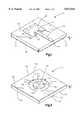
- FIG. 2is a perspective view similar to FIG. 1, illustrating a second embodiment of the present invention.
- FIG. 3is a perspective view similar to FIG. 1, illustrating a third embodiment of the present invention.
- FIG. 1illustrates a patch antenna 10 constructed in accordance with a first embodiment of the present invention.
- the antenna 10is capable of transmitting or receiving high frequency signals, such as a microwave frequency above 3,000 MHz, to or from a free space.
- the antenna 10includes a dielectric substrate 20 having substantially planar and parallel upper and lower surfaces 22 and 24, respectively.
- the substrate 20is substantially transparent.
- the substrate 20can be made of glass, laminated glass, polyester, Plexiglas®, which is manufactured by Rohm and Haas, Co., of Philadelphia, Pa., or any other generally rigid transparent material.
- the substrate 20is made of glass.
- the antenna 10has a ground layer 30 adhered to at least a substantial portion of the lower surface 24 of the substrate 20.
- the ground layer 30preferably covers the entire lower surface 24 of the substrate 20.
- the ground layer 30has a first thickness T, suitably between about 1000 and 1200 Angstroms and preferably about 1100 Angstroms, and is made of an optically transparent and electrically conducting coating material. It will be appreciated that as the thickness increases beyond about 1200 Angstroms, the transparency reduces.
- the coating materialis substantially transparent to visible and infrared light, passing at least about 30% of such light.
- electrically conductingit is meant that the surface resistance of the coating material is less than about 10 ohms/square and preferably about 5 ohms/square or less. If the surface resistance is higher, as with many conventional materials, it has been determined that a microwave signal, suitably above 3000 MHz, may be significantly attenuated and antenna efficiency may be decreased.
- the electrically conducting and optically transparent coating materialis preferably ECI-969®, which is manufactured by Evaporated Coatings Inc., of Willow Grove, Pa.
- Other suitable electrically conducting and optically transparent coating materialsinclude AgHT coatings, which are manufactured by Courtaulds Performance Films, of Canoga Park, Calif., indium tin oxide, cadmium tin oxide, zinc oxide as well as any other electrically conducting and optically transparent coating material.
- the antenna 10further includes an antenna layer 40 adhered to a portion of the upper surface 22 of the substrate 20, with the antenna layer 40 being spaced from ground layer 30 a predetermined distance generally equal to the thickness of substrate 20.
- the antenna layer 40preferably has a thickness approximately equal to the first thickness T of the ground layer 30.
- the antenna layer 40is made of an electrically conducting and optically transparent coating material and is preferably made of the same electrically conducting and optically transparent coating material as the ground layer 30.
- the shape of the antenna layer 40can be square, elliptical, circular or other shapes, although preferably rectangular, as shown in FIG. 1. It is also preferable that the surface area of the antenna layer 40 is less than the surface area of the ground layer 30. In the embodiment shown in FIG. 1, the length L of the antenna layer 40 should be about 0.5 or less of one wavelength of the carrier signal in the substrate and the width W of the antenna layer may be less than, greater than or equal to the length L of the antenna layer, and suitably about 1.5 L. Thus, the shape and size of the antenna layer 40 is determined in part by the frequencies for which the antenna will be used as well as by the electrical properties of the material selected for use as the substrate 20.
- the antennaalso includes a feed element, which is illustrated as a narrow feed layer 50 adhered to the upper surface 22 of the substrate 20.
- the feed layer 50has first and second ends 52 and 54 that extend transversely from an edge of the antenna layer 40 to an edge of the upper surface of the substrate.
- the second end 54can extend into the interior of the antenna layer 40 as an inset of microstrip feed to optimize the impedance match.
- the inset of feed layer 50is further defined by a pair of substantially parallel channels 55 and 57 formed on opposed sides of feed layer 50 and extending a predetermined distance into antenna layer 40.
- the feed layer 50is made of an electrically conducting and optically transparent coating material and is preferably made of the same electrically conducting optically transparent coating material as the ground and antenna layers 30 and 40, respectively.
- the feed layer 50has a thickness approximately equal to the first thickness T of the ground layer 30.
- the ground layer 30, the antenna layer 40 and the feed layer 50are preferably all about the same thickness.
- the feed layer 50communicates electromagnetic energy to or from the antenna layer 40. It should be understood that the elongated feed layer 50 could be eliminated in which case the antenna layer 40 of the antenna 10 could be excited by another type of feed element including another type of direct coupling, such a conventional probe (not shown) or by an electromagnetic coupling (not shown).
- the antenna 10may be manufactured, such as via lithography, by depositing a layer of an appropriate electrically conducting and optically transparent coating material of substantially uniform thickness on a substantial portion, and preferably the entire lower surface 24 of the substrate 20.
- a layer of conventional photoresistmay be applied to the upper surface 22 of the substrate 20.
- the layer of photoresistshould cover all of the upper surface 22 of the substrate 20, except for the portion of the upper surface to be covered by the antenna layer 40 and the feed layer 50. It will be understood that other types of direct feed or electromagnetic feed elements may be used, such as those set forth herein.
- a layer of the electrically conducting and optically transparent coating material of substantially uniform thicknessis adhered to the area of the upper surface 22 of the substrate 20 that is not covered by the photoresist.
- the photoresistis then removed by any conventional technique, such as by submersing the substrate 20 in a conventional liquid photoresist remover.
- the antenna 10, in its operational condition,is optically transparent in that it enables passage of at least about 30% of the visible light impinging on the antenna 10.
- FIG. 2illustrates a slot antenna 110 constructed in accordance with a second preferred embodiment of the present invention.
- the antenna 110is capable of transmitting or receiving high frequency signals, such as a microwave frequency above about 3,000 MHz, to or from a free space.
- the antenna 110includes a dielectric substrate 120 having parallel upper and lower surfaces 122 and 124, respectively.
- the substrate 120is transparent and may be made of the same material as the substrate 20 of antenna 10.
- the antenna 110has a ground layer 130 adhered to the upper surface 122 of the substrate 120.
- the ground layer 130thus extends along a plane that is substantially parallel and spaced apart from the plane on which the lower surface 124 of the substrate 120 extends.
- the ground layer 130has a centrally disposed inner edge 132 defining a circular opening 134 in the ground layer.
- the ground layer 130covers essentially all of the upper surface 122 of the substrate 120, except an open circular portion 136 which is centrally positioned on the upper surface of the substrate.
- the ground layer 130has a first thickness T, which is about 1000 to about 1200 Angstroms, and preferably about 1100 Angstroms.
- the ground layer 130is made of an optically transparent and electrically conducting coating material, as described with respect to antenna 10.
- the antenna 110further includes a generally circular antenna layer 140 adhered to the circular portion 136 of the upper surface 122 of the substrate 120.
- the antenna layer 140is defined by an outer circumferential edge 142.
- the antenna layer 140is disposed radially inward a predetermined distance from the inner edge 132 of the ground layer 130 in the generally circular opening 134 of the ground layer 130.
- the antenna layer 140has a thickness approximately equal to the first thickness T and is thus substantially coplanar with the ground layer 130.
- the antenna layer 140is made of an electrically conducting and optically transparent coating material and is preferably made of the same material as the ground layer 130.
- annular space or slot 144is formed between the ground layer 130 and the antenna layer 140.
- the annular slot 144is defined by the upper surface 122 of substrate 120, the inner edge 132 of ground layer 130 and the outer edge 142 of antenna layer 140.
- the annular slot 144provides a free space between the ground layer 130 and the antenna layer 140.
- the shape of the antenna layer 140 and the slot 144could vary from that shown in FIG. 2.
- the antenna layer 140could be square, rectangular or elliptical with the slot 144 having a corresponding shape and size.
- the antenna layer 140could instead be in the form of a straight slot (not shown)or a folded slot (not shown), all of which antenna shapes are known in the art.
- FIG. 2also illustrates a generally narrow and elongated feed layer 150 having first and second ends 152 and 154, respectively, adhered to the lower surface 124 of the substrate 120.
- First end 152is positioned adjacent to an edge of the lower surface 124 of the substrate 120, with the second end 154 extending transversely from such substrate edge to a position approximately beneath the central axis 141.
- the feed layer 150is made of an electrically conducting optically transparent coating material and is preferably made of the same material as the ground and antenna layers 130 and 140, respectively.
- the feed layer 150has a thickness approximately equal to the first thickness T, such that the ground layer 130, the antenna layer 140 and the feed layer 150 are all about the same thickness.
- the feed layer 150communicates electromagnetic energy, via an electromagnetic coupling consistent with Maxwell's equations, including Faraday's Law of Induction, to or from the antenna layer 140. It should be understood that the feed layer 150 could instead be directly coupled to the antenna layer 140 in a manner similar to that shown and described with respect to FIG. 1.
- the antenna 110is manufactured in a similar manner as described above in the first embodiment. More particularly, a layer of an appropriate electrically conducting and optically transparent coating material of substantially uniform thickness is deposited on predetermined portions of the upper surface 122 of substrate 120, with a generally annular slot 144. A layer of conventional photoresist may be applied to the upper surface 122 of the substrate 120, except for the portions to be covered by the antenna layer 140 and the ground layer 130. Similarly, photoresist may be applied to the lower surface 124, except for the area to where narrow feed layer 150 is to be applied.
- a layer of the electrically conducting and optically transparent coating material of substantially uniform thicknessis adhered to a predetermined portion of the lower surface 124 of the substrate 20 that is not covered by photoresist, preferably extending from an edge of substrate 120 to a position substantially beneath antenna layer 140.
- the photoresistis removed by any conventional technique, such as by submersing the substrate 20 in a conventional liquid photoresist remover. It will be apparent that such method of manufacture enables a relatively cost effective and simple application of the coating material layers.
- FIG. 3illustrates a slot antenna 210 constructed in accordance with a third embodiment of the present invention.
- Antenna 210is capable of transmitting or receiving high frequency signals, suitably in the microwave range or about 3000 Mhz or higher.
- Antenna 210includes a dielectric substrate 220 formed of a material substantially the same as that described with respect to FIGS. 1 and 2.
- Substrate 220includes an upper surface 222, a lower surface 224 substantially parallel to upper surface 222, and at least a pair of opposed side edges 225 and 227.
- the dielectric substrate 220is interposed between a layer of an optically transparent and electrically conducting coating material, which defines a ground layer 230 and an antenna layer 240, and a feed element 250.
- Ground layer 230is substantially coplanar with the antenna layer 240, with both having approximately the same thickness T, suitably about 1000 to about 1200 Angstroms.
- ground layer 230is coupled to antenna layer 240, such as by a direct or integral connection by the optically transparent and electrically conducting coating material on substrate upper surface 222.
- another optically transparent and electrically conducting materialsuitably a metal, might be used to couple the antenna and ground layers 240 and 230, respectively.
- FIG. 3is characterized by a tapered slot, generally indicated as 231, disposed between a substantial portion of the antenna and ground layers 240 and 230, respectively. More particularly, the tapered slot 231 is formed between the ground layer 230 and the antenna layer 240 along the upper surface 222 of substrate 220, with the slot 231 having two opposed side edges 233 and 235 tapering from a first spaced apart distance d 1 at substrate first edge 225 to a second spaced apart distance d 2 at a position distal from said substrate first edge 225. Slot 231 further includes a base portion 237, with slot side edges 233 and 235 being substantially parallel and spaced apart distance d 2 in base portion 237.
- Base portion 237extends from the tapering side edges to a position proximal the substrate second edge 227, with ground layer 230 being coupled to antenna layer 240 between base portion 237 and substrate second edge 227.
- slot 237defines a generally Y-shaped slot intermediate ground layer 230 and antenna layer 240. Similar to the embodiment of FIG. 2, slot 231 provides free space between ground layer 230 and antenna layer 240.
- feed element 250is an elongated feed element having first and second ends 252 and 254, respectively, and is a layer or strip, attached to the lower substrate surface 224 extending transverse to the slot base portion 237.
- Feed layer 250is formed of an optically transparent and electrically conducting material and is preferably the same coating material as the antenna and ground layers 240 and 230, respectively.
- Feed layer 250also preferably has approximately the same thickness T as antenna layer 240 and ground layer 230. It will be appreciated that alternative configurations of feed layers, such as those described with the other embodiments, also may be used with equal facility.
- the particular dimensions of slot 231may vary depending on the particular application.
- the antenna of FIG. 3may be manufactured in substantially the same manner as the other embodiments, suitably by lithography.
- the photoresist materialshould be applied to the upper and lower surfaces 222 and 224, respectively, of substrate 220, except for those areas to where the ground layer 230, antenna layer 240 and feed element 250 are to be formed. Accordingly, photoresist material will be deposited on upper surface 222 in accordance with the desired shape and dimensions of slot 231. Similarly, photoresist material should be applied to the entire lower surface 224, except where feed element 250 is to be deposited.
- the apparatus and method of the present inventionmay be utilized to form an antenna having a plurality of antenna layers, suitably in the form of a linear or planar array. Where such a plurality of antenna layers are formed, a common feed element may be used to excite several antenna layers.
Landscapes
- Waveguide Aerials (AREA)
Abstract
Description
ka=1,
Claims (20)
Priority Applications (1)
| Application Number | Priority Date | Filing Date | Title |
|---|---|---|---|
| US09/023,096US5872542A (en) | 1998-02-13 | 1998-02-13 | Optically transparent microstrip patch and slot antennas |
Applications Claiming Priority (1)
| Application Number | Priority Date | Filing Date | Title |
|---|---|---|---|
| US09/023,096US5872542A (en) | 1998-02-13 | 1998-02-13 | Optically transparent microstrip patch and slot antennas |
Publications (1)
| Publication Number | Publication Date |
|---|---|
| US5872542Atrue US5872542A (en) | 1999-02-16 |
Family
ID=21813115
Family Applications (1)
| Application Number | Title | Priority Date | Filing Date |
|---|---|---|---|
| US09/023,096Expired - Fee RelatedUS5872542A (en) | 1998-02-13 | 1998-02-13 | Optically transparent microstrip patch and slot antennas |
Country Status (1)
| Country | Link |
|---|---|
| US (1) | US5872542A (en) |
Cited By (120)
| Publication number | Priority date | Publication date | Assignee | Title |
|---|---|---|---|---|
| US6175332B1 (en)* | 1997-09-16 | 2001-01-16 | The United States Of America As Represented By The Secretary Of The Air Force | Diffractive beam forming and scanning antenna array |
| WO2001008261A1 (en)* | 1999-07-23 | 2001-02-01 | Robert Bosch Gmbh | Planar antenna |
| US6198437B1 (en) | 1998-07-09 | 2001-03-06 | The United States Of America As Represented By The Secretary Of The Air Force | Broadband patch/slot antenna |
| US6300908B1 (en)* | 1998-09-09 | 2001-10-09 | Centre National De La Recherche Scientifique (Cnrs) | Antenna |
| WO2001099231A1 (en)* | 2000-06-20 | 2001-12-27 | Harris Corporation | Optically transparent phase array antenna |
| US6337662B1 (en)* | 1997-04-30 | 2002-01-08 | Moteco Ab | Antenna for radio communications apparatus |
| US6417806B1 (en)* | 2001-01-31 | 2002-07-09 | Tantivy Communications, Inc. | Monopole antenna for array applications |
| US6496151B1 (en) | 2001-08-20 | 2002-12-17 | Northrop Grumman Corporation | End-fire cavity slot antenna array structure and method of forming |
| US6515626B2 (en)* | 1999-12-22 | 2003-02-04 | Hyundai Electronics Industries | Planar microstrip patch antenna for enhanced antenna efficiency and gain |
| US6563463B1 (en)* | 1999-05-24 | 2003-05-13 | Hitachi, Ltd. | Wireless tag, its manufacturing and its layout |
| US6606061B2 (en)* | 2001-10-03 | 2003-08-12 | Accton Technology Corporation | Broadband circularly polarized patch antenna |
| US6677906B2 (en)* | 2002-04-17 | 2004-01-13 | Dell Products L.P. | Glass antenna for laptop computers |
| US6778141B1 (en)* | 2003-03-06 | 2004-08-17 | D-Link Corporation | Patch antenna with increased bandwidth |
| US20050110690A1 (en)* | 2003-11-25 | 2005-05-26 | Lg Electronics Inc. | Wireless internal antenna for home network and digital electric home appliance |
| US20050253765A1 (en)* | 2004-04-06 | 2005-11-17 | Ali Louzir | Slot type planar antennas |
| US20060097923A1 (en)* | 2004-11-10 | 2006-05-11 | Qian Li | Non-uniform dielectric beam steering antenna |
| US20060181475A1 (en)* | 2005-02-16 | 2006-08-17 | Samsung Electronics Co., Ltd. | UWB antenna with unidirectional radiation pattern |
| US20060202898A1 (en)* | 2005-03-11 | 2006-09-14 | Agc Automotive Americas R&D, Inc. | Dual-layer planar antenna |
| US20070139275A1 (en)* | 2005-12-16 | 2007-06-21 | Deaett Michael A | Non-woven textile microwave antennas and components |
| CN100347906C (en)* | 2003-01-22 | 2007-11-07 | 友讯科技股份有限公司 | Microstrip antenna capable of increasing bandwidth |
| CN100356628C (en)* | 2005-07-01 | 2007-12-19 | 清华大学 | Plane antenna of wide-band wire less communication mobile terminal |
| US20090095908A1 (en)* | 2007-10-16 | 2009-04-16 | Imaging Source, Llc | Apparatus and methods for converting ambient heat to electricity |
| US20090115681A1 (en)* | 2007-11-01 | 2009-05-07 | Asustek Computer Inc. | Antenna device |
| FR2926929A1 (en)* | 2008-01-30 | 2009-07-31 | Bouygues Telecom Sa | PRINTED ANTENNA HAVING A BI-BEAM DIAGRAM |
| US20110006950A1 (en)* | 2008-02-28 | 2011-01-13 | Electronics And Telecommunications Research Instit | Microstrip antenna comprised of two slots |
| US20110139761A1 (en)* | 2009-12-15 | 2011-06-16 | Kabushiki Kaisha Kobe Seiko Sho (Kobe Steel, Ltd.) | Flux-cored wire for stainless steel arc welding |
| WO2011101488A1 (en) | 2010-02-22 | 2011-08-25 | Sas Taztag | Communication terminal having a monitor provided with a transparent antenna, and corresponding method |
| WO2012079029A1 (en)* | 2010-12-09 | 2012-06-14 | Agc Automotive Americas R&D, Inc. | Antenna assembly with progressively diverging antenna elements including an electrically conductive transparent layer |
| CN101420066B (en)* | 2008-11-21 | 2013-04-17 | 中国电子科技集团公司第三十八研究所 | Wideband single layer microstrip patch antenna |
| US20130260680A1 (en)* | 2012-04-02 | 2013-10-03 | Nuvoton Technology Corporation | Electronic device for reducing power consumption |
| US20140340279A1 (en)* | 2013-05-14 | 2014-11-20 | Paneratech, Inc. | Adaptive antenna feeding and method for optimizing the design thereof |
| US20150042420A1 (en)* | 2013-08-06 | 2015-02-12 | The United States Government As Represented By The | Optically transparent, radio frequency, planar transmission lines |
| JP2015043542A (en)* | 2013-08-26 | 2015-03-05 | 日本ピラー工業株式会社 | Slot antenna |
| US20160197653A1 (en)* | 2009-12-11 | 2016-07-07 | Micron Technology, Inc. | Wireless communication link using near field coupling |
| US9391360B1 (en) | 2013-04-16 | 2016-07-12 | Paneratech, Inc. | Antenna and method for optimizing the design thereof |
| US9502751B2 (en) | 2013-09-03 | 2016-11-22 | Paneratech, Inc. | Desensitized antenna and design method thereof |
| US9660851B2 (en) | 2010-05-28 | 2017-05-23 | Cohere Technologies, Inc. | Modulation and equalization in an orthonormal time-frequency shifting communications system |
| US9712354B2 (en) | 2010-05-28 | 2017-07-18 | Cohere Technologies, Inc. | Modulation and equalization in an orthonormal time-frequency shifting communications system |
| US9729281B2 (en) | 2011-05-26 | 2017-08-08 | Cohere Technologies, Inc. | Modulation and equalization in an orthonormal time-frequency shifting communications system |
| US9866363B2 (en) | 2015-06-18 | 2018-01-09 | Cohere Technologies, Inc. | System and method for coordinated management of network access points |
| US9893922B2 (en) | 2012-06-25 | 2018-02-13 | Cohere Technologies, Inc. | System and method for implementing orthogonal time frequency space communications using OFDM |
| US9900048B2 (en) | 2010-05-28 | 2018-02-20 | Cohere Technologies, Inc. | Modulation and equalization in an orthonormal time-frequency shifting communications system |
| US9917355B1 (en) | 2016-10-06 | 2018-03-13 | Toyota Motor Engineering & Manufacturing North America, Inc. | Wide field of view volumetric scan automotive radar with end-fire antenna |
| US9929783B2 (en) | 2012-06-25 | 2018-03-27 | Cohere Technologies, Inc. | Orthogonal time frequency space modulation system |
| US9967758B2 (en) | 2012-06-25 | 2018-05-08 | Cohere Technologies, Inc. | Multiple access in an orthogonal time frequency space communication system |
| US10003487B2 (en) | 2013-03-15 | 2018-06-19 | Cohere Technologies, Inc. | Symplectic orthogonal time frequency space modulation system |
| US10020854B2 (en) | 2012-06-25 | 2018-07-10 | Cohere Technologies, Inc. | Signal separation in an orthogonal time frequency space communication system using MIMO antenna arrays |
| US10020590B2 (en) | 2016-07-19 | 2018-07-10 | Toyota Motor Engineering & Manufacturing North America, Inc. | Grid bracket structure for mm-wave end-fire antenna array |
| US10063295B2 (en) | 2016-04-01 | 2018-08-28 | Cohere Technologies, Inc. | Tomlinson-Harashima precoding in an OTFS communication system |
| US10063354B2 (en) | 2010-05-28 | 2018-08-28 | Cohere Technologies, Inc. | Modulation and equalization in an orthonormal time-frequency shifting communications system |
| US10090973B2 (en) | 2015-05-11 | 2018-10-02 | Cohere Technologies, Inc. | Multiple access in an orthogonal time frequency space communication system |
| US10141636B2 (en) | 2016-09-28 | 2018-11-27 | Toyota Motor Engineering & Manufacturing North America, Inc. | Volumetric scan automotive radar with end-fire antenna on partially laminated multi-layer PCB |
| CN108963448A (en)* | 2018-06-26 | 2018-12-07 | 东南大学 | A kind of light is transparent and frequency reconfigurable antenna and its processing method |
| US10158394B2 (en) | 2015-05-11 | 2018-12-18 | Cohere Technologies, Inc. | Systems and methods for symplectic orthogonal time frequency shifting modulation and transmission of data |
| WO2019031270A1 (en)* | 2017-08-07 | 2019-02-14 | 株式会社ヨコオ | Antenna device |
| US10305163B2 (en)* | 2017-08-14 | 2019-05-28 | GM Global Technology Operations LLC | Method and apparatus for semitransparent antenna and transmission lines |
| US10334457B2 (en) | 2010-05-28 | 2019-06-25 | Cohere Technologies, Inc. | OTFS methods of data channel characterization and uses thereof |
| US10333209B2 (en) | 2016-07-19 | 2019-06-25 | Toyota Motor Engineering & Manufacturing North America, Inc. | Compact volume scan end-fire radar for vehicle applications |
| US10356632B2 (en) | 2017-01-27 | 2019-07-16 | Cohere Technologies, Inc. | Variable beamwidth multiband antenna |
| US10355887B2 (en) | 2016-04-01 | 2019-07-16 | Cohere Technologies, Inc. | Iterative two dimensional equalization of orthogonal time frequency space modulated signals |
| US10401491B2 (en) | 2016-11-15 | 2019-09-03 | Toyota Motor Engineering & Manufacturing North America, Inc. | Compact multi range automotive radar assembly with end-fire antennas on both sides of a printed circuit board |
| US10411843B2 (en) | 2012-06-25 | 2019-09-10 | Cohere Technologies, Inc. | Orthogonal time frequency space communication system compatible with OFDM |
| US10469215B2 (en) | 2012-06-25 | 2019-11-05 | Cohere Technologies, Inc. | Orthogonal time frequency space modulation system for the Internet of Things |
| US10524356B2 (en) | 2017-10-05 | 2019-12-31 | Eastman Kodak Company | Transparent antenna |
| US10555281B2 (en) | 2016-03-31 | 2020-02-04 | Cohere Technologies, Inc. | Wireless telecommunications system for high-mobility applications |
| US10568143B2 (en) | 2017-03-28 | 2020-02-18 | Cohere Technologies, Inc. | Windowed sequence for random access method and apparatus |
| US10574317B2 (en) | 2015-06-18 | 2020-02-25 | Cohere Technologies, Inc. | System and method for providing wireless communication services using configurable broadband infrastructure shared among multiple network operators |
| US10585187B2 (en) | 2017-02-24 | 2020-03-10 | Toyota Motor Engineering & Manufacturing North America, Inc. | Automotive radar with end-fire antenna fed by an optically generated signal transmitted through a fiber splitter to enhance a field of view |
| EP3609022A4 (en)* | 2017-04-04 | 2020-04-01 | Denso Corporation | TRANSLUCENT ANTENNA, COMMUNICATION MODULE ATTACHED TO A WINDOW AND PERIPHERAL MONITORING UNIT |
| US10666314B2 (en) | 2016-02-25 | 2020-05-26 | Cohere Technologies, Inc. | Reference signal packing for wireless communications |
| US10667148B1 (en) | 2010-05-28 | 2020-05-26 | Cohere Technologies, Inc. | Methods of operating and implementing wireless communications systems |
| US10666479B2 (en) | 2015-12-09 | 2020-05-26 | Cohere Technologies, Inc. | Pilot packing using complex orthogonal functions |
| US10681568B1 (en) | 2010-05-28 | 2020-06-09 | Cohere Technologies, Inc. | Methods of data channel characterization and uses thereof |
| US20200185822A1 (en)* | 2017-08-21 | 2020-06-11 | Denso Corporation | Antenna device |
| US10693692B2 (en) | 2016-03-23 | 2020-06-23 | Cohere Technologies, Inc. | Receiver-side processing of orthogonal time frequency space modulated signals |
| US10693581B2 (en) | 2015-07-12 | 2020-06-23 | Cohere Technologies, Inc. | Orthogonal time frequency space modulation over a plurality of narrow band subcarriers |
| US10749651B2 (en) | 2016-03-31 | 2020-08-18 | Cohere Technologies, Inc. | Channel acquistion using orthogonal time frequency space modulated pilot signal |
| US10826728B2 (en) | 2016-08-12 | 2020-11-03 | Cohere Technologies, Inc. | Localized equalization for channels with intercarrier interference |
| WO2020231763A1 (en)* | 2019-05-10 | 2020-11-19 | Corning Incorporated | Transparent package for window mounted transceiver unit |
| US10847887B2 (en) | 2017-10-05 | 2020-11-24 | Eastman Kodak Company | Method for fabricating a transparent antenna |
| US10855425B2 (en) | 2017-01-09 | 2020-12-01 | Cohere Technologies, Inc. | Pilot scrambling for channel estimation |
| US10873418B2 (en) | 2016-08-12 | 2020-12-22 | Cohere Technologies, Inc. | Iterative multi-level equalization and decoding |
| JP2020205515A (en)* | 2019-06-17 | 2020-12-24 | ソフトバンク株式会社 | Antenna, wireless communication device, and mobile body |
| US10892547B2 (en) | 2015-07-07 | 2021-01-12 | Cohere Technologies, Inc. | Inconspicuous multi-directional antenna system configured for multiple polarization modes |
| US10917204B2 (en) | 2016-08-12 | 2021-02-09 | Cohere Technologies, Inc. | Multi-user multiplexing of orthogonal time frequency space signals |
| US10938602B2 (en) | 2016-05-20 | 2021-03-02 | Cohere Technologies, Inc. | Iterative channel estimation and equalization with superimposed reference signals |
| US10938613B2 (en) | 2015-06-27 | 2021-03-02 | Cohere Technologies, Inc. | Orthogonal time frequency space communication system compatible with OFDM |
| US10951454B2 (en) | 2017-11-01 | 2021-03-16 | Cohere Technologies, Inc. | Precoding in wireless systems using orthogonal time frequency space multiplexing |
| US10965348B2 (en) | 2016-09-30 | 2021-03-30 | Cohere Technologies, Inc. | Uplink user resource allocation for orthogonal time frequency space modulation |
| US11025377B2 (en) | 2016-12-05 | 2021-06-01 | Cohere Technologies, Inc. | Fixed wireless access using orthogonal time frequency space modulation |
| WO2021110714A1 (en) | 2019-12-05 | 2021-06-10 | Saint-Gobain Glass France | Vehicle pane |
| WO2021110713A1 (en) | 2019-12-05 | 2021-06-10 | Saint-Gobain Glass France | Vehicle pane |
| US11038733B2 (en) | 2015-11-18 | 2021-06-15 | Cohere Technologies, Inc. | Orthogonal time frequency space modulation techniques |
| US11063804B2 (en) | 2017-04-24 | 2021-07-13 | Cohere Technologies, Inc. | Digital communication using lattice division multiplexing |
| US11070329B2 (en) | 2015-09-07 | 2021-07-20 | Cohere Technologies, Inc. | Multiple access using orthogonal time frequency space modulation |
| US11081787B2 (en)* | 2017-06-20 | 2021-08-03 | Viasat, Inc. | Antenna array radiation shielding |
| US11102034B2 (en) | 2017-09-06 | 2021-08-24 | Cohere Technologies, Inc. | Lattice reduction in orthogonal time frequency space modulation |
| US11114768B2 (en) | 2017-04-24 | 2021-09-07 | Cohere Technologies, Inc. | Multibeam antenna designs and operation |
| US11147087B2 (en) | 2017-04-21 | 2021-10-12 | Cohere Technologies, Inc. | Communication techniques using quasi-static properties of wireless channels |
| US11152957B2 (en) | 2017-09-29 | 2021-10-19 | Cohere Technologies, Inc. | Forward error correction using non-binary low density parity check codes |
| US11184122B2 (en) | 2017-12-04 | 2021-11-23 | Cohere Technologies, Inc. | Implementation of orthogonal time frequency space modulation for wireless communications |
| US11190308B2 (en) | 2017-09-15 | 2021-11-30 | Cohere Technologies, Inc. | Achieving synchronization in an orthogonal time frequency space signal receiver |
| US11190379B2 (en) | 2017-07-12 | 2021-11-30 | Cohere Technologies, Inc. | Data modulation schemes based on the Zak transform |
| US11271298B2 (en)* | 2017-10-23 | 2022-03-08 | Murata Manufacturing Co., Ltd. | Multi-antenna module and mobile terminal |
| US11283561B2 (en) | 2017-09-11 | 2022-03-22 | Cohere Technologies, Inc. | Wireless local area networks using orthogonal time frequency space modulation |
| US11310000B2 (en) | 2016-09-29 | 2022-04-19 | Cohere Technologies, Inc. | Transport block segmentation for multi-level codes |
| US11324008B2 (en) | 2017-08-14 | 2022-05-03 | Cohere Technologies, Inc. | Transmission resource allocation by splitting physical resource blocks |
| US11329848B2 (en) | 2018-06-13 | 2022-05-10 | Cohere Technologies, Inc. | Reciprocal calibration for channel estimation based on second-order statistics |
| US11355862B1 (en)* | 2019-12-06 | 2022-06-07 | Lockheed Martin Corporation | Ruggedized antennas and systems and methods thereof |
| US11489559B2 (en) | 2018-03-08 | 2022-11-01 | Cohere Technologies, Inc. | Scheduling multi-user MIMO transmissions in fixed wireless access systems |
| US11532891B2 (en) | 2017-09-20 | 2022-12-20 | Cohere Technologies, Inc. | Low cost electromagnetic feed network |
| US11546068B2 (en) | 2017-08-11 | 2023-01-03 | Cohere Technologies, Inc. | Ray tracing technique for wireless channel measurements |
| US11632270B2 (en) | 2018-02-08 | 2023-04-18 | Cohere Technologies, Inc. | Aspects of channel estimation for orthogonal time frequency space modulation for wireless communications |
| US11817987B2 (en) | 2017-04-11 | 2023-11-14 | Cohere Technologies, Inc. | Digital communication using dispersed orthogonal time frequency space modulated signals |
| US11831391B2 (en) | 2018-08-01 | 2023-11-28 | Cohere Technologies, Inc. | Airborne RF-head system |
| US11943089B2 (en) | 2010-05-28 | 2024-03-26 | Cohere Technologies, Inc. | Modulation and equalization in an orthonormal time-shifting communications system |
| US11967754B2 (en) | 2019-10-31 | 2024-04-23 | Samsung Display Co., Ltd. | Radio frequency device and electronic apparatus having the same |
| WO2025053818A1 (en)* | 2023-09-04 | 2025-03-13 | Turkiye Sise Ve Cam Fabrikalari Anonim Sirketi | A layered structure for a transparent microstrip patch antenna |
| US12311637B2 (en) | 2022-11-04 | 2025-05-27 | Agc Automotive Americas Co. | Laminated glazing assembly including an antenna assembly |
| US12335081B2 (en) | 2021-04-29 | 2025-06-17 | Cohere Technologies, Inc. | Ultra wide band signals using orthogonal time frequency space modulation |
Citations (12)
| Publication number | Priority date | Publication date | Assignee | Title |
|---|---|---|---|---|
| USRE29911E (en)* | 1973-04-17 | 1979-02-13 | Ball Corporation | Microstrip antenna structures and arrays |
| US4170013A (en)* | 1978-07-28 | 1979-10-02 | The United States Of America As Represented By The Secretary Of The Navy | Stripline patch antenna |
| US4197544A (en)* | 1977-09-28 | 1980-04-08 | The United States Of America As Represented By The Secretary Of The Navy | Windowed dual ground plane microstrip antennas |
| US4746925A (en)* | 1985-07-31 | 1988-05-24 | Toyota Jidosha Kabushiki Kaisha | Shielded dipole glass antenna with coaxial feed |
| US4768037A (en)* | 1986-12-19 | 1988-08-30 | Central Glass Company, Limited | Vehicle window glass antenna using transparent conductive film |
| US4849766A (en)* | 1986-07-04 | 1989-07-18 | Central Glass Company, Limited | Vehicle window glass antenna using transparent conductive film |
| US4864314A (en)* | 1985-01-17 | 1989-09-05 | Cossor Electronics Limited | Dual band antennas with microstrip array mounted atop a slot array |
| US4864316A (en)* | 1987-06-27 | 1989-09-05 | Nippon Sheet Glass Co. | Vehicle receiving apparatus using a window antenna |
| US5083135A (en)* | 1990-11-13 | 1992-01-21 | General Motors Corporation | Transparent film antenna for a vehicle window |
| US5528314A (en)* | 1995-05-22 | 1996-06-18 | General Motors Corporation | Transparent vehicle window antenna |
| US5598168A (en)* | 1994-12-08 | 1997-01-28 | Lucent Technologies Inc. | High efficiency microstrip antennas |
| US5767808A (en)* | 1995-01-13 | 1998-06-16 | Minnesota Mining And Manufacturing Company | Microstrip patch antennas using very thin conductors |
- 1998
- 1998-02-13USUS09/023,096patent/US5872542A/ennot_activeExpired - Fee Related
Patent Citations (12)
| Publication number | Priority date | Publication date | Assignee | Title |
|---|---|---|---|---|
| USRE29911E (en)* | 1973-04-17 | 1979-02-13 | Ball Corporation | Microstrip antenna structures and arrays |
| US4197544A (en)* | 1977-09-28 | 1980-04-08 | The United States Of America As Represented By The Secretary Of The Navy | Windowed dual ground plane microstrip antennas |
| US4170013A (en)* | 1978-07-28 | 1979-10-02 | The United States Of America As Represented By The Secretary Of The Navy | Stripline patch antenna |
| US4864314A (en)* | 1985-01-17 | 1989-09-05 | Cossor Electronics Limited | Dual band antennas with microstrip array mounted atop a slot array |
| US4746925A (en)* | 1985-07-31 | 1988-05-24 | Toyota Jidosha Kabushiki Kaisha | Shielded dipole glass antenna with coaxial feed |
| US4849766A (en)* | 1986-07-04 | 1989-07-18 | Central Glass Company, Limited | Vehicle window glass antenna using transparent conductive film |
| US4768037A (en)* | 1986-12-19 | 1988-08-30 | Central Glass Company, Limited | Vehicle window glass antenna using transparent conductive film |
| US4864316A (en)* | 1987-06-27 | 1989-09-05 | Nippon Sheet Glass Co. | Vehicle receiving apparatus using a window antenna |
| US5083135A (en)* | 1990-11-13 | 1992-01-21 | General Motors Corporation | Transparent film antenna for a vehicle window |
| US5598168A (en)* | 1994-12-08 | 1997-01-28 | Lucent Technologies Inc. | High efficiency microstrip antennas |
| US5767808A (en)* | 1995-01-13 | 1998-06-16 | Minnesota Mining And Manufacturing Company | Microstrip patch antennas using very thin conductors |
| US5528314A (en)* | 1995-05-22 | 1996-06-18 | General Motors Corporation | Transparent vehicle window antenna |
Non-Patent Citations (2)
| Title |
|---|
| "Transparent Conductors-A status Review", by K.L. Chopra, S. Major and D.K. Pandya, vol. 102(1983), pp. 1-46. |
| Transparent Conductors A status Review , by K.L. Chopra, S. Major and D.K. Pandya, vol. 102(1983), pp. 1 46.* |
Cited By (195)
| Publication number | Priority date | Publication date | Assignee | Title |
|---|---|---|---|---|
| US6337662B1 (en)* | 1997-04-30 | 2002-01-08 | Moteco Ab | Antenna for radio communications apparatus |
| US6509879B2 (en) | 1997-04-30 | 2003-01-21 | Moteco Ab | Antenna for a radio communications apparatus |
| US6175332B1 (en)* | 1997-09-16 | 2001-01-16 | The United States Of America As Represented By The Secretary Of The Air Force | Diffractive beam forming and scanning antenna array |
| US6198437B1 (en) | 1998-07-09 | 2001-03-06 | The United States Of America As Represented By The Secretary Of The Air Force | Broadband patch/slot antenna |
| US6300908B1 (en)* | 1998-09-09 | 2001-10-09 | Centre National De La Recherche Scientifique (Cnrs) | Antenna |
| US6795025B2 (en) | 1999-05-24 | 2004-09-21 | Hitachi, Ltd. | Wireless tag, its manufacturing and its layout |
| US6563463B1 (en)* | 1999-05-24 | 2003-05-13 | Hitachi, Ltd. | Wireless tag, its manufacturing and its layout |
| WO2001008261A1 (en)* | 1999-07-23 | 2001-02-01 | Robert Bosch Gmbh | Planar antenna |
| US6515626B2 (en)* | 1999-12-22 | 2003-02-04 | Hyundai Electronics Industries | Planar microstrip patch antenna for enhanced antenna efficiency and gain |
| WO2001099231A1 (en)* | 2000-06-20 | 2001-12-27 | Harris Corporation | Optically transparent phase array antenna |
| US6388621B1 (en) | 2000-06-20 | 2002-05-14 | Harris Corporation | Optically transparent phase array antenna |
| US6417806B1 (en)* | 2001-01-31 | 2002-07-09 | Tantivy Communications, Inc. | Monopole antenna for array applications |
| US6496151B1 (en) | 2001-08-20 | 2002-12-17 | Northrop Grumman Corporation | End-fire cavity slot antenna array structure and method of forming |
| US6606061B2 (en)* | 2001-10-03 | 2003-08-12 | Accton Technology Corporation | Broadband circularly polarized patch antenna |
| US6677906B2 (en)* | 2002-04-17 | 2004-01-13 | Dell Products L.P. | Glass antenna for laptop computers |
| CN100347906C (en)* | 2003-01-22 | 2007-11-07 | 友讯科技股份有限公司 | Microstrip antenna capable of increasing bandwidth |
| US6778141B1 (en)* | 2003-03-06 | 2004-08-17 | D-Link Corporation | Patch antenna with increased bandwidth |
| US20050110690A1 (en)* | 2003-11-25 | 2005-05-26 | Lg Electronics Inc. | Wireless internal antenna for home network and digital electric home appliance |
| US7145516B2 (en) | 2003-11-25 | 2006-12-05 | Lg Electronics Inc. | Wireless internal antenna for home network and digital electric home appliance |
| US20050253765A1 (en)* | 2004-04-06 | 2005-11-17 | Ali Louzir | Slot type planar antennas |
| US7088301B2 (en)* | 2004-04-06 | 2006-08-08 | Thomson Licensing | Slot type planar antennas |
| US20060097923A1 (en)* | 2004-11-10 | 2006-05-11 | Qian Li | Non-uniform dielectric beam steering antenna |
| US7126539B2 (en) | 2004-11-10 | 2006-10-24 | Agc Automotive Americas R&D, Inc. | Non-uniform dielectric beam steering antenna |
| US20060181475A1 (en)* | 2005-02-16 | 2006-08-17 | Samsung Electronics Co., Ltd. | UWB antenna with unidirectional radiation pattern |
| US7554507B2 (en)* | 2005-02-16 | 2009-06-30 | Samsung Electronics Co., Ltd. | UWB antenna with unidirectional radiation pattern |
| US7119751B2 (en) | 2005-03-11 | 2006-10-10 | Agc Automotive Americas R&D, Inc. | Dual-layer planar antenna |
| US20060202898A1 (en)* | 2005-03-11 | 2006-09-14 | Agc Automotive Americas R&D, Inc. | Dual-layer planar antenna |
| CN100356628C (en)* | 2005-07-01 | 2007-12-19 | 清华大学 | Plane antenna of wide-band wire less communication mobile terminal |
| US20070139275A1 (en)* | 2005-12-16 | 2007-06-21 | Deaett Michael A | Non-woven textile microwave antennas and components |
| US7463198B2 (en) | 2005-12-16 | 2008-12-09 | Applied Radar Inc. | Non-woven textile microwave antennas and components |
| US20090095908A1 (en)* | 2007-10-16 | 2009-04-16 | Imaging Source, Llc | Apparatus and methods for converting ambient heat to electricity |
| US20090115681A1 (en)* | 2007-11-01 | 2009-05-07 | Asustek Computer Inc. | Antenna device |
| US7924237B2 (en)* | 2007-11-01 | 2011-04-12 | Asustek Computer Inc. | Antenna device |
| US20090224980A1 (en)* | 2008-01-30 | 2009-09-10 | Eduardo Motta Cruz | Printed antenna having a dual-beam diagram |
| EP2086053A1 (en)* | 2008-01-30 | 2009-08-05 | Bouygues Telecom | Printed antenna with a two-beam diagram |
| FR2926929A1 (en)* | 2008-01-30 | 2009-07-31 | Bouygues Telecom Sa | PRINTED ANTENNA HAVING A BI-BEAM DIAGRAM |
| US8502734B2 (en)* | 2008-01-30 | 2013-08-06 | Bouygues Telecom | Printed antenna having a dual-beam diagram |
| US20110006950A1 (en)* | 2008-02-28 | 2011-01-13 | Electronics And Telecommunications Research Instit | Microstrip antenna comprised of two slots |
| CN101420066B (en)* | 2008-11-21 | 2013-04-17 | 中国电子科技集团公司第三十八研究所 | Wideband single layer microstrip patch antenna |
| US20160197653A1 (en)* | 2009-12-11 | 2016-07-07 | Micron Technology, Inc. | Wireless communication link using near field coupling |
| US10476556B2 (en)* | 2009-12-11 | 2019-11-12 | Micron Technology, Inc. | Wireless communication link using near field coupling |
| US20190052316A1 (en)* | 2009-12-11 | 2019-02-14 | Micron Technology, Inc. | Wireless communication link using near field coupling |
| US10128916B2 (en)* | 2009-12-11 | 2018-11-13 | Micron Technology, Inc. | Wireless communication link using near field coupling |
| US20110139761A1 (en)* | 2009-12-15 | 2011-06-16 | Kabushiki Kaisha Kobe Seiko Sho (Kobe Steel, Ltd.) | Flux-cored wire for stainless steel arc welding |
| WO2011101488A1 (en) | 2010-02-22 | 2011-08-25 | Sas Taztag | Communication terminal having a monitor provided with a transparent antenna, and corresponding method |
| US10334457B2 (en) | 2010-05-28 | 2019-06-25 | Cohere Technologies, Inc. | OTFS methods of data channel characterization and uses thereof |
| US11038636B2 (en) | 2010-05-28 | 2021-06-15 | Cohere Technologies, Inc. | Modulation and equalization in an orthonormal time-frequency shifting communications system |
| US10681568B1 (en) | 2010-05-28 | 2020-06-09 | Cohere Technologies, Inc. | Methods of data channel characterization and uses thereof |
| US11943089B2 (en) | 2010-05-28 | 2024-03-26 | Cohere Technologies, Inc. | Modulation and equalization in an orthonormal time-shifting communications system |
| US10063354B2 (en) | 2010-05-28 | 2018-08-28 | Cohere Technologies, Inc. | Modulation and equalization in an orthonormal time-frequency shifting communications system |
| US10667148B1 (en) | 2010-05-28 | 2020-05-26 | Cohere Technologies, Inc. | Methods of operating and implementing wireless communications systems |
| US10637697B2 (en) | 2010-05-28 | 2020-04-28 | Cohere Technologies, Inc. | Modulation and equalization in an orthonormal time-frequency shifting communications system |
| US9660851B2 (en) | 2010-05-28 | 2017-05-23 | Cohere Technologies, Inc. | Modulation and equalization in an orthonormal time-frequency shifting communications system |
| US9712354B2 (en) | 2010-05-28 | 2017-07-18 | Cohere Technologies, Inc. | Modulation and equalization in an orthonormal time-frequency shifting communications system |
| US12149386B2 (en) | 2010-05-28 | 2024-11-19 | Cohere Technologies, Inc. | Method and apparatus for determining a channel state of an impaired data channel |
| US10959114B2 (en) | 2010-05-28 | 2021-03-23 | Cohere Technologies, Inc. | OTFS methods of data channel characterization and uses thereof |
| US12009960B2 (en) | 2010-05-28 | 2024-06-11 | Cohere Technologies, Inc. | Location-assisted channel estimation methods in wireless communications systems |
| US9900048B2 (en) | 2010-05-28 | 2018-02-20 | Cohere Technologies, Inc. | Modulation and equalization in an orthonormal time-frequency shifting communications system |
| US10567125B2 (en) | 2010-05-28 | 2020-02-18 | Cohere Technologies, Inc. | Modulation and equalization in an orthonormal time-frequency shifting communications system |
| US12375336B2 (en) | 2010-05-28 | 2025-07-29 | Cohere Technologies, Inc. | Modulation and equalization in an orthonormal time-shifting communications system |
| US11470485B2 (en) | 2010-05-28 | 2022-10-11 | Cohere Technologies, Inc. | Methods of operating and implementing wireless communications systems |
| US11665041B2 (en) | 2010-05-28 | 2023-05-30 | Cohere Technologies, Inc. | Modulation and equalization in an orthonormal time-frequency shifting communications system |
| US11646913B2 (en) | 2010-05-28 | 2023-05-09 | Cohere Technologies, Inc. | Methods of data communication in multipath channels |
| US10341155B2 (en) | 2010-05-28 | 2019-07-02 | Cohere Technologies, Inc. | Modulation and equalization in an orthonormal time-frequency shifting communications system |
| WO2012079029A1 (en)* | 2010-12-09 | 2012-06-14 | Agc Automotive Americas R&D, Inc. | Antenna assembly with progressively diverging antenna elements including an electrically conductive transparent layer |
| US9729281B2 (en) | 2011-05-26 | 2017-08-08 | Cohere Technologies, Inc. | Modulation and equalization in an orthonormal time-frequency shifting communications system |
| US20130260680A1 (en)* | 2012-04-02 | 2013-10-03 | Nuvoton Technology Corporation | Electronic device for reducing power consumption |
| US8971963B2 (en)* | 2012-04-02 | 2015-03-03 | Nuvoton Technology Corporation | Electronic device for reducing power consumption |
| US9912507B2 (en) | 2012-06-25 | 2018-03-06 | Cohere Technologies, Inc. | Orthogonal time frequency space communication system compatible with OFDM |
| US10020854B2 (en) | 2012-06-25 | 2018-07-10 | Cohere Technologies, Inc. | Signal separation in an orthogonal time frequency space communication system using MIMO antenna arrays |
| US10411843B2 (en) | 2012-06-25 | 2019-09-10 | Cohere Technologies, Inc. | Orthogonal time frequency space communication system compatible with OFDM |
| US9967758B2 (en) | 2012-06-25 | 2018-05-08 | Cohere Technologies, Inc. | Multiple access in an orthogonal time frequency space communication system |
| US10476564B2 (en) | 2012-06-25 | 2019-11-12 | Cohere Technologies, Inc. | Variable latency data communication using orthogonal time frequency space modulation |
| US10469215B2 (en) | 2012-06-25 | 2019-11-05 | Cohere Technologies, Inc. | Orthogonal time frequency space modulation system for the Internet of Things |
| US10090972B2 (en) | 2012-06-25 | 2018-10-02 | Cohere Technologies, Inc. | System and method for two-dimensional equalization in an orthogonal time frequency space communication system |
| US9893922B2 (en) | 2012-06-25 | 2018-02-13 | Cohere Technologies, Inc. | System and method for implementing orthogonal time frequency space communications using OFDM |
| US9929783B2 (en) | 2012-06-25 | 2018-03-27 | Cohere Technologies, Inc. | Orthogonal time frequency space modulation system |
| US10003487B2 (en) | 2013-03-15 | 2018-06-19 | Cohere Technologies, Inc. | Symplectic orthogonal time frequency space modulation system |
| US9391360B1 (en) | 2013-04-16 | 2016-07-12 | Paneratech, Inc. | Antenna and method for optimizing the design thereof |
| US20140340279A1 (en)* | 2013-05-14 | 2014-11-20 | Paneratech, Inc. | Adaptive antenna feeding and method for optimizing the design thereof |
| US9413059B2 (en)* | 2013-05-14 | 2016-08-09 | Paneratech, Inc. | Adaptive antenna feeding and method for optimizing the design thereof |
| US20150042420A1 (en)* | 2013-08-06 | 2015-02-12 | The United States Government As Represented By The | Optically transparent, radio frequency, planar transmission lines |
| US9356331B2 (en)* | 2013-08-06 | 2016-05-31 | The United States Of America As Represented By The Secretary Of The Army | Optically transparent, radio frequency, planar transmission lines |
| JP2015043542A (en)* | 2013-08-26 | 2015-03-05 | 日本ピラー工業株式会社 | Slot antenna |
| US9502751B2 (en) | 2013-09-03 | 2016-11-22 | Paneratech, Inc. | Desensitized antenna and design method thereof |
| US10090973B2 (en) | 2015-05-11 | 2018-10-02 | Cohere Technologies, Inc. | Multiple access in an orthogonal time frequency space communication system |
| US10158394B2 (en) | 2015-05-11 | 2018-12-18 | Cohere Technologies, Inc. | Systems and methods for symplectic orthogonal time frequency shifting modulation and transmission of data |
| US10574317B2 (en) | 2015-06-18 | 2020-02-25 | Cohere Technologies, Inc. | System and method for providing wireless communication services using configurable broadband infrastructure shared among multiple network operators |
| US9866363B2 (en) | 2015-06-18 | 2018-01-09 | Cohere Technologies, Inc. | System and method for coordinated management of network access points |
| US11456908B2 (en) | 2015-06-27 | 2022-09-27 | Cohere Technologies, Inc. | Orthogonal time frequency space communication system compatible with OFDM |
| US10938613B2 (en) | 2015-06-27 | 2021-03-02 | Cohere Technologies, Inc. | Orthogonal time frequency space communication system compatible with OFDM |
| US10892547B2 (en) | 2015-07-07 | 2021-01-12 | Cohere Technologies, Inc. | Inconspicuous multi-directional antenna system configured for multiple polarization modes |
| US11601213B2 (en) | 2015-07-12 | 2023-03-07 | Cohere Technologies, Inc. | Orthogonal time frequency space modulation over a plurality of narrow band subcarriers |
| US10693581B2 (en) | 2015-07-12 | 2020-06-23 | Cohere Technologies, Inc. | Orthogonal time frequency space modulation over a plurality of narrow band subcarriers |
| US11070329B2 (en) | 2015-09-07 | 2021-07-20 | Cohere Technologies, Inc. | Multiple access using orthogonal time frequency space modulation |
| US12068846B2 (en) | 2015-09-07 | 2024-08-20 | Cohere Technologies, Inc. | Multiple access using orthogonal time frequency space modulation |
| US11894967B2 (en) | 2015-11-18 | 2024-02-06 | Zte Corporation | Orthogonal time frequency space modulation techniques |
| US11038733B2 (en) | 2015-11-18 | 2021-06-15 | Cohere Technologies, Inc. | Orthogonal time frequency space modulation techniques |
| US11575557B2 (en) | 2015-11-18 | 2023-02-07 | Cohere Technologies, Inc. | Orthogonal time frequency space modulation techniques |
| US12184468B2 (en) | 2015-11-18 | 2024-12-31 | Cohere Technologies, Inc. | Orthogonal time frequency space modulation techniques |
| US10666479B2 (en) | 2015-12-09 | 2020-05-26 | Cohere Technologies, Inc. | Pilot packing using complex orthogonal functions |
| US10666314B2 (en) | 2016-02-25 | 2020-05-26 | Cohere Technologies, Inc. | Reference signal packing for wireless communications |
| US11362872B2 (en) | 2016-03-23 | 2022-06-14 | Cohere Technologies, Inc. | Receiver-side processing of orthogonal time frequency space modulated signals |
| US10693692B2 (en) | 2016-03-23 | 2020-06-23 | Cohere Technologies, Inc. | Receiver-side processing of orthogonal time frequency space modulated signals |
| US10555281B2 (en) | 2016-03-31 | 2020-02-04 | Cohere Technologies, Inc. | Wireless telecommunications system for high-mobility applications |
| US10716095B2 (en) | 2016-03-31 | 2020-07-14 | Cohere Technologies, Inc. | Multiple access in wireless telecommunications system for high-mobility applications |
| US10749651B2 (en) | 2016-03-31 | 2020-08-18 | Cohere Technologies, Inc. | Channel acquistion using orthogonal time frequency space modulated pilot signal |
| US11362786B2 (en) | 2016-03-31 | 2022-06-14 | Cohere Technologies, Inc. | Channel acquisition using orthogonal time frequency space modulated pilot signals |
| US11425693B2 (en) | 2016-03-31 | 2022-08-23 | Cohere Technologies, Inc. | Multiple access in wireless telecommunications system for high-mobility applications |
| US11968144B2 (en) | 2016-03-31 | 2024-04-23 | Cohere Technologies, Inc. | Channel acquisition using orthogonal time frequency space modulated pilot signals |
| US10541734B2 (en) | 2016-04-01 | 2020-01-21 | Cohere Technologies, Inc. | Tomlinson-Harashima precoding in an OTFS communication system |
| US11018731B2 (en) | 2016-04-01 | 2021-05-25 | Cohere Technologies, Inc. | Tomlinson-harashima precoding in an OTFS communication system |
| US10673659B2 (en) | 2016-04-01 | 2020-06-02 | Cohere Technologies, Inc. | Iterative two dimensional equalization of orthogonal time frequency space modulated signals |
| US10355887B2 (en) | 2016-04-01 | 2019-07-16 | Cohere Technologies, Inc. | Iterative two dimensional equalization of orthogonal time frequency space modulated signals |
| US10063295B2 (en) | 2016-04-01 | 2018-08-28 | Cohere Technologies, Inc. | Tomlinson-Harashima precoding in an OTFS communication system |
| US11646844B2 (en) | 2016-04-01 | 2023-05-09 | Cohere Technologies, Inc. | Tomlinson-harashima precoding in an OTFS communication system |
| US10938602B2 (en) | 2016-05-20 | 2021-03-02 | Cohere Technologies, Inc. | Iterative channel estimation and equalization with superimposed reference signals |
| US11362866B2 (en) | 2016-05-20 | 2022-06-14 | Cohere Technologies, Inc. | Iterative channel estimation and equalization with superimposed reference signals |
| US10333209B2 (en) | 2016-07-19 | 2019-06-25 | Toyota Motor Engineering & Manufacturing North America, Inc. | Compact volume scan end-fire radar for vehicle applications |
| US10020590B2 (en) | 2016-07-19 | 2018-07-10 | Toyota Motor Engineering & Manufacturing North America, Inc. | Grid bracket structure for mm-wave end-fire antenna array |
| US11451348B2 (en) | 2016-08-12 | 2022-09-20 | Cohere Technologies, Inc. | Multi-user multiplexing of orthogonal time frequency space signals |
| US10826728B2 (en) | 2016-08-12 | 2020-11-03 | Cohere Technologies, Inc. | Localized equalization for channels with intercarrier interference |
| US10917204B2 (en) | 2016-08-12 | 2021-02-09 | Cohere Technologies, Inc. | Multi-user multiplexing of orthogonal time frequency space signals |
| US10873418B2 (en) | 2016-08-12 | 2020-12-22 | Cohere Technologies, Inc. | Iterative multi-level equalization and decoding |
| US10141636B2 (en) | 2016-09-28 | 2018-11-27 | Toyota Motor Engineering & Manufacturing North America, Inc. | Volumetric scan automotive radar with end-fire antenna on partially laminated multi-layer PCB |
| US11310000B2 (en) | 2016-09-29 | 2022-04-19 | Cohere Technologies, Inc. | Transport block segmentation for multi-level codes |
| US10965348B2 (en) | 2016-09-30 | 2021-03-30 | Cohere Technologies, Inc. | Uplink user resource allocation for orthogonal time frequency space modulation |
| US9917355B1 (en) | 2016-10-06 | 2018-03-13 | Toyota Motor Engineering & Manufacturing North America, Inc. | Wide field of view volumetric scan automotive radar with end-fire antenna |
| US10401491B2 (en) | 2016-11-15 | 2019-09-03 | Toyota Motor Engineering & Manufacturing North America, Inc. | Compact multi range automotive radar assembly with end-fire antennas on both sides of a printed circuit board |
| US11558157B2 (en) | 2016-12-05 | 2023-01-17 | Cohere Technologies, Inc. | Fixed wireless access using orthogonal time frequency space modulation |
| US11843552B2 (en) | 2016-12-05 | 2023-12-12 | Cohere Technologies, Inc. | Fixed wireless access using orthogonal time frequency space modulation |
| US11025377B2 (en) | 2016-12-05 | 2021-06-01 | Cohere Technologies, Inc. | Fixed wireless access using orthogonal time frequency space modulation |
| US10855425B2 (en) | 2017-01-09 | 2020-12-01 | Cohere Technologies, Inc. | Pilot scrambling for channel estimation |
| US10356632B2 (en) | 2017-01-27 | 2019-07-16 | Cohere Technologies, Inc. | Variable beamwidth multiband antenna |
| US10585187B2 (en) | 2017-02-24 | 2020-03-10 | Toyota Motor Engineering & Manufacturing North America, Inc. | Automotive radar with end-fire antenna fed by an optically generated signal transmitted through a fiber splitter to enhance a field of view |
| US10568143B2 (en) | 2017-03-28 | 2020-02-18 | Cohere Technologies, Inc. | Windowed sequence for random access method and apparatus |
| EP3609022A4 (en)* | 2017-04-04 | 2020-04-01 | Denso Corporation | TRANSLUCENT ANTENNA, COMMUNICATION MODULE ATTACHED TO A WINDOW AND PERIPHERAL MONITORING UNIT |
| US11139579B2 (en)* | 2017-04-04 | 2021-10-05 | Denso Corporation | Light-transmissive antenna, window affixing type communication module, and periphery monitoring unit |
| US11817987B2 (en) | 2017-04-11 | 2023-11-14 | Cohere Technologies, Inc. | Digital communication using dispersed orthogonal time frequency space modulated signals |
| US11991738B2 (en) | 2017-04-21 | 2024-05-21 | Cohere Technologies, Inc. | Communication techniques using quasi-static properties of wireless channels |
| US11147087B2 (en) | 2017-04-21 | 2021-10-12 | Cohere Technologies, Inc. | Communication techniques using quasi-static properties of wireless channels |
| US11737129B2 (en) | 2017-04-21 | 2023-08-22 | Cohere Technologies, Inc. | Communication techniques using quasi-static properties of wireless channels |
| US11063804B2 (en) | 2017-04-24 | 2021-07-13 | Cohere Technologies, Inc. | Digital communication using lattice division multiplexing |
| US11670863B2 (en) | 2017-04-24 | 2023-06-06 | Cohere Technologies, Inc. | Multibeam antenna designs and operation |
| US11114768B2 (en) | 2017-04-24 | 2021-09-07 | Cohere Technologies, Inc. | Multibeam antenna designs and operation |
| US11611146B2 (en) | 2017-06-20 | 2023-03-21 | Viasat Inc. | Antenna array radiation shielding |
| US11081787B2 (en)* | 2017-06-20 | 2021-08-03 | Viasat, Inc. | Antenna array radiation shielding |
| US11190379B2 (en) | 2017-07-12 | 2021-11-30 | Cohere Technologies, Inc. | Data modulation schemes based on the Zak transform |
| WO2019031270A1 (en)* | 2017-08-07 | 2019-02-14 | 株式会社ヨコオ | Antenna device |
| US11546068B2 (en) | 2017-08-11 | 2023-01-03 | Cohere Technologies, Inc. | Ray tracing technique for wireless channel measurements |
| US10305163B2 (en)* | 2017-08-14 | 2019-05-28 | GM Global Technology Operations LLC | Method and apparatus for semitransparent antenna and transmission lines |
| US11632791B2 (en) | 2017-08-14 | 2023-04-18 | Cohere Technologies, Inc. | Transmission resource allocation by splitting physical resource blocks |
| US11324008B2 (en) | 2017-08-14 | 2022-05-03 | Cohere Technologies, Inc. | Transmission resource allocation by splitting physical resource blocks |
| US11824259B2 (en)* | 2017-08-21 | 2023-11-21 | Denso Corporation | Antenna device |
| US20200185822A1 (en)* | 2017-08-21 | 2020-06-11 | Denso Corporation | Antenna device |
| US11533203B2 (en) | 2017-09-06 | 2022-12-20 | Cohere Technologies, Inc. | Lattice reduction in wireless communication |
| US11102034B2 (en) | 2017-09-06 | 2021-08-24 | Cohere Technologies, Inc. | Lattice reduction in orthogonal time frequency space modulation |
| US11283561B2 (en) | 2017-09-11 | 2022-03-22 | Cohere Technologies, Inc. | Wireless local area networks using orthogonal time frequency space modulation |
| US11637663B2 (en) | 2017-09-15 | 2023-04-25 | Cohere Techologies, Inc. | Achieving synchronization in an orthogonal time frequency space signal receiver |
| US11190308B2 (en) | 2017-09-15 | 2021-11-30 | Cohere Technologies, Inc. | Achieving synchronization in an orthogonal time frequency space signal receiver |
| US11532891B2 (en) | 2017-09-20 | 2022-12-20 | Cohere Technologies, Inc. | Low cost electromagnetic feed network |
| US11632133B2 (en) | 2017-09-29 | 2023-04-18 | Cohere Technologies, Inc. | Forward error correction using non-binary low density parity check codes |
| US11152957B2 (en) | 2017-09-29 | 2021-10-19 | Cohere Technologies, Inc. | Forward error correction using non-binary low density parity check codes |
| US10847887B2 (en) | 2017-10-05 | 2020-11-24 | Eastman Kodak Company | Method for fabricating a transparent antenna |
| US10524356B2 (en) | 2017-10-05 | 2019-12-31 | Eastman Kodak Company | Transparent antenna |
| US11271298B2 (en)* | 2017-10-23 | 2022-03-08 | Murata Manufacturing Co., Ltd. | Multi-antenna module and mobile terminal |
| US10951454B2 (en) | 2017-11-01 | 2021-03-16 | Cohere Technologies, Inc. | Precoding in wireless systems using orthogonal time frequency space multiplexing |
| US11296919B2 (en) | 2017-11-01 | 2022-04-05 | Cohere Technologies, Inc. | Precoding in wireless systems using orthogonal time frequency space multiplexing |
| US11184122B2 (en) | 2017-12-04 | 2021-11-23 | Cohere Technologies, Inc. | Implementation of orthogonal time frequency space modulation for wireless communications |
| US12177057B2 (en) | 2017-12-04 | 2024-12-24 | Cohere Technologies, Inc. | Implementation of orthogonal time frequency space modulation for wireless communications |
| US11848810B2 (en) | 2017-12-04 | 2023-12-19 | Cohere Technologies, Inc. | Implementation of orthogonal time frequency space modulation for wireless communications |
| US11632270B2 (en) | 2018-02-08 | 2023-04-18 | Cohere Technologies, Inc. | Aspects of channel estimation for orthogonal time frequency space modulation for wireless communications |
| US11489559B2 (en) | 2018-03-08 | 2022-11-01 | Cohere Technologies, Inc. | Scheduling multi-user MIMO transmissions in fixed wireless access systems |
| US12231266B2 (en) | 2018-06-13 | 2025-02-18 | Cohere Technologies, Inc. | Reciprocal calibration for channel estimation based on second-order statistics |
| US11329848B2 (en) | 2018-06-13 | 2022-05-10 | Cohere Technologies, Inc. | Reciprocal calibration for channel estimation based on second-order statistics |
| US11962435B2 (en) | 2018-06-13 | 2024-04-16 | Cohere Technologies, Inc. | Reciprocal calibration for channel estimation based on second-order statistics |
| CN108963448B (en)* | 2018-06-26 | 2020-08-11 | 东南大学 | A kind of processing method of optically transparent and frequency reconfigurable antenna |
| CN108963448A (en)* | 2018-06-26 | 2018-12-07 | 东南大学 | A kind of light is transparent and frequency reconfigurable antenna and its processing method |
| US11831391B2 (en) | 2018-08-01 | 2023-11-28 | Cohere Technologies, Inc. | Airborne RF-head system |
| US12301332B2 (en) | 2018-08-01 | 2025-05-13 | Cohere Technologies, Inc. | Airborne RF-head system |
| WO2020231763A1 (en)* | 2019-05-10 | 2020-11-19 | Corning Incorporated | Transparent package for window mounted transceiver unit |
| KR20210154821A (en)* | 2019-05-10 | 2021-12-21 | 코닝 인코포레이티드 | Transparent package for window-mounted transceiver unit |
| CN113841294A (en)* | 2019-05-10 | 2021-12-24 | 康宁股份有限公司 | Transparent encapsulation for window mounted transceiver unit |
| US11881613B2 (en) | 2019-05-10 | 2024-01-23 | Corning Incorporated | Transparent package for window mounted transceiver unit |
| JP2020205515A (en)* | 2019-06-17 | 2020-12-24 | ソフトバンク株式会社 | Antenna, wireless communication device, and mobile body |
| US11967754B2 (en) | 2019-10-31 | 2024-04-23 | Samsung Display Co., Ltd. | Radio frequency device and electronic apparatus having the same |
| DE202020005727U1 (en) | 2019-12-05 | 2022-03-08 | Saint-Gobain Glass France | vehicle window |
| CN113474944A (en)* | 2019-12-05 | 2021-10-01 | 法国圣戈班玻璃厂 | Vehicle glazing |
| WO2021110714A1 (en) | 2019-12-05 | 2021-06-10 | Saint-Gobain Glass France | Vehicle pane |
| WO2021110713A1 (en) | 2019-12-05 | 2021-06-10 | Saint-Gobain Glass France | Vehicle pane |
| US12068524B2 (en) | 2019-12-05 | 2024-08-20 | Saint-Gobain Glass France | Vehicle pane |
| US11355862B1 (en)* | 2019-12-06 | 2022-06-07 | Lockheed Martin Corporation | Ruggedized antennas and systems and methods thereof |
| US12335081B2 (en) | 2021-04-29 | 2025-06-17 | Cohere Technologies, Inc. | Ultra wide band signals using orthogonal time frequency space modulation |
| US12311637B2 (en) | 2022-11-04 | 2025-05-27 | Agc Automotive Americas Co. | Laminated glazing assembly including an antenna assembly |
| WO2025053818A1 (en)* | 2023-09-04 | 2025-03-13 | Turkiye Sise Ve Cam Fabrikalari Anonim Sirketi | A layered structure for a transparent microstrip patch antenna |
Similar Documents
| Publication | Publication Date | Title |
|---|---|---|
| US5872542A (en) | Optically transparent microstrip patch and slot antennas | |
| US5448252A (en) | Wide bandwidth microstrip patch antenna | |
| US5561435A (en) | Planar lower cost multilayer dual-band microstrip antenna | |
| US11837791B2 (en) | Microstrip patch antenna with increased bandwidth | |
| US6285325B1 (en) | Compact wideband microstrip antenna with leaky-wave excitation | |
| US10879618B2 (en) | Wideband substrate integrated waveguide slot antenna | |
| EP1266429B1 (en) | Vivaldi cloverleaf antenna | |
| US7006043B1 (en) | Wideband circularly polarized single layer compact microstrip antenna | |
| US5815122A (en) | Slot spiral antenna with integrated balun and feed | |
| US6281843B1 (en) | Planar broadband dipole antenna for linearly polarized waves | |
| US6906674B2 (en) | Aperture antenna having a high-impedance backing | |
| US6160522A (en) | Cavity-backed slot antenna | |
| EP0798807A2 (en) | TEM slot array antenna | |
| EP1130676A2 (en) | Patch antenna with embedded impedance transformer and methods for making same | |
| EP2453521A1 (en) | Windowpane for vehicle and antenna | |
| US5327148A (en) | Ferrite microstrip antenna | |
| FR2772518A1 (en) | SHORT-CIRCUIT ANTENNA MADE ACCORDING TO MICRO-TAPE TECHNIQUE AND DEVICE INCLUDING THIS ANTENNA | |
| DE10118742A1 (en) | Microwave or extremely high frequency module with integrated slot antenna | |
| Ammann | Design of rectangular microstrip patch antennas for the 2.4 GHz band | |
| US6191750B1 (en) | Traveling wave slot antenna and method of making same | |
| AU676114B2 (en) | End launched microstrip (or stripline)to waveguide transition using a cavity backed slot fed by a t-shaped microstrip line | |
| KR970004148A (en) | Planar and non-planar double sea-patch antennas with different aperture shapes | |
| JPH03192804A (en) | Antenna system | |
| US4507664A (en) | Dielectric image waveguide antenna array | |
| US4809008A (en) | Broadband microstrip antenna |
Legal Events
| Date | Code | Title | Description |
|---|---|---|---|
| AS | Assignment | Owner name:FEDERAL DATA CORPORATION, OHIO Free format text:ASSIGNMENT OF ASSIGNORS INTEREST;ASSIGNOR:SIMON, RAINEE;REEL/FRAME:008979/0502 Effective date:19980212 | |
| AS | Assignment | Owner name:NATIONAL AERONAUTICS AND SPACE ADMINISTRATION, U.S Free format text:ASSIGNMENT OF ASSIGNORS INTEREST;ASSIGNOR:LEE, RICHARD Q.;REEL/FRAME:009057/0243 Effective date:19980312 | |
| AS | Assignment | Owner name:NATIONAL AERONAUTICS AND SPACE ADMINISTRATION, DIS Free format text:CONFIRMATORY LICENSE;ASSIGNOR:NYMA, INC.;REEL/FRAME:009158/0912 Effective date:19980327 | |
| REMI | Maintenance fee reminder mailed | ||
| AS | Assignment | Owner name:NATIONAL AERONAUTICS AND SPACE ADMINISTRATION, DIS Free format text:CONFIRMATORY LICENSE;ASSIGNOR:NYMA, INC.;REEL/FRAME:013520/0176 Effective date:19980721 | |
| FPAY | Fee payment | Year of fee payment:4 | |
| SULP | Surcharge for late payment | ||
| REMI | Maintenance fee reminder mailed | ||
| LAPS | Lapse for failure to pay maintenance fees | ||
| STCH | Information on status: patent discontinuation | Free format text:PATENT EXPIRED DUE TO NONPAYMENT OF MAINTENANCE FEES UNDER 37 CFR 1.362 | |
| FP | Lapsed due to failure to pay maintenance fee | Effective date:20070216 |