US5872536A - Multi-sensor anticipatory object detection system - Google Patents
Multi-sensor anticipatory object detection systemDownload PDFInfo
- Publication number
- US5872536A US5872536AUS08/808,939US80893997AUS5872536AUS 5872536 AUS5872536 AUS 5872536AUS 80893997 AUS80893997 AUS 80893997AUS 5872536 AUS5872536 AUS 5872536A
- Authority
- US
- United States
- Prior art keywords
- sensor
- detection system
- harmonic components
- modulation signal
- responsive
- Prior art date
- Legal status (The legal status is an assumption and is not a legal conclusion. Google has not performed a legal analysis and makes no representation as to the accuracy of the status listed.)
- Expired - Lifetime
Links
- 238000001514detection methodMethods0.000titleclaimsabstractdescription91
- 230000000454anti-cipatory effectEffects0.000titleclaimsabstractdescription58
- 238000005259measurementMethods0.000claimsabstractdescription34
- 238000004364calculation methodMethods0.000claimsdescription49
- 239000000284extractSubstances0.000claimsdescription8
- 238000007493shaping processMethods0.000claimsdescription6
- 238000012544monitoring processMethods0.000claimsdescription5
- 238000012790confirmationMethods0.000description13
- 238000010304firingMethods0.000description8
- 239000002131composite materialSubstances0.000description4
- 230000000630rising effectEffects0.000description3
- 238000004891communicationMethods0.000description2
- 238000010586diagramMethods0.000description2
- 238000000034methodMethods0.000description2
- 238000010408sweepingMethods0.000description2
- 230000003321amplificationEffects0.000description1
- 230000003466anti-cipated effectEffects0.000description1
- 230000035559beat frequencyEffects0.000description1
- 230000007423decreaseEffects0.000description1
- 230000009977dual effectEffects0.000description1
- 230000000694effectsEffects0.000description1
- 238000004519manufacturing processMethods0.000description1
- 238000003199nucleic acid amplification methodMethods0.000description1
Images


Classifications
- B—PERFORMING OPERATIONS; TRANSPORTING
- B60—VEHICLES IN GENERAL
- B60R—VEHICLES, VEHICLE FITTINGS, OR VEHICLE PARTS, NOT OTHERWISE PROVIDED FOR
- B60R21/00—Arrangements or fittings on vehicles for protecting or preventing injuries to occupants or pedestrians in case of accidents or other traffic risks
- B60R21/01—Electrical circuits for triggering passive safety arrangements, e.g. airbags, safety belt tighteners, in case of vehicle accidents or impending vehicle accidents
- B60R21/013—Electrical circuits for triggering passive safety arrangements, e.g. airbags, safety belt tighteners, in case of vehicle accidents or impending vehicle accidents including means for detecting collisions, impending collisions or roll-over
- B60R21/0132—Electrical circuits for triggering passive safety arrangements, e.g. airbags, safety belt tighteners, in case of vehicle accidents or impending vehicle accidents including means for detecting collisions, impending collisions or roll-over responsive to vehicle motion parameters, e.g. to vehicle longitudinal or transversal deceleration or speed value
- B60R21/01332—Electrical circuits for triggering passive safety arrangements, e.g. airbags, safety belt tighteners, in case of vehicle accidents or impending vehicle accidents including means for detecting collisions, impending collisions or roll-over responsive to vehicle motion parameters, e.g. to vehicle longitudinal or transversal deceleration or speed value by frequency or waveform analysis
- B—PERFORMING OPERATIONS; TRANSPORTING
- B60—VEHICLES IN GENERAL
- B60R—VEHICLES, VEHICLE FITTINGS, OR VEHICLE PARTS, NOT OTHERWISE PROVIDED FOR
- B60R21/00—Arrangements or fittings on vehicles for protecting or preventing injuries to occupants or pedestrians in case of accidents or other traffic risks
- B60R21/01—Electrical circuits for triggering passive safety arrangements, e.g. airbags, safety belt tighteners, in case of vehicle accidents or impending vehicle accidents
- B60R21/013—Electrical circuits for triggering passive safety arrangements, e.g. airbags, safety belt tighteners, in case of vehicle accidents or impending vehicle accidents including means for detecting collisions, impending collisions or roll-over
- B60R21/0134—Electrical circuits for triggering passive safety arrangements, e.g. airbags, safety belt tighteners, in case of vehicle accidents or impending vehicle accidents including means for detecting collisions, impending collisions or roll-over responsive to imminent contact with an obstacle, e.g. using radar systems
- G—PHYSICS
- G01—MEASURING; TESTING
- G01S—RADIO DIRECTION-FINDING; RADIO NAVIGATION; DETERMINING DISTANCE OR VELOCITY BY USE OF RADIO WAVES; LOCATING OR PRESENCE-DETECTING BY USE OF THE REFLECTION OR RERADIATION OF RADIO WAVES; ANALOGOUS ARRANGEMENTS USING OTHER WAVES
- G01S13/00—Systems using the reflection or reradiation of radio waves, e.g. radar systems; Analogous systems using reflection or reradiation of waves whose nature or wavelength is irrelevant or unspecified
- G01S13/02—Systems using reflection of radio waves, e.g. primary radar systems; Analogous systems
- G01S13/50—Systems of measurement based on relative movement of target
- G01S13/58—Velocity or trajectory determination systems; Sense-of-movement determination systems
- G01S13/581—Velocity or trajectory determination systems; Sense-of-movement determination systems using transmission of interrupted pulse modulated waves and based upon the Doppler effect resulting from movement of targets
- G01S13/582—Velocity or trajectory determination systems; Sense-of-movement determination systems using transmission of interrupted pulse modulated waves and based upon the Doppler effect resulting from movement of targets adapted for simultaneous range and velocity measurements
- G—PHYSICS
- G01—MEASURING; TESTING
- G01S—RADIO DIRECTION-FINDING; RADIO NAVIGATION; DETERMINING DISTANCE OR VELOCITY BY USE OF RADIO WAVES; LOCATING OR PRESENCE-DETECTING BY USE OF THE REFLECTION OR RERADIATION OF RADIO WAVES; ANALOGOUS ARRANGEMENTS USING OTHER WAVES
- G01S13/00—Systems using the reflection or reradiation of radio waves, e.g. radar systems; Analogous systems using reflection or reradiation of waves whose nature or wavelength is irrelevant or unspecified
- G01S13/87—Combinations of radar systems, e.g. primary radar and secondary radar
- G—PHYSICS
- G01—MEASURING; TESTING
- G01S—RADIO DIRECTION-FINDING; RADIO NAVIGATION; DETERMINING DISTANCE OR VELOCITY BY USE OF RADIO WAVES; LOCATING OR PRESENCE-DETECTING BY USE OF THE REFLECTION OR RERADIATION OF RADIO WAVES; ANALOGOUS ARRANGEMENTS USING OTHER WAVES
- G01S13/00—Systems using the reflection or reradiation of radio waves, e.g. radar systems; Analogous systems using reflection or reradiation of waves whose nature or wavelength is irrelevant or unspecified
- G01S13/88—Radar or analogous systems specially adapted for specific applications
- G01S13/93—Radar or analogous systems specially adapted for specific applications for anti-collision purposes
- G01S13/931—Radar or analogous systems specially adapted for specific applications for anti-collision purposes of land vehicles
- G—PHYSICS
- G01—MEASURING; TESTING
- G01S—RADIO DIRECTION-FINDING; RADIO NAVIGATION; DETERMINING DISTANCE OR VELOCITY BY USE OF RADIO WAVES; LOCATING OR PRESENCE-DETECTING BY USE OF THE REFLECTION OR RERADIATION OF RADIO WAVES; ANALOGOUS ARRANGEMENTS USING OTHER WAVES
- G01S13/00—Systems using the reflection or reradiation of radio waves, e.g. radar systems; Analogous systems using reflection or reradiation of waves whose nature or wavelength is irrelevant or unspecified
- G01S13/02—Systems using reflection of radio waves, e.g. primary radar systems; Analogous systems
- G01S13/06—Systems determining position data of a target
- G01S13/42—Simultaneous measurement of distance and other co-ordinates
- G—PHYSICS
- G01—MEASURING; TESTING
- G01S—RADIO DIRECTION-FINDING; RADIO NAVIGATION; DETERMINING DISTANCE OR VELOCITY BY USE OF RADIO WAVES; LOCATING OR PRESENCE-DETECTING BY USE OF THE REFLECTION OR RERADIATION OF RADIO WAVES; ANALOGOUS ARRANGEMENTS USING OTHER WAVES
- G01S13/00—Systems using the reflection or reradiation of radio waves, e.g. radar systems; Analogous systems using reflection or reradiation of waves whose nature or wavelength is irrelevant or unspecified
- G01S13/02—Systems using reflection of radio waves, e.g. primary radar systems; Analogous systems
- G01S13/50—Systems of measurement based on relative movement of target
- G01S13/58—Velocity or trajectory determination systems; Sense-of-movement determination systems
- G01S13/583—Velocity or trajectory determination systems; Sense-of-movement determination systems using transmission of continuous unmodulated waves, amplitude-, frequency-, or phase-modulated waves and based upon the Doppler effect resulting from movement of targets
- G01S13/584—Velocity or trajectory determination systems; Sense-of-movement determination systems using transmission of continuous unmodulated waves, amplitude-, frequency-, or phase-modulated waves and based upon the Doppler effect resulting from movement of targets adapted for simultaneous range and velocity measurements
- G—PHYSICS
- G01—MEASURING; TESTING
- G01S—RADIO DIRECTION-FINDING; RADIO NAVIGATION; DETERMINING DISTANCE OR VELOCITY BY USE OF RADIO WAVES; LOCATING OR PRESENCE-DETECTING BY USE OF THE REFLECTION OR RERADIATION OF RADIO WAVES; ANALOGOUS ARRANGEMENTS USING OTHER WAVES
- G01S13/00—Systems using the reflection or reradiation of radio waves, e.g. radar systems; Analogous systems using reflection or reradiation of waves whose nature or wavelength is irrelevant or unspecified
- G01S13/66—Radar-tracking systems; Analogous systems
- G01S13/72—Radar-tracking systems; Analogous systems for two-dimensional tracking, e.g. combination of angle and range tracking, track-while-scan radar
- G—PHYSICS
- G01—MEASURING; TESTING
- G01S—RADIO DIRECTION-FINDING; RADIO NAVIGATION; DETERMINING DISTANCE OR VELOCITY BY USE OF RADIO WAVES; LOCATING OR PRESENCE-DETECTING BY USE OF THE REFLECTION OR RERADIATION OF RADIO WAVES; ANALOGOUS ARRANGEMENTS USING OTHER WAVES
- G01S13/00—Systems using the reflection or reradiation of radio waves, e.g. radar systems; Analogous systems using reflection or reradiation of waves whose nature or wavelength is irrelevant or unspecified
- G01S13/88—Radar or analogous systems specially adapted for specific applications
- G01S13/93—Radar or analogous systems specially adapted for specific applications for anti-collision purposes
- G01S13/931—Radar or analogous systems specially adapted for specific applications for anti-collision purposes of land vehicles
- G01S2013/9327—Sensor installation details
- G01S2013/93271—Sensor installation details in the front of the vehicles
- G—PHYSICS
- G01—MEASURING; TESTING
- G01S—RADIO DIRECTION-FINDING; RADIO NAVIGATION; DETERMINING DISTANCE OR VELOCITY BY USE OF RADIO WAVES; LOCATING OR PRESENCE-DETECTING BY USE OF THE REFLECTION OR RERADIATION OF RADIO WAVES; ANALOGOUS ARRANGEMENTS USING OTHER WAVES
- G01S13/00—Systems using the reflection or reradiation of radio waves, e.g. radar systems; Analogous systems using reflection or reradiation of waves whose nature or wavelength is irrelevant or unspecified
- G01S13/88—Radar or analogous systems specially adapted for specific applications
- G01S13/93—Radar or analogous systems specially adapted for specific applications for anti-collision purposes
- G01S13/931—Radar or analogous systems specially adapted for specific applications for anti-collision purposes of land vehicles
- G01S2013/9327—Sensor installation details
- G01S2013/93275—Sensor installation details in the bumper area
Definitions
- This inventionrelates to an anticipatory object detection system and more particularly to a multi-sensor anticipatory object detection system for detecting the instantaneous range, relative velocity, collision angle and point of impact of a colliding object prior to impact with object.
- Accelerometers used in frontal air-bag deployment systemsare designed to measure only the head-on g force caused by a collision with an object.
- the normal component of the force experienced in non-head on collisionsdiminishes as the collision angle decreases.
- An object detection systemconsisting of a single, center mounted sensor with a single antenna is capable of measuring the radial distance and velocity of potential colliding objects that lie within the antenna beamwidth.
- the radarmeasures the distance between the antenna element and the object, the system cannot discriminate between head on collisions and those which occur at an angle.
- a single sensor systemcannot determine the angle at which the object will impact, nor the point of impact. To accomplish this, it is necessary to determine the normal velocity component of a colliding object.
- a single sweeping antennacould be used to determine the normal velocity component. However, this would require at least two sweeps of the antenna which requires an antenna with beam steering capability or additional equipment and motors to sweep a fixed beamwidth antenna along with additional time necessary to complete the sweeps.
- timeis precious and cannot be wasted while waiting for a second or third sweep of the antenna.
- a single sweep antennatemporarily looses contact with the object between sweeps, and therefore, cannot continuously determine the instantaneous range of the object.
- the normal component of the velocity of a colliding objectcan also be determined using a dual, narrow beam antenna system.
- the narrow beamdoes not provide sufficient coverage where the application is in an anticipatory object detection system for an automobile.
- larger sweeping antennas having vary fast steering sweepsare required. Such systems are extremely expensive.
- the inventionresults from the realization that a truly effective anticipatory object detection system can be achieved by using a plurality of transducer devices for transmitting a modulated carrier signal and receiving the reflecting signal from an object to determine the instantaneous range of the object with respect to one transducer and thereafter tracking the range of the object as it comes within range of another transducer. Once the object is within a predetermined range of the other transducer, the system can determine prior to impact with the object, the point of impact and the angle at which such impact will occur.
- This inventionfeatures a multi-sensor anticipatory object detection system for detecting the instantaneous range, relative velocity, collision angle and point of impact of a colliding object and includes a plurality of transducer devices spaced a fixed distance in which each transducer device transmits a modulated carrier signal and receives the reflected modulated carrier signal from an object.
- There is a range determining deviceresponsive to the amplitudes of the harmonic components, for determining the instantaneous range of the object from each transducer device.
- There is a velocity measurement deviceresponsive to the frequency of the harmonic components, for determining the relative instantaneous velocity of the object.
- There is an impact decision deviceresponsive to the range determining device and the velocity measurement device, for determining where, if at all, impact with the object will occur and the angle of the impact prior to the impact of the object.
- the plurality of transducer devicesincludes at least a first transducer device for receiving a first reflected modulated carrier signal having a first modulation signal and a second transducer device for receiving a second reflected modulated carrier signal having a second modulation signal.
- the velocity measurement devicemay include a first velocity measurement circuit, responsive to the frequency of the first modulation signal for determining a first relative velocity between the object and the first transducer device and a second velocity measurement circuit, responsive to the frequency of the second modulation signal, for determining a second relative velocity between the object and the second transducer device.
- the first velocity measurement circuitmay include a first comparator device, responsive to one of the plurality of harmonic components of the first modulation signal, for providing a first Doppler pulse each time the amplitude of the harmonic component exceeds a predetermined level for monitoring the first relative velocity between the object and the first transducer device.
- the second velocity measurement circuitmay include a second comparator device, responsive to one of the plurality of harmonic components of the second modulation signal, for providing a second Doppler pulse each time the amplitude of the harmonic component exceeds a predetermined level for monitoring the second relative velocity between the object and the second transducer device.
- the range determining devicemay include first detection means, responsive to the amplitudes of harmonic components of the first modulation signal, for detecting the occurrence of a first predetermined relationship between the harmonic components to determine the instantaneous range of the object from the first transducer device.
- the range determining devicemay further include second detection means, responsive to the amplitudes of the harmonic components of the second modulation signal, for detecting the occurrence of a second predetermined relationship between the harmonic components to determine a second range of said object from said second transducer device.
- the impact decision devicemay include counting means, responsive to the occurrence of the first predetermined relationship, for counting the first Doppler pulse until the occurrence of the second predetermined relationship for indicating a third range of the object from the first transducer device.
- the impact decision devicemay further include a calculation device, the calculation device including first calculation means, responsive to the second range, the third range and the fixed distance, for determining the angle between the automobile and the heading of the object to the first transducer device.
- the calculation devicemay further include second calculation means, responsive to the first calculation means, for determining the angle between the heading of the object to the second transducer device and the heading to the first transducer device.
- the calculation devicemay further include third calculation means, responsive to the first relative velocity, the second relative velocity, the first calculation means and the second calculation means, for determining the velocity of the object relative to the automobile, the velocity including a normal component and a tangential component.
- the calculation devicemay further include fourth calculation means, responsive to the third calculation means, for determining the angle of impact.
- the calculation devicemay further include fifth calculation means, responsive to the third range, the first calculation means, the angle of impact and the fixed distance, for determining the point of impact.
- the impact decision devicemay include a calculation device, responsive to the occurrence of the first predetermined relationship and the occurrence of the second predetermined relationship for determining the point of impact of the object.
- the calculation devicemay include means, responsive to the first relative velocity and the second relative velocity, for determining the normal component of the relative instantaneous velocity of the object.
- the calculation devicemay further include means, responsive to the normal component, for determining the angle of the impact.
- the calculation devicemay further include impact means, responsive to the angle of impact, for determining the point of impact of the object.
- the impact meansmay include a lookup table for outputting the location of the point of impact in response to the angle of impact.
- the first detection meansmay include means for detecting whether the amplitude of one of the harmonic components of the first modulation signal exceeds a predetermined threshold value and the second detection means may include means for detecting whether the amplitude of one of the harmonic components of the second modulation signal exceeds the predetermined value.
- the first detection meansmay further include means for detecting when the difference in amplitude between one of the harmonic components relative to the amplitude of another of the harmonic components of the first modulation signal exceeds a second threshold value and the second detection means may further include means for detecting when the difference in amplitude between one of the harmonic components relative to the amplitude of another of the harmonic components of the second modulation signal exceeds the second threshold value.
- the first predetermined relationshipmay occur when one of the harmonic components equals another of the harmonic components of the first modulation signal and the second predetermined relationship may occur when one of the harmonic components equals another of the harmonic components of the second modulation signal.
- the first detection meansmay further include means for detecting the difference in amplitude between one of the harmonic components and yet another of the harmonic components of the first modulation signal and the second detection means may further include means for detecting the difference in amplitude between one of the harmonic components and yet another of the harmonic components of the second modulation signal.
- the first detection meansmay include means, responsive to one of the harmonic components of the first modulation signal, for determining the time to the occurrence of a third predetermined relationship between the amplitudes of at least two of the harmonic components of the first modulation signal.
- the second detection meansmay include means, responsive to one of the harmonic components of the second modulation signal, for determining the time to the occurrence of a fourth predetermined relationship between the amplitudes of at least two of the harmonic components of the second modulation signal.
- the impact decision devicemay further include means, responsive to the occurrence of the third predetermined relationship and the fourth predetermined relationship, for determining that impact with the object will occur and the time of the impact prior to impact with the object.
- One of the harmonic components of the first modulation signalmay be the second harmonic component and one of the harmonic components of the second modulation signal may be the second the harmonic component.
- Another of the harmonic components of the first modulation signalmay be the first harmonic component and another of the harmonic components of a second modulation signal may be the first harmonic component.
- Yet another of the harmonic components of the first modulation signalmay be the DC component and yet another of the harmonic components of the second modulation signal may be the DC component.
- the first velocity measurement circuitmay further include a first counting circuit, responsive to the first Doppler pulse, for accumulating a number of clock pulses for a period of time defined by the first Doppler pulse and a first velocity calculation device, responsive to the first counting circuit, for determining the first relative velocity of the object.
- the second velocity measurement circuitmay further include a second counting circuit, responsive to the second Doppler pulse, for accumulating a number of clock pulses for a period of time defined by the second Doppler pulse and a second velocity calculation device, responsive to the second counting circuit, for determining the second relative velocity of the object.
- the range determining devicemay further include a counter device, responsive to the first counting circuit for counting the first Doppler pulse for a predetermined period of time after the occurrence of the first predetermined relationship for indicating the instantaneous distance between the first transducer device and the object.
- the range determining devicemay further include a counter device, responsive to the second counting circuit, for counting the second Doppler pulse for a predetermined period of time after the occurrence of the second predetermined relationship for indicating the instantaneous distance between the second transducer device and the object.
- Each transducer devicemay include a voltage controlled oscillator for producing a carrier signal, a modulation circuit for generating a modulation signal and mixing means for mixing said carrier signal and said modulation signal to provide the modulated carrier signal.
- the carrier signalmay have a bandwidth of 100 MHz.
- the detection devicemay include a plurality of channels, each channel extracting one of a plurality of harmonic components from each modulation signal.
- Each of the plurality of channelsmay include a pulse shaping circuit.
- Each of the plurality of channelsinclude an amplifier circuit for varying the amplitude of harmonic components thereby adjusting the relationship between the harmonic components relative to each other for each modulation signal.
- the pulse shaping circuitinclude means for rectifying each harmonic component. At least one of the plurality of channels may extract the Doppler of the DC component of each modulation signal. At least one of the plurality of channels may extract the Doppler of the first harmonic component of each modulation signal. At least one of the plurality of channels may extract the Doppler of the second harmonic component of each modulation signal.
- FIG. 1is a simplified block diagram of the multi-sensor anticipatory object detection system according to this invention.
- FIG. 2is an illustrative depiction of the amplitude of the first and second harmonic components of one of the reflected modulation signals
- FIG. 3is a top plan schematic view of an automobile equipped with a master sensor and a slave sensor and an object on a collision course with the automobile in which the object is first detected by the slave sensor;
- FIG. 4is a view similar to FIG. 3 in which the object is first detected by the master sensor.
- FIG. 5is a more detailed schematic of a multi-sensor anticipatory object detection system according to this invention.
- FIG. 6Ais a representation of the first harmonic of the modulation signal of the Doppler signal received from a potential colliding object, the envelope of which represents the Doppler shift;
- FIG. 6Bis a representation of the second harmonic of the modulation signal of the Doppler signal received from a potential colliding object, the envelope of which represents the Doppler shift;
- FIG. 6Cis a representation of the demodulated K th harmonic of the Doppler frequency
- FIG. 6Dis a representation of a filtered harmonic which provides a DC voltage signal of that harmonic
- FIG. 6Eis a representation of the output from a comparator circuit which provides a Doppler pulse of the same frequency as the Doppler;
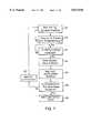
- FIG. 7is a flow chart of the algorithm used by the range determining device to monitor the amplitude of the Doppler in the first and second harmonic components of the modulation signal of the Doppler signal to determine that a collision is imminent;
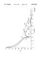
- FIG. 8is a graphic representation of the typical variation of amplitudes with respect to range of the Doppler in the first, second and DC harmonic components relative to each other;
- FIG. 9is a flow chart of the velocity measurement steps taken by the velocity measurement device according to this invention.
- FIG. 10is a graphic representation of g force sensor signals for low, medium and high speed collisions illustrating the various firing points that could be chosen sooner after impact with the anticipatory object detection system of this invention compared to firing points based on actual collision with the object.
- FIG. 1A simplified block diagram of the multi-sensor anticipatory object detection system according to this invention is shown in FIG. 1.
- a first transducer device 18a and a second transducer device 18beach of which transmits a modulated carrier signal, such as a radar signal.
- a modulated carrier signalsuch as a radar signal.
- two sensorsare sufficient given the width of a standard automobile, it is possible to use as many sensors as necessary, e.g. 18c, 18d . . .
- the signalis reflected by a potential colliding object and the reflected signal is received by the first transducer device 18a and second transducer device 18b.
- a detection device 22contains two detection circuits, one associated with each transducer.
- Detection device 22mixes the reflected modulated carrier signal with the modulated carrier signal to produce a composite Doppler shifted signal comprised of many different signals to include the Doppler shifted harmonic components of each reflected modulation signal: because there are multiple transducer devices, there is a reflected modulation signal associated with each transducer device. Thus, detection device 22 detects the Doppler shifted harmonic components of the modulation signal associated with each transducer device. There is associated with each harmonic component, a Doppler. Due to the Doppler effect the reflected modulation signal differs from the modulation signal by the Doppler frequency.
- the Dopplerwhich is the envelope of the individual harmonic components, has a frequency equal to the Doppler frequency and an amplitude equal to the amplitude of the individual harmonic component with which it is associated.
- Detection device 22extracts the Doppler of predetermined harmonic components.
- the harmonic components of interestare the first harmonic component, second harmonic component and DC harmonic component of the modulation signal associated with each transducer device.
- a range determining device 24includes two range determining circuits which monitor the amplitudes of the Doppler of the harmonic components associated with each reflected modulation signal looking for predetermined relationships between the Doppler of each harmonic component. Because there are multiple transducers, an object will typically be detected by one transducer device before the other. The transducer device that detects the object first will determine the software that is used to track the object. When the object reaches a predetermined range with respect to the near transducer device, the instantaneous range of the object is known. This is discussed further in FIG. 3. Once this range is known, velocity measurement device 26 determines the instantaneous velocity of the object with respect to the near transducer device.
- Velocity measurement device 26contains at least two velocity determining circuits, one associated with each transducer. The relative velocity is derived from the frequency of one of the harmonic components associated with that transducer device: velocity measurement device 26 produces a Doppler pulse associated with each reflected signal derived from one of the harmonic components. Range determining device 24 monitors the Doppler pulse thereafter, to track the instantaneous range of the object. As the object continues on its collision path, it is detected by the distant sensor, again at a predetermined range. Because the near sensor continuously tracks the instantaneous range of the object, once the distant sensor detects the object, the range of the object with respect to both the distant sensor and the near sensor is known, and so the position of the object can be triangulated.
- the angle of impactcan be determined based on the normal component of the velocity. Having determined the angle of impact, the actual point of impact can be determined.
- a fire signalis sent prior to impact to decision device 20 which is part of an existing restraint system.
- a conventional g force sensor 30sends a fire signal to decision device 20 upon impact with the object.
- Decision device 20then signals passenger restraint system 32 to fire the airbag well prior to the time the "g" sensor can determine collision has occurred.
- the actual amplitudes of the first and second harmonic components of the modulation signalare illustratively depicted by waveforms 23 and 25, respectively, FIG. 2.
- the harmonic components of the modulation signalpeak at fixed distances for a given bandwidth of the carrier signal independent of frequency.
- the first harmonic component 23 of the modulation signalhas a peak 27 at 5 feet.
- the second harmonic component 25 of the modulation signalhas a peak 29 at 10 feet.
- the point at which the two harmonic components intersect 134is 1/2 the distance between the peaks, or 7.5 feet and is known as a range bin crossing.
- the instantaneous range of the objectis known.
- the distances at which the amplitudes peakcan be directly controlled by the bandwidth of the carrier signal. For example, a carrier signal having a bandwidth of 200 MHz would have a first harmonic component of the modulation signal peak at 2.5 feet and the second harmonic component would peak at 5 feet.
- the range of an objectcan be detected based solely on the bandwidth of the carrier signal regardless of the frequency of either the carrier signal or the modulation signal.
- the instantaneous range of an objectcan be tracked by counting the Doppler pulses from that point on: at 5.8 GHz each Doppler cycle represents the relative movement of the object in one inch increments.
- the range detectedis the radial distance from the sensor. It should be noted that the intersection may be adjusted as well by introducing delay in the system or amplifying the signals.
- the manner of triangulating the position of a colliding objectcan be understood more clearly by referring to FIG. 3 and FIG. 4.
- a first range bin crossing and a second range bin crossingare detected, both known distances.
- the first range bin crossingyields the range of the object with respect to one sensor.
- the second range bin crossingyields the range of the object with respect to the second sensor.
- Subtracting from the first range bin crossing the distance travelled to the second range bin crossingyields the range of the object with respect to the first sensor at a time when the range of the object with respect to the second sensor is also known.
- knowing the range of the object with respect to two sensors separated by a fixed distancepermits an oblique triangle to be defined.
- the use of simple trigonometryyields the angle formed by the headings of the object to each sensor and the angle formed by the heading of the object to the first sensor and the vehicle. Knowing the relative velocity of the object with respect to each sensor (as measured by each sensor) and using the angles found above, the normal component of the velocity of the object with respect to the vehicle is determined. The angle at which the object will impact the vehicle is found, again using simple trigonometry, using the normal and tangential components of the velocity of the object. Finally, once the angle of impact is known, the point of impact is determined. Typically, an object will be detected by one sensor before it is detected by the other sensor.
- An automobile 10, FIG. 3,is equipped with a first sensor 16a which acts as a slave and a second sensor 16b which acts as a master.
- An objectis detected first by the slave sensor.
- the master sensorperforms the same calculations as the slave plus it performs oversight and control functions regardless of which sensor detects the object first.
- the sensor which detects an object firstdetermines which calculation software is accessed.
- Arcs 134a and 134brepresent the range bin crossing: the point at which the Doppler of the first and second harmonic components of the reflected modulated signal associated with sensors 16a and 16b, respectively, intersect, as discussed in FIG. 2. As discussed above, this distance is a known distance and is the same for both sensors. It can be varied but is typically set to 4.5 feet and is based on the standard width of an automobile. The range of each sensor is chosen so that it is just beyond the distant edge of the bumper.
- An object 43 traveling along a path 142is first detected by first sensor 16a.
- first sensor 16aWhen crossing 134a is detected by first sensor 16a, the instantaneous range of object 43 is known.
- the first sensordetects a range bin crossing, it sends an 8 bit word to second sensor 16b. This informs second sensor 16b that a crossing 134a has occurred.
- the first sensor 16athen sends a 16 bit word to the second sensor for every Doppler pulse received.
- the 16 bit wordcontains the captured counter value, discussed in greater detail in FIG. 5.
- range determining device 22, FIG. 1counts the Doppler pulses associated with the reflected modulation signal received by first sensor 16a.
- the second sensor 16bincrements a variable counter for every 16 bit word received from first sensor 16a.
- the second sensor 16bWhen the second sensor 16b detects crossing 134b, it is known how many Doppler pulses it has received, and therefore can determine the radial distance that the object has traveled with respect to first sensor 16a.
- velocity measurement device 26FIG. 1 calculates the velocity of the object 43 relative to the second sensor 16b.
- Microprocessor 94aFIG. 5, simultaneously calculates the velocity relative to sensor 16a using the 16 bit captured counter value received from sensor 16a.
- the first sensor 16awaits a confirmation distance and sends a "1" to second sensor 16b to confirm that a collision is imminent.
- the radial distance, or headings, from the object 43 to second sensor 16b and first sensor 16aform an angle ⁇ .
- the distance from second sensor 16b to the object 43is known from the crossing 134b, as discussed in FIG. 2, and the distance D between the two sensors is known.
- the distance from the object 43 to first sensor 16adetermining device from the distance to crossing 134a.
- the velocity of the object 43 relative to first sensor 16a, or slavecan be found by:
- the velocity relative to second sensor 16b, or mastercan be found by:
- the collision point (d)is zero. If the collision is towards the second sensor, the offset distance is positive and likewise, if the collision is closer to the first sensor then d is negative. All of the above calculations may be calculated by the microprocessor. However, this not only adds to the cost and complexity of the microprocessor, but adds to the time necessary to perform the calculations. Reducing this time could be accomplished, but again, would add to the cost of the microprocessor. Given the standard width of an automobile is typically 4.5-5.0 feet, there are only a finite number points at which an object may impact the front bumper.
- first sensor 16adoes not confirm the collision, it sends a "2" to second sensor 16b indicating that no collision is imminent. If both sensors do not confirm an imminent collision, the system resets and continues to monitor for potential colliding objects, waiting to detect crossings 134a or 134b. If either sensor confirms, a collision is imminent.
- FIG. 4there is shown in an automobile 10 equipped with a first sensor 16a which still acts as a slave and a second sensor 16b which still acts as a master.
- Arcs 134a' and 134b'represent the range bin crossings as discussed in FIG. 3.
- An object 43' traveling along a path 142'is first detected by second sensor 16b.
- crossing 134b'is detected by second sensor 16b, the instantaneous range of object 43' is known.
- range determining device 22, FIG. 1counts the Doppler pulses associated with the reflected modulation signal received by second sensor 16b.
- velocity measurement device 26calculates the velocity of the object 43' relative to the first sensor 16a.
- Microprocessor 94a, FIG. 5simultaneously calculates the velocity relative to sensor 16b using the 16 bit captured counter value received from sensor 16b.
- the radial distance from first sensor 16a and second sensor 16b to the object 43'form an angle ⁇ .
- the distance from first sensor 16a to the object 43'is known from the crossing 134a', and the distance between the two sensors D is known.
- the distance from the object 43' to second sensor 16bis determined by subtracting 1/2 the number of Doppler pulses counted by the range determining device from the distance to crossing 134b'. Knowing the length of all three sides of the oblique triangle, it is possible to determine ⁇ and ⁇ using equations 9 and 10 below: ##EQU5##
- a look up tableis used to actually determine the impact point.
- FIG. 5A more detailed schematic of an individual sensor is shown in FIG. 5. As each sensor is identical, the discussion of FIG. 5 will be directed to sensor 16a.
- the means of communication between the sensorsis unidirectional serial communication.
- Slave sensor 16acommunicates to master sensor 16b (not shown) which communicates to passenger restraint system 32, which in turn is connected back to sensor 16a, closing the loop.
- Transducer device 18aincludes a voltage controlled oscillator 40a which generates a carrier signal having a center frequency of 5.8 GHz. In order to remain within FCC guidelines for unlicensed sensor operation, the bandwidth of the signal must be such that the carrier signal stays within the range of 5.725 GHz to 5.875 GHz.
- the carrier signalis modulated at a frequency of 156.25 KHz.
- the frequency range, or bandwidth, of voltage controlled oscillator 40ais dictated by the changes in amplitude of the modulation signal.
- the modulation frequencyis typically chosen to be at least ten times larger than the Doppler frequency. It must be of sufficient frequency such that leakage throughout the system will not affect the Doppler frequency.
- a circulator 36adelivers the modulated carrier signal to antenna 42a.
- Antenna 42atransmits the modulated 5.8 GHz carrier signal, which is reflected off objects within a predetermined range, typically from two to ten feet away to just beyond the bumper. The reflected signal is then received by antenna 42a.
- the transducer device of the preferred embodimentis provided in a single MMIC radar chip manufactured by Hittite Corporation of Massachusetts and includes a single transmit/receive antenna. However, independent transmit and receive antennas may be used. It is important, however, that a broad beam antenna is used to provide sufficient field view of the system.
- Detection circuit 22abeats the received signal with the modulated carrier signal using mixer 44a.
- the local oscillator for mixer 44ais provided by the leakage of the modulated carrier signal from circulator 36a.
- Mixer 44aproduces a beat frequency, or composite Doppler signal, which is the frequency difference between the modulated carrier signal and the received reflected signal associated with sensor 16a.
- the composite Doppler signalis comprised of a plurality of signals to include the harmonic components of the reflected modulation frequency. The frequency of the harmonics of the modulation frequency present in the composite Doppler signal differ from the modulation frequency by the Doppler frequency.
- the harmonic components of interestare the first harmonic component, second harmonic component and the DC harmonic component of the modulation signal.
- Detection circuit 22acontains a plurality of signal paths 52a, 54a, and 56a which deliver the Doppler shifted harmonic components to a plurality of channels 70a, 72a, and 74a respectively, for extracting the Doppler from the harmonic components.
- channel 70acontains a mixer 48a which mixes the Doppler shifted first harmonic component, represented by waveform 76 as shown in FIG. 6A, with the modulation signal, 156.25 KHz: envelope 77 represents the Doppler frequency while the first harmonic is represented by waveform 79.
- Channel 70aalso includes a Doppler amplifier 58a which includes a pulse shaping circuit that amplifies and rectifies the first Doppler.
- This signalis represented by waveform 81 as shown in FIG. 6C.
- This signalhas the frequency of the Doppler frequency and the amplitude represents the variations of the first harmonic component of the modulation signal of the reflected signal.
- the Doppler amplifier 58asupplies the amplified, rectified, first Doppler to a range determining circuit 24a.
- Range determining circuit 24aincludes a peak detector 68 which includes an RC network which produces a DC voltage as illustrated by waveform 80 in FIG. 6D.
- channel 72acontains a mixer 50a which mixes the Doppler shifted second harmonic component, represented by waveform 78 as shown in FIG. 6B, with a signal which is twice the frequency of the modulation signal, 312.5 KHz. This demodulation produces the Doppler of the second harmonic component, or second Doppler, of the modulation signal.
- Channel 72aalso contains Doppler amplifier 60a which includes a pulse shaping circuit that amplifies and rectifies the second Doppler. This signal is similar to that illustrated by waveform 81 in FIG. 6C.
- the amplified, rectified second Doppleris then delivered to range determining circuit 24a.
- Range determining circuit 24aincludes a peak detector 66a, similar to peak detector 68a, which produces a DC voltage output similar to that illustrated by waveform 80 of FIG. 6D.
- Channel 74aincludes a Doppler amplifier 62a which amplifies and rectifies the Doppler signal to produce the Doppler of the direct current (DC) or fundamental harmonic component, or DC Doppler, of the reflected modulation signal.
- the DC Doppleris delivered to peak detector 64a, similar to peak detectors 66a and 68a, to produce a DC voltage similar to waveform 80 of FIG. 6D.
- the DC voltage signals of the first Doppler, second Doppler, and DC Dopplerare delivered to an analog to digital converter 90a via signal paths 84a, 86a and 88a respectively.
- Analog to digital converter 90aconverts the DC voltages to digital signals which it then supplies to a microprocessor 94a via signal bus 92a.
- Microprocessor 94athrough the implementation of software discussed below, monitors the Doppler amplitude of each harmonic component and its relationship with the Doppler amplitudes of the other harmonic components to determine the instantaneous range of an object. The instantaneous range is determined using intersection of the first and second Doppler amplitudes.
- the amplitude, phase, and relative Doppler sideband character of each of the harmonic componentsare a function of object range, relative velocity magnitude and sense, and peak to peak frequency deviation.
- Velocity measurement circuit 26aincludes a comparator device 96a.
- comparator 96ais connected to the output of channel 70a of detection circuit 22a since the first harmonic component has the greatest amplitude. However, comparator 96a may be placed at the output of either channel 72a or 74a.
- Comparator 96areceives the amplified, rectified first Doppler and compares the level of that output to a predetermined value. If the level of the input exceeds a predetermined value, comparator 96a outputs a high signal. If the input does not exceed the predetermined value, comparator 96 outputs a low value. The resulting output, a series of Doppler pulses illustrated by waveform 82 as shown in FIG.
- Velocity measurement circuit 26aincludes a velocity measurement circuit having an accumulator device 100a, such as a capture register, which is driven by the Doppler pulse supplied over signal path 98a. Velocity measurement circuit 26a also includes a counter device 102a interconnected with accumulator device 100a via signal bus 97a. Counter device 102a, driven by an internal 5 MHz clock, continuously counts the cycles of the 5 MHz clock. With every rising edge of the Doppler pulse from comparator 96a, accumulator device 100a sends an interrupt to microprocessor 94a, a portion of which is shared with range determining circuit 24a, and simultaneously reads counter device 102a and stores the number of cycles counted.
- accumulator device 100aWith every rising edge of the Doppler pulse from comparator 96a, accumulator device 100a sends an interrupt to microprocessor 94a, a portion of which is shared with range determining circuit 24a, and simultaneously reads counter device 102a and stores the number of cycles counted.
- microprocessor 94aWith every interrupt received by microprocessor 94a from accumulator device 100a microprocessor 94a reads the cycle count stored in accumulator device 100a, resets counter device 102a and increments a Doppler count by 1.
- the Doppler countrepresents the number of Doppler pulses received.
- velocity measurement circuit 26acounts the number of 5 MHz clock pulses that occur for each Doppler pulse. Since the Doppler pulse is derived from a rectified Doppler component, each pulse represents one half Doppler cycle. The process is repeated with each rising edge of the Doppler pulse, each 5 MHz cycle count being added to the previous cycle count stored in microprocessor 94a, until the Doppler count is equal to 4.
- the microprocessor 94adiscontinues reading accumulator device 100a and divides by 4 the total count stored to provide an average 5 MHz cycle count. Microprocessor 94a then refers to a look up table to determine what velocity is associated with that average count. While there are many ways the velocity may be calculated, the look up table provides a fast and accurate method without tying up the microprocessor. Accumulator device 100a continues to send an interrupt to microprocessor 94a with every rising edge of the Doppler pulse. Although the microprocessor no longer reads accumulator device 100a, with every interrupt it receives from accumulator device 100a, microprocessor 94a continues to increment the Doppler count and sends a signal to sensor 16b.
- the Doppler countrepresents the number of Doppler pulses received, each pulse being equivalent to 0.5 inches of relative movement by the object; each Doppler cycle is one half the wavelength of the 5.8 GHz carrier signal.
- microprocessor 94aWhile the velocity is being determined, microprocessor 94a, a portion of which is included in an impact decision circuit 28a, continues to monitor the amplitude of the Doppler. When impact decision circuit 28a has determined that a collision is imminent, a signal is sent to sensor 16a (not shown).
- microprocessor 94a, analog to digital converter 90a, counter device 102a and accumulator device 100aare contained in a single chip, Model PIC16C74, available from Microchip of Chandler, Ariz.
- microprocessor 94amonitors the amplitude of the second Doppler, K2, to determine when it exceeds a predetermined threshold value. Once this threshold value has been exceeded the microprocessor monitors the difference between K2 and the amplitude of the first Doppler, K1, to determine whether that difference exceeds a second threshold value, block 112. If that second threshold value is not exceeded, the software returns to block 110 continuing to monitor K2. However, if the difference between the two harmonic components exceeds the second threshold value, microprocessor 94a, FIG.
- the K1 and K2 componentsare compared to determine whether the K1 component exceeds K2 by a predetermined difference, block 120, which difference represents the difference that would occur in an actual collision given the same velocity. If that difference is detected, a signal is sent to sensor 16b. If K1 does not exceed K2 by a predetermined difference, block 120, a no confirmation signal is sent, block 122, which indicates that no collision will occur, and the slave microprocessor returns to monitoring K2, block 110.
- the master sensormonitors the harmonics in a similar fashion once a range bin crossing has been detected, except that the master communicates directly with the passenger restrain system. For example, rather than send confirmation information the master sends a fire signal, or a no fire signal.
- FIG. 8An example of the Doppler amplitudes each microprocessor is looking for is illustrated in FIG. 8.
- the microprocessormonitors the difference between the amplitudes of the second Doppler 124 and the first Doppler 128 until there is detected a second threshold value 132, which represents the predetermined difference. Once this second threshold value 132 is detected, the microprocessor monitors the amplitude of the second Doppler 124 and the amplitude of the first Doppler 126 to detect when the amplitudes are equal. This is represented by crossing 134.
- the microprocessormonitors the amplitude of the second Doppler 124 and the amplitude of the first Doppler 126 for a confirmation distance 138.
- This confirmation distanceis generally equal to the distance from the sensor system to just beyond the edge of the automobile.
- the microprocessorhas waited for the confirmation distance 138 it compares the amplitude of the second Doppler 124 with the amplitude of the first Doppler 126 looking for a predetermined difference 136 which represents the difference which would occur in an actual collision.
- microprocessor 94FIG. 5, determines that a collision is imminent and sends a confirmation signal.
- amplification of the Doppler componentscan be used to vary their relationships with each other and thus shift crossing 134 to a desired distance as well as confirmation distance 138.
- This simple gain adjustment using amplifiers 58a-62aprovides a degree of freedom for various pre-crash sensing applications where a single sensor is mounted in the center of a bumper of the automobile. Because the typical width of an automobile is 4 to 5 feet, the decision must be made just beyond the edge of the automobile so as not to induce false alarms. Thus, the system can be easily adapted for any size automobile.
- the speed calculationis initiated, block 146, FIG. 9.
- the microprocessor of the master sensorwaits for an accumulator interrupt, block 148, and resets the counter saving the accumulator value, block 150.
- a Doppler countis incremented, block 152, and compared to determine whether it is greater than four, block 154. If the Doppler count does not exceed four the routine returns to block 148 and waits for the next interrupt. However, if the Doppler count is greater than four, the microprocessor divides by four the total number of 5 MHz cycles counted to obtain an average clock cycle over four readings of the 5 MHz clock, block 156.
- the microprocessorsimultaneously averages the last four 16 bit words received from the slave sensor to obtain an average count with respect to the slave sensor.
- the microprocessorcompares each average clock cycle count to a lookup table to determine the relative velocity of the object with respect to each sensor, block 158.
- the microprocessordiscontinues reading the accumulator device, but increments the Doppler count with each interrupt received from the accumulator counting Doppler pulses until the confirmation distance has been reached, block 160.
- Firing points 170, 172 and 174correspond to typical points during a crash event at which the g sensor will send a fire signal to the passenger restraint system for low speed 162, medium speed 166, and high speed 168 collisions, respectively, based on the g forces the automobile is actually undergoing.
- firing points 176, 178 and 180represent the firing points for low speed 162, medium speed 166 and high speed 168 collisions as determined by the anticipatory collision sensor system according to this invention.
- the passenger restraint systemmay fire at a point 176 which is much earlier in the crash event than the typical firing point 170 as determined by the g force sensor.
- the anticipatory collision sensor systemcan determine the severity of the collision, based on the relative velocity of the object, at a point in time 176 before the collision takes place. This reduces the time to fully deploy the airbag, thereby allowing full deployment of the airbag before the occupants have shifted position due to the collision. This allows the passenger to remain at a safer distance from the airbag as it inflates.
- firing points 176, 178 and 180are based on the relative velocity of the object and the distance of the object and are not arbitrary firing points.
Landscapes
- Engineering & Computer Science (AREA)
- Radar, Positioning & Navigation (AREA)
- Remote Sensing (AREA)
- Physics & Mathematics (AREA)
- Mechanical Engineering (AREA)
- Computer Networks & Wireless Communication (AREA)
- General Physics & Mathematics (AREA)
- Electromagnetism (AREA)
- Radar Systems Or Details Thereof (AREA)
Abstract
Description
v.sub.s =v.sub.x sin(β)-v.sub.y cos(β) (3)
v.sub.m =v.sub.x sin(α+β)-v.sub.y cos(α+β)(4)
Claims (41)
Priority Applications (4)
| Application Number | Priority Date | Filing Date | Title |
|---|---|---|---|
| US08/808,939US5872536A (en) | 1997-02-19 | 1997-02-19 | Multi-sensor anticipatory object detection system |
| JP53695698AJP3236025B2 (en) | 1997-02-19 | 1998-02-17 | Multi-sensor type object prediction detection system |
| PCT/US1998/003523WO1998037435A1 (en) | 1997-02-19 | 1998-02-17 | Multi-sensor anticipatory object detection system |
| EP98906657AEP0961939A4 (en) | 1997-02-19 | 1998-02-17 | Multi-sensor anticipatory object detection system |
Applications Claiming Priority (1)
| Application Number | Priority Date | Filing Date | Title |
|---|---|---|---|
| US08/808,939US5872536A (en) | 1997-02-19 | 1997-02-19 | Multi-sensor anticipatory object detection system |
Publications (1)
| Publication Number | Publication Date |
|---|---|
| US5872536Atrue US5872536A (en) | 1999-02-16 |
Family
ID=25200169
Family Applications (1)
| Application Number | Title | Priority Date | Filing Date |
|---|---|---|---|
| US08/808,939Expired - LifetimeUS5872536A (en) | 1997-02-19 | 1997-02-19 | Multi-sensor anticipatory object detection system |
Country Status (4)
| Country | Link |
|---|---|
| US (1) | US5872536A (en) |
| EP (1) | EP0961939A4 (en) |
| JP (1) | JP3236025B2 (en) |
| WO (1) | WO1998037435A1 (en) |
Cited By (49)
| Publication number | Priority date | Publication date | Assignee | Title |
|---|---|---|---|---|
| US6072421A (en)* | 1998-05-29 | 2000-06-06 | Mitsubishi Denki Kabushiki Kaisha | Moving object high-accuracy position locating method and system |
| US6104284A (en)* | 1998-06-19 | 2000-08-15 | Toyota Jidosha Kabushiki Kaisha | Roll over determining method |
| US6121799A (en)* | 1999-04-29 | 2000-09-19 | Tektronix, Inc. | Interleaved digital peak detector |
| DE19934670A1 (en)* | 1999-05-26 | 2000-12-21 | Bosch Gmbh Robert | Object detection system |
| US6225891B1 (en) | 2000-01-07 | 2001-05-01 | Hittite Microwave Corp. | Wide-angle, static and positional anticipatory object detection system |
| US6271747B1 (en)* | 1998-04-18 | 2001-08-07 | Daimlerchrysler Ag | Method for adjusting the trigger threshold of vehicle occupant protection devices |
| WO2002030716A1 (en) | 2000-10-10 | 2002-04-18 | Daimlerchrysler Ag | Method and device for activating passenger protection device |
| US6434461B1 (en)* | 1998-01-28 | 2002-08-13 | Daimlerchrysler Ag | Airbag sensor system |
| US6498972B1 (en) | 2002-02-13 | 2002-12-24 | Ford Global Technologies, Inc. | Method for operating a pre-crash sensing system in a vehicle having a countermeasure system |
| US20030023361A1 (en)* | 2001-07-17 | 2003-01-30 | Makoto Umeda | System to monitor course of a matter going to collide and safety device against clash for a motorcycle which device using the system |
| US6519519B1 (en) | 2002-02-01 | 2003-02-11 | Ford Global Technologies, Inc. | Passive countermeasure methods |
| US20030076981A1 (en)* | 2001-10-18 | 2003-04-24 | Smith Gregory Hugh | Method for operating a pre-crash sensing system in a vehicle having a counter-measure system |
| US6580385B1 (en) | 1999-05-26 | 2003-06-17 | Robert Bosch Gmbh | Object detection system |
| US20030139864A1 (en)* | 2002-01-24 | 2003-07-24 | Ford Global Technologies, Inc. | Post collision restraints control module |
| US20030142007A1 (en)* | 2001-03-15 | 2003-07-31 | Daisaku Ono | Signal processing method for scanning radar |
| US6721659B2 (en) | 2002-02-01 | 2004-04-13 | Ford Global Technologies, Llc | Collision warning and safety countermeasure system |
| US20040111200A1 (en)* | 2001-11-29 | 2004-06-10 | Rao Manoharprasad K. | Vehicle sensing based pre-crash threat assessment system |
| US20040117115A1 (en)* | 2001-12-07 | 2004-06-17 | Uwe Zimmermann | Method for identifying obstacles for a motor vehicle, using at least three distance sensors for identifying the laterla extension of an object |
| WO2004059341A1 (en)* | 2002-12-20 | 2004-07-15 | Daimlerchrysler Ag | Method for detecting environmental information and for determining the position of a parking space |
| US6775605B2 (en) | 2001-11-29 | 2004-08-10 | Ford Global Technologies, Llc | Remote sensing based pre-crash threat assessment system |
| US6831572B2 (en) | 2002-01-29 | 2004-12-14 | Ford Global Technologies, Llc | Rear collision warning system |
| US20050024501A1 (en)* | 1996-05-22 | 2005-02-03 | John Ellenby | Method and apparatus for controlling the operational mode of electronic devices in response to sensed conditions |
| EP1566657A2 (en) | 2004-02-18 | 2005-08-24 | Delphi Technologies, Inc. | Collision detection system and method of estimating target crossing location |
| US7009500B2 (en) | 2002-02-13 | 2006-03-07 | Ford Global Technologies, Llc | Method for operating a pre-crash sensing system in a vehicle having a countermeasure system using stereo cameras |
| WO2006045668A1 (en)* | 2004-10-29 | 2006-05-04 | Robert Bosch Gmbh | Sensor system for motor vehicles including fmcw radar sensors for measuring distance to an object in an angle-resolved manner by means of triangulation |
| US20060173621A1 (en)* | 2004-03-31 | 2006-08-03 | Lawrence Stopczynski | Collision mitigation system |
| WO2006089841A1 (en)* | 2005-02-25 | 2006-08-31 | Robert Bosch Gmbh | Motor vehicle radar system provided with an automatic function for measuring pre-crash speed |
| US20070252656A1 (en)* | 2006-04-17 | 2007-11-01 | Fred Mirow | Variable loop gain oscillator system |
| US20080123480A1 (en)* | 2006-07-05 | 2008-05-29 | Samsung Electronics Co., Ltd. | Disturbance compensation determination apparatus, a related method, a computer-readable medium storing a computer program related to the method, and a disk drive comprising the apparatus |
| US20080174474A1 (en)* | 2006-11-01 | 2008-07-24 | Imsar | Interferometric switched beam radar apparatus and method |
| US20080204306A1 (en)* | 2007-02-27 | 2008-08-28 | Fujitsu Limited | Detecting and ranging apparatus and detecting and ranging program product |
| US20090141592A1 (en)* | 2007-12-03 | 2009-06-04 | Kolo Technologies, Inc. | Telemetric Sensing Using Micromachined Ultrasonic Transducer |
| US20100097264A1 (en)* | 2008-10-21 | 2010-04-22 | Toyota Jidosha Kabushiki Kaisha | Radar apparatus |
| US20100246332A1 (en)* | 2007-12-03 | 2010-09-30 | Kolo Technologies, Inc. | Stacked Transducing Devices |
| US20100262014A1 (en)* | 2007-12-03 | 2010-10-14 | Yongli Huang | Ultrasound Scanner Built with Capacitive Micromachined Ultrasonic Transducers (CMUTS) |
| US20100275690A1 (en)* | 2009-05-04 | 2010-11-04 | Miroslaw Wrobel | Method For Examining A Medium |
| US20110285576A1 (en)* | 2007-01-25 | 2011-11-24 | Lynam Niall R | Forward facing sensing system for a vehicle |
| EP2442133A1 (en)* | 2010-10-18 | 2012-04-18 | Raytheon Company | Systems and methods for collision avoidance in unmanned aerial vehicles |
| US20120106291A1 (en)* | 2009-05-13 | 2012-05-03 | Albrecht Klotz | Method for functional testing of an ultrasonic sensor on a motor vehicle, method for operating an ultrasonic sensor on a motor vehicle, and distance measuring device having at least one ultrasonic sensor for use in a motor vehicle |
| US20120154173A1 (en)* | 2010-12-15 | 2012-06-21 | Tsai-Wang Chang | Wireless Signal Transceiver and Blind Spot Detection System |
| DE102011012379A1 (en)* | 2011-02-23 | 2012-08-23 | S.M.S Smart Microwave Sensors Gmbh | Method and radar sensor arrangement for detecting location and speed of objects relative to a vehicle |
| JP2013221785A (en)* | 2012-04-13 | 2013-10-28 | Japan Radio Co Ltd | Radar signal processing apparatus |
| US20150085612A1 (en)* | 2012-01-19 | 2015-03-26 | Matthias Karl | Method and driving-environment sensor for determining the position and/or the movement of at least one object in the vicinity of a vehicle on the basis of acoustic signals reflected off of the object |
| US20150142247A1 (en)* | 2013-11-20 | 2015-05-21 | Ford Global Technologies, Llc | Dual airbags in vehicle with reconfigurable interior |
| US20160003943A1 (en)* | 2013-03-04 | 2016-01-07 | Panasonic Intellectual Property Management Co. Ltd. | Obstacle detection device for vehicle and obstacle detection system for vehicle |
| CN105313817A (en)* | 2014-08-01 | 2016-02-10 | 福特全球技术公司 | Dual airbags in vehicle with reconfigurable interior |
| US10473759B2 (en)* | 2017-03-28 | 2019-11-12 | GM Global Technology Operations LLC | Tool for automatic multiple radar calibration |
| US11022511B2 (en) | 2018-04-18 | 2021-06-01 | Aron Kain | Sensor commonality platform using multi-discipline adaptable sensors for customizable applications |
| US20230088015A1 (en)* | 2021-09-17 | 2023-03-23 | Shenzhen Reolink Technology Co., Ltd. | Range-finding method, range-finding apparatus, range-finding system, and non-transitory computer-readable storage medium |
Families Citing this family (2)
| Publication number | Priority date | Publication date | Assignee | Title |
|---|---|---|---|---|
| JP4994412B2 (en)* | 2009-03-30 | 2012-08-08 | 三菱電機株式会社 | Radar equipment |
| CN119413387B (en)* | 2024-11-22 | 2025-06-10 | 苏州明远汽车零部件制造有限公司 | A multi-point impact detection device for automobile airbags |
Citations (11)
| Publication number | Priority date | Publication date | Assignee | Title |
|---|---|---|---|---|
| US3832709A (en)* | 1972-12-26 | 1974-08-27 | Johnson Service Co | Motion detection apparatus having the ability to determine the direction of motion and range of a moving object |
| US3860923A (en)* | 1972-04-08 | 1975-01-14 | Toyota Motor Co Ltd | Vehicle collision anticipating device |
| US3864678A (en)* | 1972-04-08 | 1975-02-04 | Toyoda Chuo Kenkyusho Kk | Vehicle collision anticipating device |
| US3893114A (en)* | 1972-04-08 | 1975-07-01 | Toyota Motor Co Ltd | Method and device for anticipating a collision |
| US3952303A (en)* | 1973-02-15 | 1976-04-20 | Matsushita Electric Industrial Co., Ltd. | Doppler radar for forecasting collision |
| US3974501A (en)* | 1974-12-26 | 1976-08-10 | Rca Corporation | Dual-mode adaptive parameter processor for continuous wave radar ranging systems |
| US4003049A (en)* | 1975-07-03 | 1977-01-11 | Rca Corporation | Dual mode automobile collision avoidance radar |
| US4008473A (en)* | 1973-01-20 | 1977-02-15 | Nippon Soken, Inc. | Collision predicting operation system |
| US5517196A (en)* | 1992-08-14 | 1996-05-14 | Pakett; Allan G. | Smart blind spot sensor with object ranging |
| US5638281A (en)* | 1991-01-31 | 1997-06-10 | Ail Systems, Inc. | Target prediction and collision warning system |
| US5694130A (en)* | 1995-01-09 | 1997-12-02 | Honda Giken Kogyo Kabushiki Kaisha | Vehicle-mounted radar system and detection method |
- 1997
- 1997-02-19USUS08/808,939patent/US5872536A/ennot_activeExpired - Lifetime
- 1998
- 1998-02-17EPEP98906657Apatent/EP0961939A4/ennot_activeCeased
- 1998-02-17JPJP53695698Apatent/JP3236025B2/ennot_activeExpired - Fee Related
- 1998-02-17WOPCT/US1998/003523patent/WO1998037435A1/ennot_activeApplication Discontinuation
Patent Citations (11)
| Publication number | Priority date | Publication date | Assignee | Title |
|---|---|---|---|---|
| US3860923A (en)* | 1972-04-08 | 1975-01-14 | Toyota Motor Co Ltd | Vehicle collision anticipating device |
| US3864678A (en)* | 1972-04-08 | 1975-02-04 | Toyoda Chuo Kenkyusho Kk | Vehicle collision anticipating device |
| US3893114A (en)* | 1972-04-08 | 1975-07-01 | Toyota Motor Co Ltd | Method and device for anticipating a collision |
| US3832709A (en)* | 1972-12-26 | 1974-08-27 | Johnson Service Co | Motion detection apparatus having the ability to determine the direction of motion and range of a moving object |
| US4008473A (en)* | 1973-01-20 | 1977-02-15 | Nippon Soken, Inc. | Collision predicting operation system |
| US3952303A (en)* | 1973-02-15 | 1976-04-20 | Matsushita Electric Industrial Co., Ltd. | Doppler radar for forecasting collision |
| US3974501A (en)* | 1974-12-26 | 1976-08-10 | Rca Corporation | Dual-mode adaptive parameter processor for continuous wave radar ranging systems |
| US4003049A (en)* | 1975-07-03 | 1977-01-11 | Rca Corporation | Dual mode automobile collision avoidance radar |
| US5638281A (en)* | 1991-01-31 | 1997-06-10 | Ail Systems, Inc. | Target prediction and collision warning system |
| US5517196A (en)* | 1992-08-14 | 1996-05-14 | Pakett; Allan G. | Smart blind spot sensor with object ranging |
| US5694130A (en)* | 1995-01-09 | 1997-12-02 | Honda Giken Kogyo Kabushiki Kaisha | Vehicle-mounted radar system and detection method |
Cited By (103)
| Publication number | Priority date | Publication date | Assignee | Title |
|---|---|---|---|---|
| US20050024501A1 (en)* | 1996-05-22 | 2005-02-03 | John Ellenby | Method and apparatus for controlling the operational mode of electronic devices in response to sensed conditions |
| US20100185303A1 (en)* | 1996-05-22 | 2010-07-22 | Qualcomm Incorporated | Method and apparatus for controlling the operational mode of electronic devices in response to sensed conditions |
| US7696905B2 (en) | 1996-05-22 | 2010-04-13 | Qualcomm Incorporated | Method and apparatus for controlling the operational mode of electronic devices in response to sensed conditions |
| US9009505B2 (en) | 1996-05-22 | 2015-04-14 | Qualcomm Incorporated | Method and apparatus for controlling the operational mode of electronic devices in response to sensed conditions |
| US6434461B1 (en)* | 1998-01-28 | 2002-08-13 | Daimlerchrysler Ag | Airbag sensor system |
| US6271747B1 (en)* | 1998-04-18 | 2001-08-07 | Daimlerchrysler Ag | Method for adjusting the trigger threshold of vehicle occupant protection devices |
| US6072421A (en)* | 1998-05-29 | 2000-06-06 | Mitsubishi Denki Kabushiki Kaisha | Moving object high-accuracy position locating method and system |
| US6104284A (en)* | 1998-06-19 | 2000-08-15 | Toyota Jidosha Kabushiki Kaisha | Roll over determining method |
| US6121799A (en)* | 1999-04-29 | 2000-09-19 | Tektronix, Inc. | Interleaved digital peak detector |
| US6580385B1 (en) | 1999-05-26 | 2003-06-17 | Robert Bosch Gmbh | Object detection system |
| DE19934670A1 (en)* | 1999-05-26 | 2000-12-21 | Bosch Gmbh Robert | Object detection system |
| DE19934670B4 (en)* | 1999-05-26 | 2004-07-08 | Robert Bosch Gmbh | Object detection system |
| US6225891B1 (en) | 2000-01-07 | 2001-05-01 | Hittite Microwave Corp. | Wide-angle, static and positional anticipatory object detection system |
| US20030100983A1 (en)* | 2000-10-10 | 2003-05-29 | Wilfried Bullinger | Method and device for a activating passenger protection device |
| US6980097B2 (en) | 2000-10-10 | 2005-12-27 | Daimlerchrysler Ag | Method and device for activating passenger protection device |
| DE10049911B4 (en)* | 2000-10-10 | 2006-08-10 | Daimlerchrysler Ag | Method and device for activating occupant protection devices |
| WO2002030716A1 (en) | 2000-10-10 | 2002-04-18 | Daimlerchrysler Ag | Method and device for activating passenger protection device |
| US6900754B2 (en)* | 2001-03-15 | 2005-05-31 | Fujitsu Tem Limited | Signal processing method for use with scanning radar |
| US20030142007A1 (en)* | 2001-03-15 | 2003-07-31 | Daisaku Ono | Signal processing method for scanning radar |
| US20030023361A1 (en)* | 2001-07-17 | 2003-01-30 | Makoto Umeda | System to monitor course of a matter going to collide and safety device against clash for a motorcycle which device using the system |
| US6908103B2 (en)* | 2001-07-17 | 2005-06-21 | Makoto Umeda | System to monitor course of a moving object going to collide and safety device against crashes for a motorcycle which uses the system |
| US20030076981A1 (en)* | 2001-10-18 | 2003-04-24 | Smith Gregory Hugh | Method for operating a pre-crash sensing system in a vehicle having a counter-measure system |
| US6819991B2 (en) | 2001-11-29 | 2004-11-16 | Ford Global Technologies, Llc | Vehicle sensing based pre-crash threat assessment system |
| US6775605B2 (en) | 2001-11-29 | 2004-08-10 | Ford Global Technologies, Llc | Remote sensing based pre-crash threat assessment system |
| US20040111200A1 (en)* | 2001-11-29 | 2004-06-10 | Rao Manoharprasad K. | Vehicle sensing based pre-crash threat assessment system |
| US6947841B2 (en)* | 2001-12-07 | 2005-09-20 | Robert Bosch Gmbh | Method for identifying obstacles for a motor vehicle, using at least three distance sensors for identifying the lateral extension of an object |
| US20040117115A1 (en)* | 2001-12-07 | 2004-06-17 | Uwe Zimmermann | Method for identifying obstacles for a motor vehicle, using at least three distance sensors for identifying the laterla extension of an object |
| US7158870B2 (en) | 2002-01-24 | 2007-01-02 | Ford Global Technologies, Llc | Post collision restraints control module |
| US20030139864A1 (en)* | 2002-01-24 | 2003-07-24 | Ford Global Technologies, Inc. | Post collision restraints control module |
| US6831572B2 (en) | 2002-01-29 | 2004-12-14 | Ford Global Technologies, Llc | Rear collision warning system |
| US6721659B2 (en) | 2002-02-01 | 2004-04-13 | Ford Global Technologies, Llc | Collision warning and safety countermeasure system |
| US6519519B1 (en) | 2002-02-01 | 2003-02-11 | Ford Global Technologies, Inc. | Passive countermeasure methods |
| US7009500B2 (en) | 2002-02-13 | 2006-03-07 | Ford Global Technologies, Llc | Method for operating a pre-crash sensing system in a vehicle having a countermeasure system using stereo cameras |
| US6498972B1 (en) | 2002-02-13 | 2002-12-24 | Ford Global Technologies, Inc. | Method for operating a pre-crash sensing system in a vehicle having a countermeasure system |
| WO2004059341A1 (en)* | 2002-12-20 | 2004-07-15 | Daimlerchrysler Ag | Method for detecting environmental information and for determining the position of a parking space |
| US20050197770A1 (en)* | 2004-02-18 | 2005-09-08 | Schiffmann Jan K. | Collision detection system and method of estimating target crossing location |
| EP1566657A3 (en)* | 2004-02-18 | 2006-05-24 | Delphi Technologies, Inc. | Collision detection system and method of estimating target crossing location |
| US7369941B2 (en)* | 2004-02-18 | 2008-05-06 | Delphi Technologies, Inc. | Collision detection system and method of estimating target crossing location |
| EP1566657A2 (en) | 2004-02-18 | 2005-08-24 | Delphi Technologies, Inc. | Collision detection system and method of estimating target crossing location |
| US20060173621A1 (en)* | 2004-03-31 | 2006-08-03 | Lawrence Stopczynski | Collision mitigation system |
| US7197396B2 (en)* | 2004-03-31 | 2007-03-27 | Ford Global Technologies, Llc | Collision mitigation system |
| US20080150790A1 (en)* | 2004-10-29 | 2008-06-26 | Klaus Voigtlaender | Apparatus and Method for Angle-Resolved Determination of the Distance and Speed of an Object |
| US7764221B2 (en)* | 2004-10-29 | 2010-07-27 | Robert Bosch Gmbh | Apparatus and method for determination of a direction to an object |
| WO2006045668A1 (en)* | 2004-10-29 | 2006-05-04 | Robert Bosch Gmbh | Sensor system for motor vehicles including fmcw radar sensors for measuring distance to an object in an angle-resolved manner by means of triangulation |
| US7786926B2 (en) | 2005-02-25 | 2010-08-31 | Robert Bosch Gmbh | Radar system for motor vehicles |
| US20080291078A1 (en)* | 2005-02-25 | 2008-11-27 | Joerg Hilsebecher | Radar System for Motor Vehicles |
| WO2006089841A1 (en)* | 2005-02-25 | 2006-08-31 | Robert Bosch Gmbh | Motor vehicle radar system provided with an automatic function for measuring pre-crash speed |
| US20070252656A1 (en)* | 2006-04-17 | 2007-11-01 | Fred Mirow | Variable loop gain oscillator system |
| US7456700B2 (en)* | 2006-04-17 | 2008-11-25 | Fred Mirow | Variable loop gain oscillator system |
| US20080123480A1 (en)* | 2006-07-05 | 2008-05-29 | Samsung Electronics Co., Ltd. | Disturbance compensation determination apparatus, a related method, a computer-readable medium storing a computer program related to the method, and a disk drive comprising the apparatus |
| US7777982B2 (en)* | 2006-07-05 | 2010-08-17 | Samsung Electronics Co., Ltd. | Disturbance compensation determination apparatus, a related method, a computer-readable medium storing a computer program related to the method, and a disk drive comprising the apparatus |
| US7755533B2 (en)* | 2006-11-01 | 2010-07-13 | Imsar Llc | Interferometric switched beam radar apparatus and method |
| US20080174474A1 (en)* | 2006-11-01 | 2008-07-24 | Imsar | Interferometric switched beam radar apparatus and method |
| US10670713B2 (en)* | 2007-01-25 | 2020-06-02 | Magna Electronics Inc. | Forward sensing system for vehicle |
| US20160252612A1 (en)* | 2007-01-25 | 2016-09-01 | Magna Electronics Inc. | Forward facing sensing system for vehicle |
| US9244165B1 (en) | 2007-01-25 | 2016-01-26 | Magna Electronics Inc. | Forward facing sensing system for vehicle |
| US9335411B1 (en)* | 2007-01-25 | 2016-05-10 | Magna Electronics Inc. | Forward facing sensing system for vehicle |
| US20190056493A1 (en)* | 2007-01-25 | 2019-02-21 | Magna Electronics Inc. | Forward sensing system for vehicle |
| US9140789B2 (en)* | 2007-01-25 | 2015-09-22 | Magna Electronics Inc. | Forward facing sensing system for vehicle |
| US11815594B2 (en)* | 2007-01-25 | 2023-11-14 | Magna Electronics Inc. | Vehicular forward-sensing system |
| US20110285576A1 (en)* | 2007-01-25 | 2011-11-24 | Lynam Niall R | Forward facing sensing system for a vehicle |
| US20230110888A1 (en)* | 2007-01-25 | 2023-04-13 | Magna Electronics Inc. | Vehicular forward-sensing system |
| US11506782B2 (en)* | 2007-01-25 | 2022-11-22 | Magna Electronics Inc. | Vehicular forward-sensing system |
| US20210109212A1 (en)* | 2007-01-25 | 2021-04-15 | Magna Electronics Inc. | Vehicular forward-sensing system |
| US10877147B2 (en)* | 2007-01-25 | 2020-12-29 | Magna Electronics Inc. | Forward sensing system for vehicle |
| US20140104095A1 (en)* | 2007-01-25 | 2014-04-17 | Magna Electronics Inc. | Forward facing sensing system for vehicle |
| US8217830B2 (en)* | 2007-01-25 | 2012-07-10 | Magna Electronics Inc. | Forward facing sensing system for a vehicle |
| US8614640B2 (en)* | 2007-01-25 | 2013-12-24 | Magna Electronics Inc. | Forward facing sensing system for vehicle |
| US8294608B1 (en) | 2007-01-25 | 2012-10-23 | Magna Electronics, Inc. | Forward facing sensing system for vehicle |
| US9507021B2 (en)* | 2007-01-25 | 2016-11-29 | Magna Electronics Inc. | Forward facing sensing system for vehicle |
| US10107905B2 (en) | 2007-01-25 | 2018-10-23 | Magna Electronics Inc. | Forward facing sensing system for vehicle |
| US20130044021A1 (en)* | 2007-01-25 | 2013-02-21 | Magna Electronics Inc. | Forward facing sensing system for vehicle |
| US7692572B2 (en)* | 2007-02-27 | 2010-04-06 | Fujitsu Limited | Detecting and ranging apparatus and detecting and ranging program product |
| US20080204306A1 (en)* | 2007-02-27 | 2008-08-28 | Fujitsu Limited | Detecting and ranging apparatus and detecting and ranging program product |
| US8345513B2 (en) | 2007-12-03 | 2013-01-01 | Kolo Technologies, Inc. | Stacked transducing devices |
| US20100262014A1 (en)* | 2007-12-03 | 2010-10-14 | Yongli Huang | Ultrasound Scanner Built with Capacitive Micromachined Ultrasonic Transducers (CMUTS) |
| US20090141592A1 (en)* | 2007-12-03 | 2009-06-04 | Kolo Technologies, Inc. | Telemetric Sensing Using Micromachined Ultrasonic Transducer |
| US8767514B2 (en)* | 2007-12-03 | 2014-07-01 | Kolo Technologies, Inc. | Telemetric sensing using micromachined ultrasonic transducer |
| US20100280388A1 (en)* | 2007-12-03 | 2010-11-04 | Kolo Technologies, Inc | CMUT Packaging for Ultrasound System |
| US9408588B2 (en) | 2007-12-03 | 2016-08-09 | Kolo Technologies, Inc. | CMUT packaging for ultrasound system |
| US20100246332A1 (en)* | 2007-12-03 | 2010-09-30 | Kolo Technologies, Inc. | Stacked Transducing Devices |
| US8174432B2 (en)* | 2008-10-21 | 2012-05-08 | Toyota Jidosha Kabushiki Kaisha | Radar apparatus |
| US20100097264A1 (en)* | 2008-10-21 | 2010-04-22 | Toyota Jidosha Kabushiki Kaisha | Radar apparatus |
| US8272269B2 (en)* | 2009-05-04 | 2012-09-25 | Wittenstein Ag | Method for examining a medium |
| US20100275690A1 (en)* | 2009-05-04 | 2010-11-04 | Miroslaw Wrobel | Method For Examining A Medium |
| US20120106291A1 (en)* | 2009-05-13 | 2012-05-03 | Albrecht Klotz | Method for functional testing of an ultrasonic sensor on a motor vehicle, method for operating an ultrasonic sensor on a motor vehicle, and distance measuring device having at least one ultrasonic sensor for use in a motor vehicle |
| US9140791B2 (en)* | 2009-05-13 | 2015-09-22 | Robert Bosch Gmbh | Method for functional testing of an ultrasonic sensor on a motor vehicle, method for operating an ultrasonic sensor on a motor vehicle, and distance measuring device having at least one ultrasonic sensor for use in a motor vehicle |
| US8378881B2 (en) | 2010-10-18 | 2013-02-19 | Raytheon Company | Systems and methods for collision avoidance in unmanned aerial vehicles |
| EP2442133A1 (en)* | 2010-10-18 | 2012-04-18 | Raytheon Company | Systems and methods for collision avoidance in unmanned aerial vehicles |
| US20120154173A1 (en)* | 2010-12-15 | 2012-06-21 | Tsai-Wang Chang | Wireless Signal Transceiver and Blind Spot Detection System |
| DE102011012379B4 (en)* | 2011-02-23 | 2014-11-06 | S.M.S Smart Microwave Sensors Gmbh | Method and radar sensor arrangement for detecting location and speed of objects relative to a vehicle |
| DE102011012379A1 (en)* | 2011-02-23 | 2012-08-23 | S.M.S Smart Microwave Sensors Gmbh | Method and radar sensor arrangement for detecting location and speed of objects relative to a vehicle |
| US20150085612A1 (en)* | 2012-01-19 | 2015-03-26 | Matthias Karl | Method and driving-environment sensor for determining the position and/or the movement of at least one object in the vicinity of a vehicle on the basis of acoustic signals reflected off of the object |
| JP2013221785A (en)* | 2012-04-13 | 2013-10-28 | Japan Radio Co Ltd | Radar signal processing apparatus |
| US9507023B2 (en)* | 2013-03-04 | 2016-11-29 | Panasonic Intellectual Property Management Co., Ltd. | Obstacle detection device for vehicle and obstacle detection system for vehicle |
| US20160003943A1 (en)* | 2013-03-04 | 2016-01-07 | Panasonic Intellectual Property Management Co. Ltd. | Obstacle detection device for vehicle and obstacle detection system for vehicle |
| US9580033B2 (en)* | 2013-11-20 | 2017-02-28 | Ford Global Technologies, Llc | Dual airbags in vehicle with reconfigurable interior |
| US20150142247A1 (en)* | 2013-11-20 | 2015-05-21 | Ford Global Technologies, Llc | Dual airbags in vehicle with reconfigurable interior |
| CN105313817B (en)* | 2014-08-01 | 2019-05-14 | 福特全球技术公司 | Double bolloon in vehicle with restructural inside |
| CN105313817A (en)* | 2014-08-01 | 2016-02-10 | 福特全球技术公司 | Dual airbags in vehicle with reconfigurable interior |
| US10473759B2 (en)* | 2017-03-28 | 2019-11-12 | GM Global Technology Operations LLC | Tool for automatic multiple radar calibration |
| US11022511B2 (en) | 2018-04-18 | 2021-06-01 | Aron Kain | Sensor commonality platform using multi-discipline adaptable sensors for customizable applications |
| US20230088015A1 (en)* | 2021-09-17 | 2023-03-23 | Shenzhen Reolink Technology Co., Ltd. | Range-finding method, range-finding apparatus, range-finding system, and non-transitory computer-readable storage medium |
Also Published As
| Publication number | Publication date |
|---|---|
| WO1998037435A1 (en) | 1998-08-27 |
| JP2000509821A (en) | 2000-08-02 |
| EP0961939A4 (en) | 2001-01-10 |
| EP0961939A1 (en) | 1999-12-08 |
| JP3236025B2 (en) | 2001-12-04 |
Similar Documents
| Publication | Publication Date | Title |
|---|---|---|
| US5872536A (en) | Multi-sensor anticipatory object detection system | |
| US5826216A (en) | Anticipatory collision sensor system | |
| US6025796A (en) | Radar detector for pre-impact airbag triggering | |
| US6087928A (en) | Predictive impact sensing system for vehicular safety restraint systems | |
| US5839096A (en) | Self-implementing diagnostic system | |
| US6225891B1 (en) | Wide-angle, static and positional anticipatory object detection system | |
| US6888494B2 (en) | FMCW radar system | |
| US5471214A (en) | Collision avoidance and warning system | |
| US4203113A (en) | Radar method and apparatus | |
| JP2003518635A (en) | Method and apparatus for detecting and evaluating objects in a surrounding area of a vehicle | |
| US7012561B2 (en) | Device and method for registering, detecting, and/or analyzing at least one object | |
| EP0095300B1 (en) | Vehicle mounted doppler radar system | |
| USRE32368E (en) | Collision avoidance system for aircraft | |
| JP2003507716A (en) | Neural network radar processor | |
| US5867536A (en) | Digital synchronization of broadcast frequency | |
| EP2023156A2 (en) | Detection apparatus and method | |
| US3745572A (en) | Method of protecting passengers in a moving vehicle upon collision thereof | |
| JPH0145593B2 (en) | ||
| JP2010109708A (en) | Triangular wave signal generating circuit, and radar device | |
| JP2955789B2 (en) | Automotive collision prevention radar system | |
| US3913106A (en) | Radar detection apparatus for preventing vehicular collisions | |
| JPS6034707B2 (en) | FM-CW radar | |
| JP2003222673A (en) | Distance measuring device and distance measuring method | |
| Jin et al. | Development of real-time LCA system based on automotive radar | |
| JP2941075B2 (en) | Automotive collision prevention radar system |
Legal Events
| Date | Code | Title | Description |
|---|---|---|---|
| AS | Assignment | Owner name:HITTITE MICROWAVE CORPORATION, MASSACHUSETTS Free format text:ASSIGNMENT OF ASSIGNORS INTEREST;ASSIGNORS:LYONS, CHRISTOPHER T.;TASKIN, ISMAIL;REEL/FRAME:008528/0941 Effective date:19970219 | |
| STCF | Information on status: patent grant | Free format text:PATENTED CASE | |
| FPAY | Fee payment | Year of fee payment:4 | |
| FPAY | Fee payment | Year of fee payment:8 | |
| FPAY | Fee payment | Year of fee payment:12 | |
| AS | Assignment | Owner name:HITTITE MICROWAVE CORPORATION, MASSACHUSETTS Free format text:CORRECTIVE ASSIGNMENT TO CORRECT THE ASSIGNEE'S STATE OF INCORPORATION INSIDE ASSIGNMENT PREVIOUSLY RECORDED AT REEL: 08528 FRAME: 0941. ASSIGNOR(S) HEREBY CONFIRMS THE ASSIGNMENT;ASSIGNORS:LYONS, CHRISTOPHER T.;TASKIN, ISMAIL;REEL/FRAME:033368/0734 Effective date:19970219 | |
| AS | Assignment | Owner name:HITTITE MICROWAVE LLC, MASSACHUSETTS Free format text:CHANGE OF NAME;ASSIGNOR:HITTITE MICROWAVE CORPORATION;REEL/FRAME:039482/0038 Effective date:20140821 |