US5871858A - Anti-theft battery - Google Patents
Anti-theft batteryDownload PDFInfo
- Publication number
- US5871858A US5871858AUS08/765,238US76523897AUS5871858AUS 5871858 AUS5871858 AUS 5871858AUS 76523897 AUS76523897 AUS 76523897AUS 5871858 AUS5871858 AUS 5871858A
- Authority
- US
- United States
- Prior art keywords
- battery
- switches
- electrically
- shaped member
- conducting plate
- Prior art date
- Legal status (The legal status is an assumption and is not a legal conclusion. Google has not performed a legal analysis and makes no representation as to the accuracy of the status listed.)
- Expired - Fee Related
Links
Images


Classifications
- B—PERFORMING OPERATIONS; TRANSPORTING
- B60—VEHICLES IN GENERAL
- B60R—VEHICLES, VEHICLE FITTINGS, OR VEHICLE PARTS, NOT OTHERWISE PROVIDED FOR
- B60R25/00—Fittings or systems for preventing or indicating unauthorised use or theft of vehicles
- B60R25/01—Fittings or systems for preventing or indicating unauthorised use or theft of vehicles operating on vehicle systems or fittings, e.g. on doors, seats or windscreens
- B60R25/04—Fittings or systems for preventing or indicating unauthorised use or theft of vehicles operating on vehicle systems or fittings, e.g. on doors, seats or windscreens operating on the propulsion system, e.g. engine or drive motor
- H—ELECTRICITY
- H01—ELECTRIC ELEMENTS
- H01M—PROCESSES OR MEANS, e.g. BATTERIES, FOR THE DIRECT CONVERSION OF CHEMICAL ENERGY INTO ELECTRICAL ENERGY
- H01M50/00—Constructional details or processes of manufacture of the non-active parts of electrochemical cells other than fuel cells, e.g. hybrid cells
- H01M50/50—Current conducting connections for cells or batteries
- H01M50/572—Means for preventing undesired use or discharge
- H01M50/574—Devices or arrangements for the interruption of current
- H01M50/576—Devices or arrangements for the interruption of current in response to theft
- B—PERFORMING OPERATIONS; TRANSPORTING
- B60—VEHICLES IN GENERAL
- B60R—VEHICLES, VEHICLE FITTINGS, OR VEHICLE PARTS, NOT OTHERWISE PROVIDED FOR
- B60R25/00—Fittings or systems for preventing or indicating unauthorised use or theft of vehicles
- B60R25/01—Fittings or systems for preventing or indicating unauthorised use or theft of vehicles operating on vehicle systems or fittings, e.g. on doors, seats or windscreens
- B60R25/04—Fittings or systems for preventing or indicating unauthorised use or theft of vehicles operating on vehicle systems or fittings, e.g. on doors, seats or windscreens operating on the propulsion system, e.g. engine or drive motor
- B60R25/045—Fittings or systems for preventing or indicating unauthorised use or theft of vehicles operating on vehicle systems or fittings, e.g. on doors, seats or windscreens operating on the propulsion system, e.g. engine or drive motor by limiting or cutting the electrical supply to the propulsion unit
- G—PHYSICS
- G01—MEASURING; TESTING
- G01R—MEASURING ELECTRIC VARIABLES; MEASURING MAGNETIC VARIABLES
- G01R22/00—Arrangements for measuring time integral of electric power or current, e.g. electricity meters
- G01R22/06—Arrangements for measuring time integral of electric power or current, e.g. electricity meters by electronic methods
- G01R22/061—Details of electronic electricity meters
- G01R22/066—Arrangements for avoiding or indicating fraudulent use
- H—ELECTRICITY
- H01—ELECTRIC ELEMENTS
- H01M—PROCESSES OR MEANS, e.g. BATTERIES, FOR THE DIRECT CONVERSION OF CHEMICAL ENERGY INTO ELECTRICAL ENERGY
- H01M10/00—Secondary cells; Manufacture thereof
- H01M10/06—Lead-acid accumulators
- H01M10/12—Construction or manufacture
- H—ELECTRICITY
- H01—ELECTRIC ELEMENTS
- H01M—PROCESSES OR MEANS, e.g. BATTERIES, FOR THE DIRECT CONVERSION OF CHEMICAL ENERGY INTO ELECTRICAL ENERGY
- H01M10/00—Secondary cells; Manufacture thereof
- H01M10/42—Methods or arrangements for servicing or maintenance of secondary cells or secondary half-cells
- H01M10/425—Structural combination with electronic components, e.g. electronic circuits integrated to the outside of the casing
- H01M10/4257—Smart batteries, e.g. electronic circuits inside the housing of the cells or batteries
- H—ELECTRICITY
- H01—ELECTRIC ELEMENTS
- H01M—PROCESSES OR MEANS, e.g. BATTERIES, FOR THE DIRECT CONVERSION OF CHEMICAL ENERGY INTO ELECTRICAL ENERGY
- H01M10/00—Secondary cells; Manufacture thereof
- H01M10/42—Methods or arrangements for servicing or maintenance of secondary cells or secondary half-cells
- H01M10/48—Accumulators combined with arrangements for measuring, testing or indicating the condition of cells, e.g. the level or density of the electrolyte
- H—ELECTRICITY
- H01—ELECTRIC ELEMENTS
- H01M—PROCESSES OR MEANS, e.g. BATTERIES, FOR THE DIRECT CONVERSION OF CHEMICAL ENERGY INTO ELECTRICAL ENERGY
- H01M50/00—Constructional details or processes of manufacture of the non-active parts of electrochemical cells other than fuel cells, e.g. hybrid cells
- H01M50/50—Current conducting connections for cells or batteries
- H01M50/528—Fixed electrical connections, i.e. not intended for disconnection
- H01M50/529—Intercell connections through partitions, e.g. in a battery casing
- H—ELECTRICITY
- H01—ELECTRIC ELEMENTS
- H01M—PROCESSES OR MEANS, e.g. BATTERIES, FOR THE DIRECT CONVERSION OF CHEMICAL ENERGY INTO ELECTRICAL ENERGY
- H01M50/00—Constructional details or processes of manufacture of the non-active parts of electrochemical cells other than fuel cells, e.g. hybrid cells
- H01M50/50—Current conducting connections for cells or batteries
- H01M50/572—Means for preventing undesired use or discharge
- H01M50/574—Devices or arrangements for the interruption of current
- G—PHYSICS
- G01—MEASURING; TESTING
- G01R—MEASURING ELECTRIC VARIABLES; MEASURING MAGNETIC VARIABLES
- G01R31/00—Arrangements for testing electric properties; Arrangements for locating electric faults; Arrangements for electrical testing characterised by what is being tested not provided for elsewhere
- G01R31/005—Testing of electric installations on transport means
- G01R31/006—Testing of electric installations on transport means on road vehicles, e.g. automobiles or trucks
- G—PHYSICS
- G01—MEASURING; TESTING
- G01R—MEASURING ELECTRIC VARIABLES; MEASURING MAGNETIC VARIABLES
- G01R31/00—Arrangements for testing electric properties; Arrangements for locating electric faults; Arrangements for electrical testing characterised by what is being tested not provided for elsewhere
- G01R31/36—Arrangements for testing, measuring or monitoring the electrical condition of accumulators or electric batteries, e.g. capacity or state of charge [SoC]
- G01R31/382—Arrangements for monitoring battery or accumulator variables, e.g. SoC
- G01R31/3842—Arrangements for monitoring battery or accumulator variables, e.g. SoC combining voltage and current measurements
- H—ELECTRICITY
- H01—ELECTRIC ELEMENTS
- H01L—SEMICONDUCTOR DEVICES NOT COVERED BY CLASS H10
- H01L2924/00—Indexing scheme for arrangements or methods for connecting or disconnecting semiconductor or solid-state bodies as covered by H01L24/00
- H01L2924/0001—Technical content checked by a classifier
- H01L2924/0002—Not covered by any one of groups H01L24/00, H01L24/00 and H01L2224/00
- H—ELECTRICITY
- H01—ELECTRIC ELEMENTS
- H01M—PROCESSES OR MEANS, e.g. BATTERIES, FOR THE DIRECT CONVERSION OF CHEMICAL ENERGY INTO ELECTRICAL ENERGY
- H01M10/00—Secondary cells; Manufacture thereof
- H01M10/06—Lead-acid accumulators
- H—ELECTRICITY
- H01—ELECTRIC ELEMENTS
- H01M—PROCESSES OR MEANS, e.g. BATTERIES, FOR THE DIRECT CONVERSION OF CHEMICAL ENERGY INTO ELECTRICAL ENERGY
- H01M2200/00—Safety devices for primary or secondary batteries
- H01M2200/10—Temperature sensitive devices
- Y—GENERAL TAGGING OF NEW TECHNOLOGICAL DEVELOPMENTS; GENERAL TAGGING OF CROSS-SECTIONAL TECHNOLOGIES SPANNING OVER SEVERAL SECTIONS OF THE IPC; TECHNICAL SUBJECTS COVERED BY FORMER USPC CROSS-REFERENCE ART COLLECTIONS [XRACs] AND DIGESTS
- Y02—TECHNOLOGIES OR APPLICATIONS FOR MITIGATION OR ADAPTATION AGAINST CLIMATE CHANGE
- Y02E—REDUCTION OF GREENHOUSE GAS [GHG] EMISSIONS, RELATED TO ENERGY GENERATION, TRANSMISSION OR DISTRIBUTION
- Y02E60/00—Enabling technologies; Technologies with a potential or indirect contribution to GHG emissions mitigation
- Y02E60/10—Energy storage using batteries
- Y—GENERAL TAGGING OF NEW TECHNOLOGICAL DEVELOPMENTS; GENERAL TAGGING OF CROSS-SECTIONAL TECHNOLOGIES SPANNING OVER SEVERAL SECTIONS OF THE IPC; TECHNICAL SUBJECTS COVERED BY FORMER USPC CROSS-REFERENCE ART COLLECTIONS [XRACs] AND DIGESTS
- Y02—TECHNOLOGIES OR APPLICATIONS FOR MITIGATION OR ADAPTATION AGAINST CLIMATE CHANGE
- Y02P—CLIMATE CHANGE MITIGATION TECHNOLOGIES IN THE PRODUCTION OR PROCESSING OF GOODS
- Y02P70/00—Climate change mitigation technologies in the production process for final industrial or consumer products
- Y02P70/50—Manufacturing or production processes characterised by the final manufactured product
Definitions
- the present inventionrelates to an anti-theft battery and in particular to a switch device to be used for instance in such a battery.
- Motor vehicles having internal combustion enginesare most often started by means of an electrically powered starter motor which obtains its powering current from a battery which conventionally comprises several electrolytic battery cells containing plates submerged into an electrolyte.
- the batteryis connected to the starter motor by means of a switch in an ignition lock which is switched on at turning a key.
- the published International patent application WO-A1 93/15935 for Northlynn Limited/Richard David Harwooddiscloses an anti-theft system comprising a motor vehicle battery having a built-in remotely-operated switch to interrupt or limit current flow between one of the battery terminals and the battery cells.
- a temperature sensor 45may be used to protect the battery from overcharging and can provide a signal of an excessive temperature in the battery for disconnecting the battery.
- a batterysuch as a starter battery for a motor vehicle comprising several battery cells which are connected in series
- one or more primary switchesare arranged, preferably semiconductor switches such as power-transistors or advantageously MOSFET-switches, which are connected in parallel to each other. They are connected between the middle cells of the battery or generally between groups of cells, where otherwise a serial connection would be arranged.
- the switchesare controlled by a processor and it can receive signals from the outside, such as rf-signals comprising identifying pulses, issued by a hand held transmitter and received by a receiver, for allowing that a large current for powering the starter motor is drawn from the battery. Otherwise only small currents can be drawn from the battery for powering other apparatus such as clock, illumination, etc.
- the processorfurther checks the temperature of the switches by means of a temperature sensor, so that the switches block the discharge from the battery and also charging when their temperature becomes too high.
- the switchesare placed inside the battery in a conducting contact with a metal plate which is directly attached to a terminal of one of the middle battery cells and which can be arranged against a bent cooling fin or flange.
- a conducting platecan be attached which is isolated from the first plate.
- the primary switch or switchesare connected electrically through soldered or bonded coupling wires.
- an electrically controlled switch devicewhich can be used for various purposes as a heavy duty switch, e.g. in motor vehicles and in particular to be incorporated in a motor vehicle battery, comprises two electrical terminals and at least one semiconductor switch.
- the switch or switchesare generally plate-shaped and comprise each one a main part or body and have one electrical terminal located on a large bottom side and another electrical terminal located on another side of the body.
- a first electrically and thermally conducting plate-shaped membersuch as a metal plate comprises a large surface or side and the main parts or bodies of the switch or switches are mounted in a line or a row on this side of the member, so that the bottom side or sides are in an electrical and intimate thermal contact with the large side of the member, which can be achieved by soldering.
- a second electrically conducting plate-shaped membersuitably also a metal plate, comprises two large sides and an edge connecting the large side. The edge extends in parallel to the line of the switches and at one side of the switches.
- the second memberis arranged to form a gap between the first and second members, where this gap has an essentially constant width over its length.
- the first and second membersare then the electrical terminals of the switch device. Electrical connection leads extend between the terminals located at the other sides of the switches and the second member.
- the edge of the second membermay be located above an inner portion of the large side of the first member, so that the gap is formed between a bottom side of the second member and the large side of the first member.
- the edge of the second electrically conducting plate-shapedmay extend in parallel to and adjacent at least that portion of the edge of the first member, at which the switches are mounted, so that a gap is formed between the parallel portions of the edges. Then a large side of the second member can be located in the same plane as a large side of the first member. Also, the thickness of the second member is then preferably essentially equal to the thickness of the first member and the plates extend in essentially the same plane.
- the second membercomprises advantageously two parallel edges, each of one of which is parallel to a line of switches and is located at small sides of the switches.
- the switch devicecan comprise two groups of switches, a first and a second group, where each group contains at least one switch. Then a straight line passes through the switches of each group and an edge of the second member extends in parallel to each such line. This edge is located at the switches of the respective group, directly at small sides of the switches.
- a strip of an electrically isolating material, that has electrically conducting areas thereon,may be located between the lines through the switches and between the switches, so that electrical leads can extend between control terminals on the switches and these conducting areas.
- Each primary switch in one groupis the advantageously located opposite a primary switch in the other group, so that each switch in the first group is included in a pair of adjacent switches, where the other switch is comprised in the second group. Such a pair of switches can have their control terminals connected to each other.
- One of the platescan have a U-shape, so that two parallel edges are formed at the inner sides of the legs of the U, where the switches are arranged.
- the other one of the platscan then have a projecting portion which protrudes between the legs of the U-shape of the other member. This portion then comprises two parallel edges, at which the switches are arranged.
- the gap between the platecan be filled with an electrically isolating material, in particular a plastics or ceramics material, for enhancing the mechanical stability of the switch device.
- an electrically isolating materialin particular a plastics or ceramics material
- a sleeve of an isolating materialin particular a plastics or ceramics material, can enclose a portion of the second member and thereby filling the gap.
- the sleevecomprises advantageously apertures at one side thereof to permit access to a large side of the second member for connection of electrical leads.
- the first platecan be prolonged by a cooling flange and in particular the cooling flange can be a separate plate which at one of its sides is in thermal contact with a large side of the first plate.
- the cooling flangeis, for reducing or optimizing the space used by the switch device, bent or curved so that it will have a portion which is located above the switches.
- the first plate-shaped membermay, also for provide a possibility for heat dissipation and for simplifying the arrangement, be in an electrical and intimate thermal contact with such a terminal of a battery cell.
- the terminal with which the plate is in contacthas then preferably an upstanding portion, a pole post, which is prolonged by a pole piece extending to the side, in parallel to the upper edges of the battery plates.
- the terminal with which the plate is in contacthas also a substantially flat top surface, on which the plate is mounted, for enhancing the thermal contact.
- one or several diodesmay as conventional be connected in parallel to the semiconductor switches and then they should have such a polarity that they, when the battery is charged from an exterior voltage source, will become forward-biased and let current through, but that they in normal use of the battery for powering exterior devices will become reverse-biased and block the current therethrough, which then flows only through the semiconductor switches.
- the diodesare preferably zener-diodes having a breakthrough voltage, which exceeds the normal voltage drop over the semiconductor switches, when they are in a conducting or blocking state.
- a battery as aboveincluding electrically controllable switches, in particular semiconductor switches, connected between two adjacent cells in the battery, has, also for protection of the switches, a first temperature sensor arranged adjacent to or in the vicinity of the switches.
- the signal from the sensoris used by a control unit for switching off the controllable switches for signals indicating a too high temperature.
- the sensormay be attached thermally to a thermally conducting plate as described above, comprising a large side, the main part or body of the switches being attached to this side, so that a bottom side of the switches is in an intimate thermal contact with the side of the member.
- a second temperature sensorcan be arranged at some distance from the switches for providing a signal to the control unit, so that it can block current through the battery for too high overall temperatures of the battery.
- a control unitis connected to switch device.
- the control unitis arranged to measure the magnitude of the electrical current, which passes through the battery, and/or the voltage over outermost terminals of the battery, for determining therefrom the remaining charge of the battery. It controls the switch device to a blocking state blocking all currents drawn from the battery, in the case where the determined remaining charge is lower than a first threshold value. This value is chosen so that the battery then will always have a sufficient charge for driving the starter motor during a sufficiently long time period which can be required for starting the motor of the vehicle.
- control unitcan in same way receive a code signal and then it to controls the switch device to a conducting state at reception of the signal or generally dependent on the received signal. Then normally the motor is started and for protection of the starter motor, the control unit can then measure, when it controls the switch device to a conducting state after receiving the code signal, the magnitude of the electrical current, which passes through the battery, and command again the switch device to a blocking state in the case where the measured electrical current exceeds a first threshold value.
- the batterycan normally allow a small current to be drawn by arranging that the control unit measures, when it has not received the code signal, the magnitude of the electrical current, which passes through the battery, and commands again the switch device to a blocking state in the case where the measured electrical current exceeds a second threshold value, which is much lower than the first threshold value, the first threshold value usually being several hundreds of Amperes and the second threshold value only a few Amperes.
- the electrical control circuitIn order to provide a secure power supply for the electrical control circuit it can be connected through first electrical conductors to the external terminals of the battery but also through second electrical conductors to those terminals of adjacent cells to which the switch or switches are connected. Then diodes are connected in the first and second conductors having such a polarity, that when all conductors are whole or intact or there is an interrupt in one of the other electrical conductors, the control circuit obtains its power supply from the external terminals of the battery, i.e.
- control circuitsobtains its power supply from the groups of battery cells, which are then separated from each other, and if an interrupt is obtained in a first conductor to an external terminal, which obviously normally is rather long, the control circuit obtains its power supply from those battery cells which are located between the other external terminal and the switches.
- the power supply for the control circuitcould also be permanent from cells within such a group, but it would give an uneven load on those cells, considering the fact that a starter battery during most of the time does not supply any current or only a low current.
- the feeder line to a power supply unit incorporated in the control circuitscan have an interrupt which is closed manually when the battery is used.
- the feeding linecan pass through a connection bridge or jumper, which is available from the outside and which is removed when the battery is to be stored.
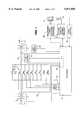
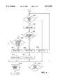
- FIG. 1is a circuit diagram illustrating the principles of an anti-theft device arranged inside a battery
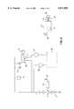
- FIG. 2is a schematic picture of some essential parts of the electrical system of a motor vehicle and a hand-held transmitter
- FIG. 3is a view from above of metal plates to which switches are mounted/connected
- FIG. 4is a sectional view along the line IV--IV in FIG. 3,
- FIG. 5is an exploded perspective view of another embodiment of the metal plates of FIG. 3,
- FIG. 6is a perspective view of the plates of FIG. 5 mounted at each other and with attached switches,
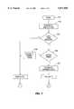
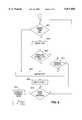
- FIGS. 7-9are flow diagrams of operational steps executed by a processor used in an anti-theft device
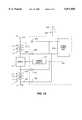
- FIG. 10is an electrical circuit diagram illustrating the power supply to control circuits of the anti-theft device.
- FIG. 1is a circuit diagram of an anti-theft device for a battery which in the preferred case is a starter battery for a, motor driven vehicle or another motor driven vessel or device but it may also be e.g. a stationary battery.
- the batterycontains in the case shown six cells indicated symbolically at 1 which are all connected in series.
- a voltage of +12 Vis obtained between the negative exterior or outermost terminal 3, which conventionally is coupled to ground or the chassis/body of the vehicle, and the positive negative exterior or outermost terminal 5 a voltage of +12 V is obtained.
- the cellsare grouped in or divided into two groups, a lower group 7 including three cells, of which the outermost cell has its negative terminal identical to the exterior negative terminal of the entire battery, and a higher group 9 also including three cells, of which the outermost cell has its positive terminal identical to the positive terminal of the battery.
- a number of semiconductor switches 11, in the case illustrated 8 switches,are connected but also only one switch can be used in the case where it alone can stand the high discharge currents.
- Theycan be transistors of MOSFET-type and they are all connected in parallel having their emitter or source terminal connected to a cell in the higher cell group 9 and their collector or drain terminal connected to a cell in the lower group 7.
- the semiconductor switches 11have their gates connected two and two to each other and these are connected to driver circuits 13 which in turn are controlled by signals from a processor 15.
- the semiconductor switches 11are connected so that for a nonexistent signal from the processor 15, e.g. when it does not obtain any current supply, they are in a blocking state. Thereby no current can be drawn from the battery e.g. in the case where some malfunction exists in the electronic control circuits or in the case where they do not obtain any operating voltage.
- Such a behaviouris simple to achieve, since semiconductor switches for entering a conductive state needs some voltage on or current to their gates.
- the processor 15also contains an A/D-converter 19 for receiving signals, which are evaluated by calculating circuits of the processor for a control of the semiconductor switches through the signals provided to the driver circuits 13.
- a small resistor R 1may be connected in series between two cells, e.g. as is illustrated in FIG. 1 between the semiconductor switches 11 and the lowest cell in the higher group 9 of cells. Electrical leads on both sides of the resistor R 1 can then pass to the A/D-unit 19.
- the resistor R 1consumes electrical power besides the electrical power developed by the switches 11 when they are in a conducting state. Therefore, it is more advantageous to omit the resistor R 1 and instead use the inner resistance of the switches 11 in the conducting state thereof for measuring the current through the battery.
- this resistanceis constant and/or has a well-known behaviour, for example having a well-known temperature dependence, and this resistance can be determined e.g. at the actual connection procedure of the processor to the battery.
- one lead on one side of the resistor R 1is omitted and is replaced with a lead 20 from the opposite electrode of the semiconductor switches 11, so that leads extend to the A/D-unit 19 of the processor 15 from both sides of the switches 11.
- a first temperature sensor 21is placed in the vicinity of the semiconductor switches 11 and provides a signal to the A/D-unit 19 of the processor 15.
- a similar temperature sensor 23is placed at a larger distance from the semiconductor switches 11 but still inside the battery for providing a signal to the processor 15, which represents the temperature of the battery.
- lines or leadsare provided from the exterior terminals 3 and 5 of the battery to the A/D-converter 19 enabling a measurement of the battery voltage.
- One or more zener diodes 24, in the case shown two diodes,are connected in parallel to each other and to the semiconductor switches 11. They are connected with their positive electrode to that side of the semiconductor switches 11 which faces the positive terminal 5 of the battery. They have a zener voltage adapted for protecting the semiconductor switches 11. Thereby no current will pass through the diodes 24 at normal use but they will become conducting when the battery is charged and also for overvoltages over the semiconductor switches, which can occur when the switches 11 are in a conductive or blocking state and can then damage the semiconductor switches 11.
- the processor 15 and other circuits which require a current supply for their operationobtain their energy from e.g. some suitable small separate dry cell battery, not shown, or from the battery itself such as from its exterior terminals 3 and 5 connected to a current supply unit as will be described with reference to FIG. 10.
- the processor 15can be of low power type having special current saving functions, which sets the processor in a low-power mode when no activity exists or no changes exist in the signals delivered to the processor 15.
- the processor 15is further coupled to some device for wireless information communication, in the preferred case a receiver 25 for radio frequency, which possibly can be combined with a transmitter unit.
- a receiver 25 for radio frequencywhich possibly can be combined with a transmitter unit.
- the receiver and also possibly transmitter 25is connected to an antenna indicated at 27.
- the transponder station 29is provided with a specially constructed antenna 31 comprising several winding turns and operating as a winding in a transformer. The second winding of this transformer, not shown, is located in the transponder which is normally carried by the owner or the driver of the vehicle where the battery is placed. When the antenna winding 31 is activated for transmitting high frequency pulses of e.g.
- a voltageis induced in the transponder winding which voltage causes a current therein, whereby the high frequency energy in the received pulses can be stored in a capacitor in the transponder, which is then used for powering electronic circuits in the transponder.
- pulse bursts of various length issued from the antenna winding of the transponder informationcan be transferred to the transponder station 29 which decodes the received pulse bursts and then communicates the retrieved information to the processor 15.
- the transponder station 29can also be used for transmitting information to the transponder.
- the processor 15can also be designed for communication through electrically conducting wires, e.g. for communication with a charging generator for the battery and therefor a serial interface 33 of a conventional kind can be connected to the processor 15.
- FIG. 2is a diagram illustrating how the battery including the cells 1 can be arranged in a motor vehicle, not shown, which is driven by an internal combustion engine 35. From the plus terminal 5 of the battery leads pass to a starter motor 37, a generator 39 and other electrically powered devices such as a clock 41, illumination 43, etc. The line to the starter motor 37 is interrupted by a key switch 45 which is normally open but is closed when turning a key 47, whereby current is supplied to the starter motor 37. The key switch 45 can also close an electrical circuit to the ignition system.
- the semiconductor switches 11are here shown in the shape of a single block and they are controlled by the control circuits 49 which include the electronic components illustrated in FIG. 1 except the semiconductor switches 11.
- the antenna 27is here shown as connected to the control circuits 49 which also include the rf-receiver 25.
- a hand-held transmitter 51comprises transmitter circuits, not shown, a switch 53 which is closed by depressing an operating button or key 55, a small electro-chemical battery indicated at 57, e.g. a lithium battery, and an antenna 59.
- a small electro-chemical battery indicated at 57e.g. a lithium battery
- an antenna 59When the key 55 is depressed, electromagnetic radio waves are emitted from the antenna which contain identifying information coded in a suitable manner. These radio waves are received through the antenna 27 by the control circuits 49, more particularly the receiver/transmitter 25, and they communicate the received information to the processor 15. It compares the information received with information permanently stored in the processor for determining whether the received information is identification information of that hand-held transmitter 51 which is associated with the installation. When there is an agreement the processor 15 provides such signals to the driver circuits 13 and thereby to the semiconductor switches that they allow that a large or high discharge current is drawn from the battery.
- FIGS. 3 and 4illustrate the physical arrangement of the semiconductor switches in the battery.
- Pole pieces 61are connected to the positive and negative terminals of two adjoining cells and they have upper, flat surfaces located in the same plane. From these flat surface threaded bolts 63 protrude upwards and their lower portions are moulded in the pole pieces 61.
- a nut 65 on one bolt 63both a cooling flange 67 and a mounting plate 69 for the semiconductor switches 11 are attached to one pole piece 61, suitably that pole piece which has a lower potential than the other one, so that the bottom surface of the cooling flange 67 directly rests against the top surface of the pole piece.
- the cooling flange 67consists of an elongated rectangular copper plate which is bent to a U-shape having an upper leg projecting above a lower leg.
- two holes 71are provided, one of which is used and a bolt 63 passes therethrough for attaching the cooling flange 67 directly to the upper surface of the pole piece 67 with the exterior, bottom surface of its shorter leg. It will provide a good thermal transfer and a good electrical conduction between the pole piece 61 and the cooling flange 67.
- the other hole 71can be used for other mounting positions of the flange.
- the mounting plate 69is located partly on top of the lower leg of the cooling flange so that the plate is located between the legs. It has also holes 73 corresponding to the holes 71 of the cooling flange 67, through one of which the same bolt 63 passes, the other hole being used for other mounting positions.
- the plate 69has a generally rectangular shape and is like the cooling flange 67 made of a well thermal conducting and electrically conducting material such as copper. By the fact that it partly and over the large part of its bottom side is in a direct contact with the cooling flange 67 also the thermal transfer and the electrical conduction therebetween is good and also to the respective pole piece 67.
- the other pole piece 61which advantageously has a positive polarity, is in the same way, by means of a bolt 63 moulded therein and a nut 75, attached to a bent part 77, which is also made of a conducting material such as aluminium or copper and is in a well conducting contact with the top surface of the pole piece 61.
- a bolt 63 moulded therein and a nut 75attached to a bent part 77, which is also made of a conducting material such as aluminium or copper and is in a well conducting contact with the top surface of the pole piece 61.
- the bolt 63has two holes 79 corresponding to the holes 71 and 73 of the cooling flange 67 and the mounting plate 69 respectively, one hole used for the actual attachment of the part and the other one allowing a different mounting position.
- the bent part 77has generally an exterior rectangular outline but has a deep recess centrally in one of its short sides so that it has a U-shape as seen from above.
- the legsare bent in their area where they connect to the lower part of the U, so that the legs are located at a higher level than the lower portion of the U.
- the elevated portionsare located on top of the mounting plate 69, above areas at the two long sides thereof.
- two holes 81are provided, through which threaded screws 83 pass to be mounted in threaded regions in holes 85 placed in corresponding positions in the mounting plate 69.
- the screws 83are made of an isolating material, e.g.
- the semiconductor switches 11, in the case more than one is needed,are attached in two parallel rows and thus along two parallel lines centrally on the mounting plate 69, parallel to its long sides and adjacent the inner edges of the elevated leg portions of the bent part 77, in the embodiment shown eight semiconductor switches being provided divided into two equally large groups, where thus each group comprises four components. At their bottom sides they are electrically connected to the mounting plate 67 by soldering or similar methods and they have also one of their switching terminals located at their bottom sides. The other switching terminals are located in areas on the top side of the components 11, from which electrically conducting wires 89 extend to regions on the elevated portions of the bent part 77. The wires 89 can be attached by means of bonding methods common for exterior electrical connection of electronic integrated circuit chips.
- the gate terminals of the switches 11are also located at the top sides thereof and therefrom electrically conducting wires 91 extend to electrically conducting areas 93 on the mounting plate 69.
- These electrically conducting areas 93can be conducting layers attached to an isolating substrate, which is in turn bound to the top side of the mounting plate 69, and they are arranged in one row centrally on the mounting plate 69 and there are thus such four such areas.
- Each electrically conducting terminal area 93is located centrally between two semiconductor switches 11 and from such switches that are located opposite each other the wires 91 then extend to the same connection area 93.
- connection area 93From each connection area 93 further electrical connecting wires, not shown, extend to the driver circuits 13 illustrated in FIG. 1.
- the diodes 24are connected in an analogous way as the semiconductor switches 11 and are thus mounted with their bottom sides attached in an electrically conducting way to the top surface of the mounting plate 69 at the end edges of the elevated leg portions of the bent part 77.
- One of the electrodes of the diodes 24is located on the bottom sides thereof, the other electrodes being located on the top sides thereof, where electrically conducting wires 95 connect them to areas on the elevated leg portions of the bent part 77, which are located at the ends of the leg portions.
- the temperature sensor 21 for monitoring the semiconductor switches 11is also attached to the mounting plate 69, e.g. next to the row of the centrally located electrical connecting areas 93.
- the sensor 21is connected to the processor 19, see FIG. 1, through a connection wire, not shown.
- holes 97are provided in the top leg of the cooling flange 67.
- FIG. 5An alternative embodiment of the mounting plates to which the semiconductor switches 11 are attached/connected is illustrated by the exploded perspective view of FIG. 5 and in a state mounted to each other by the perspective view of FIG. 6.
- the rectangular mounting plate 69 on which the semiconductor switches 11 are mounted in the embodiment according to FIG. 3 and 4is flat as above but is here replaced with a plate 69' which certainly has the same general exterior outline but which at its short side facing the other plate has a long or deep recess 101, so that it will have a U-shape.
- the other plate 77'has, differing from the plate or the bent part 77 in the first embodiment, no bent region but is essentially completely flat.
- the plates 69', 77'have thus complementary profiles as seen from above, so that they when they are placed at each other provide a plate having a substantially rectangular shape, see FIG. 6.
- a gap or interspaceBetween the sides in the recess 101 and the sides of the leg 103 of the T there is a gap or interspace, so that the plates are electrically isolated from each other.
- This interspaceis filled by side portions of a distance sleeve 105 made of an isolating material, such as of a suitable plastics or ceramics material.
- the sleeve 105has a generally rectangular cross-section and a longitudinal hole 107 passes therethrough receiving the leg 103 of the second mounting plate 77' and it has, on the sides of the hole 107, grooves 109 for receiving the inner edges of the first mounting plate 69', those edges which are located at the recess 101.
- On the top sidethe sleeve 105 has rectangular holes 111 close to the longitudinal hole 109.
- first mounting plate 69'On the top surface of the first mounting plate 69' also surface coatings are deposited within different surface areas. Thus there are several rectangular areas, e.g. square, areas 113 at the marginal region next to the recess 101 of tin solder for attachment and connection of the semiconductor switches 11. In the embodiment shown there are five such areas adjacent each side of the recess. Further there are elongated areas or connection rims 115 in the neighbourhood of the rectangular tin solder areas 113 and adjacent the exterior long sides of the first mounting plate 77' and these areas 115 can be of thick film type comprising several layers, the bottom layers of which are adhesive and electrically isolating and the top layers can be electrically conducting or form different electrically conducting current paths.
- the semiconductor switches 11can be soldered to the first mounting plate 69' before mounting to the second mounting plate 77'. After the assembly of these parts to each other then the further electrical terminals of the semiconductor switches 11 are connected through wires 89' from the terminals of the switches located on the top surface thereof through the holes 111 in the top side of the sleeve part 105 into and up to the free surface located therein of the second mounting plate 77'. It can, for permitting wire bonding by means of ultra sound of the kind used for connecting integrated circuit plates, be of aluminium.
- the gate electrodes of the semiconductor switches 11are connected by means of wires 91' from the top side of the switches 11 to suitable areas on the connection rims 115.
- connection rims 115are then modified in the corresponding way so that connection wires can be connected to isolated portions of their top surface.
- the mounting plates 69' and 77'comprise mounting holes 73 and 79 respectively in the same way as the mounting plate 69' and the bent part 77 in the first embodiment and can by means of bolts extending through the holes directly be attached to pole pieces of a battery.
- a cooling plate or cooling flange 67can be placed below the plate 77', to which the main portion of the switch element 11 is attached.
- the bottom surfaces of the plates 69' and 77', which are mounted to each other,will extend in the same one plane, and therefore an insert or intermediate part having the same thickness of material as the cooling fin 69 and of a well electrically and thermally conducting material must be placed under the second mounting plate 77'.
- An alternativeis moulding the pole pieces 61, see FIG. 4, to give them different heights.
- FIGS. 7-9are flow diagrams illustrating the various steps which are executed by the processor 15. These flow diagrams are executed, first that of FIG. 7 and then one of the flow diagrams of FIGS. 8 and 9.
- the processor 15can naturally also be programmed to perform the control of the semiconductor switches 11 so that they are always either in a conducting state or a blocking state and a toggling of the state is made at the reception of a correct identifying signal from the outside.
- a control procedureis preferred which allows that normally a low current is drawn from the battery, also without receiving a correct identifying signal.
- the stateis changed between this state having a low allowed current and a larger current which is sufficient for e.g. driving an electrical starter motor.
- the procedural steps of the flow diagram of the main routinestart in FIG. 7 in a start block 701, after which in a block 702 the system is transferred to a locked state, where only small discharge currents are allowed from the battery. Then it is determined in a block 703, whether a correct identifying code has been received. If it is decided that a correct code has been received, it is determined in a block 705, whether the system, i.e. the processor, is in a locked state or not.
- a locked statemeans here that the anti-theft function is started and that a start of the starter motor cannot be done, since only low discharge currents can be drawn. If the processor is earlier set to a locked state, it is transferred to an open state in a block 707 and the routine of FIG.
- a block 801it is first decided in a block 801, whether the temperature of the switches 11 is too high. It is decided by comparing the signal which arrives from the temperature sensor 21 and which has been converted to digital form to a threshold value.
- the temperature of the battery itselfcan be tested by comparing the signal from the temperature sensor 23 to some suitable threshold value.
- the switches 11are allowed to continue to remain in a conductive state or "on-state", which is illustrated by a block 803, after which it is decided in a block 805, whether the current through the battery is larger than a predetermined, rather low value, in a practical example a value equal to 6 A, that is normally a few Amperes, and possible currents exceeding this value have a short duration of time, i.e. last at most a predetermined time, say 10 ms, that is generally a small fraction of a second. If it is the case, a non-permitted high current is drawn during a sufficiently long time for excluding occasional current surges, and probably a try is made to start the vehicle or that some malfunction, e.g.
- a short-circuitexists in the electrical system in the vehicle, and then in a block 807 the switches are set to a closed state or "off-state", so that no current at all can be drawn from the battery.
- This statecomprising open or blocking switches 11 is allowed to continue during a predetermined rather long time period, as is illustrated by a block 809, say for example ten or generally a few seconds.
- a block 810it is asked in a block 810, whether a correct identifying signal has been received during the time since it was latest checked. If no correct code has been received, the whole routine of FIG. 8 is performed again starting in the block 801.
- the systemis transferred to its other state, the open state in a block 812, after which the routine of FIG. 9 is executed. If it was decided in the block 805, that only currents below the threshold value are drawn, it is decided in the block 811, whether a state exists where the capacity of the battery is low and where it is not at all allowed to draw any extra current. In order to arrive at this state the processor has decided earlier, by checking the output voltage and the output current of the battery and considering the temperature of the battery by means of the signal from the temperature sensor 23, that the battery capacity is so low that it is only sufficient for starting the motor.
- the capacity of the batterycan be estimated in a known way, e.g.
- a block 901it is decided, like in the block 801, whether the temperature of the switches 11 is too high and possibly also, whether the temperature of the whole battery is not too high. If it is not true, the switches 11 are allowed to continue to be in a conductive state or "on-state", as is illustrated by a block 903, and now a start of a vehicle motor by means of an electrically driven starter motor can be done with a large current drawn. However, for avoiding the risk of short-circuits and that extremely high currents are drawn, it is checked in a block 905, whether the current drawn exceeds a large predetermined value, e.g.
- FIG. 9exceeds 1200 A, that is a value well above that needed normally by the starter motor, e.g. equal to a value of a few times the needed current, and that this is true during a sufficiently long time, say during at least 1 ms, that is during at least a time period of small fraction of a second.
- the current drawn nowexceeds the maximum current which is allowed for the starter motor, say as is illustrated in the FIG. 9 exceeds 300 A and whether it is true during a long time period, say a time of at least 10 s, that is a rather long time of several seconds.
- the systemis transferred to a locked state in a block 916, after which the routine of FIG. 8 is performed. If it was decided in the block 909 that a high starting current is drawn during a too long time, there is possibly some malfunction in the starter motor or in any case it can be overheated, so that the switches 11 are brought to a non-conducting state in a block 911 and this state wherein the battery is switched off is then allowed to continue during a rather long time, say during 10 s, that is during a time period of several seconds, as is illustrated by a block 913, after which the block 914 is performed as above.
- the procedurecontinues to switching off again currents drawn from the battery and that this is allowed to be true during a predetermined, rather long time period, say 3 s or generally a time period of a few seconds which can be shorter, however, than the delay time when only there is an overcurrent drawn by the battery in the block 913, as is illustrated by the blocks 915 and 917.
- the block 914is executed as above. If it was decided in the block 901, that the temperature of the switches is too high, the battery is switched off again and the switches are set to a non-conducting state, as is illustrated by a block 919, after which the block 914 is performed as above.
- FIG. 10is a schematic circuit diagram of an anti-theft battery.
- itis a lead-acid battery having six battery cells 1 connected in series.
- the voltage provided by the battery between the exterior or outermost terminals 3 and 5 thereofis then nominally 12 V.
- the electronic circuits for controlling the switches 11comprise the processor 15, drivers 13, rf-receiver/transmitter and interfaces, here all included in an electronics circuit block 117.
- a controlled poweris required, e.g. for supplying a voltage of 5 V.
- a power supply unit 119is arranged which at its output terminals provides a controlled direct voltage.
- the power supply unit 119receives the energy necessary for the operation thereof normally from the exterior terminals 3 and 5 of the battery through leads 121, 121'.
- the power supply unitcan also obtain a reduced voltage through leads 123, 123' extending from the negative and positive terminals of the switches 11.
- the leads 121, 121' to the exterior battery terminals 3, 5can be rather long and in addition they may attached by means of screws, so that some risk may exist for the occurrence of an interrupt of the voltage supply from the exterior terminals 3, 5.
- the power supply unit 119is supplied only from three battery cells, i.e. with a voltage of about 6 V.
- the power supply unit 119also obtains a voltage of 6 V but in this case in parallel from two separated groups of each three cells, the three most negative cells 1.1, 1.2, 1.3 and the three most positive cells 1.4, 1.5, 1.6.
- a first diode 125is connected in the line 121 to the negative external terminal 3 and has its negative electrode connected to this terminal 3.
- a diode 127is connected in the fine 121' to the positive external terminal 5 and its positive electrode is connected to this external terminal 5.
- a diode 129is connected, the negative electrode of which is connected to the plus-side of the switches 11 or generally to the negative terminal of the fourth battery cell 1.4.
- a diode 131is connected in the lead 123 to the negative side of the switches 11. This diode 123 has its positive electrode connected to the negative side of the switches 11, or equivalently to the positive terminal of the third battery cell 1.3.
- the power supply unit 119obtains its supply voltage from the three most positive cells of the battery, i.e. the cells 1.4, 1.5 and 1.6.
- An interrupt placewhich is accessible from the outside, is advantageously provided for the power supply of the electronic circuits 117, as is indicated in FIG. 10 by two contact tongues 133, which are connected in a power supply line at a location very near the power supply unit 119.
- the contact tongues 133can, when the battery is to be used, be closed by means of a suitably constructed contact metal strap or jumper, indicated at 135.
Landscapes
- Engineering & Computer Science (AREA)
- Chemical & Material Sciences (AREA)
- Chemical Kinetics & Catalysis (AREA)
- Electrochemistry (AREA)
- General Chemical & Material Sciences (AREA)
- Manufacturing & Machinery (AREA)
- Mechanical Engineering (AREA)
- Microelectronics & Electronic Packaging (AREA)
- Power Engineering (AREA)
- Physics & Mathematics (AREA)
- General Physics & Mathematics (AREA)
- Secondary Cells (AREA)
- Battery Mounting, Suspending (AREA)
- Charge And Discharge Circuits For Batteries Or The Like (AREA)
Abstract
Description
Claims (26)
Applications Claiming Priority (5)
| Application Number | Priority Date | Filing Date | Title |
|---|---|---|---|
| SE9402216ASE511032C2 (en) | 1994-06-22 | 1994-06-22 | Connection of control circuit for battery with theft protection |
| SE9402217 | 1994-06-22 | ||
| SE9402216 | 1994-06-22 | ||
| SE9402217ASE504848C2 (en) | 1994-06-22 | 1994-06-22 | Anti-theft switch device for motor vehicle battery |
| PCT/SE1995/000767WO1995035228A1 (en) | 1994-06-22 | 1995-06-21 | Anti-theft battery |
Publications (1)
| Publication Number | Publication Date |
|---|---|
| US5871858Atrue US5871858A (en) | 1999-02-16 |
Family
ID=26662083
Family Applications (1)
| Application Number | Title | Priority Date | Filing Date |
|---|---|---|---|
| US08/765,238Expired - Fee RelatedUS5871858A (en) | 1994-06-22 | 1995-06-21 | Anti-theft battery |
Country Status (6)
| Country | Link |
|---|---|
| US (1) | US5871858A (en) |
| EP (2) | EP0765256B1 (en) |
| AU (1) | AU2812895A (en) |
| DE (1) | DE69522804T2 (en) |
| ES (1) | ES2164155T3 (en) |
| WO (1) | WO1995035228A1 (en) |
Cited By (103)
| Publication number | Priority date | Publication date | Assignee | Title |
|---|---|---|---|---|
| US6063523A (en)* | 1999-04-16 | 2000-05-16 | Quallion, Llc | Battery tab attachment method and apparatus |
| US6173350B1 (en)* | 1997-10-17 | 2001-01-09 | Eveready Battery Company Inc. | System and method for writing data to a serial bus from a smart battery |
| WO2001018391A1 (en) | 1999-09-10 | 2001-03-15 | Intra International Ab | System and method for protecting a cranking subsystem |
| US6377031B1 (en) | 1999-09-10 | 2002-04-23 | Intra International Ab | Intelligent switch for power management |
| US20020080546A1 (en)* | 2000-11-03 | 2002-06-27 | Peter Zdziech | Automatic battery disconnect system |
| US6465908B1 (en) | 1999-09-10 | 2002-10-15 | Intra International Ab | Intelligent power management system |
| US20030064257A1 (en)* | 2001-10-02 | 2003-04-03 | Norikazu Iwasaki | Secondary batteries having a protective circuit |
| US20030155930A1 (en)* | 2000-04-25 | 2003-08-21 | Jes Thomsen | Current measuring circuit suited for batteries |
| US6635974B1 (en) | 1999-09-10 | 2003-10-21 | Midtronics, Inc. | Self-learning power management system and method |
| US6744149B1 (en) | 1999-09-10 | 2004-06-01 | Midtronics, Inc. | System and method for providing step-down power conversion using an intelligent switch |
| US20040113494A1 (en)* | 2000-09-01 | 2004-06-17 | Karuppana Samy V. | Daytime running light control using an intelligent power management system |
| US6807041B2 (en)* | 2000-08-23 | 2004-10-19 | Beru Ag | Electronic triggering for heating elements |
| US20050024061A1 (en)* | 1997-11-03 | 2005-02-03 | Michael Cox | Energy management system for automotive vehicle |
| US20050057256A1 (en)* | 2000-03-27 | 2005-03-17 | Midtronics, Inc. | Scan tool for electronic battery tester |
| US20050093371A1 (en)* | 2000-11-03 | 2005-05-05 | Zdziech Peter M. | Automatic battery disconnect system |
| US20050162172A1 (en)* | 1997-11-03 | 2005-07-28 | Midtronics, Inc. | Wireless battery monitor |
| US20050212521A1 (en)* | 2000-03-27 | 2005-09-29 | Midtronics, Inc. | Electronic battery tester or charger with databus connection |
| US20060217914A1 (en)* | 2000-03-27 | 2006-09-28 | Bertness Kevin I | Battery testers with secondary functionality |
| US20060282227A1 (en)* | 1997-11-03 | 2006-12-14 | Bertness Kevin I | Electronic battery tester with network communication |
| US20070018651A1 (en)* | 2004-07-22 | 2007-01-25 | Bertness Kevin I | Broad-band low-inductance cables for making Kelvin connections to electrochemical cells and batteries |
| US20070069734A1 (en)* | 1997-11-03 | 2007-03-29 | Bertness Kevin I | Automotive vehicle electrical system diagnostic device |
| US20070159177A1 (en)* | 1997-11-03 | 2007-07-12 | Midtronics, Inc. | Automotive vehicle electrical system diagnostic device |
| US20070194793A1 (en)* | 2003-09-05 | 2007-08-23 | Bertness Kevin I | Method and apparatus for measuring a parameter of a vehicle electrical system |
| US20070244660A1 (en)* | 1996-07-29 | 2007-10-18 | Bertness Kevin I | Alternator tester |
| US20080043752A1 (en)* | 2006-08-18 | 2008-02-21 | Mohrmann Iii Leonard E | System and Method for Clock Domain Management |
| US20080079389A1 (en)* | 2006-09-29 | 2008-04-03 | International Truck Intellectual Property Company, Llc | Motor vehicle battery disconnect circuit having electronic disconnects |
| DE112006002329T5 (en) | 2005-08-29 | 2008-07-10 | Midtronics, Inc., Willowbrook | Diagnostic device for electrical installations of motor vehicles |
| US20080204030A1 (en)* | 2007-02-27 | 2008-08-28 | Midtronics, Inc. | Battery tester with promotion feature |
| US20090024266A1 (en)* | 2007-07-17 | 2009-01-22 | Bertness Kevin I | Battery tester for electric vehicle |
| US20090051365A1 (en)* | 2003-09-05 | 2009-02-26 | Bertness Kevin I | Method and apparatus for measuring a parameter of a vehicle electrical system |
| US7557586B1 (en) | 1999-11-01 | 2009-07-07 | Midtronics, Inc. | Electronic battery tester |
| US20090184165A1 (en)* | 2004-08-20 | 2009-07-23 | Midtronics, Inc. | Integrated tag reader and environment sensor |
| US20090187495A1 (en)* | 2004-08-20 | 2009-07-23 | Midtronics, Inc. | Simplification of inventory management |
| US20090212781A1 (en)* | 2004-08-20 | 2009-08-27 | Midtronics, Inc. | System for automatically gathering battery information |
| US20090295395A1 (en)* | 2007-12-06 | 2009-12-03 | Bertness Kevin I | Storage battery and battery tester |
| US20090311919A1 (en)* | 2008-06-16 | 2009-12-17 | Midtronics, Inc. | Clamp for Electrically Coupling to a Battery Contact |
| US7710119B2 (en) | 2004-12-09 | 2010-05-04 | Midtronics, Inc. | Battery tester that calculates its own reference values |
| US7772850B2 (en) | 2004-07-12 | 2010-08-10 | Midtronics, Inc. | Wireless battery tester with information encryption means |
| US7777612B2 (en) | 2004-04-13 | 2010-08-17 | Midtronics, Inc. | Theft prevention device for automotive vehicle service centers |
| US7808375B2 (en) | 2007-04-16 | 2010-10-05 | Midtronics, Inc. | Battery run down indicator |
| US20110015815A1 (en)* | 2007-07-17 | 2011-01-20 | Bertness Kevin I | Battery tester for electric vehicle |
| US7977914B2 (en) | 2003-10-08 | 2011-07-12 | Midtronics, Inc. | Battery maintenance tool with probe light |
| US7999505B2 (en) | 1997-11-03 | 2011-08-16 | Midtronics, Inc. | In-vehicle battery monitor |
| US20110208451A1 (en)* | 2010-02-25 | 2011-08-25 | Champlin Keith S | Method and apparatus for detecting cell deterioration in an electrochemical cell or battery |
| WO2011159455A1 (en) | 2010-06-18 | 2011-12-22 | Midtronics, Inc. | Battery maintenance device with thermal buffer |
| US8198900B2 (en) | 1996-07-29 | 2012-06-12 | Midtronics, Inc. | Automotive battery charging system tester |
| US20130113455A1 (en)* | 2011-11-03 | 2013-05-09 | Chin-Tsung Lin | Power supply management apparatus and burglarproof power supply system that uses the power supply management apparatus |
| US20130125850A1 (en)* | 2011-11-17 | 2013-05-23 | Ford Global Technologies, Llc | Starter motor control with pre-spin |
| US8513949B2 (en) | 2000-03-27 | 2013-08-20 | Midtronics, Inc. | Electronic battery tester or charger with databus connection |
| US8564245B2 (en) | 2009-02-06 | 2013-10-22 | Robert Bosch Gmbh | Traction battery having increased reliability |
| US8738309B2 (en) | 2010-09-30 | 2014-05-27 | Midtronics, Inc. | Battery pack maintenance for electric vehicles |
| US8872517B2 (en) | 1996-07-29 | 2014-10-28 | Midtronics, Inc. | Electronic battery tester with battery age input |
| US8958998B2 (en) | 1997-11-03 | 2015-02-17 | Midtronics, Inc. | Electronic battery tester with network communication |
| US9018958B2 (en) | 2003-09-05 | 2015-04-28 | Midtronics, Inc. | Method and apparatus for measuring a parameter of a vehicle electrical system |
| WO2015089249A1 (en) | 2013-12-12 | 2015-06-18 | Midtronics, Inc. | Battery tester and battery registration tool |
| EP2897229A1 (en) | 2014-01-16 | 2015-07-22 | Midtronics, Inc. | Battery clamp with endoskeleton design |
| US20150244167A1 (en)* | 2014-02-24 | 2015-08-27 | Delta Electronics, Inc. | Output power protection apparatus and method of operating the same |
| US9201120B2 (en) | 2010-08-12 | 2015-12-01 | Midtronics, Inc. | Electronic battery tester for testing storage battery |
| US9229062B2 (en) | 2010-05-27 | 2016-01-05 | Midtronics, Inc. | Electronic storage battery diagnostic system |
| US9244100B2 (en) | 2013-03-15 | 2016-01-26 | Midtronics, Inc. | Current clamp with jaw closure detection |
| US9255955B2 (en) | 2003-09-05 | 2016-02-09 | Midtronics, Inc. | Method and apparatus for measuring a parameter of a vehicle electrical system |
| US20160090000A1 (en)* | 2014-09-30 | 2016-03-31 | Ford Global Technologies, Llc | Method for charging the starter battery of a vehicle |
| US9312575B2 (en) | 2013-05-16 | 2016-04-12 | Midtronics, Inc. | Battery testing system and method |
| US9403442B2 (en) | 2011-11-10 | 2016-08-02 | Alcatel Lucent | Technique for discharging an energy storage of a vehicle |
| WO2016123075A1 (en) | 2015-01-26 | 2016-08-04 | Midtronics, Inc. | Alternator tester |
| US9425487B2 (en) | 2010-03-03 | 2016-08-23 | Midtronics, Inc. | Monitor for front terminal batteries |
| WO2016176405A1 (en) | 2015-04-29 | 2016-11-03 | Midtronics, Inc. | Calibration and programming of in-vehicle battery sensors |
| US9496720B2 (en) | 2004-08-20 | 2016-11-15 | Midtronics, Inc. | System for automatically gathering battery information |
| US9537332B2 (en) | 2013-05-30 | 2017-01-03 | Canara, Inc. | Apparatus, system and method for charge balancing of individual batteries in a string of batteries using battery voltage and temperature, and detecting and preventing thermal runaway |
| CN107508372A (en)* | 2017-08-24 | 2017-12-22 | 苏州麦喆思科电子有限公司 | A kind of high filtering type dry cell intelligently switches electric supply installation |
| US9851411B2 (en) | 2012-06-28 | 2017-12-26 | Keith S. Champlin | Suppressing HF cable oscillations during dynamic measurements of cells and batteries |
| US9966676B2 (en) | 2015-09-28 | 2018-05-08 | Midtronics, Inc. | Kelvin connector adapter for storage battery |
| US10033213B2 (en)* | 2014-09-30 | 2018-07-24 | Johnson Controls Technology Company | Short circuit wake-up system and method for automotive battery while in key-off position |
| US10046649B2 (en) | 2012-06-28 | 2018-08-14 | Midtronics, Inc. | Hybrid and electric vehicle battery pack maintenance device |
| US10120034B2 (en) | 2015-10-07 | 2018-11-06 | Canara, Inc. | Battery string monitoring system |
| US10222397B2 (en) | 2014-09-26 | 2019-03-05 | Midtronics, Inc. | Cable connector for electronic battery tester |
| US10249406B2 (en)* | 2016-10-13 | 2019-04-02 | Robert Bosch Gmbh | Cable harness |
| WO2019147546A1 (en) | 2018-01-23 | 2019-08-01 | Midtronics, Inc. | High capacity battery balancer |
| WO2019147549A1 (en) | 2018-01-23 | 2019-08-01 | Midtronics, Inc. | Hybrid and electric vehicle battery maintenance device |
| US10429449B2 (en) | 2011-11-10 | 2019-10-01 | Midtronics, Inc. | Battery pack tester |
| US10473555B2 (en) | 2014-07-14 | 2019-11-12 | Midtronics, Inc. | Automotive maintenance system |
| US10608353B2 (en) | 2016-06-28 | 2020-03-31 | Midtronics, Inc. | Battery clamp |
| CN111180808A (en)* | 2018-11-13 | 2020-05-19 | 罗伯特·博世有限公司 | Battery pack system for use on the onboard power supply system of a motor vehicle |
| US10843574B2 (en) | 2013-12-12 | 2020-11-24 | Midtronics, Inc. | Calibration and programming of in-vehicle battery sensors |
| WO2021092109A1 (en) | 2019-11-05 | 2021-05-14 | Midtronics, Inc. | System for charging a series of connected batteries |
| US11054480B2 (en) | 2016-10-25 | 2021-07-06 | Midtronics, Inc. | Electrical load for electronic battery tester and electronic battery tester including such electrical load |
| US11081814B2 (en)* | 2016-10-31 | 2021-08-03 | Autonetworks Technologies, Ltd. | Wiring module |
| US11325479B2 (en) | 2012-06-28 | 2022-05-10 | Midtronics, Inc. | Hybrid and electric vehicle battery maintenance device |
| US11474153B2 (en) | 2019-11-12 | 2022-10-18 | Midtronics, Inc. | Battery pack maintenance system |
| US11486930B2 (en) | 2020-01-23 | 2022-11-01 | Midtronics, Inc. | Electronic battery tester with battery clamp storage holsters |
| US11513160B2 (en) | 2018-11-29 | 2022-11-29 | Midtronics, Inc. | Vehicle battery maintenance device |
| US11566972B2 (en) | 2019-07-31 | 2023-01-31 | Midtronics, Inc. | Tire tread gauge using visual indicator |
| US11650259B2 (en) | 2010-06-03 | 2023-05-16 | Midtronics, Inc. | Battery pack maintenance for electric vehicle |
| US11668779B2 (en) | 2019-11-11 | 2023-06-06 | Midtronics, Inc. | Hybrid and electric vehicle battery pack maintenance device |
| US11740294B2 (en) | 2010-06-03 | 2023-08-29 | Midtronics, Inc. | High use battery pack maintenance |
| US11973202B2 (en) | 2019-12-31 | 2024-04-30 | Midtronics, Inc. | Intelligent module interface for battery maintenance device |
| WO2024258934A1 (en) | 2023-06-13 | 2024-12-19 | Midtronics, Inc. | Electric vehicle maintenance device for low voltage electrical system |
| US12237482B2 (en) | 2019-12-31 | 2025-02-25 | Midtronics, Inc. | Intelligent module interface for battery maintenance device |
| WO2025085631A1 (en) | 2023-10-18 | 2025-04-24 | Midtronics, Inc. | Electric vehicle maintenance device abstract of the disclosure |
| WO2025096499A1 (en) | 2023-10-30 | 2025-05-08 | Midtronics, Inc. | Vehicle maintenance system with dynamic network |
| US12320857B2 (en) | 2016-10-25 | 2025-06-03 | Midtronics, Inc. | Electrical load for electronic battery tester and electronic battery tester including such electrical load |
| US12330513B2 (en) | 2022-02-14 | 2025-06-17 | Midtronics, Inc. | Battery maintenance device with high voltage connector |
| US12392833B2 (en) | 2022-05-09 | 2025-08-19 | Midtronics, Inc. | Electronic battery tester |
Families Citing this family (12)
| Publication number | Priority date | Publication date | Assignee | Title |
|---|---|---|---|---|
| GB2319653B (en)* | 1996-11-23 | 1999-08-11 | Peter Phillip Gatehouse | Security battery |
| GB2328785A (en)* | 1997-09-01 | 1999-03-03 | Seumas Alasdair Graeme Ascott | Electrical battery for a vehicle |
| US5977654A (en)* | 1997-09-25 | 1999-11-02 | Johnson Controls Technology Company | Anti-theft System for disabling a vehicle engine that includes a multi-contact switch for disconnecting the battery and loading the vehicle electrical system |
| US5965954A (en)* | 1997-09-25 | 1999-10-12 | Johnson Controls Technology Company | Anti-theft system for disabling a vehicle engine |
| EP1258838A3 (en)* | 2001-05-18 | 2004-09-15 | Markus R. Schneider | Device for current detection and use thereof |
| TWM261911U (en)* | 2004-04-23 | 2005-04-11 | Yung-Hsin Tsao | A mobile power supply apparatus having a control device for controlling power-on and power-off |
| DE102011118716B4 (en)* | 2011-11-16 | 2017-07-20 | Audi Ag | Storage system for electrical energy |
| TWM529618U (en)* | 2016-05-18 | 2016-10-01 | Reduce Carbon Energy Develop Co Ltd | Battery management system for vehicle starting battery |
| DE102020128049B3 (en) | 2020-10-26 | 2021-12-30 | Audi Aktiengesellschaft | Diagnosis of the active discharge of an HV intermediate circuit |
| DE102020128734B4 (en)* | 2020-11-02 | 2024-10-31 | Einhell Germany Ag | restriction on the use of an electrical device |
| TWI751920B (en)* | 2021-03-04 | 2022-01-01 | 宏碁股份有限公司 | Anti-theft method for electric vehicle |
| JP2024102725A (en)* | 2023-01-19 | 2024-07-31 | 株式会社Gsユアサ | Electric storage device, management device, temperature estimation method of electric storage element, and computer program |
Citations (16)
| Publication number | Priority date | Publication date | Assignee | Title |
|---|---|---|---|---|
| US4067041A (en)* | 1975-09-29 | 1978-01-03 | Hutson Jearld L | Semiconductor device package and method of making same |
| EP0090439A2 (en)* | 1982-03-26 | 1983-10-05 | Motorola, Inc. | Electrically isolated semiconductor power device |
| WO1985000234A1 (en)* | 1983-06-24 | 1985-01-17 | Mouse Systems Corporation | Detector for electro-optical mouse |
| US4553127A (en)* | 1983-06-30 | 1985-11-12 | Issa Darrell E | Battery lock anti-theft system |
| EP0161365A2 (en)* | 1983-12-23 | 1985-11-21 | Mr. Gasket Co. | Self-contained anti-theft device for motor vehicles |
| WO1990006632A1 (en)* | 1988-12-07 | 1990-06-14 | British Telecommunications Public Limited Company | Data compression |
| WO1993000009A1 (en)* | 1991-06-26 | 1993-01-07 | Schering Aktiengesellschaft | Pesticidal compositions comprising amitraz and imidacloprid |
| WO1993000225A1 (en)* | 1991-06-28 | 1993-01-07 | Ital Idee S.R.L. | Security information carrier, especially for graphic information |
| WO1993001345A1 (en)* | 1991-07-04 | 1993-01-21 | Onodera Doraikuriiningu Kojo Co., Ltd. | Cartridge filter cleaning apparatus serving also as filtration apparatuses for installed dry cleaning machines |
| GB2263012A (en)* | 1992-01-04 | 1993-07-07 | David John Cuckow | Switch in accumulator battery to prevent unauthorised use |
| US5283463A (en)* | 1992-03-05 | 1994-02-01 | Westinghouse Electric Corp. | High power self commutating semiconductor switch |
| US5419983A (en)* | 1993-07-20 | 1995-05-30 | Matsushita Electric Industrial Co., Ltd. | Lead acid battery |
| US5496654A (en)* | 1994-06-22 | 1996-03-05 | Perkins; Bradley A. | Secondary battery cell interconnection for protection from internal shorts |
| US5552744A (en)* | 1994-08-11 | 1996-09-03 | Ltx Corporation | High speed IDDQ monitor circuit |
| US5569550A (en)* | 1995-02-03 | 1996-10-29 | Motorola, Inc. | Battery pack having under-voltage and over-voltage protection |
| US5652538A (en)* | 1995-02-08 | 1997-07-29 | Bull S.A. | Integrated curcuit with conductance adjustable by digital control signal |
Family Cites Families (16)
| Publication number | Priority date | Publication date | Assignee | Title |
|---|---|---|---|---|
| US4289836A (en) | 1980-03-05 | 1981-09-15 | Lemelson Jerome H | Rechargeable electric battery system |
| US4390841A (en) | 1980-10-14 | 1983-06-28 | Purdue Research Foundation | Monitoring apparatus and method for battery power supply |
| US4553081A (en) | 1982-06-07 | 1985-11-12 | Norand Corporation | Portable battery powered system |
| WO1986007319A1 (en)* | 1983-12-14 | 1986-12-18 | FORSBERG, Torbjörn | Method and means for preventing theft of a powered means of transportation |
| US5184023A (en) | 1983-12-23 | 1993-02-02 | James E. Winner | Self-contained anti-theft device for motor vehicles |
| US4555523A (en) | 1984-06-04 | 1985-11-26 | E. R. Squibb & Sons, Inc. | 7-Oxabicycloheptane substituted thio prostaglandin analogs and their use in the treatment of thrombolytic disease |
| ES279755U (en) | 1984-06-06 | 1985-01-01 | Sociedad Espanola Del Acumulador Tudor S.A. | A storage battery. |
| US4798968A (en) | 1987-05-15 | 1989-01-17 | Deem James R | Battery disconnect apparatus |
| US4965738A (en) | 1988-05-03 | 1990-10-23 | Anton/Bauer, Inc. | Intelligent battery system |
| DE3841769C1 (en)* | 1988-12-12 | 1990-06-07 | Juergen 8014 Neubiberg De Wemhoener | Circuit for ensuring the provision of starting energy in motor vehicles with internal combustion engines |
| US5023591A (en)* | 1989-11-15 | 1991-06-11 | Allen V. Edwards | Anti-theft control apparatus |
| WO1993017481A1 (en)* | 1990-05-16 | 1993-09-02 | Pita Witehira | Automotive power distribution and switching system |
| IT1245436B (en)* | 1991-03-05 | 1994-09-20 | Iveco Fiat | DEVICE FOR CHECKING THE BATTERY CHARGE STATUS, IN PARTICULAR ON BOARD A VEHICLE |
| GB2260635A (en)* | 1991-10-16 | 1993-04-21 | Europ Research Corp | Battery and vehicle protection unit |
| WO1993015935A1 (en)* | 1992-02-07 | 1993-08-19 | Fibre Optic Technologies Limited | Motor vehicle anti-theft system |
| EP0648380B1 (en) | 1992-07-01 | 1996-10-16 | B.I.G. Batteries Limited | Security batteries for automotive vehicles |
- 1995
- 1995-06-21WOPCT/SE1995/000767patent/WO1995035228A1/enactiveIP Right Grant
- 1995-06-21EPEP95923648Apatent/EP0765256B1/ennot_activeExpired - Lifetime
- 1995-06-21EPEP01103067Apatent/EP1149744A3/ennot_activeWithdrawn
- 1995-06-21USUS08/765,238patent/US5871858A/ennot_activeExpired - Fee Related
- 1995-06-21AUAU28128/95Apatent/AU2812895A/ennot_activeAbandoned
- 1995-06-21DEDE69522804Tpatent/DE69522804T2/ennot_activeExpired - Fee Related
- 1995-06-21ESES95923648Tpatent/ES2164155T3/ennot_activeExpired - Lifetime
Patent Citations (16)
| Publication number | Priority date | Publication date | Assignee | Title |
|---|---|---|---|---|
| US4067041A (en)* | 1975-09-29 | 1978-01-03 | Hutson Jearld L | Semiconductor device package and method of making same |
| EP0090439A2 (en)* | 1982-03-26 | 1983-10-05 | Motorola, Inc. | Electrically isolated semiconductor power device |
| WO1985000234A1 (en)* | 1983-06-24 | 1985-01-17 | Mouse Systems Corporation | Detector for electro-optical mouse |
| US4553127A (en)* | 1983-06-30 | 1985-11-12 | Issa Darrell E | Battery lock anti-theft system |
| EP0161365A2 (en)* | 1983-12-23 | 1985-11-21 | Mr. Gasket Co. | Self-contained anti-theft device for motor vehicles |
| WO1990006632A1 (en)* | 1988-12-07 | 1990-06-14 | British Telecommunications Public Limited Company | Data compression |
| WO1993000009A1 (en)* | 1991-06-26 | 1993-01-07 | Schering Aktiengesellschaft | Pesticidal compositions comprising amitraz and imidacloprid |
| WO1993000225A1 (en)* | 1991-06-28 | 1993-01-07 | Ital Idee S.R.L. | Security information carrier, especially for graphic information |
| WO1993001345A1 (en)* | 1991-07-04 | 1993-01-21 | Onodera Doraikuriiningu Kojo Co., Ltd. | Cartridge filter cleaning apparatus serving also as filtration apparatuses for installed dry cleaning machines |
| GB2263012A (en)* | 1992-01-04 | 1993-07-07 | David John Cuckow | Switch in accumulator battery to prevent unauthorised use |
| US5283463A (en)* | 1992-03-05 | 1994-02-01 | Westinghouse Electric Corp. | High power self commutating semiconductor switch |
| US5419983A (en)* | 1993-07-20 | 1995-05-30 | Matsushita Electric Industrial Co., Ltd. | Lead acid battery |
| US5496654A (en)* | 1994-06-22 | 1996-03-05 | Perkins; Bradley A. | Secondary battery cell interconnection for protection from internal shorts |
| US5552744A (en)* | 1994-08-11 | 1996-09-03 | Ltx Corporation | High speed IDDQ monitor circuit |
| US5569550A (en)* | 1995-02-03 | 1996-10-29 | Motorola, Inc. | Battery pack having under-voltage and over-voltage protection |
| US5652538A (en)* | 1995-02-08 | 1997-07-29 | Bull S.A. | Integrated curcuit with conductance adjustable by digital control signal |
Non-Patent Citations (2)
| Title |
|---|
| The International Preliminary Examination Report for the corresponding international application no. PCT/SE95/00767.* |
| The International Search Report for the corresponding international application no. PCT/SE95/00767.* |
Cited By (166)
| Publication number | Priority date | Publication date | Assignee | Title |
|---|---|---|---|---|
| US8198900B2 (en) | 1996-07-29 | 2012-06-12 | Midtronics, Inc. | Automotive battery charging system tester |
| US8872517B2 (en) | 1996-07-29 | 2014-10-28 | Midtronics, Inc. | Electronic battery tester with battery age input |
| US7656162B2 (en) | 1996-07-29 | 2010-02-02 | Midtronics Inc. | Electronic battery tester with vehicle type input |
| US7940052B2 (en) | 1996-07-29 | 2011-05-10 | Midtronics, Inc. | Electronic battery test based upon battery requirements |
| US20070244660A1 (en)* | 1996-07-29 | 2007-10-18 | Bertness Kevin I | Alternator tester |
| US7706991B2 (en) | 1996-07-29 | 2010-04-27 | Midtronics, Inc. | Alternator tester |
| US6173350B1 (en)* | 1997-10-17 | 2001-01-09 | Eveready Battery Company Inc. | System and method for writing data to a serial bus from a smart battery |
| US20070069734A1 (en)* | 1997-11-03 | 2007-03-29 | Bertness Kevin I | Automotive vehicle electrical system diagnostic device |
| US20050024061A1 (en)* | 1997-11-03 | 2005-02-03 | Michael Cox | Energy management system for automotive vehicle |
| US7999505B2 (en) | 1997-11-03 | 2011-08-16 | Midtronics, Inc. | In-vehicle battery monitor |
| US8958998B2 (en) | 1997-11-03 | 2015-02-17 | Midtronics, Inc. | Electronic battery tester with network communication |
| US7642787B2 (en) | 1997-11-03 | 2010-01-05 | Midtronics Inc. | Automotive vehicle electrical system diagnostic device |
| US7774151B2 (en) | 1997-11-03 | 2010-08-10 | Midtronics, Inc. | Wireless battery monitor |
| US20070159177A1 (en)* | 1997-11-03 | 2007-07-12 | Midtronics, Inc. | Automotive vehicle electrical system diagnostic device |
| US20100262404A1 (en)* | 1997-11-03 | 2010-10-14 | Bertness Kevin I | Automotive vehicle electrical system diagnostic device |
| US7705602B2 (en) | 1997-11-03 | 2010-04-27 | Midtronics, Inc. | Automotive vehicle electrical system diagnostic device |
| US8493022B2 (en) | 1997-11-03 | 2013-07-23 | Midtronics, Inc. | Automotive vehicle electrical system diagnostic device |
| US20050162172A1 (en)* | 1997-11-03 | 2005-07-28 | Midtronics, Inc. | Wireless battery monitor |
| US7688074B2 (en) | 1997-11-03 | 2010-03-30 | Midtronics, Inc. | Energy management system for automotive vehicle |
| US8674654B2 (en) | 1997-11-03 | 2014-03-18 | Midtronics, Inc. | In-vehicle battery monitor |
| US20060282227A1 (en)* | 1997-11-03 | 2006-12-14 | Bertness Kevin I | Electronic battery tester with network communication |
| US6063523A (en)* | 1999-04-16 | 2000-05-16 | Quallion, Llc | Battery tab attachment method and apparatus |
| US6458171B1 (en)* | 1999-04-16 | 2002-10-01 | Quallion Llc | Battery tab attachment method |
| US6744149B1 (en) | 1999-09-10 | 2004-06-01 | Midtronics, Inc. | System and method for providing step-down power conversion using an intelligent switch |
| US6635974B1 (en) | 1999-09-10 | 2003-10-21 | Midtronics, Inc. | Self-learning power management system and method |
| US6497209B1 (en) | 1999-09-10 | 2002-12-24 | Intra International Ab | System and method for protecting a cranking subsystem |
| US6465908B1 (en) | 1999-09-10 | 2002-10-15 | Intra International Ab | Intelligent power management system |
| US6377031B1 (en) | 1999-09-10 | 2002-04-23 | Intra International Ab | Intelligent switch for power management |
| WO2001018391A1 (en) | 1999-09-10 | 2001-03-15 | Intra International Ab | System and method for protecting a cranking subsystem |
| US8754653B2 (en) | 1999-11-01 | 2014-06-17 | Midtronics, Inc. | Electronic battery tester |
| US7557586B1 (en) | 1999-11-01 | 2009-07-07 | Midtronics, Inc. | Electronic battery tester |
| US20050057256A1 (en)* | 2000-03-27 | 2005-03-17 | Midtronics, Inc. | Scan tool for electronic battery tester |
| US7398176B2 (en)* | 2000-03-27 | 2008-07-08 | Midtronics, Inc. | Battery testers with secondary functionality |
| US20100295549A1 (en)* | 2000-03-27 | 2010-11-25 | Bertness Kevin I | Scan tool for electronic battery tester |
| US7446536B2 (en) | 2000-03-27 | 2008-11-04 | Midtronics, Inc. | Scan tool for electronic battery tester |
| US8872516B2 (en) | 2000-03-27 | 2014-10-28 | Midtronics, Inc. | Electronic battery tester mounted in a vehicle |
| US20060217914A1 (en)* | 2000-03-27 | 2006-09-28 | Bertness Kevin I | Battery testers with secondary functionality |
| US20090160451A1 (en)* | 2000-03-27 | 2009-06-25 | Midtronics, Inc. | Scan tool for electronic battery tester |
| US8237448B2 (en) | 2000-03-27 | 2012-08-07 | Midtronics, Inc. | Battery testers with secondary functionality |
| US9052366B2 (en) | 2000-03-27 | 2015-06-09 | Midtronics, Inc. | Battery testers with secondary functionality |
| US20050212521A1 (en)* | 2000-03-27 | 2005-09-29 | Midtronics, Inc. | Electronic battery tester or charger with databus connection |
| US7728597B2 (en) | 2000-03-27 | 2010-06-01 | Midtronics, Inc. | Electronic battery tester with databus |
| US7598743B2 (en) | 2000-03-27 | 2009-10-06 | Midtronics, Inc. | Battery maintenance device having databus connection |
| US7924015B2 (en) | 2000-03-27 | 2011-04-12 | Midtronics, Inc. | Automotive vehicle battery test system |
| US8513949B2 (en) | 2000-03-27 | 2013-08-20 | Midtronics, Inc. | Electronic battery tester or charger with databus connection |
| US20030155930A1 (en)* | 2000-04-25 | 2003-08-21 | Jes Thomsen | Current measuring circuit suited for batteries |
| US6807041B2 (en)* | 2000-08-23 | 2004-10-19 | Beru Ag | Electronic triggering for heating elements |
| US20040113494A1 (en)* | 2000-09-01 | 2004-06-17 | Karuppana Samy V. | Daytime running light control using an intelligent power management system |
| US7339774B2 (en) | 2000-11-03 | 2008-03-04 | Zdziech Peter M | Automatic battery disconnect system |
| US20050093371A1 (en)* | 2000-11-03 | 2005-05-05 | Zdziech Peter M. | Automatic battery disconnect system |
| US20020080546A1 (en)* | 2000-11-03 | 2002-06-27 | Peter Zdziech | Automatic battery disconnect system |
| US7163757B2 (en)* | 2001-10-02 | 2007-01-16 | Sony Corp. | Secondary batteries having a protective circuit |
| US20030064257A1 (en)* | 2001-10-02 | 2003-04-03 | Norikazu Iwasaki | Secondary batteries having a protective circuit |
| US9018958B2 (en) | 2003-09-05 | 2015-04-28 | Midtronics, Inc. | Method and apparatus for measuring a parameter of a vehicle electrical system |
| US8674711B2 (en) | 2003-09-05 | 2014-03-18 | Midtronics, Inc. | Method and apparatus for measuring a parameter of a vehicle electrical system |
| US9255955B2 (en) | 2003-09-05 | 2016-02-09 | Midtronics, Inc. | Method and apparatus for measuring a parameter of a vehicle electrical system |
| US8164343B2 (en) | 2003-09-05 | 2012-04-24 | Midtronics, Inc. | Method and apparatus for measuring a parameter of a vehicle electrical system |
| US20090051365A1 (en)* | 2003-09-05 | 2009-02-26 | Bertness Kevin I | Method and apparatus for measuring a parameter of a vehicle electrical system |
| US20070194793A1 (en)* | 2003-09-05 | 2007-08-23 | Bertness Kevin I | Method and apparatus for measuring a parameter of a vehicle electrical system |
| US7977914B2 (en) | 2003-10-08 | 2011-07-12 | Midtronics, Inc. | Battery maintenance tool with probe light |
| US7777612B2 (en) | 2004-04-13 | 2010-08-17 | Midtronics, Inc. | Theft prevention device for automotive vehicle service centers |
| US7772850B2 (en) | 2004-07-12 | 2010-08-10 | Midtronics, Inc. | Wireless battery tester with information encryption means |
| US20070018651A1 (en)* | 2004-07-22 | 2007-01-25 | Bertness Kevin I | Broad-band low-inductance cables for making Kelvin connections to electrochemical cells and batteries |
| US7425833B2 (en) | 2004-07-22 | 2008-09-16 | Midtronics, Inc. | Broad-band low-inductance cables for making Kelvin connections to electrochemical cells and batteries |
| US8442877B2 (en) | 2004-08-20 | 2013-05-14 | Midtronics, Inc. | Simplification of inventory management |
| US8344685B2 (en) | 2004-08-20 | 2013-01-01 | Midtronics, Inc. | System for automatically gathering battery information |
| US8963550B2 (en) | 2004-08-20 | 2015-02-24 | Midtronics, Inc. | System for automatically gathering battery information |
| US20090184165A1 (en)* | 2004-08-20 | 2009-07-23 | Midtronics, Inc. | Integrated tag reader and environment sensor |
| US20090187495A1 (en)* | 2004-08-20 | 2009-07-23 | Midtronics, Inc. | Simplification of inventory management |
| US8704483B2 (en) | 2004-08-20 | 2014-04-22 | Midtronics, Inc. | System for automatically gathering battery information |
| US20090212781A1 (en)* | 2004-08-20 | 2009-08-27 | Midtronics, Inc. | System for automatically gathering battery information |
| US9496720B2 (en) | 2004-08-20 | 2016-11-15 | Midtronics, Inc. | System for automatically gathering battery information |
| US8436619B2 (en) | 2004-08-20 | 2013-05-07 | Midtronics, Inc. | Integrated tag reader and environment sensor |
| US7710119B2 (en) | 2004-12-09 | 2010-05-04 | Midtronics, Inc. | Battery tester that calculates its own reference values |
| DE112006002329B4 (en) | 2005-08-29 | 2022-06-09 | Midtronics, Inc. | Diagnostic device for automotive electrical systems |
| DE112006002329T5 (en) | 2005-08-29 | 2008-07-10 | Midtronics, Inc., Willowbrook | Diagnostic device for electrical installations of motor vehicles |
| US8966308B2 (en)* | 2006-08-18 | 2015-02-24 | Dell Products L.P. | System and method for clock domain management |
| US20080043752A1 (en)* | 2006-08-18 | 2008-02-21 | Mohrmann Iii Leonard E | System and Method for Clock Domain Management |
| US20080079389A1 (en)* | 2006-09-29 | 2008-04-03 | International Truck Intellectual Property Company, Llc | Motor vehicle battery disconnect circuit having electronic disconnects |
| US20100013302A1 (en)* | 2006-09-29 | 2010-01-21 | International Truck Intellectual Property Company, Llc | Motor Vehicle Battery Disconnect Circuit Having Electronic Disconnects |
| US7821227B2 (en) | 2006-09-29 | 2010-10-26 | International Truck Intellectual Property Company, Llc | Motor vehicle battery disconnect circuit having electronic disconnects |
| US7612524B2 (en) | 2006-09-29 | 2009-11-03 | International Truck Intellectual Property Company, Llc | Motor vehicle battery disconnect circuit having electronic disconnects |
| US7791348B2 (en) | 2007-02-27 | 2010-09-07 | Midtronics, Inc. | Battery tester with promotion feature to promote use of the battery tester by providing the user with codes having redeemable value |
| US20100289498A1 (en)* | 2007-02-27 | 2010-11-18 | Brown Dennis V | Battery tester with promotion feature |
| US7940053B2 (en) | 2007-02-27 | 2011-05-10 | Midtronics, Inc. | Battery tester with promotion feature |
| US20080204030A1 (en)* | 2007-02-27 | 2008-08-28 | Midtronics, Inc. | Battery tester with promotion feature |
| US7808375B2 (en) | 2007-04-16 | 2010-10-05 | Midtronics, Inc. | Battery run down indicator |
| US9274157B2 (en) | 2007-07-17 | 2016-03-01 | Midtronics, Inc. | Battery tester for electric vehicle |
| US20110015815A1 (en)* | 2007-07-17 | 2011-01-20 | Bertness Kevin I | Battery tester for electric vehicle |
| US8306690B2 (en) | 2007-07-17 | 2012-11-06 | Midtronics, Inc. | Battery tester for electric vehicle |
| US20090024266A1 (en)* | 2007-07-17 | 2009-01-22 | Bertness Kevin I | Battery tester for electric vehicle |
| US9335362B2 (en) | 2007-07-17 | 2016-05-10 | Midtronics, Inc. | Battery tester for electric vehicle |
| US20090295395A1 (en)* | 2007-12-06 | 2009-12-03 | Bertness Kevin I | Storage battery and battery tester |
| US8203345B2 (en) | 2007-12-06 | 2012-06-19 | Midtronics, Inc. | Storage battery and battery tester |
| US20090311919A1 (en)* | 2008-06-16 | 2009-12-17 | Midtronics, Inc. | Clamp for Electrically Coupling to a Battery Contact |
| DE102009051235A1 (en) | 2008-10-30 | 2010-05-06 | Midtronics, Inc., Willowbrook | Vehicle electrical system tester for testing electrical system of vehicle has test connection that thaws current from battery along path through wire and returns current to battery, to measure electrical parameter of wire with sensor |
| DE102009051235B4 (en) | 2008-10-30 | 2019-06-13 | Midtronics, Inc. | Method and device for measuring a parameter of an electrical vehicle system |
| US8564245B2 (en) | 2009-02-06 | 2013-10-22 | Robert Bosch Gmbh | Traction battery having increased reliability |
| US20110208451A1 (en)* | 2010-02-25 | 2011-08-25 | Champlin Keith S | Method and apparatus for detecting cell deterioration in an electrochemical cell or battery |
| US9588185B2 (en) | 2010-02-25 | 2017-03-07 | Keith S. Champlin | Method and apparatus for detecting cell deterioration in an electrochemical cell or battery |
| US9425487B2 (en) | 2010-03-03 | 2016-08-23 | Midtronics, Inc. | Monitor for front terminal batteries |
| US9229062B2 (en) | 2010-05-27 | 2016-01-05 | Midtronics, Inc. | Electronic storage battery diagnostic system |
| US12196813B2 (en) | 2010-06-03 | 2025-01-14 | Midtronics, Inc. | High use battery pack maintenance |
| US11740294B2 (en) | 2010-06-03 | 2023-08-29 | Midtronics, Inc. | High use battery pack maintenance |
| US11650259B2 (en) | 2010-06-03 | 2023-05-16 | Midtronics, Inc. | Battery pack maintenance for electric vehicle |
| US9419311B2 (en) | 2010-06-18 | 2016-08-16 | Midtronics, Inc. | Battery maintenance device with thermal buffer |
| DE112011102064T5 (en) | 2010-06-18 | 2013-03-28 | Midtronics, Inc. | Battery or battery maintenance device with thermal buffer |
| WO2011159455A1 (en) | 2010-06-18 | 2011-12-22 | Midtronics, Inc. | Battery maintenance device with thermal buffer |
| US9201120B2 (en) | 2010-08-12 | 2015-12-01 | Midtronics, Inc. | Electronic battery tester for testing storage battery |
| US8738309B2 (en) | 2010-09-30 | 2014-05-27 | Midtronics, Inc. | Battery pack maintenance for electric vehicles |
| US20130113455A1 (en)* | 2011-11-03 | 2013-05-09 | Chin-Tsung Lin | Power supply management apparatus and burglarproof power supply system that uses the power supply management apparatus |
| US9403442B2 (en) | 2011-11-10 | 2016-08-02 | Alcatel Lucent | Technique for discharging an energy storage of a vehicle |
| US10429449B2 (en) | 2011-11-10 | 2019-10-01 | Midtronics, Inc. | Battery pack tester |
| US9528487B2 (en)* | 2011-11-17 | 2016-12-27 | Ford Global Technologies, Llc | Starter motor control with pre-spin |
| US20130125850A1 (en)* | 2011-11-17 | 2013-05-23 | Ford Global Technologies, Llc | Starter motor control with pre-spin |
| US10046649B2 (en) | 2012-06-28 | 2018-08-14 | Midtronics, Inc. | Hybrid and electric vehicle battery pack maintenance device |
| US11325479B2 (en) | 2012-06-28 | 2022-05-10 | Midtronics, Inc. | Hybrid and electric vehicle battery maintenance device |
| US9851411B2 (en) | 2012-06-28 | 2017-12-26 | Keith S. Champlin | Suppressing HF cable oscillations during dynamic measurements of cells and batteries |
| US11926224B2 (en) | 2012-06-28 | 2024-03-12 | Midtronics, Inc. | Hybrid and electric vehicle battery pack maintenance device |
| US11548404B2 (en) | 2012-06-28 | 2023-01-10 | Midtronics, Inc. | Hybrid and electric vehicle battery pack maintenance device |
| US9244100B2 (en) | 2013-03-15 | 2016-01-26 | Midtronics, Inc. | Current clamp with jaw closure detection |
| US9312575B2 (en) | 2013-05-16 | 2016-04-12 | Midtronics, Inc. | Battery testing system and method |
| US9537332B2 (en) | 2013-05-30 | 2017-01-03 | Canara, Inc. | Apparatus, system and method for charge balancing of individual batteries in a string of batteries using battery voltage and temperature, and detecting and preventing thermal runaway |
| WO2015089249A1 (en) | 2013-12-12 | 2015-06-18 | Midtronics, Inc. | Battery tester and battery registration tool |
| US10843574B2 (en) | 2013-12-12 | 2020-11-24 | Midtronics, Inc. | Calibration and programming of in-vehicle battery sensors |
| EP2897229A1 (en) | 2014-01-16 | 2015-07-22 | Midtronics, Inc. | Battery clamp with endoskeleton design |
| US9923289B2 (en) | 2014-01-16 | 2018-03-20 | Midtronics, Inc. | Battery clamp with endoskeleton design |
| US20150244167A1 (en)* | 2014-02-24 | 2015-08-27 | Delta Electronics, Inc. | Output power protection apparatus and method of operating the same |
| US9425612B2 (en)* | 2014-02-24 | 2016-08-23 | Delta Electronics, Inc. | Output power protection apparatus and method of operating the same |
| US10473555B2 (en) | 2014-07-14 | 2019-11-12 | Midtronics, Inc. | Automotive maintenance system |
| US10222397B2 (en) | 2014-09-26 | 2019-03-05 | Midtronics, Inc. | Cable connector for electronic battery tester |
| US10052965B2 (en)* | 2014-09-30 | 2018-08-21 | Ford Global Technologies, Llc | Method for charging the starter battery of a vehicle |
| US20180354385A1 (en)* | 2014-09-30 | 2018-12-13 | Ford Global Technologies, Llc | Method for charging the starter battery of a vehicle |
| US10033213B2 (en)* | 2014-09-30 | 2018-07-24 | Johnson Controls Technology Company | Short circuit wake-up system and method for automotive battery while in key-off position |
| US20160090000A1 (en)* | 2014-09-30 | 2016-03-31 | Ford Global Technologies, Llc | Method for charging the starter battery of a vehicle |
| US11038363B2 (en) | 2014-09-30 | 2021-06-15 | Cps Technology Holdings Llc | Battery system to be implemented in an automotive vehicle, wake-up control unit configured to determine whether a short circuit is expected to be present in an electrical system, and short circuit detection unit of an electrical system |
| US10513194B2 (en)* | 2014-09-30 | 2019-12-24 | Ford Global Technologies, Llc | Method for charging the starter battery of a vehicle |
| US10317468B2 (en) | 2015-01-26 | 2019-06-11 | Midtronics, Inc. | Alternator tester |
| WO2016123075A1 (en) | 2015-01-26 | 2016-08-04 | Midtronics, Inc. | Alternator tester |
| WO2016176405A1 (en) | 2015-04-29 | 2016-11-03 | Midtronics, Inc. | Calibration and programming of in-vehicle battery sensors |
| US9966676B2 (en) | 2015-09-28 | 2018-05-08 | Midtronics, Inc. | Kelvin connector adapter for storage battery |
| US10120034B2 (en) | 2015-10-07 | 2018-11-06 | Canara, Inc. | Battery string monitoring system |
| US10608353B2 (en) | 2016-06-28 | 2020-03-31 | Midtronics, Inc. | Battery clamp |
| US10249406B2 (en)* | 2016-10-13 | 2019-04-02 | Robert Bosch Gmbh | Cable harness |
| US11054480B2 (en) | 2016-10-25 | 2021-07-06 | Midtronics, Inc. | Electrical load for electronic battery tester and electronic battery tester including such electrical load |
| US12320857B2 (en) | 2016-10-25 | 2025-06-03 | Midtronics, Inc. | Electrical load for electronic battery tester and electronic battery tester including such electrical load |
| US11081814B2 (en)* | 2016-10-31 | 2021-08-03 | Autonetworks Technologies, Ltd. | Wiring module |
| CN107508372B (en)* | 2017-08-24 | 2020-07-28 | 苏州麦喆思科电子有限公司 | High filtering type dry battery intelligent switching power supply device |
| CN107508372A (en)* | 2017-08-24 | 2017-12-22 | 苏州麦喆思科电子有限公司 | A kind of high filtering type dry cell intelligently switches electric supply installation |
| WO2019147546A1 (en) | 2018-01-23 | 2019-08-01 | Midtronics, Inc. | High capacity battery balancer |
| WO2019147549A1 (en) | 2018-01-23 | 2019-08-01 | Midtronics, Inc. | Hybrid and electric vehicle battery maintenance device |
| CN111180808A (en)* | 2018-11-13 | 2020-05-19 | 罗伯特·博世有限公司 | Battery pack system for use on the onboard power supply system of a motor vehicle |
| US11513160B2 (en) | 2018-11-29 | 2022-11-29 | Midtronics, Inc. | Vehicle battery maintenance device |
| US11566972B2 (en) | 2019-07-31 | 2023-01-31 | Midtronics, Inc. | Tire tread gauge using visual indicator |
| WO2021092109A1 (en) | 2019-11-05 | 2021-05-14 | Midtronics, Inc. | System for charging a series of connected batteries |
| US11545839B2 (en) | 2019-11-05 | 2023-01-03 | Midtronics, Inc. | System for charging a series of connected batteries |
| US11668779B2 (en) | 2019-11-11 | 2023-06-06 | Midtronics, Inc. | Hybrid and electric vehicle battery pack maintenance device |
| US11474153B2 (en) | 2019-11-12 | 2022-10-18 | Midtronics, Inc. | Battery pack maintenance system |
| US11973202B2 (en) | 2019-12-31 | 2024-04-30 | Midtronics, Inc. | Intelligent module interface for battery maintenance device |
| US12237482B2 (en) | 2019-12-31 | 2025-02-25 | Midtronics, Inc. | Intelligent module interface for battery maintenance device |
| US11486930B2 (en) | 2020-01-23 | 2022-11-01 | Midtronics, Inc. | Electronic battery tester with battery clamp storage holsters |
| US12330513B2 (en) | 2022-02-14 | 2025-06-17 | Midtronics, Inc. | Battery maintenance device with high voltage connector |
| US12392833B2 (en) | 2022-05-09 | 2025-08-19 | Midtronics, Inc. | Electronic battery tester |
| WO2024258934A1 (en) | 2023-06-13 | 2024-12-19 | Midtronics, Inc. | Electric vehicle maintenance device for low voltage electrical system |
| WO2025085631A1 (en) | 2023-10-18 | 2025-04-24 | Midtronics, Inc. | Electric vehicle maintenance device abstract of the disclosure |
| WO2025096499A1 (en) | 2023-10-30 | 2025-05-08 | Midtronics, Inc. | Vehicle maintenance system with dynamic network |
Also Published As
| Publication number | Publication date |
|---|---|
| EP1149744A2 (en) | 2001-10-31 |
| DE69522804T2 (en) | 2002-05-16 |
| DE69522804D1 (en) | 2001-10-25 |
| ES2164155T3 (en) | 2002-02-16 |
| EP1149744A3 (en) | 2001-12-19 |
| WO1995035228A1 (en) | 1995-12-28 |
| AU2812895A (en) | 1996-01-15 |
| EP0765256B1 (en) | 2001-09-19 |
| EP0765256A1 (en) | 1997-04-02 |
Similar Documents
| Publication | Publication Date | Title |
|---|---|---|
| US5871858A (en) | Anti-theft battery | |
| US12421928B2 (en) | Multifunctional battery booster | |
| US11973366B2 (en) | Battery booster | |
| US6057666A (en) | Method and circuit for controlling charging in a dual battery electrical system | |
| US10256511B2 (en) | Secondary battery housing with control electronics | |
| KR100193736B1 (en) | Battery pack with battery protection | |
| EP1410480B1 (en) | Battery charger with sequential charging | |
| US4692680A (en) | Portable battery charging apparatus and methods therefor | |
| US9954215B2 (en) | Battery with integrated power management system and scalable battery cutoff | |
| CN117791775A (en) | Auxiliary power system and method | |
| US20150318722A1 (en) | Battery charging apparatus | |
| JPH10144270A (en) | Battery pack | |
| EP1025632B1 (en) | Method and circuit for controlling charging in a dual battery electrical system | |
| EP0940308B1 (en) | Connection of power supply to a control circuit for an antitheft battery | |
| WO2002007286A1 (en) | Starting motor circuit | |
| US20250070283A1 (en) | Automotive battery assemblies | |
| SE504848C2 (en) | Anti-theft switch device for motor vehicle battery | |
| EP0008872A1 (en) | A circuit for indicating the reverse connection of connection leads with the terminals of an electromotive force source | |
| HK1065407B (en) | Battery charger with sequential charging | |
| SE9702498L (en) | Connection of control circuit for battery with theft protection | |
| SE9600387D0 (en) | Power supply for control circuit for battery with theft protection | |
| SE9803369D0 (en) | Connection of power supply for control circuit for battery with theft protection | |
| JPH08250157A (en) | Battery pack and battery pack charging/discharging system | |
| JPH062551U (en) | Rechargeable battery holder |
Legal Events
| Date | Code | Title | Description |
|---|---|---|---|
| AS | Assignment | Owner name:INTRA-DEVELOPMENT A/S, DENMARK Free format text:ASSIGNMENT OF ASSIGNORS INTEREST;ASSIGNORS:THOMSEN, JES;REHNBERG, TORE;REEL/FRAME:008507/0970 Effective date:19970108 | |
| FEPP | Fee payment procedure | Free format text:PAYOR NUMBER ASSIGNED (ORIGINAL EVENT CODE: ASPN); ENTITY STATUS OF PATENT OWNER: SMALL ENTITY | |
| FPAY | Fee payment | Year of fee payment:4 | |
| AS | Assignment | Owner name:CNF VENTURES, LLC, WASHINGTON Free format text:CONDITIONAL ASSIGNMENT;ASSIGNOR:INTRAUSA GROUP, INC., THE;REEL/FRAME:013608/0416 Effective date:20021009 Owner name:WESTMONT VENTURE PARTNERS, LLC, NEW YORK Free format text:CONDITIONAL ASSIGNMENT;ASSIGNOR:INTRAUSA GROUP, INC., THE;REEL/FRAME:013608/0416 Effective date:20021009 | |
| AS | Assignment | Owner name:MIDTRONICS, INC., ILLINOIS Free format text:ASSIGNMENT OF ASSIGNORS INTEREST;ASSIGNOR:INTRA INTERNATIONAL AB;REEL/FRAME:013998/0330 Effective date:20030319 | |
| FPAY | Fee payment | Year of fee payment:8 | |
| REMI | Maintenance fee reminder mailed | ||
| LAPS | Lapse for failure to pay maintenance fees | ||
| STCH | Information on status: patent discontinuation | Free format text:PATENT EXPIRED DUE TO NONPAYMENT OF MAINTENANCE FEES UNDER 37 CFR 1.362 | |
| FP | Lapsed due to failure to pay maintenance fee | Effective date:20110216 |