US5871432A - Method and apparatus for making an improved resilient packing product - Google Patents
Method and apparatus for making an improved resilient packing productDownload PDFInfo
- Publication number
- US5871432A US5871432AUS08/153,491US15349193AUS5871432AUS 5871432 AUS5871432 AUS 5871432AUS 15349193 AUS15349193 AUS 15349193AUS 5871432 AUS5871432 AUS 5871432A
- Authority
- US
- United States
- Prior art keywords
- paper
- moistened
- section
- strips
- cutting
- Prior art date
- Legal status (The legal status is an assumption and is not a legal conclusion. Google has not performed a legal analysis and makes no representation as to the accuracy of the status listed.)
- Expired - Lifetime
Links
Images


Classifications
- B—PERFORMING OPERATIONS; TRANSPORTING
- B31—MAKING ARTICLES OF PAPER, CARDBOARD OR MATERIAL WORKED IN A MANNER ANALOGOUS TO PAPER; WORKING PAPER, CARDBOARD OR MATERIAL WORKED IN A MANNER ANALOGOUS TO PAPER
- B31D—MAKING ARTICLES OF PAPER, CARDBOARD OR MATERIAL WORKED IN A MANNER ANALOGOUS TO PAPER, NOT PROVIDED FOR IN SUBCLASSES B31B OR B31C
- B31D5/00—Multiple-step processes for making three-dimensional articles ; Making three-dimensional articles
- B31D5/0039—Multiple-step processes for making three-dimensional articles ; Making three-dimensional articles for making dunnage or cushion pads
- B31D5/006—Multiple-step processes for making three-dimensional articles ; Making three-dimensional articles for making dunnage or cushion pads including controlled deformation of flat material, e.g. pleating, corrugating or embossing
- A—HUMAN NECESSITIES
- A01—AGRICULTURE; FORESTRY; ANIMAL HUSBANDRY; HUNTING; TRAPPING; FISHING
- A01K—ANIMAL HUSBANDRY; AVICULTURE; APICULTURE; PISCICULTURE; FISHING; REARING OR BREEDING ANIMALS, NOT OTHERWISE PROVIDED FOR; NEW BREEDS OF ANIMALS
- A01K1/00—Housing animals; Equipment therefor
- A01K1/015—Floor coverings, e.g. bedding-down sheets ; Stable floors
- A01K1/0152—Litter
- B—PERFORMING OPERATIONS; TRANSPORTING
- B26—HAND CUTTING TOOLS; CUTTING; SEVERING
- B26D—CUTTING; DETAILS COMMON TO MACHINES FOR PERFORATING, PUNCHING, CUTTING-OUT, STAMPING-OUT OR SEVERING
- B26D7/00—Details of apparatus for cutting, cutting-out, stamping-out, punching, perforating, or severing by means other than cutting
- B26D7/08—Means for treating work or cutting member to facilitate cutting
- B—PERFORMING OPERATIONS; TRANSPORTING
- B26—HAND CUTTING TOOLS; CUTTING; SEVERING
- B26D—CUTTING; DETAILS COMMON TO MACHINES FOR PERFORATING, PUNCHING, CUTTING-OUT, STAMPING-OUT OR SEVERING
- B26D9/00—Cutting apparatus combined with punching or perforating apparatus or with dissimilar cutting apparatus
- G—PHYSICS
- G01—MEASURING; TESTING
- G01N—INVESTIGATING OR ANALYSING MATERIALS BY DETERMINING THEIR CHEMICAL OR PHYSICAL PROPERTIES
- G01N33/00—Investigating or analysing materials by specific methods not covered by groups G01N1/00 - G01N31/00
- G01N33/48—Biological material, e.g. blood, urine; Haemocytometers
- G01N33/50—Chemical analysis of biological material, e.g. blood, urine; Testing involving biospecific ligand binding methods; Immunological testing
- G01N33/72—Chemical analysis of biological material, e.g. blood, urine; Testing involving biospecific ligand binding methods; Immunological testing involving blood pigments, e.g. haemoglobin, bilirubin or other porphyrins; involving occult blood
- G01N33/721—Haemoglobin
- G01N33/726—Devices
- G—PHYSICS
- G01—MEASURING; TESTING
- G01N—INVESTIGATING OR ANALYSING MATERIALS BY DETERMINING THEIR CHEMICAL OR PHYSICAL PROPERTIES
- G01N33/00—Investigating or analysing materials by specific methods not covered by groups G01N1/00 - G01N31/00
- G01N33/48—Biological material, e.g. blood, urine; Haemocytometers
- G01N33/50—Chemical analysis of biological material, e.g. blood, urine; Testing involving biospecific ligand binding methods; Immunological testing
- G01N33/84—Chemical analysis of biological material, e.g. blood, urine; Testing involving biospecific ligand binding methods; Immunological testing involving inorganic compounds or pH
- B—PERFORMING OPERATIONS; TRANSPORTING
- B31—MAKING ARTICLES OF PAPER, CARDBOARD OR MATERIAL WORKED IN A MANNER ANALOGOUS TO PAPER; WORKING PAPER, CARDBOARD OR MATERIAL WORKED IN A MANNER ANALOGOUS TO PAPER
- B31D—MAKING ARTICLES OF PAPER, CARDBOARD OR MATERIAL WORKED IN A MANNER ANALOGOUS TO PAPER, NOT PROVIDED FOR IN SUBCLASSES B31B OR B31C
- B31D2205/00—Multiple-step processes for making three-dimensional articles
- B31D2205/0005—Multiple-step processes for making three-dimensional articles for making dunnage or cushion pads
- B31D2205/0011—Multiple-step processes for making three-dimensional articles for making dunnage or cushion pads including particular additional operations
- B31D2205/0017—Providing stock material in a particular form
- B31D2205/0023—Providing stock material in a particular form as web from a roll
- B—PERFORMING OPERATIONS; TRANSPORTING
- B31—MAKING ARTICLES OF PAPER, CARDBOARD OR MATERIAL WORKED IN A MANNER ANALOGOUS TO PAPER; WORKING PAPER, CARDBOARD OR MATERIAL WORKED IN A MANNER ANALOGOUS TO PAPER
- B31D—MAKING ARTICLES OF PAPER, CARDBOARD OR MATERIAL WORKED IN A MANNER ANALOGOUS TO PAPER, NOT PROVIDED FOR IN SUBCLASSES B31B OR B31C
- B31D2205/00—Multiple-step processes for making three-dimensional articles
- B31D2205/0005—Multiple-step processes for making three-dimensional articles for making dunnage or cushion pads
- B31D2205/0011—Multiple-step processes for making three-dimensional articles for making dunnage or cushion pads including particular additional operations
- B31D2205/0058—Cutting; Individualising the final products
- B—PERFORMING OPERATIONS; TRANSPORTING
- B31—MAKING ARTICLES OF PAPER, CARDBOARD OR MATERIAL WORKED IN A MANNER ANALOGOUS TO PAPER; WORKING PAPER, CARDBOARD OR MATERIAL WORKED IN A MANNER ANALOGOUS TO PAPER
- B31D—MAKING ARTICLES OF PAPER, CARDBOARD OR MATERIAL WORKED IN A MANNER ANALOGOUS TO PAPER, NOT PROVIDED FOR IN SUBCLASSES B31B OR B31C
- B31D2205/00—Multiple-step processes for making three-dimensional articles
- B31D2205/0005—Multiple-step processes for making three-dimensional articles for making dunnage or cushion pads
- B31D2205/0011—Multiple-step processes for making three-dimensional articles for making dunnage or cushion pads including particular additional operations
- B31D2205/007—Delivering
- Y—GENERAL TAGGING OF NEW TECHNOLOGICAL DEVELOPMENTS; GENERAL TAGGING OF CROSS-SECTIONAL TECHNOLOGIES SPANNING OVER SEVERAL SECTIONS OF THE IPC; TECHNICAL SUBJECTS COVERED BY FORMER USPC CROSS-REFERENCE ART COLLECTIONS [XRACs] AND DIGESTS
- Y10—TECHNICAL SUBJECTS COVERED BY FORMER USPC
- Y10S—TECHNICAL SUBJECTS COVERED BY FORMER USPC CROSS-REFERENCE ART COLLECTIONS [XRACs] AND DIGESTS
- Y10S493/00—Manufacturing container or tube from paper; or other manufacturing from a sheet or web
- Y10S493/967—Dunnage, wadding, stuffing, or filling excelsior
Definitions
- the present inventionrelates of a method and apparatus for making an improved resilient packing material. More particularly, this invention relates to such apparatus and methods for forming, resiliently folding and crimping shredded strips of moistened sheet material into an improved interlocking, bulk, packaging material.
- Styrofoam pellets or peanutsare commonly used within the wholesale and retail industries as bulk packaging material.
- the peanutsare used to position a product away from the interior sides of a container and fill the empty space located therebetween.
- the peanutsare intended to protect the packaged product against the impact or a blow or other mistreatment.
- Dispensing styrofoam peanutsdoes not require a great degree of sophistication.
- the peanutsare simply gravity fed from large retainer bins into the empty spaces within a packaging container.
- styrofoam peanutshave many drawbacks. For example, if styrofoam peanuts are used to protect a heavy object placed within a container, and such package is jostled and shaken, the object tends to gravitate toward the bottom of the container and the peanuts float upward. Eventually the object can come to rest against the base or side of the container and damage to the object may occur. The light weight of the styrofoam peanuts also allows them to be easily blown by the wind and scattered.
- Styrofoam peanutsare also dangerous to children and to wildlife who often mistake them as food and consequently ingest them. Styrofoam peanuts are not digestible and cause a major source of tracheal blockage in children.
- Shredded paperusually lays flat within the container and a very large amount of paper is required to provide the bulk needed to fill the voids and to protect the contained object. To provide such a large amount of shredded paper is often cost prohibitive and, following its use, such voluminous amounts of paper must be disposed. In addition, the shock absorbency of flat shredded paper is minimal.
- U.S. Pat. No. 5,088,972by Johnny M. Parker, entitled FOLDING AND CRIMPING APPARATUS, which issued on Nov. 18, 1992, discloses apparatus and method for forming a packing material which eliminates some of the undesired features of the products discussed hereinabove.
- the apparatus and methodis for folding and crimping shredded strips of sheet material into preselected lengths of interlocking, decorative material and/or bulk packing material.
- the apparatusgenerally includes an attachment for a commercial paper shredding device for shredded sheet material therein.
- the apparatuscomprises a movable barrier against which the shredded strips of sheet material are impelled upon being expelled from cutting blades of the shredding device.
- the movable barriercauses the strips to become controlably jammed within a confined area between the barrier and the cutting blades. Further insertion of additional strips into the confined area causes the strips to become compacted, folded, and crimped against a remaining dam of jammed sheet material located within the confined area. This causes the strips to fold and press against themselves and form lengths of thin sheet material having an accordian shape configuration.
- the method of producing the packing product as disclosed thereinincludes the steps of feeding at least one sheet of material in a first direction; cutting the sheet of material into a plurality of strips; the cutting being performed by rotating two sets of alternating, overlapping cutting discs; the feeding of the sheet of material being between the two sets of cutting discs; advancing each of the strips by the rotating of at least an outer surface of a corresponding one of the cutting discs as the outer surface moves in the first direction; restricting each strip from continued advancing in the first direction; and sequentially folding each of the strip means by the restricting and opposition to the advancing.
- apparatus and means for producing the packing product with the resulting packing productincluding a plurality of narrow, elongated strips of material which has a natural resilience. Each of the strips includes a plurality of transverse folds against the natural resilience to form a longitudinally compressed strip element.
- the preferred packing productdoes not simply include the formation of such folds which could eventually relax to form an obtuse angle between the adjacent longitudinal planar sections at either side of the folds.
- Such a "relaxed" longitudinally compressed strip meanswould not have some of the desired characteristics of resilience and side lateral support which is highly desired.
- U.S. Pat. No. 5,088,972 and U.S. application Ser. No. 538,181do produce a desired packing product having general characteristics for resilience as taught therein, any method or apparatus which could be employed to insure or improve the preferred quality of the packing product would be desirable.
- U.S. Pat. No. 5,088,972 and U.S. application Ser. No. 538,181disclose means for varying the resistance to the discharge of the plurality of strip means which are formed by the cutting means. This variation in the resistance in the confined area following the array of cutting discs does vary the force created on each of the longitudinally compressed strip means.
- U.S. Pat. Nos. 1,680,203; 2,668,573; 2,679,887; 2,786,399; and 3,150,576disclose method and apparatus for generally crinkling, crumpling or folding sheet material.
- U.S. Pat. No. 1,680,203relates to crepe as a product and to the method and apparatus for making the same.
- the method and apparatusis for making the product whether the web is dry, wet or, preferably, moistened.
- means for feeding the webbut for affecting the crowding of different portions thereof with the relative different pressures and at different angles whereby there is produced in the web crinkles, crepes or waves extending in relatively different directions and being of relative different but predetermined densities.
- U.S. Pat. No. 2,668,573is for corrugating paper.
- the invention disclosed thereinemployed material dampened to a suitable extent., which was passed by feed rollers into a channel for the production of the corrugated form.
- the channelincluded two parallel surfaces which were spaced corresponding to the heights of the finished waves.
- the channelincludes rollers or plates which have been warmed or heated to a suitable extent. In this way, the ridges of the waves or the tops of the corrugations which got along the warm surfaces would first be dried up or, as it were, made permanent.
- the corrugations brought about in this waywere very close together with adjacent tops or ridges touching or nearly touching one another.
- U.S. Pat. No. 2,679,887discloses a method of crinkling or crimping of paper previously coated with polyethylene resin or laminated with polyethylene film.
- the webpasses beneath the drum which extends into a tank containing water which is heated to a suitable temperature to cause the polyethylene as it passes through the tank to be conditioned so as to be soft and pliable without becoming materially tacky or losing its shape or flowing.
- the passage of the composite web through the tankserves to condition the paper in the usual manner for the subsequent crinkling and corrugating operation, the time the material is subjected to the bath being such as to affect such conditioning of the paper.
- U.S. Pat. No. 2,786,399is directed to the formation of bodies of crumpled sheet material of the type particularly adapted for the use as engine oil filter elements.
- elongated strips or sheets of newsprint paperare progressively and continuously advanced after the two strips of paper pass upwardly between rollers, the paper is passed beneath a nozzle through which a spray of air-drying resinent plastic material mixed with water is directed downwardly to the surface of the paper.
- the resinus plasticis allowed to dry at room temperature.
- U.S. Pat. No. 3,150,576discloses a process and apparatus for forming transversely corrugations of all forms in sheet or bands of malleable material.
- the paperis advanced for movement between herringbone forms by an inlet nozzle which is connected to a supply of suitable hot fluid under pressure, such as steam, to precondition the material prior to the final formation thereof.
- U.S. Pat. Nos. 1,680,203; 2,679,887; 2,768,399; and 3,150,567disclose the step of adding steam, water or some other wetting agent to material in sheet form prior to the manipulation, folding or creasing thereof.
- U.S. Pat. No. 2,045,498discloses fabrics which may be formed of strips cut from a web of regenerated cellulose that may be used in the trimming of hats and shoes and in knitted fabrics.
- the individual strips or strandslack tinsel strength and flexibility and may be treated with reagents of the softener type to relieve the stiffness to the point where the fabric is usable in a limited field.
- Flat strips of desired width, which are cut from the web of regenerated cellulose,are relatively hard and inelastic and possess undesired stiffness and a low order of tinsel strength.
- each stripis dusted or sprayed with a lubricant such as paraffin or other wax.
- a lubricantsuch as paraffin or other wax. The treatment helps to ease the stock through the dye and also operates to reduce friction of the parts as they pass over from the flat stage to the labyrinthian or involuted stage.
- U.S. Pat. No. 5,088,972Prior to U.S. Pat. No. 5,088,972 and the disclosure of the apparatus and method for folding and crimping shredded strips of sheet material as disclosed therein, U.S. Pat. Nos. 2,621,567; 2,686,466; and 2,770,302 disclosed different means for attempting to shred a paper in a form-which could be utilized as a type of packing material. In one way or another, each of these devices shred or shear paper into strips arid to provide kinks to the strips at spaced-apart points along their length to produce generally zig zag strips. While the kinks or angles are obtuse and not as firmly formed or established as those disclosed in U.S. Pat. No.
- the preferred machine disclosed in U.S. Pat. No. 5,088,972includes cutting blades which are serrated.
- the serrated cutting bladeswere intended to facilitate easy shredding of the sheet material and to assist in pulling the sheet material into the shredding device once the sheet material engages the cutting blades.
- the use of such serrated cutting bladessignificantly increases the dust formed during the formation of the desired strips of material.
- the preferred cutting wheel configuration disclosed in U.S. application Ser. No. 538,181includes smooth outer surfaces which nevertheless are capable of "gripping" and pulling the material therein for the desired cutting of the sheet material into strip form. Nevertheless, the extensive cutting of the sheet material into numerous strip means produces dust material formed of extremely small pieces of material.
- U.S. Pat. No. 2,865,080discloses method and apparatus for crimping and relaxing filaments.
- the preferred filamentsinclude an acrylonitrile polymer in which individual filaments are crimped by feeding them into a confined space wherein the filament mass is accumulated until sufficient push is developed to open the forced-pressure exit door. Such is commonly referred to as a "stuffer-box" crimper.
- the methodis apparently improved by the introduction of steam into the crimper chamber since the steam is both moist and hot and tends to soften the filaments so that they crimp more readily.
- U.S. Pat. No. 2,968,857discloses high bulk filamentary material and the method for producing the same in which continuous filaments or staple fibers of organic acid esters of cellulose are formed by extrusion of solutions through orvices in a member known as a jet. Accordingly, the filaments may be provided in non-circular cross sectional configurations. To lubricate the tow of such filaments, it is passed over a roller which is dipped through a throft containing water or a water emulsion of lubricants and softening agents. After the tow is passed through a first stuffing box it is again passed through a roller configuration which contains water or other lubricant.
- U.S. Pat. No. 3,235,442discloses a crimped tow of crystallizable linear condensation polyester and to the process for forming the same.
- the towis drawn by being passed through a series of feed rollers which are maintained at a given uniform peripheral speed and then around additional rollers having a uniform peripheral can still be higher than that of the feed rollers.
- the towWhile being advanced through the speed rollers, the tow passes through a pre-wetting vessel which contains an aqueous bath which may be at room temperature or which may be heated to a temperature in the range of 40 to 70. Additional hot liquid may be sprayed on the tow as it is moved with the tow being drawn to a length several times its original length in response to the tension imposed by the draw rolls.
- the towis advanced to a "stuffer box" for producing a collection of the tow in a generally crimped, sheet form.
- U.S. Pat. No. 3,859,695discloses a stuffer crimping system for textile strands including yarns, tows or threads. It has been found desirable to introduce into the stuffing crimper chamber a fluid under pressure, such as steam, to provide the desired temperature and pressure for heating and moisture to the strands in a chamber while having due regard for the material of which the strands are made.
- a fluid under pressuresuch as steam
- any means for improving the quality of the packing productas generally disclosed in U.S. Pat. No. 5,088,972 and U.S. application Ser. No. 538,181, which are assigned to the same assignee of the present application and are incorporated by reference herein, would be desirable. It would be advantageous to include any method or apparatus which would improve the quality of the product and simplify its formation. Additionally, it would be advantageous to employ any method or apparatus which would reduce the formation of undesired dust products which tend to be entrapped in the packing product.
- a preferred method of producing an improved packing productcomprising the steps of: providing a roll of paper material; longitudinally withdrawing the paper material from the roll; adding water to the paper material to form a moistened the paper material; sequentially transversely cutting the moistened paper material in a transverse direction of the moistened paper material to sequentially form sheets of the moistened paper material for being separated from a remainder of the moistened paper material; pulling each sheet of the moistened paper material in a first direction away from the remainder of the moistened paper material after the transversely cutting; cutting each sheet of the moistened paper material along the first direction into a plurality of moistened strips; advancing each moistened strip in the first direction after the cutting; restricting each moistened strip from continued advancing in the first direction; sequentially folding each moistened strip by the restricting in opposition to the advancing; and allowing ea(h moistened strip to dry to form a longitudinally compressed strip.
- the preferred step of sequentially foldingproduces a plurality of folds of the moistened strips with adjacent folds being in opposite directions.
- the preferred step of sequentially folding the plurality of foldsis against natural resilience of the moistened strip to produce biasing at each fold tending to separate adjacent longitudinal portions of the moistened strip which adjacent longitudinal portions are adjacent to each fold and the step of allowing each moistened strip to dry provides stability to each fold tending to establish a stable angle between the adjacent longitudinal portions.
- the preferred methodfurther includes the step of collecting a plurality of moistened strips in a discharge chute extending in the first direction after the sequentially folding to cause the allowing of each moistened strip to dry within the discharge chute.
- the preferred step of cuttingis performed by rotating two sets of alternating, overlapping cutting discs; the step of pulling each sheet includes feeding each sheet of moistened paper material between the two sets of cutting discs; and the step of advancing each moistened strip is by the rotating of at least an outer surface of a corresponding one of the cutting discs as the outer surface moves in the first direction.
- the preferred step of transversely cuttingis only partially through the moistened paper material to cause each sheet to be partially attached to the remainder of the moistened paper material prior to the pulling and the step of pulling includes separating each sheet from the remainder of the moistened paper material.
- the preferred methodfurther includes the steps of longitudinally cutting the moistened paper material after the adding of water to form a plurality of longitudinal segments of the moistened paper material, redirecting each longitudinal segment of the moistened paper material to produce overlapping thereof to provide the moistened paper material with layers prior to the sequentially transversely cutting, and the sequentially transversely cutting the moistened paper material includes the sheet of moistened paper material having the layers which are respectively partially attached to the layers of the remainder of the moistened paper material.
- the preferred step of adding waterincludes adjusting an amount of the water added to the paper material to select a moisture content of the moistened paper material.
- the step of adding waterincludes rotating a roller through a container including water and against the paper material to transfer the water from the container to the paper material and the adjusting is provided by varying a rotational speed of the roller relative to the paper material. The preferred rotating is in a direction corresponding to movement of the paper material by the roller.
- the objects of the inventionare provided by a preferred embodiment thereof including apparatus for producing an improved packing product including a roll of paper material and a configuration for longitudinally withdrawing the paper material from the roll.
- a device for adding water to the paper materialis used to form moistened paper material.
- a transverse cutteris for at least partially cutting the moistened paper material in a transverse direction of the moistened paper material to sequentially define sheets of the moistened paper material for being separated from a remainder of the moistened paper material.
- a feeding deviceis for sequentially feeding each sheet of the moistened paper material in a first direction away from the remainder of the moistened paper material after the at least partially cutting by the transverse cutter.
- a cutting deviceis for cutting each sheet of the moistened paper material along the first direction into a plurality of moistened strips.
- a restricting areais for restricting each moistened strip formed by the cutting device to cause sequential folding of each moistened strip.
- Each moistened stripis for being dried to form a longitudinally compressed strip.
- the preferred cutting device for cutting each sheet of moistened paper material into the plurality of moistened stripsincludes two rotating sets of alternating, overlapping cutting discs and the feeding device is for directing each sheet of the moistened paper material between the two rotating sets of cutting discs.
- the preferred device for adding waterincludes a container of water and a roller disposed to make contact with the paper material between the roll and the transverse cutter and a drive system for rotating the roller through the water and against the paper material for transferring the water from the container to the paper material.
- the drive system for rotatingincludes controls for selectively varying a rotational speed of the roller for selectively varying an amount of the water being transferred to the paper material.
- the drive systempreferably rotates the roller in a direction corresponding to movement of the paper material.
- the preferred apparatusincludes a configuration for longitudinally cutting and layering the moistened paper material disposed between the device for adding water and the transverse cutter.
- the configuration for longitudinally cutting and layeringforms a plurality of longitudinal segments of moistened paper material, redirects the longitudinal segments to produce overlapping thereof and provides layers of the moistened paper material for each sheet and each moistened strip.
- FIG. 1is a schematic top view of the preferred method and apparatus for producing the improved packing product including various features of the invention.
- FIG. 2is a simplified, elevational view of the apparatus shown in FIG. 1 as generally seen along Line II--II but including additional detail.
- FIG. 3is a simplified, end view of the apparatus shown in FIG. 2 including various features of the invention as seen along Line III--III in FIG. 2.
- FIG. 4is a side elevational view of the feeding and cutting sections of the machine, as seen along Line IV--IV, including additional details and various features of the invention.
- FIG. 5is a fragmentary, sectional view of the portions of the machine shown in FIG. 4.
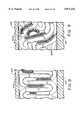
- FIG. 6fragmentary, top view of the discharge section of the portion of the machine shown in FIGS. 4 and 5.
- FIG. 7is an enlarged, fragmentary view of the cutting area of the machine shown in FIGS. 4, 5 and 6.
- FIG. 8is a fragmentary, sectional view as seen along Line VIII--VIII of FIG. 6.
- FIG. 9is a fragmentary, sectional view as seen along Line IX--IX of FIG. 6.
- FIG. 10is a fragmentary, side view of a representative generally compressed strip of material of the prior art at a first predetermined time after formation thereof.
- FIG. 11is a fragmentary, side view of the same representative generally compressed strip of material of FIG. 10 after being allowed to relax for an additional predetermined amount of time.
- FIG. 12is a fragmentary, side view of a preferred representative generally compressed strip of material including various features of the invention at the first predetermined time after formation thereof to demonstrate its characteristics as compared to the strip of material shown in FIG. 10.
- FIG. 13is a fragmentary, side view of the preferred representative generally compressed strip of material of FIG. 12 after being allowed to relax for the same additional predetermined amount of time as occurs with the strip of material of FIG. 11 for a comparison thereof.
- FIG. 14is a schematic overall view of the steps of the method of the present invention.
- FIG. 1includes additional framing, bracketing and adjustment means which are well known in the printing and paper art for the supply and advancement of large sheets of paper from a roll.
- bracketing and adjustment meanswhich are well known in the printing and paper art for the supply and advancement of large sheets of paper from a roll.
- various bearings for supporting rollers and insuring free rotation thereofhave been omitted.
- the preferred method and apparatus of the present inventionis basically provided by a preferred packing paper apparatus 10 including a number of features which can be found in the prior art machines disclosed in U.S. Pat. No. 5,088,972 and U.S. application Ser. No. 538,181.
- the preferred apparatus 10 for forming packing productincludes a feed section 12 for supplying a large quantity of sheet paper 14 from a roll 16.
- the method of mounting and exchanging such large rolls 16is well known in the paper art.
- the roll 16includes sheet paper 14 having a transverse width of about 60 inches.
- the sheet paper 14, as will be seen,is slit into three separate longitudinal segments 30, 32, 34 and then redirected to provide three layers paper material 100 for advancement toward a preferred machine 200.
- the machine 200includes a feeding section 202, a cutting section 204 and a discharge section 206.
- the large sheets of paper 14are directed from the lower portion of the rolls 16 around a lower guide roller 60 through a preferred wetting or moistening system 20. From the moistening system 20, the sheet paper 14 is directed further upwardly to layering means 22 for longitudinally cutting and layering the sheet paper 14.
- the layering means 22includes two longitudinal cutters 24 which basically divide the sheet paper 14 into three longitudinal segments 30, 32, 34. The longitudinal segments 30, 32, 34 are respectively reoriented about diagonal bars 40, 42, 44. The reorientation of the segments 30, 32, 34 result in a layering thereof to form combined layers of paper material 100.
- the paper material 100is then directed to the machine 200 for formation of the pecking product as described hereinbelow.
- the preferred apparatus 10includes features which are generally found in U.S. Pat. No. 5,088,972 and U.S. application Ser. No. 538,181 with the exception of the wetting or dampening system 20.
- the preferred wetting or dampening system 20includes an elongated open container 50 which extends throughout the length of the sheet paper 14 passing thereby.
- a continuous supply of wateris provided to the container 50 from a reservoir 52 having a supply pump 54 with an associated supply line 56.
- the water added to the container 50is allowed to overflow through a return line 58 at the other end thereof. Consequently, fresh water may be added to the container 50 with the excess water being returned to the reservoir 52.
- the paper 14is first directed around the lower guide roller 60 at the lower region of the wetting and dampening system 20.
- the sheet paper 14 passing from the guide roller 60 to the longitudinal cutters 24 of the layering means 22is directed by a wetting roller 62.
- the wetting roller 62is mounted to extend into the water within the container 50 and to be rotated by a motor 64 and associated drive means 66.
- the drive means 66includes a drive timing pulley at the output of the motor 64 and a driven timing pulley at the end of the wetting roller 62 with a timing belt extending therebetween.
- the motor 64includes means for varying the speed thereof to regulate the rotation of the wetting roll 64 in a direction indicated by the arrow with the movement of the sheet paper 14 thereby.
- the rotation of the wetting roller 62causes water in the container 50 to be deposited on the cylindrical surface thereof and then transferred to the sheet paper 14 as it passes over the cylindrical surface of the wetting roller 62.
- the actual position of the wetting roller 62can be adjusted through the movement of the end mounts 68 which are shown in FIG. 2 and 3 but omitted from FIG. 1.
- the end mounts 68can be adjustably rotated about a pivot 70 through the positioning of an adjustment bolt 72 in opposition to biasing spring 74. As a result, the amount of water being added to the sheet paper 14 can be adjusted by two means.
- the increase in speed of the motor 64would result in faster rotation of the wetting roller 62 to transfer more water to the sheet paper 14. Additionally, by the selective movement of the end mounts 68, greater pressure can be applied to the sheet paper 14 passing over the cylindrical surface of the wetting roller 62 for further insuring that water will be directed to the sheet paper 14 to increase the moisture thereof.
- the moistened sheet paper 14, as seen in FIG. 3, upon passing by the wetting roller 62is directed upwardly to the adjustable longitudinal cutters 24 for reorientation about a backing roller 80.
- Each of the longitudinal cuttersis mounted on a rod 62 extending along the entire length of the sheet paper 14.
- An adjusting means 84can be utilized to increase the pressure on each cutter 24 to insure a full longitudinal cut of the moistened sheet paper 14.
- Each of the longitudinal cutters 24is aligned with a urethane surface portion (not shown) in order to provide an appropriate backing for the cutting action produced by the longitudinal cutter 24.
- each of the longitudinal segments 30, 32, 40 of paperare moistened prior to their being advanced around the diagonal bars 40, 42, 44. As the segments are rejoined for advancement to the machine 200, they form the preferred three layers of the moistened paper material 100.
- the preferred embodiment of the inventionincludes the machine 200 for forming the preferred improved packing product which is similar to that disclosed in U.S. application Ser. No. 538,181.
- the preferred machine 200has been adapted to increase the width to about 20 inches compared to that of the machine disclosed in U.S. application Ser. No. 538,181 which had a width of about 15 inches.
- other modifications to the preferred machinecould be made to provide alternative configurations which are outside the scope of the present invention.
- the preferred machine 200includes the feeding section 202, the cutting section 204 and the discharge section 206.
- the feeding section 202is configured to feed one or more sheets of paper material to the cutting section 204 to be longitudinally cut thereby.
- the strip means cut by the cutting section 204are then discharged from the cutting section 204 to the discharge section 206 and allowed to dry.
- a feeding motor 208is included in the feeding section 202.
- the feeding motor 208has an associated reduction gear section 210 with a reduction gear output in the form of a drive sprocket 212.
- a cutting motor 214is provided with an associated reduction gear section 216.
- the output of the reduction gear section 216is in the form of a drive sprocket 218.
- the moistened paper material 100 for forming the preferred packing materialis preferably supplied from the supply section 12 to provide one or more layers of the moistened paper material 100 to the feeding section 202.
- the material 100is initially directed for alignment through redirecting rollers 219.
- three layers of the moistened paper material 100are preferably provided by the supply section 12.
- the feeding section 202is configured for longitudinally advancing the moistened paper material 100 in a first direction A.
- a first drive roller 220feeds the moistened paper material 100 to a transverse cutting component 222.
- the transverse cutting component 222includes four rotating cutting blades 224 which are mounted for rotation on a shaft 225.
- a back-up cylinder 226is in alignment with the shaft 225 and includes neoprene sections 228 for specific alignment and cooperation with the blades 224.
- each of the preferred blades 224includes a generally serrated edge but also includes several gaps along the lengths thereof in order to provide only a partial cut of the moistened paper material 100 as it is transferred thereunder.
- the moistened paper material 100With the moistened paper material 100 being only partially cut to define sheets 238 which are partially attached to the remainder of the material 100, it is advanced to a second drive roller 230 for further direction to the cutting section 204.
- a first biased roller means 221is biased toward and in alignment with the first drive roller 220.
- a second biased roller means 231is biased toward and in alignment with the second drive roller 230.
- the first drive roller 220, the backing cylinder 226 and the second drive roller 230all rotate at the same rotational speed.
- Each of the components in the feeding section 202are preferably greater than 20 inches wide in order to provide the moistened paper material 100 to the cutting section 204 which, as will be seen, is also capable of accommodating paper material 20 inches wide.
- the first drive roller 220is preferably knurled or rough to provide sufficient friction for advancing the moistened paper material 100 therethrough while the second drive roller 230 is preferably smooth.
- the second drive roller 230has a slightly larger diameter than the first drive roller 220 in order to keep the moistened paper material 100 tight for proper partial cutting by the transverse cutting component 222. Because of the smooth surface for roller 230, the additional tension created by the slightly larger second drive roller 230 is not sufficient to actually tear or separate the resulting sheets 238 of moistened paper material 100 from the remainder thereof simply by the action of the drive rollers 220, 230.
- the second drive roller 230includes a driven sprocket 232 rigidly mounted on the end thereof for driving connection with a chain drive 213 from the drive sprocket 212.
- a gear 232a on the shaft of the second drive roller 230is in engagement with and rotates a first idler gear 233 mounted on the side housing of the feeding section 202.
- the first idler gear 233is in turn in engagement with a gear 234 associated with a backing cylinder 226.
- the gear 234is in engagement with a second idler gear 236 and with a larger gear 239 connected to the rotating shaft 225 of the cutting blades 224.
- the gear 239has a diameter which is twice that of the gear 234 in order to produce rotation of the shaft 225 at one half of the speed of the backing cylinder 226. Consequently, the four cutting blades 224 are brought into alignment with the two neoprene sections 228 of the backing cylinder 226 as they rotate at correspondingly different speeds.
- the second idler gear 236is in engagement with and rotates the drive gear 237 on the end of the first drive roller 220.
- the gearingcould be altered to allow the backing cylinder to have a larger diameter so that there could be included three neoprene sections thereon.
- the larger backing cylindercould provide greater stability throughout the width of the machine as there is being produced the desired transverse cut by the cutting blades extending transversely of the moistened paper material 328 as it advances longitudinally through the feeding section.
- the feeding motor 208is a variable speed motor with the reduction gear section 210 having a reduction gear ratio of ten to one.
- the motor 208is preferably set to produce a feeding of the moistened paper material 100 having a width of about 20 inches at a speed of about 360 feet per minute.
- the spacing of the cutting blades 224 around the shaft 225is such that the partial cut is produced every 4.4 inches along the length of the moistened paper material 100.
- the preferred sheets 238 of moistened paper material 100 to be longitudinally fed to the cutting sectionare 20 inches wide and 4.4 inches long.
- the cutting section 204includes an upper and lower set of overlapping cutting discs 240, 242.
- the upper cutting discs 240are fixedly mounted for rotation on a shaft 241 while the lower cutting discs 242 are fixedly mounted for rotation on a shaft 243.
- the lower shaft 243includes a driven sprocket (not shown) and is connected by a chain 219a to the drive sprocket 218 of the cutting motor 214.
- the shafts 241, 243are coupled by matching gears (not shown) for corresponding rotation in the opposite direction as generally indicated by the arrows B.
- the overlapping and interengagement of the discs 240, 242are such that adjacent cutting discs 240, 242 on their respective shafts 241, 243 are separated one from the other for receipt of a cutting disc 242, 240 on the other shaft 243, 241 therebetween.
- the array of overlapping cutting discs 240, 242are capable of receiving therebetween each sheet 238 of the moistened paper material 100, whether there is one or more layers, from the feeding section 202. Once directed between the cutting discs 240, 242, the sheets 238 are longitudinally cut, in the direction A, into moistened strip means with each moistened strip means including a corresponding number of layers as the original sheets 238 supplied by the feeding section 202.
- the sheets 238are generally cut to form elongated moistened strip means associated with each cutting disc 240, 242.
- the cutsare produced between the side edges of each cutting disc 240 and the adjacent side edges of the adjacent cutting disc 242.
- the moistened strip means produced by the cutting discs 240, 242are generally maintained in alignment for passage through the cutting section 204 by an array of combers 244 associated with each set of cutting discs 240, 242.
- Each comber 244includes a central opening 245 for receipt of the corresponding shaft 241, 243 therethrough.
- the combers on one shaft 241, 243are laterally or transversely aligned with corresponding cutting discs 242, 240 on the other shaft 243, 241.
- Each comber 244is mounted on and supported by transverse bars 246 extending across the cutting section 204 through corresponding holes in the end of the comber 244. Despite the support by the rods 246, the preferred combers 244 are capable of limited movement along the shafts 241, 243 in the same manner as the cutting discs 240, 242.
- each of the combers 244includes an end face 248 in alignment with the corresponding cutting disc 240, 242 on the opposite shaft 241, 243.
- the configuration of cutting discs 240, 242 and aligned end faces 248 of the combers 244produces a general region for restricted movement of the moistened strip means formed by the cutting section 204 as the sheets 238 pass therethrough.
- the aligned end face 248terminates at an extension 250 of each comber 244 at the discharge side of the cutting section 204. The purpose of the extensions 250 will be discussed hereinbelow.
- the cutting section 204is powered by the motor 214 with variable speed control and includes the reduction gear 216 with a six to one reduction ratio.
- Each of the cutting discs 240, 242is about 1/8 of an inch wide. Accordingly, each cutting shaft 241, 243 includes at least eighty cutting discs 240, 242 thereon to provide a total of at least one hundred and sixty cutting discs 240, 242 for the two sets to produce the desired cutting of the sheets 238 which are 20 inches wide.
- the speed of the motor 214is adjusted to provide a speed at the outer cylindrical surface of each cutting disc 240, 242 of about 380 feet per minute. In other words, tube cutting discs 240, 242 are rotating at a linear speed faster than the second drive roller 230.
- each sheet 238is pulled from its following adjacent sheet 238 to separate the partially cut sheets 238 for advancement through the cutting section 204.
- the separationhas not yet occurred and tends to occur as the sheet 238 is leaving the second drive roller 230.
- the drive roller 230it is desirable for the drive roller 230 to maintain contact with the following adjacent sheet 238 in order to maintain the tension on the material for transverse cutting. Consequently, each sheet 238, whether having a single or multiple layer of moistened paper material 100, will be longitudinally cut into the moistened strip means in the cutting section 204 prior to the entrance or the next available sheet 238 into the cutting section 204.
- the preferred machine 200must also include some means for restricting the movement of the moistened strip means after their formation in the cutting section 204.
- the discharge section 206is aligned with the cutting section 204 and primarily includes a discharge chute 260.
- the discharge chute 260is maintained in position by framing 258 which is secured at opposite sides of the cutting section 204.
- the preferred discharge chute 260is primarily formed of Plexiglas or some other durable clear plastic material
- the discharge chute 260includes a lower wall 262 and an upper wall 264 with two side walls 266 therebetween.
- a pair of lower brackets 268are secured to the framing 258 to receive and support the lower wall 262 thereon.
- the leading end of each side wall 266is movably secured between the lower wall 262 and the upper wall 264 by bolt means 276.
- adjustable bracketingat the top of the framing 258 for creating a downward force on the upper wall 264.
- brackets 270extend across the top surface of the upper wall 264 and are maintained in place by adjustable bolt means 274 which extend through a rigid bar 272 secured between the side framing 258.
- the bolt means 274are intended, through the brackets 270, to apply reinforcing pressure to the upper wall 264 and the lower wall 262 while also providing significant frictional force on the upper and lower surfaces of the side walls 266.
- this means of applying pressure to the side walls 266is significant when it is understood that this preferred discharge chute 260 can be adjusted to accommodate sheets of moistened paper material having different widths as the moistened strip means formed thereby are discharged from the cutting section 204.
- the discharge section 206as shown in FIG. 6, is intended to receive the strip means formed from sheets of moistened paper material which are about 20 inches wide.
- the feeding section 202 and the cutting section 204could reasonably accommodate sheets of material as narrow as about 15 inches.
- the width provided in the discharge chute of the embodiment disclosed in U.S. application Ser. No. 538,181was narrower because of the intended feeding of narrower sheets of paper material.
- the overall configurationis the same with the chute 260 being adapted to be wider and only modified to withstand the greater forces that may be created because of the increased volume and surface area therein.
- this preferred chute 260must be adjusted for producing sufficient resistance to the moistened strip means discharged from the cutting section 204.
- the mounting of the side walls 266 by the bolt means 276allows the trailing end of each side wall 266 to be rotated to cause the discharge chute 260 to have a narrowing profile.
- the bolts 274can be loosened to reduce the pressure between the brackets 268, 270. With the force reduced on the upper wall 264 and the lower wall 262, each side wall 266 can be rotated about its respective bolt means 276.
- each frame 258is provided with adjustable bolt means 278 for controlled positioning of the side walls 266 about the bolt means 276.
- the side walls 266are shown to be parallel in FIG. 6, for the accommodation of sheets of moistened paper material which are about 20 inches wide, if the sheets of moistened paper material were as narrow as 15 inches, the bolts 278 could be inwardly adjusted to cause the trailing end of the discharge chute 260 to be significantly narrowed to about 15 inches.
- the resulting narrowing profilecan create a reduced volume for the collecting of the moistened strip means therein and for providing significant restrictions on all of the moistened strip means being discharged therethrough.
- the adjustable gate 280at the output end thereof.
- the gate 280is hingedly coupled to the upper wall 264. Bracketing 282 at the opposite ends of the gate 280 can be used for manual or automatic control means (not shown) for the proper positioning of the gate 280.
- the gate 280during continued production of the packing product of the present invention, need not always be in a closed and restricting position.
- the general friction created by the packing product through the discharge chute 260may be sufficient to cause adequate restrictions at the discharge of the cutting section 204 to produce the desired characteristics to the strip means as described hereinbelow.
- the discharge chute 260has an internal height H of about 2 inches and internal width W which can be varied between about 15 and 20 inches. Because of the significant pressure and forces which are generated within the discharge chute 260, the lower wall 262 and the upper wall 264 have a thickness of about 3/4 of an inch while each of the side walls 266 have a thickness of about 1-1/2 inches. While the preferred length of the discharge chute is about 12 inches, the length could be selected depending on the type of material being employed to produce the preferred packing product. The height of 2 inches allows the extensions 250 of each comber 244 to be loosely positioned within the interior of the chute 260 to produce a better transition from the cutting section 204 to the discharge section 206.
- the discharge chute 260is configured for allowing adjustment of the internal width depending on the size of the sheets of material provided thereto, it should be noted that a different, simplified configuration could be employed if the machine is intended to continuously receive sheets having the same width.
- the entire discharge chutemay be formed with rigid and firmly joined top, bottom and side walls.
- the bottom wall of such a discharge chutecould be inclined to slope downwardly from a middle region of the discharge chute to assist in the transition of the completed packing material as it is being discharged from the end of the discharge chute.
- the preferred embodiment, in the form of machine 200does not include any representation of the packing product being formed thereby.
- FIGS. 7, 8 and 9include a representation of what is felt to occur within the interior of the cutting section 204. It should be understood that the preferred machine 200 produces an extremely packed and tight array of moistened strip means which basically comprise the preferred packing product prior to expansion, relaxation and intermixing in the discharge chute 260 and after leaving the discharge chute 260. The plurality of tightly mixed and interconnected strip means produces the packing product in such a compacted form that actual identification of the orientation and configuration of the various moistened strip means within the cutting section 204 and discharge section 206 is quite difficult. However, the best understood representation of the packing product, as it is being formed in the machine 200, is provided in a schematic form in FIGS. 7, 8 and 9.
- the moistened paper material for the formation of the preferred packing productincludes a natural resilience with a tendency to resist folding.
- a material in sheet formis paper, cardboard, mylar or any other material
- such materialtypically includes a tendency to remain in a straightened form and to resist any folds or bends thereof.
- This principlecan be readily observed by simply taking a small sheet of paper and trying to fold it in half. If one attempts to apply pressure to the fold to impart a folded memory to the sheet material, it is not uncommon for the fold to "relax" as the two halves of the paper tend to naturally separate because of the original "memory" in the paper tending to resist the fold. The same principle can also be observed if several layers are also folded at the same time.
- moistened papertends to react in the same general manner but to a different degree. In other words, if the paper is slightly moistened, less force may be required to initially apply the pressure to the fold to impart a folded memory to the moistened sheet material. Additionally, when the fold relaxes as the two halves of the papers tend to naturally separate because of the original "memory" in the paper, the separation is to a lesser degree than that produced in the dry paper. Additionally, because the separation is to a lesser degree, the fold tends to be more stable and, as the paper dries, tends to retain a smaller angle at the fold than would be accomplished over the same period of time at a fold formed in the drier sheet material.
- the present inventionincludes means for providing water to the paper material to provide moisture thereto, it should be recalled that the natural humidity at the production site could include some moisture in the air and thus in the paper material. Consequently, the general humidity at the facility could result in a packing product having preferred characteristics, or on the other hand, could result in a detrimental situation with the packing product having less desired characteristics. While it should be clear that the adjustment of the gate 280 could affect the formation and characteristics of the folds in the strip means produced by the preferred machine, clearly, the inclusion of moistened paper material will enable the desired characteristics to be more simply and readily produced. Further, the inclusion of means for adjusting the amount of moisture within the paper material will allow convenient and reliable reproduction of the desired paper packing product in different facilities even though the different facilities may have different humidity conditions therein.
- each of the folds produced in the preferred strip meansare, at least initially, quite tight so that the adjacent longitudinal portions of the moistened strip means tend to lie in close contact.
- the foldswill have a natural tendency to expand or relax to cause the portions adjacent to folds to angularly separate.
- the moistened sheets 238, as they advance between the cutting wheels 240, 242,are initially cut at the side edges thereof to form initial moistened strip means 300a which tend to lie along the smooth, outer cylindrical surface 240c, 242c of the respective cutting wheels 240, 242.
- the initial moistened strip means 300ais constantly being advanced, at least partially, by the rotating surface 240c, 242c toward the discharge side of the cutting section 204.
- each of the initially formed moistened strip means 300ais provided by a collection of previous formed moistened strip means in the discharge section 206 which will be discussed hereinbelow. It is sufficient initially to understand that a plurality of previously formed strip means are tightly collected at the discharge side of the cutting section 204. Consequently, as each initially formed moistened strip means 300a is advanced through the cutting section 204 by each of the cutting discs 240, 242 applying frictional force thereto, the resistance at the end thereof causes the initially formed moistened strip means 300a to be sequentially folded to provide a longitudinally compressed strip means 300b.
- the longitudinally compressed strip means 300bis formed inherently within the cutting section 204 by previously formed and fully longitudinally compressed strip means 300b collecting at the discharge side thereof.
- the moving collection of fully longitudinally compressed strip means 300bis maintained in position for discharge by the aligned end faces 248 of each of the combers 244 and the extensions 250.
- the view shown in FIG. 7represents the best understanding of the type of collection of the fully longitudinally compressed strip means 300b within the cutting section 204 at the discharge side thereof. While the outer cylindrical surface 240c, 242c does impart some compressive force on each of the initial strip means 300a as the fully longitudinally compressed strip means 300b are being formed, it should also be understood that the side surfaces 240s and 242s of each cutting wheel 240, 242 also apply side frictional forces to each of the fully longitudinally compressed strip means 300b during and after its formation.
- the preferred machine 200differs from the embodiment disclosed in U.S. Pat. No. 5,088,972 by the inclusion of the smooth cylindrical outer surfaces 240c and 242c of the cutting discs 240 and 242.
- the cutting discs of U.S. Pat. No. 5,088,972included the serrated or tooth configuration which could grip material provided thereto and could tend to insure proper longitudinal cutting of the material for the formation of strip means.
- one feature of the device disclosed in U.S. Pat. No. 5,088,972was improved by the inclusion of the smooth outer cylindrical surfaces 240c, 242c because of the type of longitudinal compacting of the various strip means which occurs within the cutting section 204 of the machine 200.
- the smooth outer cylindrical surfaces 240c, 242cdo not tend the tearing and wearing away of the material and significantly reduce the possibility of dust and other fine particles being produced. Further, as seen in FIG. 7, with the tight collection of the fully longitudinally compressed strip means 300b at the outlet side of the cutting discs 240, 242, the smooth edges of the outer surface of the cutting discs can rotate by the previously collected fully longitudinally compressed strip means 300b without excessive side ripping or tearing thereof which would clearly produce an extensive amount of dust particles.
- the moistened strip meansappear to collect in some type of wave form near the entrance end of the discharge chute 260 as tightly longitudinally compressed strip means 300c advance through the discharge chute 260. While the tightly longitudinally compressed strip means 300c have very tight folds therein, it is not expected that their folds will be quite as tight as those of the fully longitudinally compressed strip means 300b as initially formed within the cutting section 204. Clearly, the resistance produced in the discharge chute 260 tending to cause the sequential folding of each of the initial moistened strip means 300a will be greater within the cutting section 204 than at subsequent positions along the discharge chute 260.
- FIG. 8is only a schematic representation of what appears to be occurring at the inlet end of the discharge chute 260 and the waves are probably not as uniform or as evenly positioned.
- the strip means 300cshould still be quite tightly longitudinally compressed but not to the same extent as the fully longitudinally compressed strip means 300b. This tendency to be less longitudinally compressed is fully consistent with the resilient nature of the material used to form the strip means which comprises the basic packing product.
- FIGS. 7 and 8 of the fully longitudinally compressed strip means 300b and the tightly longitudinally compressed strip means 300cwould be similar whether the strip means are dry or moist. Without being able to accurately inspect the interior of the inlet to the discharge chute 260, a similar schematic representation of the strip means whether dry or moist would be expected. Additionally, it should be noted that the same problems concerning an accurate inspection of the interior of the cutting section 204 and the inlet to the discharge chute 260 would prevent an accurate determination of when the moistened strip means will begin to fully dry. It is expected that the moistened strip means will remain moistened for some time within the discharge chute 260 and will be significantly drier by the time the longitudinally compressed strip means discharged from the end thereof.
- the moistened paper materialis believed to he in a condition for the formation of less of the undesired dust material
- the moistened condition of the paper materialmight allow small edge particles thereof to be reconstituted or joined with the remainder of the strip means as such strip means tends to dry. Consequently, the moistened strip means should result in less dust particles being formed and in less dust particles being entrapped within the packing material as the individual compressed strip means begin to dry and migrate toward the exit of the discharge chute 260.
- the less longitudinally compressed strip means 300dwill further dry and include less moisture than when originally formed as strip means within the cutting section 204.
- the pressure on the less longitudinally compressed strip means 300dtends to reduce, because of the opening at the discharge end of the discharge chute 260, the natural resilience of each strip means tends to cause them to expand and to be relatively repositioned within the discharge chute 260.
- each longitudinally compressed strip meansdoes not include simply a shredding machine configuration for forming a collection of strip means which is compressed to form a packing product.
- the preferred packing productis composed of a plurality of individually longitudinally compressed strip means which tend to expand in an interlocking and resilient manner to provide the resulting packing product with individual strip means having natural resilience, a tendency to longitudinally expand, and a tendency to resist lateral or side forces.
- FIG. 10Shown in FIG. 10 is a representative longitudinally compressed strip of paper material 300 of the prior art.
- the generally compressed strip of material 300is not, by any means, identical to all of the strips formed by the prior art process. Obviously, other such strips would include different generally acute angles between the adjacent planar portions thereof and have such portions with different lengths. Nevertheless, the strip of paper material 300 is representative and includes typical characteristics for the purpose of comparison with a similar representative longitudinally compressed strip of material 400 which would be formed through the use of the preferred method and apparatus of the present invention. Accordingly, the strip of material 300 at a first predetermined time after being ejected from the discharge chute could include a typical angle R at the folds thereof.
- the same strip of material 300would be allowed to relax to generally cause expansion thereof with a relatively larger acute angle S at the folds thereof.
- a similar preferred representative longitudinally compressed strip of material 400is formed by the preferred method and apparatus of the present invention to have similar lengths of adjacent planar portions between the folds thereof.
- the angle T at the fold thereofwould be less than the corresponding angle R of the strip of material 300.
- the introduction of moisture to the paper materialwill cause the resulting strip of material 400 to more readily fold and have a tendency to include smaller angles at the folds thereof.
- the expansion of the strip of material 400would be such that the angle U at the folds thereof would be less than the angle S at the folds of the comparable, prior art strip of material 300 shown in FIG. 11.
- the preferred packing product of both the prior art and the present inventioninclude a plurality of interlocking such strips of material which continuously have a tendency to expand. Accordingly, the strips of material 300 and 400 as shown in FIGS. 11 and 13 have been basically removed from the interlocking plurality of similar strips in order to demonstrate the tendency thereof to expand when allowed to fully relax without the resistence created by being interlocked with additional such strips.
- the use of the preferred method and apparatus of the present inventionresults in a more tightly formed longitudinally compressed strip of material 400 which has a tendency to maintain the angles at the folds thereof with the passage of time.
- the preferred method and apparatus of the present inventionenables control during the formation of the longitudinally compressed strips of material independent of the moisture condition of the facility in which they are being formed to insure the quality of the strips of material as described. While there is clearly a desire to have separation between the adjacent planar portions of the strip of material at each side of the folds thereof, it is nevertheless important to insure that the acute angle at the fold is sufficiently small to maintain the tendency to longitudinally expand and the tendency to resist lateral or side forces. Obviously, if the angle at the fold is allowed to expand to an obtuse angle, the ability to expand is reduced and the ability to resist lateral or side forces would be significantly limited.
Landscapes
- Life Sciences & Earth Sciences (AREA)
- Health & Medical Sciences (AREA)
- Engineering & Computer Science (AREA)
- Chemical & Material Sciences (AREA)
- Hematology (AREA)
- Urology & Nephrology (AREA)
- Biomedical Technology (AREA)
- Molecular Biology (AREA)
- Immunology (AREA)
- Analytical Chemistry (AREA)
- Biotechnology (AREA)
- Cell Biology (AREA)
- Mechanical Engineering (AREA)
- Forests & Forestry (AREA)
- Microbiology (AREA)
- Environmental Sciences (AREA)
- General Physics & Mathematics (AREA)
- Food Science & Technology (AREA)
- Medicinal Chemistry (AREA)
- Physics & Mathematics (AREA)
- Pathology (AREA)
- Biochemistry (AREA)
- General Health & Medical Sciences (AREA)
- Zoology (AREA)
- Inorganic Chemistry (AREA)
- Biodiversity & Conservation Biology (AREA)
- Animal Husbandry (AREA)
- Machines For Manufacturing Corrugated Board In Mechanical Paper-Making Processes (AREA)
- Making Paper Articles (AREA)
- Buffer Packaging (AREA)
- Gasket Seals (AREA)
- Containers And Plastic Fillers For Packaging (AREA)
- Folding Of Thin Sheet-Like Materials, Special Discharging Devices, And Others (AREA)
- Shaping Of Tube Ends By Bending Or Straightening (AREA)
Abstract
Description
Claims (17)
Priority Applications (5)
| Application Number | Priority Date | Filing Date | Title |
|---|---|---|---|
| US08/153,491US5871432A (en) | 1992-03-31 | 1993-11-17 | Method and apparatus for making an improved resilient packing product |
| US08/345,524US5830765A (en) | 1993-09-22 | 1994-11-28 | Feline urinary tract disease-detecting paper cat litter and method |
| US08/444,956US5780385A (en) | 1992-03-31 | 1995-05-19 | Feline urinary tract disease-detecting paper cat litter and method |
| US08/459,347US5656008A (en) | 1992-03-31 | 1995-06-02 | Method and apparatus for making an improved resilient packing product |
| US08/459,495US5921907A (en) | 1992-03-31 | 1995-06-02 | Method and apparatus for making an improved resilient packing product |
Applications Claiming Priority (2)
| Application Number | Priority Date | Filing Date | Title |
|---|---|---|---|
| US86122592A | 1992-03-31 | 1992-03-31 | |
| US08/153,491US5871432A (en) | 1992-03-31 | 1993-11-17 | Method and apparatus for making an improved resilient packing product |
Related Parent Applications (2)
| Application Number | Title | Priority Date | Filing Date |
|---|---|---|---|
| US86122592AContinuation | 1992-03-31 | 1992-03-31 | |
| US86122592AContinuation-In-Part | 1992-03-31 | 1992-03-31 |
Related Child Applications (3)
| Application Number | Title | Priority Date | Filing Date |
|---|---|---|---|
| US08/345,524Continuation-In-PartUS5830765A (en) | 1992-03-31 | 1994-11-28 | Feline urinary tract disease-detecting paper cat litter and method |
| US08/459,347ContinuationUS5656008A (en) | 1992-03-31 | 1995-06-02 | Method and apparatus for making an improved resilient packing product |
| US08/459,495ContinuationUS5921907A (en) | 1992-03-31 | 1995-06-02 | Method and apparatus for making an improved resilient packing product |
Publications (1)
| Publication Number | Publication Date |
|---|---|
| US5871432Atrue US5871432A (en) | 1999-02-16 |
Family
ID=25335223
Family Applications (3)
| Application Number | Title | Priority Date | Filing Date |
|---|---|---|---|
| US08/153,491Expired - LifetimeUS5871432A (en) | 1992-03-31 | 1993-11-17 | Method and apparatus for making an improved resilient packing product |
| US08/459,495Expired - LifetimeUS5921907A (en) | 1992-03-31 | 1995-06-02 | Method and apparatus for making an improved resilient packing product |
| US08/459,347Expired - LifetimeUS5656008A (en) | 1992-03-31 | 1995-06-02 | Method and apparatus for making an improved resilient packing product |
Family Applications After (2)
| Application Number | Title | Priority Date | Filing Date |
|---|---|---|---|
| US08/459,495Expired - LifetimeUS5921907A (en) | 1992-03-31 | 1995-06-02 | Method and apparatus for making an improved resilient packing product |
| US08/459,347Expired - LifetimeUS5656008A (en) | 1992-03-31 | 1995-06-02 | Method and apparatus for making an improved resilient packing product |
Country Status (8)
| Country | Link |
|---|---|
| US (3) | US5871432A (en) |
| EP (1) | EP0633839B1 (en) |
| JP (1) | JP2691075B2 (en) |
| AT (1) | ATE154285T1 (en) |
| AU (1) | AU3808793A (en) |
| CA (1) | CA2133420C (en) |
| DE (1) | DE69311543T2 (en) |
| WO (1) | WO1993019931A1 (en) |
Cited By (40)
| Publication number | Priority date | Publication date | Assignee | Title |
|---|---|---|---|---|
| US5943244A (en)* | 1997-02-17 | 1999-08-24 | I2 Technologies, Inc. | System for optimizing a network plan and method of operation |
| US6033353A (en)* | 1997-02-26 | 2000-03-07 | Ranpak Corp. | Machine and method for making a perforated dunnage product |
| US6190783B1 (en) | 1997-07-11 | 2001-02-20 | Southpac Int'l, Inc. | Folded corrugated decorative grass formed of laminates and combinations of material |
| US6221000B1 (en) | 1997-07-11 | 2001-04-24 | Southpac Trust Int'l, Inc. | Folded corrugated material |
| US6299960B1 (en) | 1997-07-11 | 2001-10-09 | Southpac Trust Int'l, Inc. | Decorative grass formed of polymeric materials having a texture and appearance assimilating paper |
| US6402675B2 (en) | 1997-07-11 | 2002-06-11 | Southpac Trust International, Inc. | System for producing corrugated decorative grass |
| US6401430B2 (en) | 1998-06-17 | 2002-06-11 | Southpac Trust International, Inc. | Sleeves formed of polymeric materials having a texture or appearance simulating the texture or appearance of paper |
| US6406651B1 (en) | 1997-06-26 | 2002-06-18 | Southpac Trust Int'l. Inc. | Method for forming decorative grass having an appearance assimilating the appearance of paper |
| US6425967B1 (en) | 1997-06-26 | 2002-07-30 | Southpac Trust International, Inc | Method of making decorative grass having a cloth-appearing finish on a surface thereof |
| US6425224B1 (en) | 1998-09-14 | 2002-07-30 | Southpac Trust International, Inc. | Sleeves formed of polymeric materials having a texture or appearance simulating the texture or appearance of paper |
| US20020109255A1 (en)* | 1997-07-14 | 2002-08-15 | Weder Donald E. | Method for making printed and/or embossed decorative grass |
| US6436324B1 (en) | 1997-06-19 | 2002-08-20 | Southpac Trust International, Inc. | Method for making curled decorative grass |
| US6468196B1 (en) | 1998-07-09 | 2002-10-22 | Southpac Trust International, Inc. | Synthetic decorative grass simulating Spanish moss and method for making same |
| US6491997B1 (en) | 1997-06-26 | 2002-12-10 | Southpac Trust International, Inc. | Decorative grass formed of polymeric materials having a texture and appearance assimilating paper |
| US6511735B1 (en) | 1997-06-26 | 2003-01-28 | Southpac Trust International, Inc. | Decorative grass having an appearance simulating the appearance of cloth |
| US20030024624A1 (en)* | 1997-02-07 | 2003-02-06 | Weder Donald E. | Decorative elements provided with a circular or crimped configuration at point of sale or point of use |
| US6544620B2 (en) | 2000-08-10 | 2003-04-08 | Southpac Trust International, Inc. | Decorative grass formed of cloth and polymeric film |
| US20030082317A1 (en)* | 1997-07-14 | 2003-05-01 | Weder Donald E. | Decorative grass formed of cloth and cloth laminated to paper |
| US20030111761A1 (en)* | 1998-04-10 | 2003-06-19 | Weder Donald E. | Method for making printed and/or embossed decorative grass |
| US6588149B2 (en) | 1997-06-26 | 2003-07-08 | Southpac Trust International, Inc. | Ribbon formed of cloth and polymeric film |
| US6588309B2 (en) | 1997-11-10 | 2003-07-08 | Donald E. Weder | Decorative grass having a three-dimensional pattern and methods for producing same |
| US20030196742A1 (en)* | 1997-02-07 | 2003-10-23 | Weder Donald E. | Synthetic decorative moss simulating Spanish moss and method for making same |
| US6645408B2 (en) | 2000-02-07 | 2003-11-11 | Southpac Trust International, Inc. | Method for making curled decorative grass having a texture or appearance simulating the texture or appearance of paper |
| US6656593B1 (en) | 2000-07-07 | 2003-12-02 | Southpac Trust International, Inc. | Scented decorative grass having an appearance simulating the appearance of cloth |
| US6685615B2 (en) | 2001-02-08 | 2004-02-03 | Southpac Trust International, Inc. | Corrugated decorative grass formed of paper and polymeric film and method for producing same |
| US20040022966A1 (en)* | 1997-06-26 | 2004-02-05 | Weder Donald E. | Scented decorative grass formed of polymeric materials having a texture or appearance simulating the texture or appearance of paper |
| US20040058097A1 (en)* | 1999-06-11 | 2004-03-25 | Weder Donald E. | Curled or crimped decorative grass having an optical effect |
| US20040175519A1 (en)* | 2002-10-01 | 2004-09-09 | Weder Donald E. | Self erecting pot |
| US20050214513A1 (en)* | 1998-03-18 | 2005-09-29 | Weder Donald E | Decorative shredded material |
| US20060027311A1 (en)* | 1997-02-07 | 2006-02-09 | The Family Trust U/T/A | Decorative elements provided with a curled or crimped configuration at point of sale or point of use |
| US20060052902A1 (en)* | 2004-08-27 | 2006-03-09 | Neuco, Inc. | Method and system for SNCR optimization |
| US20060281621A1 (en)* | 1997-06-19 | 2006-12-14 | Weder Donald E | Method and apparatus for making curled decorative grass |
| US20070269618A1 (en)* | 1997-07-14 | 2007-11-22 | Weder Donald E | Method for making contoured decorative grass |
| US20080054512A1 (en)* | 1997-06-19 | 2008-03-06 | Weder Donald E | Method and apparatus for making curled decorative grass |
| US20080108454A1 (en)* | 2006-11-06 | 2008-05-08 | Kohnen Michael P | Golf ball containing photoluminescent material and a light source |
| US20090278276A1 (en)* | 1998-04-10 | 2009-11-12 | Weder Donald E | Method for making contoured decorative grass |
| US20110089598A1 (en)* | 2003-02-27 | 2011-04-21 | Weder Donald E | Method for making contoured decorative grass |
| US20110113735A1 (en)* | 1997-06-19 | 2011-05-19 | Weder Donald E | Method for making distorted fragments |
| US20120005989A1 (en)* | 1997-07-14 | 2012-01-12 | Weder Donald E | Packaging material |
| US9707731B2 (en) | 2011-09-30 | 2017-07-18 | FiberCore, LLC | Multi-layered bulk product filling material |
Families Citing this family (25)
| Publication number | Priority date | Publication date | Assignee | Title |
|---|---|---|---|---|
| DE4403751A1 (en)* | 1994-02-08 | 1995-08-10 | Strepp Gmbh & Co Kg Papierfabr | Upholstery material and process for producing this upholstery material |
| ES2093502T3 (en)* | 1994-04-22 | 1996-12-16 | Naturembal Sa | PROCEDURE AND MACHINE FOR THE MANUFACTURE OF FILLING MATERIALS BY WRINKLING PAPER. |
| GB9409973D0 (en)* | 1994-05-18 | 1994-07-06 | Rotech Machines Limited | Packaging material making machine |
| JP3492063B2 (en)* | 1994-12-16 | 2004-02-03 | 株式会社ワタコン | Method and apparatus for manufacturing paper cushioning material |
| US6176818B1 (en) | 1995-06-07 | 2001-01-23 | Ranpak Corp. | Cushioning conversion machine cushioning conversion method and method of assembling a cushioning conversion machine |
| GB2317381B (en)* | 1995-06-07 | 1999-08-18 | Ranpak Corp | Cushioning conversion machine with single feed/cut motor |
| EP0886573B1 (en)* | 1995-06-26 | 2003-02-19 | Ranpak Corp. | Cushioning conversion machine and its use |
| EP0779148A1 (en)* | 1995-12-15 | 1997-06-18 | Tokuji Watanabe | Method and apparatus for manufacturing paper cushioning members |
| AU6182398A (en)* | 1997-02-14 | 1998-09-08 | Ranpak Corp. | Cushioning conversion machine including a length measuring device |
| WO1999016614A1 (en)* | 1997-09-30 | 1999-04-08 | Ranpak Corp. | Method, machine and stock material for making folded strips |
| US5906569A (en)* | 1997-09-30 | 1999-05-25 | Ranpak Corp. | Conversion machine and method for making folded strips |
| US6179765B1 (en) | 1998-10-30 | 2001-01-30 | Ft Acquisition, L.P. | Paper dispensing system and method |
| US20040102302A1 (en)* | 2002-11-27 | 2004-05-27 | Stepanek Stephen B. | Tissue curly cued packaging materials and the method for manufacture thereof |
| US6910997B1 (en)* | 2004-03-26 | 2005-06-28 | Free-Flow Packaging International, Inc. | Machine and method for making paper dunnage |
| US20080115733A1 (en)* | 2006-11-21 | 2008-05-22 | Alfa-Pet, Inc. | Animal bedding and method of manufacture |
| TW201718380A (en) | 2012-07-26 | 2017-06-01 | 居間膠帶聚合物公司 | Tape dispenser with improved wetting system |
| JP6734041B2 (en)* | 2015-11-10 | 2020-08-05 | 三菱重工機械システム株式会社 | Humidifier and corrugating machine |
| CA3029494C (en)* | 2016-06-30 | 2020-10-13 | Ranpak Corp. | Dunnage conversion machine and method |
| DE102016114719A1 (en)* | 2016-08-09 | 2018-02-15 | Progress Packaging Gmbh | Apparatus and method for producing filler material |
| AU2017344024B2 (en) | 2016-10-11 | 2022-07-21 | Sealed Air Corporation (Us) | Machine and method for producing void fill packaging material |
| CN106945115B (en)* | 2017-04-28 | 2019-05-17 | 亨内基机械(上海)有限公司 | A kind of feed system of compound sandwich board assembly line |
| JP7240880B2 (en)* | 2019-01-17 | 2023-03-16 | 三菱重工機械システム株式会社 | Sheet moisturizing apparatus and method, and corrugated cardboard sheet manufacturing apparatus |
| CN112050596B (en)* | 2020-08-28 | 2021-11-16 | 泉州台商投资区飞翔机械设计服务中心 | High efficiency drying device that dyes cloth |
| CN115715527B (en)* | 2023-01-10 | 2023-03-28 | 四川省畜牧科学研究院 | Modular cowshed system and installation method thereof |
| CN118560100B (en)* | 2024-08-02 | 2024-10-18 | 泉州市铭兴塑料包装有限公司 | Zipper bag tailoring equipment |
Citations (67)
| Publication number | Priority date | Publication date | Assignee | Title |
|---|---|---|---|---|
| US1680203A (en)* | 1924-04-07 | 1928-08-07 | William H Cannard | Crepe and method of and apparatus for making the same |
| US1985676A (en)* | 1933-01-28 | 1934-12-25 | Leslie T Hand | Method of and machine for slitting and stacking folded plies of paper web |
| US2045498A (en)* | 1933-02-01 | 1936-06-23 | Chicopee Mfg Corp | Method of conditioning regenerated cellulose for use in the arts |
| US2271180A (en)* | 1939-05-22 | 1942-01-27 | Delwin A Brugger | Packing and cushioning element |
| US2537026A (en)* | 1948-01-08 | 1951-01-09 | Delwin A Brugger | Device for forming flexible packing and cushioning elements |
| GB666225A (en)* | 1948-07-28 | 1952-02-06 | Pollux Trust Vaduz Fa | Improvements in or relating to machines for the manufacture of padded paper |
| US2621567A (en)* | 1949-05-23 | 1952-12-16 | Filemon T Lee | Paper shredding machine |
| US2668573A (en)* | 1947-04-08 | 1954-02-09 | Larsson Olof Einar | Apparatus and process for corrugating paper |
| US2686466A (en)* | 1951-05-15 | 1954-08-17 | Filemon T Lee | Paper shredder and press |
| US2697887A (en)* | 1950-12-07 | 1954-12-28 | Kershaw Royce | Auger type ballast excavator |
| US2770302A (en)* | 1952-01-08 | 1956-11-13 | Filemon T Lee | Machine for shredding paper or the like into strips |
| US2786399A (en)* | 1952-03-06 | 1957-03-26 | Veyne V Mason | Formation of crumpled sheet material filter elements and the like |
| GB771877A (en)* | 1954-10-29 | 1957-04-03 | J F Bas & Cie | Improvements relating to granulating or comminuting machines |
| US2825556A (en)* | 1954-09-01 | 1958-03-04 | Du Pont | Open-width fabric piling apparatus |
| US2865080A (en)* | 1953-10-28 | 1958-12-23 | Du Pont | Method and apparatus for crimping and relaxing filaments |
| US2924154A (en)* | 1956-08-27 | 1960-02-09 | Luber Finer Inc | Method and apparatus for crumpling paper |
| US2968857A (en)* | 1957-07-30 | 1961-01-24 | Celanese Corp | High bulk filamentary material and methods of producing the same |
| US2984399A (en)* | 1957-07-30 | 1961-05-16 | Vanant Company Inc | Packaging strip having accordion pleated cushions |
| US3126095A (en)* | 1964-03-24 | Debundlized tow | ||
| US3150576A (en)* | 1961-08-09 | 1964-09-29 | Wood Marc Sa | Process and apparatus for forming transverse corrugations of all forms in a sheet or band of malleable material |
| US3217988A (en)* | 1963-08-09 | 1965-11-16 | William E Lightfoot | Rotary cutting devices |
| US3235442A (en)* | 1962-07-30 | 1966-02-15 | Du Pont | Crimped tow of polyester filaments |
| US3398223A (en)* | 1963-06-24 | 1968-08-20 | Glanzstoff Ag | Process for production of crimped filaments |
| US3501565A (en)* | 1967-02-23 | 1970-03-17 | Johnson & Johnson | Method of transverse stretching orientable sheet material |
| US3509797A (en)* | 1967-05-22 | 1970-05-05 | Arpax Co | Mechanism for producing cushioning dunnage |
| US3514096A (en)* | 1967-10-25 | 1970-05-26 | Gaf Corp | Copy paper feeding and refolding guide |
| US3567119A (en)* | 1969-10-06 | 1971-03-02 | Godfrey Wilbert | Enhanced diffusion of odor vapor from polymers |
| US3613522A (en)* | 1969-09-12 | 1971-10-19 | Arpax Co | Method of producing cushioning dunnage |
| US3650877A (en)* | 1969-10-06 | 1972-03-21 | Arpax Co | Cushioning dunnage product |
| US3754498A (en)* | 1971-12-17 | 1973-08-28 | R Gil | Apparatus for shredding and baling paper |
| US3859695A (en)* | 1973-01-05 | 1975-01-14 | Phillips Petroleum Co | Stuffer box control |
| US3905057A (en)* | 1973-07-06 | 1975-09-16 | Cww Research And Dev Company | Fiber-filled pillow |
| US4012932A (en)* | 1974-06-06 | 1977-03-22 | Marc Wood S.A. | Machine for manufacturing herringbone-pleated structures |
| US4075746A (en)* | 1976-06-16 | 1978-02-28 | Kling-Tecs, Inc. | Compression crimping apparatus |
| US4085662A (en)* | 1975-05-01 | 1978-04-25 | Ranpak Corporation | Method of making and using cushioning dunnage material |
| US4091766A (en)* | 1974-07-29 | 1978-05-30 | Colliard Lynette K | Pet collar |
| US4132155A (en)* | 1976-09-16 | 1979-01-02 | Marvin Glass & Associates | Paper craft kit |
| US4201128A (en)* | 1977-09-02 | 1980-05-06 | Gardner Thomas H | Apparatus for the compacting and treatment of materials such as shredded paper |
| US4247289A (en)* | 1979-11-02 | 1981-01-27 | Mccabe James E | Paper spring method |
| US4313899A (en)* | 1980-02-07 | 1982-02-02 | Champion International Corporation | Process for forming laminated paperboard containers |
| US4410315A (en)* | 1980-10-03 | 1983-10-18 | Beloit Corporation | Low velocity trim removal means and method |
| US4551126A (en)* | 1983-11-09 | 1985-11-05 | Wayne Automation Corp. | Method of carton flap relaxing |
| US4597748A (en)* | 1984-10-04 | 1986-07-01 | Wolf Robert A | Method and apparatus for forming gauze pads |
| US4619862A (en)* | 1983-02-02 | 1986-10-28 | Kimberly-Clark Corporation | Particulate paper product, especially for use as animal litter |
| US4622028A (en)* | 1980-05-12 | 1986-11-11 | Bunch Jr Ernest B | Delivery mechanism for paper sheet processing apparatus |
| US4650456A (en)* | 1985-10-30 | 1987-03-17 | Ranpak Corp. | Mechanism for producing pad-like cushioning dunnage product from sheet material with separate stock roll cart |
| US4699609A (en)* | 1986-02-25 | 1987-10-13 | Ranpak Corp. | Electric cutter mechanism for dunnage converter |
| US4700939A (en)* | 1986-08-12 | 1987-10-20 | Kimberly-Clark Corporation | Apparatus and process for separating and removing bundles of sheets |
| US4717135A (en)* | 1986-08-12 | 1988-01-05 | Kimberly-Clark Corporation | Apparatus and process for automatically interfolding sheets and separating them into bundles |
| US4718654A (en)* | 1986-02-27 | 1988-01-12 | Paper Converting Machine Company | Apparatus and method for separation and delivery of continuous forms |
| US4741944A (en)* | 1986-07-30 | 1988-05-03 | Kimberly-Clark Corporation | Wet wipe and wipe dispensing arrangement |
| US4806410A (en)* | 1986-09-18 | 1989-02-21 | Ranpak Corp. | Processes for the production of antistatic or static dissipative paper, and the paper products thus produced, and apparatus utilized |
| US4808466A (en)* | 1986-10-09 | 1989-02-28 | Daicel Chemical Industries, Ltd. | Deodorant sheet |
| US4813996A (en)* | 1979-02-21 | 1989-03-21 | Gardner Thomas H | Production of nutrient material |
| US4816320A (en)* | 1986-06-16 | 1989-03-28 | St Cyr Napoleon | Toilet tissue and facial tissue |
| US4868037A (en)* | 1986-10-14 | 1989-09-19 | The Dow Chemical Company | Insulated articles containing non-linear carbonaceous fibers |
| US4889755A (en)* | 1988-11-01 | 1989-12-26 | Minnesota Mining And Manufacturing Company | Fragrance releasing pull-out sampler |
| US4923745A (en)* | 1989-04-07 | 1990-05-08 | Barbara Wolfert | Insect repellent clothing bag |
| US4957063A (en)* | 1988-07-25 | 1990-09-18 | The Clorox Company | Odor control animal litter |
| WO1991006694A1 (en)* | 1989-11-02 | 1991-05-16 | Eco-Pack Industries, Inc. | Resilient packing product |
| US5016568A (en)* | 1989-06-23 | 1991-05-21 | The Clorox Company | Odor controlling animal litter with pine oil |
| US5018482A (en)* | 1988-06-17 | 1991-05-28 | The Clorox Company | Combined odor controlling animal litter |
| US5088972A (en)* | 1989-11-02 | 1992-02-18 | Eco-Pack Industries, Inc. | Folding and crimping apparatus |
| US5097799A (en)* | 1988-07-25 | 1992-03-24 | The Clorox Company | Odor control animal litter containing sodium fluoride |
| US5100600A (en)* | 1989-12-09 | 1992-03-31 | Fritz Keller | Method of making an absorbent paper-containing granulate |
| US5102715A (en)* | 1987-01-23 | 1992-04-07 | Lars Zetterquist | Label with bactericidal agent for prolonging the life of cut flowers |
| US5181614A (en)* | 1991-04-05 | 1993-01-26 | Ridley Watts | Coil dunnage and package using same |
Family Cites Families (4)
| Publication number | Priority date | Publication date | Assignee | Title |
|---|---|---|---|---|
| US2679887A (en)* | 1949-07-22 | 1954-06-01 | Arkell Safety Bag Co | Method of making crinkled laminated material |
| US4753823A (en)* | 1982-02-22 | 1988-06-28 | Dayco Products, Inc. | Method for producing elastomer-coated bias fabric |
| JPS593883U (en)* | 1982-06-28 | 1984-01-11 | 東洋製罐株式会社 | Quantitative dispensing container |
| JPS62133198A (en)* | 1985-11-30 | 1987-06-16 | 神崎製紙株式会社 | Method for processing paper sheet |
- 1993
- 1993-03-15AUAU38087/93Apatent/AU3808793A/ennot_activeAbandoned
- 1993-03-15WOPCT/US1993/002341patent/WO1993019931A1/enactiveIP Right Grant
- 1993-03-15EPEP93907502Apatent/EP0633839B1/ennot_activeExpired - Lifetime
- 1993-03-15ATAT93907502Tpatent/ATE154285T1/enactive
- 1993-03-15CACA002133420Apatent/CA2133420C/ennot_activeExpired - Lifetime
- 1993-03-15DEDE69311543Tpatent/DE69311543T2/ennot_activeExpired - Fee Related
- 1993-03-15JPJP5517471Apatent/JP2691075B2/ennot_activeExpired - Lifetime
- 1993-11-17USUS08/153,491patent/US5871432A/ennot_activeExpired - Lifetime
- 1995
- 1995-06-02USUS08/459,495patent/US5921907A/ennot_activeExpired - Lifetime
- 1995-06-02USUS08/459,347patent/US5656008A/ennot_activeExpired - Lifetime
Patent Citations (71)
| Publication number | Priority date | Publication date | Assignee | Title |
|---|---|---|---|---|
| US3126095A (en)* | 1964-03-24 | Debundlized tow | ||
| US1680203A (en)* | 1924-04-07 | 1928-08-07 | William H Cannard | Crepe and method of and apparatus for making the same |
| US1985676A (en)* | 1933-01-28 | 1934-12-25 | Leslie T Hand | Method of and machine for slitting and stacking folded plies of paper web |
| US2045498A (en)* | 1933-02-01 | 1936-06-23 | Chicopee Mfg Corp | Method of conditioning regenerated cellulose for use in the arts |
| US2271180A (en)* | 1939-05-22 | 1942-01-27 | Delwin A Brugger | Packing and cushioning element |
| US2668573A (en)* | 1947-04-08 | 1954-02-09 | Larsson Olof Einar | Apparatus and process for corrugating paper |
| US2537026A (en)* | 1948-01-08 | 1951-01-09 | Delwin A Brugger | Device for forming flexible packing and cushioning elements |
| GB666225A (en)* | 1948-07-28 | 1952-02-06 | Pollux Trust Vaduz Fa | Improvements in or relating to machines for the manufacture of padded paper |
| US2621567A (en)* | 1949-05-23 | 1952-12-16 | Filemon T Lee | Paper shredding machine |
| US2697887A (en)* | 1950-12-07 | 1954-12-28 | Kershaw Royce | Auger type ballast excavator |
| US2686466A (en)* | 1951-05-15 | 1954-08-17 | Filemon T Lee | Paper shredder and press |
| US2770302A (en)* | 1952-01-08 | 1956-11-13 | Filemon T Lee | Machine for shredding paper or the like into strips |
| US2786399A (en)* | 1952-03-06 | 1957-03-26 | Veyne V Mason | Formation of crumpled sheet material filter elements and the like |
| US2865080A (en)* | 1953-10-28 | 1958-12-23 | Du Pont | Method and apparatus for crimping and relaxing filaments |
| US2825556A (en)* | 1954-09-01 | 1958-03-04 | Du Pont | Open-width fabric piling apparatus |
| GB771877A (en)* | 1954-10-29 | 1957-04-03 | J F Bas & Cie | Improvements relating to granulating or comminuting machines |
| US2924154A (en)* | 1956-08-27 | 1960-02-09 | Luber Finer Inc | Method and apparatus for crumpling paper |
| US2968857A (en)* | 1957-07-30 | 1961-01-24 | Celanese Corp | High bulk filamentary material and methods of producing the same |
| US2984399A (en)* | 1957-07-30 | 1961-05-16 | Vanant Company Inc | Packaging strip having accordion pleated cushions |
| US3150576A (en)* | 1961-08-09 | 1964-09-29 | Wood Marc Sa | Process and apparatus for forming transverse corrugations of all forms in a sheet or band of malleable material |
| US3235442A (en)* | 1962-07-30 | 1966-02-15 | Du Pont | Crimped tow of polyester filaments |
| US3398223A (en)* | 1963-06-24 | 1968-08-20 | Glanzstoff Ag | Process for production of crimped filaments |
| US3217988A (en)* | 1963-08-09 | 1965-11-16 | William E Lightfoot | Rotary cutting devices |
| US3501565A (en)* | 1967-02-23 | 1970-03-17 | Johnson & Johnson | Method of transverse stretching orientable sheet material |
| US3509797A (en)* | 1967-05-22 | 1970-05-05 | Arpax Co | Mechanism for producing cushioning dunnage |
| US3514096A (en)* | 1967-10-25 | 1970-05-26 | Gaf Corp | Copy paper feeding and refolding guide |
| US3613522A (en)* | 1969-09-12 | 1971-10-19 | Arpax Co | Method of producing cushioning dunnage |
| US3567119A (en)* | 1969-10-06 | 1971-03-02 | Godfrey Wilbert | Enhanced diffusion of odor vapor from polymers |
| US3650877A (en)* | 1969-10-06 | 1972-03-21 | Arpax Co | Cushioning dunnage product |
| US3754498A (en)* | 1971-12-17 | 1973-08-28 | R Gil | Apparatus for shredding and baling paper |
| US3859695A (en)* | 1973-01-05 | 1975-01-14 | Phillips Petroleum Co | Stuffer box control |
| US3905057A (en)* | 1973-07-06 | 1975-09-16 | Cww Research And Dev Company | Fiber-filled pillow |
| US4012932A (en)* | 1974-06-06 | 1977-03-22 | Marc Wood S.A. | Machine for manufacturing herringbone-pleated structures |
| US4091766A (en)* | 1974-07-29 | 1978-05-30 | Colliard Lynette K | Pet collar |
| US4085662A (en)* | 1975-05-01 | 1978-04-25 | Ranpak Corporation | Method of making and using cushioning dunnage material |
| US4075746A (en)* | 1976-06-16 | 1978-02-28 | Kling-Tecs, Inc. | Compression crimping apparatus |
| US4132155A (en)* | 1976-09-16 | 1979-01-02 | Marvin Glass & Associates | Paper craft kit |
| US4201128A (en)* | 1977-09-02 | 1980-05-06 | Gardner Thomas H | Apparatus for the compacting and treatment of materials such as shredded paper |
| US4813996A (en)* | 1979-02-21 | 1989-03-21 | Gardner Thomas H | Production of nutrient material |
| US4247289A (en)* | 1979-11-02 | 1981-01-27 | Mccabe James E | Paper spring method |
| US4313899A (en)* | 1980-02-07 | 1982-02-02 | Champion International Corporation | Process for forming laminated paperboard containers |
| US4622028A (en)* | 1980-05-12 | 1986-11-11 | Bunch Jr Ernest B | Delivery mechanism for paper sheet processing apparatus |
| US4410315A (en)* | 1980-10-03 | 1983-10-18 | Beloit Corporation | Low velocity trim removal means and method |
| US4619862A (en)* | 1983-02-02 | 1986-10-28 | Kimberly-Clark Corporation | Particulate paper product, especially for use as animal litter |
| US4551126A (en)* | 1983-11-09 | 1985-11-05 | Wayne Automation Corp. | Method of carton flap relaxing |
| US4597748A (en)* | 1984-10-04 | 1986-07-01 | Wolf Robert A | Method and apparatus for forming gauze pads |
| US4650456A (en)* | 1985-10-30 | 1987-03-17 | Ranpak Corp. | Mechanism for producing pad-like cushioning dunnage product from sheet material with separate stock roll cart |
| US4699609A (en)* | 1986-02-25 | 1987-10-13 | Ranpak Corp. | Electric cutter mechanism for dunnage converter |
| US4718654A (en)* | 1986-02-27 | 1988-01-12 | Paper Converting Machine Company | Apparatus and method for separation and delivery of continuous forms |
| US4816320A (en)* | 1986-06-16 | 1989-03-28 | St Cyr Napoleon | Toilet tissue and facial tissue |
| US4741944A (en)* | 1986-07-30 | 1988-05-03 | Kimberly-Clark Corporation | Wet wipe and wipe dispensing arrangement |
| US4717135A (en)* | 1986-08-12 | 1988-01-05 | Kimberly-Clark Corporation | Apparatus and process for automatically interfolding sheets and separating them into bundles |
| US4700939A (en)* | 1986-08-12 | 1987-10-20 | Kimberly-Clark Corporation | Apparatus and process for separating and removing bundles of sheets |
| US4806410A (en)* | 1986-09-18 | 1989-02-21 | Ranpak Corp. | Processes for the production of antistatic or static dissipative paper, and the paper products thus produced, and apparatus utilized |
| US4808466A (en)* | 1986-10-09 | 1989-02-28 | Daicel Chemical Industries, Ltd. | Deodorant sheet |
| US4868037A (en)* | 1986-10-14 | 1989-09-19 | The Dow Chemical Company | Insulated articles containing non-linear carbonaceous fibers |
| US5102715A (en)* | 1987-01-23 | 1992-04-07 | Lars Zetterquist | Label with bactericidal agent for prolonging the life of cut flowers |
| US5018482A (en)* | 1988-06-17 | 1991-05-28 | The Clorox Company | Combined odor controlling animal litter |
| US5097799A (en)* | 1988-07-25 | 1992-03-24 | The Clorox Company | Odor control animal litter containing sodium fluoride |
| US4957063A (en)* | 1988-07-25 | 1990-09-18 | The Clorox Company | Odor control animal litter |
| US4889755A (en)* | 1988-11-01 | 1989-12-26 | Minnesota Mining And Manufacturing Company | Fragrance releasing pull-out sampler |
| US4923745A (en)* | 1989-04-07 | 1990-05-08 | Barbara Wolfert | Insect repellent clothing bag |
| US5016568A (en)* | 1989-06-23 | 1991-05-21 | The Clorox Company | Odor controlling animal litter with pine oil |
| WO1991006694A1 (en)* | 1989-11-02 | 1991-05-16 | Eco-Pack Industries, Inc. | Resilient packing product |
| US5088972A (en)* | 1989-11-02 | 1992-02-18 | Eco-Pack Industries, Inc. | Folding and crimping apparatus |
| US5134013A (en)* | 1989-11-02 | 1992-07-28 | Eco-Pack Industries, Inc. | Folding and crimping apparatus |
| US5173352A (en)* | 1989-11-02 | 1992-12-22 | Ranpak Corporation | Resilient packing product and method and apparatus for making the same |
| US5134013B1 (en)* | 1989-11-02 | 1998-01-20 | Ranpak Corp | Folding and crimping apparatus |
| US5173352B1 (en)* | 1989-11-02 | 1998-02-17 | Ranpak Corp | Resilient packing product and method and apparatus for making the same |
| US5100600A (en)* | 1989-12-09 | 1992-03-31 | Fritz Keller | Method of making an absorbent paper-containing granulate |
| US5181614A (en)* | 1991-04-05 | 1993-01-26 | Ridley Watts | Coil dunnage and package using same |
Cited By (91)
| Publication number | Priority date | Publication date | Assignee | Title |
|---|---|---|---|---|
| US20040083650A1 (en)* | 1993-07-21 | 2004-05-06 | Weder Donald E. | Wrapper for floral grouping formed of cloth and polymeric film |
| US20060144502A1 (en)* | 1997-02-07 | 2006-07-06 | Weder Donald E | Decorative elements provided with a circular or crimped configuration at point of sale or point of use |
| US20080053591A1 (en)* | 1997-02-07 | 2008-03-06 | Weder Donald E | Decorative Elements Provided with a Circular or Crimped Configuration at Point of Sale or Point of Use |
| US20050211363A1 (en)* | 1997-02-07 | 2005-09-29 | Weder Donald E | Decorative elements provided with a circular or crimped configuration at point of sale or point of use |
| US20110088836A1 (en)* | 1997-02-07 | 2011-04-21 | Weder Donald E | Decorative elements provided with a circular or crimped configuration at point of sale or point of use |
| US20060027311A1 (en)* | 1997-02-07 | 2006-02-09 | The Family Trust U/T/A | Decorative elements provided with a curled or crimped configuration at point of sale or point of use |
| US20030024624A1 (en)* | 1997-02-07 | 2003-02-06 | Weder Donald E. | Decorative elements provided with a circular or crimped configuration at point of sale or point of use |
| US20080053606A1 (en)* | 1997-02-07 | 2008-03-06 | Weder Donald E | Decorative Elements Provided with a Curled or Crimped Configuration at Point of Sale or Point of Use |
| US20050150588A1 (en)* | 1997-02-07 | 2005-07-14 | Weder Donald E. | Synthetic decorative moss simulating spanish moss and method for making same |
| US20080054521A1 (en)* | 1997-02-07 | 2008-03-06 | Weder Donald E | Decorative Elements Provided with a Circular or Crimped Configuration at Point of Sale or Point of Use |
| US20030196742A1 (en)* | 1997-02-07 | 2003-10-23 | Weder Donald E. | Synthetic decorative moss simulating Spanish moss and method for making same |
| US20110143904A1 (en)* | 1997-02-07 | 2011-06-16 | Weder Donald E | Decorative elements provided with a circular or crimped configuration at point of sale or point of use |
| US20080202671A1 (en)* | 1997-02-07 | 2008-08-28 | Weder Donald E | Synthetic decorative moss simulating spanish moss and method for making same |
| US5943244A (en)* | 1997-02-17 | 1999-08-24 | I2 Technologies, Inc. | System for optimizing a network plan and method of operation |
| US6033353A (en)* | 1997-02-26 | 2000-03-07 | Ranpak Corp. | Machine and method for making a perforated dunnage product |
| US20110113735A1 (en)* | 1997-06-19 | 2011-05-19 | Weder Donald E | Method for making distorted fragments |
| US20080054512A1 (en)* | 1997-06-19 | 2008-03-06 | Weder Donald E | Method and apparatus for making curled decorative grass |
| US20050003164A1 (en)* | 1997-06-19 | 2005-01-06 | Weder Donald E. | Method and apparatus for making curled decorative grass |
| US20060281621A1 (en)* | 1997-06-19 | 2006-12-14 | Weder Donald E | Method and apparatus for making curled decorative grass |
| US20100285944A1 (en)* | 1997-06-19 | 2010-11-11 | Weder Donald E | Method and apparatus for making curled decorative grass |
| US20080051276A1 (en)* | 1997-06-19 | 2008-02-28 | Weder Donald E | Method and apparatus for making curled decorative grass |
| US20110219922A1 (en)* | 1997-06-19 | 2011-09-15 | Weder Donald E | Method and apparatus for making curled decorative grass |
| US6436324B1 (en) | 1997-06-19 | 2002-08-20 | Southpac Trust International, Inc. | Method for making curled decorative grass |
| US20090156382A1 (en)* | 1997-06-19 | 2009-06-18 | Weder Donald E | Method and apparatus for making curled decorative grass |
| US6669620B2 (en) | 1997-06-19 | 2003-12-30 | Southpac Trust International, Inc. | Method and apparatus for making curled decorative grass |
| US7503887B2 (en) | 1997-06-19 | 2009-03-17 | Wanda M. Weder | Method and apparatus for making curled decorative grass |
| US6406651B1 (en) | 1997-06-26 | 2002-06-18 | Southpac Trust Int'l. Inc. | Method for forming decorative grass having an appearance assimilating the appearance of paper |
| US20110001259A1 (en)* | 1997-06-26 | 2011-01-06 | Weder Donald E | Decorative grass having an appearance simulating the appearance of cloth |
| US6425967B1 (en) | 1997-06-26 | 2002-07-30 | Southpac Trust International, Inc | Method of making decorative grass having a cloth-appearing finish on a surface thereof |
| US6491997B1 (en) | 1997-06-26 | 2002-12-10 | Southpac Trust International, Inc. | Decorative grass formed of polymeric materials having a texture and appearance assimilating paper |
| US6902644B2 (en) | 1997-06-26 | 2005-06-07 | Wanda M. Weder | Decorative grass having an appearance simulating the appearance of cloth |
| US6649242B2 (en) | 1997-06-26 | 2003-11-18 | Southpac Trust International, Inc. | Decorative grass formed of polymeric materials having a matte or textured finish simulating the texture and appearance of paper |
| US6511735B1 (en) | 1997-06-26 | 2003-01-28 | Southpac Trust International, Inc. | Decorative grass having an appearance simulating the appearance of cloth |
| US6588149B2 (en) | 1997-06-26 | 2003-07-08 | Southpac Trust International, Inc. | Ribbon formed of cloth and polymeric film |
| US6673422B2 (en) | 1997-06-26 | 2004-01-06 | Southpac Trust International, Inc. | Decorative grass having an appearance simulating the appearance of cloth |
| US6555198B1 (en) | 1997-06-26 | 2003-04-29 | Southpac Trust International, Inc. | Decorative grass formed of polymeric materials having a texture and appearance assimilating paper |
| US20050184425A1 (en)* | 1997-06-26 | 2005-08-25 | Weder Donald E. | Decorative grass having an appearance simulating the appearance of cloth |
| US20090274854A1 (en)* | 1997-06-26 | 2009-11-05 | Weder Donald E | Decorative grass having an appearance simulating the appearance of cloth |
| US20040022966A1 (en)* | 1997-06-26 | 2004-02-05 | Weder Donald E. | Scented decorative grass formed of polymeric materials having a texture or appearance simulating the texture or appearance of paper |
| US20080064582A1 (en)* | 1997-06-26 | 2008-03-13 | Weder Donald E | Decorative grass having an appearance simulating the appearance of cloth |
| US6755006B2 (en) | 1997-06-26 | 2004-06-29 | Southpac Trust International, Inc. | Sleeves formed of polymeric materials having a texture or appearance simulating the texture or appearance of paper |
| US20040103984A1 (en)* | 1997-06-26 | 2004-06-03 | Weder Donald E. | Decorative grass having an appearance simulating the appearance of cloth |
| US6277472B1 (en) | 1997-07-11 | 2001-08-21 | Donald E. Weder | Folded corrugated decorative grass and method for producing same |
| US6989178B2 (en) | 1997-07-11 | 2006-01-24 | Wanda M. Weder and William F. Straeler, not individually but solely as Trustees of The Family Trust U/T/A dated Dec. 8, 1995 | Folded corrugated material and method for producing same |
| US6221000B1 (en) | 1997-07-11 | 2001-04-24 | Southpac Trust Int'l, Inc. | Folded corrugated material |
| US6299960B1 (en) | 1997-07-11 | 2001-10-09 | Southpac Trust Int'l, Inc. | Decorative grass formed of polymeric materials having a texture and appearance assimilating paper |
| US6365241B2 (en) | 1997-07-11 | 2002-04-02 | Southpac Trust International, Inc. | Folded corrugated decorative grass formed of paper and polymeric film |
| US20050196553A1 (en)* | 1997-07-11 | 2005-09-08 | Weder Donald E. | Method for producing corrugated decorative grass |
| US6402675B2 (en) | 1997-07-11 | 2002-06-11 | Southpac Trust International, Inc. | System for producing corrugated decorative grass |
| US6190783B1 (en) | 1997-07-11 | 2001-02-20 | Southpac Int'l, Inc. | Folded corrugated decorative grass formed of laminates and combinations of material |
| US6638584B1 (en) | 1997-07-11 | 2003-10-28 | Southpac Trust International, Inc. | Folded corrugated decorative grass formed of paper and metallized film |
| US20030082317A1 (en)* | 1997-07-14 | 2003-05-01 | Weder Donald E. | Decorative grass formed of cloth and cloth laminated to paper |
| US20070269618A1 (en)* | 1997-07-14 | 2007-11-22 | Weder Donald E | Method for making contoured decorative grass |
| US20120005989A1 (en)* | 1997-07-14 | 2012-01-12 | Weder Donald E | Packaging material |
| US6740274B2 (en) | 1997-07-14 | 2004-05-25 | Southpac Trust International, Inc. | Method for making printed and/or embossed decorative grass |
| US20020109255A1 (en)* | 1997-07-14 | 2002-08-15 | Weder Donald E. | Method for making printed and/or embossed decorative grass |
| US20110091664A1 (en)* | 1997-07-14 | 2011-04-21 | Weder Donald E | Method for making contoured decorative grass |
| US20090038452A1 (en)* | 1997-07-14 | 2009-02-12 | Weder Donald E | Method for making contoured decorative grass |
| US20080107839A1 (en)* | 1997-07-14 | 2008-05-08 | Weder Donald E | Method for making contoured decorative grass |
| US20030052435A1 (en)* | 1997-07-14 | 2003-03-20 | Weder Donald E. | Method for making printed and/or embossed decorative grass |
| US6596352B2 (en) | 1997-11-10 | 2003-07-22 | Southpac Trust International, Inc. | Decorative grass having a three-dimensional pattern and methods for producing same |
| US6588309B2 (en) | 1997-11-10 | 2003-07-08 | Donald E. Weder | Decorative grass having a three-dimensional pattern and methods for producing same |
| US20040018321A1 (en)* | 1997-11-10 | 2004-01-29 | Weder Donald E. | Decorative grass having a three-dimensional pattern and methods for producing same |
| US20080063801A1 (en)* | 1998-03-18 | 2008-03-13 | Weder Donald E | Decorative shredded material |
| US20100326879A1 (en)* | 1998-03-18 | 2010-12-30 | Weder Donald E | Decorative shredded material |
| US20050214513A1 (en)* | 1998-03-18 | 2005-09-29 | Weder Donald E | Decorative shredded material |
| US20090278276A1 (en)* | 1998-04-10 | 2009-11-12 | Weder Donald E | Method for making contoured decorative grass |
| US20030111761A1 (en)* | 1998-04-10 | 2003-06-19 | Weder Donald E. | Method for making printed and/or embossed decorative grass |
| US6824719B2 (en) | 1998-04-10 | 2004-11-30 | The Family Trust U/T/A 12/8/1995 | Method for making printed and/or embossed decorative grass |
| US6521307B2 (en) | 1998-06-17 | 2003-02-18 | Southpac Trust International, Inc. | Sleeves formed of polymeric materials having a texture or appearance simulating the texture or appearance of paper |
| US6401430B2 (en) | 1998-06-17 | 2002-06-11 | Southpac Trust International, Inc. | Sleeves formed of polymeric materials having a texture or appearance simulating the texture or appearance of paper |
| US20040055690A1 (en)* | 1998-07-09 | 2004-03-25 | Weder Donald E. | Synthetic decorative grass simulating spanish moss and method for making same |
| US6468196B1 (en) | 1998-07-09 | 2002-10-22 | Southpac Trust International, Inc. | Synthetic decorative grass simulating Spanish moss and method for making same |
| US6605170B2 (en) | 1998-07-09 | 2003-08-12 | Southpac Trust International, Inc. | Synthetic decorative grass simulating spanish moss and method for making same |
| US6863765B2 (en) | 1998-07-09 | 2005-03-08 | The Family Trust | Synthetic decorative grass simulating spanish moss and method for making same |
| US6425224B1 (en) | 1998-09-14 | 2002-07-30 | Southpac Trust International, Inc. | Sleeves formed of polymeric materials having a texture or appearance simulating the texture or appearance of paper |
| US20040058097A1 (en)* | 1999-06-11 | 2004-03-25 | Weder Donald E. | Curled or crimped decorative grass having an optical effect |
| US6645408B2 (en) | 2000-02-07 | 2003-11-11 | Southpac Trust International, Inc. | Method for making curled decorative grass having a texture or appearance simulating the texture or appearance of paper |
| US20040037977A1 (en)* | 2000-02-07 | 2004-02-26 | Weder Donald E. | Curled decorative grass having a texture or appearance simulating the texture or appearance of paper |
| US6656593B1 (en) | 2000-07-07 | 2003-12-02 | Southpac Trust International, Inc. | Scented decorative grass having an appearance simulating the appearance of cloth |
| US6737161B2 (en) | 2000-07-07 | 2004-05-18 | Southpac Trust International, Inc. | Scented decorative grass having an appearance simulating the appearance of cloth |
| US6672004B2 (en) | 2000-08-10 | 2004-01-06 | Southpac Trust International, Inc. | Decorative grass formed of cloth and polymeric film |
| US6544620B2 (en) | 2000-08-10 | 2003-04-08 | Southpac Trust International, Inc. | Decorative grass formed of cloth and polymeric film |
| US20040194377A1 (en)* | 2000-08-10 | 2004-10-07 | Weder Donald E. | Methods for producing decorative grass formed of cloth and polymeric film |
| US6685615B2 (en) | 2001-02-08 | 2004-02-03 | Southpac Trust International, Inc. | Corrugated decorative grass formed of paper and polymeric film and method for producing same |
| US20040175519A1 (en)* | 2002-10-01 | 2004-09-09 | Weder Donald E. | Self erecting pot |
| US20110089598A1 (en)* | 2003-02-27 | 2011-04-21 | Weder Donald E | Method for making contoured decorative grass |
| US20110180953A1 (en)* | 2003-02-27 | 2011-07-28 | Weder Donald E | Method for making contoured decorative grass |
| US20060052902A1 (en)* | 2004-08-27 | 2006-03-09 | Neuco, Inc. | Method and system for SNCR optimization |
| US20080108454A1 (en)* | 2006-11-06 | 2008-05-08 | Kohnen Michael P | Golf ball containing photoluminescent material and a light source |
| US9707731B2 (en) | 2011-09-30 | 2017-07-18 | FiberCore, LLC | Multi-layered bulk product filling material |
Also Published As
| Publication number | Publication date |
|---|---|
| ATE154285T1 (en) | 1997-06-15 |
| CA2133420C (en) | 1998-08-18 |
| AU3808793A (en) | 1993-11-08 |
| CA2133420A1 (en) | 1993-10-14 |
| JP2691075B2 (en) | 1997-12-17 |
| DE69311543D1 (en) | 1997-07-17 |
| WO1993019931A1 (en) | 1993-10-14 |
| EP0633839B1 (en) | 1997-06-11 |
| EP0633839A1 (en) | 1995-01-18 |
| US5656008A (en) | 1997-08-12 |
| JPH07503424A (en) | 1995-04-13 |
| DE69311543T2 (en) | 1998-01-08 |
| US5921907A (en) | 1999-07-13 |
Similar Documents
| Publication | Publication Date | Title |
|---|---|---|
| US5871432A (en) | Method and apparatus for making an improved resilient packing product | |
| US5573491A (en) | Method and apparatus for producing a resilient product | |
| US5712020A (en) | Resilient packing product and method and apparatus for making the same | |
| DE69013303T2 (en) | Forming, filling, closing device and process. | |
| DE69220365T2 (en) | PACKING WITH PACKAGING BODIES | |
| EP2937212A1 (en) | Dunnage conversion machine and method | |
| US5649409A (en) | Apparatus for manufacturing flexible containers | |
| US20120238430A1 (en) | Method and apparatus for making curled decorative grass | |
| CN1020849C (en) | Equipment for partially cutting absorbent panels | |
| CA2072147E (en) | Resilient packing product and method and apparatus for producing same | |
| WO2018055084A1 (en) | Method and device for producing packing chips, and packing chips produced thereby | |
| US20050003164A1 (en) | Method and apparatus for making curled decorative grass | |
| USRE20138E (en) | Method and machine for making | |
| US20080054512A1 (en) | Method and apparatus for making curled decorative grass | |
| DE856576C (en) | Method and device for packaging fibrous materials | |
| US2484686A (en) | Machine for making insulating blankets | |
| AU2008304463B9 (en) | Dunnage conversion machine, method and dunnage product | |
| HK1008059B (en) | Resilient packing product | |
| AU642079B2 (en) | Apparatus for manufacturing flexible containers | |
| DE1778513B2 (en) | DEVICE FOR MOISTURIZING SHIRED SAUSAGE SHELLS | |
| CN1095351A (en) | Be used to produce method and apparatus through improved resilient packing product |
Legal Events
| Date | Code | Title | Description |
|---|---|---|---|
| AS | Assignment | Owner name:KEYBANK NATIONAL ASSOCIATION, OHIO Free format text:SECURITY AGREEMENT;ASSIGNOR:RANPAK CORP.;REEL/FRAME:008328/0726 Effective date:19960820 | |
| STCF | Information on status: patent grant | Free format text:PATENTED CASE | |
| FEPP | Fee payment procedure | Free format text:PAT HOLDER NO LONGER CLAIMS SMALL ENTITY STATUS, ENTITY STATUS SET TO UNDISCOUNTED (ORIGINAL EVENT CODE: STOL); ENTITY STATUS OF PATENT OWNER: LARGE ENTITY | |
| FPAY | Fee payment | Year of fee payment:4 | |
| CC | Certificate of correction | ||
| REMI | Maintenance fee reminder mailed | ||
| FPAY | Fee payment | Year of fee payment:8 | |
| SULP | Surcharge for late payment | Year of fee payment:7 | |
| REMI | Maintenance fee reminder mailed | ||
| FPAY | Fee payment | Year of fee payment:12 | |
| SULP | Surcharge for late payment | Year of fee payment:11 | |
| AS | Assignment | Owner name:GOLDMAN SACHS LENDING PARTNERS LLC, NEW YORK Free format text:SECURITY AGREEMENT;ASSIGNOR:RANPAK CORP.;REEL/FRAME:026161/0305 Effective date:20110420 | |
| AS | Assignment | Owner name:BANK OF AMERICA, N.A., AS COLLATERAL AGENT, CALIFO Free format text:PATENT SECURITY AGREEMENT;ASSIGNOR:RANPAK CORP.;REEL/FRAME:026276/0638 Effective date:20110420 | |
| AS | Assignment | Owner name:RANPAK CORP., OHIO Free format text:RELEASE BY SECURED PARTY;ASSIGNOR:GOLDMAN SACHS LENDING PARTNERS LLC;REEL/FRAME:030271/0031 Effective date:20130423 Owner name:RANPAK CORP., OHIO Free format text:RELEASE BY SECURED PARTY;ASSIGNOR:BANK OF AMERICA, N.A., AS COLLATERAL AGENT;REEL/FRAME:030271/0097 Effective date:20130423 | |
| AS | Assignment | Owner name:RANPAK CORP., OHIO Free format text:RELEASE BY SECURED PARTY;ASSIGNOR:KEYBANK NATIONAL ASSOCIATION;REEL/FRAME:030276/0127 Effective date:20020114 |