US5871176A - Redundant front suspension system for a turboshaft engine - Google Patents
Redundant front suspension system for a turboshaft engineDownload PDFInfo
- Publication number
- US5871176A US5871176AUS08/974,559US97455997AUS5871176AUS 5871176 AUS5871176 AUS 5871176AUS 97455997 AUS97455997 AUS 97455997AUS 5871176 AUS5871176 AUS 5871176A
- Authority
- US
- United States
- Prior art keywords
- pylon
- engine
- shaft
- suspension
- suspension device
- Prior art date
- Legal status (The legal status is an assumption and is not a legal conclusion. Google has not performed a legal analysis and makes no representation as to the accuracy of the status listed.)
- Expired - Lifetime
Links
Images


Classifications
- B—PERFORMING OPERATIONS; TRANSPORTING
- B64—AIRCRAFT; AVIATION; COSMONAUTICS
- B64D—EQUIPMENT FOR FITTING IN OR TO AIRCRAFT; FLIGHT SUITS; PARACHUTES; ARRANGEMENT OR MOUNTING OF POWER PLANTS OR PROPULSION TRANSMISSIONS IN AIRCRAFT
- B64D27/00—Arrangement or mounting of power plants in aircraft; Aircraft characterised by the type or position of power plants
- B64D27/40—Arrangements for mounting power plants in aircraft
- B64D27/404—Suspension arrangements specially adapted for supporting vertical loads
- B—PERFORMING OPERATIONS; TRANSPORTING
- B64—AIRCRAFT; AVIATION; COSMONAUTICS
- B64D—EQUIPMENT FOR FITTING IN OR TO AIRCRAFT; FLIGHT SUITS; PARACHUTES; ARRANGEMENT OR MOUNTING OF POWER PLANTS OR PROPULSION TRANSMISSIONS IN AIRCRAFT
- B64D27/00—Arrangement or mounting of power plants in aircraft; Aircraft characterised by the type or position of power plants
- B64D27/02—Aircraft characterised by the type or position of power plants
- B64D27/16—Aircraft characterised by the type or position of power plants of jet type
- B64D27/18—Aircraft characterised by the type or position of power plants of jet type within, or attached to, wings
- B—PERFORMING OPERATIONS; TRANSPORTING
- B64—AIRCRAFT; AVIATION; COSMONAUTICS
- B64D—EQUIPMENT FOR FITTING IN OR TO AIRCRAFT; FLIGHT SUITS; PARACHUTES; ARRANGEMENT OR MOUNTING OF POWER PLANTS OR PROPULSION TRANSMISSIONS IN AIRCRAFT
- B64D27/00—Arrangement or mounting of power plants in aircraft; Aircraft characterised by the type or position of power plants
- B64D27/40—Arrangements for mounting power plants in aircraft
- B64D27/406—Suspension arrangements specially adapted for supporting thrust loads, e.g. thrust links
Definitions
- the inventionrelates to a redundant front suspension system for a turboshaft engine mounted on a pylon carried by an aircraft, the word "front” being defined with respect to the direction of flow through the engine to denote that part of the engine which is remote from the flow exhaust zone.
- an aircraft turboshaft engineis attached to a pylon by means of a front suspension device and a rear suspension device so that the pylon can effect mechanical transmission of the forces between the engine and the aircraft structure.
- These suspension deviceshave to withstand the mechanical forces acting along the vertical axis Z due to the weight of the engine, and the dynamic forces acting along the transverse axis Y caused by the movements of the aircraft.
- the loads produced by the engine thrust and acting along the longitudinal axis Xare transmitted to one of the suspension devices by inclined thrust take-up rods disposed on either side of the engine.
- FR-A-2 680 353discloses a rear connection structure for attaching a turbojet engine to a pylon wherein a mounting is secured to the pylon and is connected to the engine exhaust casing by three suspension rods, the mounting comprising two parts which are fitted one in the other and which are dimensioned such that each is able to take up all the forces transmitted between the casing and the pylon.
- FR-A-2 599 708also discloses a rear connection device for a turbojet engine, wherein there is a provided, in addition to the three known rods, a fourth safety rod which does not take up any load under normal conditions.
- the inventionprovides a redundant front suspension system for a turboshaft engine mounted on a pylon carried by an aircraft, said suspension system comprising a primary suspension device which functions as the normal front suspension of said engine, and an emergency suspension device, said primary suspension device comprising a base support which is secured to said pylon and is connected to the intermediate casing of said engine, and thrust take-up rods which are interposed between said base support and said engine, said base support being adapted to provide mechanical transmission of the forces acting along a transverse axis Y and a vertical axis Z between said intermediate casing and said pylon as well as transmission to said pylon of the engine thrust forces which act along a longitudinal axis X and which are transmitted by said thrust take-up rods, and said emergency suspension device comprising a member which is interposed between said pylon and said base support and which has a shaft at its forward end extending parallel to said longitudinal axis X, said intermediate casing being provided with a bore in which said shaft is received with clearance, and said shaft being
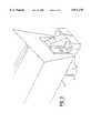
- FIG. 1is a perspective view of a preferred embodiment of the redundant front suspension system in accordance with the invention, the drawing showing a portion of the aircraft pylon to which the system is attached but not showing any of the turboshaft engine for the sake of clarity.
- FIG. 2is a perspective view of the primary suspension device of the system shown in FIG. 1, including the thrust take-up rods.
- FIG. 3shows part of the aircraft pylon and its heel on which the suspension system is mounted.
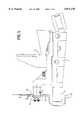
- FIG. 4is a perspective view of the emergency suspension device of the suspension system.
- FIG. 5is a side view of the assembled suspension system.
- FIG. 6is an enlarged view, partly in section, of a part of the emergency suspension device.
- FIG. 1shows a redundant front suspension system 1 for mounting a turboshaft engine on the pylon 2 of an aircraft.
- the engineis not shown for the sake of clarity, but it is sufficient to know that the front suspension point of the engine is located on the intermediate casing thereof.
- the pylon 2is fitted with a heel 3 to which the suspension system 1 is secured as is shown in FIGS. 1 and 5.
- the suspension system 1includes a primary suspension device which forms the normal front suspension of the turboshaft engine and which comprises a base support 4 as shown in FIGS. 1, 2 and 5.
- the base support 4is usually fixed under the heel 3, and extends towards the front of the aircraft in the direction of flight.
- the base support 4has a support shaft 5 which extends forwardly in the direction of the longitudinal axis X of the aircraft reference trihedron and which constitutes the forward suspension shaft for the engine.
- the shaft 5serves to take up the forces acting along the vertical axis Z and the transverse axis Y of the reference trihedron, these forces resulting from the weight of the engine, and from the dynamic forces due to vertical and lateral accelerations caused by vertical and lateral movements of the aircraft.
- thrust take-up rods 6, 7which extend forwardly at an angle to the longitudinal axis X and have their front ends secured laterally to the intermediate casing of the engine. These rods 6, 7 transmit the forces produced by the engine thrust, which acts in the direction of longitudinal axis X of the reference trihedron .
- the front suspension system 1includes an emergency suspension device 10 which operates only in the event of a failure of the normal suspension.
- the emergency device 10is in the form of a unitary member interposed between the under side of the heel 3 and the top surface of the base support 4 and having a vertical abutment 11 at its front end from which a shaft 12 extends parallel to the longitudinal axis X at a position above the shaft 5.
- This additional member 10is formed with a plurality of holes for the passage of fixing bolts for re-establishing the interface between the pylon 2 and the base support 4.
- FIGS. 5 and 6the shaft 12 is received, with clearance, in an appropriate bore provided in the intermediate casing 13 of the engine, and means is provided to enable the shaft 12 to take up the X-axis forces in the event of either of the thrust take-up rods 6, 7 rupturing.
- FIG. 5shows an example of such means wherein an abutment 14 is fixed to the end of the shaft 12 and a cover plate 15 is secured to the casing 13 around the shaft 12.
- a clearance J1is allowed between the shaft 12 and the cover plate 15 and a clearance J2 is allowed between the abutment 14 and the cover plate 15 so that the emergency device remains free from loads in normal operation.
Landscapes
- Engineering & Computer Science (AREA)
- Aviation & Aerospace Engineering (AREA)
- Structures Of Non-Positive Displacement Pumps (AREA)
- Vibration Prevention Devices (AREA)
Abstract
Description
Claims (3)
Applications Claiming Priority (2)
| Application Number | Priority Date | Filing Date | Title |
|---|---|---|---|
| FR9614190 | 1996-11-21 | ||
| FR9614190AFR2755943B1 (en) | 1996-11-21 | 1996-11-21 | REDUNDANT FRONT SUSPENSION FOR TURBOMACHINE |
Publications (1)
| Publication Number | Publication Date |
|---|---|
| US5871176Atrue US5871176A (en) | 1999-02-16 |
Family
ID=9497843
Family Applications (1)
| Application Number | Title | Priority Date | Filing Date |
|---|---|---|---|
| US08/974,559Expired - LifetimeUS5871176A (en) | 1996-11-21 | 1997-11-19 | Redundant front suspension system for a turboshaft engine |
Country Status (4)
| Country | Link |
|---|---|
| US (1) | US5871176A (en) |
| EP (1) | EP0844172B1 (en) |
| DE (1) | DE69720918T2 (en) |
| FR (1) | FR2755943B1 (en) |
Cited By (28)
| Publication number | Priority date | Publication date | Assignee | Title |
|---|---|---|---|---|
| EP1103463A1 (en)* | 1999-11-20 | 2001-05-30 | ROLLS-ROYCE plc | A gas turbine engine mounting arrangement |
| US20040094680A1 (en)* | 2000-12-21 | 2004-05-20 | Francois Brefort | Suspension part of a turbojet engine |
| US20040245383A1 (en)* | 2001-05-19 | 2004-12-09 | Udall Kenneth F. | Mounting arrangement for a gas turbine engine |
| WO2006097484A1 (en)* | 2005-03-18 | 2006-09-21 | Airbus France | Engine fastener of a mounting system interposed between an attachment strut and an aircraft engine |
| EP1712466A1 (en)* | 2005-04-16 | 2006-10-18 | Rolls-Royce plc | Gas turbine engine mounting arrangement |
| US20090056343A1 (en)* | 2007-08-01 | 2009-03-05 | Suciu Gabriel L | Engine mounting configuration for a turbofan gas turbine engine |
| US20090183512A1 (en)* | 2008-01-18 | 2009-07-23 | Suciu Gabriel L | Mounting system for a gas turbine engine |
| US20090218441A1 (en)* | 2005-10-31 | 2009-09-03 | Herve Marche | Device for Fastening A Turbojet Engine to an Aircraft Fixing Strut |
| US20090236469A1 (en)* | 2008-03-21 | 2009-09-24 | Suciu Gabriel L | Mounting system for a gas turbine engine |
| US20090308972A1 (en)* | 2008-06-11 | 2009-12-17 | Rolls-Royce Plc | Engine mounting apparatus |
| US20090308078A1 (en)* | 2008-06-11 | 2009-12-17 | Rolls-Royce Plc | Engine mounting apparatus |
| US20090314881A1 (en)* | 2008-06-02 | 2009-12-24 | Suciu Gabriel L | Engine mount system for a turbofan gas turbine engine |
| US20100181418A1 (en)* | 2007-06-22 | 2010-07-22 | Aircelle | Securing plate and longitudinal handling member for a one-piece aircraft propulsion unit |
| US8448895B2 (en) | 2008-06-02 | 2013-05-28 | United Technologies Corporation | Gas turbine engine compressor arrangement |
| US8511605B2 (en) | 2008-06-02 | 2013-08-20 | United Technologies Corporation | Gas turbine engine with low stage count low pressure turbine |
| US8511604B2 (en) | 2008-06-02 | 2013-08-20 | United Technologies Corporation | Gas turbine engine with low stage count low pressure turbine |
| WO2014036554A1 (en) | 2012-08-31 | 2014-03-06 | United Technologies Corporation | Assembly for mounting a turbine engine to a pylon |
| US8695920B2 (en) | 2008-06-02 | 2014-04-15 | United Technologies Corporation | Gas turbine engine with low stage count low pressure turbine |
| US8844265B2 (en) | 2007-08-01 | 2014-09-30 | United Technologies Corporation | Turbine section of high bypass turbofan |
| US20150298815A1 (en)* | 2012-11-02 | 2015-10-22 | United Technologies Corporation | Redundant mount system |
| US20150336678A1 (en)* | 2014-05-26 | 2015-11-26 | Airbus Operations (Sas) | Engine fastener for an aircraft |
| US10060357B2 (en) | 2007-08-01 | 2018-08-28 | United Technologies Corporation | Turbine section of high bypass turbofan |
| US10451004B2 (en) | 2008-06-02 | 2019-10-22 | United Technologies Corporation | Gas turbine engine with low stage count low pressure turbine |
| US10823052B2 (en) | 2013-10-16 | 2020-11-03 | Raytheon Technologies Corporation | Geared turbofan engine with targeted modular efficiency |
| US11149650B2 (en) | 2007-08-01 | 2021-10-19 | Raytheon Technologies Corporation | Turbine section of high bypass turbofan |
| US11242805B2 (en) | 2007-08-01 | 2022-02-08 | Raytheon Technologies Corporation | Turbine section of high bypass turbofan |
| US11346289B2 (en) | 2007-08-01 | 2022-05-31 | Raytheon Technologies Corporation | Turbine section of high bypass turbofan |
| US11486311B2 (en) | 2007-08-01 | 2022-11-01 | Raytheon Technologies Corporation | Turbine section of high bypass turbofan |
Families Citing this family (5)
| Publication number | Priority date | Publication date | Assignee | Title |
|---|---|---|---|---|
| FR2793769B1 (en)* | 1999-05-19 | 2001-09-07 | Aerospatiale Airbus | DEVICE FOR HANGING AN AIRCRAFT ENGINE TO A MAT |
| FR2799432A1 (en)* | 1999-10-07 | 2001-04-13 | Snecma | SUSPENSION WITH INTEGRATED SAFETY FOR AIRCRAFT PUMP GROUPS |
| FR2891243B1 (en)* | 2005-09-26 | 2009-04-03 | Airbus France Sas | ENGINE ATTACHING MAT FOR AN AIRCRAFT |
| FR2891245B1 (en)* | 2005-09-26 | 2007-10-26 | Airbus France Sas | METHOD FOR MOUNTING AN AIRCRAFT ENGINE ON A RIGID STRUCTURE OF A MOTOR ATTACHMENT MAT |
| FR3021299B1 (en)* | 2014-05-26 | 2016-07-01 | Airbus Operations Sas | ENGINE ATTACHMENT FOR AN AIRCRAFT |
Citations (8)
| Publication number | Priority date | Publication date | Assignee | Title |
|---|---|---|---|---|
| FR2217549A1 (en)* | 1973-02-14 | 1974-09-06 | Gen Electric | |
| US3907220A (en)* | 1974-03-14 | 1975-09-23 | United Aircraft Corp | Rear engine redundant mount |
| US4065077A (en)* | 1976-04-30 | 1977-12-27 | Rolls-Royce Limited | Attachment for attaching jet propulsion engines to fixed structure |
| US4560122A (en)* | 1983-01-12 | 1985-12-24 | British Aerospace Public Limited Company | Power plant attachment arrangements for aircraft wings |
| FR2599708A1 (en)* | 1986-06-10 | 1987-12-11 | Snecma | DEVICE FOR REARLY SECURING A TURBOJET ENGINE ON AN AIRCRAFT MAT |
| FR2680353A1 (en)* | 1991-08-14 | 1993-02-19 | Snecma | REAR HANGING STRUCTURE OF A TURBOREACTOR. |
| WO1993011041A1 (en)* | 1991-11-25 | 1993-06-10 | Rolls-Royce Plc | A mounting arrangement for a gas turbine engine |
| US5303880A (en)* | 1992-10-28 | 1994-04-19 | General Electric Company | Aircraft engine pin mount |
- 1996
- 1996-11-21FRFR9614190Apatent/FR2755943B1/ennot_activeExpired - Fee Related
- 1997
- 1997-11-19USUS08/974,559patent/US5871176A/ennot_activeExpired - Lifetime
- 1997-11-20DEDE69720918Tpatent/DE69720918T2/ennot_activeExpired - Lifetime
- 1997-11-20EPEP97402788Apatent/EP0844172B1/ennot_activeExpired - Lifetime
Patent Citations (9)
| Publication number | Priority date | Publication date | Assignee | Title |
|---|---|---|---|---|
| FR2217549A1 (en)* | 1973-02-14 | 1974-09-06 | Gen Electric | |
| US3907220A (en)* | 1974-03-14 | 1975-09-23 | United Aircraft Corp | Rear engine redundant mount |
| US4065077A (en)* | 1976-04-30 | 1977-12-27 | Rolls-Royce Limited | Attachment for attaching jet propulsion engines to fixed structure |
| US4560122A (en)* | 1983-01-12 | 1985-12-24 | British Aerospace Public Limited Company | Power plant attachment arrangements for aircraft wings |
| FR2599708A1 (en)* | 1986-06-10 | 1987-12-11 | Snecma | DEVICE FOR REARLY SECURING A TURBOJET ENGINE ON AN AIRCRAFT MAT |
| FR2680353A1 (en)* | 1991-08-14 | 1993-02-19 | Snecma | REAR HANGING STRUCTURE OF A TURBOREACTOR. |
| WO1993011041A1 (en)* | 1991-11-25 | 1993-06-10 | Rolls-Royce Plc | A mounting arrangement for a gas turbine engine |
| US5474258A (en)* | 1991-11-25 | 1995-12-12 | Rolls-Royce Plc | Mounting arrangement for a gas turbine engine |
| US5303880A (en)* | 1992-10-28 | 1994-04-19 | General Electric Company | Aircraft engine pin mount |
Cited By (67)
| Publication number | Priority date | Publication date | Assignee | Title |
|---|---|---|---|---|
| EP1103463A1 (en)* | 1999-11-20 | 2001-05-30 | ROLLS-ROYCE plc | A gas turbine engine mounting arrangement |
| US6474597B1 (en) | 1999-11-20 | 2002-11-05 | Rolls-Royce Plc | Gas turbine engine mounting arrangement |
| US20040094680A1 (en)* | 2000-12-21 | 2004-05-20 | Francois Brefort | Suspension part of a turbojet engine |
| US6986482B2 (en)* | 2000-12-21 | 2006-01-17 | Snecma Moteurs | Suspension part of a turbojet engine |
| US20040245383A1 (en)* | 2001-05-19 | 2004-12-09 | Udall Kenneth F. | Mounting arrangement for a gas turbine engine |
| US6935591B2 (en)* | 2001-05-19 | 2005-08-30 | Rolls-Royce Plc | Mounting arrangement for a gas turbine engine |
| US20080169378A1 (en)* | 2005-03-18 | 2008-07-17 | Airbus France | Engine Fastener Of A Mounting System Interposed Between An Attachment Strut And An Aircraft Engine |
| WO2006097484A1 (en)* | 2005-03-18 | 2006-09-21 | Airbus France | Engine fastener of a mounting system interposed between an attachment strut and an aircraft engine |
| JP4941999B2 (en)* | 2005-03-18 | 2012-05-30 | エアバス オペレーションズ (エスアーエス) | Mounting system engine fasteners interposed between mounting struts and aircraft engines |
| US8336812B2 (en) | 2005-03-18 | 2012-12-25 | Airbus Operations Sas | Engine attachment for an assembly system mounted between an attachment strut and an aircraft engine |
| RU2387583C2 (en)* | 2005-03-18 | 2010-04-27 | Эрбюс Франс | Engine suspension assembly in mounting system installed between mounting pillar and engine of aircraft |
| JP2008532846A (en)* | 2005-03-18 | 2008-08-21 | エアバス・フランス | Mounting system engine fasteners interposed between mounting struts and aircraft engines |
| FR2883256A1 (en)* | 2005-03-18 | 2006-09-22 | Airbus France Sas | ENGINE ATTACHMENT OF A MOUNTING SYSTEM INTERPOSED BETWEEN A COUPLING MACHINE AND AN AIRCRAFT ENGINE |
| US7438262B2 (en)* | 2005-04-16 | 2008-10-21 | Rolls-Royce Plc. | Redundant gas turbine engine mounting arrangement |
| US20060231679A1 (en)* | 2005-04-16 | 2006-10-19 | Rolls-Royce Plc | Gas turbine engine mounting arrangement |
| EP1712466A1 (en)* | 2005-04-16 | 2006-10-18 | Rolls-Royce plc | Gas turbine engine mounting arrangement |
| US8366038B2 (en)* | 2005-10-31 | 2013-02-05 | Airbus Operations Sas | Device for fastening a turbojet engine to an aircraft fixing strut |
| US20090218441A1 (en)* | 2005-10-31 | 2009-09-03 | Herve Marche | Device for Fastening A Turbojet Engine to an Aircraft Fixing Strut |
| US9156566B2 (en)* | 2007-06-22 | 2015-10-13 | Aircelle | Securing plate and longitudinal handling member for a one-piece aircraft propulsion unit |
| US20100181418A1 (en)* | 2007-06-22 | 2010-07-22 | Aircelle | Securing plate and longitudinal handling member for a one-piece aircraft propulsion unit |
| US11486311B2 (en) | 2007-08-01 | 2022-11-01 | Raytheon Technologies Corporation | Turbine section of high bypass turbofan |
| US11614036B2 (en) | 2007-08-01 | 2023-03-28 | Raytheon Technologies Corporation | Turbine section of gas turbine engine |
| US8850793B2 (en) | 2007-08-01 | 2014-10-07 | United Technologies Corporation | Turbine section of high bypass turbofan |
| US11346289B2 (en) | 2007-08-01 | 2022-05-31 | Raytheon Technologies Corporation | Turbine section of high bypass turbofan |
| US11242805B2 (en) | 2007-08-01 | 2022-02-08 | Raytheon Technologies Corporation | Turbine section of high bypass turbofan |
| US11215123B2 (en) | 2007-08-01 | 2022-01-04 | Raytheon Technologies Corporation | Turbine section of high bypass turbofan |
| US8844265B2 (en) | 2007-08-01 | 2014-09-30 | United Technologies Corporation | Turbine section of high bypass turbofan |
| US8256707B2 (en)* | 2007-08-01 | 2012-09-04 | United Technologies Corporation | Engine mounting configuration for a turbofan gas turbine engine |
| US11149650B2 (en) | 2007-08-01 | 2021-10-19 | Raytheon Technologies Corporation | Turbine section of high bypass turbofan |
| US11480108B2 (en) | 2007-08-01 | 2022-10-25 | Raytheon Technologies Corporation | Turbine section of high bypass turbofan |
| US9010085B2 (en) | 2007-08-01 | 2015-04-21 | United Technologies Corporation | Turbine section of high bypass turbofan |
| US10794293B2 (en) | 2007-08-01 | 2020-10-06 | Raytheon Technologies Corporation | Turbine section of high bypass turbofan |
| US10662880B2 (en) | 2007-08-01 | 2020-05-26 | Raytheon Technologies Corporation | Turbine section of high bypass turbofan |
| US10371061B2 (en) | 2007-08-01 | 2019-08-06 | United Technologies Corporation | Turbine section of high bypass turbofan |
| US10060357B2 (en) | 2007-08-01 | 2018-08-28 | United Technologies Corporation | Turbine section of high bypass turbofan |
| US20090056343A1 (en)* | 2007-08-01 | 2009-03-05 | Suciu Gabriel L | Engine mounting configuration for a turbofan gas turbine engine |
| US20090183512A1 (en)* | 2008-01-18 | 2009-07-23 | Suciu Gabriel L | Mounting system for a gas turbine engine |
| US8118251B2 (en) | 2008-01-18 | 2012-02-21 | United Technologies Corporation | Mounting system for a gas turbine engine |
| US20090236469A1 (en)* | 2008-03-21 | 2009-09-24 | Suciu Gabriel L | Mounting system for a gas turbine engine |
| US8328133B2 (en) | 2008-03-21 | 2012-12-11 | United Technologies Corporation | Mounting system for a gas turbine engine |
| US8167237B2 (en) | 2008-03-21 | 2012-05-01 | United Technologies Corporation | Mounting system for a gas turbine engine |
| US11731773B2 (en) | 2008-06-02 | 2023-08-22 | Raytheon Technologies Corporation | Engine mount system for a gas turbine engine |
| US10451004B2 (en) | 2008-06-02 | 2019-10-22 | United Technologies Corporation | Gas turbine engine with low stage count low pressure turbine |
| US12179929B2 (en) | 2008-06-02 | 2024-12-31 | Rtx Corporation | Engine mount system for a gas turbine engine |
| US20090314881A1 (en)* | 2008-06-02 | 2009-12-24 | Suciu Gabriel L | Engine mount system for a turbofan gas turbine engine |
| US8128021B2 (en) | 2008-06-02 | 2012-03-06 | United Technologies Corporation | Engine mount system for a turbofan gas turbine engine |
| US8807477B2 (en) | 2008-06-02 | 2014-08-19 | United Technologies Corporation | Gas turbine engine compressor arrangement |
| US11286883B2 (en) | 2008-06-02 | 2022-03-29 | Raytheon Technologies Corporation | Gas turbine engine with low stage count low pressure turbine and engine mounting arrangement |
| US8511604B2 (en) | 2008-06-02 | 2013-08-20 | United Technologies Corporation | Gas turbine engine with low stage count low pressure turbine |
| US8511605B2 (en) | 2008-06-02 | 2013-08-20 | United Technologies Corporation | Gas turbine engine with low stage count low pressure turbine |
| US8800914B2 (en) | 2008-06-02 | 2014-08-12 | United Technologies Corporation | Gas turbine engine with low stage count low pressure turbine |
| US8448895B2 (en) | 2008-06-02 | 2013-05-28 | United Technologies Corporation | Gas turbine engine compressor arrangement |
| US8695920B2 (en) | 2008-06-02 | 2014-04-15 | United Technologies Corporation | Gas turbine engine with low stage count low pressure turbine |
| US20090308078A1 (en)* | 2008-06-11 | 2009-12-17 | Rolls-Royce Plc | Engine mounting apparatus |
| US8443612B2 (en) | 2008-06-11 | 2013-05-21 | Rolls-Royce Plc | Engine mounting arrangement |
| US8152094B2 (en)* | 2008-06-11 | 2012-04-10 | Rolls-Royce Plc | Engine mounting apparatus |
| US20090308972A1 (en)* | 2008-06-11 | 2009-12-17 | Rolls-Royce Plc | Engine mounting apparatus |
| WO2014036554A1 (en) | 2012-08-31 | 2014-03-06 | United Technologies Corporation | Assembly for mounting a turbine engine to a pylon |
| EP2893172A4 (en)* | 2012-08-31 | 2016-06-01 | United Technologies Corp | Assembly for mounting a turbine engine to a pylon |
| US9469412B2 (en)* | 2012-11-02 | 2016-10-18 | United Technologies Corporation | Redundant mount system |
| US20150298815A1 (en)* | 2012-11-02 | 2015-10-22 | United Technologies Corporation | Redundant mount system |
| US11371427B2 (en) | 2013-10-16 | 2022-06-28 | Raytheon Technologies Corporation | Geared turbofan engine with targeted modular efficiency |
| US10823052B2 (en) | 2013-10-16 | 2020-11-03 | Raytheon Technologies Corporation | Geared turbofan engine with targeted modular efficiency |
| US11585268B2 (en) | 2013-10-16 | 2023-02-21 | Raytheon Technologies Corporation | Geared turbofan engine with targeted modular efficiency |
| US11859538B2 (en) | 2013-10-16 | 2024-01-02 | Rtx Corporation | Geared turbofan engine with targeted modular efficiency |
| US9573694B2 (en)* | 2014-05-26 | 2017-02-21 | Airbus Operations Sas | Engine fastener for an aircraft |
| US20150336678A1 (en)* | 2014-05-26 | 2015-11-26 | Airbus Operations (Sas) | Engine fastener for an aircraft |
Also Published As
| Publication number | Publication date |
|---|---|
| DE69720918D1 (en) | 2003-05-22 |
| FR2755943A1 (en) | 1998-05-22 |
| FR2755943B1 (en) | 1998-12-24 |
| EP0844172B1 (en) | 2003-04-16 |
| DE69720918T2 (en) | 2004-02-26 |
| EP0844172A1 (en) | 1998-05-27 |
Similar Documents
| Publication | Publication Date | Title |
|---|---|---|
| US5871176A (en) | Redundant front suspension system for a turboshaft engine | |
| US5871175A (en) | Redundant front suspension system for a turboshaft engine | |
| US5871177A (en) | Redundant front suspension system for a turboshaft engine | |
| US7566029B2 (en) | Suspension for suspending a jet engine on an aircraft strut | |
| US7909302B2 (en) | Two-shackle aircraft engine attachment | |
| US8256708B2 (en) | Device for attaching an aircraft engine comprising a thrust force take-up device with a compact design | |
| US6682015B2 (en) | Device for the attachment of an engine to an aircraft | |
| US8727268B2 (en) | Attachment device for aircraft engine and aircraft comprising at least one such device | |
| US5238206A (en) | Rear hanging structure for a turbojet engine | |
| US6474597B1 (en) | Gas turbine engine mounting arrangement | |
| US6347765B1 (en) | Device for attaching an aircraft engine to a strut | |
| RU2468963C2 (en) | Fan body support frame mounted at nacelle attachment pylon and air intake | |
| US8167238B2 (en) | Pylon caisson attachment on a wing, gripping a lateral panel of the caisson | |
| US8251311B2 (en) | Attachment pylon for aircraft having a rear engine attachment beam offset from the caisson | |
| RU2398713C2 (en) | Aircraft device comprising wing and suspension pylon | |
| US8205826B2 (en) | Device for attaching an aircraft engine and aircraft comprising at least one such device | |
| US11338929B2 (en) | Forward engine attachment system for an aircraft engine comprising a direct coupling between the jet engine pylon and the engine | |
| US11975856B2 (en) | Front engine attachment system for an aircraft engine, comprising a more a lightweight structure | |
| CA2624017A1 (en) | Aircraft engine assembly | |
| US11027852B2 (en) | Assembly for aircraft comprising a primary mounting pylon structure fixed to an airfoil box using a bolted link | |
| US11572184B2 (en) | Front engine attachment system for an aircraft engine, having rod systems with two rods | |
| US5154371A (en) | Main rotor assembly support truss | |
| US20230030853A1 (en) | Aircraft propulsion assembly having a jet engine, a pylon and means for attaching the jet engine to the pylon | |
| US8308105B2 (en) | Aircraft engine pylon attachment | |
| US20200369396A1 (en) | Rear engine attachment system for an aircraft engine, having a beam made in three parts |
Legal Events
| Date | Code | Title | Description |
|---|---|---|---|
| AS | Assignment | Owner name:SOCIETE NATIONALE D'ETUDE ET DE CONSTRUCTION DE MO Free format text:ASSIGNMENT OF ASSIGNORS INTEREST;ASSIGNORS:DEMOUZON, FRANCIS MICHEL;FER, RENE PIERRE;HUET, PATRICK JEAN ALIBERT;AND OTHERS;REEL/FRAME:009588/0475 Effective date:19971107 | |
| STCF | Information on status: patent grant | Free format text:PATENTED CASE | |
| FPAY | Fee payment | Year of fee payment:4 | |
| AS | Assignment | Owner name:SNECMA MOTEURS, FRANCE Free format text:CHANGE OF NAME;ASSIGNOR:SOCIETE NATIONALE D'ETUDES ET DE CONSTRUCTION DE MOTEURS D'AVIATION;REEL/FRAME:014754/0192 Effective date:20000117 | |
| FPAY | Fee payment | Year of fee payment:8 | |
| AS | Assignment | Owner name:SNECMA, FRANCE Free format text:CHANGE OF NAME;ASSIGNOR:SNECMA MOTEURS;REEL/FRAME:020609/0569 Effective date:20050512 Owner name:SNECMA,FRANCE Free format text:CHANGE OF NAME;ASSIGNOR:SNECMA MOTEURS;REEL/FRAME:020609/0569 Effective date:20050512 | |
| FEPP | Fee payment procedure | Free format text:PAYER NUMBER DE-ASSIGNED (ORIGINAL EVENT CODE: RMPN); ENTITY STATUS OF PATENT OWNER: LARGE ENTITY Free format text:PAYOR NUMBER ASSIGNED (ORIGINAL EVENT CODE: ASPN); ENTITY STATUS OF PATENT OWNER: LARGE ENTITY | |
| FPAY | Fee payment | Year of fee payment:12 | |
| AS | Assignment | Owner name:SAFRAN AIRCRAFT ENGINES, FRANCE Free format text:CHANGE OF NAME;ASSIGNOR:SNECMA;REEL/FRAME:046479/0807 Effective date:20160803 | |
| AS | Assignment | Owner name:SAFRAN AIRCRAFT ENGINES, FRANCE Free format text:CORRECTIVE ASSIGNMENT TO CORRECT THE COVER SHEET TO REMOVE APPLICATION NOS. 10250419, 10786507, 10786409, 12416418, 12531115, 12996294, 12094637 12416422 PREVIOUSLY RECORDED ON REEL 046479 FRAME 0807. ASSIGNOR(S) HEREBY CONFIRMS THE CHANGE OF NAME;ASSIGNOR:SNECMA;REEL/FRAME:046939/0336 Effective date:20160803 |