US5870881A - Box closing apparatus - Google Patents
Box closing apparatusDownload PDFInfo
- Publication number
- US5870881A US5870881AUS08/883,893US88389397AUS5870881AUS 5870881 AUS5870881 AUS 5870881AUS 88389397 AUS88389397 AUS 88389397AUS 5870881 AUS5870881 AUS 5870881A
- Authority
- US
- United States
- Prior art keywords
- press plate
- lower press
- plate means
- box
- pin
- Prior art date
- Legal status (The legal status is an assumption and is not a legal conclusion. Google has not performed a legal analysis and makes no representation as to the accuracy of the status listed.)
- Expired - Fee Related
Links
- 239000004065semiconductorSubstances0.000claimsdescription20
- 239000002245particleSubstances0.000claimsdescription7
- 238000007789sealingMethods0.000claimsdescription4
- 230000000284resting effectEffects0.000claimsdescription3
- 235000012431wafersNutrition0.000description28
- 238000010276constructionMethods0.000description5
- 239000000463materialSubstances0.000description4
- 238000004806packaging method and processMethods0.000description3
- 238000007790scrapingMethods0.000description3
- XAGFODPZIPBFFR-UHFFFAOYSA-NaluminiumChemical compound[Al]XAGFODPZIPBFFR-UHFFFAOYSA-N0.000description2
- 229910052782aluminiumInorganic materials0.000description2
- 230000004888barrier functionEffects0.000description2
- 229910001220stainless steelInorganic materials0.000description2
- 239000010935stainless steelSubstances0.000description2
- 230000004913activationEffects0.000description1
- 238000007796conventional methodMethods0.000description1
- 230000000881depressing effectEffects0.000description1
- 230000000994depressogenic effectEffects0.000description1
- 235000000396ironNutrition0.000description1
- 238000004519manufacturing processMethods0.000description1
- 238000012858packaging processMethods0.000description1
- 239000013618particulate matterSubstances0.000description1
- 239000002861polymer materialSubstances0.000description1
- 238000003466weldingMethods0.000description1
Images


Classifications
- H—ELECTRICITY
- H01—ELECTRIC ELEMENTS
- H01L—SEMICONDUCTOR DEVICES NOT COVERED BY CLASS H10
- H01L21/00—Processes or apparatus adapted for the manufacture or treatment of semiconductor or solid state devices or of parts thereof
- H01L21/67—Apparatus specially adapted for handling semiconductor or electric solid state devices during manufacture or treatment thereof; Apparatus specially adapted for handling wafers during manufacture or treatment of semiconductor or electric solid state devices or components ; Apparatus not specifically provided for elsewhere
- H01L21/673—Apparatus specially adapted for handling semiconductor or electric solid state devices during manufacture or treatment thereof; Apparatus specially adapted for handling wafers during manufacture or treatment of semiconductor or electric solid state devices or components ; Apparatus not specifically provided for elsewhere using specially adapted carriers or holders; Fixing the workpieces on such carriers or holders
- H01L21/6735—Closed carriers
- H01L21/67373—Closed carriers characterised by locking systems
- B—PERFORMING OPERATIONS; TRANSPORTING
- B65—CONVEYING; PACKING; STORING; HANDLING THIN OR FILAMENTARY MATERIAL
- B65B—MACHINES, APPARATUS OR DEVICES FOR, OR METHODS OF, PACKAGING ARTICLES OR MATERIALS; UNPACKING
- B65B7/00—Closing containers or receptacles after filling
- B65B7/16—Closing semi-rigid or rigid containers or receptacles not deformed by, or not taking-up shape of, contents, e.g. boxes or cartons
- B65B7/28—Closing semi-rigid or rigid containers or receptacles not deformed by, or not taking-up shape of, contents, e.g. boxes or cartons by applying separate preformed closures, e.g. lids, covers
- B65B7/2842—Securing closures on containers
- B65B7/2864—Securing closures on containers by adhesive tape
Definitions
- This inventionrelates generally to packaging of semiconductor wafers, and more particularly to a box closing apparatus for semiconductor wafer packaging.
- the final stages of semiconductor wafer productionare conventionally carried out in a clean room so that the finished wafers are free from particulate matter deposits and moisture.
- the condition of the wafersmust be maintained as they are transported to a facility in another city or country. Moreover, the wafers must not be physically damaged either by the packaging process or by the rigors of their transportation.
- these boxestypically contain a cassette which holds the wafers with minimal contact of the front and rear surfaces of the wafer.
- the wafersmay be loaded into the cassette manually, or automatically by existing machinery.
- the loaded cassettesare manually placed in a lower portion of the box.
- An upper portion of the boxis placed on the lower portion over the cassette and pressed down against the lower portion.
- the boxis designed for a snap-latching interengagement of the upper and lower halves.
- tapeis applied around the circumference of the box over the joint between the upper and lower halves.
- the boxis then sealed inside a flexible, moisture barrier package (e.g., an aluminum coated acrylar polymer material).
- the provision of apparatus for closing a semiconductor wafer boxwhich assures a sealing closure of the box; the provision of such apparatus which closes all transport boxes in a uniform manner; the provision of such apparatus which facilitates rapid packaging of the wafers; the provision of such apparatus which facilitates taping to seal a joint on the box; the provision of such apparatus which permits accurate location of the box in the apparatus; and the provision of such apparatus which is easy to use.
- a box closing apparatus of the present inventioncloses a box having an upper portion and a lower portion constructed for snap-latching interconnection with each other.
- the apparatuscomprises lower press plate means constructed for supporting the transport box thereon, and upper press plate means mounted above and in generally opposed relation with the lower press plate means.
- Actuator meansactuates relative movement of the upper and lower press plates means between an open position and a closing position. In the open position the upper and lower press plate means are spaced apart for placement of the box on the lower press plate means with the upper portion of the box resting on but unconnected to the lower portion and space between the upper portion of the box and the upper press plate means.
- the actuator meansis constructed for relative movement of the upper and lower plate means a distance from the open position to the closing position selected to bring the upper press plate means into engagement with the upper portion of the box and to compress the upper and lower portions into snap-latching interconnection.
- the upper press plate meansapplies a downward force on the upper portion of the box which is equal in magnitude to the upward force applied to the lower portion of the box by the lower press plate means.
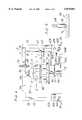
- FIG. 1is a perspective view of apparatus for closing a semiconductor transport box of the present invention
- FIG. 2is an exploded perspective view of the apparatus
- FIG. 3is a front elevational view of the apparatus holding a semiconductor wafer transport box prior to closure of the box;
- FIG. 4is the front elevational view of FIG. 3, but showing the apparatus closing the semiconductor wafer transport box;
- FIG. 5is an enlarged fragmentary cross sectional view of the apparatus showing a portion of an upper press plate and a pin received in the plate.
- apparatus constructed according to the principles of the present inventionis indicated generally at 10.
- the apparatusis constructed for closing a semiconductor wafer transport box generally indicated at 12 (FIGS. 3 and 4).
- FIG. 3 and 4semiconductor wafer transport box
- the present inventionis particularly useful in the context of semiconductor wafer transport boxes, it is envisioned that other types of snap-latching boxes could also be closed with the apparatus of the present invention.
- the transport boxincludes an upper portion 14 which is separable from a lower portion 16 of the box.
- the upper and lower portionsare constructed for snap-latching interconnection.
- the apparatus 10is constructed to operate with existing transport boxes, such as the ULTRAPAK transport box, manufactured by Empak, Inc. of Colorado Springs, Colo.
- the apparatusincludes a base 18 and a frame 20 mounted on the base.
- the frame 20comprises a pair of upright posts 22 and a cross bar 24 extending above the base 18 between the posts.
- the frame 20is attached, as by welding, to the base 18. The attachment is facilitated by angle irons 26 (FIG. 2).
- the base 18is preferably made of aluminum or stainless steel and the frame 20 is preferably made of stainless or non-stainless steel. Other materials may be used, so long as particle generation from the collective materials is kept down to a level acceptable for operation of the apparatus in a clean room.
- the apparatus 10further includes a lower press plate and an upper press plate (generally indicated by reference numerals 30 and 32, respectively). It is to be understood that the lower and upper press plates 30, 32 (broadly, “lower and upper press plate means”) may have other constructions than depicted in the drawings. For instance, either or both of the press plates 30, 32 may not be of unitary construction.
- the lower press plate 30is mounted on the base 18 by an air cylinder 34 (broadly, "actuator means").
- the actuator meansmay be other than an air cylinder and still fall within the scope of the present invention.
- a an electrical actuatorsuch as a solenoid might be used.
- the lower press plate 30is attached to a bearing 36 which is mounted on an arm 38 of the air cylinder 34 (see FIG. 2).
- the air cylinderis operated by push buttons (designated by reference numerals 40A-40D) located on control boxes (designated 42A and 42B, respectively) mounted adjacent respective posts 22 of the frame 20. Simultaneous depression of the upper two buttons 40A, 40B on the two control boxes 42A, 42B causes the cylinder 34 to raise the lower press plate 30.
- a pneumatic circuit for the air cylinder 34is not shown (being of a construction readily understood by those of ordinary skill in the art), but includes tubing 44A leading from the control box 42B to a manifold connector 44B and tubing 44C, 44D leading from the manifold connector to the air cylinder.
- the bearing 36permits the lower press plate 30 to rotate about a vertical axis A relative to the air cylinder 34 and base 18.
- the lower press plate 30comprises a base plate 48 and a pair of spaced-apart, rectangular pads 50 mounted on the base plate and extending along opposite lateral edges of the base plate.
- the pads 50are made of a rigid material in the preferred embodiment.
- the upper press plate 32is supported from the cross bar 24 of the frame 20 above and in a generally opposed relation with the lower press plate 30. More specifically, the upper press plate 32 is attached to a circular connector plate 52 which is mounted on a bearing 54. A shaft 56 extending from the bearing 54 is fixedly mounted on the underside of the cross bar 24, such that the upper press plate 32 is free to rotate relative to the cross bar about substantially the same vertical axis A as the lower press plate 30.
- the upper press plate 32also includes a base plate 58 and a pair of spaced-apart, rectangular pads 60 mounted on the base plate. The pads 60 are made of a rigid material in the preferred embodiment.
- a tape dispenseris mounted on the right post 22 of the frame 20.
- the tape dispenseris capable of holding a roll of tape T (FIGS. 3 and 4) for application to the semiconductor wafer transport box 12.
- the tape dispenser 62includes a bracket 64 attached by a suitable fastener to the post 22, and a spindle 66 on which the roll of tape T is received.
- the roll of tape Tis capable of rotating on the spindle 66 about a vertical axis B to dispense tape from the roll for use in sealing the semiconductor wafer transport box 12, as described more fully hereinafter.
- Means for fixing the lower and upper press plates 30, 32comprises in the preferred embodiment pins (designated at 68 and 70, respectively) which are capable of selective engagement with the lower and upper press plates, respectively, to fix the plates from rotation about the vertical axis A.
- pins 68, 70are illustrated in the preferred embodiment, the fixing means could be other than shown without departing from the scope of the present invention.
- a single membermay be used to lock both plates 30, 32, or the bearings 36, 54 may be locked to prevent rotation.
- the pins 68, 70also precisely locate the lower and upper press plates 30, 32 at the beginning of the operation of the apparatus 10.
- the pin 68 associated with the upper press plate 32is mounted on a bracket 72 attached to the cross bar 24 of the frame 20.
- the pin 68is operable, by actuation of an air cylinder 74, to move to an extended position in which the pin is received in a recess 76 in the upper press plate 32 to fix the upper press plate against rotation about vertical axis A relative to the base 18 and frame 20 (FIG. 5).
- the air cylinder 74is connected by tubing 75 branching off from tubing 44C connecting the air cylinder 34 to the manifold connector 44B.
- Air cylinder 75is operable to raise the pin 68 to a retracted position in which the pin is out of the recess 76 and releases the upper press plate 32 for rotation relative to the base 18 and frame 20.
- the upper end of the pin 68has a bearing 78 on its free end.
- the bearing 78permits the apparatus 10 to function properly even when there is misalignment 68 of the pin with the recess 70. Should misalignment occur, the bearing 78 allows the end of the pin 68 to roll into the recess without scraping against the upper press plate 32. In practice, there will rarely be perfect alignment of the pin 68 with the recess 76 before the cylinder is activated to move the pin into the recess. In the absence of the bearing 78, the pin 68 would scrape against the upper press plate 32 as it moved into the recess, generating particles capable of becoming deposited on the wafers and damaging the apparatus 10.
- the pin 70 associated with the lower press plate 30is mounted on the base 18 and projects up from the base.
- the pin 70is of a fixed length and remains in the same position.
- the reception of the pin 70 in the recess 79is substantially the same as for the pin 68 in the recess 76 of the upper plate 32, as shown in FIG. 5.
- the pin 70has a bearing 80 (FIG. 2) at its free end to permit the pin to slide into the recess 79 without scraping the lower press plate 30.
- FIGS. 3 and 4 of the drawingsFinished semiconductor wafers are loaded into cassettes by conventional techniques and machinery.
- the cassettesare then placed in the lower portion 16 of the semiconductor wafer transport box 12.
- the upper portion 14 of the transport box 12is placed on the lower portion 16 over the cassette, but the upper and lower portions are not interconnected.
- the transport box 12is placed onto the lower press plate 30 of the apparatus 10 as shown in FIG. 3, with a portion of the box known as the H-bar facing outward toward the technician.
- the lateral edge margins of the lower portion 16rest on the pads 50 of the lower press plate 30.
- the lower and upper press plates 30, 32are in an open position in FIG. 3 in which the press plates are spaced apart a distance greater than the height of the transport box 12 so that the box can be easily placed between the press plates. In this position, a joint 84 between the upper and lower portions 14, 16 of the transport box 12 is located slightly below the level of the roll of tape T held by the tape dispenser 62.
- the air cylinder 34extends to raise the lower press plate 30, lifting the semiconductor wafer transport box 12 so that the upper portion 14 of the box engages the upper press plate 32 in a closing position of the apparatus 10. More particularly, the upper portion 14 engages the pads 60 of the upper press plate 32 along opposite lateral sides of the box 12.
- the central portion of the transport box 12, where the wafer are most closely proximate to the outer wall of the box,does not engage the upper press plate 32.
- the upper press plateapplies a reaction force to the upper portion 14 of the transport box 12 which is equal in magnitude and opposite in direction to the force applied by the lower press plate 30 to the lower portion 16 of the transport box.
- the forceis applied uniformly over the parts of the transport box 12 engaging the pads 50, 60.
- the even application of force between the upper and lower portions 14, 16 of the box 12permits the portions to snap together around the full circumference of the box.
- the transport box 12is fully sealed.
- the upper press plateis now free to rotate about the vertical axis A relative to the base 18 and frame 20.
- the air cylinder 34 raises the lower press plate 30the plate moves off of the pin 70 so that the lower press plate is free to rotate about the vertical axis A.
- the clamping action of the lower and upper press plates 30, 32 against the semiconductor wafer transport box 12fixes the lower and upper press plates and the box to move conjointly about the vertical axis A.
- the joint 82 between the upper and lower portions 14, 16is substantially on level with the roll of tape T held by the tape dispenser 62 in the closing position of the apparatus 10.
- the technicianpulls tape from the roll T, as indicated by the phantom lines shown in FIG. 4, and adheres the free end of the tape to the back side of the transport box 12.
- the box(along with the lower and upper press plates 30, 32) is then rotated, causing more tape to be pulled off of the roll T.
- the tapeis pressed against the joint 82 and the transport box 12 is rotated until the entire joint is covered with tape.
- the alignment of the joint 82 with the tape dispenser 62facilitates an symmetric placement of the tape on the upper and lower portions 14, 16 of the transport box 12 all the way around the joint.
- the transport box 12is rotated through about 11/4 turns.
- the tapeis cut from the roll T and some of the excess tape is folded under itself to form a pull tab to facilitate opening the transport box 12 when it reaches its final destination.
- the technicianrotates the taped semiconductor wafer transport box 12 back to its original orientation.
- the lower buttons 40C, 40D on the control boxes 42A, 42Bare simultaneously depressed, causing the air cylinder 34 to lower the lower press plate 30.
- the transport box 12In the open position, the transport box 12 can be slid out from between the lower and upper plates 30, 32 to remove it from the apparatus 10.
- the transport box 12is then placed in a flexible, moisture barrier bag (not shown) before it is ready for delivery.
- Depression of the lower buttons 40C, 40Dalso activates air cylinder 74 to extend the pin 68 into the recess 76 on the upper press plate 32.
- the free end of the pin 68may engage the lower press plate 30 to one side of the opening because of a misalignment of the recess 76 with the pin.
- the bearing 78 on the end of the pin 68will permit the pin to slide into the recess 76 without scraping against the upper press plate 32.
- the bearing 80 on the end of the pin 70facilitates entry of the pin into the recess of the lower plate 30 without particle generation.
Landscapes
- Engineering & Computer Science (AREA)
- Physics & Mathematics (AREA)
- Condensed Matter Physics & Semiconductors (AREA)
- General Physics & Mathematics (AREA)
- Manufacturing & Machinery (AREA)
- Computer Hardware Design (AREA)
- Microelectronics & Electronic Packaging (AREA)
- Power Engineering (AREA)
- Mechanical Engineering (AREA)
- Container, Conveyance, Adherence, Positioning, Of Wafer (AREA)
Abstract
Description
Claims (19)
Priority Applications (1)
| Application Number | Priority Date | Filing Date | Title |
|---|---|---|---|
| US08/883,893US5870881A (en) | 1997-06-27 | 1997-06-27 | Box closing apparatus |
Applications Claiming Priority (1)
| Application Number | Priority Date | Filing Date | Title |
|---|---|---|---|
| US08/883,893US5870881A (en) | 1997-06-27 | 1997-06-27 | Box closing apparatus |
Publications (1)
| Publication Number | Publication Date |
|---|---|
| US5870881Atrue US5870881A (en) | 1999-02-16 |
Family
ID=25383547
Family Applications (1)
| Application Number | Title | Priority Date | Filing Date |
|---|---|---|---|
| US08/883,893Expired - Fee RelatedUS5870881A (en) | 1997-06-27 | 1997-06-27 | Box closing apparatus |
Country Status (1)
| Country | Link |
|---|---|
| US (1) | US5870881A (en) |
Cited By (4)
| Publication number | Priority date | Publication date | Assignee | Title |
|---|---|---|---|---|
| US6571848B2 (en)* | 2000-07-10 | 2003-06-03 | Nitto Denko Corporation | Sealing apparatus |
| US20080174557A1 (en)* | 2005-02-02 | 2008-07-24 | Chuan-Kung Hou | Ergonomic mouse |
| US20100162653A1 (en)* | 2008-12-29 | 2010-07-01 | Travis Ahlers | User interface protector and protected user interface |
| CN109755151A (en)* | 2017-11-03 | 2019-05-14 | 北京北方华创微电子装备有限公司 | Pedestal mounting assembly, reaction chamber and semiconductor processing equipment |
Citations (16)
| Publication number | Priority date | Publication date | Assignee | Title |
|---|---|---|---|---|
| US3261144A (en)* | 1962-01-31 | 1966-07-19 | Reynolds Metals Co | Apparatus for crimping a cover to an open end of a container or the like |
| US3545163A (en)* | 1969-07-30 | 1970-12-08 | Mahaffy & Harder Eng Co | Package forming methods and apparatus |
| US3561190A (en)* | 1969-09-15 | 1971-02-09 | Stapling Machines Co | Carton taping machine |
| US3894379A (en)* | 1971-02-22 | 1975-07-15 | Continental Can Co | Method of closing a flexible container |
| US4091919A (en)* | 1976-09-07 | 1978-05-30 | Monsanto | Wafer packaging system |
| US4129211A (en)* | 1976-09-07 | 1978-12-12 | Monsanto Company | Wafer packaging system |
| US4171740A (en)* | 1976-09-07 | 1979-10-23 | Monsanto Company | Wafer packaging system |
| US4461136A (en)* | 1981-12-30 | 1984-07-24 | Quachita Machine Works, Inc. | Method and apparatus for enveloping a plurality of items in a stretchable film |
| US4592189A (en)* | 1983-10-28 | 1986-06-03 | Martini Phillip J | Apparatus for closing and sealing telescoping boxes |
| US5077956A (en)* | 1989-08-02 | 1992-01-07 | Newtec International (Societe Anonyme) | Method for banding a palletized load |
| US5129211A (en)* | 1987-01-02 | 1992-07-14 | Andersson Claes Goeran | Method and an arrangement for the manufacture of a pack consisting of a banderole-like pack sleeve |
| US5184996A (en)* | 1991-08-26 | 1993-02-09 | Gasdorf Tool & Machine Co., Inc. | Carton assembly machine for assembling a base and a cover |
| US5351415A (en)* | 1992-05-18 | 1994-10-04 | Convey, Inc. | Method and apparatus for maintaining clean articles |
| US5369939A (en)* | 1993-03-23 | 1994-12-06 | Moen Industries, Inc. | High speed lidder |
| US5534282A (en)* | 1989-08-30 | 1996-07-09 | Seawell North America Inc. | Packing perishable goods |
| US5701722A (en)* | 1996-01-19 | 1997-12-30 | Hk Systems, Inc. | Apparatus and method for palletizing and wrapping a load |
- 1997
- 1997-06-27USUS08/883,893patent/US5870881A/ennot_activeExpired - Fee Related
Patent Citations (16)
| Publication number | Priority date | Publication date | Assignee | Title |
|---|---|---|---|---|
| US3261144A (en)* | 1962-01-31 | 1966-07-19 | Reynolds Metals Co | Apparatus for crimping a cover to an open end of a container or the like |
| US3545163A (en)* | 1969-07-30 | 1970-12-08 | Mahaffy & Harder Eng Co | Package forming methods and apparatus |
| US3561190A (en)* | 1969-09-15 | 1971-02-09 | Stapling Machines Co | Carton taping machine |
| US3894379A (en)* | 1971-02-22 | 1975-07-15 | Continental Can Co | Method of closing a flexible container |
| US4091919A (en)* | 1976-09-07 | 1978-05-30 | Monsanto | Wafer packaging system |
| US4129211A (en)* | 1976-09-07 | 1978-12-12 | Monsanto Company | Wafer packaging system |
| US4171740A (en)* | 1976-09-07 | 1979-10-23 | Monsanto Company | Wafer packaging system |
| US4461136A (en)* | 1981-12-30 | 1984-07-24 | Quachita Machine Works, Inc. | Method and apparatus for enveloping a plurality of items in a stretchable film |
| US4592189A (en)* | 1983-10-28 | 1986-06-03 | Martini Phillip J | Apparatus for closing and sealing telescoping boxes |
| US5129211A (en)* | 1987-01-02 | 1992-07-14 | Andersson Claes Goeran | Method and an arrangement for the manufacture of a pack consisting of a banderole-like pack sleeve |
| US5077956A (en)* | 1989-08-02 | 1992-01-07 | Newtec International (Societe Anonyme) | Method for banding a palletized load |
| US5534282A (en)* | 1989-08-30 | 1996-07-09 | Seawell North America Inc. | Packing perishable goods |
| US5184996A (en)* | 1991-08-26 | 1993-02-09 | Gasdorf Tool & Machine Co., Inc. | Carton assembly machine for assembling a base and a cover |
| US5351415A (en)* | 1992-05-18 | 1994-10-04 | Convey, Inc. | Method and apparatus for maintaining clean articles |
| US5369939A (en)* | 1993-03-23 | 1994-12-06 | Moen Industries, Inc. | High speed lidder |
| US5701722A (en)* | 1996-01-19 | 1997-12-30 | Hk Systems, Inc. | Apparatus and method for palletizing and wrapping a load |
Cited By (4)
| Publication number | Priority date | Publication date | Assignee | Title |
|---|---|---|---|---|
| US6571848B2 (en)* | 2000-07-10 | 2003-06-03 | Nitto Denko Corporation | Sealing apparatus |
| US20080174557A1 (en)* | 2005-02-02 | 2008-07-24 | Chuan-Kung Hou | Ergonomic mouse |
| US20100162653A1 (en)* | 2008-12-29 | 2010-07-01 | Travis Ahlers | User interface protector and protected user interface |
| CN109755151A (en)* | 2017-11-03 | 2019-05-14 | 北京北方华创微电子装备有限公司 | Pedestal mounting assembly, reaction chamber and semiconductor processing equipment |
Similar Documents
| Publication | Publication Date | Title |
|---|---|---|
| US4995430A (en) | Sealable transportable container having improved latch mechanism | |
| JP3391623B2 (en) | Loading and unloading stations for semiconductor processing equipment | |
| US4534154A (en) | Method and machine for filling bags with liquid | |
| EP0488267A2 (en) | Wafer binding method and apparatus | |
| JPS6224640A (en) | Wafer processing device for integrated circuit | |
| US5870881A (en) | Box closing apparatus | |
| US20040099824A1 (en) | Wafer processing apparatus capable of mapping wafers | |
| US6080253A (en) | Method and apparatus for sealing containers | |
| US4248508A (en) | Projection mask storage and carrier system | |
| JP2004527911A (en) | Integrated circuit board handler with pre-aligner and storage pod access mechanism | |
| US4998911A (en) | Lid alignment and fixing apparatus | |
| KR100739834B1 (en) | Vacuum Packaging Device for Reticle | |
| JPH0822696B2 (en) | Plate material transfer method | |
| JPS5917766Y2 (en) | Individual pick-up device for pack parts | |
| JPH07315335A (en) | Film roll setting device in filling and packaging machine | |
| JPH09110003A (en) | Packaging method of soybean paste in cup | |
| JPS61130124A (en) | Conveyance device | |
| CN209888895U (en) | Sheet-shaped molding material conveying device | |
| JPS63171732A (en) | robot hand | |
| JPH0317246Y2 (en) | ||
| JPH0451131Y2 (en) | ||
| JPH03687A (en) | Method and apparatus for sealing container mouth together with distributor | |
| JP2000281021A (en) | Method and device for squeezing bag | |
| JPH0739849Y2 (en) | Work transfer device | |
| KR200494514Y1 (en) | Packaged assembly of donor elements and donor handling device therefore |
Legal Events
| Date | Code | Title | Description |
|---|---|---|---|
| AS | Assignment | Owner name:MEMC ELECTRONIC MATERIALS, INC., MISSOURI Free format text:ASSIGNMENT OF ASSIGNORS INTEREST;ASSIGNORS:RICE, KENNETH F.;ROBERTS, DERRICK;SUDDARTH, MICK;AND OTHERS;REEL/FRAME:008712/0701 Effective date:19970709 | |
| CC | Certificate of correction | ||
| AS | Assignment | Owner name:MEMC ELECTRONIC MATERIALS, INC., MISSOURI Free format text:TERMINATION OF SECURITY INTEREST;ASSIGNOR:E.ON AG;REEL/FRAME:012263/0944 Effective date:20011113 Owner name:CITICORP USA, INC., DELAWARE Free format text:SECURITY INTEREST;ASSIGNORS:MEMC PASADENA, INC.;PLASMASIL, L.L.C.;SIBOND, L.L.C.;AND OTHERS;REEL/FRAME:012273/0145 Effective date:20011113 Owner name:CITICORP USA, INC., DELAWARE Free format text:SECURITY AGREEMENT;ASSIGNORS:MEMC PASADENA, INC.;PLASMASIL, L.L.C.;SIBOND, L.L.C.;AND OTHERS;REEL/FRAME:012280/0161 Effective date:20011113 | |
| AS | Assignment | Owner name:E. ON AG, GERMANY Free format text:SECURITY INTEREST;ASSIGNOR:MEMC ELECTRONIC MATERIALS, INC.;REEL/FRAME:012407/0806 Effective date:20011025 | |
| AS | Assignment | Owner name:CITICORP USA, INC., DELAWARE Free format text:SECURITY AGREEMENT;ASSIGNORS:MEMC PASADENA, INC.;PLASMASIL, L.L.C.;SIBOND, L.L.C.;AND OTHERS;REEL/FRAME:012365/0345 Effective date:20011221 | |
| REMI | Maintenance fee reminder mailed | ||
| LAPS | Lapse for failure to pay maintenance fees | ||
| AS | Assignment | Owner name:CITICORP USA, INC., DELAWARE Free format text:SECURITY AGREEMENT;ASSIGNORS:MEMC ELECTRONIC MATERIALS, INC.;MEMC PASADENA, INC.;PLASMASIL, L.L.C.;AND OTHERS;REEL/FRAME:013964/0378;SIGNING DATES FROM 20020303 TO 20030303 Owner name:CITICORP USA, INC., DELAWARE Free format text:SECURITY AGREEMENT;ASSIGNORS:MEMC ELECTRONIC MATERIALS, INC.;MEMC PASADENA, INC.;PLASMASIL, L.L.C.;AND OTHERS;SIGNING DATES FROM 20020303 TO 20030303;REEL/FRAME:013964/0378 | |
| FP | Lapsed due to failure to pay maintenance fee | Effective date:20030216 | |
| AS | Assignment | Owner name:MEMC ELECTRONIC MATERIALS, INC., MISSOURI Free format text:RELEASE OF SECURITY INTEREST;ASSIGNOR:CITICORP USA, INC.;REEL/FRAME:016641/0045 Effective date:20050602 | |
| AS | Assignment | Owner name:MEMC ELECTRONIC MATERIALS, INC. (NOW KNOWN AS SUNE Free format text:RELEASE OF SECURITY INTEREST TO REEL/FRAME: 012280/0161;ASSIGNOR:CITICORP USA, INC.;REEL/FRAME:032458/0794 Effective date:20140313 Owner name:SIBOND, L.L.C., MISSOURI Free format text:RELEASE OF SECURITY INTEREST TO REEL/FRAME: 012280/0161;ASSIGNOR:CITICORP USA, INC.;REEL/FRAME:032458/0794 Effective date:20140313 Owner name:MEMC SOUTHWEST INC., MISSOURI Free format text:RELEASE OF SECURITY INTEREST TO REEL/FRAME: 012280/0161;ASSIGNOR:CITICORP USA, INC.;REEL/FRAME:032458/0794 Effective date:20140313 Owner name:PLASMASIL, L.L.C., MISSOURI Free format text:RELEASE OF SECURITY INTEREST TO REEL/FRAME: 012280/0161;ASSIGNOR:CITICORP USA, INC.;REEL/FRAME:032458/0794 Effective date:20140313 Owner name:MEMC INTERNATIONAL, INC. (NOW KNOWN AS SUNEDISON I Free format text:RELEASE OF SECURITY INTEREST TO REEL/FRAME: 012280/0161;ASSIGNOR:CITICORP USA, INC.;REEL/FRAME:032458/0794 Effective date:20140313 Owner name:MEMC PASADENA, INC., TEXAS Free format text:RELEASE OF SECURITY INTEREST TO REEL/FRAME: 012280/0161;ASSIGNOR:CITICORP USA, INC.;REEL/FRAME:032458/0794 Effective date:20140313 | |
| STCH | Information on status: patent discontinuation | Free format text:PATENT EXPIRED DUE TO NONPAYMENT OF MAINTENANCE FEES UNDER 37 CFR 1.362 |