US5870686A - Intelligent Mobile product application control system - Google Patents
Intelligent Mobile product application control systemDownload PDFInfo
- Publication number
- US5870686A US5870686AUS08/915,847US91584797AUS5870686AUS 5870686 AUS5870686 AUS 5870686AUS 91584797 AUS91584797 AUS 91584797AUS 5870686 AUS5870686 AUS 5870686A
- Authority
- US
- United States
- Prior art keywords
- data
- geographic information
- control system
- raw
- product application
- Prior art date
- Legal status (The legal status is an assumption and is not a legal conclusion. Google has not performed a legal analysis and makes no representation as to the accuracy of the status listed.)
- Expired - Lifetime
Links
- 238000000034methodMethods0.000claimsdescription36
- 238000012545processingMethods0.000claimsdescription24
- 230000001419dependent effectEffects0.000claimsdescription17
- 230000008569processEffects0.000claimsdescription17
- 238000010586diagramMethods0.000description26
- 238000004891communicationMethods0.000description18
- 238000005516engineering processMethods0.000description15
- 238000013461designMethods0.000description14
- 230000009418agronomic effectEffects0.000description8
- 239000003337fertilizerSubstances0.000description8
- 239000002689soilSubstances0.000description8
- 238000004364calculation methodMethods0.000description7
- 238000013500data storageMethods0.000description7
- 239000007788liquidSubstances0.000description6
- 230000008901benefitEffects0.000description5
- 230000000694effectsEffects0.000description5
- 238000003971tillageMethods0.000description5
- 238000013459approachMethods0.000description4
- 230000018109developmental processEffects0.000description4
- 230000006870functionEffects0.000description4
- 230000008121plant developmentEffects0.000description4
- 238000012360testing methodMethods0.000description4
- 230000008859changeEffects0.000description3
- 238000011161developmentMethods0.000description3
- 239000004009herbicideSubstances0.000description3
- 230000006872improvementEffects0.000description3
- 238000012423maintenanceMethods0.000description3
- 238000012546transferMethods0.000description3
- IJGRMHOSHXDMSA-UHFFFAOYSA-NAtomic nitrogenChemical compoundN#NIJGRMHOSHXDMSA-UHFFFAOYSA-N0.000description2
- 238000004519manufacturing processMethods0.000description2
- 238000004806packaging method and processMethods0.000description2
- 239000000575pesticideSubstances0.000description2
- ZLMJMSJWJFRBEC-UHFFFAOYSA-NPotassiumChemical compound[K]ZLMJMSJWJFRBEC-UHFFFAOYSA-N0.000description1
- 238000012356Product developmentMethods0.000description1
- 238000013473artificial intelligenceMethods0.000description1
- 239000003086colorantSubstances0.000description1
- 239000004020conductorSubstances0.000description1
- 238000012272crop productionMethods0.000description1
- 238000007405data analysisMethods0.000description1
- 238000009826distributionMethods0.000description1
- 230000008030eliminationEffects0.000description1
- 238000003379elimination reactionMethods0.000description1
- 230000000855fungicidal effectEffects0.000description1
- 239000000417fungicideSubstances0.000description1
- 230000002363herbicidal effectEffects0.000description1
- BHEPBYXIRTUNPN-UHFFFAOYSA-Nhydridophosphorus(.) (triplet)Chemical compound[PH]BHEPBYXIRTUNPN-UHFFFAOYSA-N0.000description1
- 238000010348incorporationMethods0.000description1
- 239000002917insecticideSubstances0.000description1
- 238000005259measurementMethods0.000description1
- 230000005055memory storageEffects0.000description1
- 238000012544monitoring processMethods0.000description1
- 229910052757nitrogenInorganic materials0.000description1
- 235000015097nutrientsNutrition0.000description1
- 230000003287optical effectEffects0.000description1
- 239000005416organic matterSubstances0.000description1
- 230000008447perceptionEffects0.000description1
- 229910052700potassiumInorganic materials0.000description1
- 239000011591potassiumSubstances0.000description1
- 230000017702response to hostEffects0.000description1
- 150000003839saltsChemical class0.000description1
- 239000004576sandSubstances0.000description1
- 238000000926separation methodMethods0.000description1
- 238000004856soil analysisMethods0.000description1
- 239000007787solidSubstances0.000description1
- 230000007480spreadingEffects0.000description1
- 238000003892spreadingMethods0.000description1
- 239000007858starting materialSubstances0.000description1
- 239000000126substanceSubstances0.000description1
- 238000010408sweepingMethods0.000description1
- 238000013024troubleshootingMethods0.000description1
Images


Classifications
- A—HUMAN NECESSITIES
- A01—AGRICULTURE; FORESTRY; ANIMAL HUSBANDRY; HUNTING; TRAPPING; FISHING
- A01C—PLANTING; SOWING; FERTILISING
- A01C15/00—Fertiliser distributors
- A—HUMAN NECESSITIES
- A01—AGRICULTURE; FORESTRY; ANIMAL HUSBANDRY; HUNTING; TRAPPING; FISHING
- A01B—SOIL WORKING IN AGRICULTURE OR FORESTRY; PARTS, DETAILS, OR ACCESSORIES OF AGRICULTURAL MACHINES OR IMPLEMENTS, IN GENERAL
- A01B79/00—Methods for working soil
- A01B79/005—Precision agriculture
Definitions
- This inventionrelates to product application control systems. More particularly, this invention relates to a modular expandable product application control system having incorporated therein a raw data geographical information system for use on vehicles, either self-propelled or towed.
- Present mobile product application control systemsare generally designed for simple closed loop control of a multiple loop network or are otherwise directed generally toward a single open loop distributed network.
- the maximum amount of loops that can be added to a multiple closed loop networktypically would approach ten. Beyond this value, the overall packet structure and network control would become cumbersome, requiring significant redesign of the overall closed loop system.
- a typical closed loop systemis laid out with a host controller located within the cab of a vehicle, made up of a processor with associated input and output devices. This host controller is typically directly linked to a second controller located within the cab, which is responsible for all communication to devices on the chassis of the vehicle.
- a host controllerlocated within the cab of a vehicle, made up of a processor with associated input and output devices.
- This host controlleris typically directly linked to a second controller located within the cab, which is responsible for all communication to devices on the chassis of the vehicle.
- Such a systemis shown in U.S. Pat. No. 4,630,773 to Ortlip, issued Dec. 23, 1986 entitled “Method and Apparatus for Spreading Fertilizer.”
- Another systemis shown in U.S. Pat. No. 5,220,876 to Monson et al., issued Jun. 23, 1993 entitled “Variable Rate Application System” and assigned to the Assignee of the present invention. Both the '773 and '876 patents are
- the present inventive product application control systemprovides a novel method and apparatus which overcomes many of the shortcomings and attendant disadvantages of past control systems utilized by the agronomics industry. Several problems are considered unavoidable within the industry, some of which have been discussed previously. The present invention, however, overcomes many of these problems with a new approach to controls design.
- Object-oriented designwas developed within the software industry to create a system capable of expansion or retraction with very little effect on the system as a whole.
- the present inventionutilizes this principle in a manner previously unknown or contemplated by those skilled in the art.
- the present inventionexpands the control system into a multiple distributed network system, with any expansion having only a transparent effect on the system as a whole.
- thishas been accomplished through the use of several state-of-the-art technologies including the aforementioned object-oriented software design, as well as windows interfacing, distributed network controls and modern network technology, e.g., EchelonTM LonWorksTM or CANs network technology.
- Object-oriented software designis critical in an ever-changing system such as that displayed by the present invention.
- the softwareis translated from a top-down flowchart into a dynamic system that reacts to the world around it, in much the same manner one would expect the control system to operate. This is accomplished with a message-based system such as the Windows® interface which increases usability, but also allows a new approach to task completion.
- the objectsare designed in a fashion that allows ease of expansion and upgradability, easing maintenance in the future. Because of the packaging of objects, the trickle-down effect is removed from the system when upgrades are incorporated. Thus, the flow of the system is not so completely interrelated, and a change in one area will not cause unexpected problems elsewhere, as was the case in past closed loop systems.
- the aforementioned inventive control systemalso greatly simplifies system testing since only the area of interest need be tested. Because the actual flow path of other areas is not disturbed in any way, it is not necessary to perform redundant and excessively costly testing of the complete system. Thus, system testing becomes an option and not a necessity.
- Distributed network controlswere selected for the present inventive system for much the same reason as object-oriented software.
- Use of a distributed networkis intended to create the simplest method of network expansion or retraction without excessively burdening the system with overhead costs.
- a standard closed loop systemit is easy to include ten control loops on every machine in order to create a common fleet of vehicles.
- this means unnecessary costsare incurred on vehicles requiring only one loop.
- a distributed network control systemhas been developed which only allows required hardware as necessary components.
- the control system designallows ease of expansion as discussed previously, but also brings a great enhancement in the area of manufacture.
- the present inventionfurther incorporates a single cable which is run into the cab for each distinct network which is embodied on the vehicle.
- Each cablepreferably contains a twisted pair of wires through which the network communicates with the host and a second pair to twisted wires providing power to the network. All other network wiring is external to the cab, itself, a great improvement over existing systems. Thus, the majority of the wiring has been removed beyond the cab to the location of the actuation and sensing. This means that complex, machine dependent wiring occurs only at the actuator or point of sensing and in a modular fashion.
- each loopcan also be responsible for diagnostics, data-logging, communication and even the real generation of expert systems, if so desired, thereby allowing the main processor to simultaneously orchestrate command processing and control of more than a single distributed network.
- the present inventive systemadditionally incorporates intelligent network technology such as EchelonTM LonWorksTM technology or CANs technology to support the aforementioned benefits.
- the systemis capable of incorporating multiple intelligent networks.
- the control systemmay include a product application control network, a vehicle location sensing network, a chassis control network and/or a product development sensing network for providing data relating to plant development.
- Each of the networksis capable of operation independently of the others.
- each distributed networkmay communicate with the host using its own communication technology independent of that used by the other networks. This allows the use of EchelonTM LonWorksTM or CANs network technology, for example, which may be developed in the future.
- the inventionis a control system capable of controlling product application by calculating control values on a per position basis from data that has traditionally been used to generate digital land area maps.
- Such mapshave heretofore been created first and then loaded into the control system and then used to provide the data used to calculate control values in a manner such as described in the '924 patent, the '876 patent and the '773 patent.
- the elimination of the need to store these digital land area maps in the control systemis a significant improvement, especially for high resolution maps such as required for control of liquid fertilizer application which may be too large to store or at least difficult and time consuming to load.
- product applicationhas a broad meaning and includes the application of seeds, fertilizers (dry or liquid) herbicides, pesticides and other chemicals. It also includes other agronomic inputs which act on a particular geographic land area but which do not result in a product, per se, being deposited on the land. An example of such an agronomic input is controlling the depth of soil tillage.
- the inventionis a mobile product application control system.
- the control systemincludes a vehicle which may be self-propelled or adapted to be towed.
- At least one distributed networkis coupled to the vehicle.
- the distributed networkincludes at least one intelligent control module.
- the intelligent control moduleconstitutes means to control at least one actuator device in a manner such that at least one predetermined product is applied to a predetermined geographic land area at variable rates determined by raw geographic information data which is processed by the control system.
- the control systemincludes a geographic information raw data processor for processing raw geographic information data which is input to the at least one distributed network through at least one geographic information raw data input device.
- the geographic information raw data processormay constitute a portion of the at least one intelligent control module.
- the geographic information raw data processormay comprise a portion of a host computer which is coupled to the at least one distributed network and constitutes a further element of the inventive control system.
- the geographic information raw data processormay be shared between the at least one intelligent control module and the host computer such that a portion lies within each.
- the control systemmay further comprise a network server coupled between the at least one computer and the at least one distributed network for controlling the exchange of information between the computer and distributed network.
- the systemmay further include an expert system which is coupled to the at least one distributed network.
- the expert systemdefines specific relationships between different items of raw geographic information data, those relationships being utilized by the geographic information raw data processor to determine the correct rate of application of the product.
- the control systemmay also be responsive to attribute data which is additional data which is non-geocoordinate specific.
- the inventioncomprises a method of controlling application of a product to a predetermined geographic land area.
- the methodcomprises providing a vehicle having at least one input actuator device.
- the vehicleis caused to travel over the surface of the geographic land area.
- raw geographic information datarelating to the specific geocoordinates of the location of the vehicle on the predetermined geographic land area is processed.
- the processed raw geographic information datais used in controlling at least one actuator device in a manner that results in application of at least one predetermined product to the predetermined geographic land area at variable rates determined by the processed geographic information data.
- the methodresults in the application of the product at a specific rate which is calculated according to the geocoordinate position of the vehicle on the predetermined geographic land area based upon the processing of raw geographic information data relating to that specific geocoordinate location without the necessity of storing one or more entire digital land area maps in the system.
- FIG. 1is a simplified block diagram of a closed loop multiple loop control system for which reliance on processing resides entirely within a host, known to those skilled in the art.
- FIG. 2is a simplified block diagram of a known distributed network control system wherein significant processing takes place in the nodes.
- FIG. 3illustrates a simplified depiction of the control system of FIG. 2, where map and GPS data structures typically reside in the host, and a network carries only setpoint information to the node(s).
- FIG. 4is a simplified block diagram of one embodiment of a product application control system in accordance with the present invention where the GPS data structure(s) reside in a host, and map data structure(s) reside within the network node(s).
- FIG. 5is a simplified block diagram of another present product application control system, where the map data structure(s) and the GPS data structures reside entirely within the network node(s).
- FIG. 6is a simplified block diagram of yet another embodiment for the present product application control system, where the map data structure(s) reside in a host and the GPS data structure(s) reside entirely within the network node(s).
- FIG. 7is a simplified block diagram of another embodiment for the present product application control system, where the GPS data structure(s) reside entirely within the network node(s) and where the map data structure(s) reside in both a host as well as within the network node(s).
- FIG. 8is a simplified block diagram of a multiple network product application control system in accordance with the present invention.
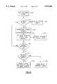
- FIG. 9is a flow diagram for the host system tasks for operating the present product application control system shown in FIG. 8.
- FIG. 10is a flow diagram of a multiple network server start-up for operating the present product application control system shown in FIG. 8.
- FIG. 11is a flow diagram of a single network server for operating the present product application control system shown in FIG. 8.
- FIG. 12is a flow diagram of internal node control for operating the present product application control system shown in FIG. 8.
- FIG. 13is a simplified block diagram of a further embodiment of the invention having an incorporated GIS (geographic information system).
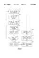
- FIG. 14is a flow diagram similar to FIG. 9 of host system tasks of the embodiment of FIG. 13.
- a currently known product application control system 100includes a host controller 18 located within the cab of a vehicle (not shown), made up of a processor/computer 14 with associated input and output devices including monitor 10 and keyboard 12.
- the host controller 18is responsible for all communication to devices such as actuators 20 including actuator feedback 24 to controller 18 and, for example, a radar device 22 on the chassis of the vehicle.
- actuators 20including actuator feedback 24 to controller 18 and, for example, a radar device 22 on the chassis of the vehicle.
- the addition of loops 26 to the control requirementsadds great complexity to the overall control system 100 wiring.
- FIG. 2a known embodiment 200 for a product application control system similar to that described in the '924 patent to Monson et al. is shown.
- the systemincludes a processor/computer 14 with associated input and output devices including a monitor 10 and a keyboard 12, located within the cab of the vehicle (not shown).
- Computer 14is connected to a single distributed network 210 via a single twisted pair of wires 204 which is run into the cab (not shown). All other system wiring is external to the cab.
- the distributed network control system 200includes multiple nodes 202, theoretically unlimited in number. It can thus be seen that the majority of the wiring displayed in the control system 100 illustrated in FIG. 1 has been moved beyond the cab to the location of the actuators 20 and sensing, feedback 24. It can be seen, therefore, as stated herein before and as specifically described in the '924 patent, that the complex common machine dependent wiring only occurs at the actuators 20 and in a modular fashion.
- node 202 hardwareis generally identical from node 202 to node 202, thereby implying that each machine product application control system 200 is identical, with the only differences being in the number of nodes 202 and the machine (not shown) dependent wiring.
- GUIgraphical user interface
- the system architecturebasically refers to the overall structure and method of accomplishing a task in the environment of the network. That is to say, that once the network is in place, there are many methods and data structures for achieving the same end. If the network use is properly structured, the system design will, to a great extent, become independent of the media and network protocol used.
- EchelonTM network technologyis presently preferred, the same structure as present utilizing EchelonTM network technology would transpose almost directly into similar network environments, e.g., CANs technology. In other words, the present multiple network control system may be used with any existing or contemplated network technology.
- the design of the present inventive multiple network control systemcreates a reliance on processing in the node(s) 202, by virtue of requiring complete PID capabilities and self-diagnostics, and processing capability within the host, to provide commands at predetermined intervals, e.g., one second, to each of the operating loops.
- This clear separation of processingallows the present inventive system to be created with very little reliance on the communication method between the host and particular network nodes.
- Echelon network technologysimplifies this communication, but other network technology, e.g., CANs could also be used.
- FIGS. 3-7are simplified block diagrams showing a host connected to a single network. These figures illustrate some of the alternatives which exist for computing and data storage capabilities of the system. Although a single network is shown the alternatives are equally applicable to a multiple network system.
- FIG. 3illustrates a simplified depiction of the control system 200 in FIG. 2, a known control system used in the agricultural industry for the application of agricultural products, where map 220 and GPS (global positioning system) 230 data structures typically reside in the host 201, and a network 210 carries only setpoint information to the node(s) 202. Each node may be connected to devices such as actuator 20 and feedback 24 as well as to additional nodes.
- control system 200overcomes many of the attendant disadvantages inherent within known closed loop multiple loop control systems such as that illustrated in FIG. 1, it is clearly seen that such a system design continues to place a great burden on the host system.
- one preferred embodiment 400 for the present inventive product application control systemincludes a host 402 with associated input and output devices (e.g., 12, 14 located within the cab of the vehicle).
- Embodiment 400includes a nodal control module 406 located at each node 404. Placing a nodal control module 406 at the location of each actuator device 20 provides for downloading a digital description of a land area 420, for example, thereby making the nodes 404 more independent than nodes 202 utilized in prior known distributed network product application control systems for use in conjunction with self-propelled or towed vehicles.
- location data 430 from a GPS systemis the only information communicated on the network 408 (along with status data). Therefore, this embodiment requires a great deal of memory in the node(s) 404.
- Each node 404has associated with it devices including, for example, an actuator 20 and feedback 24 as described with respect to FIG. 2.
- FIG. 5is yet another preferred embodiment 500 for the present inventive product application control system.
- the systemincludes a host 502 with associated input and output devices, e.g., 12, 14 located within the cab of the vehicle.
- Embodiment 500includes a nodal control module 506 located at each node 504.
- Each nodal control module 506includes data structures at the location of each actuator device 20 which provide for downloading for both the map 520 and location data 530, for example, resulting in the host system 502 acting solely as a supervisor, with the nodes 504 acting in an autonomous fashion.
- GPS data 530can be present on any node 504 within the network 508 with the same result.
- Such an embodiment of the present inventive control systemrequires the greatest processing capabilities for the nodes 504, as well as the greatest memory requirements.
- FIG. 6A further embodiment 600 of the present inventive product application control system is shown in FIG. 6.
- the product application control systemincludes a host 602 with associated input and output devices, e.g., 12, 14 located within the cab of the vehicle.
- Embodiment 600includes a nodal control module 606 located at each node 604.
- Each nodal control module 606includes data storage transfer structures at the location of each actuator device 20 which provide for downloading network based GPS signals 630, for example, in order to simplify the main host 602 design.
- Map data 620is stored in the host. Typically, an extra serial port is required for such a GPS input for the control module 606.
- This embodiment 600is preferred for any network capable system which does not increase processing power within the nodes 604.
- this embodimentwould not increase the processing power for any particular node 604, it would require the node 604 to transmit its location to the host 602 before receiving a command setpoint. Thus, this embodiment 600 could be somewhat slower, and would increase the network traffic over that expected with other embodiments of the present inventive system described above.
- FIG. 7shows a preferred embodiment 700 for distribution of data storage and computer capabilities for the present inventive control system.
- Embodiment 700includes a nodal control module 706 located at each node 704.
- Each nodal control module 706includes data storage and transfer structures at the location of each actuator device which provides for downloading network based GPS signals 730 similar to that described with respect to FIG. 6.
- map data storage and transfer structuresreside in both a host 702 as well as within the network nodes 704.
- map data 720could reside to some extent in more than one location.
- one mapmay correspond to the digital description of the field and the other may describe how product application rates are related to the colors on the map.
- Thiscan be a one dimensional map.
- a look up tablecan reside in the node 704 with setpoint data. This results in network traffic being comprised of the host 702 telling the nodes 704 at what array location the machine is presently located.
- Embodiment 700is advantageous in that communication in the network is minimized.
- the control systemincludes two or more independent networks 810 and 910.
- Networks 810 and 910communicate with a processor/computer 14 having associated input and output devices, e.g., monitor 10 and a keyboard 12 (not shown) through a network interface 50.
- Network interface 50communicates with distributed networks 810 and 910 via cables 808 and 908, respectively.
- Cables 808 and 908each include a twisted pair of conductors for carrying network data between network interface 50 and independent distributed networks 810 and 910 but the present invention is not so limited and other communication cables or methods of communication, including wireless, may be used within the scope of the invention.
- Each distributed networkrequires only one cable per network to enter the cab for full operation of each network and all devices. This is a great simplification from the traditional layout where dozens of wires enter the cab. Thus, troubleshooting and maintenance are greatly simplified and the network has provided a method of self-diagnostics by design. Obviously, if feedback is not received at the node, the problem lies between the node and device, rather than somewhere between the controller and the device.
- Expansion of either distributed network 810 or 910is easily accomplished by simply extending the network to a new node and providing the necessary node/device wiring. This allows the design to be completed in a completely modular fashion as each network remains independent of the others.
- Each distributed network 810 and 910includes multiple nodes 802 and 902, respectively.
- Each of the nodeshas associated with it at least one actuator 20 and, preferably, a feedback device 24, although it will be appreciated that feedback is not always necessary.
- Each of the nodes 802 and 902has a node controller which functions in a manner similar to those described in connection with FIGS. 4-7.
- FIGS. 9-12are flow diagrams of a preferred algorithm used to operate the various functional levels of the control system.
- FIG. 9is a flow diagram of the system tasks performed by the host during operation.
- FIG. 10is a flow diagram of the algorithm which operates the multiple network server start-up.
- FIG. 11is a flow diagram of the operation of each network server.
- FIG. 12is a flow diagram of internal node control operations. It will be understood that the control system operates simultaneously at each of these levels in a coordinated manner.
- the host operating systemis booted up at step 920.
- An expert systemis also started at this time.
- the expert systemis the artificial intelligence device which processes all of the complex calculations associated with the control of product application. It is a system defined by the use of one or more relationships between one or more factors that relate to crop production. The relationships may be mathematical, spatial, user defined or others; examples include recommendation equations for a given nutrient and crop as published by most state universities. Similar expert systems have been described in the '876 and '924 patents to Monson et al. The expert system of the present invention performs similar functions. It will be appreciated, however, that in the present multiple network system much of the responsibility for data storage and performance of calculations has been shifted downward to the node level. Therefore, the expert system as contemplated herein may include components within the host as well as the node controllers.
- step 921an examination of network server applications is made. A determination is made at decision block 922 whether all servers are accounted for. If not, the algorithm loops back to step 921. When all servers are accounted for an examination of all data returned on the network is made at step 923. This data is then analyzed at step 924 to define inputs available, outputs required, and dependencies. The algorithm then proceeds, at step 925, to define setpoints for outputs required at each node based upon the spatial position of the vehicle. In the algorithm shown in FIG. 9, the calculation of setpoints at step 925 assumes that the map resides in the host. As previously discussed with respect to FIGS. 4-7 it is possible to download map information to the nodes or to include map information at both the host and node level. Therefore, depending upon the location of the map data the setpoint calculation may be performed in the host, at the node controller level or some combination thereof.
- independent feedback inputsmay consist of the input from one or more sensors which sense data related to plant development. Such sensors may be used to calculate from soil samples taken periodically during the procedure certain characteristics such as nitrogen level, potassium level, phosphorous level, soil type, pH level, soil temperature, and herbicide, pesticide or fungicide levels, for example. These sensors may operate on a continual or intermittent basis to provide data on a real time basis which is used by the control system for updating the data used in product application control. This data may originally be comprised of pre-loaded maps which may then be updated in real time by the sensor data as the product application process proceeds.
- the information obtained from the sensorsis analyzed for validity and, if valid, is utilized to update the existing data to provide the highest degree of accuracy at the present time. If the sensed data is invalid or inconclusive it is not used. In that case the system would utilize existing data. Therefore, even in the case of a sensor failure where no data is forthcoming the system would continue to be as accurate as the existing map data, which means, even in a worst case scenario, that the system is as accurate as those in use today.
- step 926If feedback is determined to exist at decision block 926 it is analyzed at step 929 to determine its impact and is communicated to the expert system. If no independent feedback inputs exist or if the feedback information has been analyzed and communicated to the expert system then an examination of network status is made at step 929. The status of the networks is communicated to the expert system at step 928 which then loops back to step 922 to start the process over again.
- FIG. 10is a flow diagram of the algorithm used for the multiple network server start-up.
- the operating systemis booted up.
- a determinationis made of the presence of the network. If the network is not sensed a display of system status is made at step 932. If the network is sensed network feedback is interrogated at step 933. A determination of network status from the feedback is made at step 934 and is displayed at step 935.
- decision block 936a determination is made whether all feedback is accounted for. If not, the algorithm loops back to decision block 931 to repeat the process until all feedback has been accounted for.
- decision block 937When all feedback is accounted for a determination is made at decision block 937 of the existence of multiple networks. If multiple networks are not sensed a single network server is begun at step 939. If multiple networks are sensed multiple independent single network servers are begun at step 938, one for each network on the system.
- FIG. 11is a flow diagram of the algorithm used for the single network server.
- Preliminary node configuration datais entered at step 940.
- the configuration datamay be comprised of a short piece of code that is sent via the network to each specific node to configure node firmware for operation.
- the datadefines pin assignments, constants, control technique, system variables and reporting requirements, among others. All executable software on the node is transmitted to the node by the host. The process effectively starts the node control software into operation.
- step 941the status of the node(s) is examined.
- the nodesare initialized at step 942 according to the node configuration data received from the host.
- decision block 943a determination is made whether all nodes have been initialized. If not, the algorithm loops back to step 941 for the process to continue until the initialization of all nodes has been completed.
- the host system requirementsare examined at step 944. It is at this step that the setpoints which were calculated at step 925 of the host system tasks algorithm (FIG. 9) are communicated to the network server. The calculated setpoints for the required outputs are utilized to define the node requirements at step 945. The setpoints for the required outputs are communicated to the nodes at step 946.
- FIG. 12is a flow diagram of the algorithm used for internal node control.
- Setpoint datais received from the host at step 949. This is the data that is communicated by the network server at step 946 of FIG. 11.
- the setpoint datais used to calculate new setpoint PID variables at step 950.
- the PID logicis programmed into the node firmware (software resident in the node non-volatile memory). This allows better control than centralized traditional control. Since the processor is located at the site of the control it is required only to maintain the particular node setpoint to which it has been assigned.
- step 951the actuator is activated in response to host system setpoints.
- Loop feedbackis interrogated at step 952 and the status of the node is determined from the feedback at step 953.
- decision block 954a determination is made whether actuator status has changed. If the status has not changed the algorithm loops back to step 949 to receive additional setpoint data from the host. If the actuator status has changed, for example, as the result of a watch dog alarm known to those of skill in the art, the actuator status change is displayed at step 955.
- New actuator status configuration datais entered at step 956.
- step 957new actuator status with new loop configuration data is entered and the new configuration data is communicated to the host at step 958. The algorithm then loops back to step 949 to receive new setpoint data from the host.
- the multiple-network control system described abovemay be used to accurately control product application in an accurate and dependable manner. Since one embodiment of the control system is reactive to a land area map, there are, however, certain system constraints for that embodiment which may make the system difficult to use for some applications. For example, a land area map which is adequate for dry spreaders without nozzle control may have a pixel size of ten feet on a side. However, in order to control application of liquid fertilizer which requires independent control for each liquid nozzle a pixel size of approximately 1 foot per side is needed. This means that the data size for the land area map grows by a factor of 100. Such a map may be too large to be provided on a single disk, depending upon field size, and would take a great deal of time to load.
- this problemis solved by eliminating the need to utilize a land area map to calculate a spread value of the product. Rather, the spread value in this embodiment is calculated based solely upon the identical raw data that is provided in the map creation process.
- Discussion of the creation of land area mapsis contained in the '876 and '924 patents to Monson et al. and '773 patent to Ortlip, each of which has been incorporated herein by reference in their entirety.
- maps useful for use in the product application vehicles described hereinare disclosed in U.S. patent application Ser. No. 08/452,894 entitled "System and Method for Creating Agricultural Decision and Application Maps for Automated Agricultural Machines", filed on May 30, 1995 and incorporated herein by reference in its entirety.
- This applicationdescribes a system and method for creating agricultural decision and application maps in real time using information obtained from various sources.
- the system disclosedis an improvement over known geographical information systems (GIS) which convert agronomic data to geo-referenced map information.
- GISgeographical information systems
- the control system of this embodiment of the present inventionis based upon the premise that only a very small portion of the information contained on a map is needed at any particular time. Thus, if sufficient processing power is available in the control system, the system can calculate the values which are ordinarily obtained from the land area map on a per position basis, thereby eliminating the need for the direct input of a spatially related digital map.
- the mapmay or may not be created prior to the product application in order to create an estimated plan for the filling and tendering of the vehicle. This map, however, need not be incorporated into the product application control system of this embodiment since control setpoints are calculated directly from the raw geographic information data which is used to create the digital map.
- Raw geographic information dataincludes anything related to plant development characteristics. This raw data may be input into the system using various methods such as by keyboard entry, disk drive, optical system, CD ROM and radio communication to name a few.
- the resolution of the set point datacan be selected by the operator based on the operator's perception of the need for accuracy required for the present job and is not limited by the accuracy of any of the system inputs since all resolution dependent calculations are made in the field.
- the applicator of a liquid fertilizercould apply one a one (1) foot resolution basis while the applicator of a dry fertilizer could apply on a ten (10) foot resolution basis in a manner which is consistent and seamless to the operator.
- the control systemwould preferably include the improved GIS system disclosed in the above-identified patent application.
- the systemhas the ability to incorporate additional and differing sensors such as the sensors which sense characteristics relating to plant development discussed above and to utilize the data provided by those sensors to calculate on a real time basis setpoint values needed for each node.
- Additional sensorsmight include organic matter sensors, real time soil analysis sensors, soil texture sensors or soil terrain sensors.
- Each of these inputswhen combined with data from the GIS system, provide the needed variables to calculate on a real time basis application values based upon present in-field conditions.
- attribute datamay be loaded into the system and used to calculate the control setpoints.
- Attribute dataincludes data that is not specifically tied to a geocoordinate and may include input costs, dealer and farmer information, such as name, address, account identification, etc. This allows very accurate high resolution calculations to be made without resort to a high resolution map which may be too large for the system and/or difficult and time consuming to load.
- FIG. 13is a block diagram of a control system with an incorporated GIS system in accordance with this embodiment of the invention.
- the control systemincludes at least one distributed network 875.
- Network 875communicates with a network sever 852 via cable 854.
- Network server 852provides the interface for communicating data between the network and a host central processing unit such as computer 850. Additional networks may be connected to network server 852 such as by cable 856. Communication between the networks and network server 852 may, alternatively, be implemented in other ways known to those of skill in the art including the use of wireless communication.
- Distributed network 875includes an intelligent control module 858.
- Control module 858further includes a geographic information raw data processor 862 and a controller 868.
- Intelligent control module 858has computing, memory storage and control capabilities which are sufficient to enable it to effectively operate as a standalone autonomous controller.
- Geographic information raw data processor 862is a general purpose computer which has been configured for the specialized purpose of processing raw geographic information data, attribute data and other sensed data as described above and for determining a target rate of application for the product(s) being applied based upon relationships provided by the expert system.
- Each intelligent control modulehas associated with it at least one actuator 20 and preferably a feedback device 24.
- the geographic information raw data processor 862may reside within computer 850. Obviously, this requires less computing and data storage capability at the level of the intelligent control module and places a greater burden on the host computer 850. Additionally, the level of communication between the host computer and the distributed network 875 increases accordingly.
- the geographic information raw data processor 862may be located such that a first portion is contained within intelligent control module 858 and a second portion is contained within computer 850. This illustrates the flexibility of system design which allows the system to be configured according to the particular requirements of the product application system being controlled.
- FIG. 14is a flow diagram of the host system tasks. This diagram is similar to the diagram of FIG. 9, the difference being the inclusion of the GIS system within the control system. It will be understood that the remainder of the system is similar to that discussed with respect to FIGS. 10-12 and includes multiple network server start-up, single network server and internal node control functions.
- the systemis booted up at step 959.
- Network server applicationsare examined at step 960.
- decision block 961a determination is made if all servers are accounted for. If they aren't the algorithm loops back to step 960. If all servers are accounted for all data returned on the network is examined at step 962.
- inputs available, outputs required and dependenciesare defined.
- the defined datais transmitted to step 971 of the GIS system application as will be discussed later and to step 964 for calculation of setpoints based on the spatial position on the vehicle. These setpoints are dependent, in part, upon data provided by the GIS system at step 973.
- the GIS systemis started at step 969.
- data from various input sensorsis examined. This data may be from any desired real time sensors, some of which are identified above. Output requirements based on spatial location are defined at step 971.
- decision block 972a determination is made whether all independent processes are complete. These independent processes may include a multi-layer data analysis of information from various sources. If the independent processes are not complete the algorithm loops back to step 971. If the processes are complete, data sources are coordinated at step 973 and the data is provided for setpoint definition at step 964.
- the inventionis also applicable to areas of the agronomic industry in addition to application of products. For example, it is known to be desirable to adjust the depth of tillage equipment in dependence on soil moisture. However, no presently used equipment is able to control tillage depth on a real time basis. By utilizing the control system of the present invention it is possible to use real time data collected by a soil moisture sensor to adjust tillage depth by controlling an actuator(s) which is responsible for depth control. Thus, the present invention is applicable to any situation where it is desirable to control an agronomic input (e.g., product application, tillage depth, etc.) based upon the real time measurement of data related to crop development.
- an agronomic inpute.g., product application, tillage depth, etc.
Landscapes
- Life Sciences & Earth Sciences (AREA)
- Soil Sciences (AREA)
- Environmental Sciences (AREA)
- Engineering & Computer Science (AREA)
- Mechanical Engineering (AREA)
- Control By Computers (AREA)
Abstract
Description
Claims (29)
Priority Applications (1)
| Application Number | Priority Date | Filing Date | Title |
|---|---|---|---|
| US08/915,847US5870686A (en) | 1995-12-13 | 1997-08-21 | Intelligent Mobile product application control system |
Applications Claiming Priority (2)
| Application Number | Priority Date | Filing Date | Title |
|---|---|---|---|
| US57146795A | 1995-12-13 | 1995-12-13 | |
| US08/915,847US5870686A (en) | 1995-12-13 | 1997-08-21 | Intelligent Mobile product application control system |
Related Parent Applications (1)
| Application Number | Title | Priority Date | Filing Date |
|---|---|---|---|
| US57146795AContinuation | 1995-12-13 | 1995-12-13 |
Publications (1)
| Publication Number | Publication Date |
|---|---|
| US5870686Atrue US5870686A (en) | 1999-02-09 |
Family
ID=24283833
Family Applications (1)
| Application Number | Title | Priority Date | Filing Date |
|---|---|---|---|
| US08/915,847Expired - LifetimeUS5870686A (en) | 1995-12-13 | 1997-08-21 | Intelligent Mobile product application control system |
Country Status (1)
| Country | Link |
|---|---|
| US (1) | US5870686A (en) |
Cited By (85)
| Publication number | Priority date | Publication date | Assignee | Title |
|---|---|---|---|---|
| US5959257A (en)* | 1998-04-15 | 1999-09-28 | Harvestmaster, Inc. | System for weighing material on a conveyor |
| US5961040A (en)* | 1998-03-13 | 1999-10-05 | Dickey-John Corporation | Material application system with programming security |
| US5995894A (en)* | 1997-05-27 | 1999-11-30 | Case Corporation | System for analyzing spatially-variable harvest data by pass |
| US6027053A (en)* | 1998-04-16 | 2000-02-22 | Ag-Chem Equipment | Automatic funnel positioning system for spinner spreader machine |
| US6085135A (en)* | 1997-02-20 | 2000-07-04 | Claas Kgaa | Method for agricultural map image display |
| US6095439A (en)* | 1998-12-02 | 2000-08-01 | Valmont Industries, Inc. | Corner irrigation system including a GPS guidance system |
| US6122520A (en)* | 1998-02-13 | 2000-09-19 | Xerox Corporation | System and method for obtaining and using location specific information |
| US6144338A (en)* | 1998-03-17 | 2000-11-07 | Prc Public Sector. Inc. | Predictive drop and load algorithm for an object-based geographical information system |
| US6150617A (en)* | 1995-09-09 | 2000-11-21 | Agco Limited | Vehicle with weight sensing |
| US6198986B1 (en) | 1999-04-30 | 2001-03-06 | Ag-Chem Equipment Co., Inc. | Pre-charged multi-variable rate crop input applicator machine |
| US6230091B1 (en) | 1997-09-30 | 2001-05-08 | Ag-Chem Equipment Co., Inc. | Variable flow spray nozzle system |
| US6247019B1 (en)* | 1998-03-17 | 2001-06-12 | Prc Public Sector, Inc. | Object-based geographic information system (GIS) |
| US6254018B1 (en) | 1999-12-16 | 2001-07-03 | Valmont Industries, Inc. | Alignment control for long center pivot irrigation systems |
| US6253691B1 (en) | 1999-04-30 | 2001-07-03 | Ag-Chem Equipment Co., Inc. | All wheel steer variable load carrying tractor vehicle |
| US6262741B1 (en) | 1998-03-17 | 2001-07-17 | Prc Public Sector, Inc. | Tiling of object-based geographic information system (GIS) |
| US6313414B1 (en) | 2000-01-31 | 2001-11-06 | Harvestmaster, Inc. | Slope and motion compensator for weighing on a dynamic platform |
| US6356830B1 (en)* | 1998-08-11 | 2002-03-12 | Purdue Research Foundation | System and method for automated measurement of soil pH |
| US20020035431A1 (en)* | 2000-06-05 | 2002-03-21 | Todd Ell | System and method for creating application maps for site-specific farming |
| US20020040300A1 (en)* | 2000-06-05 | 2002-04-04 | Agco | System and method for creating controller application maps for site-specific farming |
| US6525276B1 (en)* | 1998-08-07 | 2003-02-25 | The University Of Georgia Research Foundation, Inc. | Crop yield monitoring system |
| US6570999B1 (en) | 1998-08-17 | 2003-05-27 | Ag-Chem Equipment Co., Inc. | Soil particle and soil analysis system |
| US20030208319A1 (en)* | 2000-06-05 | 2003-11-06 | Agco | System and method for creating demo application maps for site-specific farming |
| US6669105B2 (en) | 2000-09-13 | 2003-12-30 | Adapco, Inc. | Closed-loop mosquito insecticide delivery system and method |
| US6708631B1 (en) | 1999-04-30 | 2004-03-23 | Agco Corporation | Variable payload tractor vehicle with coordinated crop input management system |
| US20050062662A1 (en)* | 2003-09-18 | 2005-03-24 | Mitsumi Electric Co. Ltd | Antenna unit having a wide band |
| US20050201397A1 (en)* | 1998-06-22 | 2005-09-15 | Statsignal Ipc, Llc | Systems and methods for monitoring conditions |
| US20060022048A1 (en)* | 2000-06-07 | 2006-02-02 | Johnson William J | System and method for anonymous location based services |
| US20060098576A1 (en)* | 1996-12-06 | 2006-05-11 | Brownrigg Edwin B | Wireless network system and method for providing same |
| US20070005188A1 (en)* | 2000-06-07 | 2007-01-04 | Johnson William J | System and method for proactive content delivery by situational location |
| US20070034721A1 (en)* | 2005-07-21 | 2007-02-15 | Steve Owenby | Plural bin metering system |
| US20070042803A1 (en)* | 2005-08-16 | 2007-02-22 | Deere & Company, A Delaware Corporation | Mobile station for an unmanned vehicle |
| US20070267524A1 (en)* | 2006-05-18 | 2007-11-22 | David Mack | Gps control system and method for irrigation systems |
| US20080004993A1 (en)* | 2006-05-08 | 2008-01-03 | Horspool Jason A | System and method for managing physical and logical assets |
| US20080167083A1 (en)* | 2007-01-07 | 2008-07-10 | Wyld Jeremy A | Method, Device, and Graphical User Interface for Location-Based Dialing |
| US20080186898A1 (en)* | 2005-01-25 | 2008-08-07 | Sipco, Llc | Wireless Network Protocol System And Methods |
| US20080191054A1 (en)* | 2007-02-09 | 2008-08-14 | Tsd Integrated Controls, Llc | Method and system for applying materials to crops |
| US20090005082A1 (en)* | 2007-06-28 | 2009-01-01 | Apple Inc. | Disfavored route progressions or locations |
| US20090005005A1 (en)* | 2007-06-28 | 2009-01-01 | Apple Inc. | Mobile Device Base Station |
| US20090005077A1 (en)* | 2007-06-28 | 2009-01-01 | Apple Inc. | Location-Based Services |
| US20090005965A1 (en)* | 2007-06-28 | 2009-01-01 | Apple Inc. | Adaptive Route Guidance Based on Preferences |
| US20090005080A1 (en)* | 2007-06-28 | 2009-01-01 | Apple Inc. | Location-Aware Mobile Device |
| US20090005978A1 (en)* | 2007-06-28 | 2009-01-01 | Apple Inc. | Route Reference |
| US20090005072A1 (en)* | 2007-06-28 | 2009-01-01 | Apple Inc. | Integration of User Applications in a Mobile Device |
| US20090005070A1 (en)* | 2007-06-28 | 2009-01-01 | Apple Inc. | Synchronizing mobile and vehicle devices |
| US20090005018A1 (en)* | 2007-06-28 | 2009-01-01 | Apple Inc. | Route Sharing and Location |
| US20090005975A1 (en)* | 2007-06-28 | 2009-01-01 | Apple Inc. | Adaptive Mobile Device Navigation |
| US20090003659A1 (en)* | 2007-06-28 | 2009-01-01 | Apple Inc. | Location based tracking |
| US20090005076A1 (en)* | 2007-06-28 | 2009-01-01 | Scott Forstall | Location-Based Information Services |
| US20090005981A1 (en)* | 2007-06-28 | 2009-01-01 | Apple Inc. | Integration of Map Services and User Applications in a Mobile Device |
| US20090005068A1 (en)* | 2007-06-28 | 2009-01-01 | Apple Inc. | Location-Based Emergency Information |
| US20090089706A1 (en)* | 2007-10-01 | 2009-04-02 | Apple Inc. | Varying User Interface Element Based on Movement |
| US20090098857A1 (en)* | 2007-10-10 | 2009-04-16 | Dallas De Atley | Securely Locating a Device |
| US20090177385A1 (en)* | 2008-01-06 | 2009-07-09 | Apple Inc. | Graphical user interface for presenting location information |
| US20090182492A1 (en)* | 2008-01-10 | 2009-07-16 | Apple Inc. | Adaptive Navigation System for Estimating Travel Times |
| US20090281724A1 (en)* | 2008-05-12 | 2009-11-12 | Apple Inc. | Map service with network-based query for search |
| US20090286549A1 (en)* | 2008-05-16 | 2009-11-19 | Apple Inc. | Location Determination |
| US20090326815A1 (en)* | 2008-05-02 | 2009-12-31 | Apple Inc. | Position Fix Indicator |
| US20090325603A1 (en)* | 2008-06-30 | 2009-12-31 | Apple Inc. | Location sharing |
| US20100039984A1 (en)* | 1996-12-06 | 2010-02-18 | Brownrigg Edwin B | Systems and methods for facilitating wireless network communication, satellite-based wireless network systems, and aircraft-based wireless network systems, and related methods |
| US20100070758A1 (en)* | 2008-09-18 | 2010-03-18 | Apple Inc. | Group Formation Using Anonymous Broadcast Information |
| US20100250054A1 (en)* | 2001-10-30 | 2010-09-30 | Sipco, Llc | System And Method For Transmitting Pollution Information Over An Integrated Wireless Network |
| US20100279652A1 (en)* | 2009-05-01 | 2010-11-04 | Apple Inc. | Remotely Locating and Commanding a Mobile Device |
| US20100279673A1 (en)* | 2009-05-01 | 2010-11-04 | Apple Inc. | Remotely Locating and Commanding a Mobile Device |
| US20100279675A1 (en)* | 2009-05-01 | 2010-11-04 | Apple Inc. | Remotely Locating and Commanding a Mobile Device |
| US20110015832A1 (en)* | 2007-10-04 | 2011-01-20 | David Stanley Hoyle | Spreader with gps guided spread pattern |
| WO2011069563A1 (en)* | 2009-12-10 | 2011-06-16 | Unity Ag | Method and system for monitoring and controlled distribution of fertilizers |
| US20110208857A1 (en)* | 2010-02-03 | 2011-08-25 | Odyssey Software, Inc. | Method, system, and computer readable medium for gathering usage statistics |
| US8013732B2 (en) | 1998-06-22 | 2011-09-06 | Sipco, Llc | Systems and methods for monitoring and controlling remote devices |
| US8031650B2 (en) | 2004-03-03 | 2011-10-04 | Sipco, Llc | System and method for monitoring remote devices with a dual-mode wireless communication protocol |
| US8073565B2 (en) | 2000-06-07 | 2011-12-06 | Apple Inc. | System and method for alerting a first mobile data processing system nearby a second mobile data processing system |
| US8311526B2 (en) | 2007-06-28 | 2012-11-13 | Apple Inc. | Location-based categorical information services |
| US8332402B2 (en) | 2007-06-28 | 2012-12-11 | Apple Inc. | Location based media items |
| US8385964B2 (en) | 2005-04-04 | 2013-02-26 | Xone, Inc. | Methods and apparatuses for geospatial-based sharing of information by multiple devices |
| US8410931B2 (en) | 1998-06-22 | 2013-04-02 | Sipco, Llc | Mobile inventory unit monitoring systems and methods |
| US8446884B2 (en) | 2004-03-03 | 2013-05-21 | Sipco, Llc | Dual-mode communication devices, methods and systems |
| US8489063B2 (en) | 2001-10-24 | 2013-07-16 | Sipco, Llc | Systems and methods for providing emergency messages to a mobile device |
| US8666357B2 (en) | 2001-10-24 | 2014-03-04 | Sipco, Llc | System and method for transmitting an emergency message over an integrated wireless network |
| US8924588B2 (en) | 1999-03-18 | 2014-12-30 | Sipco, Llc | Systems and methods for controlling communication between a host computer and communication devices |
| US8964708B2 (en) | 1998-06-22 | 2015-02-24 | Sipco Llc | Systems and methods for monitoring and controlling remote devices |
| US9342381B2 (en) | 2011-02-03 | 2016-05-17 | Symantec Corporation | Method and system for establishing a DLP-compliant environment |
| WO2018006366A1 (en)* | 2016-07-07 | 2018-01-11 | 深圳狗尾草智能科技有限公司 | Interactive information-based scoring method and system |
| US9907224B2 (en) | 2013-05-13 | 2018-03-06 | Clean Seed Agricultural Technologies Inc. | System for variable-ratio blending of multiple agricultural products for delivery via a ported opener |
| WO2019084643A1 (en)* | 2017-10-30 | 2019-05-09 | Stara S/a. Industria De Implementos Agrícolas | Methodology principally for planting |
| WO2019084644A1 (en)* | 2017-10-30 | 2019-05-09 | Stara S/a. Industria De Implementos Agrícolas | Automatic system for implementing a methodology principally for planting |
| US11895941B2 (en) | 2019-09-23 | 2024-02-13 | Cnh Industrial America Llc | Tillage system with variable fertilizer application |
Citations (8)
| Publication number | Priority date | Publication date | Assignee | Title |
|---|---|---|---|---|
| US3648930A (en)* | 1970-10-08 | 1972-03-14 | Irrigation Power Equip Inc | Chemical solution spray system for self-propelled sprinkling apparatus |
| US3871587A (en)* | 1972-05-31 | 1975-03-18 | Josef Gail | Method of and apparatus for spreading fertilizer |
| US4630773A (en)* | 1984-11-06 | 1986-12-23 | Soil Teq., Inc. | Method and apparatus for spreading fertilizer |
| US5052627A (en)* | 1990-05-23 | 1991-10-01 | Charles Balmer | Spreading of particulate material |
| US5220876A (en)* | 1992-06-22 | 1993-06-22 | Ag-Chem Equipment Co., Inc. | Variable rate application system |
| US5242120A (en)* | 1991-12-06 | 1993-09-07 | Larry Barber | Multi component fertilizer supply system for a mobile spreader |
| US5442349A (en)* | 1992-10-12 | 1995-08-15 | Masprodenkoh Kabushikikaisha | Navigation system with route determination process capable of determining a desired route readily and quickly |
| US5532690A (en)* | 1995-04-04 | 1996-07-02 | Itt Corporation | Apparatus and method for monitoring and bounding the path of a ground vehicle |
- 1997
- 1997-08-21USUS08/915,847patent/US5870686A/ennot_activeExpired - Lifetime
Patent Citations (8)
| Publication number | Priority date | Publication date | Assignee | Title |
|---|---|---|---|---|
| US3648930A (en)* | 1970-10-08 | 1972-03-14 | Irrigation Power Equip Inc | Chemical solution spray system for self-propelled sprinkling apparatus |
| US3871587A (en)* | 1972-05-31 | 1975-03-18 | Josef Gail | Method of and apparatus for spreading fertilizer |
| US4630773A (en)* | 1984-11-06 | 1986-12-23 | Soil Teq., Inc. | Method and apparatus for spreading fertilizer |
| US5052627A (en)* | 1990-05-23 | 1991-10-01 | Charles Balmer | Spreading of particulate material |
| US5242120A (en)* | 1991-12-06 | 1993-09-07 | Larry Barber | Multi component fertilizer supply system for a mobile spreader |
| US5220876A (en)* | 1992-06-22 | 1993-06-22 | Ag-Chem Equipment Co., Inc. | Variable rate application system |
| US5442349A (en)* | 1992-10-12 | 1995-08-15 | Masprodenkoh Kabushikikaisha | Navigation system with route determination process capable of determining a desired route readily and quickly |
| US5532690A (en)* | 1995-04-04 | 1996-07-02 | Itt Corporation | Apparatus and method for monitoring and bounding the path of a ground vehicle |
Cited By (234)
| Publication number | Priority date | Publication date | Assignee | Title |
|---|---|---|---|---|
| US6150617A (en)* | 1995-09-09 | 2000-11-21 | Agco Limited | Vehicle with weight sensing |
| US20100039984A1 (en)* | 1996-12-06 | 2010-02-18 | Brownrigg Edwin B | Systems and methods for facilitating wireless network communication, satellite-based wireless network systems, and aircraft-based wireless network systems, and related methods |
| US8625496B2 (en) | 1996-12-06 | 2014-01-07 | Ipco, Llc | Wireless network system and method for providing same |
| US20100017465A1 (en)* | 1996-12-06 | 2010-01-21 | Brownrigg Edwin B | Wireless network system and method for providing same |
| US8982856B2 (en) | 1996-12-06 | 2015-03-17 | Ipco, Llc | Systems and methods for facilitating wireless network communication, satellite-based wireless network systems, and aircraft-based wireless network systems, and related methods |
| US20060098576A1 (en)* | 1996-12-06 | 2006-05-11 | Brownrigg Edwin B | Wireless network system and method for providing same |
| US8233471B2 (en) | 1996-12-06 | 2012-07-31 | Ipco, Llc | Wireless network system and method for providing same |
| US8000314B2 (en) | 1996-12-06 | 2011-08-16 | Ipco, Llc | Wireless network system and method for providing same |
| US6085135A (en)* | 1997-02-20 | 2000-07-04 | Claas Kgaa | Method for agricultural map image display |
| US5995894A (en)* | 1997-05-27 | 1999-11-30 | Case Corporation | System for analyzing spatially-variable harvest data by pass |
| US6230091B1 (en) | 1997-09-30 | 2001-05-08 | Ag-Chem Equipment Co., Inc. | Variable flow spray nozzle system |
| US6122520A (en)* | 1998-02-13 | 2000-09-19 | Xerox Corporation | System and method for obtaining and using location specific information |
| USRE42927E1 (en) | 1998-02-13 | 2011-11-15 | Apple Inc. | System and method for obtaining and using location specific information |
| US5961040A (en)* | 1998-03-13 | 1999-10-05 | Dickey-John Corporation | Material application system with programming security |
| US6262741B1 (en) | 1998-03-17 | 2001-07-17 | Prc Public Sector, Inc. | Tiling of object-based geographic information system (GIS) |
| US6247019B1 (en)* | 1998-03-17 | 2001-06-12 | Prc Public Sector, Inc. | Object-based geographic information system (GIS) |
| US6144338A (en)* | 1998-03-17 | 2000-11-07 | Prc Public Sector. Inc. | Predictive drop and load algorithm for an object-based geographical information system |
| US5959257A (en)* | 1998-04-15 | 1999-09-28 | Harvestmaster, Inc. | System for weighing material on a conveyor |
| US6066809A (en)* | 1998-04-15 | 2000-05-23 | Harvestmaster, Inc. | Weighing material on a conveyor |
| US6027053A (en)* | 1998-04-16 | 2000-02-22 | Ag-Chem Equipment | Automatic funnel positioning system for spinner spreader machine |
| US8410931B2 (en) | 1998-06-22 | 2013-04-02 | Sipco, Llc | Mobile inventory unit monitoring systems and methods |
| US9571582B2 (en) | 1998-06-22 | 2017-02-14 | Sipco, Llc | Systems and methods for monitoring and controlling remote devices |
| US8223010B2 (en) | 1998-06-22 | 2012-07-17 | Sipco Llc | Systems and methods for monitoring vehicle parking |
| US8212667B2 (en) | 1998-06-22 | 2012-07-03 | Sipco, Llc | Automotive diagnostic data monitoring systems and methods |
| US8964708B2 (en) | 1998-06-22 | 2015-02-24 | Sipco Llc | Systems and methods for monitoring and controlling remote devices |
| US8013732B2 (en) | 1998-06-22 | 2011-09-06 | Sipco, Llc | Systems and methods for monitoring and controlling remote devices |
| US9430936B2 (en) | 1998-06-22 | 2016-08-30 | Sipco Llc | Systems and methods for monitoring and controlling remote devices |
| US9129497B2 (en) | 1998-06-22 | 2015-09-08 | Statsignal Systems, Inc. | Systems and methods for monitoring conditions |
| US8064412B2 (en) | 1998-06-22 | 2011-11-22 | Sipco, Llc | Systems and methods for monitoring conditions |
| US9691263B2 (en) | 1998-06-22 | 2017-06-27 | Sipco, Llc | Systems and methods for monitoring conditions |
| US20050201397A1 (en)* | 1998-06-22 | 2005-09-15 | Statsignal Ipc, Llc | Systems and methods for monitoring conditions |
| US6525276B1 (en)* | 1998-08-07 | 2003-02-25 | The University Of Georgia Research Foundation, Inc. | Crop yield monitoring system |
| US6356830B1 (en)* | 1998-08-11 | 2002-03-12 | Purdue Research Foundation | System and method for automated measurement of soil pH |
| US6570999B1 (en) | 1998-08-17 | 2003-05-27 | Ag-Chem Equipment Co., Inc. | Soil particle and soil analysis system |
| US6095439A (en)* | 1998-12-02 | 2000-08-01 | Valmont Industries, Inc. | Corner irrigation system including a GPS guidance system |
| US8924588B2 (en) | 1999-03-18 | 2014-12-30 | Sipco, Llc | Systems and methods for controlling communication between a host computer and communication devices |
| US8924587B2 (en) | 1999-03-18 | 2014-12-30 | Sipco, Llc | Systems and methods for controlling communication between a host computer and communication devices |
| US8930571B2 (en) | 1999-03-18 | 2015-01-06 | Sipco, LLP | Systems and methods for controlling communication between a host computer and communication devices |
| US6253691B1 (en) | 1999-04-30 | 2001-07-03 | Ag-Chem Equipment Co., Inc. | All wheel steer variable load carrying tractor vehicle |
| US6394011B2 (en) | 1999-04-30 | 2002-05-28 | Ag-Chem Equipment Company, Inc. | All wheel steer variable load carrying tractor vehicle |
| US6198986B1 (en) | 1999-04-30 | 2001-03-06 | Ag-Chem Equipment Co., Inc. | Pre-charged multi-variable rate crop input applicator machine |
| US6708631B1 (en) | 1999-04-30 | 2004-03-23 | Agco Corporation | Variable payload tractor vehicle with coordinated crop input management system |
| US6584919B2 (en)* | 1999-04-30 | 2003-07-01 | Agco Corporation | All wheel steer variable load carrying tractor vehicle |
| US6254018B1 (en) | 1999-12-16 | 2001-07-03 | Valmont Industries, Inc. | Alignment control for long center pivot irrigation systems |
| US6313414B1 (en) | 2000-01-31 | 2001-11-06 | Harvestmaster, Inc. | Slope and motion compensator for weighing on a dynamic platform |
| US20020035431A1 (en)* | 2000-06-05 | 2002-03-21 | Todd Ell | System and method for creating application maps for site-specific farming |
| US20020040300A1 (en)* | 2000-06-05 | 2002-04-04 | Agco | System and method for creating controller application maps for site-specific farming |
| US20030208319A1 (en)* | 2000-06-05 | 2003-11-06 | Agco | System and method for creating demo application maps for site-specific farming |
| US20080030308A1 (en)* | 2000-06-07 | 2008-02-07 | Johnson William J | System and method for situational location relevant invocable speed reference |
| US20070005188A1 (en)* | 2000-06-07 | 2007-01-04 | Johnson William J | System and method for proactive content delivery by situational location |
| US9100793B2 (en) | 2000-06-07 | 2015-08-04 | Apple Inc. | System and method for alerting a first mobile data processing system nearby a second mobile data processing system |
| US8984059B2 (en) | 2000-06-07 | 2015-03-17 | Apple Inc. | Mobile data processing system moving interest radius |
| US8031050B2 (en) | 2000-06-07 | 2011-10-04 | Apple Inc. | System and method for situational location relevant invocable speed reference |
| US8963686B2 (en) | 2000-06-07 | 2015-02-24 | Apple Inc. | System and method for situational location relevant invocable speed reference |
| US9317867B2 (en) | 2000-06-07 | 2016-04-19 | Apple Inc. | System and method for situational location relevant invocable speed reference |
| US8060389B2 (en) | 2000-06-07 | 2011-11-15 | Apple Inc. | System and method for anonymous location based services |
| US8930233B2 (en) | 2000-06-07 | 2015-01-06 | Apple Inc. | System and method for anonymous location based services |
| US7710290B2 (en) | 2000-06-07 | 2010-05-04 | Apple Inc. | System and method for situational location relevant invocable speed reference |
| US20070276587A1 (en)* | 2000-06-07 | 2007-11-29 | Johnson William J | System and method for internet connected service providing heterogeneous mobile systems with situational location relevant content |
| US20060022048A1 (en)* | 2000-06-07 | 2006-02-02 | Johnson William J | System and method for anonymous location based services |
| US20070233387A1 (en)* | 2000-06-07 | 2007-10-04 | Johnson William J | System and method for situational location informative shopping cart |
| US8538685B2 (en) | 2000-06-07 | 2013-09-17 | Apple Inc. | System and method for internet connected service providing heterogeneous mobile systems with situational location relevant content |
| US8489669B2 (en) | 2000-06-07 | 2013-07-16 | Apple Inc. | Mobile data processing system moving interest radius |
| US8073565B2 (en) | 2000-06-07 | 2011-12-06 | Apple Inc. | System and method for alerting a first mobile data processing system nearby a second mobile data processing system |
| US6926211B2 (en) | 2000-09-13 | 2005-08-09 | Adapco, Inc. | Closed-loop mosquito insecticide delivery system and method |
| US6669105B2 (en) | 2000-09-13 | 2003-12-30 | Adapco, Inc. | Closed-loop mosquito insecticide delivery system and method |
| US20040217199A1 (en)* | 2000-09-13 | 2004-11-04 | Adapco, Inc. | Spray delivery system |
| US7213772B2 (en) | 2000-09-13 | 2007-05-08 | Adapco, Inc. | Spray delivery system |
| US9615226B2 (en) | 2001-10-24 | 2017-04-04 | Sipco, Llc | System and method for transmitting an emergency message over an integrated wireless network |
| US10149129B2 (en) | 2001-10-24 | 2018-12-04 | Sipco, Llc | Systems and methods for providing emergency messages to a mobile device |
| US10687194B2 (en) | 2001-10-24 | 2020-06-16 | Sipco, Llc | Systems and methods for providing emergency messages to a mobile device |
| US9282029B2 (en) | 2001-10-24 | 2016-03-08 | Sipco, Llc. | System and method for transmitting an emergency message over an integrated wireless network |
| US8489063B2 (en) | 2001-10-24 | 2013-07-16 | Sipco, Llc | Systems and methods for providing emergency messages to a mobile device |
| US8666357B2 (en) | 2001-10-24 | 2014-03-04 | Sipco, Llc | System and method for transmitting an emergency message over an integrated wireless network |
| US9111240B2 (en) | 2001-10-30 | 2015-08-18 | Sipco, Llc. | System and method for transmitting pollution information over an integrated wireless network |
| US20100250054A1 (en)* | 2001-10-30 | 2010-09-30 | Sipco, Llc | System And Method For Transmitting Pollution Information Over An Integrated Wireless Network |
| US8171136B2 (en) | 2001-10-30 | 2012-05-01 | Sipco, Llc | System and method for transmitting pollution information over an integrated wireless network |
| US9515691B2 (en) | 2001-10-30 | 2016-12-06 | Sipco, Llc. | System and method for transmitting pollution information over an integrated wireless network |
| US20050062662A1 (en)* | 2003-09-18 | 2005-03-24 | Mitsumi Electric Co. Ltd | Antenna unit having a wide band |
| US8031650B2 (en) | 2004-03-03 | 2011-10-04 | Sipco, Llc | System and method for monitoring remote devices with a dual-mode wireless communication protocol |
| US8446884B2 (en) | 2004-03-03 | 2013-05-21 | Sipco, Llc | Dual-mode communication devices, methods and systems |
| US8379564B2 (en) | 2004-03-03 | 2013-02-19 | Sipco, Llc | System and method for monitoring remote devices with a dual-mode wireless communication protocol |
| US9439126B2 (en) | 2005-01-25 | 2016-09-06 | Sipco, Llc | Wireless network protocol system and methods |
| US11039371B2 (en) | 2005-01-25 | 2021-06-15 | Sipco, Llc | Wireless network protocol systems and methods |
| US20080186898A1 (en)* | 2005-01-25 | 2008-08-07 | Sipco, Llc | Wireless Network Protocol System And Methods |
| US9860820B2 (en) | 2005-01-25 | 2018-01-02 | Sipco, Llc | Wireless network protocol systems and methods |
| US10356687B2 (en) | 2005-01-25 | 2019-07-16 | Sipco, Llc | Wireless network protocol systems and methods |
| US9854394B1 (en) | 2005-04-04 | 2017-12-26 | X One, Inc. | Ad hoc location sharing group between first and second cellular wireless devices |
| US9253616B1 (en) | 2005-04-04 | 2016-02-02 | X One, Inc. | Apparatus and method for obtaining content on a cellular wireless device based on proximity |
| US10791414B2 (en) | 2005-04-04 | 2020-09-29 | X One, Inc. | Location sharing for commercial and proprietary content applications |
| US8798593B2 (en) | 2005-04-04 | 2014-08-05 | X One, Inc. | Location sharing and tracking using mobile phones or other wireless devices |
| US10750311B2 (en) | 2005-04-04 | 2020-08-18 | X One, Inc. | Application-based tracking and mapping function in connection with vehicle-based services provision |
| US10750309B2 (en) | 2005-04-04 | 2020-08-18 | X One, Inc. | Ad hoc location sharing group establishment for wireless devices with designated meeting point |
| US10750310B2 (en) | 2005-04-04 | 2020-08-18 | X One, Inc. | Temporary location sharing group with event based termination |
| US8798647B1 (en) | 2005-04-04 | 2014-08-05 | X One, Inc. | Tracking proximity of services provider to services consumer |
| US11356799B2 (en) | 2005-04-04 | 2022-06-07 | X One, Inc. | Fleet location sharing application in association with services provision |
| US10341809B2 (en) | 2005-04-04 | 2019-07-02 | X One, Inc. | Location sharing with facilitated meeting point definition |
| US10341808B2 (en) | 2005-04-04 | 2019-07-02 | X One, Inc. | Location sharing for commercial and proprietary content applications |
| US10313826B2 (en) | 2005-04-04 | 2019-06-04 | X One, Inc. | Location sharing and map support in connection with services request |
| US8385964B2 (en) | 2005-04-04 | 2013-02-26 | Xone, Inc. | Methods and apparatuses for geospatial-based sharing of information by multiple devices |
| US10200811B1 (en) | 2005-04-04 | 2019-02-05 | X One, Inc. | Map presentation on cellular device showing positions of multiple other wireless device users |
| US10165059B2 (en) | 2005-04-04 | 2018-12-25 | X One, Inc. | Methods, systems and apparatuses for the formation and tracking of location sharing groups |
| US8831635B2 (en) | 2005-04-04 | 2014-09-09 | X One, Inc. | Methods and apparatuses for transmission of an alert to multiple devices |
| US8750898B2 (en) | 2005-04-04 | 2014-06-10 | X One, Inc. | Methods and systems for annotating target locations |
| US9031581B1 (en) | 2005-04-04 | 2015-05-12 | X One, Inc. | Apparatus and method for obtaining content on a cellular wireless device based on proximity to other wireless devices |
| US10149092B1 (en) | 2005-04-04 | 2018-12-04 | X One, Inc. | Location sharing service between GPS-enabled wireless devices, with shared target location exchange |
| US9967704B1 (en) | 2005-04-04 | 2018-05-08 | X One, Inc. | Location sharing group map management |
| US9955298B1 (en) | 2005-04-04 | 2018-04-24 | X One, Inc. | Methods, systems and apparatuses for the formation and tracking of location sharing groups |
| US9942705B1 (en) | 2005-04-04 | 2018-04-10 | X One, Inc. | Location sharing group for services provision |
| US9883360B1 (en) | 2005-04-04 | 2018-01-30 | X One, Inc. | Rendez vous management using mobile phones or other mobile devices |
| US11778415B2 (en) | 2005-04-04 | 2023-10-03 | Xone, Inc. | Location sharing application in association with services provision |
| US10856099B2 (en) | 2005-04-04 | 2020-12-01 | X One, Inc. | Application-based two-way tracking and mapping function with selected individuals |
| US8798645B2 (en) | 2005-04-04 | 2014-08-05 | X One, Inc. | Methods and systems for sharing position data and tracing paths between mobile-device users |
| US10299071B2 (en) | 2005-04-04 | 2019-05-21 | X One, Inc. | Server-implemented methods and systems for sharing location amongst web-enabled cell phones |
| US9749790B1 (en) | 2005-04-04 | 2017-08-29 | X One, Inc. | Rendez vous management using mobile phones or other mobile devices |
| US8712441B2 (en) | 2005-04-04 | 2014-04-29 | Xone, Inc. | Methods and systems for temporarily sharing position data between mobile-device users |
| US9167558B2 (en) | 2005-04-04 | 2015-10-20 | X One, Inc. | Methods and systems for sharing position data between subscribers involving multiple wireless providers |
| US9736618B1 (en) | 2005-04-04 | 2017-08-15 | X One, Inc. | Techniques for sharing relative position between mobile devices |
| US9185522B1 (en) | 2005-04-04 | 2015-11-10 | X One, Inc. | Apparatus and method to transmit content to a cellular wireless device based on proximity to other wireless devices |
| US9654921B1 (en) | 2005-04-04 | 2017-05-16 | X One, Inc. | Techniques for sharing position data between first and second devices |
| US9615204B1 (en) | 2005-04-04 | 2017-04-04 | X One, Inc. | Techniques for communication within closed groups of mobile devices |
| US9854402B1 (en) | 2005-04-04 | 2017-12-26 | X One, Inc. | Formation of wireless device location sharing group |
| US8538458B2 (en) | 2005-04-04 | 2013-09-17 | X One, Inc. | Location sharing and tracking using mobile phones or other wireless devices |
| US9584960B1 (en) | 2005-04-04 | 2017-02-28 | X One, Inc. | Rendez vous management using mobile phones or other mobile devices |
| US9467832B2 (en) | 2005-04-04 | 2016-10-11 | X One, Inc. | Methods and systems for temporarily sharing position data between mobile-device users |
| US7380733B2 (en) | 2005-07-21 | 2008-06-03 | Barron & Brothers International | Plural bin metering system |
| US20070034721A1 (en)* | 2005-07-21 | 2007-02-15 | Steve Owenby | Plural bin metering system |
| US8442700B2 (en) | 2005-08-16 | 2013-05-14 | Deere & Company | Mobile station for unmanned vehicle |
| US7957850B2 (en) | 2005-08-16 | 2011-06-07 | Deere & Company | Mobile station for unmanned vehicle |
| US20090298539A1 (en)* | 2005-08-16 | 2009-12-03 | Noel Wayne Anderson | Mobile Station for Unmanned Vehicle |
| US20090299582A1 (en)* | 2005-08-16 | 2009-12-03 | Noel Wayne Anderson | Mobile Station for Unmanned Vehicle |
| US20070042803A1 (en)* | 2005-08-16 | 2007-02-22 | Deere & Company, A Delaware Corporation | Mobile station for an unmanned vehicle |
| US7610122B2 (en) | 2005-08-16 | 2009-10-27 | Deere & Company | Mobile station for an unmanned vehicle |
| US20080004993A1 (en)* | 2006-05-08 | 2008-01-03 | Horspool Jason A | System and method for managing physical and logical assets |
| US20070267524A1 (en)* | 2006-05-18 | 2007-11-22 | David Mack | Gps control system and method for irrigation systems |
| US20080167083A1 (en)* | 2007-01-07 | 2008-07-10 | Wyld Jeremy A | Method, Device, and Graphical User Interface for Location-Based Dialing |
| WO2008097283A1 (en)* | 2007-02-09 | 2008-08-14 | Tsd Integrated Controls, Llc | Method and system for applying materials to crops |
| US20080191054A1 (en)* | 2007-02-09 | 2008-08-14 | Tsd Integrated Controls, Llc | Method and system for applying materials to crops |
| US7848865B2 (en) | 2007-02-09 | 2010-12-07 | Tsd Integrated Controls, Llc | Method and system for applying materials to crops |
| US9891055B2 (en) | 2007-06-28 | 2018-02-13 | Apple Inc. | Location based tracking |
| US20090005005A1 (en)* | 2007-06-28 | 2009-01-01 | Apple Inc. | Mobile Device Base Station |
| US12228411B2 (en) | 2007-06-28 | 2025-02-18 | Apple Inc. | Location based tracking |
| US8774825B2 (en) | 2007-06-28 | 2014-07-08 | Apple Inc. | Integration of map services with user applications in a mobile device |
| US8762056B2 (en) | 2007-06-28 | 2014-06-24 | Apple Inc. | Route reference |
| US20090005076A1 (en)* | 2007-06-28 | 2009-01-01 | Scott Forstall | Location-Based Information Services |
| US20090003659A1 (en)* | 2007-06-28 | 2009-01-01 | Apple Inc. | Location based tracking |
| US12114284B2 (en) | 2007-06-28 | 2024-10-08 | Apple Inc. | Location-aware mobile device |
| US8924144B2 (en) | 2007-06-28 | 2014-12-30 | Apple Inc. | Location based tracking |
| US20090005975A1 (en)* | 2007-06-28 | 2009-01-01 | Apple Inc. | Adaptive Mobile Device Navigation |
| US20090005018A1 (en)* | 2007-06-28 | 2009-01-01 | Apple Inc. | Route Sharing and Location |
| US20090005070A1 (en)* | 2007-06-28 | 2009-01-01 | Apple Inc. | Synchronizing mobile and vehicle devices |
| US20090005072A1 (en)* | 2007-06-28 | 2009-01-01 | Apple Inc. | Integration of User Applications in a Mobile Device |
| US11665665B2 (en) | 2007-06-28 | 2023-05-30 | Apple Inc. | Location-aware mobile device |
| US20090005978A1 (en)* | 2007-06-28 | 2009-01-01 | Apple Inc. | Route Reference |
| US20090005080A1 (en)* | 2007-06-28 | 2009-01-01 | Apple Inc. | Location-Aware Mobile Device |
| US11419092B2 (en) | 2007-06-28 | 2022-08-16 | Apple Inc. | Location-aware mobile device |
| US8738039B2 (en) | 2007-06-28 | 2014-05-27 | Apple Inc. | Location-based categorical information services |
| US9066199B2 (en) | 2007-06-28 | 2015-06-23 | Apple Inc. | Location-aware mobile device |
| US20090005965A1 (en)* | 2007-06-28 | 2009-01-01 | Apple Inc. | Adaptive Route Guidance Based on Preferences |
| US20090005077A1 (en)* | 2007-06-28 | 2009-01-01 | Apple Inc. | Location-Based Services |
| US9109904B2 (en) | 2007-06-28 | 2015-08-18 | Apple Inc. | Integration of map services and user applications in a mobile device |
| US9131342B2 (en) | 2007-06-28 | 2015-09-08 | Apple Inc. | Location-based categorical information services |
| US8385946B2 (en) | 2007-06-28 | 2013-02-26 | Apple Inc. | Disfavored route progressions or locations |
| US8694026B2 (en) | 2007-06-28 | 2014-04-08 | Apple Inc. | Location based services |
| US11221221B2 (en) | 2007-06-28 | 2022-01-11 | Apple Inc. | Location based tracking |
| US10952180B2 (en) | 2007-06-28 | 2021-03-16 | Apple Inc. | Location-aware mobile device |
| US10508921B2 (en) | 2007-06-28 | 2019-12-17 | Apple Inc. | Location based tracking |
| US20090005082A1 (en)* | 2007-06-28 | 2009-01-01 | Apple Inc. | Disfavored route progressions or locations |
| US9310206B2 (en) | 2007-06-28 | 2016-04-12 | Apple Inc. | Location based tracking |
| US20090005981A1 (en)* | 2007-06-28 | 2009-01-01 | Apple Inc. | Integration of Map Services and User Applications in a Mobile Device |
| US10458800B2 (en) | 2007-06-28 | 2019-10-29 | Apple Inc. | Disfavored route progressions or locations |
| US10412703B2 (en) | 2007-06-28 | 2019-09-10 | Apple Inc. | Location-aware mobile device |
| US9414198B2 (en) | 2007-06-28 | 2016-08-09 | Apple Inc. | Location-aware mobile device |
| US8108144B2 (en) | 2007-06-28 | 2012-01-31 | Apple Inc. | Location based tracking |
| US8175802B2 (en) | 2007-06-28 | 2012-05-08 | Apple Inc. | Adaptive route guidance based on preferences |
| US8180379B2 (en) | 2007-06-28 | 2012-05-15 | Apple Inc. | Synchronizing mobile and vehicle devices |
| US20090005068A1 (en)* | 2007-06-28 | 2009-01-01 | Apple Inc. | Location-Based Emergency Information |
| US8548735B2 (en) | 2007-06-28 | 2013-10-01 | Apple Inc. | Location based tracking |
| US9578621B2 (en) | 2007-06-28 | 2017-02-21 | Apple Inc. | Location aware mobile device |
| US8204684B2 (en) | 2007-06-28 | 2012-06-19 | Apple Inc. | Adaptive mobile device navigation |
| US8275352B2 (en) | 2007-06-28 | 2012-09-25 | Apple Inc. | Location-based emergency information |
| US10064158B2 (en) | 2007-06-28 | 2018-08-28 | Apple Inc. | Location aware mobile device |
| US8463238B2 (en) | 2007-06-28 | 2013-06-11 | Apple Inc. | Mobile device base station |
| US8290513B2 (en) | 2007-06-28 | 2012-10-16 | Apple Inc. | Location-based services |
| US9702709B2 (en) | 2007-06-28 | 2017-07-11 | Apple Inc. | Disfavored route progressions or locations |
| US8311526B2 (en) | 2007-06-28 | 2012-11-13 | Apple Inc. | Location-based categorical information services |
| US8332402B2 (en) | 2007-06-28 | 2012-12-11 | Apple Inc. | Location based media items |
| US8127246B2 (en) | 2007-10-01 | 2012-02-28 | Apple Inc. | Varying user interface element based on movement |
| US20090089706A1 (en)* | 2007-10-01 | 2009-04-02 | Apple Inc. | Varying User Interface Element Based on Movement |
| US8777707B2 (en) | 2007-10-04 | 2014-07-15 | David Stanley Hoyle | Spreader with GPS guided spread pattern |
| US20110015832A1 (en)* | 2007-10-04 | 2011-01-20 | David Stanley Hoyle | Spreader with gps guided spread pattern |
| US8977294B2 (en) | 2007-10-10 | 2015-03-10 | Apple Inc. | Securely locating a device |
| US20090098857A1 (en)* | 2007-10-10 | 2009-04-16 | Dallas De Atley | Securely Locating a Device |
| US20090177385A1 (en)* | 2008-01-06 | 2009-07-09 | Apple Inc. | Graphical user interface for presenting location information |
| US8355862B2 (en) | 2008-01-06 | 2013-01-15 | Apple Inc. | Graphical user interface for presenting location information |
| US8452529B2 (en) | 2008-01-10 | 2013-05-28 | Apple Inc. | Adaptive navigation system for estimating travel times |
| US20090182492A1 (en)* | 2008-01-10 | 2009-07-16 | Apple Inc. | Adaptive Navigation System for Estimating Travel Times |
| US20090326815A1 (en)* | 2008-05-02 | 2009-12-31 | Apple Inc. | Position Fix Indicator |
| US9702721B2 (en) | 2008-05-12 | 2017-07-11 | Apple Inc. | Map service with network-based query for search |
| US20090281724A1 (en)* | 2008-05-12 | 2009-11-12 | Apple Inc. | Map service with network-based query for search |
| US9250092B2 (en) | 2008-05-12 | 2016-02-02 | Apple Inc. | Map service with network-based query for search |
| US8644843B2 (en) | 2008-05-16 | 2014-02-04 | Apple Inc. | Location determination |
| US20090286549A1 (en)* | 2008-05-16 | 2009-11-19 | Apple Inc. | Location Determination |
| US20090325603A1 (en)* | 2008-06-30 | 2009-12-31 | Apple Inc. | Location sharing |
| US10368199B2 (en) | 2008-06-30 | 2019-07-30 | Apple Inc. | Location sharing |
| US8369867B2 (en) | 2008-06-30 | 2013-02-05 | Apple Inc. | Location sharing |
| US10841739B2 (en) | 2008-06-30 | 2020-11-17 | Apple Inc. | Location sharing |
| US8359643B2 (en) | 2008-09-18 | 2013-01-22 | Apple Inc. | Group formation using anonymous broadcast information |
| US20100070758A1 (en)* | 2008-09-18 | 2010-03-18 | Apple Inc. | Group Formation Using Anonymous Broadcast Information |
| US8787246B2 (en) | 2009-02-03 | 2014-07-22 | Ipco, Llc | Systems and methods for facilitating wireless network communication, satellite-based wireless network systems, and aircraft-based wireless network systems, and related methods |
| US20100279673A1 (en)* | 2009-05-01 | 2010-11-04 | Apple Inc. | Remotely Locating and Commanding a Mobile Device |
| US9979776B2 (en) | 2009-05-01 | 2018-05-22 | Apple Inc. | Remotely locating and commanding a mobile device |
| US12250262B2 (en) | 2009-05-01 | 2025-03-11 | Apple Inc. | Remotely locating and commanding a mobile device |
| US8670748B2 (en) | 2009-05-01 | 2014-03-11 | Apple Inc. | Remotely locating and commanding a mobile device |
| US8666367B2 (en) | 2009-05-01 | 2014-03-04 | Apple Inc. | Remotely locating and commanding a mobile device |
| US20100279675A1 (en)* | 2009-05-01 | 2010-11-04 | Apple Inc. | Remotely Locating and Commanding a Mobile Device |
| US8660530B2 (en) | 2009-05-01 | 2014-02-25 | Apple Inc. | Remotely receiving and communicating commands to a mobile device for execution by the mobile device |
| US20100279652A1 (en)* | 2009-05-01 | 2010-11-04 | Apple Inc. | Remotely Locating and Commanding a Mobile Device |
| WO2011069563A1 (en)* | 2009-12-10 | 2011-06-16 | Unity Ag | Method and system for monitoring and controlled distribution of fertilizers |
| US20110214121A1 (en)* | 2010-02-03 | 2011-09-01 | Odyssey Software, Inc. | Method, system, and computer readable medium for provisioning and remote distribution |
| US8650277B2 (en) | 2010-02-03 | 2014-02-11 | Symantec Corporation | Method, system, and computer readable medium for gathering usage statistics |
| US9369357B2 (en) | 2010-02-03 | 2016-06-14 | Symantec Corporation | Method, system, and computer readable medium for remote device management |
| US20110213821A1 (en)* | 2010-02-03 | 2011-09-01 | Odyssey Software, Inc. | Method, system, and computer readable medium for remote assistance, support, and troubleshooting |
| US8997092B2 (en) | 2010-02-03 | 2015-03-31 | Symantec Corporation | Method, system, and computer readable medium for provisioning and remote distribution |
| US20110213831A1 (en)* | 2010-02-03 | 2011-09-01 | Odyssey Software, Inc. | Method, system, and computer readable medium for remote device management |
| US8924461B2 (en) | 2010-02-03 | 2014-12-30 | Symantec Corporation | Method, system, and computer readable medium for remote assistance, support, and troubleshooting |
| US20110208857A1 (en)* | 2010-02-03 | 2011-08-25 | Odyssey Software, Inc. | Method, system, and computer readable medium for gathering usage statistics |
| US9342381B2 (en) | 2011-02-03 | 2016-05-17 | Symantec Corporation | Method and system for establishing a DLP-compliant environment |
| US10542663B2 (en) | 2013-05-13 | 2020-01-28 | Clean Seed Agricultural Technologies Ltd. | System for variable-ratio blending of multiple agricultural products for delivery via a ported opener |
| US9907224B2 (en) | 2013-05-13 | 2018-03-06 | Clean Seed Agricultural Technologies Inc. | System for variable-ratio blending of multiple agricultural products for delivery via a ported opener |
| WO2018006366A1 (en)* | 2016-07-07 | 2018-01-11 | 深圳狗尾草智能科技有限公司 | Interactive information-based scoring method and system |
| WO2019084643A1 (en)* | 2017-10-30 | 2019-05-09 | Stara S/a. Industria De Implementos Agrícolas | Methodology principally for planting |
| WO2019084644A1 (en)* | 2017-10-30 | 2019-05-09 | Stara S/a. Industria De Implementos Agrícolas | Automatic system for implementing a methodology principally for planting |
| US11895941B2 (en) | 2019-09-23 | 2024-02-13 | Cnh Industrial America Llc | Tillage system with variable fertilizer application |
Similar Documents
| Publication | Publication Date | Title |
|---|---|---|
| US5870686A (en) | Intelligent Mobile product application control system | |
| US5757640A (en) | Product application control with distributed process manager for use on vehicles | |
| US5453924A (en) | Mobile control system responsive to land area maps | |
| US12078988B2 (en) | System and method for autonomous control of agricultural machinery and equipment | |
| US5995902A (en) | Proactive swath planning system for assisting and guiding a vehicle operator | |
| US6216614B1 (en) | Boom dispensing point control system | |
| US20250110497A1 (en) | Integrated platform and common software structural architecture for autonomous agricultural vehicle and machinery operation | |
| US6141614A (en) | Computer-aided farming system and method | |
| AU745356B2 (en) | Multi-variable rate dispensing system for agricultural machines | |
| Blender et al. | Managing a mobile agricultural robot swarm for a seeding task | |
| DK2111094T3 (en) | APPARATUS AND PROCEDURE FOR APPLICATION OF MATERIALS ON CROPS | |
| US5878371A (en) | Method and apparatus for synthesizing site-specific farming data | |
| JP7313989B2 (en) | Agricultural machines | |
| JPH06113607A (en) | Automated outdoor work system | |
| Searcy | Precision Farming | |
| Sudduth | Engineering technologies for precision farming | |
| CN111512284A (en) | System and method for dynamically managing integrated use of field sensors for irrigation and crop input | |
| US11965742B2 (en) | Work support system and work support device | |
| JP6815971B2 (en) | Work management system | |
| CN208188660U (en) | Agrisilviculture control device | |
| Emmi | Contributions to the configuration of fleets of robots for precision agriculture | |
| US20250133981A1 (en) | Interrogative inference system and methods for adjusting guidance for generative decision support tools based upon inferring interrogative intent | |
| JP7451619B2 (en) | Work map provision system | |
| EP1072011A1 (en) | Delay coordinating system for agricultural machines | |
| Emmi Pizzella | Contributions to the configuration of fleets of robots for precision agriculture |
Legal Events
| Date | Code | Title | Description |
|---|---|---|---|
| REMI | Maintenance fee reminder mailed | ||
| FEPP | Fee payment procedure | Free format text:PAYER NUMBER DE-ASSIGNED (ORIGINAL EVENT CODE: RMPN); ENTITY STATUS OF PATENT OWNER: LARGE ENTITY Free format text:PAYOR NUMBER ASSIGNED (ORIGINAL EVENT CODE: ASPN); ENTITY STATUS OF PATENT OWNER: LARGE ENTITY | |
| FEPP | Fee payment procedure | Free format text:PETITION RELATED TO MAINTENANCE FEES FILED (ORIGINAL EVENT CODE: PMFP); ENTITY STATUS OF PATENT OWNER: LARGE ENTITY | |
| FEPP | Fee payment procedure | Free format text:PETITION RELATED TO MAINTENANCE FEES GRANTED (ORIGINAL EVENT CODE: PMFG); ENTITY STATUS OF PATENT OWNER: LARGE ENTITY | |
| REIN | Reinstatement after maintenance fee payment confirmed | ||
| FPAY | Fee payment | Year of fee payment:4 | |
| SULP | Surcharge for late payment | ||
| FP | Lapsed due to failure to pay maintenance fee | Effective date:20030209 | |
| PRDP | Patent reinstated due to the acceptance of a late maintenance fee | Effective date:20030513 | |
| STCF | Information on status: patent grant | Free format text:PATENTED CASE | |
| AS | Assignment | Owner name:RABOBANK INTERNATIONAL, NEW YORK Free format text:SECURITY AGREEMENT;ASSIGNOR:AGCO CORPORATION;REEL/FRAME:016480/0354 Effective date:20040105 | |
| FPAY | Fee payment | Year of fee payment:8 | |
| FPAY | Fee payment | Year of fee payment:12 |