US5870609A - Technique for bootstrapping executable code to an adapter - Google Patents
Technique for bootstrapping executable code to an adapterDownload PDFInfo
- Publication number
- US5870609A US5870609AUS08/339,408US33940894AUS5870609AUS 5870609 AUS5870609 AUS 5870609AUS 33940894 AUS33940894 AUS 33940894AUS 5870609 AUS5870609 AUS 5870609A
- Authority
- US
- United States
- Prior art keywords
- program
- controller
- local memory
- computer
- modem
- Prior art date
- Legal status (The legal status is an assumption and is not a legal conclusion. Google has not performed a legal analysis and makes no representation as to the accuracy of the status listed.)
- Expired - Fee Related
Links
Images


Classifications
- G—PHYSICS
- G06—COMPUTING OR CALCULATING; COUNTING
- G06F—ELECTRIC DIGITAL DATA PROCESSING
- G06F9/00—Arrangements for program control, e.g. control units
- G06F9/06—Arrangements for program control, e.g. control units using stored programs, i.e. using an internal store of processing equipment to receive or retain programs
- G06F9/44—Arrangements for executing specific programs
- G06F9/4401—Bootstrapping
- G06F9/4416—Network booting; Remote initial program loading [RIPL]
- G—PHYSICS
- G06—COMPUTING OR CALCULATING; COUNTING
- G06F—ELECTRIC DIGITAL DATA PROCESSING
- G06F13/00—Interconnection of, or transfer of information or other signals between, memories, input/output devices or central processing units
- G06F13/38—Information transfer, e.g. on bus
- G06F13/382—Information transfer, e.g. on bus using universal interface adapter
- G06F13/385—Information transfer, e.g. on bus using universal interface adapter for adaptation of a particular data processing system to different peripheral devices
- H—ELECTRICITY
- H04—ELECTRIC COMMUNICATION TECHNIQUE
- H04L—TRANSMISSION OF DIGITAL INFORMATION, e.g. TELEGRAPHIC COMMUNICATION
- H04L49/00—Packet switching elements
- H04L49/90—Buffering arrangements
- H—ELECTRICITY
- H04—ELECTRIC COMMUNICATION TECHNIQUE
- H04L—TRANSMISSION OF DIGITAL INFORMATION, e.g. TELEGRAPHIC COMMUNICATION
- H04L49/00—Packet switching elements
- H04L49/90—Buffering arrangements
- H04L49/901—Buffering arrangements using storage descriptor, e.g. read or write pointers
- H—ELECTRICITY
- H04—ELECTRIC COMMUNICATION TECHNIQUE
- H04M—TELEPHONIC COMMUNICATION
- H04M11/00—Telephonic communication systems specially adapted for combination with other electrical systems
- H04M11/06—Simultaneous speech and data transmission, e.g. telegraphic transmission over the same conductors
Definitions
- the present inventionrelates generally to adapters configured for connection to a personal computer (PC), e.g., modem adapters used to connect a PC to public switched telephone networks (PSTNs).
- PCpersonal computer
- PSTNspublic switched telephone networks
- adapterse.g., modem adapters
- microprocessorsexecuting code stored in local nonvolatile memory, e.g., ROM, such that their code, i.e., software, can only be modified by replacing the nonvolatile memory device.
- codei.e., software
- nonvolatile memory devicese.g., EPROMs
- EPROMscan be removed, reprogrammed and reinserted, such a task is difficult for most consumers and thus limits the ability to upgrade the adapter's software in the field to enhance or correct discovered bugs.
- the present inventionis directed toward a method and apparatus for bootstrapping executable code to a microprocessor controller from a personal computer (PC).
- PCpersonal computer
- the microprocessor controllerwhich can be used to control an adapter such as a modem adapter, is able to retrieve the most current version of the code stored in the PC.
- a preferred method of bootstrapping executable code to an adapter's microprocessor controller from a personal computer (PC) in accordance with the inventionincludes the steps of (1) enabling the controller to fetch and execute bytes from the PC via its standard parallel port; (2) loading the controller's local memory with executable instructions fetched from the PC; and (3) causing said controller to execute said executable instructions from its local memory to control said adapter.
- the preferred embodimentis applicable to various types of PC adapters including, tape controllers, SCSI controllers, Ethernet controllers, pagers, test equipment, communication controllers, LAN adapters and LAN/modem adapters.
- FIG. 1comprises a functional block diagram of a preferred modem adapter in accordance with the present invention
- FIG. 2is a block diagram of a preferred modem and control interface
- FIG. 3is a block diagram depicting the interface of the redirector software with an IBM-compatible PC
- FIG. 4is a flow chart depicting the initialization routine executed by the redirector software for interfacing existing modem control software with the modem adapter;
- FIGS. 5A-5Dare flow charts depicting examples of the operation of the redirector software
- FIG. 6comprises a functional block diagram of a preferred LAN/modem adapter in accordance with the present invention.
- FIG. 7is a block diagram of the parallel port selection logic of a preferred embodiment
- FIGS. 8A-8Iare schematic diagrams of the parallel port controller logic which can be implemented on a field programmable gate array (FPGA) for interfacing the standard PC parallel port to the modem control and interface;
- FPGAfield programmable gate array
- FIG. 9is an isometric view showing a housing of a preferred embodiment in accordance with the present invention.
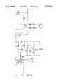
- FIG. 10is a top level schematic diagram of the modem controller and modem module in a preferred embodiment
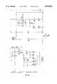
- FIG. 11is a detailed schematic diagram of a preferred modem module implemented by an AT&T V.32 data pump chip set
- FIG. 12is a schematic diagram of a preferred data access arrangement (DAA).
- FIG. 13is a top level schematic diagram of a preferred LAN/modem adapter.
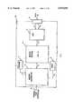
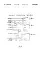
- FIG. 1depicts a block diagram of a preferred modem adapter 10 in accordance with the present invention useful for connecting a personal computer, e.g., IBM and compatible personal computers (PCs), to a public switched telephone network (PSTN), sometimes referred to as a wide area network (WAN).
- a personal computere.g., IBM and compatible personal computers (PCs)
- PSTNpublic switched telephone network
- WANwide area network
- Such a personal computeris typically controlled by an internal microprocessor (e.g., an Intel 80x86) and has an externally accessible parallel port (e.g., standard or "Centronics”) interfaced to the PC via its internal bus.
- an internal microprocessore.g., an Intel 80x86
- an externally accessible parallel porte.g., standard or "Centronics
- the modem adapter 10may appropriately be considered as being primarily comprised of three functional portions; i.e., a parallel port interface 12, a parallel port controller 14, and a modem control and interface 16.
- the parallel port interface 12is coupled to a parallel port connector 18 physically and electrically configured to interface to a female connector of a standard PC parallel port 20 on PC 22.
- the parallel port controller 14is coupled to the parallel port interface 12 and functions to bidirectionally transfer data to the standard PC parallel port 20.
- the parallel port controller 14is also coupled to the modem control and interface 16 to bidirectionally transfer data therewith.
- the interfacemodulates data sent to and demodulated data received from the PSTN (typically according to CCITT defined specifications) preferably via an RJ-11 connector 24 which is coupled to the PSTN 26.
- the function and operation of the parallel port controller 14 in coordination with the parallel port interface 12 for use with a standard PC parallel portis described in the aforementioned parent application 08/117,990.
- the physical interface between parallel port connectors 18, 20is comprised of eight-bit data path 28, a four-bit control path 30 and a five-bit status path 32.
- the definition of the standard signals found the 25-pin standard PC parallel port 20is found in Table 1.
- the parallel port controller 14is preferably capable of interfacing to different types of standard PC parallel ports, e.g., PC-XT, PC-AT, PS/2.
- PC-XTthe data path 28 is typically unidirectional and the status lines 32 are used to transfer data into the standard PC parallel port 20.
- the PC-AT and PS/2 portstypically permit bidirectional data transfer.
- the controller 14is preferably implemented with programmable logic, e.g., a field programmable gate array (FPGA) (not shown) which is loaded by a software device driver executed by the PC 22 to optimize its configuration for the particular parallel port type being used.
- FPGAfield programmable gate array
- the controller 14preferably supports other parallel port configurations, e.g., an enhanced parallel port or EPP as described in the Mar. 17, 1992 Release 1.7 to the IEEE P1284 Working Group that redefines the use of the pins on a parallel port.
- EPPenhanced parallel port
- a data strobe on pin 14(formerly auto feed) and a write signal on pin 1 (formerly strobe) are automatically generated by EPP hardware during an output instruction. This state remains until the device connected to the parallel port returns a wait signal on pin 11 (formerly busy).
- an input instruction to an EPPautomatically generates only a data strobe on pin 14 to signal the device connected to the parallel port to place data on the bidirectional data bus. The device then signals that the data is available with the wait signal on pin 11.
- embodiments of the present inventioncan transfer data across the parallel port at rates approaching that possible with a standard internal adapter card.
- the modem control and interface 16is primarily comprised of a modem controller 34, a modem module 36, and a data access arrangement (DAA) 38.
- DAAdata access arrangement
- Devices which form the modem module 36are readily available as integrated circuit chips and are sold as modem chip sets by various semiconductor manufacturers. Although functionally similar overall, chip sets by different manufacturers may require different divisions within the modem and control interface 16.
- the modem controller 34functions to control the transfer of all data between the standard PC parallel port 20 and the PSTN 26 according to standard protocols including the Hayes and Microcom command sets.
- the modem controller 34is coupled to the parallel port controller 14, using address/data/control bus 40, which functions as a PC interface for bidirectionally communicating data and commands to the PC 22 via the parallel port controller 14.
- the parallel port controller 14contains the registers shown in Table 3 for facilitating the transfer of data between the standard PC parallel port 20 and the modem controller 34.
- the PC 22transfers data to the modem adapter, the PC 22 first loads one of these registers and the modem controller 34 then accesses the data from the controller 14 register. Similarly when the modem controller 34 transfer data to the PC 22, these controller 14 registers are used. To output to one of these registers, the PC must first address the particular desired register. This task is done by placing the address of the register, e.g., F0, on data bits 0-7 and strobing the RAS (register address strobe), the auto feed control in the standard parallel port configuration.
- the registere.g., F0
- RASregister address strobe
- a subsequent strobe on the RDS(register data strobe), the strobe in the standard parallel port configuration, will output data bits 0-7 to the selected register.
- data bit 2is ORed with the register address when the register is selected.
- selecting register F0 for a subsequent readis done using address F4 (F0 OR 4).
- the modem controller 34is bidirectionally coupled via path 42 to a serial EEPROM 44, which stores modem configuration data, and via address/data bus 48 to an SRAM 46, which as a local memory stores modem data and program code.
- the SRAM 46is downloaded with a plurality of executable instructions that the modem controller 34 subsequently executes. More particularly, following the downloading of the parallel port controller FPGA 14, the modem controller, e.g., an MC68302, fetches two initial memory addresses (32-bits each), one byte at a time from a fixed address, e.g., 0, in response to a start signal, e.g., a processor reset.
- These two initial addressescorrespond to a start address which points to the start of a first bootstrap program and a stack pointer.
- no local memoryis associated with either these initial memory addresses or the first bootstrap program.
- the parallel port controller 14intercepts memory access strobes from the modem controller 34, requests the initial addresses from the PC 22 via the standard PC parallel port 20 and supplies these addresses to the modem controller 34. Then starting at the start address, the parallel port controller 14 fetches instructions from the PC 22, one byte at a time, which are executed by the modem controller 34.
- the access rate for this first bootstrap programis relatively slow, requiring wait states.
- this first bootstrap programdownloads a second bootstrap program into the SRAM 46, preferably at an address range distinct from that used by the first bootstrap program.
- the parallel port controlleris configured in response to instructions in the first bootstrap program, e.g., a JUMP or an I/O, to permit the modem controller to begin executing the second bootstrap program from the SRAM 46.
- the second bootstrap programthen downloads a third program, the modem control software, from the PC 22 into the SRAM 46 and transfers control to the modem control software within another portion of the SRAM 46 via a JUMP instruction.
- modem control softwareis initially stored on the PC 22, normally on a hard or floppy disk, and transferred to the modem controller 34 without requiring any resident non-volatile, unalterable memory, e.g., ROM. Consequently, any enhancements or modifications to the modem control software do not require alterations to hardware that embodies a modem adapter of the present invention.
- a preferred embodimentcomprises the following steps: (1) Initialize the modem controller 34 to begin fetching instructions and data, which correspond to a first bootstrap program, from the PC 22 via the standard PC parallel port 20; (2) Load, under control of the first bootstrap program, the data received from the PC 22, which correspond to a second bootstrap program, into the SRAM 46 used as local memory, (3) Execute the second bootstrap program with the modem controller 34 to receive data from the PC 22, (4) Load, under control of the second bootstrap program, the data received from the PC 22 corresponding to a third program, the modem control software, into the local memory, and (5) Execute the modem control software with the modem controller 34.
- CMOScomplementary metal-oxide-semiconductor
- SRAMstatic random access memory
- DRAMdynamic random access memory
- NVRAMnonvolatile, but alterable, i.e., read/write, memory devices
- Such devicesmay be periodically reloaded whenever a new version of software is available.
- Typical types of nonvolatile but alterable memory devicesinclude Flash, EEPROM, battery backed-up RAM and CORE as well as any other functionally compatible devices, i.e., devices which maintain memory when power is removed but are otherwise alterable under program control. It is further recognized that a memory system containing portions of memory comprised of volatile devices and other portions comprised of non-volatile but alterable devices is useful with the described bootstrap method when the non-volatile devices are downloaded with software or configuration data.
- the modem controller program executiontakes place across the standard PC parallel port.
- various interfacescan be used in place of the standard PC parallel port for practicing the present invention. For example, downloading of data using the aforementioned bootstrap method via a standard serial port, via an I/O port, or via a shared memory are also within the scope of the present invention.
- a modem adapterhas been described as a preferred embodiment, the scope of the present invention includes other types of adapters can profitably use the described bootstrap method for downloading executable instructions to either volatile or nonvolatile memories.
- a LAN/modem adapteris further described below.
- adapterse.g., tape controllers, SCSI controllers, Ethernet adapters, pagers, communication equipment, test equipment, LAN adapters, etc., can be reconfigured with new operating software as dictated by the application.
- the modem module 36is bidirectionally coupled to the modem controller 34 using digital signal path 50 as well as to the DAA 38, using preconditioned analog signal path 52.
- the DAA 38is coupled using ring path 54 and tip path 56 to an RJ-11 connector 24 which is coupled to the PSTN 26.
- the DAA 38preconditions signals to and from the PSTN 26 as well as providing signal protection, required when connecting to various PSTNs, to form preconditioned analog signals on path 52.
- the preconditioned analog signalsare bidirectionally input to the modem module 36 which converts these analog signals into digital form on digital signal path 50 for protocol processing by the modem controller 34.
- Digital signal path 50consists of two interfaces that the modem controller 34 uses to communicate with the modem module 36.
- the first interfacecommunicates in parallel to the modem controller 34 eight bits at time.
- the modem controller 34uses the parallel interface to control and interrogate the status of the modem module 36.
- the second interfaceis a serial interface.
- the serial interfaceis comprised of a first full duplex USART (universal synchronous/asynchronous receive/transmitter) integrally located with the modem controller 34 and a second full duplex USART within the modem module 36.
- the serial interfaceis used to exchange data that is received from or transmitted to the public switched telephone network (PSTN) 26.
- PSTNpublic switched telephone network
- FIGS. 10-12there are shown schematic diagrams of a preferred embodiment of the present invention.
- FIG. 10a top level schematic diagram showing the interface between a 68302 microprocessor, the modem controller 34, and a data pump section which is the modem module 36 for a preferred embodiment.
- FIG. 11a detailed schematic diagram of the data pump section/modem module is shown.
- the modem module 36is formed with an AT&T V.32 chip set. This chip set is comprised of a data pump interface, a digital signal processor (DSP) and a codec. This chip set is coupled to a DAA 38, as found in FIG. 12.
- DSPdigital signal processor
- the three components of the data pump chip sectiontogether perform the function of turning the binary data into an analog signal that can be transmitted on the PSTN.
- the data pump interfacefunctions to connect the DSP to the modem controller 50. This involves adapting signal timing and bus isolation for each of the two smart devices.
- the DSPis the digital signal processor that actually perform mathematical manipulations of data such that it is in a format that is compatible with an a analog PSTN line.
- the codecdoes digital to analog and analog to conversions of modulated data as well as signal amplification and echo cancelling allowing the received signal to be interpreted separately while on the same line as the transmitted signal.
- redirector software 58The redirector software's function is to permit the use of existing modem control software to transparently work with the modem adapter 10 of the present invention.
- Existing modem control softwaree.g., CROSSTALK, PROCOMM, MIRROR, etc.
- CROSSTALKCROSSTALK
- PROCOMMPROCOMM
- MIRRORMIRROR
- the serial I/O chipreferred to as a UART or universal asynchronous receiver transmitter, or a USART is the interface between the PC and a modem or serial RS-232 link.
- These communication I/O ports in a PCare referred to as COM1, COM2, COM3 and COM4 where the first two ports are located at default address blocks beginning at 0x3F8 and 0x2F8, respectively.
- the modem adapter 10is instead interfaced to the standard PC parallel port 20 on the PC 22 at a specified, but different, I/O location.
- These standard PC parallel portsare referred to as LPT1, LPT2 and LPT3 where the first two ports are typically located at default address blocks starting at 0x378 and 0x278, respectively.
- the redirector software 58intercepts serial I/O port commands and instead outputs reformatted parallel port commands to the modem adapter 10 to permit the transparent use of the existing modem control software. Due to the mode of operation for the microprocessor required by the redirector software 58, this task cannot be accomplished on all compatible PCs but instead can only be accomplished on PCs with a 386 or later generation processor as its microprocessor controller. Thus, the 386, 486, Pentium, future compatible processors and equivalents support the use of the redirector software 58 while PCs based upon the 86, 186 and 286 or equivalent microprocessors cannot be supported.
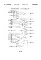
- FIG. 3a block diagram is shown of the redirector software 58.
- An IBM PC or equivalent microcomputer 60under control of a microprocessor 62, executes software packages 64 that are normally launched and at least partially under control of the MS-DOS operating system.
- the software package 64is modem control software
- the software package 64will contain software instructions 66 that either directly output I/O commands to a designated 8250 serial I/O port or alternatively rely upon resident software routines from the BIOS (not shown), a ROM within the PC, that instead contains the I/O commands to be intercepted. From the standpoint of the redirector software 58, the actual source of the serial I/O instruction is irrelevant.
- the redirector software 58determines if an I/O instruction references an I/O port within a designated range, as shown in Block 68. If the I/O instruction is outside of the designated range, the redirector software 58 passes the I/O instruction, as shown in Block 70. However, if an I/O instruction for the designated UART is detected, the redirector software 58 will reformat the instruction into an equivalent form for the modem adapter 10 and instead output this command to the designated standard PC parallel port 20, as shown in Block 72.
- modem control softwarecan be made that directly supports the parallel port interface to a modem that is found in embodiments of the present invention, the vast majority of existing software only a conventional serial port interface. While software that directly supports the parallel port interface inherently is more efficient due to the reduced software overhead, the use of the redirector software 58 permits the use of extensive libraries of existing modem control software.
- a modem driveris initially loaded which configures the modem adapter 10 of the present invention as previously described by first downloading configuration data for the parallel port controller 14 and then presenting executable code to the modem controller 34 that is executed to download the remaining modem control software. Additionally in an alternative embodiment, a driver is installed for a LAN interface. Next, the redirector software 58 is similarly executed.
- Block 74the redirector software 58 in Block 74 must confirm that a proper environment is available for the redirector software 58, that being the existence of a microprocessor that is a 386 or later generation of the 80 ⁇ 86 family of microprocessors and that a conflicting memory manager is not present. Thus, the use of an XT (86) or a 286 type AT PC will result in a failure. In these cases, the redirector software 58 will exit to Block 76 and will not be installed.
- Block 78which binds to the preloaded modem driver and LAN driver, when present. The binding process makes routines for interfacing to the modem control and interface 16 and, when present, LAN control and interface accessible to the redirector software 58. A failure of this initialization is noted at Block 80.
- Data structuresare then initialized in Block 82, for switching the 386 or later generation 80x86 microprocessor into protected mode and then into virtual or v86 mode where designated ranges of I/O instructions which refer to the designated serial I/O port can be trapped.
- the default range of I/O instructionsis from 0x3F8-0x3FF
- the default range of I/O instructionsis from 0x2F8-0x2FF.
- the redirector software 58may be configured to work with other than the default I/O ranges.
- an I/O permission bitmapis generated for the current task segment to identify the I/O instructions to be trapped.
- the microprocessor 62is then switched in Block 84 into protected mode and then into v86 mode.
- the redirector software 58terminates but remains resident in memory, returning control to MS-DOS which will now be running in v86 mode rather than real mode. Consequentially, all I/O instruction to the designated address ranges will be trapped and redirected to the modem adapter 10.
- the initialized hardware in the microprocessor 62running in v86 mode, will trap any I/O instructions within the designated range and cause an interrupt, specifically to interrupt 13, as defined by the 80x86 microprocessor's hardware. This interrupt is directed toward a redirector interrupt routine which is now resident in memory.
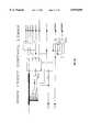
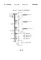
- FIG. 5A-5Dtypical examples of the processing of the redirection software 58 are given.
- an OUT instruction within the specified I/O rangeis intercepted by the microprocessor 62.
- the microprocessor 62then generates an interrupt to the redirector software 58.
- the redirector software 58identifies this type of output command as a send data command and subsequently reformats this command into a parallel port compatible send data command for the modem adapter 10. The reformatted command is then sent to the designated standard PC parallel port.
- the redirector software 58intercepts an IN instruction that is used to receive data from the USART.
- an IN instructionis instead identified as a request for status from the USART. Since the actual hardware associated with the modem of the present invention differs significantly from a UART-modem combination as found in the prior art, the redirector software 58 will reformat the status data into a form compatible with the UART status of the prior art, thus achieving transparent operation while interfacing to the modem adapter 10 of the present invention.
- FIG. 5Can IN instruction is instead identified as a request for status from the USART. Since the actual hardware associated with the modem of the present invention differs significantly from a UART-modem combination as found in the prior art, the redirector software 58 will reformat the status data into a form compatible with the UART status of the prior art, thus achieving transparent operation while interfacing to the modem adapter 10 of the present invention. In FIG.
- an OUT instruction directed to the USART control portis intercepted by the redirector software 58 and translated into a command to the modem control and interface 16.
- Appendix A of the parent applicationwhich is incorporated by reference is a software listing of the redirector software 58 configured for operation with MS-DOS 6.0, illustrating the features that have been described.
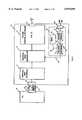
- a LAN control and interface 86is additionally included within the modem adapter to form a LAN/modem adapter 10.
- the interface of a LAN or network adapter to a standard PC parallel porthas already been disclosed in a commonly assigned patent.
- selection logicis included within the parallel port controller 14 to alternatively interface to either the modem control and interface 16 or the LAN control and interface 86, thus sharing the standard PC parallel port 20.
- the PC 22communicates with the modem control and interface via registers located within the parallel port controller at addresses within the range of F0 to F3 (ORed with 04 for data reads).
- the LAN control and interface 86is instead addressed when the most significant nibble of the address is not an F, e.g., the most significant nibble equals O-E.
- a single data bitis used to distinguish reads and writes to registers associated with the LAN control and interface 86.
- the read/write determinationis done within the LAN control and interface 86 using data bit 6.
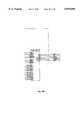
- FIG. 7there is shown a block diagram of logic used in a preferred embodiment of selection logic contained within the parallel port controller 14 comprised of a multiplexor 88 and an AND gate 90.
- the AND gate 90ANDs data bits 0-7 to determine whether or not a register access is directed to the modem control and interface 16 by recognizing addresses of Fx. This signal is used as a select signal to the multiplexor 88.
- the multiplexor 88selectively passes the RDS and the RAS dependent upon the select input generated by AND gate 90. Additionally, a read/write signal is generated according to the selected register address for the modem control and interface 16 or the LAN control and interface 86.
- Schematic diagrams of the logic associated with a preferred embodiment as implemented within a FPGAare shown in FIGS. 8A-8I.
- the LAN control and interface 86is also capable of transferring data without continuous control from the PC 22.
- the selection logiconly permits the PC to communicate with either the modem control and interface 16 or the LAN control and interface 86 during each I/O operation, the other interface can concurrently communicate using local control.
- simultaneous communications with a WAN and a LANare possible with embodiments of the present invention.
- the LAN control and interface 86is comprised of three main portions, a LAN controller 92, an SRAM 94 and a LAN interface 96.
- the LAN controller 92is coupled to the parallel port controller 14 via a data/control path 98 that functions as a PC interface to bidirectionally transfer data to the standard PC parallel port 20.
- the SRAM 94coupled to the LAN controller 92 using path 100, temporarily stores packets of data that are transferred across a network 102, commonly referred to as a local area network (LAN).
- the LAN interface 96is coupled to the LAN controller 92 using path 104 and conditions network data according to IEEE 802 to the LAN 102 through a connector 108.
- Connector 108is coupled to the LAN interface 96 using path 106.
- Connector 108may be either a BNC connector or a RJ-45 modular plug, depending upon the mode of operation required.
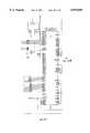
- FIG. 13there is shown a detailed schematic diagram of a preferred embodiment of a LAN/modem adapter.
- a DB25 parallel port connectoris coupled to a bidirectional buffer U3 and unidirectional buffer U4 which form the parallel port interface 12.
- a field programmable gate array (FPGA), U8forms the parallel port controller 14 which controls both the interface to the parallel port and the selection/port sharing logic for the modem section (modem control and interface 16) and the LAN section (LAN control and interface 86).
- FPGAfield programmable gate array
- the modem adapter 10is comprised of a substantially enclosed rounded rectangular housing 110.
- the parallel port connector 18is mounted on one end of the housing 110 for mating connection to the standard PC parallel port 20.
- the parallel port connector 18is a 25-pin, male, D-shell connector which mates to a complementary female connector as found on the standard PC parallel port 20 of a personal computer (PC).
- First and second captive screws 112 and 114are mounted in the housing 110 for coupling to threaded holes typically provided adjacent to a standard PC parallel port connector.
- a tractor belt 116is mounted for rotation within a recess around the circumference of the housing 110 and coupled to screws 112 and 114 to enable a user to cooperatively rotate the screws 112 and 114.
- the RJ-11 connector 24is mounted on the opposite end of the housing 110 and is configured to connect the modem adapter 10 to a public switched telephone network (PSTN).
- Connector 108is also mounted on the opposite end of the housing 110.
- Connector 108is configured to connect to a local area network media, e.g., an unshielded twisted pair Ethernet network using an RJ-45 connector.
- connector 108is a BNC connector (not shown) for connecting to a coaxial cable as is used in standard Ethernet networks.
- the housing 110additionally includes a socket 118 intended to receive a conventional AC adapter jack which supplies a DC voltage (e.g., 12 volt D.C. unregulated or 5 volt D.C. regulated) for providing power to the modem.
- a DC voltagee.g., 12 volt D.C. unregulated or 5 volt D.C. regulated
- the rectangular housing 110is preferably dimensioned to be substantially pocket sized so that it can be conveniently carried by a user.
- the modem adapter 10 in accordance with the present invention currently being manufactured by the assignee of the present applicationhas a length equal to approximately 41/2 inches, a width equal to approximately 21/2 inches, and a height equal to approximately 1 inch.
- the modem adapter 10is intended to readily connect externally to any standard PC parallel port, thus eliminating the difficulties with prior art circuit board modems.
- the external configuration of the modem 10, as depicted in FIGS. 9A, 9B and 9Cmakes it particularly suitable for use with laptop computers and also for PCs in which the available slots, or power, are at a premium.
Landscapes
- Engineering & Computer Science (AREA)
- Theoretical Computer Science (AREA)
- Software Systems (AREA)
- Computer Networks & Wireless Communication (AREA)
- Signal Processing (AREA)
- Physics & Mathematics (AREA)
- General Engineering & Computer Science (AREA)
- General Physics & Mathematics (AREA)
- Computer Security & Cryptography (AREA)
- Communication Control (AREA)
Abstract
Description
TABLE 1______________________________________DB-25 Pin Definition Type______________________________________ 1 strobe control,RDS 2data bit 0data 3data bit 1data 4data bit 2data 5data bit 3data 6data bit 4data 7data bit 5data 8data bit 6 data 9data bit 7data 10acknowledge status 11busy status 12paper end status 13select status 14 auto feed control,RAS 15fault status 16 initializeprinter control 17select input control 18ground 19ground 20ground 21ground 22ground 23ground 24 ground25 ground______________________________________
TABLE 2______________________________________Data Modulation CCITT V.32bis with trellis coding at 14400 bps, 12000 bps, 9600 bps and 7200 bps CCITT V.32bis at 4800 bps CCITT V.32 with trellis coding at 9600 bps CCITT V.32 at 4800 bps CCITT V.22bis at 2400 bps CCITT V.22 at 1200 bps Bell 212A at 1200 bpsError Control CCITT V.42 LAP-M MNP2, 3, and 4Data Compression CCITT V.42bis MNP Class Class 5Fax modulation Group 3 send/receive fax communication under the control ofClass 1 orClass 2 software, using: CCITT v.17 at 14400 bps, 12000 bps, 9600 bps, 7200 bps, and 4800 bps CCITT v.29 at 9600 bps, 7200 bps, and 4800 bps CCITT V.27ter at 4800 bps and 2400 bps______________________________________
TABLE 3______________________________________Register Address Host Modem Description______________________________________Host Data F0 Write Read Data output to modemHost Data F0 Read Write Data output to hostHost Command F1 Write Read Software Command/ StatusModem Command F1 Read Write Software Command/ StatusHost Control F2 Write -- Host IRQ output controlModem Control F2 -- Write Modem IRQ output controlHost Status F3 -- Read Hardware statusModem Status F3 Read Write Hardware status______________________________________
Claims (46)
Priority Applications (2)
| Application Number | Priority Date | Filing Date | Title |
|---|---|---|---|
| US08/339,408US5870609A (en) | 1993-12-17 | 1994-11-14 | Technique for bootstrapping executable code to an adapter |
| US09/235,924US6141706A (en) | 1993-12-17 | 1999-01-22 | Communication method for redirecting information to another port |
Applications Claiming Priority (2)
| Application Number | Priority Date | Filing Date | Title |
|---|---|---|---|
| US08/170,088US5408614A (en) | 1993-12-17 | 1993-12-17 | Modem adapter for use with standard PC parallel port |
| US08/339,408US5870609A (en) | 1993-12-17 | 1994-11-14 | Technique for bootstrapping executable code to an adapter |
Related Parent Applications (1)
| Application Number | Title | Priority Date | Filing Date |
|---|---|---|---|
| US08/170,088Continuation-In-PartUS5408614A (en) | 1993-12-17 | 1993-12-17 | Modem adapter for use with standard PC parallel port |
Related Child Applications (1)
| Application Number | Title | Priority Date | Filing Date |
|---|---|---|---|
| US09/235,924DivisionUS6141706A (en) | 1993-12-17 | 1999-01-22 | Communication method for redirecting information to another port |
Publications (1)
| Publication Number | Publication Date |
|---|---|
| US5870609Atrue US5870609A (en) | 1999-02-09 |
Family
ID=26865687
Family Applications (2)
| Application Number | Title | Priority Date | Filing Date |
|---|---|---|---|
| US08/339,408Expired - Fee RelatedUS5870609A (en) | 1993-12-17 | 1994-11-14 | Technique for bootstrapping executable code to an adapter |
| US09/235,924Expired - Fee RelatedUS6141706A (en) | 1993-12-17 | 1999-01-22 | Communication method for redirecting information to another port |
Family Applications After (1)
| Application Number | Title | Priority Date | Filing Date |
|---|---|---|---|
| US09/235,924Expired - Fee RelatedUS6141706A (en) | 1993-12-17 | 1999-01-22 | Communication method for redirecting information to another port |
Country Status (1)
| Country | Link |
|---|---|
| US (2) | US5870609A (en) |
Cited By (11)
| Publication number | Priority date | Publication date | Assignee | Title |
|---|---|---|---|---|
| US6442625B1 (en)* | 1997-04-25 | 2002-08-27 | Simpletech, Inc. | Multi-function module incorporating flash memory and enhanced I/O interface that can translate data from one format into another format for subsequent transmission to an external device |
| US6457175B1 (en)* | 1998-11-09 | 2002-09-24 | Tut Systems, Inc. | Method and apparatus for installing a software upgrade within a memory resource associated with a computer system |
| US6473899B1 (en)* | 1996-08-28 | 2002-10-29 | Extended Systems, Inc. | Field configurable embedded computer system |
| US6631520B1 (en)* | 1999-05-14 | 2003-10-07 | Xilinx, Inc. | Method and apparatus for changing execution code for a microcontroller on an FPGA interface device |
| US6665752B1 (en)* | 2000-02-17 | 2003-12-16 | Conexant Systems, Inc. | Interrupt driven interface coupling a programmable media access controller and a process controller |
| US6795965B1 (en)* | 2000-05-10 | 2004-09-21 | Microsoft Corporation | Multi-source program module updater |
| US20050137822A1 (en)* | 2003-12-23 | 2005-06-23 | Burch Jefferson B. | Configurable measurement interface |
| US20080201704A1 (en)* | 2007-02-19 | 2008-08-21 | Kabushiki Kaisha Toshiba | Office equipment and program installation support method |
| US20110126190A1 (en)* | 2009-11-23 | 2011-05-26 | Julian Michael Urbach | Stream-Based Software Application Delivery and Launching System |
| US20140137166A1 (en)* | 2000-10-03 | 2014-05-15 | At&T Intellectual Property Ii, Lp | Intra-premises wireless broadband service using lumped and distributed wireless radiation from cable source input |
| US10114660B2 (en) | 2011-02-22 | 2018-10-30 | Julian Michael Urbach | Software application delivery and launching system |
Families Citing this family (14)
| Publication number | Priority date | Publication date | Assignee | Title |
|---|---|---|---|---|
| US6711205B1 (en) | 1998-09-25 | 2004-03-23 | Intel Corporation | Tone detector for use in a modem |
| US6711206B1 (en)* | 1998-09-25 | 2004-03-23 | Intel Corporation | Modem using a digital signal processor and separate transmit and receive sequencers |
| US6661848B1 (en) | 1998-09-25 | 2003-12-09 | Intel Corporation | Integrated audio and modem device |
| US6760784B1 (en)* | 1998-10-08 | 2004-07-06 | International Business Machines Corporation | Generic virtual device driver |
| US6903434B2 (en)* | 1999-05-20 | 2005-06-07 | Alliance Semiconductors | Method and apparatus for integrating flash EPROM and SRAM cells on a common substrate |
| JP2003131956A (en)* | 2001-10-25 | 2003-05-09 | Fuji Xerox Co Ltd | Device control system |
| US7089549B2 (en)* | 2002-04-01 | 2006-08-08 | International Business Machines Corp. | Updating flash memory |
| US7660910B2 (en)* | 2004-08-30 | 2010-02-09 | Lantronix, Inc. | Secure communication port redirector |
| US8170604B2 (en)* | 2006-06-27 | 2012-05-01 | Motorola Mobility, Inc. | Method and system for managing communications for a multi-mode communications device |
| US8665778B2 (en) | 2006-11-30 | 2014-03-04 | Motorola Mobility Llc | Monitoring and control of transmit power in a multi-modem wireless communication device |
| US8059702B2 (en)* | 2006-11-30 | 2011-11-15 | Motorola Mobility, Inc. | Monitoring multiple modem transmission in a communication device |
| US8744519B2 (en)* | 2006-12-14 | 2014-06-03 | Motorola Mobility Llc | Multimodal phone data session management enhancement that alleviates dual transmission problems |
| US8195250B2 (en)* | 2008-04-30 | 2012-06-05 | Motorola Mobility, Inc. | Method and apparatus for controlling power among modems in a multi-mode mobile communication device |
| US9542196B2 (en)* | 2014-02-28 | 2017-01-10 | Intel Corporation | Communication terminal and method for providing configuration data for a modem with system boot firmware |
Citations (8)
| Publication number | Priority date | Publication date | Assignee | Title |
|---|---|---|---|---|
| US5202963A (en)* | 1990-12-18 | 1993-04-13 | Bull Hn Information Systems Inc. | Method and apparatus for adapting a remote communications controller to a variety of types of communications modems |
| US5237690A (en)* | 1990-07-06 | 1993-08-17 | International Business Machines Corporation | System for testing adaptor card upon power up and having disablement, enablement, and reconfiguration options |
| US5249218A (en)* | 1992-04-06 | 1993-09-28 | Spectrum Information Technologies, Inc. | Programmable universal interface system |
| US5412798A (en)* | 1991-12-27 | 1995-05-02 | Intel Corporation | System for enabling access to device driver residing in resource memory corresponding to coupled resource by allowing memory mapping to device driver to be executed |
| US5446898A (en)* | 1992-06-22 | 1995-08-29 | International Business Machines Corporation | Method and apparatus for configuring and installing a loadable ABIOS device support layer in a computer system |
| US5537607A (en)* | 1993-04-28 | 1996-07-16 | International Business Machines Corporation | Field programmable general purpose interface adapter for connecting peripheral devices within a computer system |
| US5623604A (en)* | 1992-11-18 | 1997-04-22 | Canon Information Systems, Inc. | Method and apparatus for remotely altering programmable firmware stored in an interactive network board coupled to a network peripheral |
| US5664231A (en)* | 1994-04-29 | 1997-09-02 | Tps Electronics | PCMCIA interface card for coupling input devices such as barcode scanning engines to personal digital assistants and palmtop computers |
Family Cites Families (13)
| Publication number | Priority date | Publication date | Assignee | Title |
|---|---|---|---|---|
| US4682352A (en)* | 1985-08-20 | 1987-07-21 | Cermetek Microelectronics, Inc. | Universal modem receiver transmitter |
| JPH0748779B2 (en)* | 1987-09-01 | 1995-05-24 | 株式会社村田製作所 | Modem device |
| US5033062A (en)* | 1989-05-30 | 1991-07-16 | Morrow Stephen E | Digital modem |
| EP0524199B1 (en)* | 1990-03-02 | 2000-06-14 | REMION, Michel J. | Telecommunication interface apparatus and method |
| US5299314A (en)* | 1990-03-22 | 1994-03-29 | Xircom, Inc. | Network adapter using status inlines and data lines for bi-directionally transferring data between lan and standard p.c. parallel port |
| US5276443A (en)* | 1991-03-27 | 1994-01-04 | Xircom, Inc. | Parallel port multiplexor for PC parallel port |
| US5202899A (en)* | 1991-08-16 | 1993-04-13 | Rockwell International Corporation | Apparatus for providing dynamic selection of modem protocol to support multiple modem types |
| AU4802093A (en)* | 1992-08-10 | 1994-03-03 | Advanced Logic Research, Inc. | Computer interface for concurrently performing plural seeks on plural disk drives |
| JPH06103213A (en)* | 1992-09-18 | 1994-04-15 | Hitachi Ltd | Input/output device |
| US5546543A (en)* | 1993-03-26 | 1996-08-13 | Digital Equipment Corporation | Method for assigning priority to receive and transmit requests in response to occupancy of receive and transmit buffers when transmission and reception are in progress |
| US5630061A (en)* | 1993-04-19 | 1997-05-13 | International Business Machines Corporation | System for enabling first computer to communicate over switched network with second computer located within LAN by using media access control driver in different modes |
| US5410754A (en)* | 1993-07-22 | 1995-04-25 | Minute Makers, Inc. | Bi-directional wire-line to local area network interface and method |
| US5408614A (en)* | 1993-12-17 | 1995-04-18 | Xircom, Inc. | Modem adapter for use with standard PC parallel port |
- 1994
- 1994-11-14USUS08/339,408patent/US5870609A/ennot_activeExpired - Fee Related
- 1999
- 1999-01-22USUS09/235,924patent/US6141706A/ennot_activeExpired - Fee Related
Patent Citations (9)
| Publication number | Priority date | Publication date | Assignee | Title |
|---|---|---|---|---|
| US5237690A (en)* | 1990-07-06 | 1993-08-17 | International Business Machines Corporation | System for testing adaptor card upon power up and having disablement, enablement, and reconfiguration options |
| US5202963A (en)* | 1990-12-18 | 1993-04-13 | Bull Hn Information Systems Inc. | Method and apparatus for adapting a remote communications controller to a variety of types of communications modems |
| US5412798A (en)* | 1991-12-27 | 1995-05-02 | Intel Corporation | System for enabling access to device driver residing in resource memory corresponding to coupled resource by allowing memory mapping to device driver to be executed |
| US5249218A (en)* | 1992-04-06 | 1993-09-28 | Spectrum Information Technologies, Inc. | Programmable universal interface system |
| US5367563A (en)* | 1992-04-06 | 1994-11-22 | Spectrum Information Technologies, Inc. | Programmable universal modem system and method for using the same |
| US5446898A (en)* | 1992-06-22 | 1995-08-29 | International Business Machines Corporation | Method and apparatus for configuring and installing a loadable ABIOS device support layer in a computer system |
| US5623604A (en)* | 1992-11-18 | 1997-04-22 | Canon Information Systems, Inc. | Method and apparatus for remotely altering programmable firmware stored in an interactive network board coupled to a network peripheral |
| US5537607A (en)* | 1993-04-28 | 1996-07-16 | International Business Machines Corporation | Field programmable general purpose interface adapter for connecting peripheral devices within a computer system |
| US5664231A (en)* | 1994-04-29 | 1997-09-02 | Tps Electronics | PCMCIA interface card for coupling input devices such as barcode scanning engines to personal digital assistants and palmtop computers |
Cited By (26)
| Publication number | Priority date | Publication date | Assignee | Title |
|---|---|---|---|---|
| US6473899B1 (en)* | 1996-08-28 | 2002-10-29 | Extended Systems, Inc. | Field configurable embedded computer system |
| US6442625B1 (en)* | 1997-04-25 | 2002-08-27 | Simpletech, Inc. | Multi-function module incorporating flash memory and enhanced I/O interface that can translate data from one format into another format for subsequent transmission to an external device |
| US6728794B2 (en) | 1997-04-25 | 2004-04-27 | Simple Tech, Inc. | Multi-function module incorporating flash memory and enhanced I/O interface that can translate data from one format into another format for subsequent transmission to an external device |
| US20040199675A1 (en)* | 1997-04-25 | 2004-10-07 | Simpletech, Inc. | Multi-function interface module |
| US6981071B2 (en) | 1997-04-25 | 2005-12-27 | Simpletech, Inc. | Multi-function interface module |
| US6457175B1 (en)* | 1998-11-09 | 2002-09-24 | Tut Systems, Inc. | Method and apparatus for installing a software upgrade within a memory resource associated with a computer system |
| US6631520B1 (en)* | 1999-05-14 | 2003-10-07 | Xilinx, Inc. | Method and apparatus for changing execution code for a microcontroller on an FPGA interface device |
| US6665752B1 (en)* | 2000-02-17 | 2003-12-16 | Conexant Systems, Inc. | Interrupt driven interface coupling a programmable media access controller and a process controller |
| US6795965B1 (en)* | 2000-05-10 | 2004-09-21 | Microsoft Corporation | Multi-source program module updater |
| US10080040B2 (en) | 2000-10-03 | 2018-09-18 | At&T Intellectual Property Ii, L.P. | Intra-premises wireless broadband service using lumped and distributed wireless radiation from cable source input |
| US9264741B2 (en)* | 2000-10-03 | 2016-02-16 | At&T Intellectual Property Ii, Lp | Intra-premises wireless broadband service using lumped and distributed wireless radiation from cable source input |
| US20140137166A1 (en)* | 2000-10-03 | 2014-05-15 | At&T Intellectual Property Ii, Lp | Intra-premises wireless broadband service using lumped and distributed wireless radiation from cable source input |
| DE102004036784B4 (en)* | 2003-12-23 | 2007-01-25 | Agilent Technologies, Inc. (n.d.Ges.d.Staates Delaware), Palo Alto | Measuring device, interface method for a measuring device and input system for a measuring device |
| GB2409740B (en)* | 2003-12-23 | 2007-01-17 | Agilent Technologies Inc | A measurement interface |
| US7437486B2 (en) | 2003-12-23 | 2008-10-14 | Agilent Technologies, Inc. | Configurable measurement interface coupled to a front-end subsystem and a back-end subsystem for receiving a set of bootstrap information |
| US20050137822A1 (en)* | 2003-12-23 | 2005-06-23 | Burch Jefferson B. | Configurable measurement interface |
| GB2409740A (en)* | 2003-12-23 | 2005-07-06 | Agilent Technologies Inc | A measurement interface for transferring bootstrap information |
| CN100375071C (en)* | 2003-12-23 | 2008-03-12 | 安捷伦科技有限公司 | Configurable measurement interface |
| US20080201704A1 (en)* | 2007-02-19 | 2008-08-21 | Kabushiki Kaisha Toshiba | Office equipment and program installation support method |
| US7996831B2 (en)* | 2007-02-19 | 2011-08-09 | Kabushiki Kaisha Toshiba | Office equipment and program installation support method |
| US20140047435A1 (en)* | 2009-11-23 | 2014-02-13 | Julian Michael Urbach | Stream-based software application delivery and launching system |
| US9009700B2 (en)* | 2009-11-23 | 2015-04-14 | Julian Michael Urbach | Stream-based software application delivery and launching system |
| US9195449B1 (en)* | 2009-11-23 | 2015-11-24 | Julian Michael Urbach | Stream-based software application delivery and launching system |
| US8584120B2 (en)* | 2009-11-23 | 2013-11-12 | Julian Michael Urbach | Stream-based software application delivery and launching system |
| US20110126190A1 (en)* | 2009-11-23 | 2011-05-26 | Julian Michael Urbach | Stream-Based Software Application Delivery and Launching System |
| US10114660B2 (en) | 2011-02-22 | 2018-10-30 | Julian Michael Urbach | Software application delivery and launching system |
Also Published As
| Publication number | Publication date |
|---|---|
| US6141706A (en) | 2000-10-31 |
Similar Documents
| Publication | Publication Date | Title |
|---|---|---|
| US5870609A (en) | Technique for bootstrapping executable code to an adapter | |
| US5408614A (en) | Modem adapter for use with standard PC parallel port | |
| US6799225B2 (en) | Controllerless modem | |
| US5537558A (en) | Apparatus and method for communicating multiple devices through one PCMCIA interface | |
| US5548782A (en) | Apparatus for preventing transferring of data with peripheral device for period of time in response to connection or disconnection of the device with the apparatus | |
| US6389495B1 (en) | Dedicated circuit and method for enumerating and operating a peripheral device on a universal serial bus | |
| US5537654A (en) | System for PCMCIA peripheral to execute instructions from shared memory where the system reset signal causes switching between modes of operation by alerting the starting address | |
| US6704824B1 (en) | Universal serial bus adapter with automatic installation | |
| US5619659A (en) | System for extending ISA bus without using dedicated device driver software by using E2 P2 interface which provides multiplexed bus signal through standard parallel port connector | |
| US5983292A (en) | Message transport mechanisms and methods | |
| US4654821A (en) | Automatic restart apparatus for a processing system | |
| US6978319B1 (en) | Plug-and-play cable with protocol translation | |
| US5615344A (en) | Apparatus used to interface a peripheral device to a computer employing a reconfigurable interface circuit | |
| US5548730A (en) | Intelligent bus bridge for input/output subsystems in a computer system | |
| US6282643B1 (en) | Computer system having flash memory BIOS which can be accessed remotely while protected mode operating system is running | |
| US5842011A (en) | Generic remote boot for networked workstations by creating local bootable code image | |
| US5896534A (en) | Operating system independent apparatus and method for supporting input/output devices unsupported by executing programs | |
| US4590551A (en) | Memory control circuit for subsystem controller | |
| US5797031A (en) | Method and apparatus for peripheral device control by clients in plural memory addressing modes | |
| US6081856A (en) | Adapter and method for emulating the operation of a peripheral device of a computer | |
| US5590315A (en) | Method and apparatus for simulating user input device presence in a computer system | |
| US5638530A (en) | Direct memory access scheme using memory with an integrated processor having communication with external devices | |
| WO1983002020A1 (en) | Direct memory access for a data transfer network | |
| US5757639A (en) | Electronic apparatus | |
| US5809068A (en) | PCMCIA modem |
Legal Events
| Date | Code | Title | Description |
|---|---|---|---|
| AS | Assignment | Owner name:XIRCOM, INC., CALIFORNIA Free format text:ASSIGNMENT OF ASSIGNORS INTEREST;ASSIGNORS:THORNTON, TIMOTHY J.;ROSEN, ROBERT;HENDERSON, ERIC K.;REEL/FRAME:007253/0549;SIGNING DATES FROM 19941107 TO 19941109 | |
| AS | Assignment | Owner name:NATIONSBANK OF TEXAS, N.A., AS ADMINISTRATIVE LEND Free format text:FIRST AMENDMWENT TO INTELLECTUAL PROPERTY SECURITY AGREEMENT;ASSIGNOR:XIRCOM, INC.;REEL/FRAME:008958/0749 Effective date:19971230 | |
| AS | Assignment | Owner name:XIRCOM, INC., CALIFORNIA Free format text:CORRECTIVE ASSIGNMENT TO CHANGE THE ASSIGNEE AND THE ASSIGNOR, PREVIOUSLY RECORDED AT REEL 008952, FRAME 0749;ASSIGNOR:BANK OF AMERICA, N.A. F/K/A NATIONSBANS, N.A.;REEL/FRAME:010639/0827 Effective date:20000127 | |
| FEPP | Fee payment procedure | Free format text:PAT HOLDER NO LONGER CLAIMS SMALL ENTITY STATUS, ENTITY STATUS SET TO UNDISCOUNTED (ORIGINAL EVENT CODE: STOL); ENTITY STATUS OF PATENT OWNER: LARGE ENTITY | |
| FPAY | Fee payment | Year of fee payment:4 | |
| AS | Assignment | Owner name:INTEL CORPORATION, CALIFORNIA Free format text:ASSIGNMENT OF ASSIGNORS INTEREST;ASSIGNOR:XIRCOM, INC.;REEL/FRAME:013193/0088 Effective date:20020725 | |
| REMI | Maintenance fee reminder mailed | ||
| FEPP | Fee payment procedure | Free format text:PAYOR NUMBER ASSIGNED (ORIGINAL EVENT CODE: ASPN); ENTITY STATUS OF PATENT OWNER: LARGE ENTITY | |
| FPAY | Fee payment | Year of fee payment:8 | |
| REMI | Maintenance fee reminder mailed | ||
| LAPS | Lapse for failure to pay maintenance fees | ||
| STCH | Information on status: patent discontinuation | Free format text:PATENT EXPIRED DUE TO NONPAYMENT OF MAINTENANCE FEES UNDER 37 CFR 1.362 | |
| FP | Lapsed due to failure to pay maintenance fee | Effective date:20110209 |