US5868891A - Peel and stick insulation having a common carrier sheet - Google Patents
Peel and stick insulation having a common carrier sheetDownload PDFInfo
- Publication number
- US5868891A US5868891AUS08/741,848US74184896AUS5868891AUS 5868891 AUS5868891 AUS 5868891AUS 74184896 AUS74184896 AUS 74184896AUS 5868891 AUS5868891 AUS 5868891A
- Authority
- US
- United States
- Prior art keywords
- adhesive
- common carrier
- mats
- preshaped
- accordance
- Prior art date
- Legal status (The legal status is an assumption and is not a legal conclusion. Google has not performed a legal analysis and makes no representation as to the accuracy of the status listed.)
- Expired - Fee Related
Links
- 238000009413insulationMethods0.000titledescription7
- 239000000853adhesiveSubstances0.000claimsabstractdescription172
- 230000001070adhesive effectEffects0.000claimsabstractdescription172
- 238000000034methodMethods0.000claimsdescription38
- 230000008569processEffects0.000claimsdescription30
- 230000007246mechanismEffects0.000claimsdescription6
- 238000003860storageMethods0.000claimsdescription5
- 230000001154acute effectEffects0.000claimsdescription4
- 238000003825pressingMethods0.000claims1
- 239000000463materialSubstances0.000abstractdescription31
- 239000011152fibreglassSubstances0.000abstractdescription14
- 239000011148porous materialSubstances0.000abstractdescription14
- 230000006835compressionEffects0.000abstractdescription10
- 238000007906compressionMethods0.000abstractdescription10
- 238000004519manufacturing processMethods0.000description7
- 239000004831Hot glueSubstances0.000description6
- 239000002657fibrous materialSubstances0.000description6
- 239000000123paperSubstances0.000description6
- 239000000758substrateSubstances0.000description6
- 238000005520cutting processMethods0.000description4
- 239000000835fiberSubstances0.000description4
- 229910052751metalInorganic materials0.000description4
- 239000002184metalSubstances0.000description4
- 239000011888foilSubstances0.000description3
- 239000002655kraft paperSubstances0.000description3
- -1polypropylenePolymers0.000description3
- 238000007639printingMethods0.000description3
- 238000004064recyclingMethods0.000description3
- 229920001169thermoplasticPolymers0.000description3
- 239000004416thermosoftening plasticSubstances0.000description3
- 239000002699waste materialSubstances0.000description3
- 239000004698PolyethyleneSubstances0.000description2
- 239000006260foamSubstances0.000description2
- 239000003292glueSubstances0.000description2
- 238000010438heat treatmentMethods0.000description2
- 230000001788irregularEffects0.000description2
- 239000002557mineral fiberSubstances0.000description2
- 229920000573polyethylenePolymers0.000description2
- 239000007921spraySubstances0.000description2
- 230000032258transportEffects0.000description2
- 239000004743PolypropyleneSubstances0.000description1
- XUIMIQQOPSSXEZ-UHFFFAOYSA-NSiliconChemical compound[Si]XUIMIQQOPSSXEZ-UHFFFAOYSA-N0.000description1
- 230000004913activationEffects0.000description1
- 239000000654additiveSubstances0.000description1
- 238000004026adhesive bondingMethods0.000description1
- 239000010837adhesive wasteSubstances0.000description1
- 238000004378air conditioningMethods0.000description1
- 229910052782aluminiumInorganic materials0.000description1
- XAGFODPZIPBFFR-UHFFFAOYSA-NaluminiumChemical compound[Al]XAGFODPZIPBFFR-UHFFFAOYSA-N0.000description1
- 239000003963antioxidant agentSubstances0.000description1
- 239000011230binding agentSubstances0.000description1
- 239000012876carrier materialSubstances0.000description1
- 230000001413cellular effectEffects0.000description1
- 239000001913celluloseSubstances0.000description1
- 229920002678cellulosePolymers0.000description1
- 230000008859changeEffects0.000description1
- 239000011248coating agentSubstances0.000description1
- 238000000576coating methodMethods0.000description1
- 239000000356contaminantSubstances0.000description1
- 238000013016dampingMethods0.000description1
- 230000009849deactivationEffects0.000description1
- 238000001514detection methodMethods0.000description1
- 238000006073displacement reactionMethods0.000description1
- 239000000428dustSubstances0.000description1
- 229920001971elastomerPolymers0.000description1
- 239000000806elastomerSubstances0.000description1
- 230000007613environmental effectEffects0.000description1
- 239000003063flame retardantSubstances0.000description1
- 239000006261foam materialSubstances0.000description1
- 239000011491glass woolSubstances0.000description1
- 238000010030laminatingMethods0.000description1
- 239000007788liquidSubstances0.000description1
- 239000011159matrix materialSubstances0.000description1
- 239000011490mineral woolSubstances0.000description1
- 239000000203mixtureSubstances0.000description1
- 230000004048modificationEffects0.000description1
- 238000012986modificationMethods0.000description1
- 238000004806packaging method and processMethods0.000description1
- 230000000149penetrating effectEffects0.000description1
- 229920000728polyesterPolymers0.000description1
- 229920001155polypropylenePolymers0.000description1
- 229920001296polysiloxanePolymers0.000description1
- 239000000843powderSubstances0.000description1
- 230000001681protective effectEffects0.000description1
- 229910052710siliconInorganic materials0.000description1
- 239000010703siliconSubstances0.000description1
- 239000007787solidSubstances0.000description1
- 239000002904solventSubstances0.000description1
- 238000005507sprayingMethods0.000description1
- 238000005406washingMethods0.000description1
- XLYOFNOQVPJJNP-UHFFFAOYSA-NwaterChemical compoundOXLYOFNOQVPJJNP-UHFFFAOYSA-N0.000description1
- 210000002268woolAnatomy0.000description1
Images


Classifications
- B—PERFORMING OPERATIONS; TRANSPORTING
- B32—LAYERED PRODUCTS
- B32B—LAYERED PRODUCTS, i.e. PRODUCTS BUILT-UP OF STRATA OF FLAT OR NON-FLAT, e.g. CELLULAR OR HONEYCOMB, FORM
- B32B37/00—Methods or apparatus for laminating, e.g. by curing or by ultrasonic bonding
- B32B37/14—Methods or apparatus for laminating, e.g. by curing or by ultrasonic bonding characterised by the properties of the layers
- B32B37/16—Methods or apparatus for laminating, e.g. by curing or by ultrasonic bonding characterised by the properties of the layers with all layers existing as coherent layers before laminating
- B32B37/18—Methods or apparatus for laminating, e.g. by curing or by ultrasonic bonding characterised by the properties of the layers with all layers existing as coherent layers before laminating involving the assembly of discrete sheets or panels only
- B—PERFORMING OPERATIONS; TRANSPORTING
- B05—SPRAYING OR ATOMISING IN GENERAL; APPLYING FLUENT MATERIALS TO SURFACES, IN GENERAL
- B05C—APPARATUS FOR APPLYING FLUENT MATERIALS TO SURFACES, IN GENERAL
- B05C5/00—Apparatus in which liquid or other fluent material is projected, poured or allowed to flow on to the surface of the work
- B05C5/02—Apparatus in which liquid or other fluent material is projected, poured or allowed to flow on to the surface of the work the liquid or other fluent material being discharged through an outlet orifice by pressure, e.g. from an outlet device in contact or almost in contact, with the work
- B05C5/027—Coating heads with several outlets, e.g. aligned transversally to the moving direction of a web to be coated
- B—PERFORMING OPERATIONS; TRANSPORTING
- B32—LAYERED PRODUCTS
- B32B—LAYERED PRODUCTS, i.e. PRODUCTS BUILT-UP OF STRATA OF FLAT OR NON-FLAT, e.g. CELLULAR OR HONEYCOMB, FORM
- B32B37/00—Methods or apparatus for laminating, e.g. by curing or by ultrasonic bonding
- B32B37/12—Methods or apparatus for laminating, e.g. by curing or by ultrasonic bonding characterised by using adhesives
- B32B37/1284—Application of adhesive
- E—FIXED CONSTRUCTIONS
- E04—BUILDING
- E04B—GENERAL BUILDING CONSTRUCTIONS; WALLS, e.g. PARTITIONS; ROOFS; FLOORS; CEILINGS; INSULATION OR OTHER PROTECTION OF BUILDINGS
- E04B1/00—Constructions in general; Structures which are not restricted either to walls, e.g. partitions, or floors or ceilings or roofs
- E04B1/62—Insulation or other protection; Elements or use of specified material therefor
- E04B1/74—Heat, sound or noise insulation, absorption, or reflection; Other building methods affording favourable thermal or acoustical conditions, e.g. accumulating of heat within walls
- E04B1/76—Heat, sound or noise insulation, absorption, or reflection; Other building methods affording favourable thermal or acoustical conditions, e.g. accumulating of heat within walls specifically with respect to heat only
- E04B1/7654—Heat, sound or noise insulation, absorption, or reflection; Other building methods affording favourable thermal or acoustical conditions, e.g. accumulating of heat within walls specifically with respect to heat only comprising an insulating layer, disposed between two longitudinal supporting elements, e.g. to insulate ceilings
- E04B1/7658—Heat, sound or noise insulation, absorption, or reflection; Other building methods affording favourable thermal or acoustical conditions, e.g. accumulating of heat within walls specifically with respect to heat only comprising an insulating layer, disposed between two longitudinal supporting elements, e.g. to insulate ceilings comprising fiber insulation, e.g. as panels or loose filled fibres
- E04B1/7662—Heat, sound or noise insulation, absorption, or reflection; Other building methods affording favourable thermal or acoustical conditions, e.g. accumulating of heat within walls specifically with respect to heat only comprising an insulating layer, disposed between two longitudinal supporting elements, e.g. to insulate ceilings comprising fiber insulation, e.g. as panels or loose filled fibres comprising fiber blankets or batts
- E—FIXED CONSTRUCTIONS
- E04—BUILDING
- E04B—GENERAL BUILDING CONSTRUCTIONS; WALLS, e.g. PARTITIONS; ROOFS; FLOORS; CEILINGS; INSULATION OR OTHER PROTECTION OF BUILDINGS
- E04B1/00—Constructions in general; Structures which are not restricted either to walls, e.g. partitions, or floors or ceilings or roofs
- E04B1/62—Insulation or other protection; Elements or use of specified material therefor
- E04B1/74—Heat, sound or noise insulation, absorption, or reflection; Other building methods affording favourable thermal or acoustical conditions, e.g. accumulating of heat within walls
- E04B1/76—Heat, sound or noise insulation, absorption, or reflection; Other building methods affording favourable thermal or acoustical conditions, e.g. accumulating of heat within walls specifically with respect to heat only
- E04B1/78—Heat insulating elements
- B—PERFORMING OPERATIONS; TRANSPORTING
- B32—LAYERED PRODUCTS
- B32B—LAYERED PRODUCTS, i.e. PRODUCTS BUILT-UP OF STRATA OF FLAT OR NON-FLAT, e.g. CELLULAR OR HONEYCOMB, FORM
- B32B2305/00—Condition, form or state of the layers or laminate
- B32B2305/02—Cellular or porous
- B32B2305/026—Porous
- B—PERFORMING OPERATIONS; TRANSPORTING
- B32—LAYERED PRODUCTS
- B32B—LAYERED PRODUCTS, i.e. PRODUCTS BUILT-UP OF STRATA OF FLAT OR NON-FLAT, e.g. CELLULAR OR HONEYCOMB, FORM
- B32B37/00—Methods or apparatus for laminating, e.g. by curing or by ultrasonic bonding
- B32B37/12—Methods or apparatus for laminating, e.g. by curing or by ultrasonic bonding characterised by using adhesives
- Y—GENERAL TAGGING OF NEW TECHNOLOGICAL DEVELOPMENTS; GENERAL TAGGING OF CROSS-SECTIONAL TECHNOLOGIES SPANNING OVER SEVERAL SECTIONS OF THE IPC; TECHNICAL SUBJECTS COVERED BY FORMER USPC CROSS-REFERENCE ART COLLECTIONS [XRACs] AND DIGESTS
- Y10—TECHNICAL SUBJECTS COVERED BY FORMER USPC
- Y10T—TECHNICAL SUBJECTS COVERED BY FORMER US CLASSIFICATION
- Y10T156/00—Adhesive bonding and miscellaneous chemical manufacture
- Y10T156/10—Methods of surface bonding and/or assembly therefor
- Y10T156/1089—Methods of surface bonding and/or assembly therefor of discrete laminae to single face of additional lamina
- Y10T156/1092—All laminae planar and face to face
- Y10T156/1097—Lamina is running length web
- Y—GENERAL TAGGING OF NEW TECHNOLOGICAL DEVELOPMENTS; GENERAL TAGGING OF CROSS-SECTIONAL TECHNOLOGIES SPANNING OVER SEVERAL SECTIONS OF THE IPC; TECHNICAL SUBJECTS COVERED BY FORMER USPC CROSS-REFERENCE ART COLLECTIONS [XRACs] AND DIGESTS
- Y10—TECHNICAL SUBJECTS COVERED BY FORMER USPC
- Y10T—TECHNICAL SUBJECTS COVERED BY FORMER US CLASSIFICATION
- Y10T156/00—Adhesive bonding and miscellaneous chemical manufacture
- Y10T156/17—Surface bonding means and/or assemblymeans with work feeding or handling means
- Y10T156/1702—For plural parts or plural areas of single part
- Y10T156/1705—Lamina transferred to base from adhered flexible web or sheet type carrier
- Y10T156/1707—Discrete spaced laminae on adhered carrier
- Y—GENERAL TAGGING OF NEW TECHNOLOGICAL DEVELOPMENTS; GENERAL TAGGING OF CROSS-SECTIONAL TECHNOLOGIES SPANNING OVER SEVERAL SECTIONS OF THE IPC; TECHNICAL SUBJECTS COVERED BY FORMER USPC CROSS-REFERENCE ART COLLECTIONS [XRACs] AND DIGESTS
- Y10—TECHNICAL SUBJECTS COVERED BY FORMER USPC
- Y10T—TECHNICAL SUBJECTS COVERED BY FORMER US CLASSIFICATION
- Y10T156/00—Adhesive bonding and miscellaneous chemical manufacture
- Y10T156/17—Surface bonding means and/or assemblymeans with work feeding or handling means
- Y10T156/1702—For plural parts or plural areas of single part
- Y10T156/1712—Indefinite or running length work
- Y10T156/1734—Means bringing articles into association with web
- Y—GENERAL TAGGING OF NEW TECHNOLOGICAL DEVELOPMENTS; GENERAL TAGGING OF CROSS-SECTIONAL TECHNOLOGIES SPANNING OVER SEVERAL SECTIONS OF THE IPC; TECHNICAL SUBJECTS COVERED BY FORMER USPC CROSS-REFERENCE ART COLLECTIONS [XRACs] AND DIGESTS
- Y10—TECHNICAL SUBJECTS COVERED BY FORMER USPC
- Y10T—TECHNICAL SUBJECTS COVERED BY FORMER US CLASSIFICATION
- Y10T156/00—Adhesive bonding and miscellaneous chemical manufacture
- Y10T156/17—Surface bonding means and/or assemblymeans with work feeding or handling means
- Y10T156/1798—Surface bonding means and/or assemblymeans with work feeding or handling means with liquid adhesive or adhesive activator applying means
Definitions
- the present inventionrelates to a method and apparatus for adhesive bonding of a plurality of peel-and-stick or self-stick porous products to a common carrier (e.g., release sheet or paper) of indeterminate length, for automatic dispensing of the self-stick, porous products from the common carrier, and for refurbishing the common carrier for reuse.
- a common carriere.g., release sheet or paper
- Fiberglass panels coated with an adhesive which can be reactivatedare used for a variety of applications.
- insulation panels of fiberglass batting for heating, ventilating and air conditioning (HVAC) unitsare known to be bonded to metal housings by a spray application of a hot melt adhesive composition.
- the adhesiveis sprayed onto either the metal housing or the fiberglass insulation, as disclosed in U.S. Pat. No. 5,106,447 of Di Rado et al.
- the fiberglass insulationis to protect against weather, reduce sound, stop water vapor from forming on the metal, and separate hot compression units from cold freon gas coils.
- Continuous batts of semi-rigid porous materialssuch as a foam, cellulose, and/or fibrous materials coated with thermoplastic adhesive which can be reactivated, are known to be for use in automotive trim panels which can be made by using an adhesive coated panel and a shell or substrate and laminating a decorative cover on the adhesive coated side of the panel.
- These adhesive coated panelscan also be used for the manufacture of other automotive products such as floor pads, hood liners, trunk liners, seating, and door panels, such as disclosed in U.S. Pat. No. 5,472,541 to Simmons et al.
- a powder thermoplastic adhesiveis placed on a release coating on a conveyor and heated to a plasticized state. Porous material is then added and the adhesive is reheated to a melted state such that the adhesive bridges, rather than penetrates, the pores of the porous material.
- materialscan be coated with adhesive by heating the adhesive to a sinter temperature and then transferring the heated adhesive onto the surface of a printing roll. As the flexible material passes between the printing roll and a contact pressure roll, the adhesive is released onto the surface of the material that is in contact with the printing roll.
- powdered adhesiveis sprinkled onto the material and heated with a radiant heat source to a temperature sufficient to melt the adhesive and allow the same to adhere to the underlying material.
- the fibrous materialis generally cut to shape after the adhesive is applied.
- the common carrierbecomes scrap after the product is removed.
- This waste materialhas to be disposed of by the customer, such as an HVAC manufacturer, which is costly and environmentally unsound.
- much if not all of this materialcould be easily recycled if not for the presence of the adhesive and the burden of shipping the material back to the fibrous material fabricating facility.
- Another systemuses a vacuum and ramp conveyors designed to compress and draw hot melt adhesive into fiberglass products to increase the bonding strength, as disclosed in EP 0,725,117, published Aug. 7, 1996. While this vacuum system is advantageous over other systems, the use of adhesive drawing vacuums is not applicable to fiberglass materials having a non-porous facing material (e.g., foil or kraft paper) located on the opposite surface of the fiberglass relative to the surface on which the adhesive is applied, because of the inability to produce a vacuum through the nonporous facing material.
- a non-porous facing materiale.g., foil or kraft paper
- the present inventionmitigates or eliminates the above drawbacks by providing a plurality of porous mats in precut shapes adhered to a common release sheet or paper such that the porous mats can be automatically separated from the common carrier, e.g., by machine.
- the porous matscan be of a polygonal or irregular shape as desired by the customer without requiring the user to deal with the non-used portions of the porous mats or the common carrier waste.
- the common carriersuch as silicone release paper, could be easily reused without requiring the paper to be reformed, because it is not precut.
- the present inventionpermits the use of simple dispensing machines for separating the self-stick porous mats from the common carrier.
- the present inventionpermits the application of adhesive onto cut-to-size products having a non-porous face (e.g., foil or kraft-faced products), which are excluded from the prior adhesive drawing vacuum method of manufacture of peel and stick products.
- a non-porous facee.g., foil or kraft-faced products
- a self-stick panel productcomprises a plurality of cohesive, resiliently compressible mats of one or more predetermined shapes, adhesive selectively located on one surface and penetrating into each of the porous mats, and a common carrier, wherein the plurality of compressible mats are adhered to the common carrier by the adhesive.
- a system for providing preshaped self-stick panel productscomprises a process line including at least one adhesive applicator head for selectively applying adhesive to the preshaped porous mats, and a common carrier applicator for applying a common carrier to a plurality of the porous mats, the applied adhesive adhering the plurality of the porous mats to the common carrier, thereby providing a package of preshaped self-stick panel products on a common carrier, and a dispenser machine including a stripper for selectively removing the common carrier from the package of preshaped self-stick panel products on a common carrier.
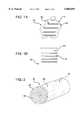
- FIG. 1Ashows an example of an irregularly shaped self-stick product in accordance with the present invention
- FIG. 1Bshows an example of a self-stick product having flange zones where no adhesive is applied in accordance with the present invention
- FIG. 2illustrates a self-stick panel product on a common carrier in packaged form in accordance with the present invention
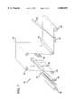
- FIG. 3illustrates a process line for producing self-stick panel products on a common carrier using a compressing adhesive applicator head in accordance with the present invention
- FIG. 4Aillustrates a specific embodiment of an adhesive applicator head usable in connection with the process line shown in FIG. 3 in accordance with the present invention
- FIG. 4Billustrates a conventional, commercially available adhesive applicator head
- FIG. 5illustrates one embodiment of a dispenser machine for dispensing the self-stick panel products from the common carrier in accordance with the present invention
- FIG. 6illustrates yet another embodiment of a dispensing machine for separating self-stick panel products from a common carrier in accordance with the present invention
- FIG. 7illustrates the carrier refurbishing process for refurbishing the common carrier separated from the self-stick panel products in accordance with the present invention.
- FIG. 8illustrates a second embodiment of a process line for providing self-stick panel products on a common carrier using hot air nozzles and a glue header in accordance with the present invention.
- porous matmeans a material which is resiliently compressible to a degree such that after compression the material returns to a substantially identical size and shape and has a surface porosity large enough to permit adhesive to enter the material in a compressed state.
- porous materialinclude polyester fiber, polypropylene fiber, fiberglass or any other mineral fiber to which a binder is added which holds the individual fibers together where they cross one another to form a cohesive wool.
- mineral fiber matsinclude flexible glass wool mats having a density from about 15 kg/m 3 to 80 kg/m 3 and rock wool mats ranging in density from about 60 kg/m 3 to 200 kg/m 3 , for example.
- foam, cellular, or organic fibrous (either woven or unwoven) materialscan form the porous mat.
- the porous matcan include surfaces, other than the one to which the adhesive is to be applied, to which non-porous layers (e.g., aluminum or other material foils, kraft paper, etc.) are applied.
- non-porous layerse.g., aluminum or other material foils, kraft paper, etc.
- the process disclosed hereincan also be used to provide adhesive on a non-porous material such as a non-rigid closed cell foam material which is compressible.
- the self-stick products 10 resulting from the inventive processmay have a uniform or non-uniform thickness, width, or length for application in home appliances such as washing machines, dryers, dish washers, refrigerators, toaster ovens, microwaves, and standard ovens and/or range tops, for example.
- the self-stick products 10can also be used in HVAC systems, automobiles, airplanes, and virtually any other application where sound damping, heat insulation, protection from environmental factors, etc. through use of a compressible material is desirable.
- the self-stick products 10can come in a variety of shapes and sizes desired by the customer, such as a manufacture of HVAC and other OEM equipment, including mixing a variety of shapes and sizes on a single package of self-stick products as desired by the customer.
- the adhesive 12can be an elastomer-based adhesives or hot melt adhesive, or isostatic thermoplastic adhesives.
- nearly any viscous adhesive having a large solids contentcan be used.
- pressure sensitive hot melt adhesives, solvented or waterborne adhesivescan be used, though the solvented adhesives are not as environmentally friendly and the waterborne adhesives can be sensitive to humidity.
- the adhesivescan include flame retardants, antioxidants, or other additives. Adhesives such as those discussed in U.S. Pat. No. 5,106,447 can be used, for instance.
- the inventive self-stick product 10can take on an irregular shape such as illustrated in FIG. 1A, or a polygonal shape such as illustrated in Figure 1B.
- the adhesive strips 11can be selectively formed within an adhesive border zone 13, which is interior to a product border 12 such that the edge of the self-stick panel product 10 does not include exposed adhesive edges.
- non-adhesive zones 14which form flanges where an adhesive is not desired, can be formed by the selective application of the adhesive strips 11 at other locations. These non-adhesive zones 14 are in addition to the adhesive-free zone at the edge of the self-stick product 10.
- the common carrier 15can be a form of release liner substrate material such as silicon paper, kraft paper, polyethylene-coated paper or film, or the like, which is either virgin or recycled.
- the multiple finished products 10may be sequentially arranged in a row along the long dimension of the common carrier 15, or sequentially arranged and arranged side by side in a matrix format, including mixing the shapes of the self-stick products 10 in an order to accommodate the manufacturing steps used by the customer in fabricating an appliance or the like.
- the packaged product 21may be encased in a polyethylene bag or stretch-wrap package 22 to protect the self-stick products 10 during shipping.
- the package 21 of self-stick productscan be produced by a unique process line 30 illustrated in FIG. 3.
- the process line 30includes at least one adhesive applicator head 33 which selectively applies adhesive to the preshaped porous mats 10.
- adhesive applicator heads 33located side-by-side in spaced relationship for approximately the width of the common carrier 15, as illustrated in FIG. 3.
- Each of the adhesive applicator heads 33is separately activated and can be separately displaced toward and away from the entry conveyor 34 to accommodate the different thicknesses of the porous mats 10, as further explained below.
- the process line 30applies adhesive 12 to porous mats 10 in the form of ribbons of adhesive 12 which are forced under controlled pressure and temperature into the mat material.
- the adhesive 12penetrates the pores of the porous material and becomes an integral part of the self-stick product 10.
- the use of pressure by mat compression, rather than creating a vacuum,allows the mat 10 to include an integral non-porous facing material as well as permits the production of preshaped fibrous, e.g., insulation, products while providing adhesive bond characteristics similar to that of the vacuum system.
- porous mats 10, precut or shaped to their finished dimensions,are placed on a product entry conveyor 34.
- the product entry conveyor 34includes product vacuum hold-down hoods 35 and 36 for holding the mats 10 at a fixed location on the conveyor. Alternatively or additionally, pinch or nip rollers can be employed to move the mats 10 along the entry conveyor 34. Vacuum hold-down hoods permit the mats 10 to be fixed to the entry conveyor 34 closer to adhesive applicator heads 33.
- the product entry conveyor 34conveys the preshaped porous mats 10 past adhesive applicator heads 33. There may be only a few or many adhesive applicator heads 33 across the width of the entry conveyor 34, as needs suggest.
- the adhesive applicator heads 33compress portions of the preshaped porous mats 10 and selectively apply a ribbon of adhesive 12 onto the preshaped porous mats 10 while they are compressed. Thereafter, the portions of the porous mats 10 that have been compressed and where the adhesive 12 has been applied substantially return to their original size and shape, thus effectively drawing adhesive that contacts interior surfaces of the mat 10 in its compressed state into the interior of the mats 10 when it returns to its original thickness.
- a secondary hold-down vacuum 36maintains the product position on the exit conveyor 40 until the product is free of compression and travels to the common carrier/porous material contact roller 38.
- the entry conveyor 34transports the adhesive bearing porous mats 10 to a common carrier applicator which includes a roll of common carrier or release liner material 37 which unrolls the common carrier 15 to a common carrier/mat contact roller 38 such that a plurality of preshaped porous mats 10 are adhered to a single common carrier 15 to provide a package 21 of preshaped self-stick panel products on a common carrier.
- a common carrier applicatorwhich includes a roll of common carrier or release liner material 37 which unrolls the common carrier 15 to a common carrier/mat contact roller 38 such that a plurality of preshaped porous mats 10 are adhered to a single common carrier 15 to provide a package 21 of preshaped self-stick panel products on a common carrier.
- multiple pressure rolls 39can be used to assure sufficient adhesive bond between the common carrier 15 and the plurality of preshaped porous mats 10, as well as to act as nip rollers driving the mat/common carrier combination along a exit conveyor 30.
- the distance of these pressure rollers 39 from the conveyoris adjusted to accommodate the thickness of the mats 10, as further explained below.
- the common carrier 15 bearing plural preshaped self-stick panel products 10is then cut to length by a cut-off machine 41, and conveyed by a cut-off machine exit conveyor 42 with another nip roller 43 such that the common carrier 15 bearing the plural preshaped self-stick panel products 10 is rolled up on a roll-up machine 49 as a package 21.
- the adhesive applicator heads 33receive liquefied adhesive from an adhesive bulk storage 31 and an adhesive delivery system 32 for delivering adhesive from the bulk storage to the adhesive applicator heads 33.
- the adhesive bulk storage 31can include an adhesive bulk melter, and the delivery system 32 and adhesive applicator heads 33 can include heaters to maintain the adhesive in a liquid state during its transport when the adhesive is a hot melt adhesive.
- the adhesive delivery system 32includes an adhesive delivery path 32A and a separate adhesive return path 32B such that the adhesive is continuously circulated, whether the applicator heads 33 are dispensing adhesive or not. This leads to several advantages. First, the adhesive delivery system 32 likely would have hot spots that would char the adhesive, or cold spots that would cause the adhesive to form a plug, if it were not continuously circulated. Further, by maintaining the delivery and return paths 32A and 32B at substantially the same pressure, the activation or deactivation of one or more applicator heads 33 will not cause a pressure drop or pressure surge in other applicator heads 33.
- the unique adhesive applicator heads 33 of the present inventioneach include an adhesive supply line 32A, a return line 32B for receiving adhesive, and a supply of pneumatic pressure 47 to control a pressure relief valve 46.
- the adhesive applicator heads 33compress portions of the preshaped porous mats 10 as they pass and include a manifold 33 1 with a leading edge 33 2 having a surface forming an acute angle with the porous mats 10 as the porous mats pass thereunder.
- a trailing edge 33 3 of each of the applicator heads 33has a concave surface facing the porous mats, as illustrated in FIG. 4A.
- An adhesive dispensing port 48is located between the leading edge 33 2 and the trailing edge 33 3 for dispensing adhesive into the passing compressed porous mats.
- FIG. 4Bshows a conventional adhesive applicator head 33', the trailing edge 33 4 of which, if used in the unique process line 30 of the present invention, would interfere with the application and become covered with adhesive, as shown.
- the adhesive applicator heads 33are replaced by a combination of an adhesive dispenser head 82 and hot air manifold 83 with nozzles 84 as illustrated in FIG. 8.
- the adhesive dispenser head 82dispenses ribbons of adhesive 12 onto the preshaped porous mats 10. Thereafter, the hot air nozzles 83 then blow the adhesive into the porous mats 10.
- the application of the adhesive 12is selectively controlled, whether in the adhesive applicator heads 33 of FIG. 3 or in adhesive dispenser head 82 of FIG. 8, by the use of product position sensors 44 and product thickness sensors 45, illustrated in FIG. 3 (although the embodiment illustrated in FIG. 8 would largely be the same), and a microprocessor control or program logic controller represented by an electric valve control line 33 5 .
- the compression of the fiberglass materialis kept constant by the product thickness sensor 45 which adjusts the adhesive applicator head 33 to a correct position.
- the porous mats 10are compressed by a predetermined amount, usually more than 1/16th of an inch, but less than 1/2th of an inch, and preferably 1/8th of an inch.
- the product thickness sensor 45assures constant uniform compression of the porous mat 10 during adhesive application.
- Each adhesive applicator head 33 or adhesive port in the adhesive dispenser head 82is associated with a product position sensor 44.
- the product position sensors 44detects the edges of and holes and bevels in the mats 10 in any suitable manner, such as a photosensor which detects a change in light intensity or color due to the presence or absence of a mat 10, or even a finger sensor to physically touch the mat 10.
- the mat detection signalthen activates a counter (not shown) connected to an encoder (not shown) attached to the entry conveyor 34 to count a number of pulses for the duration that adhesive is to be applied within a predetermined zone of the mat 10.
- Each of the product thickness sensors 45can be associated with an adhesive applicator head 33 to control the vertical displacement of the applicator head 33 relative to the top surface of the mat 10 to assure proper compression.
- the product thickness sensor 45may be omitted in the embodiment illustrated in FIG. 8, but alternatively may be used to control the force at which the hot air exits the nozzles 83.
- the unique process line 30 of the present inventioncan be used to provide plural self-stick products 10 of unique shapes on a single common carrier 15.
- the system for providing the preshaped self-stick panel productsincludes a dispenser machine 50, 60.
- the dispenser machine 50includes cradle rollers 52 for supporting a roll of products 41.
- the common carrier 15is drawn from the roll of products 41 the self-stick panel products unwind from the roll 41 through pinch rollers 53.
- a separating bar 54is used to pull the common carrier 15 away from the self-stick panel products 10 for either automatic or manual placement on the substrate to which the self-stick panel product is to be adhered, such as the metal panels of an HVAC system.
- a pinch roller mechanism 55is used to draw the common carrier 15 into a release liner container 56.
- a self-stick product 10 on the common carrier 15is indexed by a machine operator so that it is contained within the pinch rollers 53. These rollers 53 provide a back-tension on the common carrier 15 so that the common carrier 15 can be held tightly against the separating bar 54.
- the common carrieris threaded by hand into the pinch rollers 55, which are driven such that the release liner 15 is pulled across a separating bar 54 and is deposited to the common carrier container 56 of the machine or is rewound on a mandrel or reel 64 (see FIG. 6) for possible recycling.
- FIG. 6illustrates yet another dispensing mechanism 60 wherein the package 41 of self-stick panel products on a common carrier is placed into cradle rollers 52, as done in the embodiment illustrated in FIG. 5.
- a small diameter stripper roller 61is used to separate the common carrier 15 from the self-stick panel products 10.
- the common carrier 15then passes over another roller 62 and onto a reel 64.
- the reel 64once a sufficient amount of common carrier 15 placed is placed thereon, is then sent back to the manufacturer for recycling.
- An outfeed conveyor 63then conveys the self-stick panel products 10 to a position where they can be utilized for their end purpose.
- the common carrier 15 which has been released from the packaged product 41can be returned to a fabrication center and placed into a common carrier refurbisher 70.
- the reel 64 or the common carrier container 56is placed at one end of the refurbisher 70.
- a splice table 72is used to juxtapose two terminal ends of common carrier 15 to be recycled.
- a splice tape 71is then used to splice together the two terminal ends of the common carrier 15.
- the spliced together common carrier 15then passes several rollers 73 such that the common carrier 15 passes through a wash mechanism including a wash brush roller 74 and a dryer head 75.
- a wash mechanismincluding a wash brush roller 74 and a dryer head 75.
- the dryer head 75can be placed on both sides of the common carrier 15.
- the refurbished common carrier 15is then output along an output conveyor which includes a vacuum hood (not illustrated) or pinch rollers 76 which effectively draws the common carrier through the refurbisher 70. Thereafter, a cutoff machine or chopper 77 cuts the spliced common carrier into predetermined lengths which are placed on a rewinder master 78. This rewinder master 78 may then be used as the roll 37 of common carrier illustrated in FIGS. 3 and 8.
- a production process for producing a self-stick panel product on a common carrierapplies pressure sensitive hot melt adhesive or the like in extruded ribbon form to fiberglass insulation or other porous mat 10.
- the processprovides excellent adhesion to the surface of the porous mat 10 while allowing this process to be used for products which have an integral facing material bonded to the opposite side of the porous mat 10.
- This unique processis accomplished without the use of vacuums, or elevated and ramped conveyors.
- the unique processallows finished cut porous material parts of various uniform and non-uniform shapes (including products with holes, voids, and non-adhesive applied flange zones) to be coated with adhesive at production speeds and facilitates the packaging of these individual products 10 in a common roll 41 for utilizing a common release material 15.
- These self-stick products 10can then be unpackaged by the customer such that the individual self-stick products 10 can be manually, semi-automatically or automatically dispensed from the dispenser machine 60 or 70.
- the individual products 10are separated from the protective release liner substrate 15 such that the release substrate 15 is collected within the device, thereby facilitating possible recycling of the common carrier 15.
- the self-stick products 10 of finished shapeare then presented to the person or machine in such a manner that the products are easily grasped, held and removed from the device without the difficulty of attempting to manually separate the release liner substrate from the adhesive material.
Landscapes
- Physics & Mathematics (AREA)
- Engineering & Computer Science (AREA)
- Architecture (AREA)
- Acoustics & Sound (AREA)
- Electromagnetism (AREA)
- Civil Engineering (AREA)
- Structural Engineering (AREA)
- Application Of Or Painting With Fluid Materials (AREA)
- Processing And Handling Of Plastics And Other Materials For Molding In General (AREA)
Abstract
Description
Claims (21)
Priority Applications (4)
| Application Number | Priority Date | Filing Date | Title |
|---|---|---|---|
| US08/741,848US5868891A (en) | 1996-10-31 | 1996-10-31 | Peel and stick insulation having a common carrier sheet |
| US08/869,347US6062287A (en) | 1996-10-31 | 1997-06-05 | Apparatus for dispensing peel and stick product from a common carrier sheet |
| CA002551966ACA2551966A1 (en) | 1996-10-31 | 1997-10-16 | Peel and stick insulation having a common carrier sheet |
| CA002218462ACA2218462C (en) | 1996-10-31 | 1997-10-16 | Peel and stick insulation having a common carrier sheet |
Applications Claiming Priority (1)
| Application Number | Priority Date | Filing Date | Title |
|---|---|---|---|
| US08/741,848US5868891A (en) | 1996-10-31 | 1996-10-31 | Peel and stick insulation having a common carrier sheet |
Related Child Applications (1)
| Application Number | Title | Priority Date | Filing Date |
|---|---|---|---|
| US08/869,347Continuation-In-PartUS6062287A (en) | 1996-10-31 | 1997-06-05 | Apparatus for dispensing peel and stick product from a common carrier sheet |
Publications (1)
| Publication Number | Publication Date |
|---|---|
| US5868891Atrue US5868891A (en) | 1999-02-09 |
Family
ID=24982456
Family Applications (1)
| Application Number | Title | Priority Date | Filing Date |
|---|---|---|---|
| US08/741,848Expired - Fee RelatedUS5868891A (en) | 1996-10-31 | 1996-10-31 | Peel and stick insulation having a common carrier sheet |
Country Status (2)
| Country | Link |
|---|---|
| US (1) | US5868891A (en) |
| CA (1) | CA2218462C (en) |
Cited By (29)
| Publication number | Priority date | Publication date | Assignee | Title |
|---|---|---|---|---|
| NL1011603C2 (en)* | 1999-03-19 | 2000-09-27 | Rockwool Lapinus Bv | Self-adhesive insulation blanket. |
| WO2001016534A1 (en)* | 1999-08-31 | 2001-03-08 | Owens Corning | Perforated faced insulation assembly and method of making the same |
| US6207245B1 (en)* | 1998-10-23 | 2001-03-27 | Scott Industries, Inc. | Fiberglass insulation blanket with release liner assembly and method |
| US20030195807A1 (en)* | 2000-10-12 | 2003-10-16 | Frank S. Maggio | Method and system for verifying exposure to message content via a printed response |
| US20040015399A1 (en)* | 2000-10-12 | 2004-01-22 | Maggio Frank S. | Method and system for verifying exposure to message content delivered via outdoor media or in a concentrated format |
| US20040031212A1 (en)* | 2000-11-08 | 2004-02-19 | Marjan Sircelj | Insulation of slanting roof structures |
| US20040107138A1 (en)* | 2000-10-12 | 2004-06-03 | Maggio Frank S. | Method and system for verifying immersion in advertising content via an immersion enhancing content vignette |
| US6779577B1 (en)* | 1999-06-30 | 2004-08-24 | Nichiha Corporation | Building boards, manufacturing apparatus and prefoamed plastics |
| US20040220858A1 (en)* | 2003-05-02 | 2004-11-04 | Maggio Frank S. | Method and system for verifying exposure to message content delivered via subscription networks |
| US20040255556A1 (en)* | 2003-06-17 | 2004-12-23 | Cryovac, Inc. | Method and apparatus for making a pre-padded food bag |
| US20050060232A1 (en)* | 2000-10-12 | 2005-03-17 | Maggio Frank S. | Method and system for interacting with a writing |
| US20050158521A1 (en)* | 2004-01-20 | 2005-07-21 | Quietflex Manufacturing Company, L.P. | Insulation and methods for making and securing insulation |
| US20060129458A1 (en)* | 2000-10-12 | 2006-06-15 | Maggio Frank S | Method and system for interacting with on-demand video content |
| US20060253330A1 (en)* | 2000-10-12 | 2006-11-09 | Maggio Frank S | Method and system for automatically substituting media content |
| US20060271437A1 (en)* | 2005-05-26 | 2006-11-30 | Maggio Frank S | System and method for home product delivery |
| US20060282319A1 (en)* | 2000-10-12 | 2006-12-14 | Maggio Frank S | Method and system for substituting media content |
| US20070290878A1 (en)* | 2006-04-07 | 2007-12-20 | Media Ip Holdings, Llc | System and method for interacting with automobile race and advertising content |
| US20080032277A1 (en)* | 2006-04-08 | 2008-02-07 | Media Ip Holdings, Llc | Dynamic multiple choice answers |
| US20080302460A1 (en)* | 2007-06-07 | 2008-12-11 | Cupid Foundations, Inc. | Method and system for manufacturing garments with support panels |
| US20090165942A1 (en)* | 2007-12-26 | 2009-07-02 | National Starch And Chemical Investment Holding Corporation | Insulation and Method of Installing |
| US20090260756A1 (en)* | 2008-04-18 | 2009-10-22 | Alf Martin Book | Method And Apparatus For Applying Heat Activated Transfer Adhesives |
| US20100272943A1 (en)* | 2009-04-22 | 2010-10-28 | Robert Kintu Ddamulira | Carrier-free adhesive film |
| US20110218086A1 (en)* | 2010-03-05 | 2011-09-08 | Boren John P | Apparatus and method of gravity-assisted spinal stretching |
| US20140238611A1 (en)* | 2011-11-01 | 2014-08-28 | Hyundai Dymos Incorporated | Apparatus for adhering a soft slab and a covering material together |
| CN106437072A (en)* | 2016-10-11 | 2017-02-22 | 广西福美新材料有限公司 | Flexible facing sheet with self-adhesive layer and production method of flexible facing sheet |
| CN113275293A (en)* | 2021-04-02 | 2021-08-20 | 董光伟 | New energy battery is based on cleaning device of oxalic acid solution performance |
| US11512481B1 (en)* | 2019-02-22 | 2022-11-29 | Base King, Llc | Portable apparatus for application of sheet adhesive to flooring |
| US12039895B2 (en) | 2021-07-28 | 2024-07-16 | S+P Samson Gmbh | Label, label tape and method for manufacturing labels |
| US20240392558A1 (en)* | 2023-05-24 | 2024-11-28 | Johns Manville | Self-stick batt |
Citations (18)
| Publication number | Priority date | Publication date | Assignee | Title |
|---|---|---|---|---|
| US3226910A (en)* | 1964-11-13 | 1966-01-04 | Edmond A Steffey | Method for packaging appliques |
| US3598679A (en)* | 1968-03-04 | 1971-08-10 | Vitta Corp | Method of making a pressure-transferrable tape |
| US3869328A (en)* | 1972-03-16 | 1975-03-04 | Instance Ltd David J | Reeling self-adhesive labels |
| US3888716A (en)* | 1972-06-05 | 1975-06-10 | Kemlite Corp | Preparation of resin impregnated glass fiber sheets |
| US4022248A (en)* | 1975-09-24 | 1977-05-10 | Owens-Corning Fiberglas Corporation | Pipe having insulating material and cover and having two strips of self-sealing adhesive material |
| US4134948A (en)* | 1970-03-30 | 1979-01-16 | Scott Paper Company | Method of making a nonwoven fabric |
| US4447490A (en)* | 1981-11-28 | 1984-05-08 | Rheinhold & Mahla Dammstoffe Gmbh | Laminated mineral fibre mat and processes for its production |
| US4700521A (en)* | 1986-04-28 | 1987-10-20 | Cover Craig H | Multilayered insulation batt for building structures |
| US4764234A (en)* | 1986-12-18 | 1988-08-16 | The Kendall Company | Method of applying adhesive |
| US4797170A (en)* | 1986-07-07 | 1989-01-10 | Jactac, Inc. | System for holding carpet in place without stretching |
| US4923539A (en)* | 1988-09-16 | 1990-05-08 | Stanztechnik Gmbh R+S | Method and apparatus for manufacturing trim panels including several trim components |
| US4931125A (en)* | 1985-06-18 | 1990-06-05 | The Dow Chemical Company | Method for adhesive bonding with pretreatment of components |
| US5019197A (en)* | 1988-11-07 | 1991-05-28 | Henderson Lionel A | Method of making composites having layers of the same or different firmness |
| US5106447A (en)* | 1990-07-17 | 1992-04-21 | National Starch And Chemical Investment Holding Corporation | Bonding method employing hot melt adhesives for insulation assembly |
| US5112678A (en)* | 1990-08-17 | 1992-05-12 | Atlas Roofing Corporation | Method and composition for coating mat and articles produced therewith |
| US5277955A (en)* | 1989-12-08 | 1994-01-11 | Owens-Corning Fiberglas Technology Inc. | Insulation assembly |
| US5472541A (en)* | 1993-04-26 | 1995-12-05 | Astechnologies, Inc. | Method of applying adhesive to porous materials |
| EP0725117A2 (en)* | 1995-01-12 | 1996-08-07 | Owens Corning | Insulation assembly and method for applying adhesive thereto |
- 1996
- 1996-10-31USUS08/741,848patent/US5868891A/ennot_activeExpired - Fee Related
- 1997
- 1997-10-16CACA002218462Apatent/CA2218462C/ennot_activeExpired - Fee Related
Patent Citations (19)
| Publication number | Priority date | Publication date | Assignee | Title |
|---|---|---|---|---|
| US3226910A (en)* | 1964-11-13 | 1966-01-04 | Edmond A Steffey | Method for packaging appliques |
| US3598679A (en)* | 1968-03-04 | 1971-08-10 | Vitta Corp | Method of making a pressure-transferrable tape |
| US4134948A (en)* | 1970-03-30 | 1979-01-16 | Scott Paper Company | Method of making a nonwoven fabric |
| US3869328A (en)* | 1972-03-16 | 1975-03-04 | Instance Ltd David J | Reeling self-adhesive labels |
| US3888716A (en)* | 1972-06-05 | 1975-06-10 | Kemlite Corp | Preparation of resin impregnated glass fiber sheets |
| US4022248A (en)* | 1975-09-24 | 1977-05-10 | Owens-Corning Fiberglas Corporation | Pipe having insulating material and cover and having two strips of self-sealing adhesive material |
| US4447490A (en)* | 1981-11-28 | 1984-05-08 | Rheinhold & Mahla Dammstoffe Gmbh | Laminated mineral fibre mat and processes for its production |
| US4931125A (en)* | 1985-06-18 | 1990-06-05 | The Dow Chemical Company | Method for adhesive bonding with pretreatment of components |
| US4700521A (en)* | 1986-04-28 | 1987-10-20 | Cover Craig H | Multilayered insulation batt for building structures |
| US4797170B1 (en)* | 1986-07-07 | 1991-05-21 | Jac Tac Inc | |
| US4797170A (en)* | 1986-07-07 | 1989-01-10 | Jactac, Inc. | System for holding carpet in place without stretching |
| US4764234A (en)* | 1986-12-18 | 1988-08-16 | The Kendall Company | Method of applying adhesive |
| US4923539A (en)* | 1988-09-16 | 1990-05-08 | Stanztechnik Gmbh R+S | Method and apparatus for manufacturing trim panels including several trim components |
| US5019197A (en)* | 1988-11-07 | 1991-05-28 | Henderson Lionel A | Method of making composites having layers of the same or different firmness |
| US5277955A (en)* | 1989-12-08 | 1994-01-11 | Owens-Corning Fiberglas Technology Inc. | Insulation assembly |
| US5106447A (en)* | 1990-07-17 | 1992-04-21 | National Starch And Chemical Investment Holding Corporation | Bonding method employing hot melt adhesives for insulation assembly |
| US5112678A (en)* | 1990-08-17 | 1992-05-12 | Atlas Roofing Corporation | Method and composition for coating mat and articles produced therewith |
| US5472541A (en)* | 1993-04-26 | 1995-12-05 | Astechnologies, Inc. | Method of applying adhesive to porous materials |
| EP0725117A2 (en)* | 1995-01-12 | 1996-08-07 | Owens Corning | Insulation assembly and method for applying adhesive thereto |
Cited By (37)
| Publication number | Priority date | Publication date | Assignee | Title |
|---|---|---|---|---|
| US6207245B1 (en)* | 1998-10-23 | 2001-03-27 | Scott Industries, Inc. | Fiberglass insulation blanket with release liner assembly and method |
| NL1011603C2 (en)* | 1999-03-19 | 2000-09-27 | Rockwool Lapinus Bv | Self-adhesive insulation blanket. |
| WO2000057101A1 (en)* | 1999-03-19 | 2000-09-28 | Rockwool Lapinus B.V. | Self-adhesive insulation blanket |
| US6779577B1 (en)* | 1999-06-30 | 2004-08-24 | Nichiha Corporation | Building boards, manufacturing apparatus and prefoamed plastics |
| WO2001016534A1 (en)* | 1999-08-31 | 2001-03-08 | Owens Corning | Perforated faced insulation assembly and method of making the same |
| US6444289B1 (en) | 1999-08-31 | 2002-09-03 | Owens Corning Fiberglas Technology, Inc. | Perforated faced insulation assembly |
| US20040107138A1 (en)* | 2000-10-12 | 2004-06-03 | Maggio Frank S. | Method and system for verifying immersion in advertising content via an immersion enhancing content vignette |
| US20040015399A1 (en)* | 2000-10-12 | 2004-01-22 | Maggio Frank S. | Method and system for verifying exposure to message content delivered via outdoor media or in a concentrated format |
| US20030195807A1 (en)* | 2000-10-12 | 2003-10-16 | Frank S. Maggio | Method and system for verifying exposure to message content via a printed response |
| US20050060232A1 (en)* | 2000-10-12 | 2005-03-17 | Maggio Frank S. | Method and system for interacting with a writing |
| US20060129458A1 (en)* | 2000-10-12 | 2006-06-15 | Maggio Frank S | Method and system for interacting with on-demand video content |
| US20060253330A1 (en)* | 2000-10-12 | 2006-11-09 | Maggio Frank S | Method and system for automatically substituting media content |
| US20060282319A1 (en)* | 2000-10-12 | 2006-12-14 | Maggio Frank S | Method and system for substituting media content |
| US20040031212A1 (en)* | 2000-11-08 | 2004-02-19 | Marjan Sircelj | Insulation of slanting roof structures |
| US20040220858A1 (en)* | 2003-05-02 | 2004-11-04 | Maggio Frank S. | Method and system for verifying exposure to message content delivered via subscription networks |
| US20040255556A1 (en)* | 2003-06-17 | 2004-12-23 | Cryovac, Inc. | Method and apparatus for making a pre-padded food bag |
| US20050158521A1 (en)* | 2004-01-20 | 2005-07-21 | Quietflex Manufacturing Company, L.P. | Insulation and methods for making and securing insulation |
| US20060271437A1 (en)* | 2005-05-26 | 2006-11-30 | Maggio Frank S | System and method for home product delivery |
| US20070290878A1 (en)* | 2006-04-07 | 2007-12-20 | Media Ip Holdings, Llc | System and method for interacting with automobile race and advertising content |
| US20080032277A1 (en)* | 2006-04-08 | 2008-02-07 | Media Ip Holdings, Llc | Dynamic multiple choice answers |
| US20080302460A1 (en)* | 2007-06-07 | 2008-12-11 | Cupid Foundations, Inc. | Method and system for manufacturing garments with support panels |
| US20090165942A1 (en)* | 2007-12-26 | 2009-07-02 | National Starch And Chemical Investment Holding Corporation | Insulation and Method of Installing |
| US7934531B2 (en)* | 2008-04-18 | 2011-05-03 | Brady Worldwide, Inc. | Method and apparatus for applying heat activated transfer adhesives |
| US20090260756A1 (en)* | 2008-04-18 | 2009-10-22 | Alf Martin Book | Method And Apparatus For Applying Heat Activated Transfer Adhesives |
| US9394701B2 (en) | 2009-04-22 | 2016-07-19 | W.F. Taylor Llc | Carrier-free adhesive film |
| US20100272943A1 (en)* | 2009-04-22 | 2010-10-28 | Robert Kintu Ddamulira | Carrier-free adhesive film |
| US20110218086A1 (en)* | 2010-03-05 | 2011-09-08 | Boren John P | Apparatus and method of gravity-assisted spinal stretching |
| US20140238611A1 (en)* | 2011-11-01 | 2014-08-28 | Hyundai Dymos Incorporated | Apparatus for adhering a soft slab and a covering material together |
| US9486958B2 (en)* | 2011-11-01 | 2016-11-08 | Hyundai Dymos Incorporated | Apparatus for adhering a soft slab and a covering material together |
| EP2774758B1 (en)* | 2011-11-01 | 2018-10-03 | Hyundai Dymos Incorporated | Apparatus for adhering a soft slab and a covering material together |
| CN106437072A (en)* | 2016-10-11 | 2017-02-22 | 广西福美新材料有限公司 | Flexible facing sheet with self-adhesive layer and production method of flexible facing sheet |
| US11512481B1 (en)* | 2019-02-22 | 2022-11-29 | Base King, Llc | Portable apparatus for application of sheet adhesive to flooring |
| CN113275293A (en)* | 2021-04-02 | 2021-08-20 | 董光伟 | New energy battery is based on cleaning device of oxalic acid solution performance |
| CN113275293B (en)* | 2021-04-02 | 2022-09-23 | 湖南冉旭能源科技有限公司 | New energy battery is based on cleaning device of oxalic acid solution performance |
| US12039895B2 (en) | 2021-07-28 | 2024-07-16 | S+P Samson Gmbh | Label, label tape and method for manufacturing labels |
| US20240392558A1 (en)* | 2023-05-24 | 2024-11-28 | Johns Manville | Self-stick batt |
| US12371897B2 (en)* | 2023-05-24 | 2025-07-29 | Johns Manville | Self-stick batt |
Also Published As
| Publication number | Publication date |
|---|---|
| CA2218462A1 (en) | 1998-04-30 |
| CA2218462C (en) | 2007-07-31 |
Similar Documents
| Publication | Publication Date | Title |
|---|---|---|
| US5868891A (en) | Peel and stick insulation having a common carrier sheet | |
| US5942321A (en) | Headliner | |
| EP0847465B1 (en) | Encapsulated insulation assembly | |
| CA2120111C (en) | Method of applying adhesive to porous materials | |
| KR100399349B1 (en) | How to cover fiberglass insulation | |
| US20110189410A1 (en) | Recyclable surface covering and method and system for manufacturing a recyclable surface covering | |
| EP0725117B1 (en) | Insulation assembly and method for applying adhesive thereto | |
| AU2003296797A1 (en) | Method and device for making a composite plate | |
| HU209004B (en) | Method for continuous covering at least two neighbouring plates of building panels | |
| US6062287A (en) | Apparatus for dispensing peel and stick product from a common carrier sheet | |
| EP0185664B1 (en) | Mirror laminates | |
| EP0832787A1 (en) | Headliner and method of manufacturing | |
| CA2551966A1 (en) | Peel and stick insulation having a common carrier sheet | |
| CA2228093A1 (en) | Apparatus for dispensing peel and stick product from a common carrier sheet | |
| KR100459338B1 (en) | Acoustic absorption panel | |
| JP2004502052A (en) | Method for manufacturing floors using recycled materials | |
| EP0886575B1 (en) | Plate, panel or similar, of thermoformable multilayer material and method for its fabrication | |
| AU620440B2 (en) | Method for the manufacture of laminated elements | |
| JP3229552B2 (en) | Manufacturing method of sound absorbing panel | |
| JP5105793B2 (en) | Insulating sound absorbing material and method for producing the same | |
| WO2001023176A1 (en) | Method of forming a sheet of reinforced product | |
| JPH01314137A (en) | Manufacturing method for cushioning packaging material | |
| JPH05124000A (en) | Interior laminated sheet member fusing method and device therefor | |
| JPS5858237B2 (en) | Adhesive-based automatic pasting device | |
| JPS6134986B2 (en) |
Legal Events
| Date | Code | Title | Description |
|---|---|---|---|
| AS | Assignment | Owner name:OWENS-CORNING FIBERGLAS TECHNOLOGY, INC., ILLINOIS Free format text:ASSIGNMENT OF ASSIGNORS INTEREST;ASSIGNORS:MCCALL III, JOHN M.;WEIR, CHARLES RUSSELL;ERENST, FREDERICK R.;AND OTHERS;REEL/FRAME:008375/0615;SIGNING DATES FROM 19970129 TO 19970205 | |
| FEPP | Fee payment procedure | Free format text:PAYOR NUMBER ASSIGNED (ORIGINAL EVENT CODE: ASPN); ENTITY STATUS OF PATENT OWNER: LARGE ENTITY | |
| FPAY | Fee payment | Year of fee payment:4 | |
| REMI | Maintenance fee reminder mailed | ||
| FPAY | Fee payment | Year of fee payment:8 | |
| AS | Assignment | Owner name:OWENS CORNING INTELLECTUAL CAPITAL, LLC, OHIO Free format text:ASSIGNMENT OF ASSIGNORS INTEREST;ASSIGNOR:OWENS-CORNING FIBERGLASS TECHNOLOGY, INC.;REEL/FRAME:019795/0433 Effective date:20070803 Owner name:OWENS CORNING INTELLECTUAL CAPITAL, LLC,OHIO Free format text:ASSIGNMENT OF ASSIGNORS INTEREST;ASSIGNOR:OWENS-CORNING FIBERGLASS TECHNOLOGY, INC.;REEL/FRAME:019795/0433 Effective date:20070803 Owner name:OWENS CORNING INTELLECTUAL CAPITAL, LLC, OHIO Free format text:ASSIGNMENT OF ASSIGNORS INTEREST;ASSIGNOR:OWENS-CORNING FIBERGLAS TECHNOLOGY, INC.;REEL/FRAME:019795/0433 Effective date:20070803 | |
| REMI | Maintenance fee reminder mailed | ||
| LAPS | Lapse for failure to pay maintenance fees | ||
| STCH | Information on status: patent discontinuation | Free format text:PATENT EXPIRED DUE TO NONPAYMENT OF MAINTENANCE FEES UNDER 37 CFR 1.362 | |
| FP | Lapsed due to failure to pay maintenance fee | Effective date:20110209 |