US5868794A - AED and battery pack with anticipatory battery disengagement detection - Google Patents
AED and battery pack with anticipatory battery disengagement detectionDownload PDFInfo
- Publication number
- US5868794A US5868794AUS09/057,312US5731298AUS5868794AUS 5868794 AUS5868794 AUS 5868794AUS 5731298 AUS5731298 AUS 5731298AUS 5868794 AUS5868794 AUS 5868794A
- Authority
- US
- United States
- Prior art keywords
- aed
- battery pack
- electrodes
- battery
- disposed
- Prior art date
- Legal status (The legal status is an assumption and is not a legal conclusion. Google has not performed a legal analysis and makes no representation as to the accuracy of the status listed.)
- Expired - Lifetime
Links
Images


Classifications
- A—HUMAN NECESSITIES
- A61—MEDICAL OR VETERINARY SCIENCE; HYGIENE
- A61N—ELECTROTHERAPY; MAGNETOTHERAPY; RADIATION THERAPY; ULTRASOUND THERAPY
- A61N1/00—Electrotherapy; Circuits therefor
- A61N1/18—Applying electric currents by contact electrodes
- A61N1/32—Applying electric currents by contact electrodes alternating or intermittent currents
- A61N1/38—Applying electric currents by contact electrodes alternating or intermittent currents for producing shock effects
- A61N1/39—Heart defibrillators
- A61N1/3925—Monitoring; Protecting
- A61N1/3931—Protecting, e.g. back-up systems
- A—HUMAN NECESSITIES
- A61—MEDICAL OR VETERINARY SCIENCE; HYGIENE
- A61N—ELECTROTHERAPY; MAGNETOTHERAPY; RADIATION THERAPY; ULTRASOUND THERAPY
- A61N1/00—Electrotherapy; Circuits therefor
- A61N1/18—Applying electric currents by contact electrodes
- A61N1/32—Applying electric currents by contact electrodes alternating or intermittent currents
- A61N1/38—Applying electric currents by contact electrodes alternating or intermittent currents for producing shock effects
- A61N1/39—Heart defibrillators
- A61N1/3975—Power supply
- A—HUMAN NECESSITIES
- A61—MEDICAL OR VETERINARY SCIENCE; HYGIENE
- A61N—ELECTROTHERAPY; MAGNETOTHERAPY; RADIATION THERAPY; ULTRASOUND THERAPY
- A61N1/00—Electrotherapy; Circuits therefor
- A61N1/18—Applying electric currents by contact electrodes
- A61N1/32—Applying electric currents by contact electrodes alternating or intermittent currents
- A61N1/36—Applying electric currents by contact electrodes alternating or intermittent currents for stimulation
- A61N1/372—Arrangements in connection with the implantation of stimulators
- A61N1/378—Electrical supply
- H—ELECTRICITY
- H01—ELECTRIC ELEMENTS
- H01M—PROCESSES OR MEANS, e.g. BATTERIES, FOR THE DIRECT CONVERSION OF CHEMICAL ENERGY INTO ELECTRICAL ENERGY
- H01M50/00—Constructional details or processes of manufacture of the non-active parts of electrochemical cells other than fuel cells, e.g. hybrid cells
- H01M50/20—Mountings; Secondary casings or frames; Racks, modules or packs; Suspension devices; Shock absorbers; Transport or carrying devices; Holders
- Y—GENERAL TAGGING OF NEW TECHNOLOGICAL DEVELOPMENTS; GENERAL TAGGING OF CROSS-SECTIONAL TECHNOLOGIES SPANNING OVER SEVERAL SECTIONS OF THE IPC; TECHNICAL SUBJECTS COVERED BY FORMER USPC CROSS-REFERENCE ART COLLECTIONS [XRACs] AND DIGESTS
- Y02—TECHNOLOGIES OR APPLICATIONS FOR MITIGATION OR ADAPTATION AGAINST CLIMATE CHANGE
- Y02E—REDUCTION OF GREENHOUSE GAS [GHG] EMISSIONS, RELATED TO ENERGY GENERATION, TRANSMISSION OR DISTRIBUTION
- Y02E60/00—Enabling technologies; Technologies with a potential or indirect contribution to GHG emissions mitigation
- Y02E60/10—Energy storage using batteries
Definitions
- the present inventionrelates to an automated external defibrillator (AED) and a battery pack that powers the AED. More particularly, the present invention is an AED and a battery pack, the battery pack being removable and containing a plurality of individual battery cells and is designed for use with the AED.
- AEDautomated external defibrillator
- the battery packshould have the following characteristics.
- the battery packshould be removably coupled to the AED. When coupled to the AED, the battery pack should be held semi-rigidly in place such that virtually no relative motion occurs between the battery pack and the AED. Additionally, the battery pack should be held securely in place once joined to the AED so that it is very unlikely that the battery pack will become inadvertently disengaged from the AED.
- An AEDtypically uses integral batteries to power various electronic components of the AED and to generate the very high voltages necessary for shocking a patient.
- the AEDhas the capability of delivering very high voltage impulses to a stricken patient. Such voltages may exceed 2,000 volts.
- the high voltagesare typically developed from the relatively low voltage battery by charging a capacitor bank prior to delivery of the shock to the patient. Removal of the battery pack from the AED removes power from the electronic components that provide control to the capacitor bank. If the battery is removed from the AED when the capacitors are charged to the high voltage, there is no control remaining over the ultimate discharge of the capacitors. Accordingly, in addition to the aforementioned characteristics, there is a need to sense the imminent removal of the battery from the AED and, while there is still power to the various electronic components and control remaining, to safely discharge the capacitors.
- the AED of the present inventionsubstantially meets the aforementioned needs.
- the AEDis configured to sense the imminent removal of the battery from the AED and, while there is still power to the various electronic components and control remaining, safely discharge the capacitors of the AED. Means are provided to anticipate the disconnecting of the battery from the AED so that the discharge is accomplished in a controlled manner.
- the AED of the present inventionhas a housing. Electronic circuitry is disposed in the housing for delivery of an electric shock to a stricken patient.
- a removable battery packis selectively, operably, communicatively coupled to the electronic circuitry.
- the battery packhas an anticipatory detector for generating an anticipatory signal to the electronic circuitry. The signal indicates to the electronic circuitry that the disengagement of the battery pack from the AED is imminent.
- the present inventionfurther includes a method for ensuring that the high voltage storage circuits of the AED are safely discharged prior to disengaging the battery pack from the AED.
- FIG. 1is a perspective view of an automated external defibrillator
- FIG. 2is a perspective view of the AED of FIG. 1 having the lid opened;
- FIG. 3is a perspective view of the AED having a rescue information data card positioned for insertion therein;
- FIG. 4is a plan view of a diagnostic display of the AED
- FIG. 5is a block diagram of an electrical system of the AED
- FIG. 6is a front perspective view of the battery pack of the present invention.
- FIG. 7is a rear perspective view of the battery pack disengaged from the AED
- FIG. 8is a rear perspective view of the battery pack positioned with respect to the AED just prior to engagement therewith;
- FIG. 9is a rear perspective view of the battery pack with the hinge end thereof partially engaged with the AED;
- FIG. 10is a front perspective view of the battery pack and AED positioned as depicted in FIG. 9;
- FIG. 11is a rear quarter perspective view of the battery pack being rotated into engagement with the AED in a position just prior to engagement of the latch end of the battery pack with the AED;
- FIG. 12is a top planar view of the bottom half of the AED with the battery pack engaged therewith;
- FIG. 13is a schematic diagram of the battery removal safety circuit of the present invention.
- FIG. 14is a rear elevational view of the battery pack.
- FIG. 15is a top elevational view of the battery pack.
- an emergency electronic device and, more particularly, an automated external defibrillator (AED) 10 with the ability to store rescue informationmay be appreciated.
- the stored rescue informationmay include patient data, AED operational data and/or sound recorded proximate AED 10.
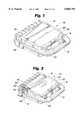
- AED 10includes a plastic case 12 with a carrying handle 14 on the front portion.
- a battery compartment(as will be later described) in the rear portion of AED 10 encloses a battery pack 16, the battery pack 16 being removably disposed within the battery compartment.
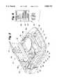
- Case 12also includes an electrode compartment 26 defined in the top portion of case 12 (depicted in FIG. 2).
- An illuminatable rescue/resume switch 18is disposed adjacent to electrode compartment 26.
- the electrode compartment 26is closed by lid 27, lid 27 being mounted to case 12 by hinges (not visible).
- Lid 27covers the rescue/resume switch 18 when the lid 27 is in the closed disposition, the closed disposition being depicted in FIGS. 1 and 3.
- the rescue/resume switch 18is actually a single switch with illuminatable labels alternatively indicating the "resume” 49 or the "rescue” 48 function, "rescue” 48 appearing above the switch 18 and “resume” 49 appearing below the switch 18, depending on whether AED 10 is cuing the operator to perform a rescue or resume operation by activating switch 18.
- a data card storage bracket 28is formed on the inside of the lid 27 for holding a data card 29 for use in recording the parameters of a rescue intervention.
- the data card 29is insertable into the data card slot 24, as indicated by Arrow A in FIG. 3.
- a bayonet-type releasable latch 30holds lid 27 closed when AED 10 is not in use by engaging a receiving recess 31 (FIG. 2) defined in the floor of electrode compartment 26.
- Lid 27is opened by grasping the underside of latch 30, pushing in to disengage latch 30 from recess 31 and lifting upward on latch 30 to gain access to electrode compartment 26. Opening the lid 27 activates a lid open switch 25.
- the lid open switch 25may be any suitable switch such as a reed switch or a Hall effect switch.
- Electrodes 50are disposed within electrode compartment 26 and are removably connected to electrode connector 32 by connector 58. Electrodes 50 typically include a pair of electrodes for attachment to a patient in a sealed package 60.
- FIG. 5is a block diagram of the electrical system 70 of AED 10.
- the overall operation of AED 10is controlled by a digital microprocessor-based control system 72, which includes a processor 74 interfaced to program memory 76, data memory 77, event memory 78 and real time clock 79.
- the digital microprocessor-based control system 72may be initiated by operation of the lid open switch 25 when the lid 27 is opened and may be deactivated by operation of the lid open switch 25 when the lid 27 is closed.
- the operating program executed by processor 74is stored in program memory 76.
- Data memory 77is used by processor 74 as a scratch pad memory during the execution of the operating program.
- Battery 80Electrical power is preferably provided by a lithium sulphur dioxide battery 80 which is enclosed in battery pack 16, battery pack 16 being removably positioned within the battery compartment.
- Battery 80may be comprised of a plurality of battery cells that are electrically coupled together. Battery 80 is connected to power generation circuit 82.
- the "Battery Status" indicator light 38indicates the charge status of battery 80 and prompts the operator to replace battery 80 when needed.
- power generation circuit 82During normal operation, power generation circuit 82 generates a 12V supply and regulated ⁇ 5V and 3.3V supplies with the power provided by battery 80.
- the ⁇ 5V output of battery 80functions as a back-up battery to power components of electrical system 70 during the execution of self-tests and to activate maintenance indicators and alarms (as described below).
- power generation circuit 82includes voltage level sensing circuits which are coupled to processor 74. The voltage level sensing circuits provide low battery level signals to processor 74, for illumination of the "Battery Status" indicator light 38.
- Power generation circuit 82is also connected to power control circuit 84 and processor 74.
- Power control circuit 84is connected to lid switch 25, watch dog timer 86, real time clock 79 and processor 74.
- Lid switch 25provides signals to processor 74 indicating whether lid 27 is open or closed.
- Serial connector port 23is coupled to processor 74 for two-way serial data transfer using an RS-232 protocol.
- Rescue/resume switch 18(and the "rescue” 48 and “resume” 49 indications thereof), maintenance indicator 20, and "Battery Status" indicator light 38, "Electrodes” indicator light 40, and “Service” indicator light 42 of diagnostic display panel 36, as well as Voice circuit 87 and piezoelectric audible alarm 88, are connected to processor 74.
- Voice circuit 87is further connected to speaker 34. In response to voice prompt control signals from processor 74, voice circuit 87 and speaker 34 generate audible voice prompts to an operator.
- High voltage generation circuit 83is also connected to and controlled by processor 74.
- High voltage generation circuitssuch as circuit 83, are generally known and disclosed, for example, in the commonly assigned Persson, et al. U.S. Pat. No. 5,405,361, which is hereby incorporated by reference.
- high voltage generation circuit 83is operated in a charge mode during which one set of semiconductor switches (not separately shown) causes a plurality of capacitors (also not shown), to be charged in parallel to about 400V each by the power supplied by power generation circuit 82.
- high voltage generation circuit 83is operated in a discharge mode during which the capacitors are discharged in series by another set of semiconductor switches (not separately shown) to produce the high voltage defibrillation pulses.
- the defibrillation pulsesare applied to the patient through electrodes 50.
- the electrodes 50are connected by connectors 58 to electrode connector 32, which is in turn connected to high voltage generation circuit 83.
- processor 74causes high voltage generation circuit 83 to be discharged through an internal resistive load 85 rather than connector 32 to electrodes 50.
- Impedance measuring circuit 90is connected to electrode connector 32 and real time clock 79, and is interfaced to processor 74 through analog-to-digital (A/D) converter 91.
- the impedance measuring circuit 90receives a clock signal having a predetermined magnitude from clock 79, and applies the signal to electrodes 50 through connector 32.
- the magnitude of the clock signal received back from electrodes 50 through connector 32is monitored by impedance measuring circuit 90.
- An impedance signal representative of the impedance present across electrode connector 32is then generated by impedance measuring circuit 90 as a function of the ratio of the magnitudes of the applied and received clock signals (i.e., the attenuation of the applied signal).
- a relatively high resistance(e.g, greater than about two hundred ohms) will be present across connector 32 if the conductive adhesive on electrodes 50 is dried out, if electrodes 50 are not properly connected to connector 32, or if electrodes 50 are not properly positioned on the patient.
- the resistance across connector 32will be between about twenty-five and on hundred and eighty ohms when fresh electrodes 50 are properly positioned on the patient with good electrical contacts.
- the impedance signal representative of the impedance measured by circuit 90is digitized by A/D converter 91 and provided to processor 74.
- AED 10also includes a data recorder 95 that is interfaced to processor 74 and positioned internally within AED 10 adjacent to data card slot 24 so as to be ready to accept data card 29, as depicted in FIG. 3.
- AED 10further includes an electrocardiogram (EKG) filter and amplifier 92 which is connected between electrode connector 32 and A/D converter 91.
- EKGelectrocardiogram
- the EKG or cardiac rhythm of the patient, sensed at the electrodes 50,is processed by filter and amplifier 92 in a conventional manner, and digitized by A/D converter 91 before being coupled to processor 74.
- the rescue mode operation of AED 10is initiated when an operator opens lid 27 to access electrodes 50.
- the opening of lid 27is detected by lid switch 25.
- power control circuit 84activates power generation circuit 82 and initiates the rescue mode operation of processor 74.
- Processor 74then begins its rescue mode operation by switching maintenance indicator 20 to a maintenance required state (e.g., a yellow visual display in one embodiment), by flashing the "rescue" light associated with resume/rescue switch 18 and the indicator lights on diagnostic display panel 36, and by performing a lid opened self-test.
- maintenance required statee.g., a yellow visual display in one embodiment
- processor 74checks at least the following: 1) the charge state of battery 80; 2) the interconnection and operability of electrodes 50; 3) the state of event memory 78; 4) the functionality of real time clock 79; and 5) the functionality of A/D converter 91.
- the charge state of battery 80is checked by monitoring the voltage level signals provided by power generation circuit 84. If battery 80 is determined to have a low charge, the "battery status" indicator 38 on diagnostic display panel 36 will be illuminated by processor 74 to indicate the sensed status.
- the interconnection and operability of electrodes 50are checked by monitoring the impedance signals provided by impedance measuring circuit 90.
- processor 74will illuminate "Electrodes" indicator light 40 on diagnostic display panel 36. Further, the functionality of real time clock 79 and A/D converter 91 is checked by monitoring the outputs of these circuit elements for expected signals. Diagnostic display panel "service" light 42 is illuminated by processor 74 if faults are identified in either of real time clock 79 or A/D converter 91.
- processor 74switches maintenance indicator 20 to an operational state. If a firmware card 29 is not present in card slot 24 and a serial cable is not plugged into the AED 10 at serial connector port 23, the processor 74 initiates the rescue mode of operation of AED 10.
- the rescue mode of operationgenerates audible voice prompts through speaker 34 to guide the user through the operations of AED 10 and if necessary, delivery of a defibrillation pulse to a stricken patient.
- AED 10determines its rescue mode steps of operation by monitoring the impedance across electrode connector 32 and by monitoring the patient's cardiac rhythm sensed at electrodes 50.
- lid switch 25which in turn activates processor 74 to initiate and perform a lid closed self-test.
- processor 74performs a comprehensive check of the status and functionality of AED 10, including: 1) the state of event memory 78; 2) the functionality of real time clock 79; 3) the functionality of A/D converter 91; 4) the functionality of program memory 76, data memory 77 and event memory 78; 5) the charge state of battery 80; and 6) the interconnection and operability of electrodes 50.
- the state of event memory 78, the state of battery 80, the interconnection and operability of electrodes 50, and the functionality of real time clock 79 and A/D converter 91are checked in a manner identical to that described above with reference to the lid opened self-test.
- Maintenance indicator 20is switched to its maintenance required state by processor 74 if faults are identified during the lid closed self-test in order to alert the operator that maintenance is required. No audible alarms are actuated if faults are identified in the charge state of battery 80 or the interconnection or functionality of electrodes 50 during the lid closed self-test.
- a daily self-testis initiated and performed by processor 74 at a predetermined time each day (i.e., every twenty-four hours). During the daily self-test, processor 74 performs all the component check operations described above that are performed during the lid opened and lid closed self-tests. In addition to illuminating the appropriate lights on diagnostic display panel 36, processor 74 switches maintenance indicator 20 to its maintenance required state if faults are identified during the daily self-test.
- Processor 74also initiates and performs a weekly self-test at a predetermined time one day each week. During the weekly self-test processor 74 performs all the component check operations described above that are performed during the daily self-test. In addition, processor 74 causes high voltage generation circuit 83 to sequentially operate in its charge and discharge modes, with the charge being dumped to internal resistive load 85. While high voltage generation circuit 83 is operating in the charge mode, processor 74 monitors the time required to charge the circuit's capacitors and the capacitor voltage. A fault is identified if either is out of nominal conditions. Maintenance indicator 20 and alarm 88 are actuated in the manner described above if any faults are identified during the weekly self-test. Note that all performed test and patient data may be recorded in event memory 78.
- Watch dog timer 86is set to time watch dog time-out periods of about thirty hours (i.e., a period greater than twenty-four hour periods between daily self-tests), and is reset by processor 74 at the beginning of each daily self-test and each time lid 27 is opened activating lid switch 25. In the event control system 72 malfunctions and watch dog timer 86 times out, internal hardware then switches maintenance indicator 20 to the maintenance required state and actuates alarm 88 to alert an operator to the fact that AED 10 requires maintenance.
- AED 10facilitates archival storage of rescue information in that data representative of the operation of AED 10, patient data, including the monitored cardiac rhythm of the patient, AED analysis of the patient data, key events detected during the rescue operation, and sound occurring within the immediate vicinity of AED 10 are stored in event memory 78 during rescue mode operation.
- data card 29which is preferably a memory card commonly known as a flashcard, is inserted into card slot 24 before beginning the rescue attempt, the rescue information is automatically recorded by data recorder 95 onto data card 29 thereby also facilitating archival storage of rescue information.
- the data card 29is preferably a memory card having a RAM storage capability of 4, 8, 10, or 15 megs capacity.
- Data card 29is capable of storing up to twenty minutes of rescue information and sound. With data card 29 inserted, the default settings of AED 10 are such that sound is automatically recorded. The sound recording capability may be disabled, however thereby extending the time that rescue information may be recorded on data card 29 up to five hours.
- Stored data representative of the operation of AED 10includes the real time of the occurrence of each of the following events: 1) the placement of electrodes 50 on the patient, 2) the initiation of the cardiac rhythm analysis voice prompt, 3) the initiation of the charging voice prompt, 4) the completion of the charge mode operation of high voltage generation circuit 83, and 5) the actuation of the rescue/resume switch 18 in the rescue mode.
- the actual time base of the patient's cardiac rhythme.g., EKG information, is also stored.
- the stored datacan be retrieved from event memory 78 through the use of a personal computer (PC) 93 interfaced to serial connector port 23.
- Real time clock 79can also be set through the use of PC 93 interfaced to communications port 22. If the stored data were stored on data card 29 and data card 29 remains in slot 24, the data may also be retrieved through the use of PC 93 interfaced to serial connector port 23.
- the data card 29may be ejected from AED 10 and inserted into an appropriate card reader 94 that is directly connected to PC 93, such as a PCMCIA type I card reader.
- PC 93may be used to clear event memory 78 and/or data card 29 of previous rescue information when PC 93 is connected to AED 10 through serial connector port 23.
- the data card reader 94 of PC 93may also be used to clear the memory of data card 29.
- PC 93may then be used to enter additional information to help identify the rescue information. This additional information may include patient name, medical identification, name of the responder who performed the rescue and the serial number of AED 10.
- PC 93can be used to display all data to the user and to keep logs of performance.
- processor 74Upon the completion of each lid opened, lid closed, daily and weekly self-test, processor 74 causes a record of the self-test to be stored in event memory 78.
- Each stored recordincludes data representative of the date and time of the test and the results of the test.
- the test resultsare recorded in the form of a code or other description indicating whether all the functions, components and component status states passed the test, or indicating the nature of any identified faults. In one embodiment, only the records of the twenty most recently performed tests are stored in memory 78.
- the stored self-test recordscan be retrieved from memory 78 through PC 93 interfaced to serial connector port 23.
- voice promptsguide an operator through the rescue procedure.
- the AED 10analyzes the victim's cardiac rhythm. If the AED 10 detects a shockable cardiac rhythm, the voice prompt will say "Charging” and the AED 10 will charge preparatory to delivering a pulse or series of pulses to the victim. If the AED 10 does not detect a shockable rhythm at electrodes 50, the voice prompt will say "Check pulse. If no pulse, give CPR". Patient indications sensed at electrodes 50 in conjunction with further prompts from the AED 10 enable the operator to effectively deliver the CPR to the victim.
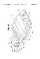
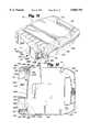
- the AED 10has a front side 112 with a carrying handle 114 formed thereon.
- the opposed rear side 116includes the battery pack compartment 118.
- the battery pack compartment 118is an enclosure 120 defined by top wall 122, opposed bottom wall 124, latch sidewall 126, hinge sidewall 128, and floor 130.
- the AED 10is formed of a top half 132 and a bottom half 134 joined along a mating juncture 136.
- connecting posts 138comprise screw receivers for joining the top half 132 and the bottom half 134 in cooperation with a screw (not shown) threaded into a bore defined in the upper margin of the connecting posts 138.
- the latch sidewall 126has a perpendicular wall portion 140 (FIG. 12) that is disposed generally perpendicular to floor 130 and is coupled thereto.
- An angled wall portion 142extends outwardly from the perpendicular wall portion 140.
- a latch catch 144is formed proximate the distal end of the angled wall portion 142.
- the hinged sidewall 128(FIGS. 7 and 12) includes a recessed receiver 146 defined in part by top wall 122 and bottom wall 124 in conjunction with the perpendicular wall portion 148 (perpendicular to floor 130) and parallel wall portion 150 (parallel to floor 130) of the hinge sidewall 128.
- the hinge sidewall 128includes a second perpendicular wall portion 152 (perpendicular to floor 130) extending outward from the parallel wall portion 150.
- the first and second battery-installed detector electrodes 154a, 154bare disposed in the floor 130 of the battery pack compartment 118. As depicted in FIGS. 8 and 9, electrodes 154a, 154b have a lower end that is fixedly coupled to the floor 130 with the upper, distal end thereof being free of engagement therewith.
- the electrodes 154a, 154bare preferably made of a resilient, deflectable metallic material.
- the electrodes 154a, 154bare deflectable with respect to the fixed lower end thereof. Further, the electrodes 154a, 154b are biased outward from the lower fixed end, such that the electrodes 154a, 154b resist a force tending to move them toward the floor 130.
- the electrodes 154a, 154bare preferably disposed proximate the latch sidewall 126 of the battery pack compartment 118.
- the electrodes 154a, 154bare in electrical communication with the electronic components of the AED 10, including the processor 74, described above in conjunction with AED 10.
- the electrodes 154a, 154bare spaced apart such that the electrodes 154a, 154b are not in electrical communication with each other.
- the main battery electrodes 156a, 156bare also disposed in floor 130 of the battery pack compartment 118.
- the main battery electrodes 156a, 156bare proximate the hinge sidewall 128 of the battery pack compartment 118.
- the electrodes 156a, 156bhave a fixed (proximate) end 158 fixedly disposed within a recess 160 defined in the floor 130.
- the distal end 162 of each of the main battery electrodes 156a, 156bis free of engagement. Further, the distal end 162 of each of the main battery electrodes 156a, 156b is preferably radiused, forming a curved electrical contact surface.
- the curved electrical contact surface of the distal end 162 of the main battery electrodes 156a, 156bis biased outward away from the floor 130.
- the main battery electrodes 156a, 156bare preferably formed of a resilient, deflectable metallic material.
- the electrodes 156a, 156bare deflectable with respect to the fixed end 158 thereof.
- the main battery electrodes 156a, 156bare in electrical communication with the electronic components of the AED 10, including the processor 74.
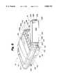
- the battery pack of the present inventionis shown generally at 16 in FIGS. 6-12, 14, and 15.
- the battery pack 16has a case 202 that is formed of case halves 204, 206 fixedly joined at a mating juncture 207.
- the battery pack 16has a latch end 208, a hinge end 210, a forward face 212 and a rear face 214.
- the forward face 212faces inward with respect to the battery pack compartment 118 and is disposed proximate and substantially parallel to the floor 130 of the battery pack compartment 118 when in the engaged disposition with the AED 10, the engaged disposition being depicted in FIG. 12.
- the latch end 208 of the battery pack 16has a generally planar end wall 216 that is formed as a part of the case half 206.
- a latch 218is formed integral with the case half 206 and extends alongside but is spaced apart from the end wall 216.
- the latch 218has a generally planar latch plate 220.
- the latch plate 220has a groove 221 defined therein proximate the point of connection to the case half 206.
- a pair of outwardly extending ribs 222are formed at the opposed sides of the latch plate 220.
- a catch face 224is formed generally transverse to the plane of the latch plate 220 and extending between the ribs 222.
- An actuator tab 226forms the distal end of the latch 218.
- the actuator tab 226has a finger groove 228 formed therein to facilitate compressing the latch 218 against a bias designed into the latch 218. Such compression facilitates disengaging the catch face 224 of the latch 218 from the latch catch 144 for removal of the battery pack 16 from the AED 10.
- the hinge end 210 of the battery pack 16has a receiver insert 230 formed thereon.
- the receiver insert 230has a generally rounded outer surface and is designed to be received within the receiver 146 of the AED 10.
- An end wall 232extends outward from the receiver insert 230 and is preferably generally parallel to the end wall 216 of the latch end 208.
- the forward face 212 of the case 202 of the battery pack 16has a generally planar portion 234 extending from the latch end 208 to a position proximate the receiver insert 230.
- the planar portion 234has an access panel 236 that may be removed to gain access to the plurality of battery cells disposed within the battery pack 16.
- a plate recess 238is formed in the planar portion 234 proximate the latch end 208.
- a preferably metallic conductor plate 240is disposed within the plate recess 238. When the battery pack 16 is in the engaged disposition with the AED 10, the conductor plate 240 is in registry with the battery-installed detector electrodes 154a, 154b.
- the conductor plate 240is formed of an electrically conductive material and is in electrical communication with both the battery-installed detector electrodes 154a, 154b.
- the conductor plate 240completes an electrical circuit between the battery-installed detector electrodes 154a and 154b.
- An inclined portion 242 of the forward face 212extends from the planar portion 234 to the receiver insert 230.
- the inclined portion 242has at least two electrodes 244a, 244b disposed thereon.
- the electrodes 244a, 244bare in electrical communication with the battery cells disposed within the battery pack 16.
- the electrodes 244a, 244bare preferably generally elongate, flat metallic strips and are disposed between electrode rib separators 246, formed in the inclined portion 242. When the battery pack 16 is in the engaged disposition with the AED 10, the electrodes 244a, 244b are in registry with the main battery electrodes 156a, 156b.
- the electrode 244ais in electrical communication with the main battery electrode 156a and the electrode 244b is in electrical communication with the main battery electrode 156b when in such disposition.
- a pair of end guides 248are disposed on one side of the electrodes 244a, 244b.
- the battery pack 16is moved with respect to the AED 10 as indicated by Arrow A in FIG. 17. Such movement brings the battery pack 16 first into a position as depicted in FIG. 9 and then into a disposition as depicted in FIG. 11. In the disposition as depicted in FIG. 9, the receiver insert 230 is partially received within the receiver 146. In this disposition, the battery-installed detector electrodes 154a, 154b are not in contact with the conductor plate 240 and the main battery electrodes 156a, 156b are not in electrical contact with the electrodes 244a, 244b.
- the battery packis rotated into the battery pack compartment 118 defined in the rear side 116 of the AED 10 as indicated by the Arrow B.
- the main battery electrodes 156a, 156bmake electrical contact with the electrodes 244a, 244b and electrical power could be provided by the battery pack 16 to the processor 74 in the AED 10.
- the battery-installed detector electrodes 254a, 254bare still not in electrical contact with the conductor plate 240.
- FIG. 12depicts the battery pack 16 in operable engagement with the AED 10.
- the latch 218is compressed toward the end wall 216 by the action of the ribs 222 riding on the latch sidewall 126 of the battery pack compartment 118.
- the catch face 224 of the latch 218clears the latch catch 144 of the latch sidewall 126, the resilient latch 218 snaps outward with the catch face 224 thereof engaging at the latch catch 144.
- the conductor plate 240is in both compressive and electrical contact with the battery-installed detector electrodes 154a, 154b.
- This contacthas two functions. First, the conductor plate 240 functions as a switch making an electrical contact between the battery-installed detector electrodes 154a, 154b. Second, by being in compressive engagement therewith, the battery-installed detector electrodes 154a, 154b, exert an outwardly directed bias on the battery pack 16, thereby preventing the battery pack 16 from rattling within the battery pack compartment 118.
- the main battery electrodes 156a, 156bare in electrical communication with the electrodes 244a, 244b of the battery pack 16. Accordingly, the battery pack 16 is disposed such that energy is available to the AED 10.
- the finger groove 228is engaged and depressed to bring the latch 218 closer to the end wall 216.
- the battery pack 16may be rotated out of the battery pack compartment 118 by a rotational motion opposite to that as indicated by Arrow B in FIG. 11.
- Such rotational motionprogressively electrically disengages the battery pack 16 from the AED 10.
- the first bit of such rotationbreaks the engagement between the conductor plate 240 and the battery-installed detector electrodes 154a, 154b. This breaks the circuit that existed between the battery-installed detector electrodes 154a and the battery-installed detector electrodes 154b.
- Such opening of the previously existing circuitprovides an anticipatory indication to the processor 74 that disengagement of the battery pack from the AED is imminent. This condition is schematically depicted in FIG. 13.
- the main battery electrodes 156a, 156bare still in electrical communication with the electrodes 244a, 244b of the battery pack 16. Accordingly, energy is still being supplied from the battery pack 16 to the processor 74 of the AED 10.
- the processor 74In the usual rotation of the battery pack 16 out of the battery pack compartment 118, there is at least a 40 millisecond period of time between when the electrical circuit between the battery-installed detector electrodes 154a, 154b is broken and when the main battery electrodes 156a, 156b are disengaged from the electrodes 244a, 244b.
- the processor 74is still powered and detects that the battery is no longer installed. The processor 74 then commands the high voltage board to dump all charges existing in the high voltage capacitors.
- This dumpis accomplished on an orderly basis in such 40 millisecond period before the disengagement of the main battery electrodes 156a, 156b and electrodes 244a, 244b under power of the battery pack 16.
- the processor 74 of the AED 10goes dead for lack of power from the battery pack 16.
Landscapes
- Health & Medical Sciences (AREA)
- Cardiology (AREA)
- Heart & Thoracic Surgery (AREA)
- Engineering & Computer Science (AREA)
- Biomedical Technology (AREA)
- Nuclear Medicine, Radiotherapy & Molecular Imaging (AREA)
- Radiology & Medical Imaging (AREA)
- Life Sciences & Earth Sciences (AREA)
- Animal Behavior & Ethology (AREA)
- General Health & Medical Sciences (AREA)
- Public Health (AREA)
- Veterinary Medicine (AREA)
- Electrotherapy Devices (AREA)
Abstract
Description
Claims (20)
Priority Applications (1)
| Application Number | Priority Date | Filing Date | Title |
|---|---|---|---|
| US09/057,312US5868794A (en) | 1997-04-08 | 1998-04-08 | AED and battery pack with anticipatory battery disengagement detection |
Applications Claiming Priority (3)
| Application Number | Priority Date | Filing Date | Title |
|---|---|---|---|
| US4180797A | 1997-04-08 | 1997-04-08 | |
| US4180797P | 1997-04-08 | 1997-04-08 | |
| US09/057,312US5868794A (en) | 1997-04-08 | 1998-04-08 | AED and battery pack with anticipatory battery disengagement detection |
Publications (1)
| Publication Number | Publication Date |
|---|---|
| US5868794Atrue US5868794A (en) | 1999-02-09 |
Family
ID=27365986
Family Applications (1)
| Application Number | Title | Priority Date | Filing Date |
|---|---|---|---|
| US09/057,312Expired - LifetimeUS5868794A (en) | 1997-04-08 | 1998-04-08 | AED and battery pack with anticipatory battery disengagement detection |
Country Status (1)
| Country | Link |
|---|---|
| US (1) | US5868794A (en) |
Cited By (34)
| Publication number | Priority date | Publication date | Assignee | Title |
|---|---|---|---|---|
| US6185461B1 (en)* | 1998-07-01 | 2001-02-06 | Pacesetter, Inc. | System and method for verification of recommended replacement time indication in an implantable cardiac stimulation device |
| US6223077B1 (en)* | 1998-01-26 | 2001-04-24 | Physio-Control Manufacturing Corporation | Automatic power switching in a defibrillator |
| US6329822B1 (en) | 2000-02-11 | 2001-12-11 | Daniel J. Powers | Periodic automatic self-test system and methodology |
| US6356785B1 (en) | 1997-11-06 | 2002-03-12 | Cecily Anne Snyder | External defibrillator with CPR prompts and ACLS prompts and methods of use |
| USD459298S1 (en) | 2001-06-29 | 2002-06-25 | Medtronic Physio-Control Manufacturing Corp. | Defibrillator charging pack |
| US6438415B1 (en) | 1999-10-01 | 2002-08-20 | Daniel J Powers | Method and apparatus for controlling the operation and functionality of an electrotherapy device |
| US6473058B1 (en)* | 1999-03-31 | 2002-10-29 | Minolta Co., Ltd. | Information display device and display control method |
| US6577102B1 (en) | 2001-09-21 | 2003-06-10 | Defibtech Llc | Medical device battery system including a secondary power supply |
| US6586850B1 (en) | 2000-07-05 | 2003-07-01 | Koninklijke Philips Electronics N.V. | Device with multiple, concurrently-installed power molecules and method for controlling same |
| US20030123240A1 (en)* | 2001-12-28 | 2003-07-03 | Medtronic Physio-Control Manufacturing Corporation | Circuit package and method for making the same |
| US6602635B1 (en)* | 1999-09-01 | 2003-08-05 | Nokia Mobile Phones Ltd. | Method and arrangement for anticipating disengagement moment of battery package of battery-operated electronic device, and battery-operated electronic device |
| US6609026B2 (en)* | 1998-11-09 | 2003-08-19 | Koninklijke Philips Electronics N.V. | Carrying case for defibrillator |
| US6662056B2 (en)* | 2000-12-22 | 2003-12-09 | Koninklijke Philips Electronics N.V. | Cartridge for storing an electrode pad |
| US6665176B2 (en)* | 2001-06-04 | 2003-12-16 | Ge Medical Systems Global Technology Company, Llc | Electronic device |
| USD490370S1 (en) | 2003-09-17 | 2004-05-25 | Koninklijke Philips Electronics N.V. | Automatic external defibrillator battery pack |
| US20040111122A1 (en)* | 2000-11-13 | 2004-06-10 | Medtronic Physio-Control Manufacturing Corp. | Defibrillator with a multiple-mode interface |
| US20040133244A1 (en)* | 2001-09-21 | 2004-07-08 | Vaisnys Gintaras A. | Automatic external defibrillator with active status indicator |
| USD499183S1 (en) | 2003-10-01 | 2004-11-30 | Defibtech, Llc | Enclosure for an automatic external defibrillator |
| US20040267322A1 (en)* | 2003-06-27 | 2004-12-30 | Medtronic Physio-Control Corp. | Portable defibrillator with bypass line power emergency charging of capacitor |
| US20050075671A1 (en)* | 2003-10-02 | 2005-04-07 | Vaisnys Gintaras A. | External defibrillator enclosure with accessory storage slot |
| US6955864B1 (en) | 2001-09-21 | 2005-10-18 | Defibtech, Llc | Medical device battery pack with active status indication |
| US20060259080A1 (en)* | 2005-03-21 | 2006-11-16 | Defibtech, Llc | System and method for presenting defibrillator status information while in standby mode |
| US20080136652A1 (en)* | 2006-03-21 | 2008-06-12 | Defibtech, Llc | System and Method for Effectively Indicating Element Failure or a Preventive Maintenance Condition in an Automatic External Defibrillator (AED) |
| FR2923096A1 (en)* | 2007-10-30 | 2009-05-01 | Yves Faisandier | Rechargeable cell housing and autonomous electronic system associating device for e.g. autonomous electrocardiogram recorder, has trap taking closed-starting position to drive change of switch state to control exit point of consumption mode |
| US7548781B2 (en) | 2005-03-21 | 2009-06-16 | Defibtech, Llc | Environmentally responsive active status indicator system and method |
| US20090187225A1 (en)* | 2005-03-21 | 2009-07-23 | Defibtech, Llc | PCB blade connector system and method |
| US20110074594A1 (en)* | 2009-09-29 | 2011-03-31 | Tyco Healthcare Group Lp | Battery Assembly With Alarm |
| USD663264S1 (en) | 2011-12-07 | 2012-07-10 | Cardiac Science Corporation | Battery |
| USD679017S1 (en)* | 2011-12-07 | 2013-03-26 | Cardiac Science Corporation | Automated external defibrillator |
| USD759249S1 (en) | 2014-10-30 | 2016-06-14 | The American National Red Cross | Electronic device |
| US9987498B2 (en) | 2012-08-20 | 2018-06-05 | Physio-Control, Inc. | Medical device with interactive control panel |
| US20190190293A1 (en)* | 2017-12-19 | 2019-06-20 | Welch Allyn, Inc. | Vital Signs Monitor with a Removable and Dischargable Battery |
| US20240335671A1 (en)* | 2023-01-18 | 2024-10-10 | Bardy Technologies, Inc. | Defibrillator case |
| US20250025709A1 (en)* | 2023-01-18 | 2025-01-23 | Bardy Technologies, Inc. | Defibrillation assembly energizable through magnet removal |
Citations (7)
| Publication number | Priority date | Publication date | Assignee | Title |
|---|---|---|---|---|
| US4590943A (en)* | 1985-04-19 | 1986-05-27 | Physio-Control Corporation | System for providing power to portable defibrillator |
| US4733265A (en)* | 1986-06-13 | 1988-03-22 | Canon Kabushiki Kaisha | Data retaining apparatus for a camera |
| US5224870A (en)* | 1991-01-11 | 1993-07-06 | Physio-Control Corporation | Battery pack |
| US5470343A (en)* | 1994-06-10 | 1995-11-28 | Zmd Corporation | Detachable power supply for supplying external power to a portable defibrillator |
| US5483165A (en)* | 1994-01-14 | 1996-01-09 | Heartstream, Inc. | Battery system and method for determining a battery condition |
| WO1997042669A1 (en)* | 1996-05-06 | 1997-11-13 | Physio-Control Corporation | Keyed self-latching battery pack for a portable defibrillator |
| US5762512A (en)* | 1995-10-12 | 1998-06-09 | Symbol Technologies, Inc. | Latchable battery pack for battery-operated electronic device having controlled power shutdown and turn on |
- 1998
- 1998-04-08USUS09/057,312patent/US5868794A/ennot_activeExpired - Lifetime
Patent Citations (9)
| Publication number | Priority date | Publication date | Assignee | Title |
|---|---|---|---|---|
| US4590943A (en)* | 1985-04-19 | 1986-05-27 | Physio-Control Corporation | System for providing power to portable defibrillator |
| US4733265A (en)* | 1986-06-13 | 1988-03-22 | Canon Kabushiki Kaisha | Data retaining apparatus for a camera |
| US5224870A (en)* | 1991-01-11 | 1993-07-06 | Physio-Control Corporation | Battery pack |
| US5350317A (en)* | 1991-01-11 | 1994-09-27 | Physio-Control Corporation | Battery pack |
| US5483165A (en)* | 1994-01-14 | 1996-01-09 | Heartstream, Inc. | Battery system and method for determining a battery condition |
| US5470343A (en)* | 1994-06-10 | 1995-11-28 | Zmd Corporation | Detachable power supply for supplying external power to a portable defibrillator |
| US5762512A (en)* | 1995-10-12 | 1998-06-09 | Symbol Technologies, Inc. | Latchable battery pack for battery-operated electronic device having controlled power shutdown and turn on |
| WO1997042669A1 (en)* | 1996-05-06 | 1997-11-13 | Physio-Control Corporation | Keyed self-latching battery pack for a portable defibrillator |
| US5741305A (en)* | 1996-05-06 | 1998-04-21 | Physio-Control Corporation | Keyed self-latching battery pack for a portable defibrillator |
Cited By (72)
| Publication number | Priority date | Publication date | Assignee | Title |
|---|---|---|---|---|
| US6356785B1 (en) | 1997-11-06 | 2002-03-12 | Cecily Anne Snyder | External defibrillator with CPR prompts and ACLS prompts and methods of use |
| US6223077B1 (en)* | 1998-01-26 | 2001-04-24 | Physio-Control Manufacturing Corporation | Automatic power switching in a defibrillator |
| US6185461B1 (en)* | 1998-07-01 | 2001-02-06 | Pacesetter, Inc. | System and method for verification of recommended replacement time indication in an implantable cardiac stimulation device |
| US6609026B2 (en)* | 1998-11-09 | 2003-08-19 | Koninklijke Philips Electronics N.V. | Carrying case for defibrillator |
| US6473058B1 (en)* | 1999-03-31 | 2002-10-29 | Minolta Co., Ltd. | Information display device and display control method |
| US6602635B1 (en)* | 1999-09-01 | 2003-08-05 | Nokia Mobile Phones Ltd. | Method and arrangement for anticipating disengagement moment of battery package of battery-operated electronic device, and battery-operated electronic device |
| US6438415B1 (en) | 1999-10-01 | 2002-08-20 | Daniel J Powers | Method and apparatus for controlling the operation and functionality of an electrotherapy device |
| US6329822B1 (en) | 2000-02-11 | 2001-12-11 | Daniel J. Powers | Periodic automatic self-test system and methodology |
| US6784568B2 (en) | 2000-07-05 | 2004-08-31 | Koninklijke Philips Electronics N.V. | Device with multiple, concurrently-installed power modules and method for controlling same |
| US6586850B1 (en) | 2000-07-05 | 2003-07-01 | Koninklijke Philips Electronics N.V. | Device with multiple, concurrently-installed power molecules and method for controlling same |
| US20040111122A1 (en)* | 2000-11-13 | 2004-06-10 | Medtronic Physio-Control Manufacturing Corp. | Defibrillator with a multiple-mode interface |
| US6920354B2 (en) | 2000-11-13 | 2005-07-19 | Medtronic Physio-Control Manufacturing Corp. | Defibrillator with a multiple-mode interface |
| US6754526B2 (en)* | 2000-11-13 | 2004-06-22 | Medtronic Physio-Control Corp | Defibrillator with a multiple-mode interface |
| US6662056B2 (en)* | 2000-12-22 | 2003-12-09 | Koninklijke Philips Electronics N.V. | Cartridge for storing an electrode pad |
| US6665176B2 (en)* | 2001-06-04 | 2003-12-16 | Ge Medical Systems Global Technology Company, Llc | Electronic device |
| USD459298S1 (en) | 2001-06-29 | 2002-06-25 | Medtronic Physio-Control Manufacturing Corp. | Defibrillator charging pack |
| US8494628B2 (en) | 2001-09-21 | 2013-07-23 | Defibtech, Llc | Automatic external defibrillator with active status indicator |
| US20110190839A1 (en)* | 2001-09-21 | 2011-08-04 | Defibtech, Llc | Automatic External Defibrillator with Active Status Indicator |
| US7855010B2 (en) | 2001-09-21 | 2010-12-21 | Defibtech Llc | Medical device battery pack |
| US20110190837A1 (en)* | 2001-09-21 | 2011-08-04 | Defibtech, Llc | Automatic External Defibrillator with Active Status Indicator |
| US20100075208A1 (en)* | 2001-09-21 | 2010-03-25 | Defibtech, Llc | Medical Device Battery Pack with Active Status Indication |
| US6577102B1 (en) | 2001-09-21 | 2003-06-10 | Defibtech Llc | Medical device battery system including a secondary power supply |
| US7625662B2 (en) | 2001-09-21 | 2009-12-01 | Defibtech, Llc | Medical device battery back system and method for providing active status indication |
| US20110190838A1 (en)* | 2001-09-21 | 2011-08-04 | Defibtech, Llc | Automatic External Defibrillator with Active Status Indicator |
| US6955864B1 (en) | 2001-09-21 | 2005-10-18 | Defibtech, Llc | Medical device battery pack with active status indication |
| US20050256546A1 (en)* | 2001-09-21 | 2005-11-17 | Vaisnys Gintaras A | Medical device battery pack with active status indication |
| US8498701B2 (en) | 2001-09-21 | 2013-07-30 | Defibtech, LLP | Automatic external defibrillator with active status indicator |
| US7930023B2 (en)* | 2001-09-21 | 2011-04-19 | Defibtech, Llc | Automatic external defibrillator with active status indicator |
| US7495413B2 (en) | 2001-09-21 | 2009-02-24 | Defibtech Llc | Medical device battery system including a secondary power supply |
| US8343644B2 (en) | 2001-09-21 | 2013-01-01 | Defibtech, Llc | Medical device with a multiple function battery status indicator |
| US8224441B2 (en) | 2001-09-21 | 2012-07-17 | Defibtech, Llc | Automatic external defibrillator with active status indicator |
| US20040133244A1 (en)* | 2001-09-21 | 2004-07-08 | Vaisnys Gintaras A. | Automatic external defibrillator with active status indicator |
| US20030123240A1 (en)* | 2001-12-28 | 2003-07-03 | Medtronic Physio-Control Manufacturing Corporation | Circuit package and method for making the same |
| US6885562B2 (en) | 2001-12-28 | 2005-04-26 | Medtronic Physio-Control Manufacturing Corporation | Circuit package and method for making the same |
| US20040267322A1 (en)* | 2003-06-27 | 2004-12-30 | Medtronic Physio-Control Corp. | Portable defibrillator with bypass line power emergency charging of capacitor |
| USD490370S1 (en) | 2003-09-17 | 2004-05-25 | Koninklijke Philips Electronics N.V. | Automatic external defibrillator battery pack |
| USD499183S1 (en) | 2003-10-01 | 2004-11-30 | Defibtech, Llc | Enclosure for an automatic external defibrillator |
| US8014859B2 (en)* | 2003-10-02 | 2011-09-06 | Defibtech, Llc | External defibrillator enclosure with accessory storage slot |
| US20050075671A1 (en)* | 2003-10-02 | 2005-04-07 | Vaisnys Gintaras A. | External defibrillator enclosure with accessory storage slot |
| US20100069981A1 (en)* | 2005-03-21 | 2010-03-18 | Defibtech, Llc | System and Method for Presenting Defibrillator Status Information While in Standby Mode |
| US20090187225A1 (en)* | 2005-03-21 | 2009-07-23 | Defibtech, Llc | PCB blade connector system and method |
| US7912543B2 (en) | 2005-03-21 | 2011-03-22 | Defibtech, Llc | PCB blade connector system and method |
| US7953478B2 (en) | 2005-03-21 | 2011-05-31 | Defibtech, Llc | System and method for presenting defibrillator status information while in standby mode |
| US20100168811A1 (en)* | 2005-03-21 | 2010-07-01 | Defibtech, Llc | Identifying the Usage Status of a Defibrillation Pad Assembly |
| US7627372B2 (en) | 2005-03-21 | 2009-12-01 | Defibtech, Llc | System and method for presenting defibrillator status information while in standby mode |
| US20090233458A1 (en)* | 2005-03-21 | 2009-09-17 | Defibtech, Llc | PCB blade connector system and method |
| US8280506B2 (en) | 2005-03-21 | 2012-10-02 | Defibtech, Llc | PCB blade connector system and method |
| US20110213262A1 (en)* | 2005-03-21 | 2011-09-01 | Defibtech, Llc | Method for Presenting Current and Stored ECG Waveforms on a Portable, External Defibrillator |
| US7548781B2 (en) | 2005-03-21 | 2009-06-16 | Defibtech, Llc | Environmentally responsive active status indicator system and method |
| US20060259080A1 (en)* | 2005-03-21 | 2006-11-16 | Defibtech, Llc | System and method for presenting defibrillator status information while in standby mode |
| US8774916B2 (en) | 2005-03-21 | 2014-07-08 | Defibtech, Llc | PCB blade connector system and method |
| US8185196B2 (en) | 2005-03-21 | 2012-05-22 | Defibtech, Llc | PCB blade connector system and method |
| US8185197B2 (en) | 2005-03-21 | 2012-05-22 | Defibtech, Llc | Identifying the usage status of a defibrillation pad assembly |
| US8116863B2 (en) | 2006-03-21 | 2012-02-14 | Defibtech, Llc | System and method for effectively indicating element failure or a preventive maintenance condition in an automatic external defibrillator (AED) |
| US8386035B2 (en) | 2006-03-21 | 2013-02-26 | Defibtech, Llc | System and method for effectively indicating element failure or a preventive maintenance condition in an automatic external defibrillator (AED) |
| US20110213433A1 (en)* | 2006-03-21 | 2011-09-01 | Defibtech, Llc | System and Method for Effectively Indicating Element Failure or a Preventive Maintenance Condition in an Automatic External Defibrillator (AED) |
| US20080136652A1 (en)* | 2006-03-21 | 2008-06-12 | Defibtech, Llc | System and Method for Effectively Indicating Element Failure or a Preventive Maintenance Condition in an Automatic External Defibrillator (AED) |
| FR2923096A1 (en)* | 2007-10-30 | 2009-05-01 | Yves Faisandier | Rechargeable cell housing and autonomous electronic system associating device for e.g. autonomous electrocardiogram recorder, has trap taking closed-starting position to drive change of switch state to control exit point of consumption mode |
| US20110074594A1 (en)* | 2009-09-29 | 2011-03-31 | Tyco Healthcare Group Lp | Battery Assembly With Alarm |
| US8730053B2 (en) | 2009-09-29 | 2014-05-20 | Covidien Lp | Battery assembly with alarm |
| US8179276B2 (en)* | 2009-09-29 | 2012-05-15 | Tyco Healthcare Group Lp | Battery assembly with alarm |
| US8373572B2 (en) | 2009-09-29 | 2013-02-12 | Covidien Lp | Battery assembly with alarm |
| USD679017S1 (en)* | 2011-12-07 | 2013-03-26 | Cardiac Science Corporation | Automated external defibrillator |
| USD663264S1 (en) | 2011-12-07 | 2012-07-10 | Cardiac Science Corporation | Battery |
| US9987498B2 (en) | 2012-08-20 | 2018-06-05 | Physio-Control, Inc. | Medical device with interactive control panel |
| USD759249S1 (en) | 2014-10-30 | 2016-06-14 | The American National Red Cross | Electronic device |
| US20190190293A1 (en)* | 2017-12-19 | 2019-06-20 | Welch Allyn, Inc. | Vital Signs Monitor with a Removable and Dischargable Battery |
| EP3501386A1 (en)* | 2017-12-19 | 2019-06-26 | Welch Allyn, INC. | Vital signs monitor with a removable and dischargable battery |
| CN110025307A (en)* | 2017-12-19 | 2019-07-19 | 伟伦公司 | With can be removed and can discharge battery vital sign monitor |
| US11251635B2 (en)* | 2017-12-19 | 2022-02-15 | Welch Allyn, Inc. | Vital signs monitor with a removable and dischargable battery |
| US20240335671A1 (en)* | 2023-01-18 | 2024-10-10 | Bardy Technologies, Inc. | Defibrillator case |
| US20250025709A1 (en)* | 2023-01-18 | 2025-01-23 | Bardy Technologies, Inc. | Defibrillation assembly energizable through magnet removal |
Similar Documents
| Publication | Publication Date | Title |
|---|---|---|
| US5868794A (en) | AED and battery pack with anticipatory battery disengagement detection | |
| US6668192B1 (en) | Automated external defibrilator with the ability to store rescue information | |
| EP0756878B1 (en) | Automated external defribillator | |
| US5797969A (en) | One button lid activated automatic external defibrillator | |
| US5897576A (en) | Automated external defibrillator with the ability to sense temperature | |
| US6083246A (en) | Lid open detection circuit for automated external defibrillators | |
| US8494628B2 (en) | Automatic external defibrillator with active status indicator | |
| US5955956A (en) | Audible alarm system for an automated external defibrillator | |
| US6366809B1 (en) | Defibrillator battery with memory and status indication guage | |
| US6125298A (en) | Defibrillation system for pediatric patients | |
| US9008767B2 (en) | System and method for performing self-test in an automatic external defribillator (AED) | |
| US5697955A (en) | Defibrillator electrodes and date code detector circuit | |
| US5700281A (en) | Stage and state monitoring automated external defibrillator | |
| US4610254A (en) | Interactive portable defibrillator | |
| US4619265A (en) | Interactive portable defibrillator including ECG detection circuit | |
| US6088616A (en) | Field programmable automated external defibrillator | |
| US10426965B2 (en) | Method and apparatus for determining battery capacity in a defibrillator | |
| EP0757912B1 (en) | Automated external defibrillator with self-test system | |
| US20040267322A1 (en) | Portable defibrillator with bypass line power emergency charging of capacitor | |
| WO1997043000A1 (en) | Defibrillator electrode circuitry | |
| WO1998044989A1 (en) | Automated external defibrillator battery memory, dual cell, and removable configurations | |
| EP1637181A1 (en) | Automated external defibrillator | |
| EP1419798A2 (en) | Automated external defibrillator | |
| WO1998044988A1 (en) | Field programmable automated external defibrillator | |
| HK1067565A (en) | Automated external defibrillator |
Legal Events
| Date | Code | Title | Description |
|---|---|---|---|
| AS | Assignment | Owner name:SURVIVALINK CORPORATION, MINNESOTA Free format text:ASSIGNMENT OF ASSIGNORS INTEREST;ASSIGNORS:BARKLEY, STEVEN D.;JOHNSON, ROBERT K.;REEL/FRAME:009083/0509 Effective date:19980407 | |
| STCF | Information on status: patent grant | Free format text:PATENTED CASE | |
| FPAY | Fee payment | Year of fee payment:4 | |
| AS | Assignment | Owner name:HSBC BANK, USA, NEW YORK Free format text:SECURITY AGREEMENT;ASSIGNOR:CARDIAC SCIENCE, INC.;REEL/FRAME:013146/0001 Effective date:20020530 | |
| AS | Assignment | Owner name:CARDIAC SCIENCE, INC., MINNESOTA Free format text:ASSIGNMENT OF ASSIGNORS INTEREST;ASSIGNOR:SURVIVALINK CORPORATION;REEL/FRAME:013280/0068 Effective date:20020718 | |
| FEPP | Fee payment procedure | Free format text:PAT HOLDER NO LONGER CLAIMS SMALL ENTITY STATUS, ENTITY STATUS SET TO UNDISCOUNTED (ORIGINAL EVENT CODE: STOL); ENTITY STATUS OF PATENT OWNER: LARGE ENTITY | |
| REFU | Refund | Free format text:REFUND - PAYMENT OF MAINTENANCE FEE, 8TH YR, SMALL ENTITY (ORIGINAL EVENT CODE: R2552); ENTITY STATUS OF PATENT OWNER: LARGE ENTITY | |
| FPAY | Fee payment | Year of fee payment:8 | |
| AS | Assignment | Owner name:CARDIAC SCIENCE CORPORATION, WASHINGTON Free format text:MERGER;ASSIGNOR:CARDIAC SCIENCE, INC.;REEL/FRAME:018291/0818 Effective date:20060224 | |
| AS | Assignment | Owner name:SILICON VALLEY BANK,CALIFORNIA Free format text:SECURITY AGREEMENT;ASSIGNOR:CARDIAC SCIENCE, INC.;REEL/FRAME:024492/0931 Effective date:20100607 Owner name:SILICON VALLEY BANK, CALIFORNIA Free format text:SECURITY AGREEMENT;ASSIGNOR:CARDIAC SCIENCE, INC.;REEL/FRAME:024492/0931 Effective date:20100607 | |
| FPAY | Fee payment | Year of fee payment:12 | |
| AS | Assignment | Owner name:CARDIAC SCIENCE CORPORATION, WASHINGTON Free format text:RELEASE BY SECURED PARTY;ASSIGNOR:SILICON VALLEY BANK;REEL/FRAME:029389/0937 Effective date:20121012 | |
| AS | Assignment | Owner name:DBS BANK LTD., BANGALORE BRANCH, INDIA Free format text:SECURITY AGREEMENT;ASSIGNOR:CARDIAC SCIENCE CORPORATION;REEL/FRAME:029733/0469 Effective date:20121228 | |
| AS | Assignment | Owner name:CARD-SCI INC., CALIFORNIA Free format text:ASSIGNMENT OF ASSIGNORS INTEREST;ASSIGNOR:CARDIAC SCIENCE CORPORATION;REEL/FRAME:037627/0418 Effective date:20160125 | |
| AS | Assignment | Owner name:THE PRIVATEBANK AND TRUST COMPANY, ILLINOIS Free format text:SECURITY INTEREST;ASSIGNOR:CARD-SCI INC.;REEL/FRAME:037689/0592 Effective date:20160125 | |
| AS | Assignment | Owner name:CARD-SCI INC., CALIFORNIA Free format text:CORRECTIVE ASSIGNMENT TO CORRECT THE PATENT NO. 6143233 THAT WAS INCORRECTLY ASSIGNED PREVIOUSLY RECORDED ON REEL 037627 FRAME 0418. ASSIGNOR(S) HEREBY CONFIRMS THE THE CORRECT PATENT NUMBER IS 6148233;ASSIGNOR:CARDIAC SCIENCE CORPORATION;REEL/FRAME:037783/0215 Effective date:20160125 Owner name:CARDIAC SCIENCE CORPORATION, WISCONSIN Free format text:CHANGE OF NAME;ASSIGNOR:CARD-SCI INC.;REEL/FRAME:037793/0106 Effective date:20160126 | |
| AS | Assignment | Owner name:CARDIAC SCIENCE CORPORATION, WISCONSIN Free format text:CHANGE OF NAME;ASSIGNOR:CARD-SCI INC.;REEL/FRAME:037897/0952 Effective date:20160126 | |
| AS | Assignment | Owner name:CARDIAC SCIENCE CORPORATION, WISCONSIN Free format text:RELEASE BY SECURED PARTY;ASSIGNOR:CIBC BANK USA (FKA THE PRIVATEBANK AND TRUST COMPANY);REEL/FRAME:050300/0804 Effective date:20190826 | |
| AS | Assignment | Owner name:ZOLL MEDICAL CORPORATION, MASSACHUSETTS Free format text:ASSIGNMENT OF ASSIGNORS INTEREST;ASSIGNOR:CARDIAC SCIENCE CORPORATION;REEL/FRAME:056391/0439 Effective date:20210409 |