US5868792A - Environment-response method for maintaining electronic device such as an external defibrillator - Google Patents
Environment-response method for maintaining electronic device such as an external defibrillatorDownload PDFInfo
- Publication number
- US5868792A US5868792AUS08/912,034US91203497AUS5868792AUS 5868792 AUS5868792 AUS 5868792AUS 91203497 AUS91203497 AUS 91203497AUS 5868792 AUS5868792 AUS 5868792A
- Authority
- US
- United States
- Prior art keywords
- self
- test
- temperature
- environmental condition
- predetermined range
- Prior art date
- Legal status (The legal status is an assumption and is not a legal conclusion. Google has not performed a legal analysis and makes no representation as to the accuracy of the status listed.)
- Expired - Lifetime
Links
Images


Classifications
- A—HUMAN NECESSITIES
- A61—MEDICAL OR VETERINARY SCIENCE; HYGIENE
- A61N—ELECTROTHERAPY; MAGNETOTHERAPY; RADIATION THERAPY; ULTRASOUND THERAPY
- A61N1/00—Electrotherapy; Circuits therefor
- A61N1/18—Applying electric currents by contact electrodes
- A61N1/32—Applying electric currents by contact electrodes alternating or intermittent currents
- A61N1/38—Applying electric currents by contact electrodes alternating or intermittent currents for producing shock effects
- A61N1/39—Heart defibrillators
- A61N1/3925—Monitoring; Protecting
- A—HUMAN NECESSITIES
- A61—MEDICAL OR VETERINARY SCIENCE; HYGIENE
- A61N—ELECTROTHERAPY; MAGNETOTHERAPY; RADIATION THERAPY; ULTRASOUND THERAPY
- A61N1/00—Electrotherapy; Circuits therefor
- A61N1/18—Applying electric currents by contact electrodes
- A61N1/32—Applying electric currents by contact electrodes alternating or intermittent currents
- A61N1/38—Applying electric currents by contact electrodes alternating or intermittent currents for producing shock effects
- A61N1/39—Heart defibrillators
- A61N1/3904—External heart defibrillators [EHD]
Definitions
- This inventionrelates generally to electronic devices and environment-dependent methods of maintaining the devices and indicating operational status of the devices.
- this inventionrelates to temperature-dependent methods of maintaining external defibrillators and indicating their operational status.
- Electronic devices that are infrequently usedmay be designed to perform automatic self-tests on a preset schedule, in response to an event or condition, or otherwise and to indicate the results of those self-tests to a potential user.
- An examplecan be found in certain external defibrillators that automatically self-test battery capacity and other defibrillator functions and components and indicate the results of those self-tests (i.e., the device's operational status) through visual displays and/or audible tones.
- U.S. patent application Ser. No. 08/240,272describes a battery-operated automatic external defibrillator (AED) designed for infrequent use.
- AEDautomatic external defibrillator
- the device described in that patent applicationperforms a variety of daily, weekly and monthly self-tests while in stand-by mode (i.e., when not powered-on to treat a patient, to review past treatment events, etc.) and indicates the operational status of the device using an "OK” or "Not OK" fail-safe display and through an audible tone generator.
- One of the device parameters monitored during the self-testsis remaining battery capacity.
- the '272 applicationalso suggests performing a group of self-tests automatically in response to exposure of the defibrillator to temperature extremes, although the exact nature of the environmentally-triggered self-tests is not disclosed.
- Environmental conditionscan materially affect the manner in which an electronic device operates.
- a device self-test performed outside of a given environmental condition rangecould be inaccurate. It is therefore an object of this invention to take environmental measurements such as ambient temperature into account when operating an electronic device to perform an automatic self-test and when indicating operational status of the device.
- This inventionis a method of maintaining an electronic device, the method including the steps of monitoring an external environmental condition such as temperature or humidity; monitoring a self-test initialization criterion; performing an automatic device self-test if the self-test initialization criterion is met and if the environmental condition is within a predetermined range; and not performing the automatic device self-test if the self-test initialization criterion is met but the environmental condition is outside the predetermined range.
- the method of this inventionfurther includes, after the not performing step, performing the automatic device self-test when the environmental condition returns to the predetermined range after being outside the predetermined range.
- the methodmay also include the step of scheduling an additional automatic device self-test after the environmental condition returns to the predetermined range after being outside the predetermined range.
- the methodincludes, before the performing step, the step of waking the device from a stand-by mode.
- the methodmay also include the step of changing an indication of device operating status if the scheduled automatic device self-test is not performed.
- the method of this inventionincludes the step of changing an indication of device operating status if the environmental condition is outside of the predetermined range.
- the electronic deviceis an external defibrillator.
- FIG. 1shows the major components of an automatically self-testing external defibrillator.
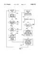
- FIG. 2is a flow chart showing one aspect of this invention.
- FIG. 3is a flow chart showing another aspect of this invention.
- FIG. 4is a schematic drawing of an external defibrillator according to a preferred embodiment of this invention.
- This inventionmay be used in electronic devices that perform one or more automatic self-tests when one or more self-test initialization criteria (such as the passage of time) are met.
- the inventionis particularly useful in battery-operated devices, since operation outside of a prescribed temperature range may be detrimental to battery capacity. While the preferred embodiment of the invention is explained below with respect to an automatically self-testing battery-operated external defibrillator, it should be understood that the invention may be used in other contexts as well.
- an electronic deviceshould not be operated outside of a specified temperature range.
- operation outside of the specified temperature rangemay harm certain temperature-sensitive components of the device.
- external defibrillator 10includes a high voltage delivery system 14 operating under the control of controller 12 to deliver an electric shock to an electrode interface 16.
- the high voltage delivery systemmay include a power transformer, switches and other circuit elements known in the defibrillator art. Power for operating the defibrillator and for the electrical shock comes from battery 24.
- defibrillator 10automatically performs self-tests under the control of a self-test system 18 and indicates its operational status on a status indicator 22.
- the self-testsmay include a battery capacity test and tests of other defibrillator systems or components.
- Status indicator 22may be any object which informs the user of device status through visual, audible, tactile, or other sensory means (e.g., a light, a text display, an electrically or mechanically altered symbol, a beeper, or a spoken word generator).
- the self-test systemmay be an integral part of the controller 12, of course, without departing from the scope of this invention.
- Defibrillator 10has a temperature sensor 20 which can be used to determine whether the ambient temperature is within the defibrillator's specified operating range. Controller 12 may also use temperature sensor 20 to identify warning states or other device operational status and to indicate device status on status indicator 22 in response to a change in temperature (whether or not the defibrillator is within its specified operating range).
- External defibrillator 10has at least three operational modes.
- a controller 12operates a high-voltage delivery system 14 to deliver an electrical shock to a patient through an electrode interface 16.
- controller 12In self-test mode, controller 12 automatically tests one or more of the defibrillator's circuits or functions (such as the defibrillator's battery) in response, e.g., to a request for a self-test from a self-test signal generator 18 and/or a temperature monitor 20 and indicates defibrillator operating status on a status indicator 22. More details about automatic self-tests in external defibrillators may be found in the '272 patent application. The exact nature of the self-tests is not a part of this invention, except as indicated herein.
- controller 12conserves power by simply monitoring temperature and other self-test criteria (such as elapsed or real time) and by watching for a request to use the defibrillator, in which cases the defibrillator will move out of stand-by mode to self-test mode or use mode, respectively.
- Power for the electric shock and for operating the defibrillatoris supplied by a battery 24.
- FIG. 2is a flow chart showing one aspect of this invention.
- FIG. 2shows a method of maintaining an electronic device, such as the external defibrillator of FIG. 1.
- This methodpresumes that the device automatically initiates a self-test according to one or more criteria (such as the passage of time) and indicates the result of the self-test (i.e., the device's operational status) on a status indicator.
- the devicemonitors temperature in block 200 as well as at least one self-test initialization criterion, as in block 202. The device continues to monitor temperature and to watch for the self-test initialization criterion until the self-test initialization criterion is met.
- the devicedetermines at block 206 whether the monitored temperature is within a specified range. If so, the device performs its self-test and indicates the result of the self-test on a status indicator (block 208).
- the devicedoes not perform the self-test. Instead, the device indicates a non-operational status on the status indicator (block 210) to show that the device's true status is uncertain due to its inability to perform a self-test.
- the devicethen continues to monitor temperature and watch for a self-test initialization criterion to be satisfied.
- the self-test initialization criterionmay simply be a return of the monitored temperature to the specified range, in which case the device would proceed to perform its postponed self-test and indicate the result of the test on its status indicator (block 208).
- the self-test initialization criterionneed not be constant. It may change in response to, e.g., the device's inability to perform an earlier self-test due to an out-of-range temperature.
- FIG. 3is a flow chart showing another aspect of this invention's method of maintaining an electronic device such as an external defibrillator.
- the devicemonitors temperature and a self-test initialization criterion (blocks 300-302), as in the FIG. 2 embodiment. If the self-test initialization criterion is met and the monitored temperature is within a specified range, the device performs its automatic self-test and indicates device status as a result of that test on a device status indicator (blocks 304-308). The device then sets a self-test initialization criterion that will trigger a device self-test, such as by scheduling the next self-test (i.e., the initialization criterion is the passage of time) (block 318).
- the deviceindicates a non-operational or warning status on the device's status indicator (block 310) without performing a self-test.
- the devicecontinues to monitor temperature (block 312), and if the monitored temperature enters a specified temperature range (which may be the same temperature range specified in block 306), the device performs the postponed self-test and indicates device status as a result of that test on a device status indicator (block 316).
- the devicesets a self-test initialization criterion that will trigger a device self-test, such as by scheduling the next self-test (i.e., the criterion is the passage of time) (block 318).
- the self-test initialization criterion set in block 318differs depending on whether the device has just performed a self-test that was postponed due to out-of-range temperatures or a regularly-scheduled self-test. For example, if the device normally performs an automatic self-test every 24 hours, and if the device has just performed a self-test that had been postponed beyond its scheduled time due to the monitored temperature being out of the specified range, the device may schedule the next automatic self-test to occur in 8 hours instead of 24 hours in order to move the daily self-test to a time more suitable to the performance of the self-test.
- FIG. 4is a schematic drawing of an external defibrillator according to a preferred embodiment of this invention. Many of the elements shown in FIG. 4 bear no relation to this invention. They have been included solely to show one context in which the invention may operate.
- defibrillator 100In the external defibrillator 100 shown in FIG. 4, functions of the controller of FIG. 3 are divided among an MPU 102 and two gate arrays, 104 and 106. Gate array 106 also performs the functions of the self-test signal generator of FIG. 3. Because it was designed for infrequent use, defibrillator 100 is usually in stand-by mode. Gate array 106 monitors temperature every 2 seconds in stand-by mode via a temperature sensor 131 while the MPU and other parts of the device are inactive.
- gate array 106While in stand-by mode, gate array 106 watches for a wake-up condition, such as when self-test counter 107 counts down to "1" or if temperature sensor 131 indicates that a predetermined temperature has been reached.
- a wake-up conditionsuch as when self-test counter 107 counts down to "1" or if temperature sensor 131 indicates that a predetermined temperature has been reached.
- the actual self-test criteriaare not part of this invention.
- gate array 106causes MPU 102 to wake-up, and MPU 102 determines the reason it was awakened by reading an ONOFF -- REASON register within gate array 106. MPU 102 then takes steps (i.e., executes code) appropriate to the reason it was awakened.
- external defibrillator 100automatically performs groups of self-tests daily, weekly (every 7th day, instead of the daily self-test group) and monthly (every 28th day, instead of the daily and weekly self-test groups).
- counter 107is set at a number (43,200) that will count to "1" in approximately 24 hours at 2 second decrements.
- gate array 106sets its ONOFF -- REASON register to "self-test” and awakens MPU 102 (i.e., leaves stand-by mode).
- MPU 102looks to the ONOFF -- REASON register, determines that it was awakened to perform a self-test, looks to Flash ROM 114 to determine where it is in the self-test sequence (i.e., whether a daily, weekly or monthly self-test group is to be performed next), and proceeds to execute the appropriate code to perform that test.
- the operational status of the defibrillator as determined by the self-testis indicated by status indicator 128 and, in the event of a non-operational status, possibly by beeper 119 as well.
- external defibrillator 100aborts the scheduled automatic self-test, sets an internal TEST -- POSTPONED warning, disables counter 107 (by setting it at "0") and indicates a non-operational status on status display 128.
- Defibrillator 100sets HI and LO target temperature registers within gate array 106 to be just within the specified temperature range and returns to stand-by mode. Every two seconds while in stand-by mode, gate array 106 compares the temperature indicated by temperature sensor 131 with the HI and LO temperature target registers. If the current temperature is higher than the HI register or lower than the LO register, gate array 106 awakens MPU 102 and sets the wake-up reason to Extreme Environmental Change.
- the TEST -- POSTPONED warningcauses MPU 102 to execute the postponed automatic self-test after the temperature returns to the specified temperature range.
- MPU 102schedules the next self-test to take place in 8 hours.
- gate array temperature sensor 131is a thermistor (such as model no. AL03006-535K-145-G1 from Keystone) and A/D temperature sensor 109 is an Analog Devices AD22100. Sensor 109 requires more power than sensor 131 and is therefore used only when the device is not in stand-by mode. While the A/D temperature sensor 109 is sufficiently linear over the useful range of temperatures that might be encountered by the device, temperature sensor 131 is non-linear above 50° C. and below -10° C. A correction must be added to the sensor 131 temperature readings in the non-linear range to compensate for the non-linearity.
Landscapes
- Health & Medical Sciences (AREA)
- Cardiology (AREA)
- Heart & Thoracic Surgery (AREA)
- Engineering & Computer Science (AREA)
- Biomedical Technology (AREA)
- Nuclear Medicine, Radiotherapy & Molecular Imaging (AREA)
- Radiology & Medical Imaging (AREA)
- Life Sciences & Earth Sciences (AREA)
- Animal Behavior & Ethology (AREA)
- General Health & Medical Sciences (AREA)
- Public Health (AREA)
- Veterinary Medicine (AREA)
- Electrotherapy Devices (AREA)
Abstract
Description
Claims (7)
Priority Applications (2)
| Application Number | Priority Date | Filing Date | Title |
|---|---|---|---|
| US08/912,034US5868792A (en) | 1997-08-15 | 1997-08-15 | Environment-response method for maintaining electronic device such as an external defibrillator |
| US09/120,680US5899926A (en) | 1997-08-15 | 1998-07-21 | Environment-responsive method for maintaining an electronic device such as an external defibrillator |
Applications Claiming Priority (1)
| Application Number | Priority Date | Filing Date | Title |
|---|---|---|---|
| US08/912,034US5868792A (en) | 1997-08-15 | 1997-08-15 | Environment-response method for maintaining electronic device such as an external defibrillator |
Related Child Applications (1)
| Application Number | Title | Priority Date | Filing Date |
|---|---|---|---|
| US09/120,680ContinuationUS5899926A (en) | 1997-08-15 | 1998-07-21 | Environment-responsive method for maintaining an electronic device such as an external defibrillator |
Publications (1)
| Publication Number | Publication Date |
|---|---|
| US5868792Atrue US5868792A (en) | 1999-02-09 |
Family
ID=25431294
Family Applications (2)
| Application Number | Title | Priority Date | Filing Date |
|---|---|---|---|
| US08/912,034Expired - LifetimeUS5868792A (en) | 1997-08-15 | 1997-08-15 | Environment-response method for maintaining electronic device such as an external defibrillator |
| US09/120,680Expired - LifetimeUS5899926A (en) | 1997-08-15 | 1998-07-21 | Environment-responsive method for maintaining an electronic device such as an external defibrillator |
Family Applications After (1)
| Application Number | Title | Priority Date | Filing Date |
|---|---|---|---|
| US09/120,680Expired - LifetimeUS5899926A (en) | 1997-08-15 | 1998-07-21 | Environment-responsive method for maintaining an electronic device such as an external defibrillator |
Country Status (1)
| Country | Link |
|---|---|
| US (2) | US5868792A (en) |
Cited By (11)
| Publication number | Priority date | Publication date | Assignee | Title |
|---|---|---|---|---|
| US6398796B2 (en)* | 1999-07-13 | 2002-06-04 | Scion Cardio-Vascular, Inc. | Suture with toggle and delivery system |
| US6556864B1 (en) | 2000-11-13 | 2003-04-29 | Koninklijke Philips Electronics N.V. | Object activated defibrillator |
| US20040162586A1 (en)* | 2003-02-18 | 2004-08-19 | Covey Kevin K. | Defibrillator electrodes with identification tags |
| US20040249431A1 (en)* | 2003-06-04 | 2004-12-09 | Terrance Ransbury | Device and method for retaining a medical device within a vessel |
| US20040249417A1 (en)* | 2003-06-04 | 2004-12-09 | Terrance Ransbury | Implantable intravascular device for defibrillation and/or pacing |
| US20050154437A1 (en)* | 2003-12-12 | 2005-07-14 | Williams Michael S. | Implantable medical device having pre-implant exoskeleton |
| US20050228471A1 (en)* | 2003-06-04 | 2005-10-13 | Williams Michael S | Method and apparatus for retaining medical implants within body vessels |
| US20050234431A1 (en)* | 2004-02-10 | 2005-10-20 | Williams Michael S | Intravascular delivery system for therapeutic agents |
| US20080077219A1 (en)* | 2003-06-04 | 2008-03-27 | Williams Michael S | Intravascular electrophysiological system and methods |
| WO2014097035A1 (en) | 2012-12-17 | 2014-06-26 | Koninklijke Philips N.V. | Adaptive self-testing and stress analysis of medical devices |
| US20220387810A1 (en)* | 2020-10-14 | 2022-12-08 | Hearthero, Inc. | Automated External Defibrillator Systems with Operation Adjustment Features According to Temperature and Methods of Use |
Families Citing this family (4)
| Publication number | Priority date | Publication date | Assignee | Title |
|---|---|---|---|---|
| GB0004424D0 (en)* | 2000-02-24 | 2000-04-12 | Chesilvale Electronics Ltd | Line test apparatus |
| US7930023B2 (en)* | 2001-09-21 | 2011-04-19 | Defibtech, Llc | Automatic external defibrillator with active status indicator |
| US7437644B2 (en)* | 2004-10-29 | 2008-10-14 | Codman Neuro Sciences Sárl | Automatic self-testing of an internal device in a closed system |
| WO2006055936A2 (en)* | 2004-11-18 | 2006-05-26 | Access Cardiosystems, Inc. | System and method for performing self-test in an automatic external defibrillator (afd) |
Citations (17)
| Publication number | Priority date | Publication date | Assignee | Title |
|---|---|---|---|---|
| US3895284A (en)* | 1973-07-04 | 1975-07-15 | Vdo Schindling | Apparatus for determining the state of charge of storage batteries |
| US4207514A (en)* | 1977-11-21 | 1980-06-10 | Energy Research Corporation | System and apparatus for monitoring or controlling secondary battery operation |
| US4323849A (en)* | 1980-01-11 | 1982-04-06 | Hybricon, Inc. | Coulometer |
| US4332256A (en)* | 1976-10-28 | 1982-06-01 | Research Corporation | System for monitoring hermetic integrity, pacing pulse and load impedance in cardiac pacers |
| US4525055A (en)* | 1983-07-15 | 1985-06-25 | Fuji Photo Film Co., Ltd. | Photographic camera having battery remaining life indicating means |
| US4527567A (en)* | 1980-04-01 | 1985-07-09 | Yeda Research & Development Company, Ltd. | Method and apparatus for automatically evaluating the quality of the performance of a cardiac pacing system |
| US4693119A (en)* | 1986-01-17 | 1987-09-15 | The United States Of America As Represented By The Secretary Of The Navy | Lithium battery energy monitor |
| US4725784A (en)* | 1983-09-16 | 1988-02-16 | Ramot University Authority For Applied Research & Industrial Development Ltd. | Method and apparatus for determining the state-of-charge of batteries particularly lithium batteries |
| US4931737A (en)* | 1988-06-14 | 1990-06-05 | U.S. Philips Corporation | Circuit for measuring the capacity of a battery |
| US5065084A (en)* | 1989-08-08 | 1991-11-12 | Sharp Kabushiki Kaisha | Electronic equipment having display device for displaying lifetime of power source |
| US5130659A (en)* | 1990-08-21 | 1992-07-14 | Sloan Jeffrey M | Battery Monitor |
| US5162741A (en)* | 1991-04-03 | 1992-11-10 | The United States Of America As Represented By The Secretary Of The Navy | Temperature compensated lithium battery energy monitor |
| WO1994027674A1 (en)* | 1993-05-18 | 1994-12-08 | Heartstream, Inc. | Defibrillator with self-test features |
| US5440221A (en)* | 1992-07-08 | 1995-08-08 | Benchmarg Microelectronics, Inc. | Method and apparatus for monitoring batttery capacity with charge control |
| US5454710A (en)* | 1992-07-08 | 1995-10-03 | Benchmarg Microelectronics, Inc. | Display system for a battery monitoring circuit |
| US5476485A (en)* | 1993-09-21 | 1995-12-19 | Pacesetter, Inc. | Automatic implantable pulse generator |
| US5483165A (en)* | 1994-01-14 | 1996-01-09 | Heartstream, Inc. | Battery system and method for determining a battery condition |
Family Cites Families (1)
| Publication number | Priority date | Publication date | Assignee | Title |
|---|---|---|---|---|
| US5879374A (en)* | 1993-05-18 | 1999-03-09 | Heartstream, Inc. | External defibrillator with automatic self-testing prior to use |
- 1997
- 1997-08-15USUS08/912,034patent/US5868792A/ennot_activeExpired - Lifetime
- 1998
- 1998-07-21USUS09/120,680patent/US5899926A/ennot_activeExpired - Lifetime
Patent Citations (17)
| Publication number | Priority date | Publication date | Assignee | Title |
|---|---|---|---|---|
| US3895284A (en)* | 1973-07-04 | 1975-07-15 | Vdo Schindling | Apparatus for determining the state of charge of storage batteries |
| US4332256A (en)* | 1976-10-28 | 1982-06-01 | Research Corporation | System for monitoring hermetic integrity, pacing pulse and load impedance in cardiac pacers |
| US4207514A (en)* | 1977-11-21 | 1980-06-10 | Energy Research Corporation | System and apparatus for monitoring or controlling secondary battery operation |
| US4323849A (en)* | 1980-01-11 | 1982-04-06 | Hybricon, Inc. | Coulometer |
| US4527567A (en)* | 1980-04-01 | 1985-07-09 | Yeda Research & Development Company, Ltd. | Method and apparatus for automatically evaluating the quality of the performance of a cardiac pacing system |
| US4525055A (en)* | 1983-07-15 | 1985-06-25 | Fuji Photo Film Co., Ltd. | Photographic camera having battery remaining life indicating means |
| US4725784A (en)* | 1983-09-16 | 1988-02-16 | Ramot University Authority For Applied Research & Industrial Development Ltd. | Method and apparatus for determining the state-of-charge of batteries particularly lithium batteries |
| US4693119A (en)* | 1986-01-17 | 1987-09-15 | The United States Of America As Represented By The Secretary Of The Navy | Lithium battery energy monitor |
| US4931737A (en)* | 1988-06-14 | 1990-06-05 | U.S. Philips Corporation | Circuit for measuring the capacity of a battery |
| US5065084A (en)* | 1989-08-08 | 1991-11-12 | Sharp Kabushiki Kaisha | Electronic equipment having display device for displaying lifetime of power source |
| US5130659A (en)* | 1990-08-21 | 1992-07-14 | Sloan Jeffrey M | Battery Monitor |
| US5162741A (en)* | 1991-04-03 | 1992-11-10 | The United States Of America As Represented By The Secretary Of The Navy | Temperature compensated lithium battery energy monitor |
| US5440221A (en)* | 1992-07-08 | 1995-08-08 | Benchmarg Microelectronics, Inc. | Method and apparatus for monitoring batttery capacity with charge control |
| US5454710A (en)* | 1992-07-08 | 1995-10-03 | Benchmarg Microelectronics, Inc. | Display system for a battery monitoring circuit |
| WO1994027674A1 (en)* | 1993-05-18 | 1994-12-08 | Heartstream, Inc. | Defibrillator with self-test features |
| US5476485A (en)* | 1993-09-21 | 1995-12-19 | Pacesetter, Inc. | Automatic implantable pulse generator |
| US5483165A (en)* | 1994-01-14 | 1996-01-09 | Heartstream, Inc. | Battery system and method for determining a battery condition |
Cited By (29)
| Publication number | Priority date | Publication date | Assignee | Title |
|---|---|---|---|---|
| US6398796B2 (en)* | 1999-07-13 | 2002-06-04 | Scion Cardio-Vascular, Inc. | Suture with toggle and delivery system |
| US6556864B1 (en) | 2000-11-13 | 2003-04-29 | Koninklijke Philips Electronics N.V. | Object activated defibrillator |
| US20040162586A1 (en)* | 2003-02-18 | 2004-08-19 | Covey Kevin K. | Defibrillator electrodes with identification tags |
| US7082336B2 (en) | 2003-06-04 | 2006-07-25 | Synecor, Llc | Implantable intravascular device for defibrillation and/or pacing |
| US8239045B2 (en) | 2003-06-04 | 2012-08-07 | Synecor Llc | Device and method for retaining a medical device within a vessel |
| US7840282B2 (en) | 2003-06-04 | 2010-11-23 | Synecor Llc | Method and apparatus for retaining medical implants within body vessels |
| US20050228471A1 (en)* | 2003-06-04 | 2005-10-13 | Williams Michael S | Method and apparatus for retaining medical implants within body vessels |
| US20040249431A1 (en)* | 2003-06-04 | 2004-12-09 | Terrance Ransbury | Device and method for retaining a medical device within a vessel |
| US7899554B2 (en) | 2003-06-04 | 2011-03-01 | Synecor Llc | Intravascular System and Method |
| US20080077219A1 (en)* | 2003-06-04 | 2008-03-27 | Williams Michael S | Intravascular electrophysiological system and methods |
| US20040249417A1 (en)* | 2003-06-04 | 2004-12-09 | Terrance Ransbury | Implantable intravascular device for defibrillation and/or pacing |
| US7529589B2 (en) | 2003-06-04 | 2009-05-05 | Synecor Llc | Intravascular electrophysiological system and methods |
| US7617007B2 (en) | 2003-06-04 | 2009-11-10 | Synecor Llc | Method and apparatus for retaining medical implants within body vessels |
| US20090281521A1 (en)* | 2003-06-04 | 2009-11-12 | Williams Michael S | Method and apparatus for retaining medical implants within body vessels |
| US7734343B2 (en) | 2003-06-04 | 2010-06-08 | Synecor, Llc | Implantable intravascular device for defibrillation and/or pacing |
| US7747335B2 (en) | 2003-12-12 | 2010-06-29 | Synecor Llc | Implantable medical device having pre-implant exoskeleton |
| US20050154437A1 (en)* | 2003-12-12 | 2005-07-14 | Williams Michael S. | Implantable medical device having pre-implant exoskeleton |
| US20050234431A1 (en)* | 2004-02-10 | 2005-10-20 | Williams Michael S | Intravascular delivery system for therapeutic agents |
| US20090048583A1 (en)* | 2004-02-10 | 2009-02-19 | Williams Michael S | Intravascular delivery system for therapeutic agents |
| WO2014097035A1 (en) | 2012-12-17 | 2014-06-26 | Koninklijke Philips N.V. | Adaptive self-testing and stress analysis of medical devices |
| CN104853804A (en)* | 2012-12-17 | 2015-08-19 | 皇家飞利浦有限公司 | Adaptive self-testing and stress analysis of medical devices |
| EP3222320A1 (en) | 2012-12-17 | 2017-09-27 | Koninklijke Philips N.V. | Adaptive self-testing and stress analysis of medical devices |
| US10029108B2 (en) | 2012-12-17 | 2018-07-24 | Koninklijke Philips N.V. | Adaptive self-testing and stress analysis of medical devices |
| RU2666114C2 (en)* | 2012-12-17 | 2018-09-05 | Конинклейке Филипс Н.В. | Adaptive self-testing and stress analysis of medical devices |
| US11129997B2 (en) | 2012-12-17 | 2021-09-28 | Koninklijke Philips N.V. | Adaptive self-testing and stress analysis of medical devices |
| US20220387810A1 (en)* | 2020-10-14 | 2022-12-08 | Hearthero, Inc. | Automated External Defibrillator Systems with Operation Adjustment Features According to Temperature and Methods of Use |
| US11883676B2 (en)* | 2020-10-14 | 2024-01-30 | Hearthero, Inc. | Automated external defibrillator systems with operation adjustment features according to temperature and methods of use |
| US20240181268A1 (en)* | 2020-10-14 | 2024-06-06 | Hearthero, Inc. | Automated External Defibrillator Systems with Operation Adjustment Features According to Temperature and Methods of Use |
| US12220591B2 (en)* | 2020-10-14 | 2025-02-11 | Hearthero, Inc. | Automated external defibrillator systems with operation adjustment features according to temperature and methods of use |
Also Published As
| Publication number | Publication date |
|---|---|
| US5899926A (en) | 1999-05-04 |
Similar Documents
| Publication | Publication Date | Title |
|---|---|---|
| US5868792A (en) | Environment-response method for maintaining electronic device such as an external defibrillator | |
| US5904707A (en) | Environment-response method for maintaining an external medical device | |
| US11129997B2 (en) | Adaptive self-testing and stress analysis of medical devices | |
| US5899925A (en) | Method and apparatus for aperiodic self-testing of a defibrillator | |
| US4597052A (en) | Digital control system with error monitor operative upon starting system operation | |
| EP0699092B1 (en) | Defibrillator with a self-test system | |
| US11658473B2 (en) | Prevention and detection of overheating from component short circuits | |
| US5800460A (en) | Method for performing self-test in a defibrillator | |
| US4488555A (en) | Battery condition warning system for medical implant | |
| US5579234A (en) | System for automatically testing an electronic device during quiescent periods | |
| US4839248A (en) | System and method for depassivating a passivated lithium battery in a battery powered microprocessor controlled device | |
| CA1239024A (en) | Programmable service reminder apparatus and method | |
| US5402665A (en) | Monitoring gaseous oxygen concentration | |
| US6437574B1 (en) | Auxiliary battery test and alarm system for telecommunication equipment | |
| US6252406B1 (en) | Programmable event limit detector for computer system power control | |
| CN111263655A (en) | Defibrillator, state detection management method, state detection management system and equipment | |
| KR20210033733A (en) | Test method and test device of battery management system | |
| US20050093457A1 (en) | Self test emergency ballast | |
| JPH0870415A (en) | Electronic equipment | |
| EP4161635B1 (en) | Automated external defibrillator | |
| JPH0644477A (en) | Gas leak alarming device | |
| KR20180029761A (en) | Power tracking system and method of the equipment | |
| JPH01187617A (en) | IC card device |
Legal Events
| Date | Code | Title | Description |
|---|---|---|---|
| AS | Assignment | Owner name:HEARTSTREAM, INC., WASHINGTON Free format text:ASSIGNMENT OF ASSIGNORS INTEREST;ASSIGNORS:OCHS, DENNIS E.;MACDUFF, IAN G.;POWERS, DANIEL J.;REEL/FRAME:008758/0884 Effective date:19970815 | |
| STCF | Information on status: patent grant | Free format text:PATENTED CASE | |
| CC | Certificate of correction | ||
| AS | Assignment | Owner name:AGILENT TECHNOLOGIES, INC., CALIFORNIA Free format text:MERGER;ASSIGNOR:PETE, INC.;REEL/FRAME:011097/0632 Effective date:20000505 Owner name:PETE, INC., CALIFORNIA Free format text:MERGER;ASSIGNOR:HEARTSTREAM, INC.;REEL/FRAME:011113/0504 Effective date:20000504 | |
| FEPP | Fee payment procedure | Free format text:PAT HOLDER NO LONGER CLAIMS SMALL ENTITY STATUS, ENTITY STATUS SET TO UNDISCOUNTED (ORIGINAL EVENT CODE: STOL); ENTITY STATUS OF PATENT OWNER: LARGE ENTITY | |
| REFU | Refund | Free format text:REFUND - PAYMENT OF MAINTENANCE FEE, 4TH YR, SMALL ENTITY (ORIGINAL EVENT CODE: R283); ENTITY STATUS OF PATENT OWNER: LARGE ENTITY | |
| FPAY | Fee payment | Year of fee payment:4 | |
| AS | Assignment | Owner name:KONINKLIJKE PHILIPS ELECTRONICS N.V., NETHERLANDS Free format text:ASSIGNMENT OF ASSIGNORS INTEREST;ASSIGNOR:AGILENT TECHNOLOGIES, INC.;REEL/FRAME:014662/0179 Effective date:20010801 | |
| CC | Certificate of correction | ||
| FPAY | Fee payment | Year of fee payment:8 | |
| AS | Assignment | Owner name:KONINKLIJKE PHILIPS ELECTRONICS N V, NETHERLANDS Free format text:ASSIGNMENT OF ASSIGNORS INTEREST;ASSIGNOR:AGILENT TECHNOLOGIES, INC.;REEL/FRAME:022835/0572 Effective date:20090610 | |
| FPAY | Fee payment | Year of fee payment:12 |