US5868763A - Means and methods for performing an anastomosis - Google Patents
Means and methods for performing an anastomosisDownload PDFInfo
- Publication number
- US5868763A US5868763AUS08/714,615US71461596AUS5868763AUS 5868763 AUS5868763 AUS 5868763AUS 71461596 AUS71461596 AUS 71461596AUS 5868763 AUS5868763 AUS 5868763A
- Authority
- US
- United States
- Prior art keywords
- vessel
- vessels
- anastomotic device
- cuff
- device defined
- Prior art date
- Legal status (The legal status is an assumption and is not a legal conclusion. Google has not performed a legal analysis and makes no representation as to the accuracy of the status listed.)
- Expired - Lifetime
Links
Images


Classifications
- A—HUMAN NECESSITIES
- A61—MEDICAL OR VETERINARY SCIENCE; HYGIENE
- A61B—DIAGNOSIS; SURGERY; IDENTIFICATION
- A61B17/00—Surgical instruments, devices or methods
- A61B17/11—Surgical instruments, devices or methods for performing anastomosis; Buttons for anastomosis
- A61B17/115—Staplers for performing anastomosis, e.g. in a single operation
- A61B17/1152—Staplers for performing anastomosis, e.g. in a single operation applying the staples on the outside of the lumen
- A—HUMAN NECESSITIES
- A61—MEDICAL OR VETERINARY SCIENCE; HYGIENE
- A61B—DIAGNOSIS; SURGERY; IDENTIFICATION
- A61B17/00—Surgical instruments, devices or methods
- A61B17/11—Surgical instruments, devices or methods for performing anastomosis; Buttons for anastomosis
- A—HUMAN NECESSITIES
- A61—MEDICAL OR VETERINARY SCIENCE; HYGIENE
- A61B—DIAGNOSIS; SURGERY; IDENTIFICATION
- A61B17/00—Surgical instruments, devices or methods
- A61B17/11—Surgical instruments, devices or methods for performing anastomosis; Buttons for anastomosis
- A61B2017/1135—End-to-side connections, e.g. T- or Y-connections
- A—HUMAN NECESSITIES
- A61—MEDICAL OR VETERINARY SCIENCE; HYGIENE
- A61B—DIAGNOSIS; SURGERY; IDENTIFICATION
- A61B17/00—Surgical instruments, devices or methods
- A61B17/11—Surgical instruments, devices or methods for performing anastomosis; Buttons for anastomosis
- A61B2017/1139—Side-to-side connections, e.g. shunt or X-connections
- Y—GENERAL TAGGING OF NEW TECHNOLOGICAL DEVELOPMENTS; GENERAL TAGGING OF CROSS-SECTIONAL TECHNOLOGIES SPANNING OVER SEVERAL SECTIONS OF THE IPC; TECHNICAL SUBJECTS COVERED BY FORMER USPC CROSS-REFERENCE ART COLLECTIONS [XRACs] AND DIGESTS
- Y10—TECHNICAL SUBJECTS COVERED BY FORMER USPC
- Y10S—TECHNICAL SUBJECTS COVERED BY FORMER USPC CROSS-REFERENCE ART COLLECTIONS [XRACs] AND DIGESTS
- Y10S623/00—Prosthesis, i.e. artificial body members, parts thereof, or aids and accessories therefor
- Y10S623/902—Method of implanting
- Y10S623/903—Blood vessel
Definitions
- the present inventionrelates to the general art of surgery, and to the particular field of means and methods associated with anastomoses.
- CABGcoronary artery bypass graft
- CABG procedures performed currentlyare accomplished by opening the chest wall to gain access to the coronary vessels.
- heart lung bypass machines and a drug to protect the heart musclethe heart is stopped and remains still during the procedure.
- surgeonhas ample time and access to the vessels to manipulate hand suturing instruments such as forceps, needle holders and retractors.
- the heart-lung machinewas invented in the 1950's but underwent significant improvement in design to become a reliable clinical device in the 1960's.
- the heat-lung machineallows the surgeon to take the heart out of the blood circulation system to work on it in isolation.
- IMAinternal mammary artery
- LADleft anterior descending artery of the heart
- the LADmay be dissected from the fissure of the heart and suspended up with soft ligatures to isolate the artery from the beating heart.
- Some companiesare making a special retractor to gently apply pressure to the heart muscle to damp the movement right at the LAD.
- a small arteriotomyis performed in the LAD and the graft IMA is sutured to the LAD.
- the surgeonIn the ⁇ open chest ⁇ surgical setting, the surgeon has adequate access and vision of the surgical site to manipulate the anatomy and instruments.
- the push for less invasive surgical approachesis fueling interest in many areas that were abandoned long ago--including that of coronary fastening and valve replacement.
- the inventorshave thus identified a need for a device and a method to perform CABG surgery on a beating heart.
- MImyocardial injury
- the anastomosismust seal leak tight to prevent exsanguination. Therefore, any improvement over sutures must provide a leak free seal in a very confined space, yet should provide proper flow areas in the vessel after healing is complete.
- the tissuewill not stretch as easily in the radial or circumferential direction and results in a narrowing or restriction when pulled or stretched in the prior art devices.
- Vessel wallsalso have a layer of smooth muscle cells that can spasm if treated harshly. Such manhandling will result in restrictions and stenotic junctions because the vessel walls will react poorly to being treated in such a rough manner and the stretching of the vessel wall will telegraph up the vessel wall due to the high radial stiffness of the vessel structure, causing restrictions and spasms in the vessel wall.
- the prior artfails to teach that the vessels are living tissue and must not be made to conform to rigid fitting-like shapes. Therefore, there is a need for an anastomotic technique that permits handling of blood vessels in a manner that is not likely to cause those blood vessels to react poorly.
- prior art systemsfail to teach methods of ensuring hemostasis so as not to have leakage under pressure. It is noted that mechanical devices used to join blood vessels are extremely difficult to seal. No attempt has been made in the prior art to include a hemostatic medium in conjunction with an anastomotic device. Prior art devices are directed to accomplishing hemostasis through excessive clamping forces between clamping surfaces or stretching over over-sized fittings.
- junctions taught in the prior artare not anatomically correct both for blood flow and for healing.
- a well made anastomotic junctionis not made in a single plane and should accurately follow blood vessel geometry.
- the junctionis more of a saddle shape, and the cross section is not necessarily a circle.
- the junction where the vessel units joinis not a constant cross section angle, but an angle that varies continuously throughout with respect to any linear reference.
- the length of the junctionshould be many times the width of the opening in order to assure a low blood flow pressure gradient in the junction and to assure a proper flow area. In fact, the best results are obtained if the confluence area is actually oversized.
- the prior art junctionsdo not account for such flow characteristics and parameters and are thus deficient.
- the inventorshave found through post surgical follow-up that the supply vessels grow in diameter to accommodate their new role in providing oxygenated blood to the heart; therefore, there is a need to provide an oversized junction to accommodate any increase in the dimension of the graft vessel size.
- the fittingdoes not allow the vessel to provide this increase in flow as the vessels expand to meet the needs of the heart muscle.
- the inside lining of the vessel walls (intima)should make contact with each other to have proper healing.
- the walls of the vesselsmust come together with just the right amount of approximation to promote good healing. If the incised edges are too far apart scarring will occur causing restrictions. The walls cannot be compressed between two hard surfaces which will damage the vessels.
- a suture techniquehas the advantage of having the surgeon making on-the-fly decisions to add an extra suture if needed to stop a leak in the anastomosis.
- the present inventionuses a similar concept, however, the "stent" is external to the blood vessel wall. It has the similar function of holding the vessels open, but is also used as the means for joining the vessels.
- the external "stent”is the cuff discussed above.
- a minimally invasive means and method for forming a precise and anatomically accurate anastomosis on a patientwithout requiring the patient's heart to be stopped using an instrument that precisely places fasteners on the outside surface of a blood vessel in a position to cause the anastomosis to have a proper flow area and to accurately reflect the geometry of the junction and which positions the inside edges of the incised blood vessels in abutting contact with each other whereby proper healing is promoted.
- the means and method of the present inventionalso provide the ability to create an oversized junction which will accommodate future anticipated growth of the vessels.
- the means and method of the present inventionaccomplish this without requiring the mishandling of the blood vessels, and can be used for side-to-side anastomoses as well as end-to-end anastomoses.
- the deviceis also amenable to efficient manufacture.
- the hemostatic mediacan be absorbable material or a fabric material that allows tissue ingrowth.
- the mediumprovides a supportive surface at the edges of the anastomosis for the natural vessel repair process.
- a cuff materialwhich can be made from a variety of materials to allow the anastomosis to perform in a leak free manner with the proper substrate for healing to occur. It is also anticipated that through more development, a special coating such as collagen coatings could be incorporated into the hemostatic medium to encourage tissue ingrowth, and to discourage excessive thrombosis. Such coatings and treatments will occur to those skilled in the art based on the teaching of the present disclosure. It is further anticipated that research will suggest that these media may be absorbable or made from non-woven fabrics, or combinations of both.
- hemostatic mediumis a novel approach to providing a complete minimally invasive anastomotic device which does not use excessive clamping forces.
- hemostatic materialis shown in the preferred embodiment as a woven synthetic cuff, those skilled in the art will be taught by this disclosure to substitute other materials without departing from the scope of the present invention.
- cuffcan be used to describe a form of hemostatic medium but is not meant to be limiting.
- the means and methodplaces one or more configurations of hemostatic medium on the outside surface of blood vessels being joined with the inner edges of the media spaced from the edges of an incision made in the blood vessel at a distance so no evagination of the vessel occurs and no gapping occurs during the healing process.
- Each cuffis flexible and can be shaped to match the blood vessel at the junction site. When the cuff or cuffs are closed, the blood vessels are drawn together in a manner which places the inside edge of each of the blood vessels adjacent to the incisions in abutting contact with each other whereby proper healing can occur without unduly contorting the blood vessels.
- the cuff, or cuffshave a means which permit each cuff to be shaped and to retain the set shape whereby the cuff accurately matches the blood vessel shape and the junction can be shaped to establish the most efficient flow conditions.
- the present inventioncan be used to provide an oversized confluence area so the change in size of the blood vessel to provide oxygenated flow to the heart can be accommodated. This is done by providing a fastener that allows for an oversized length junction and the ability to size and shape the junction after the two vessels are attached to assure a wide cross-sectional opening between the vessels. Mechanical fasteners or sutures can be used to mount the cuff on the blood vessels. The procedure can be performed while permitting virtually uninterrupted blood flow.
- the instrument used to attach the cuffs to the blood vesselsincludes a main body which is adapted to accommodate anvils for both graft vessels and arteries.
- the deviceincludes a cuff engaging means for engaging a cuff to attach the cuff to the blood vessel and to adjust the shape of the cuff to accurately reflect the shape of the junction.
- a linkageconnects the cuff engaging means to an operating element so a surgeon can easily operate the device.
- One of the anvilsis received in a graft vessel and the other anvil is received in the artery to which the graft vessel is to be attached.
- the artery accommodated anvilincludes a blood passage defining portion so blood can continue to flow through the artery during the procedure.
- the instrumentstabilizes the vessel from the beating heart.
- the artery accommodated anvilis actually larger than the incision in the artery and is "button holed" into the artery via the incision. Once in place in the artery the surgeon can pull up on the vessel at the incision thereby moving the work area in conjunction with the vessel and isolating the work surface from the beating heart. This makes the cuff fastening accurate and precise. Also, it assures that the tool and the vessel are moving together to isolate the beating heart movement from the tool.
- the deviceengages the cuff and not the blood vessel so shaping and movement occurs while applying only minimal and gentle pressure to the blood vessels. This permits the junction to be properly and fully customized without mishandling the blood vessels.
- the instrumentalso has guides for forming the fasteners or staples.
- the means and method of the present inventioncan be applied to multiple grafts and to jump grafts thereby making such techniques possible and cost effective.
- the means and method embodied in the present inventionis especially suited for beating heart surgery, it may also be utilized for minimally invasive procedures that use cardioplegia as well as standard "open chest” procedures due to its novel time saving and precision features.
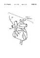
- FIG. 1is a schematic showing a heart.
- FIG. 2illustrates a prior art method of locating an incision in an artery for performing an anastomosis.
- FIGS. 3, 4, 5A, 5B, and 6-9illustrate prior art means and methods of performing an anastomosis.
- FIG. 10illustrates the principle of the present invention in which an anastomosis includes a hemostatic medium located in such a manner that clots will form externally of the blood vessel.
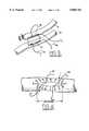
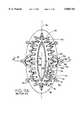
- FIG. 11is a side view of a cuff which is included in the means for performing an anastomosis according to the present invention.
- FIG. 11Ais a sectional view taken along section line A--A of FIG. 11.
- FIG. 12is an sectional view of the cuff taken along line B--B of FIG. 11A.
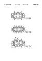
- FIGS. 13A-13Fshow alternative forms of a cuff.
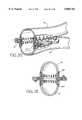
- FIG. 14is an exploded view showing a singe cuff form of the invention prior to joining a graft and an artery.
- FIG. 15is a cut away view showing the single cuff form after the graft has been joined to the artery.
- FIG. 16is an elevational cross sectional view of the single cuff form of the invention joining a graft to an artery.
- FIG. 17is a perspective view of an anastomosis formed using the single cuff form of the invention in a side-to-side configuration, those skilled in the art being able to understand what an end-to-side configuration will look like based on the teaching of the present disclosure.
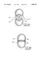
- FIG. 18Ashows a single cuff form of the invention just prior to drawing the ends of the two blood vessels together.
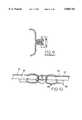
- FIG. 19is an exploded perspective view of one form of the invention in which two cuffs are used to join an artery with a graft.
- FIG. 20is a perspective view of a section of the joined artery and graft using two cuffs.
- FIG. 21is an elevational cross sectional view of the two cuff form of the invention in situ.
- FIG. 22is a perspective view of the two cuff form of the invention in an anastomosis which joins a graft to an artery in an end-to-side configuration.
- FIG. 23is a perspective view of the two cuff form of the invention in an anastomosis which joins a graft to an artery in a side-to-side configuration, with the graft being tied off by a suture.
- FIG. 24is an elevational view of another form of the two cuff form of the invention showing how the two cuffs are held together whereby the graft and the artery are pulled together in healing abutment.
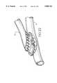
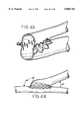
- FIG. 25Ais an exploded perspective view of a tool used in performing the anastomosis according to the present invention, with a cuff in place.
- FIG. 26is a perspective view indicating the tool in use in placing a cuff on an artery.
- FIG. 27is an elevational view of a tool in place in an artery just prior to setting a cuff on the artery.
- FIG. 28is an elevational view of a tool in place after a cuff has been set onto an artery and just prior to removing an anvil of the tool from the artery.
- FIG. 29is an elevational view of a tool with an anvil in place in a graft for placement of a single cuff form of the invention.
- FIG. 30shows a graft vessel prepared to receive a cuff.
- FIG. 31shows a tool holding a cuff prior to placing the cuff on the graft vessel shown in FIG. 30.
- FIG. 32shows a tool used to cinch a cuff to a graft vessel that has been located in a cuff.
- FIG. 33shows a graft vessel located in a cuff prior to being cinched to that cuff by the tool shown in FIG. 32.
- FIG. 34shows the tool just prior to setting the means for attaching the cuff to the graft vessel.
- FIG. 35shows an alternative form of a tool for applying a cuff to a graft vessel.
- FIGS. 36A-36Dshow the steps used in applying a cuff to a graft vessel using the tool shown in FIG. 35.
- FIG. 37shows a tool applying the means for holding the cuff to the vessel in which the means is such that the vessel will not be damaged.
- FIG. 38shows a tool used to join two cuffs together.
- FIG. 39shows the tool used to join two cuffs together docked to one cuff and prior to joining that cuff to another cuff.
- FIG. 40shows the tool docked to one cuff and joining that cuff to another cuff.
- FIG. 41is a flow chart for the method of performing an anastomosis for a single cuff form of the invention with the vessels being joined in a side-to-side configuration.
- FIG. 42Ais a flow chart for the method of performing an anastomosis for a double cuff form of the invention with the vessels being joined in a side-to-side configuration.
- FIG. 42Bis a flow chart for the method of performing an anastomosis for a double cuff form of the invention with the vessels being joined in an end-to-side configuration.
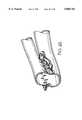
- FIG. 43shows a single cuff form of the invention which has omitted the hemostatic medium.
- FIG. 44shows the continuously varying nature of the junction angle.
- FIG. 45shows the double cuff form of the invention which has omitted the hemostatic medium.
- FIG. 46shows how the means and method of the present invention can be applied to a multiple graft technique.
- FIGS. 1 and 2indicate the locating and performing of an arteriotomy.
- locating the position of an anastomosisis extremely important and extremely delicate. The location must be selected with extreme accuracy and precision. This is especially so since the blood vessels are often extremely small.
- FIGS. 1 and 2where the location of a restriction is indicated as R and an arteriotomy is indicated at I in FIG. 2.
- the arteriotomymust be made in a proper location with respect to the restriction R or the surgery will not be as effective as it could be.
- an anastomosismust be performed accurately and effectively to be successful.
- the present inventiondiscloses and teaches a means and a method of performing such an anastomosis.
- FIG. 3Shown in FIG. 3 is an anastomosis involving a artery 10 and a graft 12 that is performed according to the prior art. That is, an incision 14 is defined in artery 10 and a corresponding incision 16 is defined in graft 12. Sutures 18 and 20 are set near the ends (heel and toe) of the incisions. Additional sutures are set as indicated in FIG. 4 by reference numerals 1-9 and 1'-9'. Sutures are indicated at 22 and 24. Once the sutures are set, the graft and the artery are drawn together as indicated in FIGS. 5A and 5B.
- the inside edges of the graft and the artery adjacent to the incisionsare placed into abutting contact with each other to promote proper healing.
- the inside edge of the graft vesselis indicated in FIG. 5A at 26 and the inside edge of the artery is indicated at 26' in that same figure.
- the ideal situationhas inside edge 26 in abutting contact with inside edge 26' of the artery.
- hand suturingis susceptible to errors and imprecision, especially when the graft and/or artery is extremely small. In the case of a minimally invasive surgery, this precise placement may be nearly impossible.
- FIGS. 6-9where ring 30 is placed between two end-to-end vessels in FIG. 6 and rings 30' and 30" are used with two end-to-side joined vessels in FIG. 7.
- the ringsserve as the means for holding the joined vessels together.
- the ringshave several drawbacks, including evaginating the vessels, restricting the vessels so growth due to higher blood flow is restricted, and stretching the vessel which causes flattening of the vessel as indicated at portion 32 in FIG. 8.
- the use of ringssuggests that an anastomosis is being viewed as a plumbing connection between two conduits. As was also discussed above, this is simply not the case with actual blood vessels. As discussed above, if too much clamping is applied to the vessels, necrosis may occur. Unhealthy tissue may cause scarring and in fact may fail to heal. This situation is illustrated in FIG. 9.
- the present inventionis intended to permit the performance of an anastomosis in a minimally invasive manner yet to perform the procedure in an accurate manner and in a manner that promotes proper healing.
- the most effective healingwill occur when the hemostatic medium is located on the outside of the blood vessel so any clots will form on the outside of the vessel. This basic concept is illustrated in FIG.
- FIG. 10which shows an anastomotic device AD comprising a hemostatic medium HM having a stent which includes means FM for fastening the stent to the vessel and which is located on the outside of one blood vessel B1 which is to be joined to another blood vessel B2 and for bringing vessel walls, and the endothelial lining E1, of the one blood vessel into intimate approximation with other vessel walls, represented by endothelial lining E2, of the other blood vessel whereby fibrin clot FC is formed in the proper location to effect a successful procedure. Still further, excessive clamping is avoided in the present invention by obviating the need for clamps, such as are commonly used in prior art techniques.
- FIGS. 11-18BThere are two forms of the invention, a single cuff form (see FIGS. 11-18B) and a single cuff form (see FIGS. 19-24).
- this mounting elementwill be referred to as a cuff.
- no limitationis intended by this shorthand reference.
- the single cuff form of the inventionhas the cuff mounted on the artery and the graft blood vessel with the vessels being brought into contact with the vessel attaching elements of the cuff to attach the two vessels together. It is here noted that for the sake of brevity, the discussion will be directed to blood vessels; however, those skilled in the art will be able to understand that the teaching can be applied to vessels of any sort that occur in a patient. Accordingly, no limitation is intended by the reference to a "blood" vessel.
- the double cuff form of the inventionhas one cuff attached to the graft and a separate cuff attached to the artery. These cuffs are then attached to each other to effect the connection.
- the single cuff form of the inventionhas a single cuff attached to both the graft blood vessel and to the artery, with the single cuff attaching the two blood vessels together to effect the connection.
- the double cuff form of the inventionhas each cuff individually mounted on a blood vessel by an instrument, and the two cuffed vessels brought together with the cuffs then coupled together.
- FIGS. 11, 11A and 12Shown in FIGS. 11, 11A and 12 is a single cuff 40 embodying the present invention.
- the cuffis applied to a blood vessel and will couple that vessel to another vessel or to another cuff.
- the cuffcan be applied to a blood vessel by an instrument while blood still flows through the vessel by using a stabilizing cuff application tool with a flow-through anvil. This enables anastomotic surgery to be performed without stopping the heart so the procedure can be carried out in a minimally invasive manner.
- the cuffalso permits proper shaping of the junction without mishandling the blood vessels and places the two vessels in an orientation that promotes efficient healing.
- cuff 40includes an oval shaped flexible body 42 having a long axis 44 and a short axis 46 with an oval shaped opening 48 defined therein by the cuff body central section 49.
- the preferred form of body 42is a woven fabric suitable for use in surgery.
- a stiffening framework 50 of a retention means, such as a malleable material,is integrated into body 42 for retaining the cuff in a selected shape on a blood vessel.
- the preferred form of the retention meansis sinuous and includes a plurality of malleable sections, such as section 52. In the present context, this element will be referred to as a retention means.
- this elementcan also be referred to as a "stent” or a “stiffening band.”
- One form of the materialis a wire that is suitable for use in the surgical environment associated with this invention.
- the retention meanshas little material memory in that once deformed from one shape into another, it will not move back into the first shape from the second.
- a second potential form for the retainer meansis shaped from flat stock which is processed using precise methods such as wire EDM or photo etching. Shaping the cuff is therefore efficiently carried out by deforming it into the desired shape after it is mounted on a blood vessel.
- the retention meanswill maintain the cuff in the shaped condition. Sections of the stiffening framework may be separate from other sections, such as quartered sections or the like.
- Each malleable sectionhas an apex, such as apex 54, with a cuff retaining pin, such as pin 56, thereon.
- Cuff retaining pins 56attach the stiffening framework 50 to the cuff
- anchor means 58attach base 60 of each section 52 to body 42 to securely anchor the stiffening framework to body 42.
- many cuff pinsmay be used to secure the cuff frame to the cuff.
- Tissue retention pins 62are attached at a proximal end 64 thereof to the body 42 and have a distal end 66 which engages a blood vessel to anchor the cuff to that blood vessel in the manner of a surgical staple.
- the instrument discussed belowis used to force the retention pin into the blood vessel tissue to anchor the cuff to the blood vessel.
- Means for shaping the cuff once it is anchored on the blood vesselincludes docking extensions, such as docking extensions 70 having a proximal end 72 unitary with a base of a malleable section of the stiffening framework and a distal end 74 spaced from the outer perimeter 76 of the cuff body 42.
- An eyelet 78is located on distal end 74 having a central hole 80 defined therein to engage a corresponding element on the instrument used to place the cuff.
- the means for shaping the cuffalso includes a plurality of second docking extensions 82 having proximal ends 84 integral with alternate apexes of the stiffening framework 50 and a distal end 86 having an eyelet 88 with a central hole 90 for releasable connection to a corresponding element on the instrument used to place the cuff.
- the docking extensionsare engaged with the instrument, and once the cuff is anchored to a blood vessel, the instrument can be manipulated by the surgeon to shape opening 48 to the desired size and shape. Once the desired size and shape have been established, the cuff and framework is released from the instrument.
- the cuffhas an hour glass shape in elevation, with body 42 having a first end section 92 and a second end section 94 of roughly the same outer dimension, with central section 49 having an outer dimension of less than those outer dimensions to define a waist section.
- body 42having a first end section 92 and a second end section 94 of roughly the same outer dimension, with central section 49 having an outer dimension of less than those outer dimensions to define a waist section.
- FIGS. 13A-13FOther forms of the single cuff are illustrated in FIGS. 13A-13F.
- FIGS. 14-18BUse of the single cuff form of the invention is illustrated in FIGS. 14-18B.
- the tool for effecting the placement of the cuff and the coupling of the two vesselswill be discussed below in connection with FIGS. 25 et seq. For present purposes, the results will be shown and discussed.
- FIG. 14After the graft vessel G and the artery A have been prepared, the cuff is placed on the artery A. The graft vessel is then moved into proximity of the cuff as shown in FIG. 14 and joined to the cuff as shown in FIGS. 15 and 16.
- the single cuff form of the inventioncan include a means, such as bridge means 110 shown in FIGS. 18A and 18B to draw the adjacent blood vessel inside edges 26 and 26' together into abutting contact from the spaced positioning of these two edges shown in FIG. 18A to the abutting contact shown in FIG. 18B.
- Bridge means 110includes a malleable wire 112 or extensions 70, 82, etc.
- bridge wire 112when bridge wire 112 is deformed from the FIG. 18A configuration to the FIG. 18B configuration, it will retain the FIG. 18B configuration thereby placing the inside edges 26 and 26' in abutting contact with each other. Deformation of wire 112 can be effected with a proper tool.
- the bridgecan also be formed from shaping pins resistance welded together.
- junction anglenoted by JA in FIG. 18B.
- This anglevaries continuously with respect to a linear reference, such as the longitudinal centerline of the vessels at the junction, as a unit vector associated with the angle follows around the periphery at the anastomotic junction.
- the means and method of the present inventionpermits this variation in angle.
- This variation in junction angleeffects a properly shaped anastomosis for dissimilarly sized vessels.
- This anglewill also vary at the heel and the toe depending on the appropriate angle of the graft vessel, as shown in FIG. 44 at JA', JA" respectively.
- FIG. 17a single cuff side-to-side anastomosis is shown in FIG. 17.
- FIGS. 19-24The double cuff form of the invention is illustrated in FIGS. 19-24.
- one cuff 40'is attached to a graft blood vessel G
- a second cuff 40"is attached to the artery A.
- FIG. 19there is a spacing between the fastening means attaching the cuff to the vessel and the edge of the artery. This spacing is selected so the loose edge of the vessel can still be controlled, but the fastening means is not located too close to the edge of the vessel. Bringing the cuffs together in this manner does not mishandle the blood vessels and promotes efficient healing of the junction.
- a spacing of 1/2 mm to 1 mmis shown in FIG. 19. However, this spacing is disclosed for the sake of completeness and is not to be taken as limiting.
- Means for joining one cuff to the other in the double cuff form of the inventionincludes one unit 98 fixed to the graft (cuff) blood vessel G and one unit 99 fixed to the artery (cuff) A.
- a female element 100is fixed to cuff 40' and a corresponding male element 102 is fixed to cuff 40".
- Female element 100includes an eyelet 104 that has an opening sized and shaped to snugly receive male element 106 mounted on element 102 to establish a friction fit between elements 100 and 102 that securely couples the two cuffs together.
- the preferred form of the cuff joining meansincludes four male elements and four female elements on each base 98 and 99, each being located on opposite sides of the cuffs as is shown in FIGS. 22 and 23. Each cuff has two male elements and two female elements with the male elements on each base whereby a secure attachment is effected.
- the double cuff form of the inventionuses two cuffs, such as 40' and 40", to attach two blood vessels together, whereas, the single cuff form of the invention uses a single cuff 40'" to attach two blood vessels together.
- the double cuff form of the inventionhas two similar cuffs attached together by a coupling means.
- the single cuff form of the inventionhas a single cuff with the two ends thereof identical each having a stiffening framework therein and each having tissue retention pins 62'" therein.
- a single body unitary 42'"forms the cuff 40'".
- the double cuff form of the inventionis applied as indicated in FIGS. 19-23.
- a toolwhich will be discussed below in connection with FIGS. 24 et seq, is used to place a cuff on the graft, and then a second cuff on the artery.
- the vesselsare then oriented adjacent to each other as indicated in FIG. 19, and then brought together so the two cuffs are coupled as indicated in FIG. 20.
- the cuffsare then coupled together as indicated in FIG. 21 to form an end-to-side anastomosis as indicated in FIG. 22 or to form a side-to-side anastomosis as shown in FIG. 23.
- the two cuffsare coupled together by a suitable fastener, such as the above-discussed male/female coupling shown in FIG. 21.
- FIG. 24An alternative form of the cuff joining means for the double cuff form of the invention is shown in FIG. 24.
- This form of the cuff joining meansincludes rivets or staples 114 in place of the male and female elements discussed above.
- the rivets or staplesare placed in bases 98 and 99 and hold the bases together in the manner discussed above for the male and female elements 104 and 106.
- the anastomosis technique of the present inventionis intended to be performed in a minimally invasive manner. Therefore, the cuffs discussed above must be placed on blood vessels that are located inside a patient, with the artery carrying blood. As was also discussed above, the anastomosis technique of the present invention may involve extremely small blood vessels. Accordingly, the instrument used to effect the anastomosis must be very accurate and precise, yet will not mishandle the blood vessels during performance of the technique.
- the instrumentwill place a cuff on the artery while permitting blood to flow through that artery, and then will place a corresponding cuff on the graft blood vessel, or will attach the graft blood vessel to the single cuff mounted on the artery in the single cuff form of the invention.
- the instrumentwill then be used to shape the cuffs so the junction is the most efficient and will permit proper healing. All of this must be carried out in a minimally invasive manner.
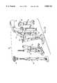
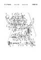
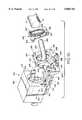
- Instrument 120broadly comprises a handle frame 122 having a handle 124 that is grasped by a surgeon during operation of the instrument, and a finger frame 126 having a finger grip 128 which is operated by the surgeon, two driver elements 130 and 132 pivotally attached to the handle frame, a graft anvil 134 and an artery anvil 136.
- handle frame 122includes a U-shaped section having legs 140 and 142 attached at one end to handle 124 and which are spaced apart to define a channel 144 therebetween.
- Each leghas an inside surface 146 with L-shaped anvil alignment slots 148 and 150 defined in the legs to have short legs 152 that intersect the channel and long legs 154 defined to be parallel to the channel.
- L-shaped anvil alignment slots 148 and 150defined in the legs to have short legs 152 that intersect the channel and long legs 154 defined to be parallel to the channel.
- the handle framefurther includes two ears 156 and 158.
- the earsinclude two spaced apart plates 160 and 162 with bores 164 and 166 defined in each plate to be centrally aligned with each other for a purpose that will be understood from the following discussion.
- the handle framefurther includes two rails, such as rail 170, on the outer edges of the legs 140 and 142.
- An undercut region 174is defined in the proximal end of the handle frame with a top shoulder 176 defined therein at the top entrance to channel 144.
- Shoulder 176is U-shaped and has a channel 178 defined between leg 180 corresponding to leg 140 and leg 182 corresponding to leg 142.
- Finger frame 122includes a U-shaped base 184 having two legs 186 each connected to a center section 190 and defining a channel 192 therebetween.
- a slot 194is formed at the intersection of each leg and the center section, with slots 194 being sized and located to slidably receive rails 170. Sliding engagement between the rails and the slots permits the finger frame to move with respect to the handle frame longitudinally of the channel 190 as is indicated by the double-headed arrow 196, with handle frame 122 moving in direction 198 with respect to finger frame 126 to open the instrument anvils and moving in direction 200 with respect to the finger frame to close the instrument anvils as will be discussed below.
- Each leg 186 of the finger frame 126further includes an ear, such as ear 202 on a distal end thereof to which a guide pin, such as guide pin 204, is fixed to extend past the handle frame leg adjacent thereto.
- Instrument 120further includes two pivot pins 206 and 208 accommodated in the aligned bores 164 and 166.
- Each of the driver arms 130 and 132has a pivot pin receiving hole 210 and 212 respectively defined in the proximal end of arms 214 and 216 respectively.
- a crescent-shaped driver element 218 and 220is located on the distal end of each arm 214 and 216 respectively with a cam slot 222 and 226 being defined in the arms 214 and 216 respectively.
- the armsare pivotally attached to the handle frame by the pins 206 and 208 to move in directions 226 and 228 as indicated by double-headed arrow 230 when finger handle 126 moves directions 198 and 200 respectively to open and close the driver heads 218 and 220.
- Slots 222 and 226slidably receive guide pins 204 to effect this opening and closing movement. Since the driver arms are fixed at an angle to handle frame 122 by pivot pins 206 and 208 and guide pins 204 move longitudinally with respect to the handle frame and slidably engage cam slots 222 and 226, longitudinal movement of the finger frame with respect to the handle frame will cause the above-mentioned pivotal movement of the anvil arms.
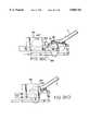
- the opening and closing of the driver armsis illustrated in FIGS. 27 (closing) and 28 (opening).
- Each driver head, 218, 220has a V-shaped cuff-engaging edge, such as edge 232 which is sized and shaped to engage the waist section 49 of a cuff.
- Each edge 232also has two surfaces 234 that diverge away from each other from the edge 232 to engage surfaces 236 and 238 (see FIG. 12) respectively of the cuff sections 92 and 94. Engagement of the surfaces 234 and 236, 238 along with a movement of the anvils 136 and 139 forces the tissue fasteners 62 into the tissue of the blood vessel while shaping the cuff to the blood vessel.
- instrument 120includes artery anvil 136 and graft anvil 134 which are removably fixable to the handle frame.
- Graft anvil 134includes a body 240 having a threaded portion 242 on a proximal end thereof, a graft anvil head 244 on a distal end thereof and alignment pins 246 between the two ends thereof.
- a fastening knob 247is also included with instrument 120, and is internally threaded to threadably engage threaded portion 242.
- Knob 247is accommodated in undercut area 174 and threaded portion 242 is extends through channel 178 to be engaged by the threaded portion of the fastener 247.
- Longitudinal movement of the graft anvil in directions 260 and 262is effected by threading the knob 247 on the threaded portion 242.
- Threaded movement in one directionmoves the graft anvil in direction 262 and threaded movement in the opposite direction moves the graft anvil in direction 260 whereby the location of the graft anvil head 244 with respect to the driver elements 218, 220 can be adjusted and set.
- the purpose of this movementwill be understood from the discussion in this disclosure.
- Body 240includes a first portion 248 and a second portion 250 that is angled with respect to the first portion 248.
- Graft anvil head 244has a proximal end thereof fixed to portion 250 to extend transverse to longitudinal centerline 252 of the body 240.
- the length of body 240 as measured between its proximal and distal endsis greater than the length of the handle frame as measured along its longitudinal centerline 252 between the shoulder 176 and distal end 256 whereby graft anvil head 244 is spaced from distal end 256 when the graft anvil 134 is mounted on the handle frame.
- Arm 248is also long enough so that graft anvil head 244 is also spaced from driver heads 218 and 220 when the graft anvil is in place on the handle frame.
- Alignment pins 246are received through anvil slots 148 and 150 and are slidably accommodated in slots 154 so the graft anvil is securely and movably affixed to the handle frame.
- Artery anvil 136includes a body 270 having a threaded portion 272 on a proximal end thereof and an artery anvil head 274 on a distal end thereof. Alignment pins 276 are located on the body to be received through alignment slots 152 and slidably accommodated in slots 154 on the handle frame.
- threaded portion 272extends through channel 178 and is threadably received by knob 247 to attach the artery anvil to the handle frame and to move that artery anvil in directions 260 and 262 with respect to the handle frame as was discussed above with regard to the graft anvil whereby the location of the artery anvil head 274 with respect to the driver heads 218, 220 can be set.
- the artery anvil head 274is located beneath the driver heads so that the head can be inserted into an artery and a cuff being supported by the driver heads will be located outside that artery.
- the knob 247is operated to move the anvil head 274 toward the driver heads 218, 220 until the cuff supported in the heads 218, 220 engage the outside of the artery.
- the tissue retention pinscan then be set.
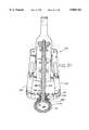
- Artery anvil head 274includes a bullet shaped body 280 having two ends 282 and 284 with a bypass channel 286 defined longitudinally therethrough from one end 282 to the other end 284. This channel permits blood flow through the anvil head maintaining perfusion while the cuff is being attached.
- a fastener turning section 288is defined in top surface 290 of the head 274 adjacent to the intersection of the head and the body 270 and in a location to receive ends 66 of the tissue fastening pins when they are forced through the blood vessel wall.
- the fastener turning sectionis concave so the pin is turned as it engages and follows the anvil head surface adjacent to the turning section. This rotates the fastener end so the fastener is gradually bent from the FIG.
- tissue fasteneris forced to follow this turning section by engagement of the driver head surface against the cuff and against the fastener body 62 as the heads 218, 220 are moved into engagement with the cuff by operation of the finger frame 122 and as the artery anvil is moved in direction 260 by operation of the knob 247 on threaded portion 272.
- Driver heads 218, 220include docking pins 294 which releasably engage holes 80 and 90 of the docking pins 70 and 82 on the cuff to control the shape of the cuff.
- the friction fit between pins 294 and the pins 70 and 82is great enough to permit the cuff to be pulled and shaped by movement of the driver heads, but low enough so the pins 294 can be pulled out of the docking elements without pulling the cuff off of the blood vessel.
- pins 294could be retracted through a flexible shaft connected up to the handle. Pulling the driver heads outwardly in direction 226 will enlarge the junction and will change its shape from oblong toward circular. Therefore, a surgeon can shape the junction in the manner that is most efficient to healing and to defining an effective anastomosis.
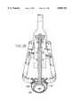
- FIG. 26An assembled instrument is shown in FIG. 26 with an artery anvil being inserted through an incision I in an artery A and a cuff 40 on the driver elements.
- the artery anvil headis button holed into the artery via the incision.
- the anvil headis actually larger than the incision in the artery but can be angled through the incision into position as shown in FIG. 26.
- the knob 247is operated to draw the anvil head and vessel surface at the incision up toward heads 218, 220. This action also isolates the working area from motion associated with the beating heart. As indicated in FIG.
- driver heads 218, 220are operated to force the edges 232 against the waist 49 and against the surfaces 236 and 238, and the knob 247 is further operated to draw the anvil and the cuff together. Further operation of the knob 247 forces the tissue fasteners through the blood vessel tissue, into turning section 288 and around on themselves in the manner of a staple whereby the cuff is fixed to the blood vessel. During this operation, blood flows through the artery via channel 286.
- the driving heads 218, 220are opened as shown in FIG. 28 so the anvil head 280 can be removed from the artery. Since the cuff is connected to the driver heads, opening the driver heads will enlarge the incision thereby permitting the artery anvil to be removed.
- the graft vesselis prepared in a similar manner.
- the graft anvilis inserted into the graft blood vessel via the end of that blood vessel and is tied to the graft anvil head 244 with a garroting suture.
- the graft anvil 134is attached to handle frame 122.
- the instrumentis operated to attach a cuff to the graft blood vessel in a manner similar to that just described for attaching a cuff to the artery.
- the graftis prepared first because the surgeon has more time to work on the graft than on the artery.
- the graft anvilallows the surgeon to prepare the graft on the anvil first and then attach the anvil to the instrument at a later time when it is convenient to do so.
- the instrumentis then maneuvered so the graft blood vessel is adjacent to the cuff mounted on the artery.
- the knob 247is then operated to force the graft blood vessel into contact with the cuff portion that is not attached to the artery to attach the graft vessel to the artery attached cuff.
- the graft anvil headhas a fastener turning section 296 which operates to turn the fasteners in that section of the cuff in a manner identical to the above-described turning of the fasteners in the artery. This is illustrated in FIG. 29 for a single cuff embodiment.
- Turning section 296is used to turn the tissue retention pins to either attach a single cuff to the blood vessel or to attach a separate cuff to the blood vessel.
- the driver heads 218, 220are manipulated to enlarge the graft incision to permit the graft anvil head to be withdrawn from the graft vessel via the end of that vessel.
- the driver headscan then be further manipulated to size and shape the junction, and then manipulated to remove the docking pins 70 and 82 from the anvil pins 294 to release the cuff or cuffs from the instrument.
- the garrot sutureis cut and the graft anvil is removed from the graft.
- the graft blood vesselis then tied off and the anastomosis is complete.
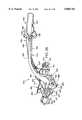
- FIGS. 30-34Instrument for mounting a cuff on the graft artery Shown in FIGS. 30-34 is one form of an instrument used to mount a cuff on a graft artery. An alternative form of the instrument is shown in FIGS. 35-37.
- a graft Gis prepared by defining an incision IG therein.
- the grafthas been removed and is being prepared and cuffed outside of the patient.
- An instrument 300is shown in FIG. 31 and includes tongs 302 and 304 having cuff-engaging ends 302' and 304' respectively, and handles 302" and 304" respectively which are gripped by the surgeon.
- a pivot 306is located at the intersection of the tongs.
- Each of the tongshas a cutout portion which conforms to one-half of the shape of a cuff whereby a cuff will be securely held in the tongs as indicated in FIG. 31.
- Elements 106'"are located on the tongs to engage the female elements on the cuff to hold the cuff in position on the tongs.
- each tonghas a cutout section 310 for engaging anvil 312 shown in FIG. 32.
- Anvil 312includes a central section 314 having an opening defined in a top section 316 thereof.
- a section 318includes two side sections 324 and 322, each of which has a cutout, such as cutout 326 in side 322, defined therein.
- Anvil 312further includes a threaded element 328 extending through the opening defined through top section 316 and is pivotally attached to section 318 at 329. Threaded element 328 is threadably received through a threaded opening 326' defined through section 336.
- a knob 330is unitary with the threaded element 328. Rotation of the knob moves top section 318 relative to arms 334 as indicated by double-headed arrow 332. Arms, such as arm 334 have top section 336 engaging the threaded element 328. Movement of the threaded element causes the hook sections 338 to move into and out of the cutouts.
- graft Gis drawn upwardly through the cuff mounted on instrument 300 to located edge GE above the cuff, and above the fasteners 66 of the cuff. Then, as indicated by arrow 340, anvil 312 is moved to orient hooks 338 in cutouts 310. This condition is shown in FIG. 34.
- Side sections 322 and 324are unitary, and each includes a fastener turning area 343 and 345 located to engage fastener 66 when the anvil is operated.
- FIGS. 35-37An alternative form of an instrument used to mount a cuff on a graft is shown in FIGS. 35-37.
- the graftis prepared in the manner discussed above.
- End cuff attaching tool 350includes a housing 352 having a forming cavity 354 defined therein to extend from end wall 356 adjacent to edge forming elements 358 and 360.
- Housing 352is slidably mounted on plate 362 by a track 363 to be moved by hand pressure in directions 363' and 363".
- Housing 364is mounted on plate 362 and slidably receives a pushrod 366.
- Pushrod 366has a link 368 attached at one end thereof by a pivot pin 370. Pushrod 366 can be operated by hand to move in directions 372 and 374 as indicated by double-headed arrow 376.
- a tilt table 380is pivotally attached to the plate 362 by pivot pins, such as pin 382, and is pivotally attached to the link 368 by pin 384.
- pivot pinssuch as pin 382
- pin 384pivotally attached to the link 368 by pin 384.
- movement of the pushrod in direction 374tilts the table in direction 386 about pin 382, and vice versa for pushrod movement in direction 372.
- the tablemoves from the position shown in FIG. 35A to the position shown in FIG. 35C under the influence of this pushrod movement.
- a vessel receiving element 390is mounted on one end of the plate 362 to extend upwardly and outwardly therefrom at an angle as shown in FIG. 35.
- Table 380includes a cutout section 392 which receives a cuff with cuff toe 394 on top and cuff heel 396 on the bottom.
- Table 380includes alignment pins 398 that are received in alignment holes 400 on the cuff, and alignment holes 402 that receive alignment pins 404 on the cuff to releasably secure the cuff to the table.
- shaft 390will extend through the cuff-receiving section 392 and through the cuff mounted on the table.
- Graft Gis placed over the shaft to extend through the cuff with end 406 attached to hooks 408 on the table to temporarily mount the graft to the instrument plate 362.
- Operation of the pushrodtilts the table in direction 386 to bring the cuff down on top of the graft as can be understood from FIGS. 36A, 36B and 36C.
- the housing 352is moved toward the end of the table in direction 363" as shown in FIGS. 36C and 36D.
- the cuff and graftare guided into cavity 354 and the front end of the cuff and graft engage the end of the cavity as indicated in FIGS. 36D and 37.
- the shaft 390includes fastener turning areas, such as area 410 and the turning movement of the table forces cuff fasteners through the graft and into engagement with the shaft at the turning areas. Further turning movement of the table turns the fasteners to couple the cuff to the graft. Movement of the housing 352 in direction 363" engages J-shaped fastener 66' with the housing and forces that fastener through the graft and into turning area 410. Further movement of the housing turns the fastener to couple the cuff to the graft.
- the cuffis coupled to the graft and the housing can be moved in direction 363' and, table 380 moved opposite to direction 386.
- the cuffed-graftcan then be removed from the shaft 390.
- the J-shape of fasteners 66'prevents the graft vessel from becoming damaged from otherwise protruding pins from the cuff as the tilt-table is being rotated. The variation in shape of the fasteners thus protects the graft vessel.
- the graft vesselcan be set aside until the artery is cuffed.
- Instrument for coupling one cuff to anotherShown in FIGS. 38-40 is an instrument that can be used to couple one cuff to another in the double-cuff form of the invention.
- instrument 450is releasably attached to a vessel-mounted cuff, and is then operated to attach that cuff to another vessel-mounted cuff.
- One cuffcan be attached to an artery using the instrument shown in FIG. 25 (using elements 130, 132 and 136) while a cuff can be attached to a graft using the instrument shown in either FIG. 31 or FIG. 35 in an end-to-side anastomosis, or using the instrument shown in FIG. 25 twice (using elements 130, 132 and 136 to attach a cuff to an artery and using element 134 to attach a cuff to a graft) in a side-to-side anastomosis.
- Instrument 450includes a handle 452 having a hand-grip 454 on one end thereof.
- a trigger housing 456is mounted adjacent to the hand grip.
- An anchor element 458is also mounted on the handle adjacent to the hand grip.
- a cuff engaging section 460is mounted on the other end of the handle and includes a base 462 having a forward end 464 and an aft end 466.
- Cuff engaging C-shaped hooks 468are pivotally mounted on the base section by pivot bars, such as bar 470 extending through the hooks so the hooks pivot in directions 472 and 474.
- Clamping hooks 476 and 478are also pivotally mounted on the base section by bars 470 to move in the directions 472 and 474.
- Hooks 468are spring biased in direction 474 by springs, such as spring 480 and hooks 476 and 478 are fixed to bar 470 for rotation therewith.
- Hooks 476include cutout portions, such as portion 482. It is noted that a hook 478 is not shown in FIG. 38 but is located on the base diametrically opposite to hook 478. Hooks 468 clamp instrument 450 to the cuff, and hooks 476 and 478 force the male fastening elements such as element 106 of one cuff through female elements, such as element 104, of the other cuff. For this reason, hooks 476 include a cutout section to accommodate the male element, whereas hooks 478 do not include a cutout section as these hooks engage the female elements.
- hooks 468are operated by mechanism 490 which includes a tether 492 attached at one end thereof to element 458 and at the other end thereof ears 494 on each hook 468.
- Tether 492extends through guide 496 which is located between the ears 494. Therefore, movement of element 458 in direction 498 draws ears 494 together in directions 500' and 500" against the bias of springs 480.
- the springstend to move the hooks into cuff engaging positions, such as shown in FIG. 39, and the tether is operated to release tool 450 from the cuff.
- the tool 450is shown attached to a vessel mounted cuff in FIG. 39.
- Hooks 476 and 478are operated by a system 504 which includes a tether 506 attached at one end thereof to the trigger housing 456 and at the other end thereof to levers 506.
- the tetherextends through guides 508.
- Levers 506are pivotally mounted on the base section by pins 510 to move in direction 512 when the trigger housing is moved in direction 514.
- the pivot pins 510are fixed to rod 470 to rotate that rod in direction 512 with the levers.
- Hooks 476 and 478are fixed to the rod 470 for rotation therewith, and rotation of the levers in direction 512 rotates the rod 470 in direction 516. Rotation of the hooks 476 and 478 in direction 516 moves those hooks from the FIG. 38 position to the cuff engaging position shown in FIG. 40.
- Rod 470is also spring biased by a torsion spring, so when the trigger housing is released, that rod will rotate to release hooks 476 and 478 back into the FIG. 38 position.
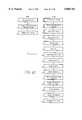
- FIGS. 41, 42A and 42Brepresent the method of using the above-described instrument in performing an anastomosis according to the teaching of the present invention.
- the location of the anastomosisis determined.
- the graftis pulled onto the graft anvil.
- the graftis garroted to the graft anvil.
- the graft and graft anvilare set aside.
- Button-hole arteryanvil into interior lumen of the artery.
- FIG. 42AThe double cuff technique is shown in FIG. 42A for a side-to-side anastomosis and in FIG. 42B for an end-to-side anastomosis.
- hemostatic mediumis shown in the preferred embodiments, there may be certain uses, such as mentioned above, of the device that will not require the hemostatic medium.
- the joining at lumens like fallopian tubesis one example. It is therefore contemplated that this disclosure will cover an anastomosis means and method which omits the hemostatic medium.
- FIG. 43One example of this hemostatic medium-less anastomosis is shown in FIG. 43 in which the tissue pins are staggered in a manner that allows the approximation of the tissue in a sinuous junction line. This will mimic the type of approximation that sutures provide by interweaving from one side to the other.
- the sinuous junction SJis shown in FIG. 43 as tissue pins attached to an external malleable stent S. Tissue is shown as T.
- FIG. 43shows a single cuff design with only one bridge being shown for the sake of clarity of disclosure, it being understood that other bridges, as discussed above, are also included in the FIG. 43 embodiment.
- a double cuff designis shown in FIG. 45, with only one coupling element being shown.
- a proximal graft attachment to aortic supplyan anastomosis of other luminal structures such as, but not limited to, Fallopian tubes urethra, ureter, bile ducts, etc. can also be performed using the means and method disclosed herein.
- FIG. 46shows the use of the present means and method as applied to multiple grafts.
- an existing blood supply conduitsuch as the IMA
- an artificial supply vesselmust be grafted.
- another vesselsuch as the saphenous vein is harvested from the patient's leg.
- the graftmust be attached to a supply. This is usually the aorta AA.
- a proximal anastomosis Pis performed using the techniques discussed above to attach the new supply conduit to the aorta. The means and method discussed above is used to perform this procedure.
Landscapes
- Health & Medical Sciences (AREA)
- Life Sciences & Earth Sciences (AREA)
- Surgery (AREA)
- Heart & Thoracic Surgery (AREA)
- Engineering & Computer Science (AREA)
- Biomedical Technology (AREA)
- Nuclear Medicine, Radiotherapy & Molecular Imaging (AREA)
- Medical Informatics (AREA)
- Molecular Biology (AREA)
- Animal Behavior & Ethology (AREA)
- General Health & Medical Sciences (AREA)
- Public Health (AREA)
- Veterinary Medicine (AREA)
- Surgical Instruments (AREA)
Abstract
Description
Claims (40)
Priority Applications (12)
| Application Number | Priority Date | Filing Date | Title |
|---|---|---|---|
| US08/714,615US5868763A (en) | 1996-09-16 | 1996-09-16 | Means and methods for performing an anastomosis |
| US09/200,796US6254617B1 (en) | 1996-09-16 | 1998-11-27 | Means and method for performing an anastomosis |
| US09/220,395US6241742B1 (en) | 1996-09-16 | 1998-12-24 | Means and method for performing an anastomosis |
| US09/325,457US6190397B1 (en) | 1996-09-16 | 1999-06-03 | Means and method for performing an anastomosis |
| US09/520,468US6488692B1 (en) | 1996-09-16 | 2000-03-07 | Access and cannulation device and method for rapidly placing same and for rapidly closing same in minimally invasive surgery |
| US09/641,284US6565581B1 (en) | 1996-09-16 | 2000-08-17 | Apparatus and method for performing an anastomosis |
| US09/654,605US6811555B1 (en) | 1996-09-16 | 2000-09-01 | Method and apparatus for performing anastomosis with eversion of tissue edges and joining of exposed intima of the everted tissue |
| US09/892,235US6652543B2 (en) | 1996-09-16 | 2001-06-26 | Means and method for performing an anastomosis |
| US10/384,250US6884251B2 (en) | 1996-09-16 | 2003-03-06 | Apparatus and method for performing an anastomosis |
| US10/683,797US20040097992A1 (en) | 1996-09-16 | 2003-10-10 | Means and method for performing an anastomosis |
| US10/855,604US7497865B2 (en) | 1996-09-16 | 2004-05-26 | Method and apparatus for performing anastomosis with eversion of tissue edges and joining of exposed intima of the everted tissue |
| US11/726,567US20070167964A1 (en) | 1996-09-16 | 2007-03-21 | Tubular anastomosis ring having alternating flexible and rigid sections |
Applications Claiming Priority (1)
| Application Number | Priority Date | Filing Date | Title |
|---|---|---|---|
| US08/714,615US5868763A (en) | 1996-09-16 | 1996-09-16 | Means and methods for performing an anastomosis |
Related Child Applications (2)
| Application Number | Title | Priority Date | Filing Date |
|---|---|---|---|
| US09/200,796DivisionUS6254617B1 (en) | 1996-09-16 | 1998-11-27 | Means and method for performing an anastomosis |
| US09/220,395ContinuationUS6241742B1 (en) | 1996-09-16 | 1998-12-24 | Means and method for performing an anastomosis |
Publications (1)
| Publication Number | Publication Date |
|---|---|
| US5868763Atrue US5868763A (en) | 1999-02-09 |
Family
ID=24870770
Family Applications (6)
| Application Number | Title | Priority Date | Filing Date |
|---|---|---|---|
| US08/714,615Expired - LifetimeUS5868763A (en) | 1996-09-16 | 1996-09-16 | Means and methods for performing an anastomosis |
| US09/200,796Expired - Fee RelatedUS6254617B1 (en) | 1996-09-16 | 1998-11-27 | Means and method for performing an anastomosis |
| US09/220,395Expired - Fee RelatedUS6241742B1 (en) | 1996-09-16 | 1998-12-24 | Means and method for performing an anastomosis |
| US09/325,457Expired - Fee RelatedUS6190397B1 (en) | 1996-09-16 | 1999-06-03 | Means and method for performing an anastomosis |
| US09/892,235Expired - Fee RelatedUS6652543B2 (en) | 1996-09-16 | 2001-06-26 | Means and method for performing an anastomosis |
| US10/683,797AbandonedUS20040097992A1 (en) | 1996-09-16 | 2003-10-10 | Means and method for performing an anastomosis |
Family Applications After (5)
| Application Number | Title | Priority Date | Filing Date |
|---|---|---|---|
| US09/200,796Expired - Fee RelatedUS6254617B1 (en) | 1996-09-16 | 1998-11-27 | Means and method for performing an anastomosis |
| US09/220,395Expired - Fee RelatedUS6241742B1 (en) | 1996-09-16 | 1998-12-24 | Means and method for performing an anastomosis |
| US09/325,457Expired - Fee RelatedUS6190397B1 (en) | 1996-09-16 | 1999-06-03 | Means and method for performing an anastomosis |
| US09/892,235Expired - Fee RelatedUS6652543B2 (en) | 1996-09-16 | 2001-06-26 | Means and method for performing an anastomosis |
| US10/683,797AbandonedUS20040097992A1 (en) | 1996-09-16 | 2003-10-10 | Means and method for performing an anastomosis |
Country Status (1)
| Country | Link |
|---|---|
| US (6) | US5868763A (en) |
Cited By (232)
| Publication number | Priority date | Publication date | Assignee | Title |
|---|---|---|---|---|
| WO2000076405A1 (en)* | 1999-06-10 | 2000-12-21 | Vascular Innovations, Inc. | Sutureless closure for connecting a bypass graft to a target vessel |
| US6165185A (en)* | 1999-07-28 | 2000-12-26 | Vasconnect, Inc. | Method for interconnecting vessels in a patient |
| WO2000044311A3 (en)* | 1999-05-25 | 2001-04-05 | Eric Berreklouw | Fixing device, in particular for fixing to vascular wall tissue |
| US6248117B1 (en) | 1999-04-16 | 2001-06-19 | Vital Access Corp | Anastomosis apparatus for use in intraluminally directed vascular anastomosis |
| US20010004698A1 (en)* | 1999-04-16 | 2001-06-21 | Blatter Duane D. | Locking compression plate anastomosis apparatus |
| US6251116B1 (en) | 1999-07-28 | 2001-06-26 | Vasconnect, Inc. | Device for interconnecting vessels in a patient |
| US6254618B1 (en) | 1995-01-18 | 2001-07-03 | Pepi Dakov | Connector for hollow anatomical organs |
| US20010018592A1 (en)* | 1999-03-01 | 2001-08-30 | Laurent Schaller | Bridge clip tissue connector apparatus and methods |
| US20010023354A1 (en)* | 1999-04-16 | 2001-09-20 | Blatter Duane D. | Locking compression plate apparatus |
| WO2001070119A1 (en)* | 2000-03-20 | 2001-09-27 | By-Pass, Inc. | An anastomotic connector and graft expander for mounting a graft |
| US20010037139A1 (en)* | 1998-08-12 | 2001-11-01 | Yencho Stephen A. | Method and system for attaching a graft to a blood vessel |
| US6371964B1 (en) | 1999-05-18 | 2002-04-16 | Vascular Innovations, Inc. | Trocar for use in deploying an anastomosis device and method of performing anastomosis |
| US20020072768A1 (en)* | 2000-12-07 | 2002-06-13 | Ginn Richard S. | Apparatus and methods for providing tactile feedback while delivering a closure device |
| US20020077637A1 (en)* | 1999-05-18 | 2002-06-20 | Jaime Vargas | Trocar for use in deploying an asastomosis device and method of performing anastomosis |
| US6428548B1 (en)* | 1999-11-18 | 2002-08-06 | Russell F. Durgin | Apparatus and method for compressing body tissue |
| US20020128647A1 (en)* | 1999-08-05 | 2002-09-12 | Ed Roschak | Devices for applying energy to tissue |
| US20020133183A1 (en)* | 2000-09-29 | 2002-09-19 | Lentz David Christian | Coated medical devices |
| US20020133193A1 (en)* | 2000-01-05 | 2002-09-19 | Ginn Richard S. | Integrated vascular device with puncture site closure component and sealant and methods of use |
| US6458140B2 (en) | 1999-07-28 | 2002-10-01 | Vasconnect, Inc. | Devices and methods for interconnecting vessels |
| US20020151913A1 (en)* | 1997-10-09 | 2002-10-17 | Berg Todd A. | Wire connector structures for tubular grafts |
| US6471713B1 (en) | 2000-11-13 | 2002-10-29 | Cardica, Inc. | System for deploying an anastomosis device and method of performing anastomosis |
| US6471979B2 (en) | 1999-12-29 | 2002-10-29 | Estrogen Vascular Technology, Llc | Apparatus and method for delivering compounds to a living organism |
| US6475222B1 (en) | 1998-11-06 | 2002-11-05 | St. Jude Medical Atg, Inc. | Minimally invasive revascularization apparatus and methods |
| US20020169466A1 (en)* | 2001-05-14 | 2002-11-14 | St. Jude Medical Atg, Inc. | Medical grafting methods and apparatus |
| US6485496B1 (en)* | 1997-10-24 | 2002-11-26 | Wilhelmus Joseph Leonardus Suyker | Mechanical anastomosis system for hollow structures |
| US20020193810A1 (en)* | 2001-06-15 | 2002-12-19 | John Donald Hill | Suture placement apparatus |
| US6497710B2 (en) | 1998-08-12 | 2002-12-24 | Cardica, Inc. | Method and system for attaching a graft to a blood vessel |
| US20030014064A1 (en)* | 1999-04-16 | 2003-01-16 | Blatter Duane D. | Anvil apparatus for anastomosis and related methods and systems |
| US6514263B1 (en) | 2000-08-30 | 2003-02-04 | Ethicon Endo-Surgery, Inc. | Helical needle and suture combination having a strain relief element |
| US6520973B1 (en) | 2000-08-30 | 2003-02-18 | Ethicon Endo-Surgery, Inc. | Anastomosis device having an improved needle driver |
| US6530932B1 (en) | 2000-08-30 | 2003-03-11 | Ethicon Endo-Surgery, Inc. | Anastomosis device having improved tissue presentation |
| US6537288B2 (en) | 1999-05-18 | 2003-03-25 | Cardica, Inc. | Implantable medical device such as an anastomosis device |
| US20030065345A1 (en)* | 2001-09-28 | 2003-04-03 | Kevin Weadock | Anastomosis devices and methods for treating anastomotic sites |
| US6551334B2 (en) | 1999-04-16 | 2003-04-22 | Integrated Vascular Interventional Technologies, Lc | Externally directed anastomosis systems and externally positioned anastomosis fenestra cutting apparatus |
| US20030078598A1 (en)* | 2000-01-05 | 2003-04-24 | Integrated Vascular Systems, Inc. | Vascular sheath with bioabsorbable puncture site closure apparatus and methods of use |
| US20030078596A1 (en)* | 2001-10-01 | 2003-04-24 | Banbury Michael K. | Skin lesion exciser and skin-closure device therefor |
| US6558314B1 (en) | 2000-02-11 | 2003-05-06 | Iotek, Inc. | Devices and method for manipulation of organ tissue |
| US20030088256A1 (en)* | 2001-10-03 | 2003-05-08 | Conston Stanley R. | Devices and methods for interconnecting vessels |
| US6565581B1 (en)* | 1996-09-16 | 2003-05-20 | Origin Medsystems, Inc. | Apparatus and method for performing an anastomosis |
| US6569173B1 (en) | 1999-12-14 | 2003-05-27 | Integrated Vascular Interventional Technologies, L.C. | Compression plate anastomosis apparatus |
| US20030100920A1 (en)* | 1999-07-28 | 2003-05-29 | Akin Jodi J. | Devices and methods for interconnecting conduits and closing openings in tissue |
| US20030109893A1 (en)* | 2001-12-06 | 2003-06-12 | Cardica,Inc. | Implantable medical device such as an anastomosis device |
| US6613058B1 (en) | 2000-08-30 | 2003-09-02 | Ethicon Endo-Surgery, Inc. | Anastomosis device having needle receiver for capturing the needle |
| WO2003057005A3 (en)* | 2001-12-27 | 2003-09-12 | Integrated Vascular Interventi | Paired expandable anastomosis device |
| US20030176765A1 (en)* | 2002-01-23 | 2003-09-18 | Foley Frederick J. | Devices for holding a body organ |
| US20030191481A1 (en)* | 2000-03-31 | 2003-10-09 | John Nguyen | Multiple bias surgical fastener |
| US20030191482A1 (en)* | 1998-10-22 | 2003-10-09 | Suyker Wilhelmus Joseph Leonardus | Mechanical anastomosis system for hollow structures |
| US20030195531A1 (en)* | 1998-06-03 | 2003-10-16 | Barry Gardiner | Tissue connector apparatus and methods |
| US20030195561A1 (en)* | 2000-12-07 | 2003-10-16 | Carley Michael T. | Closure device and methods for making and using them |
| US6635066B2 (en)* | 1997-06-30 | 2003-10-21 | Eva Corporation | Surgical fastener for use during a surgical procedure |
| WO2001091628A3 (en)* | 2000-05-31 | 2003-10-30 | Origin Medsystems Inc | Method and apparatus for performing end-to-end and end-to-side anastomosis with eversion of tissue edges |
| US6641604B1 (en) | 2000-02-11 | 2003-11-04 | Iotek, Inc. | Devices and method for manipulation of organ tissue |
| US20030212418A1 (en)* | 2000-10-12 | 2003-11-13 | Cardica, Inc. | Implantable superelastic anastomosis device |
| US6652542B2 (en) | 1999-04-16 | 2003-11-25 | Integrated Vascular Interventional Technologies, L.C. (Ivit, Lc) | External anastomosis operators and related systems for anastomosis |
| US6663622B1 (en) | 2000-02-11 | 2003-12-16 | Iotek, Inc. | Surgical devices and methods for use in tissue ablation procedures |
| WO2002098316A3 (en)* | 2001-02-27 | 2003-12-31 | Origin Medsystems Inc | Method and apparatus for performing anastomosis using ring having tines with weak sections |
| US20040002721A1 (en)* | 1999-09-01 | 2004-01-01 | Podmore Jonathan L. | Method and apparatus for performing end-to-end and end-to-side anastomosis with eversion of tissue edges |
| US6685726B2 (en)* | 1997-09-26 | 2004-02-03 | Cryolife, Inc. | Sutureless anastomotic technique using a bioadhesive and device therefor |
| US20040034387A1 (en)* | 2002-08-13 | 2004-02-19 | The Minister For Health, Incorporated As The Board Of Sir Charles Gairdner Hospital | Occlusion device and method of performing an anastomosis |
| US6695859B1 (en) | 1999-04-05 | 2004-02-24 | Coalescent Surgical, Inc. | Apparatus and methods for anastomosis |
| US20040049221A1 (en)* | 1998-05-29 | 2004-03-11 | By-Pass, Inc. | Method and apparatus for forming apertures in blood vessels |
| US20040054405A1 (en)* | 2002-09-12 | 2004-03-18 | Edrich Health Technologies, Inc., A Corporation Of The State Of Delaware | Prosthetic vascular graft connector |
| US20040050393A1 (en)* | 2002-09-12 | 2004-03-18 | Steve Golden | Anastomosis apparatus and methods |
| US20040054303A1 (en)* | 2002-07-29 | 2004-03-18 | Taylor Geoffrey L. | Blanching response pressure sore detector apparatus and method |
| US20040068276A1 (en)* | 2002-10-04 | 2004-04-08 | Steve Golden | Anastomosis apparatus and methods |
| US6719769B2 (en) | 1999-11-15 | 2004-04-13 | Cardica, Inc. | Integrated anastomosis tool with graft vessel attachment device and cutting device |
| US20040073248A1 (en)* | 1999-05-18 | 2004-04-15 | Cardica, Inc. | Tissue punch |
| US20040073247A1 (en)* | 1998-05-29 | 2004-04-15 | By-Pass, Inc. | Method and apparatus for forming apertures in blood vessels |
| US20040073155A1 (en)* | 2000-01-14 | 2004-04-15 | Broncus Technologies, Inc. | Methods and devices for maintaining patency of surgically created channels in tissue |
| US6726694B2 (en) | 1999-04-16 | 2004-04-27 | Integrated Vascular Interventional Technologies, L.C. (Ivit, Lc) | Intraluminally directed anvil apparatus and related methods and systems |
| US6726704B1 (en) | 1998-05-29 | 2004-04-27 | By-Pass, Inc. | Advanced closure device |
| US20040087985A1 (en)* | 1999-03-19 | 2004-05-06 | Amir Loshakove | Graft and connector delivery |
| US20040092972A1 (en)* | 2000-11-09 | 2004-05-13 | Leonardus Suyker Wilhelmus Joseph | Connector, applicator and method for mechanically connecting hollow structures, in particular small blood vessels, as well a auxiliary devices |
| US20040097982A1 (en)* | 1999-11-18 | 2004-05-20 | Jugenheimer Kristin A. | Apparatus and method for compressing body tissue |
| US20040097973A1 (en)* | 2000-03-20 | 2004-05-20 | Amir Loshakove | Transvascular bybass method and system |
| US6743244B2 (en) | 1999-04-16 | 2004-06-01 | Integrated Vascular Interventional Technologies, L.C. | Soft anvil apparatus for cutting anastomosis fenestra |
| US6746456B2 (en) | 2001-09-28 | 2004-06-08 | Ethicon, Inc. | Needle array suturing/sewing anastomosis device and method for anastomosis |
| US20040111099A1 (en)* | 2000-10-10 | 2004-06-10 | Coalescent Surgical, Inc. | Minimally invasive valve repair procedure and apparatus |
| US6749615B2 (en) | 2001-06-25 | 2004-06-15 | Abbott Laboratories | Apparatus and methods for performing an anastomosis |
| US20040153122A1 (en)* | 2003-01-30 | 2004-08-05 | Integrated Vascular Systems, Inc. | Clip applier and methods of use |
| US20040167570A1 (en)* | 2002-02-21 | 2004-08-26 | Anthony Pantages | Sheath apparatus and methods for delivering a closure device |
| US20040215217A1 (en)* | 2001-10-01 | 2004-10-28 | The Cleveland Clinic Foundation | Skin lesion exciser and skin-closure device therefor |
| US20040215214A1 (en)* | 2000-12-13 | 2004-10-28 | Samuel Crews | Methods, devices and systems for forming magnetic anastomoses |
| US6811555B1 (en) | 1996-09-16 | 2004-11-02 | Origin Medsystems, Inc. | Method and apparatus for performing anastomosis with eversion of tissue edges and joining of exposed intima of the everted tissue |
| US20040249415A1 (en)* | 2001-01-16 | 2004-12-09 | Cardica, Inc. | Method for tensioning an incision during an anastomosis procedure |
| US20050004591A1 (en)* | 2002-01-22 | 2005-01-06 | Bender Theodore M. | Tool for creating an opening in tissue |
| US20050021059A1 (en)* | 2000-04-29 | 2005-01-27 | Cole David H. | Magnetic components for use in forming anastomoses, creating ports in vessels and closing openings in tissue |
| US20050033330A1 (en)* | 2002-01-23 | 2005-02-10 | Cardica, Inc. | Method of performing anastomosis |
| US20050038456A1 (en)* | 2002-01-22 | 2005-02-17 | Cardica, Inc. | Anastomosis device having a deployable section |
| US20050043749A1 (en)* | 2003-08-22 | 2005-02-24 | Coalescent Surgical, Inc. | Eversion apparatus and methods |
| US6860891B2 (en) | 2001-09-28 | 2005-03-01 | Ethicen, Inc. | Arrangement and method for vascular anastomosis |
| US20050049615A1 (en)* | 1999-08-05 | 2005-03-03 | Broncus Technologies, Inc. | Methods for treating chronic obstructive pulmonary disease |
| US20050056292A1 (en)* | 1999-08-05 | 2005-03-17 | Cooper Joel D. | Devices for maintaining patency of surgically created channels in tissue |
| US20050060044A1 (en)* | 1999-08-05 | 2005-03-17 | Ed Roschak | Methods and devices for maintaining patency of surgically created channels in a body organ |
| US20050060042A1 (en)* | 2001-09-04 | 2005-03-17 | Broncus Technologies, Inc. | Methods and devices for maintaining surgically created channels in a body organ |
| US20050065601A1 (en)* | 2002-04-18 | 2005-03-24 | Coalescent Surgical, Inc. | Annuloplasty apparatus and methods |
| US20050070924A1 (en)* | 2003-09-26 | 2005-03-31 | Coalescent Surgical, Inc. | Surgical connection apparatus and methods |
| US20050075659A1 (en)* | 2003-03-30 | 2005-04-07 | Fidel Realyvasquez | Apparatus and methods for minimally invasive valve surgery |
| US20050075667A1 (en)* | 1999-03-01 | 2005-04-07 | Laurent Schaller | Tissue connector apparatus and methods |
| US20050080439A1 (en)* | 2000-04-29 | 2005-04-14 | Carson Dean F. | Devices and methods for forming magnetic anastomoses and ports in vessels |
| US6890292B2 (en) | 1998-03-17 | 2005-05-10 | Kochamba Family Trust | Tissue stabilization system |
| US20050101983A1 (en)* | 1998-05-29 | 2005-05-12 | By-Pass,Inc. | Method and apparatus for forming apertures in blood vessels |
| US20050107783A1 (en)* | 1999-08-05 | 2005-05-19 | Broncus Technologies, Inc. | Devices for applying energy to tissue |
| US6896687B2 (en) | 1997-05-19 | 2005-05-24 | Pepi Dakov | Connectors for hollow anatomical structures and methods of use |
| US6899718B2 (en) | 1995-02-24 | 2005-05-31 | Heartport, Inc. | Devices and methods for performing avascular anastomosis |
| US20050137518A1 (en)* | 2002-04-19 | 2005-06-23 | Broncus Technologies, Inc. | Devices for maintaining surgically created openings |
| US20050137715A1 (en)* | 1999-08-05 | 2005-06-23 | Broncus Technologies, Inc. | Methods and devices for maintaining patency of surgically created channels in a body organ |
| US20050137611A1 (en)* | 2001-09-04 | 2005-06-23 | Broncus Technologies, Inc. | Methods and devices for maintaining surgically created channels in a body organ |
| US20050143758A1 (en)* | 2003-12-24 | 2005-06-30 | Ryan Abbott | Anastomosis device, tools and methods of using |
| US20050149071A1 (en)* | 2003-12-24 | 2005-07-07 | Ryan Abbott | Anastomosis device, tools and method of using |
| US20050148822A1 (en)* | 2003-12-30 | 2005-07-07 | Willis Geoffrey H. | Organ manipulator and positioner and methods of using the same |
| US20050149073A1 (en)* | 2003-12-17 | 2005-07-07 | Arani Djavad T. | Mechanisms and methods used in the anastomosis of biological conduits |
| US20050192603A1 (en)* | 2000-12-13 | 2005-09-01 | Medtronic Avecor Cardiovascular, Inc. A Minnesota Corporation | Extravascular anastomotic components and methods for forming magnetic anastomoses |
| US20050216057A1 (en)* | 2000-09-08 | 2005-09-29 | James Coleman | Surgical stapler |
| US20050234483A1 (en)* | 2000-11-06 | 2005-10-20 | Cardica, Inc. | Unitary anastomosis device |
| US20050234508A1 (en)* | 2002-06-04 | 2005-10-20 | Christy Cummins | Blood vessel closure clip and delivery device |
| US20050267530A1 (en)* | 2001-06-07 | 2005-12-01 | Christy Cummins | Surgical staple |
| US20050283173A1 (en)* | 2004-06-17 | 2005-12-22 | Abbott Ryan C | Angled anastomosis device, tools and method of using |
| US20050283188A1 (en)* | 1998-05-29 | 2005-12-22 | By-Pass, Inc. | Vascular closure device |
| US6979338B1 (en) | 1998-05-29 | 2005-12-27 | By-Pass Inc. | Low profile anastomosis connector |
| US20060020270A1 (en)* | 2003-01-30 | 2006-01-26 | Ronald Jabba | Clip applier and methods of use |
| US20060030869A1 (en)* | 2002-11-14 | 2006-02-09 | By-Pass, Inc. | Adhesive anastomosis connection system |
| US20060069401A1 (en)* | 2004-09-27 | 2006-03-30 | Wright David W | Fastener apparatus for tissue and methods of deployment and manufacture |
| US7022131B1 (en) | 1998-05-29 | 2006-04-04 | By-Pass Inc. | Methods and devices for vascular surgery |
| US20060116749A1 (en)* | 2003-07-18 | 2006-06-01 | Broncus Technologies, Inc. | Devices for maintaining patency of surgically created channels in tissue |
| US7060084B1 (en)* | 1998-05-29 | 2006-06-13 | By-Pass, Inc. | Vascular closure device |
| US7063711B1 (en) | 1998-05-29 | 2006-06-20 | By-Pass, Inc. | Vascular surgery |
| US20060135989A1 (en)* | 2000-12-07 | 2006-06-22 | Carley Michael T | Closure device |
| US20060144479A1 (en)* | 2002-12-31 | 2006-07-06 | Integrated Vascular Systems, Inc. | Methods for manufacturing a clip and clip |
| US20060212066A1 (en)* | 2005-03-18 | 2006-09-21 | Castlewood Medical Technologies Llc | System and method for attaching a vein, an artery, or a tube in a vascular environment |
| US20060280773A1 (en)* | 1999-08-05 | 2006-12-14 | Broncus Technologies, Inc. | Methods and devices for maintaining patency of surgically created channels in a body organ |
| US20060282104A1 (en)* | 2004-05-13 | 2006-12-14 | Cleveland Clinic Foundation | Skin lesion exciser and skin-closure device therefor |
| US20060280772A1 (en)* | 2001-09-04 | 2006-12-14 | Broncus Technologies, Inc. | Methods and devices for maintaining surgically created channels in a body organ |
| EP1429665A4 (en)* | 2001-08-28 | 2006-12-20 | Ethicon Inc | Composite staple for completing an anastomosis |
| US20060287674A1 (en)* | 2000-01-05 | 2006-12-21 | Ginn Richard S | Closure system and methods of use |
| US20060293701A1 (en)* | 2001-05-02 | 2006-12-28 | Medtronic, Inc. | Self-closing surgical clip for tissue |
| US20070010834A1 (en)* | 2000-04-29 | 2007-01-11 | Sharkawy A A | Components, systems and methods for forming anastomoses using magnetism or other coupling means |
| US7175644B2 (en) | 2001-02-14 | 2007-02-13 | Broncus Technologies, Inc. | Devices and methods for maintaining collateral channels in tissue |
| US20070142848A1 (en)* | 2003-07-25 | 2007-06-21 | Stephen Ainsworth | Sealing clip, delivery systems, and methods |
| US20070203506A1 (en)* | 2005-08-24 | 2007-08-30 | Sibbitt Wilmer L Jr | Vascular closure methods and apparatuses |
| US20070244534A1 (en)* | 1998-03-17 | 2007-10-18 | Kochamba Gary S | Tissue stabilization and ablation methods |
| US20070244476A1 (en)* | 1998-03-17 | 2007-10-18 | Kochamba Gary S | Tissue stabilization and ablation device |
| US20070250080A1 (en)* | 2006-04-20 | 2007-10-25 | Integrated Vascular Systems, Inc. | Resettable clip applier and reset tools |
| US20070282352A1 (en)* | 2000-12-07 | 2007-12-06 | Carley Michael T | Closure device and methods for making and using them |
| US20080004636A1 (en)* | 2005-07-01 | 2008-01-03 | Abbott Laboratories | Clip applier and methods of use |
| US20080065152A1 (en)* | 2006-09-08 | 2008-03-13 | Abbott Laboratories | Apparatus and method for delivering a closure element |
| US7351247B2 (en) | 2002-09-04 | 2008-04-01 | Bioconnect Systems, Inc. | Devices and methods for interconnecting body conduits |
| US20080109019A1 (en)* | 2006-10-17 | 2008-05-08 | Amj Bv | Device and method for joining vessels in anastomosis |
| US20080147114A1 (en)* | 1998-05-29 | 2008-06-19 | Bypass, Inc. | Vascular port device |
| US20080195125A1 (en)* | 2007-02-12 | 2008-08-14 | Hoffman Grant T | Device for heart bypass surgery and anastomosis |
| US20080249546A1 (en)* | 2007-01-05 | 2008-10-09 | Sandstrom Jeffrey D | Anastomosis systems and methods |
| US20080269784A1 (en)* | 2003-12-24 | 2008-10-30 | Ryan Abbott | Anastomosis device, tools and methods of using |
| US7462162B2 (en) | 2001-09-04 | 2008-12-09 | Broncus Technologies, Inc. | Antiproliferative devices for maintaining patency of surgically created channels in a body organ |
| US20080312686A1 (en)* | 2005-07-01 | 2008-12-18 | Abbott Laboratories | Antimicrobial closure element and closure element applier |
| US20080319475A1 (en)* | 2007-06-25 | 2008-12-25 | Abbott Laboratories | Methods, Devices, and Apparatus for Managing Access Through Tissue |
| US20090036817A1 (en)* | 2007-08-02 | 2009-02-05 | Bio Connect Systems | Implantable flow connector |
| US20090076454A1 (en)* | 2007-08-21 | 2009-03-19 | Castlewood Surgical, Inc., A Texas Corporation | System and method for providing an obturator for enhanced directional capabilities in a vascular environment |
| US20090157103A1 (en)* | 2007-12-18 | 2009-06-18 | Abbott Laboratories | Modular clip applier |
| US20090187215A1 (en)* | 2007-12-19 | 2009-07-23 | Abbott Laboratories | Methods and apparatus to reduce a dimension of an implantable device in a smaller state |
| US20090198297A1 (en)* | 2004-08-18 | 2009-08-06 | Yongxing Zhang | Transeptal lead |
| US20090264903A1 (en)* | 2008-03-10 | 2009-10-22 | Medtronic, Inc. | Apparatus and methods for minimally invasive valve repair |
| US20090270912A1 (en)* | 2008-04-23 | 2009-10-29 | Wilson-Cook Medical Inc. | Tacking device |
| US20090287244A1 (en)* | 2008-05-16 | 2009-11-19 | Abbott Laboratories Vascular Enterprises Limited | Apparatus and methods for engaging tissue |
| US20090287087A1 (en)* | 2006-11-22 | 2009-11-19 | Broncus Technologies, Inc. | Devices for creating passages and sensing for blood vessels |
| US20100049208A1 (en)* | 2008-08-19 | 2010-02-25 | Wilson-Cook Medical Inc. | Apparatus and methods for removing lymph nodes or anchoring into tissue during a translumenal procedure |
| US20100057101A1 (en)* | 2008-08-29 | 2010-03-04 | Wilson-Cook Medical, Inc. | Stapling device for closing perforations |
| US20100069955A1 (en)* | 2008-09-11 | 2010-03-18 | Wilson-Cook Medical Inc. | Methods for facilitating closure of a bodily opening using one or more tacking devices |
| US7708712B2 (en) | 2001-09-04 | 2010-05-04 | Broncus Technologies, Inc. | Methods and devices for maintaining patency of surgically created channels in a body organ |
| US20100114159A1 (en)* | 2008-10-30 | 2010-05-06 | Abbott Vascular Inc. | Closure device |
| US20100145362A1 (en)* | 2008-12-09 | 2010-06-10 | Wilson-Cook Medical Inc. | Apparatus and methods for controlled release of tacking devices |
| US20100160935A1 (en)* | 2008-12-19 | 2010-06-24 | Wilson-Cook Medical Inc. | Clip devices and methods of delivery and deployment |
| US20100160931A1 (en)* | 2008-12-19 | 2010-06-24 | Wilson-Cook Medical Inc. | Variable thickness tacking devices and methods of delivery and deployment |
| US20100160958A1 (en)* | 2008-12-22 | 2010-06-24 | Abbott Laboratories | Closure Device |
| US20100168790A1 (en)* | 2008-12-22 | 2010-07-01 | Abbott Laboratories | Curved closure device |
| US20100179589A1 (en)* | 2009-01-09 | 2010-07-15 | Abbott Vascular Inc. | Rapidly eroding anchor |
| US20100179572A1 (en)* | 2009-01-09 | 2010-07-15 | Abbott Vascular Inc. | Closure devices, systems, and methods |
| US20100179590A1 (en)* | 2009-01-09 | 2010-07-15 | Abbott Vascular Inc. | Vessel closure devices and methods |
| US20100185234A1 (en)* | 2009-01-16 | 2010-07-22 | Abbott Vascular Inc. | Closure devices, systems, and methods |
| US7763040B2 (en) | 1998-06-03 | 2010-07-27 | Medtronic, Inc. | Tissue connector apparatus and methods |
| US20100305591A1 (en)* | 2009-05-28 | 2010-12-02 | Wilson-Cook Medical Inc. | Tacking device and methods of deployment |
| US7879047B2 (en) | 2003-12-10 | 2011-02-01 | Medtronic, Inc. | Surgical connection apparatus and methods |
| US20110054492A1 (en)* | 2009-08-26 | 2011-03-03 | Abbott Laboratories | Medical device for repairing a fistula |
| US20110106148A1 (en)* | 2000-01-05 | 2011-05-05 | Integrated Vascular Systems, Inc. | Closure system and methods of use |
| US20110130624A1 (en)* | 2009-12-02 | 2011-06-02 | Hamman Baron L | System and method for attaching a vessel in a vascular environment |
| US7963973B2 (en) | 1998-06-03 | 2011-06-21 | Medtronic, Inc. | Multiple loop tissue connector apparatus and methods |
| US20110146674A1 (en)* | 2004-07-19 | 2011-06-23 | Broncus Technologies, Inc. | Devices for delivering substances through an extra-anatomic opening created in an airway |
| US8012164B1 (en) | 2002-01-22 | 2011-09-06 | Cardica, Inc. | Method and apparatus for creating an opening in the wall of a tubular vessel |
| US20110224719A1 (en)* | 2010-03-15 | 2011-09-15 | Abbott Cardiovascular Systems, Inc. | Bioabsorbable plug |
| US20110230897A1 (en)* | 2003-01-30 | 2011-09-22 | Integrated Vascular Systems, Inc. | Clip applier and methods of use |
| US8048108B2 (en) | 2005-08-24 | 2011-11-01 | Abbott Vascular Inc. | Vascular closure methods and apparatuses |
| US8202293B2 (en) | 2003-01-30 | 2012-06-19 | Integrated Vascular Systems, Inc. | Clip applier and methods of use |
| US8308682B2 (en) | 2003-07-18 | 2012-11-13 | Broncus Medical Inc. | Devices for maintaining patency of surgically created channels in tissue |
| US8361092B1 (en) | 2007-06-18 | 2013-01-29 | Wilson T. Asfora | Vascular anastomosis device and method |
| US8486094B2 (en) | 2007-08-21 | 2013-07-16 | Castlewood Surgical, Inc. | System and method for providing an obturator for enhanced directional capabilities in a vascular environment |
| US8500760B2 (en) | 2008-12-09 | 2013-08-06 | Cook Medical Technologies Llc | Retractable tacking device |
| US8518062B2 (en) | 2000-04-29 | 2013-08-27 | Medtronic, Inc. | Devices and methods for forming magnetic anastomoses between vessels |
| US8518060B2 (en) | 2009-04-09 | 2013-08-27 | Medtronic, Inc. | Medical clip with radial tines, system and method of using same |
| US8529583B1 (en) | 1999-09-03 | 2013-09-10 | Medtronic, Inc. | Surgical clip removal apparatus |
| US8545525B2 (en) | 2009-11-03 | 2013-10-01 | Cook Medical Technologies Llc | Planar clamps for anastomosis |
| US8556930B2 (en) | 2006-06-28 | 2013-10-15 | Abbott Laboratories | Vessel closure device |
| US8590760B2 (en) | 2004-05-25 | 2013-11-26 | Abbott Vascular Inc. | Surgical stapler |
| US8603116B2 (en) | 2010-08-04 | 2013-12-10 | Abbott Cardiovascular Systems, Inc. | Closure device with long tines |
| US8603121B2 (en) | 2010-04-14 | 2013-12-10 | Cook Medical Technologies Llc | Systems and methods for creating anastomoses |
| US20140046347A1 (en)* | 2012-08-10 | 2014-02-13 | W. L. Gore & Associates, Inc. | Devices, systems and methods for engaging tissue |
| US8668704B2 (en) | 2009-04-24 | 2014-03-11 | Medtronic, Inc. | Medical clip with tines, system and method of using same |
| US8672953B2 (en) | 2007-12-17 | 2014-03-18 | Abbott Laboratories | Tissue closure system and methods of use |
| US8709034B2 (en) | 2011-05-13 | 2014-04-29 | Broncus Medical Inc. | Methods and devices for diagnosing, monitoring, or treating medical conditions through an opening through an airway wall |
| US8728103B2 (en) | 2009-06-26 | 2014-05-20 | Cook Medical Technologies Llc | Linear clamps for anastomosis |
| US8758399B2 (en) | 2010-08-02 | 2014-06-24 | Abbott Cardiovascular Systems, Inc. | Expandable bioabsorbable plug apparatus and method |
| US8821534B2 (en) | 2010-12-06 | 2014-09-02 | Integrated Vascular Systems, Inc. | Clip applier having improved hemostasis and methods of use |
| US8893947B2 (en) | 2007-12-17 | 2014-11-25 | Abbott Laboratories | Clip applier and methods of use |
| US8905937B2 (en) | 2009-02-26 | 2014-12-09 | Integrated Vascular Systems, Inc. | Methods and apparatus for locating a surface of a body lumen |
| US8920442B2 (en) | 2005-08-24 | 2014-12-30 | Abbott Vascular Inc. | Vascular opening edge eversion methods and apparatuses |
| US8926633B2 (en) | 2005-06-24 | 2015-01-06 | Abbott Laboratories | Apparatus and method for delivering a closure element |
| US9089674B2 (en) | 2000-10-06 | 2015-07-28 | Integrated Vascular Systems, Inc. | Apparatus and methods for positioning a vascular sheath |
| US20150257759A1 (en)* | 2014-03-14 | 2015-09-17 | Cook Medical Technologies Llc | Implant for facilitating sutured side-to-side arteriovenous fistula creation and maintaining patency |
| US9149276B2 (en) | 2011-03-21 | 2015-10-06 | Abbott Cardiovascular Systems, Inc. | Clip and deployment apparatus for tissue closure |
| US9173644B2 (en) | 2009-01-09 | 2015-11-03 | Abbott Vascular Inc. | Closure devices, systems, and methods |
| US9282967B2 (en) | 2007-08-02 | 2016-03-15 | Bioconnect Systems, Inc. | Implantable flow connector |
| US9314600B2 (en) | 2012-04-15 | 2016-04-19 | Bioconnect Systems, Inc. | Delivery system for implantable flow connector |
| US9332976B2 (en) | 2011-11-30 | 2016-05-10 | Abbott Cardiovascular Systems, Inc. | Tissue closure device |
| US9339598B2 (en) | 2005-10-05 | 2016-05-17 | Heartware, Inc. | Axial flow pump with multi-grooved rotor |
| US9345532B2 (en) | 2011-05-13 | 2016-05-24 | Broncus Medical Inc. | Methods and devices for ablation of tissue |
| US9364209B2 (en) | 2012-12-21 | 2016-06-14 | Abbott Cardiovascular Systems, Inc. | Articulating suturing device |
| US9486191B2 (en) | 2009-01-09 | 2016-11-08 | Abbott Vascular, Inc. | Closure devices |
| US9687240B2 (en) | 2014-03-14 | 2017-06-27 | Cook Medical Technologies Llc | Implant for facilitating sutureless side-to-side arteriovenous fistula creation and maintaining patency |
| US10004507B2 (en) | 2007-06-18 | 2018-06-26 | Asfora Ip, Llc | Vascular anastomosis device and method |
| US10206681B2 (en) | 2007-06-18 | 2019-02-19 | Asfora Ip, Llc | Vascular anastomosis device and method |
| US10272260B2 (en) | 2011-11-23 | 2019-04-30 | Broncus Medical Inc. | Methods and devices for diagnosing, monitoring, or treating medical conditions through an opening through an airway wall |
| US10434293B2 (en) | 2012-04-15 | 2019-10-08 | Tva Medical, Inc. | Implantable flow connector |
| US11013518B2 (en)* | 2018-06-14 | 2021-05-25 | Ningbo Senscure Biotechnology Co., Ltd. | Detachable endoscopic clip for anastomosis |
| US11134951B2 (en) | 2018-03-30 | 2021-10-05 | Cook Medicol Technologes, LLC | Side-to-side anastomosis system and punch tool for same |
Families Citing this family (81)
| Publication number | Priority date | Publication date | Assignee | Title |
|---|---|---|---|---|
| US7169158B2 (en) | 1996-07-23 | 2007-01-30 | Tyco Healthcare Group Lp | Anastomosis instrument and method for performing same |
| US6440146B2 (en)* | 1996-07-23 | 2002-08-27 | United States Surgical Corporation | Anastomosis instrument and method |
| US20020019642A1 (en) | 1996-07-23 | 2002-02-14 | Keith Milliman | Anastomosis instrument and method for performing same |
| US7223273B2 (en) | 1996-07-23 | 2007-05-29 | Tyco Healthcare Group Lp | Anastomosis instrument and method for performing same |
| US5868763A (en)* | 1996-09-16 | 1999-02-09 | Guidant Corporation | Means and methods for performing an anastomosis |
| US6651670B2 (en) | 1998-02-13 | 2003-11-25 | Ventrica, Inc. | Delivering a conduit into a heart wall to place a coronary vessel in communication with a heart chamber and removing tissue from the vessel or heart wall to facilitate such communication |
| US20020144696A1 (en) | 1998-02-13 | 2002-10-10 | A. Adam Sharkawy | Conduits for use in placing a target vessel in fluid communication with a source of blood |
| US7578828B2 (en) | 1999-01-15 | 2009-08-25 | Medtronic, Inc. | Methods and devices for placing a conduit in fluid communication with a target vessel |
| US7025773B2 (en) | 1999-01-15 | 2006-04-11 | Medtronic, Inc. | Methods and devices for placing a conduit in fluid communication with a target vessel |
| US6626921B2 (en) | 1999-04-16 | 2003-09-30 | Integrated Vascular Interventional Technologies, L.C. | Externally positioned anvil apparatus for cutting anastomosis |
| US6699256B1 (en)* | 1999-06-04 | 2004-03-02 | St. Jude Medical Atg, Inc. | Medical grafting apparatus and methods |
| US7285131B1 (en) | 1999-07-28 | 2007-10-23 | Cardica, Inc. | System for performing anastomosis |
| US7682368B1 (en) | 1999-07-28 | 2010-03-23 | Cardica, Inc. | Anastomosis tool actuated with stored energy |
| US7300444B1 (en) | 1999-07-28 | 2007-11-27 | Cardica, Inc. | Surgical system and method for connecting hollow tissue structures |
| US6391038B2 (en) | 1999-07-28 | 2002-05-21 | Cardica, Inc. | Anastomosis system and method for controlling a tissue site |
| US7303570B2 (en)* | 1999-07-28 | 2007-12-04 | Cardica, Inc. | Anastomosis tool having a connector holder |
| US7850703B2 (en)* | 1999-07-28 | 2010-12-14 | Cardica, Inc. | System for performing anastomosis |
| US7371243B1 (en)* | 1999-07-28 | 2008-05-13 | Cardica, Inc. | Surgical apparatus and method for anastomosis |
| US7766924B1 (en) | 1999-07-28 | 2010-08-03 | Cardica, Inc. | System for performing anastomosis |
| US7022088B2 (en) | 1999-08-05 | 2006-04-04 | Broncus Technologies, Inc. | Devices for applying energy to tissue |
| IL132635A0 (en)* | 1999-10-28 | 2001-03-19 | Niti Alloys Tech Ltd | Shape memory alloy clip and method of use thereof |
| AU2001232902B2 (en)* | 2000-01-18 | 2004-07-08 | Covidien Lp | Anastomosis instrument and method for performing same |
| US6596003B1 (en) | 2000-06-28 | 2003-07-22 | Genzyme Corporation | Vascular anastomosis device |
| EP1401358B1 (en)* | 2000-06-30 | 2016-08-17 | Medtronic, Inc. | Apparatus for performing a procedure on a cardiac valve |
| US6746459B2 (en)* | 2000-10-19 | 2004-06-08 | Terumo Kabushiki Kaisha | End-to-side blood vessel anastomosis method and instruments therefor |
| EP1357844B1 (en)* | 2001-01-24 | 2008-06-25 | Tyco Healthcare Group Lp | Anastomosis instrument and method for performing same |
| KR20020094075A (en)* | 2001-06-07 | 2002-12-18 | (주)에이치비메디컬스 | Vascular anastomosis device |
| US20030229365A1 (en)* | 2002-06-10 | 2003-12-11 | Whayne James G. | Angled vascular anastomosis system |
| US7241302B2 (en)* | 2001-10-18 | 2007-07-10 | Tyco Healthcare Group Lp | Anastomosis instrument and method for performing same |
| US20030135269A1 (en)* | 2002-01-16 | 2003-07-17 | Swanstrom Lee L. | Laparoscopic-assisted endovascular/endoluminal graft placement |
| AT411216B (en)* | 2002-01-25 | 2003-11-25 | Schubert Heinrich Dr | DEVICE FOR PRODUCING ANASTOMOSIS BETWEEN HOLLOW ORGANS |
| AU2003223672A1 (en)* | 2002-04-17 | 2003-11-03 | Tyco Healthcare Group Lp | Method and apparatus for anastomosis including an expandable anchor |
| US7153286B2 (en) | 2002-05-24 | 2006-12-26 | Baxter International Inc. | Automated dialysis system |
| US6769594B2 (en) | 2002-05-31 | 2004-08-03 | Tyco Healthcare Group, Lp | End-to-end anastomosis instrument and method for performing same |
| US7195142B2 (en) | 2003-05-30 | 2007-03-27 | Tyco Healthcare Group Lp | End-to-end anastomosis instrument and method for performing same |
| JP4384033B2 (en)* | 2002-06-19 | 2009-12-16 | タイコ ヘルスケア グループ エルピー | Method and apparatus for anastomosis |
| ES2356069T3 (en)* | 2002-06-19 | 2011-04-04 | Tyco Healthcare Group Lp | APPARATUS FOR ANASTOMOSIS AFTER A RADICAL PROSTATECTOMY. |
| US8083804B2 (en)* | 2002-06-19 | 2011-12-27 | Tyco Healthcare Group Lp | Method and apparatus for anastomosis including annular joining member |
| US7998155B2 (en)* | 2002-06-20 | 2011-08-16 | Tyco Healthcare Group Lp | Method and apparatus for anastomosis including annular joining member |
| AU2003237077A1 (en)* | 2002-06-20 | 2004-01-06 | Tyco Healthcare Group, Lp | Method and apparatus for anastomosis including an anchoring sleeve |
| US7510560B2 (en)* | 2002-06-20 | 2009-03-31 | Tyco Healthcare Group Lp | Method and apparatus for anastomosis including an anchoring sleeve |
| US20040010274A1 (en)* | 2002-07-10 | 2004-01-15 | Manzo Scott E. | Anastomosis instrument and method for performing same |
| JP2006509595A (en)* | 2002-12-16 | 2006-03-23 | エドリッチ・ヴァスキュラー・ディヴァイシズ,インコーポレイテッド | Multiple stapling instruments for narrow vessels |
| US7998188B2 (en) | 2003-04-28 | 2011-08-16 | Kips Bay Medical, Inc. | Compliant blood vessel graft |
| JP4692902B2 (en)* | 2003-04-28 | 2011-06-01 | キップス・ベイ・メディカル・インコーポレーテッド | Flexible vein graft |
| US20050131520A1 (en)* | 2003-04-28 | 2005-06-16 | Zilla Peter P. | Compliant blood vessel graft |
| US20050010241A1 (en)* | 2003-07-09 | 2005-01-13 | Keith Milliman | Anastomosis instrument and method for performing same |
| US7267680B2 (en)* | 2003-10-08 | 2007-09-11 | David Walter Wright | Anastomosis apparatus and methods of deployment and manufacture |
| US20060004394A1 (en)* | 2004-05-13 | 2006-01-05 | Amarant Paul D | Double-ended conduit with graded locking sleeves |
| US20060004392A1 (en)* | 2004-05-13 | 2006-01-05 | Amarant Paul D | Anastomosis clamp |
| US20060004393A1 (en)* | 2004-05-13 | 2006-01-05 | Amarant Paul D | Percutaneous anastomosis connection system |
| ITBO20040642A1 (en) | 2004-10-19 | 2005-01-19 | I & S Idee & Sviluppo S R L | VASCULAR JOINT |
| US7771442B2 (en)* | 2004-11-22 | 2010-08-10 | Edgar Louis Shriver | Graft core for seal and suture anastomoses with devices and methods for percutaneous intraluminal excisional surgery (PIES) |
| US8048144B2 (en)* | 2004-11-30 | 2011-11-01 | Scimed Life Systems, Inc. | Prosthesis fixation device and method |
| WO2006127985A2 (en)* | 2005-05-26 | 2006-11-30 | Texas Heart Institute | Surgical system and method for attaching a prosthetic vessel to a hollow structure |
| US20070142850A1 (en)* | 2005-12-15 | 2007-06-21 | David Fowler | Compression anastomosis device |
| US7879029B2 (en) | 2005-12-30 | 2011-02-01 | Biosense Webster, Inc. | System and method for selectively energizing catheter electrodes |
| US7575592B2 (en)* | 2006-10-03 | 2009-08-18 | St. Jude Medical, Inc. | Synthetic blood vessel grafts |
| US7810691B2 (en) | 2007-05-16 | 2010-10-12 | The Invention Science Fund I, Llc | Gentle touch surgical stapler |
| US7823761B2 (en) | 2007-05-16 | 2010-11-02 | The Invention Science Fund I, Llc | Maneuverable surgical stapler |
| US7798385B2 (en) | 2007-05-16 | 2010-09-21 | The Invention Science Fund I, Llc | Surgical stapling instrument with chemical sealant |
| US8485411B2 (en) | 2007-05-16 | 2013-07-16 | The Invention Science Fund I, Llc | Gentle touch surgical stapler |
| US7922064B2 (en)* | 2007-05-16 | 2011-04-12 | The Invention Science Fund, I, LLC | Surgical fastening device with cutter |
| US7832611B2 (en) | 2007-05-16 | 2010-11-16 | The Invention Science Fund I, Llc | Steerable surgical stapler |
| US9168039B1 (en) | 2007-09-06 | 2015-10-27 | Cardica, Inc. | Surgical stapler with staples of different sizes |
| US8070036B1 (en) | 2007-09-06 | 2011-12-06 | Cardica, Inc | True multi-fire surgical stapler configured to fire staples of different sizes |
| US7988026B2 (en) | 2007-09-06 | 2011-08-02 | Cardica, Inc. | Endocutter with staple feed |
| JP5284692B2 (en)* | 2008-06-20 | 2013-09-11 | オリンパス株式会社 | Hollow tissue bonding device |
| JP2010042204A (en)* | 2008-08-18 | 2010-02-25 | Olympus Corp | Hollow tissue inosculation apparatus |
| JP2010069053A (en)* | 2008-09-19 | 2010-04-02 | Olympus Corp | Hollow tissue bonding device |
| JP2010069052A (en)* | 2008-09-19 | 2010-04-02 | Olympus Corp | Staple for bonding hollow tissue |
| JP2010069054A (en)* | 2008-09-19 | 2010-04-02 | Olympus Corp | Hollow tissue bonding device |
| JP2010069051A (en)* | 2008-09-19 | 2010-04-02 | Olympus Corp | Hollow tissue bonding device |
| JP2010069050A (en)* | 2008-09-19 | 2010-04-02 | Olympus Corp | Hollow tissue bonding device |
| JP2010069055A (en)* | 2008-09-19 | 2010-04-02 | Olympus Corp | Hollow tissue bonding device |
| US8167898B1 (en) | 2009-05-05 | 2012-05-01 | Cardica, Inc. | Flexible cutter for surgical stapler |
| US8413872B2 (en) | 2009-10-28 | 2013-04-09 | Covidien Lp | Surgical fastening apparatus |
| US8657838B2 (en)* | 2010-05-12 | 2014-02-25 | Washington University | Vascular graft with lateral opening |
| WO2012007050A1 (en)* | 2010-07-16 | 2012-01-19 | Ethicon Endo-Surgery, Inc. | System and method for modifying the location at which biliopancreatic secretions interact with the gastrointestinal tract |
| EP3606457A4 (en) | 2017-04-03 | 2021-04-21 | Broncus Medical Inc. | ELECTROSURGICAL ACCESS SHEATH |
| CN111904517B (en)* | 2020-09-25 | 2022-08-23 | 陈情忠 | Blood vessel anastomat |
Citations (31)
| Publication number | Priority date | Publication date | Assignee | Title |
|---|---|---|---|---|
| US3166072A (en)* | 1962-10-22 | 1965-01-19 | Jr John T Sullivan | Barbed clips |
| US3254650A (en)* | 1962-03-19 | 1966-06-07 | Michael B Collito | Surgical anastomosis methods and devices |
| US3258012A (en)* | 1961-06-30 | 1966-06-28 | Risaburo Aoki | Method for blood vessel connection |
| US3606888A (en)* | 1969-06-30 | 1971-09-21 | Jack E Wilkinson | Stapling apparatus for anastomosis of hollow viscera |
| US3683926A (en)* | 1970-07-09 | 1972-08-15 | Dainippon Pharmaceutical Co | Tube for connecting blood vessels |
| US3774615A (en)* | 1971-02-08 | 1973-11-27 | Ceskoslovenska Akademie Ved | Device for connecting or joining the ends of interrupted tubular organs in surgical operations without stitching |
| US3908662A (en)* | 1973-07-04 | 1975-09-30 | Mikhail Mikhailovich Razgulov | Device for the eversion of hollow organs and vascular stapling instrument incorporating same |
| US3974835A (en)* | 1972-11-30 | 1976-08-17 | Hardy Jr Thomas G | Anastomotic apparatus and method |
| US4214586A (en)* | 1978-11-30 | 1980-07-29 | Ethicon, Inc. | Anastomotic coupling device |
| US4233981A (en)* | 1976-12-17 | 1980-11-18 | Schomacher Paul H | Device for closing severed body vessels |
| US4474181A (en)* | 1982-02-18 | 1984-10-02 | Schenck Robert R | Method and apparatus for anastomosing small blood vessels |
| US4523592A (en)* | 1983-04-25 | 1985-06-18 | Rollin K. Daniel P.S.C. | Anastomotic coupling means capable of end-to-end and end-to-side anastomosis |
| US4657019A (en)* | 1984-04-10 | 1987-04-14 | Idea Research Investment Fund, Inc. | Anastomosis devices and kits |
| US4676245A (en)* | 1983-02-09 | 1987-06-30 | Mamoru Fukuda | Interlocking surgical staple assembly |
| US4747407A (en)* | 1985-09-03 | 1988-05-31 | The Field Surgery Research Department of the Third Military Medical University | Blood vessel anastomat |
| US4873975A (en)* | 1984-04-10 | 1989-10-17 | Walsh Manufacturing (Mississauga) Limited | Anastomosis device and method |
| US4899744A (en)* | 1988-12-15 | 1990-02-13 | Tatsuo Fujitsuka | Apparatus for anastomosing digestive tract |
| US4930502A (en)* | 1989-01-26 | 1990-06-05 | Chen Fusen H | Anastomosis device |
| US4997439A (en)* | 1989-01-26 | 1991-03-05 | Chen Fusen H | Surgical closure or anastomotic device |
| US5037428A (en)* | 1990-06-21 | 1991-08-06 | Applied Medical Technology, Inc. | Vessel approximation and alignment device |
| US5089008A (en)* | 1989-01-26 | 1992-02-18 | Chen Fusen H | Surgical closure means for anastomotic device |
| US5123908A (en)* | 1989-01-26 | 1992-06-23 | Chen Fusen H | Anastomotic device |
| US5188638A (en)* | 1992-02-06 | 1993-02-23 | Tzakis Andreas G | Apparatus and method for preforming anastomosis fastener securement of hollow organs |
| US5234447A (en)* | 1990-08-28 | 1993-08-10 | Robert L. Kaster | Side-to-end vascular anastomotic staple apparatus |
| US5250057A (en)* | 1989-01-26 | 1993-10-05 | Chen Fusen H | Anastomotic device |
| US5263973A (en)* | 1991-08-30 | 1993-11-23 | Cook Melvin S | Surgical stapling method |
| US5336233A (en)* | 1989-01-26 | 1994-08-09 | Chen Fusen H | Anastomotic device |
| US5366462A (en)* | 1990-08-28 | 1994-11-22 | Robert L. Kaster | Method of side-to-end vascular anastomotic stapling |
| WO1995017127A1 (en)* | 1993-12-23 | 1995-06-29 | Oticon A/S | Method and instrument for establishing the receiving site of a coronary artery bypass graft |
| WO1995035065A1 (en)* | 1994-06-17 | 1995-12-28 | Heartport, Inc. | Surgical stapling instrument and method thereof |
| US5486187A (en)* | 1994-01-04 | 1996-01-23 | Schenck; Robert R. | Anastomosis device and method |
Family Cites Families (56)
| Publication number | Priority date | Publication date | Assignee | Title |
|---|---|---|---|---|
| US3155095A (en) | 1961-02-07 | 1964-11-03 | Adolph M Brown | Anastomosis method and means |
| AT255638B (en) | 1966-03-08 | 1967-07-10 | Rainer Dr Gottlob | Device for anastomosing vessels |
| US3657744A (en) | 1970-05-08 | 1972-04-25 | Univ Minnesota | Method for fixing prosthetic implants in a living body |
| US3938528A (en) | 1973-05-11 | 1976-02-17 | Investors In Ventures, Inc. | Implanting and splicing articles and methods for living beings |
| GB1478142A (en) | 1974-06-15 | 1977-06-29 | Vnii Khirurg Apparatury I Inst | Surgical staples for use in suturing |
| SE397769B (en) | 1974-11-04 | 1977-11-21 | Gambro Ab | INITIATIVE ELEMENTS FOR USE IN VEHICLE SURGERY AND METHODS OF PRODUCING SUCCESSFUL |
| US4055186A (en) | 1976-02-11 | 1977-10-25 | Leveen Harry H | Anastomosis button |
| DE2822603C2 (en) | 1978-05-24 | 1987-03-26 | Kay Dr. 7809 Denzlingen Thierfelder | Device for closing a tissue defect |
| US4214587A (en) | 1979-02-12 | 1980-07-29 | Sakura Chester Y Jr | Anastomosis device and method |
| US4345600A (en) | 1980-08-04 | 1982-08-24 | Senco Products, Inc. | Purse-stringer |
| US4368736A (en) | 1980-11-17 | 1983-01-18 | Kaster Robert L | Anastomotic fitting |
| US4423592A (en) | 1980-11-28 | 1984-01-03 | Aviation Electric Ltd. | Fuel control system for gas turbine engine |
| US4979954A (en) | 1981-10-21 | 1990-12-25 | Owen Gwathmey | Staple suturing method |
| US4522592A (en) | 1983-08-01 | 1985-06-11 | Johnson W Grant | Valve structure for an oral evacuator system |
| US4787386A (en) | 1984-04-10 | 1988-11-29 | Idea Research Investment Fund, Inc. | Anastomosis devices, and kits |
| US4587202A (en) | 1984-12-14 | 1986-05-06 | Ethicon, Inc. | Photoetching process for making surgical needles |
| US4777096A (en) | 1984-12-14 | 1988-10-11 | Ethicon, Inc. | Sheet containing a plurality of surgical needles |
| US4787391A (en)* | 1985-06-17 | 1988-11-29 | Elefteriades John A | Anastomotic marking device and related method |
| US4681110A (en) | 1985-12-02 | 1987-07-21 | Wiktor Dominik M | Catheter arrangement having a blood vessel liner, and method of using it |
| US4872874A (en) | 1987-05-29 | 1989-10-10 | Taheri Syde A | Method and apparatus for transarterial aortic graft insertion and implantation |
| SU1616624A1 (en) | 1987-07-14 | 1990-12-30 | Предприятие П/Я А-3697 | Surgical suturing apparatus |
| US4950283A (en) | 1988-12-29 | 1990-08-21 | John Lezdey | Surgical clip |
| US4930674A (en) | 1989-02-24 | 1990-06-05 | Abiomed, Inc. | Surgical stapler |
| US5057401A (en) | 1990-03-07 | 1991-10-15 | Ethicon, Inc. | Process for making a device with a three-dimensionally tapered point |
| US5078735A (en) | 1990-06-18 | 1992-01-07 | Mobin Uddin Kazi | Prosthetic grafting method for bypass surgery |
| US5035702A (en) | 1990-06-18 | 1991-07-30 | Taheri Syde A | Method and apparatus for providing an anastomosis |
| US5250058A (en)* | 1991-01-17 | 1993-10-05 | Ethicon, Inc. | Absorbable anastomosic fastener means |
| CA2081424C (en) | 1991-10-25 | 2008-12-30 | Timothy A. Chuter | Expandable transluminal graft prosthesis for repair of aneurysm |
| US5316023A (en) | 1992-01-08 | 1994-05-31 | Expandable Grafts Partnership | Method for bilateral intra-aortic bypass |
| FR2702647B1 (en) | 1993-03-18 | 1995-05-05 | Baudet Jacques | Process of micro-anastomosis of blood vessels and automatic clamp for its implementation. |
| CA2125258C (en) | 1993-08-05 | 1998-12-22 | Dinah B Quiachon | Multicapsule intraluminal grafting system and method |
| US5345600A (en) | 1993-08-31 | 1994-09-06 | Motorola, Inc. | Method and apparatus for selectively-enabled diversity signaling in a radio communications system |
| US5562690A (en) | 1993-11-12 | 1996-10-08 | United States Surgical Corporation | Apparatus and method for performing compressional anastomoses |
| US5501689A (en) | 1994-02-03 | 1996-03-26 | United States Surgical Corporation | Plaque stapler |
| US5609627A (en) | 1994-02-09 | 1997-03-11 | Boston Scientific Technology, Inc. | Method for delivering a bifurcated endoluminal prosthesis |
| US5653743A (en) | 1994-09-09 | 1997-08-05 | Martin; Eric C. | Hypogastric artery bifurcation graft and method of implantation |
| US5904697A (en) | 1995-02-24 | 1999-05-18 | Heartport, Inc. | Devices and methods for performing a vascular anastomosis |
| US5695504A (en) | 1995-02-24 | 1997-12-09 | Heartport, Inc. | Devices and methods for performing a vascular anastomosis |
| US6110187A (en) | 1995-02-24 | 2000-08-29 | Heartport, Inc. | Device and method for minimizing heart displacements during a beating heart surgical procedure |
| US5976159A (en) | 1995-02-24 | 1999-11-02 | Heartport, Inc. | Surgical clips and methods for tissue approximation |
| US6068637A (en) | 1995-10-03 | 2000-05-30 | Cedar Sinai Medical Center | Method and devices for performing vascular anastomosis |
| US5741274A (en) | 1995-12-22 | 1998-04-21 | Cardio Vascular Concepts, Inc. | Method and apparatus for laparoscopically reinforcing vascular stent-grafts |
| US5868736A (en)* | 1996-04-12 | 1999-02-09 | Ep Technologies, Inc. | Systems and methods to control tissue heating or ablation with porous electrode structures |
| US5792180A (en) | 1996-01-23 | 1998-08-11 | United States Surgical Corporation | High bend strength surgical needles and surgical incision members and methods of producing same by double sided photoetching |
| US5693454A (en) | 1996-01-24 | 1997-12-02 | United States Surgical Corporation | Two-sided photoetching process for needle fabrication |
| US5762811A (en) | 1996-01-24 | 1998-06-09 | United States Surgical Corporation | One-sided photoetching process for needle fabrication |
| US5707380A (en) | 1996-07-23 | 1998-01-13 | United States Surgical Corporation | Anastomosis instrument and method |
| US5855312A (en)* | 1996-07-25 | 1999-01-05 | Toledano; Haviv | Flexible annular stapler for closed surgery of hollow organs |
| US5868763A (en)* | 1996-09-16 | 1999-02-09 | Guidant Corporation | Means and methods for performing an anastomosis |
| US6565581B1 (en)* | 1996-09-16 | 2003-05-20 | Origin Medsystems, Inc. | Apparatus and method for performing an anastomosis |
| US5976178A (en) | 1996-11-07 | 1999-11-02 | Vascular Science Inc. | Medical grafting methods |
| WO1998019630A2 (en) | 1996-11-07 | 1998-05-14 | Vascular Science Inc. | Tubular medical graft connectors |
| US5879371A (en) | 1997-01-09 | 1999-03-09 | Elective Vascular Interventions, Inc. | Ferruled loop surgical fasteners, instruments, and methods for minimally invasive vascular and endoscopic surgery |
| US5752966A (en) | 1997-03-07 | 1998-05-19 | Chang; David W. | Exovascular anastomotic device |
| DE29713335U1 (en) | 1997-07-26 | 1997-10-16 | Quatchadze, Georg, Dr.med., 56249 Herschbach | Surgical instrument for connecting two hollow organs |
| NL1007349C2 (en) | 1997-10-24 | 1999-04-27 | Suyker Wilhelmus Joseph Leonardus | System for the mechanical production of anastomoses between hollow structures; as well as device and applicator for use therewith. |
- 1996
- 1996-09-16USUS08/714,615patent/US5868763A/ennot_activeExpired - Lifetime
- 1998
- 1998-11-27USUS09/200,796patent/US6254617B1/ennot_activeExpired - Fee Related
- 1998-12-24USUS09/220,395patent/US6241742B1/ennot_activeExpired - Fee Related
- 1999
- 1999-06-03USUS09/325,457patent/US6190397B1/ennot_activeExpired - Fee Related
- 2001
- 2001-06-26USUS09/892,235patent/US6652543B2/ennot_activeExpired - Fee Related
- 2003
- 2003-10-10USUS10/683,797patent/US20040097992A1/ennot_activeAbandoned
Patent Citations (33)
| Publication number | Priority date | Publication date | Assignee | Title |
|---|---|---|---|---|
| US3258012A (en)* | 1961-06-30 | 1966-06-28 | Risaburo Aoki | Method for blood vessel connection |
| US3254650A (en)* | 1962-03-19 | 1966-06-07 | Michael B Collito | Surgical anastomosis methods and devices |
| US3166072A (en)* | 1962-10-22 | 1965-01-19 | Jr John T Sullivan | Barbed clips |
| US3606888A (en)* | 1969-06-30 | 1971-09-21 | Jack E Wilkinson | Stapling apparatus for anastomosis of hollow viscera |
| US3683926A (en)* | 1970-07-09 | 1972-08-15 | Dainippon Pharmaceutical Co | Tube for connecting blood vessels |
| US3774615A (en)* | 1971-02-08 | 1973-11-27 | Ceskoslovenska Akademie Ved | Device for connecting or joining the ends of interrupted tubular organs in surgical operations without stitching |
| US3974835A (en)* | 1972-11-30 | 1976-08-17 | Hardy Jr Thomas G | Anastomotic apparatus and method |
| US3908662A (en)* | 1973-07-04 | 1975-09-30 | Mikhail Mikhailovich Razgulov | Device for the eversion of hollow organs and vascular stapling instrument incorporating same |
| US4233981A (en)* | 1976-12-17 | 1980-11-18 | Schomacher Paul H | Device for closing severed body vessels |
| US4214586A (en)* | 1978-11-30 | 1980-07-29 | Ethicon, Inc. | Anastomotic coupling device |
| US4474181A (en)* | 1982-02-18 | 1984-10-02 | Schenck Robert R | Method and apparatus for anastomosing small blood vessels |
| US4676245A (en)* | 1983-02-09 | 1987-06-30 | Mamoru Fukuda | Interlocking surgical staple assembly |
| US4523592A (en)* | 1983-04-25 | 1985-06-18 | Rollin K. Daniel P.S.C. | Anastomotic coupling means capable of end-to-end and end-to-side anastomosis |
| US4657019A (en)* | 1984-04-10 | 1987-04-14 | Idea Research Investment Fund, Inc. | Anastomosis devices and kits |
| US4873975A (en)* | 1984-04-10 | 1989-10-17 | Walsh Manufacturing (Mississauga) Limited | Anastomosis device and method |
| US4747407A (en)* | 1985-09-03 | 1988-05-31 | The Field Surgery Research Department of the Third Military Medical University | Blood vessel anastomat |
| US4899744A (en)* | 1988-12-15 | 1990-02-13 | Tatsuo Fujitsuka | Apparatus for anastomosing digestive tract |
| US4997439A (en)* | 1989-01-26 | 1991-03-05 | Chen Fusen H | Surgical closure or anastomotic device |
| US5089008A (en)* | 1989-01-26 | 1992-02-18 | Chen Fusen H | Surgical closure means for anastomotic device |
| US5123908A (en)* | 1989-01-26 | 1992-06-23 | Chen Fusen H | Anastomotic device |
| US5250057A (en)* | 1989-01-26 | 1993-10-05 | Chen Fusen H | Anastomotic device |
| US4930502A (en)* | 1989-01-26 | 1990-06-05 | Chen Fusen H | Anastomosis device |
| US5336233A (en)* | 1989-01-26 | 1994-08-09 | Chen Fusen H | Anastomotic device |
| US5037428A (en)* | 1990-06-21 | 1991-08-06 | Applied Medical Technology, Inc. | Vessel approximation and alignment device |
| US5366462A (en)* | 1990-08-28 | 1994-11-22 | Robert L. Kaster | Method of side-to-end vascular anastomotic stapling |
| US5403333A (en)* | 1990-08-28 | 1995-04-04 | Robert L. Kaster | Side-to-end vascular anastomotic staple apparatus |
| US5234447A (en)* | 1990-08-28 | 1993-08-10 | Robert L. Kaster | Side-to-end vascular anastomotic staple apparatus |
| US5263973A (en)* | 1991-08-30 | 1993-11-23 | Cook Melvin S | Surgical stapling method |
| US5188638A (en)* | 1992-02-06 | 1993-02-23 | Tzakis Andreas G | Apparatus and method for preforming anastomosis fastener securement of hollow organs |
| WO1995017127A1 (en)* | 1993-12-23 | 1995-06-29 | Oticon A/S | Method and instrument for establishing the receiving site of a coronary artery bypass graft |
| WO1995017128A1 (en)* | 1993-12-23 | 1995-06-29 | Oticon A/S | Method, instrument and anastomotic fitting for use when performing an end-to-side anastomosis |
| US5486187A (en)* | 1994-01-04 | 1996-01-23 | Schenck; Robert R. | Anastomosis device and method |
| WO1995035065A1 (en)* | 1994-06-17 | 1995-12-28 | Heartport, Inc. | Surgical stapling instrument and method thereof |
Non-Patent Citations (2)
| Title |
|---|
| Technical Note, J. Neurosurg., vol. 76, Mar. 1992, pp. 546 549, End to end asastomosis of small vessels using an ND:YAG laser with a hemispherical contact probe. by C.A.F. Tulleken, et al.* |
| Technical Note, J. Neurosurg., vol. 76, Mar. 1992, pp. 546-549, "End-to-end asastomosis of small vessels using an ND:YAG laser with a hemispherical contact probe." by C.A.F. Tulleken, et al. |
Cited By (535)
| Publication number | Priority date | Publication date | Assignee | Title |
|---|---|---|---|---|
| US6254618B1 (en) | 1995-01-18 | 2001-07-03 | Pepi Dakov | Connector for hollow anatomical organs |
| US6899718B2 (en) | 1995-02-24 | 2005-05-31 | Heartport, Inc. | Devices and methods for performing avascular anastomosis |
| US8617190B2 (en) | 1995-02-24 | 2013-12-31 | Heartport, Inc. | Device for engaging tissue having a preexisting opening |
| US7935129B2 (en) | 1995-02-24 | 2011-05-03 | Heartport, Inc. | Device for engaging tissue having a preexisting opening |
| US6565581B1 (en)* | 1996-09-16 | 2003-05-20 | Origin Medsystems, Inc. | Apparatus and method for performing an anastomosis |
| US7497865B2 (en) | 1996-09-16 | 2009-03-03 | Maquet Cardiovascular, Llc | Method and apparatus for performing anastomosis with eversion of tissue edges and joining of exposed intima of the everted tissue |
| US6811555B1 (en) | 1996-09-16 | 2004-11-02 | Origin Medsystems, Inc. | Method and apparatus for performing anastomosis with eversion of tissue edges and joining of exposed intima of the everted tissue |
| US20040220597A1 (en)* | 1996-09-16 | 2004-11-04 | Willis Geoffrey H. | Method and apparatus for performing anastomosis with eversion of tissue edges and joining of exposed intima of the everted tissue |
| US6884251B2 (en) | 1996-09-16 | 2005-04-26 | Origin Medsystems, Inc. | Apparatus and method for performing an anastomosis |
| US6896687B2 (en) | 1997-05-19 | 2005-05-24 | Pepi Dakov | Connectors for hollow anatomical structures and methods of use |
| US6635066B2 (en)* | 1997-06-30 | 2003-10-21 | Eva Corporation | Surgical fastener for use during a surgical procedure |
| US6685726B2 (en)* | 1997-09-26 | 2004-02-03 | Cryolife, Inc. | Sutureless anastomotic technique using a bioadhesive and device therefor |
| US20040243154A1 (en)* | 1997-10-09 | 2004-12-02 | Berg Todd Allen | Wire connector structures for tubular grafts |
| US20020151913A1 (en)* | 1997-10-09 | 2002-10-17 | Berg Todd A. | Wire connector structures for tubular grafts |
| US8182498B2 (en) | 1997-10-24 | 2012-05-22 | Innovative International Technologies B.V. | Mechanical anastomosis system for hollow structures |
| US7022127B2 (en) | 1997-10-24 | 2006-04-04 | Innovative Interventional Technologies Bv | Mechanical anastomosis system for hollow structures |
| US7666198B2 (en) | 1997-10-24 | 2010-02-23 | Innovative Interventional Technologies B.V. | Mechanical anastomosis system for hollow structures |
| US20030055441A1 (en)* | 1997-10-24 | 2003-03-20 | Suyker Wilhelmus Joseph Leonardus | Mechanical anastomosis system for hollow structures |
| US20030195534A1 (en)* | 1997-10-24 | 2003-10-16 | Suyker Wilhelmus Joseph Leonardus | Mechanical anastomosis system for hollow structures |
| US20040215221A1 (en)* | 1997-10-24 | 2004-10-28 | Suyker Wilhelmus Joseph Leonar | Mechanical anastomosis system for hollow structures |
| US6485496B1 (en)* | 1997-10-24 | 2002-11-26 | Wilhelmus Joseph Leonardus Suyker | Mechanical anastomosis system for hollow structures |
| US6936002B2 (en) | 1998-03-17 | 2005-08-30 | Kochamba Family Trust | Stabilizing tissue method and apparatus |
| US20070244476A1 (en)* | 1998-03-17 | 2007-10-18 | Kochamba Gary S | Tissue stabilization and ablation device |
| US20070244534A1 (en)* | 1998-03-17 | 2007-10-18 | Kochamba Gary S | Tissue stabilization and ablation methods |
| US6902523B2 (en) | 1998-03-17 | 2005-06-07 | Gary S. Kochamba | Tissue stabilization |
| US6890292B2 (en) | 1998-03-17 | 2005-05-10 | Kochamba Family Trust | Tissue stabilization system |
| US7063711B1 (en) | 1998-05-29 | 2006-06-20 | By-Pass, Inc. | Vascular surgery |
| US7060084B1 (en)* | 1998-05-29 | 2006-06-13 | By-Pass, Inc. | Vascular closure device |
| US20050283188A1 (en)* | 1998-05-29 | 2005-12-22 | By-Pass, Inc. | Vascular closure device |
| US6979338B1 (en) | 1998-05-29 | 2005-12-27 | By-Pass Inc. | Low profile anastomosis connector |
| US20050101983A1 (en)* | 1998-05-29 | 2005-05-12 | By-Pass,Inc. | Method and apparatus for forming apertures in blood vessels |
| US6726704B1 (en) | 1998-05-29 | 2004-04-27 | By-Pass, Inc. | Advanced closure device |
| US20080147114A1 (en)* | 1998-05-29 | 2008-06-19 | Bypass, Inc. | Vascular port device |
| US7022131B1 (en) | 1998-05-29 | 2006-04-04 | By-Pass Inc. | Methods and devices for vascular surgery |
| US7396359B1 (en) | 1998-05-29 | 2008-07-08 | Bypass, Inc. | Vascular port device |
| US20040073247A1 (en)* | 1998-05-29 | 2004-04-15 | By-Pass, Inc. | Method and apparatus for forming apertures in blood vessels |
| US20040049221A1 (en)* | 1998-05-29 | 2004-03-11 | By-Pass, Inc. | Method and apparatus for forming apertures in blood vessels |
| US7963973B2 (en) | 1998-06-03 | 2011-06-21 | Medtronic, Inc. | Multiple loop tissue connector apparatus and methods |
| US7547313B2 (en) | 1998-06-03 | 2009-06-16 | Medtronic, Inc. | Tissue connector apparatus and methods |
| US7763040B2 (en) | 1998-06-03 | 2010-07-27 | Medtronic, Inc. | Tissue connector apparatus and methods |
| US20030195531A1 (en)* | 1998-06-03 | 2003-10-16 | Barry Gardiner | Tissue connector apparatus and methods |
| US7018388B2 (en) | 1998-08-12 | 2006-03-28 | Cardica, Inc. | Method and system for attaching a graft to a blood vessel |
| US20040102795A1 (en)* | 1998-08-12 | 2004-05-27 | Cardica, Inc. | Method and system for attaching a graft to a blood vessel |
| US20010037139A1 (en)* | 1998-08-12 | 2001-11-01 | Yencho Stephen A. | Method and system for attaching a graft to a blood vessel |
| US6805708B1 (en) | 1998-08-12 | 2004-10-19 | Cardica, Inc. | Method and system for attaching a graft to a blood vessel |
| US6497710B2 (en) | 1998-08-12 | 2002-12-24 | Cardica, Inc. | Method and system for attaching a graft to a blood vessel |
| US20020026137A1 (en)* | 1998-08-12 | 2002-02-28 | Yencho Stephen A. | Method and system for attaching a graft to a blood vessel |
| US7004949B2 (en) | 1998-08-12 | 2006-02-28 | Cardica, Inc. | Method and system for attaching a graft to a blood vessel |
| US20040243155A1 (en)* | 1998-08-12 | 2004-12-02 | Cardica, Inc. | Anastomosis device having at least one frangible member |
| US6461320B1 (en) | 1998-08-12 | 2002-10-08 | Cardica, Inc. | Method and system for attaching a graft to a blood vessel |
| US7108702B2 (en) | 1998-08-12 | 2006-09-19 | Cardica, Inc. | Anastomosis device having at least one frangible member |
| US20040015180A1 (en)* | 1998-08-12 | 2004-01-22 | Cardica, Inc. | Method and system for attaching a graft to a blood vessel |
| US20060155313A1 (en)* | 1998-08-12 | 2006-07-13 | Cardica, Inc. | Integrated anastomosis tool and method |
| US7041110B2 (en) | 1998-08-12 | 2006-05-09 | Cardica, Inc. | Method and system for attaching a graft to a blood vessel |
| US7018387B2 (en) | 1998-10-22 | 2006-03-28 | Innovative Interventional Technologies B.V. | Mechanical anastomosis system for hollow structures |
| US20030191482A1 (en)* | 1998-10-22 | 2003-10-09 | Suyker Wilhelmus Joseph Leonardus | Mechanical anastomosis system for hollow structures |
| US6475222B1 (en) | 1998-11-06 | 2002-11-05 | St. Jude Medical Atg, Inc. | Minimally invasive revascularization apparatus and methods |
| US20020188302A1 (en)* | 1998-11-06 | 2002-12-12 | St. Jude Medical Atg, Inc. | Minimally invasive revascularization apparatus and methods |
| US20030028200A1 (en)* | 1998-11-06 | 2003-02-06 | St. Jude Medical Atg, Inc. | Minimally invasive revascularization apparatus and methods |
| US8353921B2 (en) | 1999-03-01 | 2013-01-15 | Medtronic, Inc | Tissue connector apparatus and methods |
| US8118822B2 (en) | 1999-03-01 | 2012-02-21 | Medtronic, Inc. | Bridge clip tissue connector apparatus and methods |
| US20010018592A1 (en)* | 1999-03-01 | 2001-08-30 | Laurent Schaller | Bridge clip tissue connector apparatus and methods |
| US7722643B2 (en) | 1999-03-01 | 2010-05-25 | Medtronic, Inc. | Tissue connector apparatus and methods |
| US20050075667A1 (en)* | 1999-03-01 | 2005-04-07 | Laurent Schaller | Tissue connector apparatus and methods |
| US7892255B2 (en) | 1999-03-01 | 2011-02-22 | Medtronic, Inc. | Tissue connector apparatus and methods |
| US20040092975A1 (en)* | 1999-03-19 | 2004-05-13 | Amir Loshakove | Anastomotic connection system |
| US20040087985A1 (en)* | 1999-03-19 | 2004-05-06 | Amir Loshakove | Graft and connector delivery |
| US20040102797A1 (en)* | 1999-04-05 | 2004-05-27 | Coalescent Surgical, Inc. | Apparatus and methods for anastomosis |
| US20110184442A1 (en)* | 1999-04-05 | 2011-07-28 | Medtronic, Inc. | Apparatus and Methods for Anastomosis |
| US7938840B2 (en) | 1999-04-05 | 2011-05-10 | Medtronic, Inc. | Apparatus and methods for anastomosis |
| US6695859B1 (en) | 1999-04-05 | 2004-02-24 | Coalescent Surgical, Inc. | Apparatus and methods for anastomosis |
| US8211131B2 (en) | 1999-04-05 | 2012-07-03 | Medtronic, Inc. | Apparatus and methods for anastomosis |
| US7160311B2 (en) | 1999-04-16 | 2007-01-09 | Integrated Vascular Interventional Technologies, L.C. (Ivit Lc) | Locking compression plate anastomosis apparatus |
| US7981126B2 (en)* | 1999-04-16 | 2011-07-19 | Vital Access Corporation | Locking compression plate anastomosis apparatus |
| US8034064B2 (en) | 1999-04-16 | 2011-10-11 | Vital Access Corporation | Methods for forming an anastomosis opening in a side of a blood vessel |
| US20030014064A1 (en)* | 1999-04-16 | 2003-01-16 | Blatter Duane D. | Anvil apparatus for anastomosis and related methods and systems |
| US20060167485A1 (en)* | 1999-04-16 | 2006-07-27 | Blatter Duane D | Staple and anvil anastomosis system |
| US7901417B2 (en)* | 1999-04-16 | 2011-03-08 | Vital Access Corporation | Systems for forming an anastomosis with an anvil and an apparatus having at least one guide |
| US7220268B2 (en) | 1999-04-16 | 2007-05-22 | Integrated Vascular Interventional Technologies, L.C. (Ivit Lc) | Methods for anastomosis of a graft vessel to a side of a receiving vessel |
| US6652542B2 (en) | 1999-04-16 | 2003-11-25 | Integrated Vascular Interventional Technologies, L.C. (Ivit, Lc) | External anastomosis operators and related systems for anastomosis |
| US7922734B2 (en)* | 1999-04-16 | 2011-04-12 | Vital Access Corporation | Methods for forming an anastomosis with a vessel having everted tissue |
| US20010023354A1 (en)* | 1999-04-16 | 2001-09-20 | Blatter Duane D. | Locking compression plate apparatus |
| US20010004698A1 (en)* | 1999-04-16 | 2001-06-21 | Blatter Duane D. | Locking compression plate anastomosis apparatus |
| US8109949B2 (en)* | 1999-04-16 | 2012-02-07 | Vital Access Corporation | Systems for forming an anastomosis |
| US20080287972A1 (en)* | 1999-04-16 | 2008-11-20 | Integrated Vascular Interventional Technologies, L.C. | Systems for anastomosing an everted vessel with another vessel |
| US6743244B2 (en) | 1999-04-16 | 2004-06-01 | Integrated Vascular Interventional Technologies, L.C. | Soft anvil apparatus for cutting anastomosis fenestra |
| US6248117B1 (en) | 1999-04-16 | 2001-06-19 | Vital Access Corp | Anastomosis apparatus for use in intraluminally directed vascular anastomosis |
| US20080045984A1 (en)* | 1999-04-16 | 2008-02-21 | Integrated Vascular Interventional Technologies, L.C. | Methods for anastomosing an everted vessel with another vessel |
| US6551334B2 (en) | 1999-04-16 | 2003-04-22 | Integrated Vascular Interventional Technologies, Lc | Externally directed anastomosis systems and externally positioned anastomosis fenestra cutting apparatus |
| US20040097994A1 (en)* | 1999-04-16 | 2004-05-20 | Blatter Duane D. | Staple and anvil anastomosis system |
| US20080051811A1 (en)* | 1999-04-16 | 2008-02-28 | Integrated Vascular Interventional Technologies, L.C. | Systems for anastomosing an everted vessel with another vessel |
| US6726694B2 (en) | 1999-04-16 | 2004-04-27 | Integrated Vascular Interventional Technologies, L.C. (Ivit, Lc) | Intraluminally directed anvil apparatus and related methods and systems |
| US6623494B1 (en) | 1999-04-16 | 2003-09-23 | Integrated Vascular Interventional Technologies, L.C. (Ivit, Lc) | Methods and systems for intraluminally directed vascular anastomosis |
| US20070043387A1 (en)* | 1999-05-18 | 2007-02-22 | Cardica, Inc. | Surgical method for treating a vessel wall |
| US6673088B1 (en) | 1999-05-18 | 2004-01-06 | Cardica, Inc. | Tissue punch |
| US20040092977A1 (en)* | 1999-05-18 | 2004-05-13 | Cardica, Inc. | Sutureless closure and deployment system for connecting blood vessels |
| US7357807B2 (en) | 1999-05-18 | 2008-04-15 | Cardica, Inc. | Integrated anastomosis tool with graft vessel attachment device and cutting device |
| US6537288B2 (en) | 1999-05-18 | 2003-03-25 | Cardica, Inc. | Implantable medical device such as an anastomosis device |
| US20040098011A1 (en)* | 1999-05-18 | 2004-05-20 | Cardica, Inc. | Method for cutting tissue |
| US6893449B2 (en) | 1999-05-18 | 2005-05-17 | Cardica, Inc. | Device for cutting and anastomosing tissue |
| US20050149078A1 (en)* | 1999-05-18 | 2005-07-07 | Cardica, Inc. | Trocar for use in deploying an anastomosis device and method of performing anastomosis |
| US20040097991A1 (en)* | 1999-05-18 | 2004-05-20 | Cardica, Inc. | Method for sutureless connection of vessels |
| US7611523B2 (en) | 1999-05-18 | 2009-11-03 | Cardica, Inc. | Method for sutureless connection of vessels |
| US6652541B1 (en) | 1999-05-18 | 2003-11-25 | Cardica, Inc | Method of sutureless closure for connecting blood vessels |
| US20040073248A1 (en)* | 1999-05-18 | 2004-04-15 | Cardica, Inc. | Tissue punch |
| US6371964B1 (en) | 1999-05-18 | 2002-04-16 | Vascular Innovations, Inc. | Trocar for use in deploying an anastomosis device and method of performing anastomosis |
| US7309343B2 (en) | 1999-05-18 | 2007-12-18 | Cardica, Inc. | Method for cutting tissue |
| US7468066B2 (en) | 1999-05-18 | 2008-12-23 | Cardica, Inc. | Trocar for use in deploying an anastomosis device and method of performing anastomosis |
| US20020077637A1 (en)* | 1999-05-18 | 2002-06-20 | Jaime Vargas | Trocar for use in deploying an asastomosis device and method of performing anastomosis |
| US6419681B1 (en) | 1999-05-18 | 2002-07-16 | Cardica, Inc. | Implantable medical device such as an anastomosis device |
| US6428550B1 (en) | 1999-05-18 | 2002-08-06 | Cardica, Inc. | Sutureless closure and deployment system for connecting blood vessels |
| US7175637B2 (en) | 1999-05-18 | 2007-02-13 | Cardica, Inc. | Sutureless closure and deployment system for connecting blood vessels |
| US7172608B2 (en) | 1999-05-18 | 2007-02-06 | Cardica, Inc. | Sutureless closure and deployment system for connecting blood vessels |
| US20040167550A1 (en)* | 1999-05-18 | 2004-08-26 | Cardica, Inc. | Integrated anastomosis tool with graft vessel attachment device and cutting device |
| US6786914B1 (en) | 1999-05-18 | 2004-09-07 | Cardica, Inc. | Sutureless closure and deployment system for connecting blood vessels |
| US7128749B1 (en) | 1999-05-18 | 2006-10-31 | Cardica, Inc. | Sutureless closure and deployment system for connecting blood vessels |
| US20040249400A1 (en)* | 1999-05-18 | 2004-12-09 | Cardica, Inc. | Anastomosis device |
| US7144405B2 (en) | 1999-05-18 | 2006-12-05 | Cardica, Inc. | Tissue punch |
| US20040210244A1 (en)* | 1999-05-18 | 2004-10-21 | Cardica, Inc. | Sutureless closure and deployment system for connecting blood vessels |
| US7524330B2 (en) | 1999-05-25 | 2009-04-28 | Eric Berreklouw | Fixing device, in particular for fixing to vascular wall tissue |
| US20090234446A1 (en)* | 1999-05-25 | 2009-09-17 | Eric Berreklouw | Fixing device, in particular for fixing to vascular wall tissue |
| WO2000044311A3 (en)* | 1999-05-25 | 2001-04-05 | Eric Berreklouw | Fixing device, in particular for fixing to vascular wall tissue |
| US8142496B2 (en) | 1999-05-25 | 2012-03-27 | Daidalos Solutions B.V. | Fixing device, in particular for fixing to vascular wall tissue |
| US6790229B1 (en) | 1999-05-25 | 2004-09-14 | Eric Berreklouw | Fixing device, in particular for fixing to vascular wall tissue |
| US6179849B1 (en)* | 1999-06-10 | 2001-01-30 | Vascular Innovations, Inc. | Sutureless closure for connecting a bypass graft to a target vessel |
| US6537287B1 (en) | 1999-06-10 | 2003-03-25 | Cardica, Inc. | Sutureless closure for connecting a bypass graft to a target vessel |
| US20030120293A1 (en)* | 1999-06-10 | 2003-06-26 | Cardica, Inc. | Sutureless closure for connecting a bypass graft to a target vessel |
| US6966920B2 (en) | 1999-06-10 | 2005-11-22 | Cardica, Inc. | Sutureless closure for connecting a bypass graft to a target vessel |
| WO2000076405A1 (en)* | 1999-06-10 | 2000-12-21 | Vascular Innovations, Inc. | Sutureless closure for connecting a bypass graft to a target vessel |
| US6251116B1 (en) | 1999-07-28 | 2001-06-26 | Vasconnect, Inc. | Device for interconnecting vessels in a patient |
| US6458140B2 (en) | 1999-07-28 | 2002-10-01 | Vasconnect, Inc. | Devices and methods for interconnecting vessels |
| US20020138087A1 (en)* | 1999-07-28 | 2002-09-26 | Hanni Shennib | Device for interconnecting vessels in a patient |
| US6464709B2 (en) | 1999-07-28 | 2002-10-15 | Vasconnect, Inc. | Device for interconnecting vessels in a patient |
| US6165185A (en)* | 1999-07-28 | 2000-12-26 | Vasconnect, Inc. | Method for interconnecting vessels in a patient |
| US7892246B2 (en) | 1999-07-28 | 2011-02-22 | Bioconnect Systems, Inc. | Devices and methods for interconnecting conduits and closing openings in tissue |
| US20030100920A1 (en)* | 1999-07-28 | 2003-05-29 | Akin Jodi J. | Devices and methods for interconnecting conduits and closing openings in tissue |
| US7422563B2 (en) | 1999-08-05 | 2008-09-09 | Broncus Technologies, Inc. | Multifunctional tip catheter for applying energy to tissue and detecting the presence of blood flow |
| US20110146673A1 (en)* | 1999-08-05 | 2011-06-23 | Broncus Technologies, Inc. | Methods for treating chronic obstructive pulmonary disease |
| US20020128647A1 (en)* | 1999-08-05 | 2002-09-12 | Ed Roschak | Devices for applying energy to tissue |
| US20050049615A1 (en)* | 1999-08-05 | 2005-03-03 | Broncus Technologies, Inc. | Methods for treating chronic obstructive pulmonary disease |
| US20050056292A1 (en)* | 1999-08-05 | 2005-03-17 | Cooper Joel D. | Devices for maintaining patency of surgically created channels in tissue |
| US20050060044A1 (en)* | 1999-08-05 | 2005-03-17 | Ed Roschak | Methods and devices for maintaining patency of surgically created channels in a body organ |
| US20060276807A1 (en)* | 1999-08-05 | 2006-12-07 | Broncus Technologies, Inc. | Methods for treating chronic obstructive pulmonary disease |
| US7815590B2 (en) | 1999-08-05 | 2010-10-19 | Broncus Technologies, Inc. | Devices for maintaining patency of surgically created channels in tissue |
| US20050137715A1 (en)* | 1999-08-05 | 2005-06-23 | Broncus Technologies, Inc. | Methods and devices for maintaining patency of surgically created channels in a body organ |
| US20060280773A1 (en)* | 1999-08-05 | 2006-12-14 | Broncus Technologies, Inc. | Methods and devices for maintaining patency of surgically created channels in a body organ |
| US20100116279A9 (en)* | 1999-08-05 | 2010-05-13 | Cooper Joel D | Devices for maintaining patency of surgically created channels in tissue |
| US20050107783A1 (en)* | 1999-08-05 | 2005-05-19 | Broncus Technologies, Inc. | Devices for applying energy to tissue |
| US20050096529A1 (en)* | 1999-08-05 | 2005-05-05 | Broncus Technologies, Inc. | Methods for treating chronic obstructive pulmonary disease |
| US20040002721A1 (en)* | 1999-09-01 | 2004-01-01 | Podmore Jonathan L. | Method and apparatus for performing end-to-end and end-to-side anastomosis with eversion of tissue edges |
| US8529583B1 (en) | 1999-09-03 | 2013-09-10 | Medtronic, Inc. | Surgical clip removal apparatus |
| US6719769B2 (en) | 1999-11-15 | 2004-04-13 | Cardica, Inc. | Integrated anastomosis tool with graft vessel attachment device and cutting device |
| US20050192596A1 (en)* | 1999-11-18 | 2005-09-01 | Scimed Life Systems, Inc. | Apparatus and method for compressing body tissue |
| US20040097982A1 (en)* | 1999-11-18 | 2004-05-20 | Jugenheimer Kristin A. | Apparatus and method for compressing body tissue |
| US20090149870A1 (en)* | 1999-11-18 | 2009-06-11 | Jugenheimer Kristin A | Apparatus and method for compressing body tissue |
| US7488334B2 (en)* | 1999-11-18 | 2009-02-10 | Boston Scientific Scimed, Inc. | Apparatus for compressing body tissue |
| US6911032B2 (en)* | 1999-11-18 | 2005-06-28 | Scimed Life Systems, Inc. | Apparatus and method for compressing body tissue |
| US8043307B2 (en) | 1999-11-18 | 2011-10-25 | Boston Scientific Scimed, Inc. | Apparatus for compressing body tissue |
| US6428548B1 (en)* | 1999-11-18 | 2002-08-06 | Russell F. Durgin | Apparatus and method for compressing body tissue |
| US8187286B2 (en) | 1999-11-18 | 2012-05-29 | Boston Scientific Scimed, Inc. | Apparatus and method for compressing body tissue |
| US6736825B2 (en) | 1999-12-14 | 2004-05-18 | Integrated Vascular Interventional Technologies, L C (Ivit Lc) | Paired expandable anastomosis devices and related methods |
| US6569173B1 (en) | 1999-12-14 | 2003-05-27 | Integrated Vascular Interventional Technologies, L.C. | Compression plate anastomosis apparatus |
| US20040225306A1 (en)* | 1999-12-14 | 2004-11-11 | Blatter Duane D. | Paired expandable anastomosis devices |
| US6471979B2 (en) | 1999-12-29 | 2002-10-29 | Estrogen Vascular Technology, Llc | Apparatus and method for delivering compounds to a living organism |
| US8758400B2 (en) | 2000-01-05 | 2014-06-24 | Integrated Vascular Systems, Inc. | Closure system and methods of use |
| US20110106148A1 (en)* | 2000-01-05 | 2011-05-05 | Integrated Vascular Systems, Inc. | Closure system and methods of use |
| US20060287674A1 (en)* | 2000-01-05 | 2006-12-21 | Ginn Richard S | Closure system and methods of use |
| US7901428B2 (en) | 2000-01-05 | 2011-03-08 | Integrated Vascular Systems, Inc. | Vascular sheath with bioabsorbable puncture site closure apparatus and methods of use |
| US9050087B2 (en) | 2000-01-05 | 2015-06-09 | Integrated Vascular Systems, Inc. | Integrated vascular device with puncture site closure component and sealant and methods of use |
| US20020133193A1 (en)* | 2000-01-05 | 2002-09-19 | Ginn Richard S. | Integrated vascular device with puncture site closure component and sealant and methods of use |
| US9579091B2 (en) | 2000-01-05 | 2017-02-28 | Integrated Vascular Systems, Inc. | Closure system and methods of use |
| US10111664B2 (en) | 2000-01-05 | 2018-10-30 | Integrated Vascular Systems, Inc. | Closure system and methods of use |
| US7931669B2 (en) | 2000-01-05 | 2011-04-26 | Integrated Vascular Systems, Inc. | Integrated vascular device with puncture site closure component and sealant and methods of use |
| US8758396B2 (en) | 2000-01-05 | 2014-06-24 | Integrated Vascular Systems, Inc. | Vascular sheath with bioabsorbable puncture site closure apparatus and methods of use |
| US20030078598A1 (en)* | 2000-01-05 | 2003-04-24 | Integrated Vascular Systems, Inc. | Vascular sheath with bioabsorbable puncture site closure apparatus and methods of use |
| US8956388B2 (en) | 2000-01-05 | 2015-02-17 | Integrated Vascular Systems, Inc. | Integrated vascular device with puncture site closure component and sealant |
| US20080210737A1 (en)* | 2000-01-05 | 2008-09-04 | Integrated Vascular Systems, Inc. | Integrated vascular device with puncture site closure component and sealant and methods of use |
| US20040073155A1 (en)* | 2000-01-14 | 2004-04-15 | Broncus Technologies, Inc. | Methods and devices for maintaining patency of surgically created channels in tissue |
| US20040073206A1 (en)* | 2000-02-11 | 2004-04-15 | Iotek, Inc. | Surgical devices and methods for use in tissue ablation procedures |
| US6663622B1 (en) | 2000-02-11 | 2003-12-16 | Iotek, Inc. | Surgical devices and methods for use in tissue ablation procedures |
| US6558314B1 (en) | 2000-02-11 | 2003-05-06 | Iotek, Inc. | Devices and method for manipulation of organ tissue |
| US6641604B1 (en) | 2000-02-11 | 2003-11-04 | Iotek, Inc. | Devices and method for manipulation of organ tissue |
| US20040097973A1 (en)* | 2000-03-20 | 2004-05-20 | Amir Loshakove | Transvascular bybass method and system |
| US20030208214A1 (en)* | 2000-03-20 | 2003-11-06 | Amir Loshakove | Anastomotic connector and graft expander for mounting a graft |
| WO2001070119A1 (en)* | 2000-03-20 | 2001-09-27 | By-Pass, Inc. | An anastomotic connector and graft expander for mounting a graft |
| US8353092B2 (en) | 2000-03-31 | 2013-01-15 | Medtronic, Inc. | Multiple bias surgical fastener |
| US7896892B2 (en) | 2000-03-31 | 2011-03-01 | Medtronic, Inc. | Multiple bias surgical fastener |
| US20030191481A1 (en)* | 2000-03-31 | 2003-10-09 | John Nguyen | Multiple bias surgical fastener |
| US7938841B2 (en) | 2000-04-29 | 2011-05-10 | Medtronic, Inc. | Components, systems and methods for forming anastomoses using magnetism or other coupling means |
| US20050080439A1 (en)* | 2000-04-29 | 2005-04-14 | Carson Dean F. | Devices and methods for forming magnetic anastomoses and ports in vessels |
| US8518062B2 (en) | 2000-04-29 | 2013-08-27 | Medtronic, Inc. | Devices and methods for forming magnetic anastomoses between vessels |
| US7431727B2 (en)* | 2000-04-29 | 2008-10-07 | Medtronic, Inc. | Magnetic components for use in forming anastomoses, creating ports in vessels and closing openings in tissue |
| US20110184505A1 (en)* | 2000-04-29 | 2011-07-28 | Medtronic, Inc. | Components, Systems and Methods for Forming Anastomoses Using Magnetism or Other Coupling Means |
| US20070010834A1 (en)* | 2000-04-29 | 2007-01-11 | Sharkawy A A | Components, systems and methods for forming anastomoses using magnetism or other coupling means |
| US20050021059A1 (en)* | 2000-04-29 | 2005-01-27 | Cole David H. | Magnetic components for use in forming anastomoses, creating ports in vessels and closing openings in tissue |
| WO2001091628A3 (en)* | 2000-05-31 | 2003-10-30 | Origin Medsystems Inc | Method and apparatus for performing end-to-end and end-to-side anastomosis with eversion of tissue edges |
| US6514263B1 (en) | 2000-08-30 | 2003-02-04 | Ethicon Endo-Surgery, Inc. | Helical needle and suture combination having a strain relief element |
| US6530932B1 (en) | 2000-08-30 | 2003-03-11 | Ethicon Endo-Surgery, Inc. | Anastomosis device having improved tissue presentation |
| US6520973B1 (en) | 2000-08-30 | 2003-02-18 | Ethicon Endo-Surgery, Inc. | Anastomosis device having an improved needle driver |
| US6613058B1 (en) | 2000-08-30 | 2003-09-02 | Ethicon Endo-Surgery, Inc. | Anastomosis device having needle receiver for capturing the needle |
| US20050216057A1 (en)* | 2000-09-08 | 2005-09-29 | James Coleman | Surgical stapler |
| US8784447B2 (en) | 2000-09-08 | 2014-07-22 | Abbott Vascular Inc. | Surgical stapler |
| US9402625B2 (en) | 2000-09-08 | 2016-08-02 | Abbott Vascular Inc. | Surgical stapler |
| US9060769B2 (en) | 2000-09-08 | 2015-06-23 | Abbott Vascular Inc. | Surgical stapler |
| US20080269801A1 (en)* | 2000-09-08 | 2008-10-30 | Abbott Vascular Inc. | Surgical stapler |
| US8303609B2 (en) | 2000-09-29 | 2012-11-06 | Cordis Corporation | Coated medical devices |
| US20020133183A1 (en)* | 2000-09-29 | 2002-09-19 | Lentz David Christian | Coated medical devices |
| US9089674B2 (en) | 2000-10-06 | 2015-07-28 | Integrated Vascular Systems, Inc. | Apparatus and methods for positioning a vascular sheath |
| US20110213387A1 (en)* | 2000-10-10 | 2011-09-01 | Medtronic, Inc. | Minimally Invasive Valve Repair Procedure and Apparatus |
| US20040111099A1 (en)* | 2000-10-10 | 2004-06-10 | Coalescent Surgical, Inc. | Minimally invasive valve repair procedure and apparatus |
| US7744611B2 (en) | 2000-10-10 | 2010-06-29 | Medtronic, Inc. | Minimally invasive valve repair procedure and apparatus |
| US20050101975A1 (en)* | 2000-10-10 | 2005-05-12 | Medtronic, Inc. | Minimally invasive valve repair procedure and apparatus |
| US7914544B2 (en) | 2000-10-10 | 2011-03-29 | Medtronic, Inc. | Minimally invasive valve repair procedure and apparatus |
| US20030212418A1 (en)* | 2000-10-12 | 2003-11-13 | Cardica, Inc. | Implantable superelastic anastomosis device |
| US6776785B1 (en) | 2000-10-12 | 2004-08-17 | Cardica, Inc. | Implantable superelastic anastomosis device |
| US20040181245A1 (en)* | 2000-10-12 | 2004-09-16 | Cardica, Inc. | Superelastic anastomosis device |
| US7303569B2 (en) | 2000-10-12 | 2007-12-04 | Cardica, Inc. | Implantable superelastic anastomosis device |
| US20050234483A1 (en)* | 2000-11-06 | 2005-10-20 | Cardica, Inc. | Unitary anastomosis device |
| US20050288693A1 (en)* | 2000-11-09 | 2005-12-29 | Suyker Wilhemus J L | Connector, applicator and method for mechanically connecting hollow structures, in particular small blood vessels |
| US6966917B1 (en) | 2000-11-09 | 2005-11-22 | Innovation Interventional Technologies B.V. | Deformable connector for mechanically connecting hollow structures |
| US20040092972A1 (en)* | 2000-11-09 | 2004-05-13 | Leonardus Suyker Wilhelmus Joseph | Connector, applicator and method for mechanically connecting hollow structures, in particular small blood vessels, as well a auxiliary devices |
| US8066723B2 (en)* | 2000-11-09 | 2011-11-29 | De Vries & Metman | Connector, applicator and method for mechanically connecting hollow structures, in particular small blood vessels, as well as auxiliary devices |
| US6471713B1 (en) | 2000-11-13 | 2002-10-29 | Cardica, Inc. | System for deploying an anastomosis device and method of performing anastomosis |
| US20070282352A1 (en)* | 2000-12-07 | 2007-12-06 | Carley Michael T | Closure device and methods for making and using them |
| US20110071565A1 (en)* | 2000-12-07 | 2011-03-24 | Integrated Vascular Systems, Inc. | Apparatus and methods for providing tactile feedback while delivering a closure device |
| US8690910B2 (en) | 2000-12-07 | 2014-04-08 | Integrated Vascular Systems, Inc. | Closure device and methods for making and using them |
| US8486092B2 (en) | 2000-12-07 | 2013-07-16 | Integrated Vascular Systems, Inc. | Closure device and methods for making and using them |
| US7806904B2 (en) | 2000-12-07 | 2010-10-05 | Integrated Vascular Systems, Inc. | Closure device |
| US7842068B2 (en) | 2000-12-07 | 2010-11-30 | Integrated Vascular Systems, Inc. | Apparatus and methods for providing tactile feedback while delivering a closure device |
| US8257390B2 (en) | 2000-12-07 | 2012-09-04 | Integrated Vascular Systems, Inc. | Closure device and methods for making and using them |
| US20060190038A1 (en)* | 2000-12-07 | 2006-08-24 | Carley Michael T | Closure device and methods for making and using them |
| US10245013B2 (en) | 2000-12-07 | 2019-04-02 | Integrated Vascular Systems, Inc. | Closure device and methods for making and using them |
| US20060167484A1 (en)* | 2000-12-07 | 2006-07-27 | Carley Michael T | Closure device and methods for making and using them |
| US8486108B2 (en) | 2000-12-07 | 2013-07-16 | Integrated Vascular Systems, Inc. | Closure device and methods for making and using them |
| US7887555B2 (en) | 2000-12-07 | 2011-02-15 | Integrated Vascular Systems, Inc. | Closure device and methods for making and using them |
| US20070276416A1 (en)* | 2000-12-07 | 2007-11-29 | Integrated Vascular Systems, Inc. | Closure device and methods for making and using them |
| US20060135989A1 (en)* | 2000-12-07 | 2006-06-22 | Carley Michael T | Closure device |
| US20030195561A1 (en)* | 2000-12-07 | 2003-10-16 | Carley Michael T. | Closure device and methods for making and using them |
| US9554786B2 (en) | 2000-12-07 | 2017-01-31 | Integrated Vascular Systems, Inc. | Closure device and methods for making and using them |
| US9320522B2 (en) | 2000-12-07 | 2016-04-26 | Integrated Vascular Systems, Inc. | Closure device and methods for making and using them |
| US20020072768A1 (en)* | 2000-12-07 | 2002-06-13 | Ginn Richard S. | Apparatus and methods for providing tactile feedback while delivering a closure device |
| US20110144668A1 (en)* | 2000-12-07 | 2011-06-16 | Integrated Vascular Systems, Inc. | Closure device |
| US8236026B2 (en) | 2000-12-07 | 2012-08-07 | Integrated Vascular Systems, Inc. | Closure device and methods for making and using them |
| US20040073236A1 (en)* | 2000-12-07 | 2004-04-15 | Integrated Vascular Systems, Inc. | Closure device and methods for making and using them |
| US8182497B2 (en) | 2000-12-07 | 2012-05-22 | Integrated Vascular Systems, Inc. | Closure device |
| US8597325B2 (en) | 2000-12-07 | 2013-12-03 | Integrated Vascular Systems, Inc. | Apparatus and methods for providing tactile feedback while delivering a closure device |
| US9585646B2 (en) | 2000-12-07 | 2017-03-07 | Integrated Vascular Systems, Inc. | Closure device and methods for making and using them |
| US8128644B2 (en) | 2000-12-07 | 2012-03-06 | Integrated Vascular Systems, Inc. | Closure device and methods for making and using them |
| US20040009289A1 (en)* | 2000-12-07 | 2004-01-15 | Carley Michael T. | Closure device and methods for making and using them |
| US8603136B2 (en) | 2000-12-07 | 2013-12-10 | Integrated Vascular Systems, Inc. | Apparatus and methods for providing tactile feedback while delivering a closure device |
| US20050192603A1 (en)* | 2000-12-13 | 2005-09-01 | Medtronic Avecor Cardiovascular, Inc. A Minnesota Corporation | Extravascular anastomotic components and methods for forming magnetic anastomoses |
| US20040215214A1 (en)* | 2000-12-13 | 2004-10-28 | Samuel Crews | Methods, devices and systems for forming magnetic anastomoses |
| US7909837B2 (en) | 2000-12-13 | 2011-03-22 | Medtronic, Inc. | Methods, devices and systems for forming magnetic anastomoses |
| US20040249415A1 (en)* | 2001-01-16 | 2004-12-09 | Cardica, Inc. | Method for tensioning an incision during an anastomosis procedure |
| US7041112B2 (en)* | 2001-01-16 | 2006-05-09 | Cardica, Inc. | Method for tensioning an incision during an anastomosis procedure |
| US7175644B2 (en) | 2001-02-14 | 2007-02-13 | Broncus Technologies, Inc. | Devices and methods for maintaining collateral channels in tissue |
| US20070123922A1 (en)* | 2001-02-14 | 2007-05-31 | Broncus Technologies, Inc. | Devices and methods for maintaining collateral channels in tissue |
| WO2002098316A3 (en)* | 2001-02-27 | 2003-12-31 | Origin Medsystems Inc | Method and apparatus for performing anastomosis using ring having tines with weak sections |
| US20050027308A1 (en)* | 2001-02-27 | 2005-02-03 | Davis John W. | Methods for performing anastomosis |
| US6890338B1 (en) | 2001-02-27 | 2005-05-10 | Origin Medsystems, Inc. | Method and apparatus for performing anastomosis using ring having tines with weak sections |
| US20050021060A1 (en)* | 2001-02-27 | 2005-01-27 | Davis John W. | Device, tools and methods for performing anastomosis |
| US20060293701A1 (en)* | 2001-05-02 | 2006-12-28 | Medtronic, Inc. | Self-closing surgical clip for tissue |
| US20020169466A1 (en)* | 2001-05-14 | 2002-11-14 | St. Jude Medical Atg, Inc. | Medical grafting methods and apparatus |
| WO2002091952A3 (en)* | 2001-05-14 | 2003-02-20 | St Jude Medical Atg Inc | Medical grafting methods and apparatus |
| US7918873B2 (en) | 2001-06-07 | 2011-04-05 | Abbott Vascular Inc. | Surgical staple |
| US20110137340A1 (en)* | 2001-06-07 | 2011-06-09 | Abbott Vascular Inc. | Surgical staple |
| US20110144691A1 (en)* | 2001-06-07 | 2011-06-16 | Abbott Vascular Inc. | Surgical staple |
| US7887563B2 (en) | 2001-06-07 | 2011-02-15 | Abbott Vascular Inc. | Surgical staple |
| US20050267530A1 (en)* | 2001-06-07 | 2005-12-01 | Christy Cummins | Surgical staple |
| US20070010854A1 (en)* | 2001-06-07 | 2007-01-11 | Christy Cummins | Surgical Staple |
| US8728119B2 (en) | 2001-06-07 | 2014-05-20 | Abbott Vascular Inc. | Surgical staple |
| US7122040B2 (en) | 2001-06-15 | 2006-10-17 | J. Donald Hill | Suture placement apparatus |
| US20020193810A1 (en)* | 2001-06-15 | 2002-12-19 | John Donald Hill | Suture placement apparatus |
| US6749615B2 (en) | 2001-06-25 | 2004-06-15 | Abbott Laboratories | Apparatus and methods for performing an anastomosis |
| EP1429665A4 (en)* | 2001-08-28 | 2006-12-20 | Ethicon Inc | Composite staple for completing an anastomosis |
| US7708712B2 (en) | 2001-09-04 | 2010-05-04 | Broncus Technologies, Inc. | Methods and devices for maintaining patency of surgically created channels in a body organ |
| US20060280772A1 (en)* | 2001-09-04 | 2006-12-14 | Broncus Technologies, Inc. | Methods and devices for maintaining surgically created channels in a body organ |
| US20050137611A1 (en)* | 2001-09-04 | 2005-06-23 | Broncus Technologies, Inc. | Methods and devices for maintaining surgically created channels in a body organ |
| US20050060042A1 (en)* | 2001-09-04 | 2005-03-17 | Broncus Technologies, Inc. | Methods and devices for maintaining surgically created channels in a body organ |
| US7462162B2 (en) | 2001-09-04 | 2008-12-09 | Broncus Technologies, Inc. | Antiproliferative devices for maintaining patency of surgically created channels in a body organ |
| US6746456B2 (en) | 2001-09-28 | 2004-06-08 | Ethicon, Inc. | Needle array suturing/sewing anastomosis device and method for anastomosis |
| US20030065345A1 (en)* | 2001-09-28 | 2003-04-03 | Kevin Weadock | Anastomosis devices and methods for treating anastomotic sites |
| US6860891B2 (en) | 2001-09-28 | 2005-03-01 | Ethicen, Inc. | Arrangement and method for vascular anastomosis |
| US8690901B2 (en) | 2001-09-28 | 2014-04-08 | Ethicon, Inc. | Arrangement and method for vascular anastomosis |
| US7806907B2 (en) | 2001-10-01 | 2010-10-05 | The Cleveland Clinic Foundation | Skin lesion exciser and skin-closure device therefor |
| US20040215217A1 (en)* | 2001-10-01 | 2004-10-28 | The Cleveland Clinic Foundation | Skin lesion exciser and skin-closure device therefor |
| US20080249549A1 (en)* | 2001-10-01 | 2008-10-09 | The Cleveland Clinic Foundation | Skin lesion exciser and skin-closure device therefor |
| US7513902B2 (en) | 2001-10-01 | 2009-04-07 | The Cleveland Clinic Foundation | Skin lesion exciser and skin-closure device therefor |
| US20030078596A1 (en)* | 2001-10-01 | 2003-04-24 | Banbury Michael K. | Skin lesion exciser and skin-closure device therefor |
| US7892247B2 (en) | 2001-10-03 | 2011-02-22 | Bioconnect Systems, Inc. | Devices and methods for interconnecting vessels |
| US20030088256A1 (en)* | 2001-10-03 | 2003-05-08 | Conston Stanley R. | Devices and methods for interconnecting vessels |
| US20030109893A1 (en)* | 2001-12-06 | 2003-06-12 | Cardica,Inc. | Implantable medical device such as an anastomosis device |
| US7048751B2 (en) | 2001-12-06 | 2006-05-23 | Cardica, Inc. | Implantable medical device such as an anastomosis device |
| WO2003057005A3 (en)* | 2001-12-27 | 2003-09-12 | Integrated Vascular Interventi | Paired expandable anastomosis device |
| US7029482B1 (en) | 2002-01-22 | 2006-04-18 | Cardica, Inc. | Integrated anastomosis system |
| US20050038457A1 (en)* | 2002-01-22 | 2005-02-17 | Cardica, Inc. | Tool for deploying an anastomosis device |
| US8012164B1 (en) | 2002-01-22 | 2011-09-06 | Cardica, Inc. | Method and apparatus for creating an opening in the wall of a tubular vessel |
| US20050004591A1 (en)* | 2002-01-22 | 2005-01-06 | Bender Theodore M. | Tool for creating an opening in tissue |
| US20050038456A1 (en)* | 2002-01-22 | 2005-02-17 | Cardica, Inc. | Anastomosis device having a deployable section |
| US6962595B1 (en) | 2002-01-22 | 2005-11-08 | Cardica, Inc. | Integrated anastomosis system |
| US7455677B2 (en) | 2002-01-22 | 2008-11-25 | Cardica, Inc. | Anastomosis device having a deployable section |
| US7335216B2 (en) | 2002-01-22 | 2008-02-26 | Cardica, Inc. | Tool for creating an opening in tissue |
| US20050033330A1 (en)* | 2002-01-23 | 2005-02-10 | Cardica, Inc. | Method of performing anastomosis |
| US20030176765A1 (en)* | 2002-01-23 | 2003-09-18 | Foley Frederick J. | Devices for holding a body organ |
| US7223274B2 (en) | 2002-01-23 | 2007-05-29 | Cardica, Inc. | Method of performing anastomosis |
| US8007512B2 (en) | 2002-02-21 | 2011-08-30 | Integrated Vascular Systems, Inc. | Plunger apparatus and methods for delivering a closure device |
| US10201340B2 (en) | 2002-02-21 | 2019-02-12 | Integrated Vascular Systems, Inc. | Sheath apparatus and methods for delivering a closure device |
| US20040167570A1 (en)* | 2002-02-21 | 2004-08-26 | Anthony Pantages | Sheath apparatus and methods for delivering a closure device |
| US8579932B2 (en) | 2002-02-21 | 2013-11-12 | Integrated Vascular Systems, Inc. | Sheath apparatus and methods for delivering a closure device |
| US9498196B2 (en) | 2002-02-21 | 2016-11-22 | Integrated Vascular Systems, Inc. | Sheath apparatus and methods for delivering a closure device |
| US20050065601A1 (en)* | 2002-04-18 | 2005-03-24 | Coalescent Surgical, Inc. | Annuloplasty apparatus and methods |
| US20050137518A1 (en)* | 2002-04-19 | 2005-06-23 | Broncus Technologies, Inc. | Devices for maintaining surgically created openings |
| US20050137712A1 (en)* | 2002-04-19 | 2005-06-23 | Michael Biggs | Devices for maintaining surgically created openings |
| US20110144663A1 (en)* | 2002-06-04 | 2011-06-16 | Abbott Vascular Inc. | Blood Vessel Closure Clip and Delivery Device |
| US7850709B2 (en) | 2002-06-04 | 2010-12-14 | Abbott Vascular Inc. | Blood vessel closure clip and delivery device |
| US8469995B2 (en) | 2002-06-04 | 2013-06-25 | Abbott Vascular Inc. | Blood vessel closure clip and delivery device |
| US20050234508A1 (en)* | 2002-06-04 | 2005-10-20 | Christy Cummins | Blood vessel closure clip and delivery device |
| US9295469B2 (en) | 2002-06-04 | 2016-03-29 | Abbott Vascular Inc. | Blood vessel closure clip and delivery device |
| US9980728B2 (en) | 2002-06-04 | 2018-05-29 | Abbott Vascular Inc | Blood vessel closure clip and delivery device |
| US8192459B2 (en) | 2002-06-04 | 2012-06-05 | Abbott Vascular Inc. | Blood vessel closure clip and delivery device |
| US20040054303A1 (en)* | 2002-07-29 | 2004-03-18 | Taylor Geoffrey L. | Blanching response pressure sore detector apparatus and method |
| US20040034387A1 (en)* | 2002-08-13 | 2004-02-19 | The Minister For Health, Incorporated As The Board Of Sir Charles Gairdner Hospital | Occlusion device and method of performing an anastomosis |
| US7351247B2 (en) | 2002-09-04 | 2008-04-01 | Bioconnect Systems, Inc. | Devices and methods for interconnecting body conduits |
| US20040054405A1 (en)* | 2002-09-12 | 2004-03-18 | Edrich Health Technologies, Inc., A Corporation Of The State Of Delaware | Prosthetic vascular graft connector |
| US20040050393A1 (en)* | 2002-09-12 | 2004-03-18 | Steve Golden | Anastomosis apparatus and methods |
| US8066724B2 (en) | 2002-09-12 | 2011-11-29 | Medtronic, Inc. | Anastomosis apparatus and methods |
| US7976556B2 (en) | 2002-09-12 | 2011-07-12 | Medtronic, Inc. | Anastomosis apparatus and methods |
| US6929648B2 (en) | 2002-09-12 | 2005-08-16 | Edrich Vascular Devices, Inc. | Prosthetic vascular graft connector |
| US6896688B2 (en) | 2002-09-12 | 2005-05-24 | Edrich Health Technologies, Inc. | Prosthetic vascular graft connector |
| US20040254595A1 (en)* | 2002-09-12 | 2004-12-16 | Thierry Richard | Prosthetic vascular graft connector |
| US20040068276A1 (en)* | 2002-10-04 | 2004-04-08 | Steve Golden | Anastomosis apparatus and methods |
| US20080154290A1 (en)* | 2002-10-04 | 2008-06-26 | Steve Golden | Anastomosis apparatus and methods |
| US8105345B2 (en) | 2002-10-04 | 2012-01-31 | Medtronic, Inc. | Anastomosis apparatus and methods |
| US8298251B2 (en) | 2002-10-04 | 2012-10-30 | Medtronic, Inc. | Anastomosis apparatus and methods |
| US20060030869A1 (en)* | 2002-11-14 | 2006-02-09 | By-Pass, Inc. | Adhesive anastomosis connection system |
| US20110060355A1 (en)* | 2002-12-31 | 2011-03-10 | Integrated Vacular Systems, Inc. | Methods for manufacturing a clip and clip |
| US8202283B2 (en)* | 2002-12-31 | 2012-06-19 | Integrated Vascular Systems, Inc. | Methods for manufacturing a clip and clip |
| US7850797B2 (en) | 2002-12-31 | 2010-12-14 | Integrated Vascular Systems, Inc. | Methods for manufacturing a clip and clip |
| US7854810B2 (en) | 2002-12-31 | 2010-12-21 | Integrated Vascular Systems, Inc. | Methods for manufacturing a clip and clip |
| US8585836B2 (en) | 2002-12-31 | 2013-11-19 | Integrated Vascular Systems, Inc. | Methods for manufacturing a clip and clip |
| US20060144479A1 (en)* | 2002-12-31 | 2006-07-06 | Integrated Vascular Systems, Inc. | Methods for manufacturing a clip and clip |
| US20110230897A1 (en)* | 2003-01-30 | 2011-09-22 | Integrated Vascular Systems, Inc. | Clip applier and methods of use |
| US20040153122A1 (en)* | 2003-01-30 | 2004-08-05 | Integrated Vascular Systems, Inc. | Clip applier and methods of use |
| US10398418B2 (en) | 2003-01-30 | 2019-09-03 | Integrated Vascular Systems, Inc. | Clip applier and methods of use |
| US7857828B2 (en) | 2003-01-30 | 2010-12-28 | Integrated Vascular Systems, Inc. | Clip applier and methods of use |
| US7867249B2 (en) | 2003-01-30 | 2011-01-11 | Integrated Vascular Systems, Inc. | Clip applier and methods of use |
| US20110144664A1 (en)* | 2003-01-30 | 2011-06-16 | Integrated Vascular Systems, Inc. | Clip applier and methods of use |
| US9271707B2 (en) | 2003-01-30 | 2016-03-01 | Integrated Vascular Systems, Inc. | Clip applier and methods of use |
| US20060020270A1 (en)* | 2003-01-30 | 2006-01-26 | Ronald Jabba | Clip applier and methods of use |
| US8398656B2 (en) | 2003-01-30 | 2013-03-19 | Integrated Vascular Systems, Inc. | Clip applier and methods of use |
| US20110166584A1 (en)* | 2003-01-30 | 2011-07-07 | Integrated Vascular Systems, Inc. | Clip applier and methods of use |
| US7905900B2 (en) | 2003-01-30 | 2011-03-15 | Integrated Vascular Systems, Inc. | Clip applier and methods of use |
| US9398914B2 (en) | 2003-01-30 | 2016-07-26 | Integrated Vascular Systems, Inc. | Methods of use of a clip applier |
| US8202293B2 (en) | 2003-01-30 | 2012-06-19 | Integrated Vascular Systems, Inc. | Clip applier and methods of use |
| US8202294B2 (en) | 2003-01-30 | 2012-06-19 | Integrated Vascular Systems, Inc. | Clip applier and methods of use |
| US20040153123A1 (en)* | 2003-01-30 | 2004-08-05 | Integrated Vascular Systems, Inc. | Clip applier and methods of use |
| US8529587B2 (en) | 2003-01-30 | 2013-09-10 | Integrated Vascular Systems, Inc. | Methods of use of a clip applier |
| US11589856B2 (en) | 2003-01-30 | 2023-02-28 | Integrated Vascular Systems, Inc. | Clip applier and methods of use |
| US8926656B2 (en) | 2003-01-30 | 2015-01-06 | Integated Vascular Systems, Inc. | Clip applier and methods of use |
| US20050075659A1 (en)* | 2003-03-30 | 2005-04-07 | Fidel Realyvasquez | Apparatus and methods for minimally invasive valve surgery |
| US20060116749A1 (en)* | 2003-07-18 | 2006-06-01 | Broncus Technologies, Inc. | Devices for maintaining patency of surgically created channels in tissue |
| US9533128B2 (en) | 2003-07-18 | 2017-01-03 | Broncus Medical Inc. | Devices for maintaining patency of surgically created channels in tissue |
| US8308682B2 (en) | 2003-07-18 | 2012-11-13 | Broncus Medical Inc. | Devices for maintaining patency of surgically created channels in tissue |
| US8002740B2 (en) | 2003-07-18 | 2011-08-23 | Broncus Technologies, Inc. | Devices for maintaining patency of surgically created channels in tissue |
| US20070142848A1 (en)* | 2003-07-25 | 2007-06-21 | Stephen Ainsworth | Sealing clip, delivery systems, and methods |
| US8211124B2 (en) | 2003-07-25 | 2012-07-03 | Medtronic, Inc. | Sealing clip, delivery systems, and methods |
| US8029519B2 (en) | 2003-08-22 | 2011-10-04 | Medtronic, Inc. | Eversion apparatus and methods |
| US20050043749A1 (en)* | 2003-08-22 | 2005-02-24 | Coalescent Surgical, Inc. | Eversion apparatus and methods |
| US20070010835A1 (en)* | 2003-08-22 | 2007-01-11 | Tom Breton | Eversion apparatus and methods |
| US20090240265A1 (en)* | 2003-08-22 | 2009-09-24 | Tom Breton | Eversion apparatus and methods |
| US8394114B2 (en) | 2003-09-26 | 2013-03-12 | Medtronic, Inc. | Surgical connection apparatus and methods |
| US20050070924A1 (en)* | 2003-09-26 | 2005-03-31 | Coalescent Surgical, Inc. | Surgical connection apparatus and methods |
| US7879047B2 (en) | 2003-12-10 | 2011-02-01 | Medtronic, Inc. | Surgical connection apparatus and methods |
| US20050149073A1 (en)* | 2003-12-17 | 2005-07-07 | Arani Djavad T. | Mechanisms and methods used in the anastomosis of biological conduits |
| US20080269784A1 (en)* | 2003-12-24 | 2008-10-30 | Ryan Abbott | Anastomosis device, tools and methods of using |
| US7585306B2 (en) | 2003-12-24 | 2009-09-08 | Maquet Cardiovascular Llc | Anastomosis device, tools and methods of using |
| US20050149071A1 (en)* | 2003-12-24 | 2005-07-07 | Ryan Abbott | Anastomosis device, tools and method of using |
| US20050143758A1 (en)* | 2003-12-24 | 2005-06-30 | Ryan Abbott | Anastomosis device, tools and methods of using |
| US7179224B2 (en) | 2003-12-30 | 2007-02-20 | Cardiothoracic Systems, Inc. | Organ manipulator and positioner and methods of using the same |
| US20050148822A1 (en)* | 2003-12-30 | 2005-07-07 | Willis Geoffrey H. | Organ manipulator and positioner and methods of using the same |
| US20060282104A1 (en)* | 2004-05-13 | 2006-12-14 | Cleveland Clinic Foundation | Skin lesion exciser and skin-closure device therefor |
| US7799042B2 (en) | 2004-05-13 | 2010-09-21 | The Cleveland Clinic Foundation | Skin lesion exciser and skin-closure device therefor |
| US8590760B2 (en) | 2004-05-25 | 2013-11-26 | Abbott Vascular Inc. | Surgical stapler |
| US20050283173A1 (en)* | 2004-06-17 | 2005-12-22 | Abbott Ryan C | Angled anastomosis device, tools and method of using |
| US8162963B2 (en) | 2004-06-17 | 2012-04-24 | Maquet Cardiovascular Llc | Angled anastomosis device, tools and method of using |
| US8409167B2 (en) | 2004-07-19 | 2013-04-02 | Broncus Medical Inc | Devices for delivering substances through an extra-anatomic opening created in an airway |
| US20110146674A1 (en)* | 2004-07-19 | 2011-06-23 | Broncus Technologies, Inc. | Devices for delivering substances through an extra-anatomic opening created in an airway |
| US8784400B2 (en) | 2004-07-19 | 2014-07-22 | Broncus Medical Inc. | Devices for delivering substances through an extra-anatomic opening created in an airway |
| US10369339B2 (en) | 2004-07-19 | 2019-08-06 | Broncus Medical Inc. | Devices for delivering substances through an extra-anatomic opening created in an airway |
| US11357960B2 (en) | 2004-07-19 | 2022-06-14 | Broncus Medical Inc. | Devices for delivering substances through an extra-anatomic opening created in an airway |
| US8608724B2 (en) | 2004-07-19 | 2013-12-17 | Broncus Medical Inc. | Devices for delivering substances through an extra-anatomic opening created in an airway |
| US20090198297A1 (en)* | 2004-08-18 | 2009-08-06 | Yongxing Zhang | Transeptal lead |
| US8781604B2 (en) | 2004-08-18 | 2014-07-15 | Cardiac Pacemakers, Inc. | Method of implanting stimulation lead with biased curved section through the interatrial septum |
| US9486216B2 (en)* | 2004-09-27 | 2016-11-08 | David W. Wright | Fastener apparatus for tissue and methods of deployment and manufacture |
| US20060069401A1 (en)* | 2004-09-27 | 2006-03-30 | Wright David W | Fastener apparatus for tissue and methods of deployment and manufacture |
| US20170164950A1 (en)* | 2004-09-27 | 2017-06-15 | David W. Wright | Fastener apparatus for tissue and methods of deployment and manufacture |
| US10405870B2 (en)* | 2004-09-27 | 2019-09-10 | David W. Wright | Fastener apparatus for tissue and methods of deployment and manufacture |
| US9956332B2 (en) | 2004-12-03 | 2018-05-01 | Heartware, Inc. | Axial flow pump with multi-grooved rotor |
| US20090018555A1 (en)* | 2005-03-18 | 2009-01-15 | Castlewood Surgical, Inc. | System and method for attaching a vein, an artery, or a tube in a vascular environment |
| US7763037B2 (en) | 2005-03-18 | 2010-07-27 | Castlewood Surgical, Inc. | System and method for attaching a vein, an artery, or a tube in a vascular environment |
| US20060212066A1 (en)* | 2005-03-18 | 2006-09-21 | Castlewood Medical Technologies Llc | System and method for attaching a vein, an artery, or a tube in a vascular environment |
| US8758376B2 (en) | 2005-03-18 | 2014-06-24 | Castlewood Surgical, Inc. | System and method for attaching a vein, an artery, or a tube in a vascular environment |
| US8926633B2 (en) | 2005-06-24 | 2015-01-06 | Abbott Laboratories | Apparatus and method for delivering a closure element |
| US11344304B2 (en) | 2005-07-01 | 2022-05-31 | Abbott Laboratories | Clip applier and methods of use |
| US9050068B2 (en) | 2005-07-01 | 2015-06-09 | Abbott Laboratories | Clip applier and methods of use |
| US8518057B2 (en) | 2005-07-01 | 2013-08-27 | Abbott Laboratories | Clip applier and methods of use |
| US8313497B2 (en) | 2005-07-01 | 2012-11-20 | Abbott Laboratories | Clip applier and methods of use |
| US20080312686A1 (en)* | 2005-07-01 | 2008-12-18 | Abbott Laboratories | Antimicrobial closure element and closure element applier |
| US20080004636A1 (en)* | 2005-07-01 | 2008-01-03 | Abbott Laboratories | Clip applier and methods of use |
| US10085753B2 (en) | 2005-07-01 | 2018-10-02 | Abbott Laboratories | Clip applier and methods of use |
| US12070214B2 (en) | 2005-07-01 | 2024-08-27 | Abbott Laboratories | Clip applier and methods of use |
| US8920442B2 (en) | 2005-08-24 | 2014-12-30 | Abbott Vascular Inc. | Vascular opening edge eversion methods and apparatuses |
| US9456811B2 (en) | 2005-08-24 | 2016-10-04 | Abbott Vascular Inc. | Vascular closure methods and apparatuses |
| US20070203506A1 (en)* | 2005-08-24 | 2007-08-30 | Sibbitt Wilmer L Jr | Vascular closure methods and apparatuses |
| US8048108B2 (en) | 2005-08-24 | 2011-11-01 | Abbott Vascular Inc. | Vascular closure methods and apparatuses |
| US9339598B2 (en) | 2005-10-05 | 2016-05-17 | Heartware, Inc. | Axial flow pump with multi-grooved rotor |
| US10251985B2 (en) | 2005-10-05 | 2019-04-09 | Heartware, Inc. | Axial flow pump with multi-grooved rotor |
| US9737652B2 (en) | 2005-10-05 | 2017-08-22 | Heartware, Inc. | Axial flow pump with multi-grooved rotor |
| US8808310B2 (en) | 2006-04-20 | 2014-08-19 | Integrated Vascular Systems, Inc. | Resettable clip applier and reset tools |
| US20070250080A1 (en)* | 2006-04-20 | 2007-10-25 | Integrated Vascular Systems, Inc. | Resettable clip applier and reset tools |
| US8556930B2 (en) | 2006-06-28 | 2013-10-15 | Abbott Laboratories | Vessel closure device |
| US9962144B2 (en) | 2006-06-28 | 2018-05-08 | Abbott Laboratories | Vessel closure device |
| US20080065152A1 (en)* | 2006-09-08 | 2008-03-13 | Abbott Laboratories | Apparatus and method for delivering a closure element |
| US8758398B2 (en) | 2006-09-08 | 2014-06-24 | Integrated Vascular Systems, Inc. | Apparatus and method for delivering a closure element |
| US9913969B2 (en) | 2006-10-05 | 2018-03-13 | Broncus Medical Inc. | Devices for delivering substances through an extra-anatomic opening created in an airway |
| US20080109019A1 (en)* | 2006-10-17 | 2008-05-08 | Amj Bv | Device and method for joining vessels in anastomosis |
| US8777971B2 (en)* | 2006-10-17 | 2014-07-15 | Amj Bv | Device and method for joining vessels in anastomosis |
| US20090287087A1 (en)* | 2006-11-22 | 2009-11-19 | Broncus Technologies, Inc. | Devices for creating passages and sensing for blood vessels |
| US20080249546A1 (en)* | 2007-01-05 | 2008-10-09 | Sandstrom Jeffrey D | Anastomosis systems and methods |
| US20080195125A1 (en)* | 2007-02-12 | 2008-08-14 | Hoffman Grant T | Device for heart bypass surgery and anastomosis |
| US10206681B2 (en) | 2007-06-18 | 2019-02-19 | Asfora Ip, Llc | Vascular anastomosis device and method |
| US8361092B1 (en) | 2007-06-18 | 2013-01-29 | Wilson T. Asfora | Vascular anastomosis device and method |
| US10004507B2 (en) | 2007-06-18 | 2018-06-26 | Asfora Ip, Llc | Vascular anastomosis device and method |
| US10881406B2 (en) | 2007-06-18 | 2021-01-05 | Asfora Ip, Llc | Vascular anastomosis device and method |
| US20080319475A1 (en)* | 2007-06-25 | 2008-12-25 | Abbott Laboratories | Methods, Devices, and Apparatus for Managing Access Through Tissue |
| US8226681B2 (en) | 2007-06-25 | 2012-07-24 | Abbott Laboratories | Methods, devices, and apparatus for managing access through tissue |
| US9282967B2 (en) | 2007-08-02 | 2016-03-15 | Bioconnect Systems, Inc. | Implantable flow connector |
| US20090036820A1 (en)* | 2007-08-02 | 2009-02-05 | Bio Connect Systems | Implantable flow connector |
| US8961446B2 (en) | 2007-08-02 | 2015-02-24 | Bioconnect Systems Inc. | Implantable flow connector |
| US12232730B2 (en) | 2007-08-02 | 2025-02-25 | Tva Medical, Inc. | Implantable flow connector |
| US8690816B2 (en) | 2007-08-02 | 2014-04-08 | Bioconnect Systems, Inc. | Implantable flow connector |
| US9345485B2 (en) | 2007-08-02 | 2016-05-24 | Bioconnect Systems, Inc. | Implantable flow connector |
| US20090036817A1 (en)* | 2007-08-02 | 2009-02-05 | Bio Connect Systems | Implantable flow connector |
| US8366651B2 (en) | 2007-08-02 | 2013-02-05 | Bioconnect Systems, Inc. | Implantable flow connector |
| US10987106B2 (en) | 2007-08-02 | 2021-04-27 | Tva Medical, Inc. | Implantable flow connector |
| US8486094B2 (en) | 2007-08-21 | 2013-07-16 | Castlewood Surgical, Inc. | System and method for providing an obturator for enhanced directional capabilities in a vascular environment |
| US20090076454A1 (en)* | 2007-08-21 | 2009-03-19 | Castlewood Surgical, Inc., A Texas Corporation | System and method for providing an obturator for enhanced directional capabilities in a vascular environment |
| US8728101B2 (en) | 2007-08-21 | 2014-05-20 | Castlewood Surgical, Inc. | System and method for providing an obturator for enhanced directional capabilities in a vascular environment |
| US8672953B2 (en) | 2007-12-17 | 2014-03-18 | Abbott Laboratories | Tissue closure system and methods of use |
| US8893947B2 (en) | 2007-12-17 | 2014-11-25 | Abbott Laboratories | Clip applier and methods of use |
| US8820602B2 (en) | 2007-12-18 | 2014-09-02 | Abbott Laboratories | Modular clip applier |
| US20090157103A1 (en)* | 2007-12-18 | 2009-06-18 | Abbott Laboratories | Modular clip applier |
| US20110066164A1 (en)* | 2007-12-18 | 2011-03-17 | Abbott Laboratories | Modular clip applier |
| US7841502B2 (en) | 2007-12-18 | 2010-11-30 | Abbott Laboratories | Modular clip applier |
| US20090187215A1 (en)* | 2007-12-19 | 2009-07-23 | Abbott Laboratories | Methods and apparatus to reduce a dimension of an implantable device in a smaller state |
| US8177836B2 (en) | 2008-03-10 | 2012-05-15 | Medtronic, Inc. | Apparatus and methods for minimally invasive valve repair |
| US20090264903A1 (en)* | 2008-03-10 | 2009-10-22 | Medtronic, Inc. | Apparatus and methods for minimally invasive valve repair |
| US20090270912A1 (en)* | 2008-04-23 | 2009-10-29 | Wilson-Cook Medical Inc. | Tacking device |
| US20090287244A1 (en)* | 2008-05-16 | 2009-11-19 | Abbott Laboratories Vascular Enterprises Limited | Apparatus and methods for engaging tissue |
| US10413295B2 (en) | 2008-05-16 | 2019-09-17 | Abbott Laboratories | Engaging element for engaging tissue |
| US9282965B2 (en) | 2008-05-16 | 2016-03-15 | Abbott Laboratories | Apparatus and methods for engaging tissue |
| US20100049208A1 (en)* | 2008-08-19 | 2010-02-25 | Wilson-Cook Medical Inc. | Apparatus and methods for removing lymph nodes or anchoring into tissue during a translumenal procedure |
| US8900250B2 (en) | 2008-08-19 | 2014-12-02 | Cook Medical Technologies, LLC | Apparatus and methods for removing lymph nodes or anchoring into tissue during a translumenal procedure |
| US20100057101A1 (en)* | 2008-08-29 | 2010-03-04 | Wilson-Cook Medical, Inc. | Stapling device for closing perforations |
| US8764768B2 (en) | 2008-08-29 | 2014-07-01 | Cook Medical Technologies Llc | Stapling device for closing perforations |
| US20100069955A1 (en)* | 2008-09-11 | 2010-03-18 | Wilson-Cook Medical Inc. | Methods for facilitating closure of a bodily opening using one or more tacking devices |
| US8192461B2 (en) | 2008-09-11 | 2012-06-05 | Cook Medical Technologies Llc | Methods for facilitating closure of a bodily opening using one or more tacking devices |
| US8398676B2 (en) | 2008-10-30 | 2013-03-19 | Abbott Vascular Inc. | Closure device |
| US9241696B2 (en) | 2008-10-30 | 2016-01-26 | Abbott Vascular Inc. | Closure device |
| US8657852B2 (en) | 2008-10-30 | 2014-02-25 | Abbott Vascular Inc. | Closure device |
| US20100114159A1 (en)* | 2008-10-30 | 2010-05-06 | Abbott Vascular Inc. | Closure device |
| US20100114156A1 (en)* | 2008-10-30 | 2010-05-06 | Abbott Vascular Inc. | Closure device |
| US20100145362A1 (en)* | 2008-12-09 | 2010-06-10 | Wilson-Cook Medical Inc. | Apparatus and methods for controlled release of tacking devices |
| US8500760B2 (en) | 2008-12-09 | 2013-08-06 | Cook Medical Technologies Llc | Retractable tacking device |
| US20100160931A1 (en)* | 2008-12-19 | 2010-06-24 | Wilson-Cook Medical Inc. | Variable thickness tacking devices and methods of delivery and deployment |
| US8491610B2 (en) | 2008-12-19 | 2013-07-23 | Cook Medical Technologies Llc | Clip devices and methods of delivery and deployment |
| US20100160935A1 (en)* | 2008-12-19 | 2010-06-24 | Wilson-Cook Medical Inc. | Clip devices and methods of delivery and deployment |
| US8323312B2 (en) | 2008-12-22 | 2012-12-04 | Abbott Laboratories | Closure device |
| US20100160958A1 (en)* | 2008-12-22 | 2010-06-24 | Abbott Laboratories | Closure Device |
| US8858594B2 (en) | 2008-12-22 | 2014-10-14 | Abbott Laboratories | Curved closure device |
| US20100168790A1 (en)* | 2008-12-22 | 2010-07-01 | Abbott Laboratories | Curved closure device |
| US9173644B2 (en) | 2009-01-09 | 2015-11-03 | Abbott Vascular Inc. | Closure devices, systems, and methods |
| US9486191B2 (en) | 2009-01-09 | 2016-11-08 | Abbott Vascular, Inc. | Closure devices |
| US9089311B2 (en) | 2009-01-09 | 2015-07-28 | Abbott Vascular Inc. | Vessel closure devices and methods |
| US12383247B2 (en) | 2009-01-09 | 2025-08-12 | Abbott Vascular, Inc. | Closure devices and methods |
| US20100179590A1 (en)* | 2009-01-09 | 2010-07-15 | Abbott Vascular Inc. | Vessel closure devices and methods |
| US20100179572A1 (en)* | 2009-01-09 | 2010-07-15 | Abbott Vascular Inc. | Closure devices, systems, and methods |
| US11439378B2 (en) | 2009-01-09 | 2022-09-13 | Abbott Cardiovascular Systems, Inc. | Closure devices and methods |
| US9414820B2 (en) | 2009-01-09 | 2016-08-16 | Abbott Vascular Inc. | Closure devices, systems, and methods |
| US10537313B2 (en) | 2009-01-09 | 2020-01-21 | Abbott Vascular, Inc. | Closure devices and methods |
| US20100179589A1 (en)* | 2009-01-09 | 2010-07-15 | Abbott Vascular Inc. | Rapidly eroding anchor |
| US9314230B2 (en) | 2009-01-09 | 2016-04-19 | Abbott Vascular Inc. | Closure device with rapidly eroding anchor |
| US20100185234A1 (en)* | 2009-01-16 | 2010-07-22 | Abbott Vascular Inc. | Closure devices, systems, and methods |
| US9414824B2 (en) | 2009-01-16 | 2016-08-16 | Abbott Vascular Inc. | Closure devices, systems, and methods |
| US8905937B2 (en) | 2009-02-26 | 2014-12-09 | Integrated Vascular Systems, Inc. | Methods and apparatus for locating a surface of a body lumen |
| US8518060B2 (en) | 2009-04-09 | 2013-08-27 | Medtronic, Inc. | Medical clip with radial tines, system and method of using same |
| US8668704B2 (en) | 2009-04-24 | 2014-03-11 | Medtronic, Inc. | Medical clip with tines, system and method of using same |
| US9345476B2 (en) | 2009-05-28 | 2016-05-24 | Cook Medical Technologies Llc | Tacking device and methods of deployment |
| US20100305591A1 (en)* | 2009-05-28 | 2010-12-02 | Wilson-Cook Medical Inc. | Tacking device and methods of deployment |
| US8728103B2 (en) | 2009-06-26 | 2014-05-20 | Cook Medical Technologies Llc | Linear clamps for anastomosis |
| US20110054492A1 (en)* | 2009-08-26 | 2011-03-03 | Abbott Laboratories | Medical device for repairing a fistula |
| US9585647B2 (en) | 2009-08-26 | 2017-03-07 | Abbott Laboratories | Medical device for repairing a fistula |
| US8545525B2 (en) | 2009-11-03 | 2013-10-01 | Cook Medical Technologies Llc | Planar clamps for anastomosis |
| US20110130624A1 (en)* | 2009-12-02 | 2011-06-02 | Hamman Baron L | System and method for attaching a vessel in a vascular environment |
| US8740970B2 (en) | 2009-12-02 | 2014-06-03 | Castlewood Surgical, Inc. | System and method for attaching a vessel in a vascular environment |
| US8303624B2 (en) | 2010-03-15 | 2012-11-06 | Abbott Cardiovascular Systems, Inc. | Bioabsorbable plug |
| US20110224719A1 (en)* | 2010-03-15 | 2011-09-15 | Abbott Cardiovascular Systems, Inc. | Bioabsorbable plug |
| US8603121B2 (en) | 2010-04-14 | 2013-12-10 | Cook Medical Technologies Llc | Systems and methods for creating anastomoses |
| US8758399B2 (en) | 2010-08-02 | 2014-06-24 | Abbott Cardiovascular Systems, Inc. | Expandable bioabsorbable plug apparatus and method |
| US8603116B2 (en) | 2010-08-04 | 2013-12-10 | Abbott Cardiovascular Systems, Inc. | Closure device with long tines |
| US8821534B2 (en) | 2010-12-06 | 2014-09-02 | Integrated Vascular Systems, Inc. | Clip applier having improved hemostasis and methods of use |
| US9149276B2 (en) | 2011-03-21 | 2015-10-06 | Abbott Cardiovascular Systems, Inc. | Clip and deployment apparatus for tissue closure |
| US8932316B2 (en) | 2011-05-13 | 2015-01-13 | Broncus Medical Inc. | Methods and devices for diagnosing, monitoring, or treating medical conditions through an opening through an airway wall |
| US10631938B2 (en) | 2011-05-13 | 2020-04-28 | Broncus Medical Inc. | Methods and devices for diagnosing, monitoring, or treating medical conditions through an opening through an airway wall |
| US9486229B2 (en) | 2011-05-13 | 2016-11-08 | Broncus Medical Inc. | Methods and devices for excision of tissue |
| US8709034B2 (en) | 2011-05-13 | 2014-04-29 | Broncus Medical Inc. | Methods and devices for diagnosing, monitoring, or treating medical conditions through an opening through an airway wall |
| US9993306B2 (en) | 2011-05-13 | 2018-06-12 | Broncus Medical Inc. | Methods and devices for diagnosing, monitoring, or treating medical conditions through an opening through an airway wall |
| US12016640B2 (en) | 2011-05-13 | 2024-06-25 | Broncus Medical Inc. | Methods and devices for diagnosing, monitoring, or treating medical conditions through an opening through an airway wall |
| US9345532B2 (en) | 2011-05-13 | 2016-05-24 | Broncus Medical Inc. | Methods and devices for ablation of tissue |
| US9421070B2 (en) | 2011-05-13 | 2016-08-23 | Broncus Medical Inc. | Methods and devices for diagnosing, monitoring, or treating medical conditions through an opening through an airway wall |
| US10272260B2 (en) | 2011-11-23 | 2019-04-30 | Broncus Medical Inc. | Methods and devices for diagnosing, monitoring, or treating medical conditions through an opening through an airway wall |
| US9332976B2 (en) | 2011-11-30 | 2016-05-10 | Abbott Cardiovascular Systems, Inc. | Tissue closure device |
| US11541213B2 (en) | 2012-04-15 | 2023-01-03 | Tva Medical, Inc. | Delivery system for implantable flow connector |
| US11666737B2 (en) | 2012-04-15 | 2023-06-06 | Tva Medical, Inc. | Implantable flow connector |
| US10632293B2 (en) | 2012-04-15 | 2020-04-28 | Tva Medical, Inc. | Delivery system for implantable flow connector |
| US10434293B2 (en) | 2012-04-15 | 2019-10-08 | Tva Medical, Inc. | Implantable flow connector |
| US9314600B2 (en) | 2012-04-15 | 2016-04-19 | Bioconnect Systems, Inc. | Delivery system for implantable flow connector |
| US20140046347A1 (en)* | 2012-08-10 | 2014-02-13 | W. L. Gore & Associates, Inc. | Devices, systems and methods for engaging tissue |
| US11672518B2 (en) | 2012-12-21 | 2023-06-13 | Abbott Cardiovascular Systems, Inc. | Articulating suturing device |
| US10537312B2 (en) | 2012-12-21 | 2020-01-21 | Abbott Cardiovascular Systems, Inc. | Articulating suturing device |
| US9364209B2 (en) | 2012-12-21 | 2016-06-14 | Abbott Cardiovascular Systems, Inc. | Articulating suturing device |
| US9687240B2 (en) | 2014-03-14 | 2017-06-27 | Cook Medical Technologies Llc | Implant for facilitating sutureless side-to-side arteriovenous fistula creation and maintaining patency |
| US20150257759A1 (en)* | 2014-03-14 | 2015-09-17 | Cook Medical Technologies Llc | Implant for facilitating sutured side-to-side arteriovenous fistula creation and maintaining patency |
| US11134951B2 (en) | 2018-03-30 | 2021-10-05 | Cook Medicol Technologes, LLC | Side-to-side anastomosis system and punch tool for same |
| US11013518B2 (en)* | 2018-06-14 | 2021-05-25 | Ningbo Senscure Biotechnology Co., Ltd. | Detachable endoscopic clip for anastomosis |
Also Published As
| Publication number | Publication date |
|---|---|
| US20010039424A1 (en) | 2001-11-08 |
| US20040097992A1 (en) | 2004-05-20 |
| US6254617B1 (en) | 2001-07-03 |
| US6190397B1 (en) | 2001-02-20 |
| US6241742B1 (en) | 2001-06-05 |
| US6652543B2 (en) | 2003-11-25 |
Similar Documents
| Publication | Publication Date | Title |
|---|---|---|
| US5868763A (en) | Means and methods for performing an anastomosis | |
| US6565581B1 (en) | Apparatus and method for performing an anastomosis | |
| US6811555B1 (en) | Method and apparatus for performing anastomosis with eversion of tissue edges and joining of exposed intima of the everted tissue | |
| US7105002B2 (en) | Anastomosis device and method | |
| US6488692B1 (en) | Access and cannulation device and method for rapidly placing same and for rapidly closing same in minimally invasive surgery | |
| US6036700A (en) | Surgical anastomosis instrument | |
| US6458140B2 (en) | Devices and methods for interconnecting vessels | |
| US7892246B2 (en) | Devices and methods for interconnecting conduits and closing openings in tissue | |
| US6896687B2 (en) | Connectors for hollow anatomical structures and methods of use | |
| US6110187A (en) | Device and method for minimizing heart displacements during a beating heart surgical procedure | |
| US7892247B2 (en) | Devices and methods for interconnecting vessels | |
| US6171321B1 (en) | Devices and methods for performing a vascular anastomosis | |
| WO2000033745A1 (en) | Means and method for performing an anastomosis | |
| WO2001015607A9 (en) | Method and apparatus for performing anastomosis | |
| JP2003509175A (en) | Method and apparatus for closing a body lumen | |
| JP2002500531A (en) | Device for facilitating end-to-side anastomosis | |
| JP2001506882A (en) | Pinned retainer surgical fasteners, instruments, and methods for minimally invasive vascular and endoscopic surgery | |
| US6776782B2 (en) | Vessel eversion instrument with wiping element | |
| US20070167964A1 (en) | Tubular anastomosis ring having alternating flexible and rigid sections | |
| US20030225425A1 (en) | Devices and methods for interconnecting vessels | |
| US6554764B1 (en) | Graft vessel preparation device and methods for using the same | |
| US8758376B2 (en) | System and method for attaching a vein, an artery, or a tube in a vascular environment | |
| US20040236178A1 (en) | Method for preparing a graft vessel for anastomosis |
Legal Events
| Date | Code | Title | Description |
|---|---|---|---|
| STCF | Information on status: patent grant | Free format text:PATENTED CASE | |
| CC | Certificate of correction | ||
| AS | Assignment | Owner name:GUIDANT CORPORATION, CALIFORNIA Free format text:ASSIGNMENT OF ASSIGNORS INTEREST;ASSIGNORS:CONFLUENCE DEVELOPMENT CORP.;ANASTOMOTIX CORP.;WESTSHAW COMPANY LIMITED;REEL/FRAME:010425/0978;SIGNING DATES FROM 19990719 TO 19990730 Owner name:ANASTOMOTIX CORP., KENTUCKY Free format text:ASSIGNMENT OF ASSIGNORS INTEREST;ASSIGNOR:SPENCE, PAUL;REEL/FRAME:010461/0272 Effective date:19971031 Owner name:WESTSHAW COMPANY LIMITED, ENGLAND Free format text:ASSIGNMENT OF ASSIGNORS INTEREST;ASSIGNOR:CHRISTAKIS, GEORGE;REEL/FRAME:010461/0395 Effective date:19990730 Owner name:ORIGIN MEDSYSTEMS, INC., CALIFORNIA Free format text:ASSIGNMENT OF ASSIGNORS INTEREST;ASSIGNOR:GUIDANT CORPORATION;REEL/FRAME:010461/0403 Effective date:19990924 Owner name:CONFLUENCE DEVELOPMENT CORP., OHIO Free format text:ASSIGNMENT OF ASSIGNORS INTEREST;ASSIGNOR:WILLIAMSON, WARREN P., IV;REEL/FRAME:010461/0405 Effective date:19971031 Owner name:WESTSHAW COMPANY LIMTED, ENGLAND Free format text:ASSIGNMENT OF ASSIGNORS INTEREST;ASSIGNOR:CHRISTAKIS, GEORGE;REEL/FRAME:010461/0412 Effective date:19960629 | |
| CC | Certificate of correction | ||
| FPAY | Fee payment | Year of fee payment:4 | |
| FEPP | Fee payment procedure | Free format text:PAYOR NUMBER ASSIGNED (ORIGINAL EVENT CODE: ASPN); ENTITY STATUS OF PATENT OWNER: LARGE ENTITY | |
| FPAY | Fee payment | Year of fee payment:8 | |
| SULP | Surcharge for late payment | Year of fee payment:7 | |
| AS | Assignment | Owner name:ORIGIN MEDSYSTEMS, LLC, CALIFORNIA Free format text:ASSIGNMENT OF ASSIGNORS INTEREST;ASSIGNOR:ORIGIN MEDSYSTEMS, INC.;REEL/FRAME:021824/0116 Effective date:20080103 | |
| AS | Assignment | Owner name:MAQUET CARDIOVASCULAR, LLC, CALIFORNIA Free format text:ASSIGNMENT OF ASSIGNORS INTEREST;ASSIGNOR:ORIGIN MEDSYSTEMS, LLC;REEL/FRAME:022137/0722 Effective date:20081202 | |
| REMI | Maintenance fee reminder mailed | ||
| FPAY | Fee payment | Year of fee payment:12 | |
| SULP | Surcharge for late payment | Year of fee payment:11 |