US5868684A - Device for hard tissue biopsy sampling - Google Patents
Device for hard tissue biopsy samplingDownload PDFInfo
- Publication number
- US5868684A US5868684AUS08/663,123US66312396AUS5868684AUS 5868684 AUS5868684 AUS 5868684AUS 66312396 AUS66312396 AUS 66312396AUS 5868684 AUS5868684 AUS 5868684A
- Authority
- US
- United States
- Prior art keywords
- sleeve
- distal end
- outer diameter
- diameter
- needle
- Prior art date
- Legal status (The legal status is an assumption and is not a legal conclusion. Google has not performed a legal analysis and makes no representation as to the accuracy of the status listed.)
- Expired - Lifetime
Links
Images

Classifications
- A—HUMAN NECESSITIES
- A61—MEDICAL OR VETERINARY SCIENCE; HYGIENE
- A61B—DIAGNOSIS; SURGERY; IDENTIFICATION
- A61B10/00—Instruments for taking body samples for diagnostic purposes; Other methods or instruments for diagnosis, e.g. for vaccination diagnosis, sex determination or ovulation-period determination; Throat striking implements
- A61B10/02—Instruments for taking cell samples or for biopsy
- A61B10/0233—Pointed or sharp biopsy instruments
- A61B10/025—Pointed or sharp biopsy instruments for taking bone, bone marrow or cartilage samples
Definitions
- the present inventionrelates to biopsy sampling and in particular to a device for such sampling in hard tissue on e.g. humans or animals.
- the skeletonis the site for a number of different pathological lesions, e.g. primary and secondary malign tumours, benign tumours, infectious lesions, blood diseases etc.
- the lesionsare often visible on X-ray pictures of the skeleton, but mostly it is not possible to asses the cause of the lesion by means of such X-ray pictures.
- portions of the bonemust be taken out and examined under microscope.
- Biopsy sampling in boneis difficult to carry out with the aid of a biopsy needle because the lesion often is delimited by the hard surface layer of the bone, i.e. cortical bone tissue.
- Biopsy needlessuch as Jamshidi or Ostycut all have a needle tip that can only penetrate thin or soft cortical bone due to the tip not cutting away material like a drill, but instead are to wedge there way in with great feeding force in combination with rotation.
- the cylindrical portion with reduced diametercauses some problem in that there may occur a stoppage or "jamming" of tissue at the intake opening, because of the friction in the narrow cylindrical portion.
- a biopsy sampling devicefor penetration of hard tissue. It comprises a tube shaped casing or sleeve with a distal and a proximal end.
- a needleis insertable in the sleeve, said needle extending out of the distal end of the sleeve.
- the needlehas a tip allowing penetration in said hard tissue, and the sleeve exhibits a portion having reduced outer diameter at its distal end.
- the tip portion of the sleeveis provided with a reduced diameter.
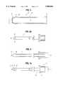
- FIG. 1ais a schematic longitudinal view of the device according to a first embodiment of the invention with a needle inserted in the sleeve;
- FIG. 1bis a schematic longitudinal view of the device according to a second embodiment of the invention with a needle inserted in the sleeve;
- FIG. 2ais a view of only the sleeve according to the first embodiment
- FIG. 2bis a view of only the sleeve according to the second embodiment
- FIG. 3is a view of the inner needle
- FIG. 4is a longitudinal cross section of the sleeve, with an inserted needle not in section;
- FIG. 5is a longitudinal cross section of a distal part of a first embodiment of the sleeve.
- FIG. 6is a cross sectional view of a distal part of a preferred embodiment of the sleeve.
- the biopsy needle assembly of the inventioncomprises a sleeve generally designated with numeral 1, the distal end 5' of which is externally cone shaped or bevelled.
- a handle 2is attached.
- a movable, massive needle 7(FIG. 3) is inserted.
- a handle 3is attached.
- the distal end 5' of the sleeve 1is bevelled, forming a truncated cone portion, and the tip 6 of the needle 7 extending out of the sleeve is also bevelled at essentially the same angle, such that there is formed a penetrating tip 5', 6 on the device as a whole.
- a ring shaped portion 11having the same diameter as the nominal diameter N of the sleeve.
- the ring shaped portion 11merges into the reduced diameter portion 4 via a bevelled portion 12.
- the bevel angle of bevelled portion 12may be 0.1°-80°. It is preferable that the bevel angle be 1°-60°, and more preferably be 5°-45°.
- the sleeve 1 in a first embodiment, shown in FIG. 2a,has a portion 4 with reduced diameter, and having a longitudinal extension from in the vicinity of the distal end over a distance towards the proximal end, whereby the length of the portion 4 corresponds to at least 10%, preferably about 15-75% of the length of the sleeve.
- the thickness of the material in the portion 4 with reduced diameteris about 50-90% of the nominal thickness of the sleeve.
- FIG. 4there is shown a section of the embodiment of FIG. 1a, shown with a solid needle 7 in place.
- the sleeve 1has a uniform inner diameter along its entire length.
- FIG. 5there is shown the distal part of another embodiment of the sleeve, designated with numeral 1.
- the distal end portion 5' of said sleeveis designed exteriorly much the same as the embodiment shown in FIG. 2a. However, it is modified interiorly in that the major lumen 8 of the sleeve, in the embodiment shown in FIG. 5, has a uniform diameter over practically the entire length of the sleeve 1, but the distal portion 9 of said lumen 8 has a reducing diameter.
- the embodiment of FIG. 4has a constant inner diameter over its entire lumen 8. The reduction in diameter with respect to the inner lumen 8, as shown in FIGS.
- sleeve 5 and 6is achieved by mechanically working the distal end of a sleeve "blank", i.e. a tube of steel. This can be done by e.g. placing a rod inside the sleeve blank, said rod having a diameter corresponding to the diameter of the reduction at the distal end. Then said sleeve distal end is exposed to a pressure force by suitable means such that the material essentially plastically flows to adapt to said rod.
- bladei.e. a tube of steel.
- the length of a sleeveis 158 mm, and the length of the portion with reduced outer diameter is 35 mm.
- the nominal outer diameter of the sleeveis 1.7 mm, the nominal inner diameter is 1.4 mm, and the outer diameter of the reduced portion is 1.66 mm.
- the nominal material thickness of the sleeveis 0.15 mm and the material thickness of the reduced portion is thus 0.13 mm.
- the angle of the bevelled outer end surface 5'is suitably 20° but may vary from 17° to 23°.
- the bevel angle of the inner surface 14is not critical but may e.g. amount to 3°-8°.
- the sleeve 1is preferably made of stainless steel, such as SS 2333. During said working process the metal sleeve may be heated to increase plasticity of the material.
- FIG. 6there is shown a distal part of a preferred embodiment of the sleeve 1.
- the initial working of the sleeve 1is identical to the embodiment of FIG. 5, that is the same deformation of the distal end 5' is performed.
- the end portion 5'is first machined at an angle deviating from the vertical for creating an angled cutting edge 15.
- the angle Ais 17°-23° with respect to a vertical plane.
- the material at the end portion 5'is removed by grinding such that the bevel angle is the same around the circumference of the end, e.g. 17°-23° (i.e. the cone angle of the truncated cone thus formed). It is nevertheless conceivable to have angles A in a wider range, e.g. 5°-45°, and thus the numeric values indicated above are not limiting.
- the ring shaped portion 15 in FIG. 6corresponds to the envelope surface of a cylinder having a circular base 16 and an ellipsoid surface 17 of section at the opposite end.
- the needleWhen the device is used, the needle is inserted into the sleeve and the entire assembly is pressed into the tissue.
- the portion having reduced diameterthe friction against the tissue when the needle assembly successively is brought into the tissue becomes smaller, in comparison with known needles not having a corresponding reduction.
- the tissue that has been radially compressed because of the punctureis given the room to expand in the space created by the diameter reduction, and thereby the friction is reduced.
- the inventionis applicable to most available conventional needles for biopsy sampling.
Landscapes
- Health & Medical Sciences (AREA)
- Life Sciences & Earth Sciences (AREA)
- Biomedical Technology (AREA)
- Molecular Biology (AREA)
- Rheumatology (AREA)
- Pathology (AREA)
- Immunology (AREA)
- Engineering & Computer Science (AREA)
- Hematology (AREA)
- Heart & Thoracic Surgery (AREA)
- Medical Informatics (AREA)
- Orthopedic Medicine & Surgery (AREA)
- Surgery (AREA)
- Animal Behavior & Ethology (AREA)
- General Health & Medical Sciences (AREA)
- Public Health (AREA)
- Veterinary Medicine (AREA)
- Infusion, Injection, And Reservoir Apparatuses (AREA)
- Surgical Instruments (AREA)
Abstract
Description
Claims (20)
Applications Claiming Priority (3)
| Application Number | Priority Date | Filing Date | Title |
|---|---|---|---|
| SE9304261 | 1993-12-22 | ||
| SE9304261ASE9304261D0 (en) | 1993-12-22 | 1993-12-22 | Biopsy sampling device |
| PCT/SE1994/001244WO1995017126A1 (en) | 1993-12-22 | 1994-12-22 | Device for biopsy sampling |
Publications (1)
| Publication Number | Publication Date |
|---|---|
| US5868684Atrue US5868684A (en) | 1999-02-09 |
Family
ID=20392189
Family Applications (1)
| Application Number | Title | Priority Date | Filing Date |
|---|---|---|---|
| US08/663,123Expired - LifetimeUS5868684A (en) | 1993-12-22 | 1994-12-22 | Device for hard tissue biopsy sampling |
Country Status (6)
| Country | Link |
|---|---|
| US (1) | US5868684A (en) |
| EP (1) | EP0794733B1 (en) |
| JP (1) | JP3710475B2 (en) |
| DE (1) | DE69432528T2 (en) |
| SE (1) | SE9304261D0 (en) |
| WO (1) | WO1995017126A1 (en) |
Cited By (33)
| Publication number | Priority date | Publication date | Assignee | Title |
|---|---|---|---|---|
| US5976166A (en)* | 1996-12-24 | 1999-11-02 | Nac Co., Ltd. | Claspless stud for piercing |
| US6007496A (en)* | 1996-12-30 | 1999-12-28 | Brannon; James K. | Syringe assembly for harvesting bone |
| US6134467A (en)* | 1997-10-29 | 2000-10-17 | Asahi Kogaku Kogyo Kabushiki Kaisha | Drainage tube introducer for endoscope |
| US6443910B1 (en) | 2000-04-18 | 2002-09-03 | Allegiance Corporation | Bone marrow biopsy needle |
| US6458117B1 (en)* | 2000-01-19 | 2002-10-01 | Kevin Daniel Pollins, Sr. | Intraosseous infusion assembly and method for intraosseous infusion |
| US20030050574A1 (en)* | 2000-04-18 | 2003-03-13 | John Krueger | Bone biopsy instrument having improved sample retention |
| US20030236506A1 (en)* | 2002-06-20 | 2003-12-25 | Eric Schofield | Dual outside diameter cannula for insertion into bone |
| US6730043B2 (en) | 2000-04-18 | 2004-05-04 | Allegiance Corporation | Bone marrow biopsy needle |
| US20040127814A1 (en)* | 2002-12-12 | 2004-07-01 | Carlos Negroni | Biopsy assembly |
| US20050203523A1 (en)* | 2004-03-05 | 2005-09-15 | Wenstrom Richard F.Jr. | Tunnel notcher and guidewire delivery device |
| US20070255281A1 (en)* | 2006-04-27 | 2007-11-01 | Sdgi Holdings, Inc. | Method for use of dilating stylet and cannula |
| US20070255282A1 (en)* | 2006-04-27 | 2007-11-01 | Sdgi Holdings, Inc. | Dilating stylet and cannula |
| US20070260255A1 (en)* | 2006-05-04 | 2007-11-08 | Sdgi Holdings, Inc. | Method for using retractable stylet and cannula combination to form an opening in bone |
| US20070260184A1 (en)* | 2006-05-04 | 2007-11-08 | Sdgi Holdings, Inc. | Retractable stylet and cannula combination |
| US20080140022A1 (en)* | 2006-12-08 | 2008-06-12 | Warsaw Orthopedic, Inc. | Coated Cannula with Protective Tip for Insertion Into a Patient |
| US20090299400A1 (en)* | 2007-11-21 | 2009-12-03 | Becton, Dickinson And Company | Safety stylet |
| US20100030105A1 (en)* | 2005-03-29 | 2010-02-04 | Yasuharu Noishiki | Double needle for medical treatment, bone puncture needle, and bone marrow harvesting device |
| USD647202S1 (en) | 2009-12-21 | 2011-10-18 | Warsaw Orthopedic, Inc. | Bone marrow harvesting device |
| US9402602B2 (en) | 2013-01-25 | 2016-08-02 | Choon Kee Lee | Tissue sampling apparatus |
| US9844362B2 (en) | 2015-01-13 | 2017-12-19 | Covidien Lp | Exchangeable core biopsy needle |
| US10159470B2 (en) | 2014-07-30 | 2018-12-25 | Covidien Lp | Exchangeable core biopsy needle |
| US10182798B2 (en) | 2014-07-30 | 2019-01-22 | Covidien Lp | Exchangeable core biopsy needle |
| US10307070B2 (en) | 2014-04-04 | 2019-06-04 | St. Jude Medical Coordination Center Bvba | Intravascular pressure and flow data diagnostic systems, devices, and methods |
| CN110461246A (en)* | 2017-03-16 | 2019-11-15 | 波士顿科学国际有限公司 | Biopsy needles for access to peripheral lung nodules |
| US10648918B2 (en) | 2011-08-03 | 2020-05-12 | Lightlab Imaging, Inc. | Systems, methods and apparatus for determining a fractional flow reserve (FFR) based on the minimum lumen area (MLA) and the constant |
| CN113855098A (en)* | 2021-10-08 | 2021-12-31 | 安徽医科大学第四附属医院 | A leak-proof bone biopsy |
| US11241154B2 (en) | 2011-05-31 | 2022-02-08 | Lightlab Imaging, Inc. | Multimodal imaging system, apparatus, and methods |
| US20230355078A1 (en)* | 2017-08-29 | 2023-11-09 | Joimax Gmbh | Detection system and method for automatic detection of surgical instruments |
| US11883071B2 (en) | 2016-10-27 | 2024-01-30 | C. R. Bard, Inc. | Intraosseous access device |
| US12082843B2 (en) | 2019-09-27 | 2024-09-10 | Bard Access Systems, Inc. | Step needle for intraosseous access device |
| US12167869B2 (en) | 2020-02-28 | 2024-12-17 | Bard Access Systems, Inc. | Flexible intraosseous obturator |
| US12226123B2 (en) | 2020-07-17 | 2025-02-18 | Bard Access Systems, Inc. | Safety mechanism |
| US12383246B2 (en) | 2020-10-12 | 2025-08-12 | Abbott Cardiovascular Systems, Inc. | Vessel closure device with improved safety and tract hemostasis |
Families Citing this family (4)
| Publication number | Priority date | Publication date | Assignee | Title |
|---|---|---|---|---|
| US6375641B2 (en)* | 1997-10-01 | 2002-04-23 | Dr. Japan Co., Ltd. | Medical anesthetic needle |
| JP4550757B2 (en)* | 2005-03-29 | 2010-09-22 | 泰晴 野一色 | Medical double needle |
| SE0701811L (en) | 2007-08-02 | 2008-08-26 | Novoaim Ab | Surgical kit for fat transplant |
| CH704563B1 (en) | 2011-02-21 | 2015-04-30 | Microport Orthopedics Inc | Patient Specific Proberepositionsblock. |
Citations (24)
| Publication number | Priority date | Publication date | Assignee | Title |
|---|---|---|---|---|
| US1626839A (en)* | 1921-04-28 | 1927-05-03 | Henry W Reese | Catheter |
| US2516492A (en)* | 1950-02-09 | 1950-07-25 | Turkel Henry | Skin biopsy needle |
| US3628524A (en)* | 1969-02-28 | 1971-12-21 | Khosrow Jamshidi | Biopsy needle |
| US3630192A (en)* | 1969-07-14 | 1971-12-28 | Khosrow Jamshidi | Instrument for internal organ biopsy |
| US3850158A (en)* | 1973-07-09 | 1974-11-26 | E Elias | Bone biopsy instrument and method |
| US4258722A (en)* | 1978-12-15 | 1981-03-31 | Ferris Manufacturing Corp. | Disposable biopsy needle, particularly for bone marrow samplings |
| US4306570A (en)* | 1980-08-20 | 1981-12-22 | Matthews Larry S | Counter rotating biopsy needle |
| US4368730A (en)* | 1981-02-12 | 1983-01-18 | Nigel Sharrock | Intravenous catheter |
| US4487209A (en)* | 1981-03-16 | 1984-12-11 | Creative Research And Manufacturing Inc. | Biopsy needle |
| US4543966A (en)* | 1981-06-10 | 1985-10-01 | Downs Surgical Plc | Biopsy needle |
| GB2171537A (en)* | 1985-02-23 | 1986-08-28 | Wolf Gmbh Richard | Shaped optical system shaft for an endoscope |
| US4643196A (en)* | 1984-10-24 | 1987-02-17 | Hakko Electric Machine Works Co., Ltd. | Biopsy needle set |
| EP0296421A1 (en)* | 1987-06-26 | 1988-12-28 | ANGIOMED Aktiengesellschaft | Biopsyneedle |
| EP0427367A1 (en)* | 1989-11-07 | 1991-05-15 | Interventional Technologies Inc | A rotary cutting device |
| US5111828A (en)* | 1990-09-18 | 1992-05-12 | Peb Biopsy Corporation | Device for percutaneous excisional breast biopsy |
| US5122134A (en)* | 1990-02-02 | 1992-06-16 | Pfizer Hospital Products Group, Inc. | Surgical reamer |
| US5234455A (en)* | 1992-02-20 | 1993-08-10 | Arkansas Knee Clinic, P.A. | Lipped cannula and methods of introducing surgical instruments in arthroscopic surgical procedures |
| SE470177B (en)* | 1992-03-23 | 1993-11-29 | Radi Medical Systems | Device for punching in hard tissue and puncture needle |
| US5269316A (en)* | 1991-08-16 | 1993-12-14 | Spitalny Hans Henning | Surgical instrument |
| US5401248A (en)* | 1994-02-22 | 1995-03-28 | Ethicon Endo-Surgery | Seal for trocar assembly |
| US5578006A (en)* | 1992-03-20 | 1996-11-26 | Rudolf Schon | Suction catheter |
| US5595186A (en)* | 1992-04-06 | 1997-01-21 | Alan I. Rubinstein | Bone marrow biopsy needle |
| USRE35459E (en)* | 1991-08-30 | 1997-02-18 | Medtronic, Inc. | Aortic root cannula |
| US5676682A (en)* | 1992-01-06 | 1997-10-14 | Yoon; Inbae | Safety trocar penetrating instrument with conical and/or threaded trocar and safety shield |
- 1993
- 1993-12-22SESE9304261Apatent/SE9304261D0/enunknown
- 1994
- 1994-12-22EPEP95905279Apatent/EP0794733B1/ennot_activeExpired - Lifetime
- 1994-12-22USUS08/663,123patent/US5868684A/ennot_activeExpired - Lifetime
- 1994-12-22WOPCT/SE1994/001244patent/WO1995017126A1/enactiveIP Right Grant
- 1994-12-22JPJP51736495Apatent/JP3710475B2/ennot_activeExpired - Lifetime
- 1994-12-22DEDE69432528Tpatent/DE69432528T2/ennot_activeExpired - Lifetime
Patent Citations (25)
| Publication number | Priority date | Publication date | Assignee | Title |
|---|---|---|---|---|
| US1626839A (en)* | 1921-04-28 | 1927-05-03 | Henry W Reese | Catheter |
| US2516492A (en)* | 1950-02-09 | 1950-07-25 | Turkel Henry | Skin biopsy needle |
| US3628524A (en)* | 1969-02-28 | 1971-12-21 | Khosrow Jamshidi | Biopsy needle |
| US3630192A (en)* | 1969-07-14 | 1971-12-28 | Khosrow Jamshidi | Instrument for internal organ biopsy |
| US3850158A (en)* | 1973-07-09 | 1974-11-26 | E Elias | Bone biopsy instrument and method |
| US4258722A (en)* | 1978-12-15 | 1981-03-31 | Ferris Manufacturing Corp. | Disposable biopsy needle, particularly for bone marrow samplings |
| US4306570A (en)* | 1980-08-20 | 1981-12-22 | Matthews Larry S | Counter rotating biopsy needle |
| US4368730A (en)* | 1981-02-12 | 1983-01-18 | Nigel Sharrock | Intravenous catheter |
| US4487209A (en)* | 1981-03-16 | 1984-12-11 | Creative Research And Manufacturing Inc. | Biopsy needle |
| US4543966A (en)* | 1981-06-10 | 1985-10-01 | Downs Surgical Plc | Biopsy needle |
| US4643196A (en)* | 1984-10-24 | 1987-02-17 | Hakko Electric Machine Works Co., Ltd. | Biopsy needle set |
| GB2171537A (en)* | 1985-02-23 | 1986-08-28 | Wolf Gmbh Richard | Shaped optical system shaft for an endoscope |
| EP0296421A1 (en)* | 1987-06-26 | 1988-12-28 | ANGIOMED Aktiengesellschaft | Biopsyneedle |
| EP0427367A1 (en)* | 1989-11-07 | 1991-05-15 | Interventional Technologies Inc | A rotary cutting device |
| US5122134A (en)* | 1990-02-02 | 1992-06-16 | Pfizer Hospital Products Group, Inc. | Surgical reamer |
| US5111828A (en)* | 1990-09-18 | 1992-05-12 | Peb Biopsy Corporation | Device for percutaneous excisional breast biopsy |
| US5269316A (en)* | 1991-08-16 | 1993-12-14 | Spitalny Hans Henning | Surgical instrument |
| USRE35459E (en)* | 1991-08-30 | 1997-02-18 | Medtronic, Inc. | Aortic root cannula |
| US5676682A (en)* | 1992-01-06 | 1997-10-14 | Yoon; Inbae | Safety trocar penetrating instrument with conical and/or threaded trocar and safety shield |
| US5234455A (en)* | 1992-02-20 | 1993-08-10 | Arkansas Knee Clinic, P.A. | Lipped cannula and methods of introducing surgical instruments in arthroscopic surgical procedures |
| US5578006A (en)* | 1992-03-20 | 1996-11-26 | Rudolf Schon | Suction catheter |
| SE470177B (en)* | 1992-03-23 | 1993-11-29 | Radi Medical Systems | Device for punching in hard tissue and puncture needle |
| US5423824A (en)* | 1992-03-23 | 1995-06-13 | Radi Medical Systems Ab | Method of accessing hard tissue |
| US5595186A (en)* | 1992-04-06 | 1997-01-21 | Alan I. Rubinstein | Bone marrow biopsy needle |
| US5401248A (en)* | 1994-02-22 | 1995-03-28 | Ethicon Endo-Surgery | Seal for trocar assembly |
Cited By (50)
| Publication number | Priority date | Publication date | Assignee | Title |
|---|---|---|---|---|
| US5976166A (en)* | 1996-12-24 | 1999-11-02 | Nac Co., Ltd. | Claspless stud for piercing |
| US6007496A (en)* | 1996-12-30 | 1999-12-28 | Brannon; James K. | Syringe assembly for harvesting bone |
| US6134467A (en)* | 1997-10-29 | 2000-10-17 | Asahi Kogaku Kogyo Kabushiki Kaisha | Drainage tube introducer for endoscope |
| US6458117B1 (en)* | 2000-01-19 | 2002-10-01 | Kevin Daniel Pollins, Sr. | Intraosseous infusion assembly and method for intraosseous infusion |
| US7201722B2 (en) | 2000-04-18 | 2007-04-10 | Allegiance Corporation | Bone biopsy instrument having improved sample retention |
| US20030050574A1 (en)* | 2000-04-18 | 2003-03-13 | John Krueger | Bone biopsy instrument having improved sample retention |
| US6730043B2 (en) | 2000-04-18 | 2004-05-04 | Allegiance Corporation | Bone marrow biopsy needle |
| US6443910B1 (en) | 2000-04-18 | 2002-09-03 | Allegiance Corporation | Bone marrow biopsy needle |
| US20030236506A1 (en)* | 2002-06-20 | 2003-12-25 | Eric Schofield | Dual outside diameter cannula for insertion into bone |
| US20040127814A1 (en)* | 2002-12-12 | 2004-07-01 | Carlos Negroni | Biopsy assembly |
| US9265519B2 (en) | 2004-03-05 | 2016-02-23 | Depuy Mitek, Llc | Tunnel notcher and guidewire delivery device |
| US20050203523A1 (en)* | 2004-03-05 | 2005-09-15 | Wenstrom Richard F.Jr. | Tunnel notcher and guidewire delivery device |
| US8070750B2 (en)* | 2004-03-05 | 2011-12-06 | Depuy Mitek, Inc. | Tunnel notcher and guidewire delivery device |
| US20100030105A1 (en)* | 2005-03-29 | 2010-02-04 | Yasuharu Noishiki | Double needle for medical treatment, bone puncture needle, and bone marrow harvesting device |
| US20070255281A1 (en)* | 2006-04-27 | 2007-11-01 | Sdgi Holdings, Inc. | Method for use of dilating stylet and cannula |
| US20070255282A1 (en)* | 2006-04-27 | 2007-11-01 | Sdgi Holdings, Inc. | Dilating stylet and cannula |
| US20110130759A1 (en)* | 2006-04-27 | 2011-06-02 | Simonton T Andrew | Method for use of dilating stylet and cannula |
| US9066753B2 (en) | 2006-04-27 | 2015-06-30 | Warsaw Orthopedic, Inc. | Dilating stylet and cannula |
| US8372076B2 (en) | 2006-04-27 | 2013-02-12 | Warsaw Orthopedic, Inc. | Method for use of dilating stylet and cannula |
| US7892207B2 (en) | 2006-04-27 | 2011-02-22 | Warsaw Orthopedic, Inc. | Dilating stylet and cannula |
| US7905884B2 (en) | 2006-04-27 | 2011-03-15 | Warsaw Orthopedic, Inc. | Method for use of dilating stylet and cannula |
| US8167899B2 (en) | 2006-05-04 | 2012-05-01 | Warsaw Orthopedic, Inc. | Retractable stylet and cannula combination |
| US7842038B2 (en)* | 2006-05-04 | 2010-11-30 | Warsaw Orthopedic, Inc. | Method for using retractable stylet and cannula combination to form an opening in bone |
| US8257358B2 (en) | 2006-05-04 | 2012-09-04 | Warsaw Orthopedic, Inc. | Method for using retractable stylet and cannula combination to form an opening in bone |
| US8888780B2 (en) | 2006-05-04 | 2014-11-18 | Warsaw Orthopedic, Inc. | Method for using retractable stylet and cannula combination to form an opening in bone |
| US20070260184A1 (en)* | 2006-05-04 | 2007-11-08 | Sdgi Holdings, Inc. | Retractable stylet and cannula combination |
| US20070260255A1 (en)* | 2006-05-04 | 2007-11-08 | Sdgi Holdings, Inc. | Method for using retractable stylet and cannula combination to form an opening in bone |
| US20080140022A1 (en)* | 2006-12-08 | 2008-06-12 | Warsaw Orthopedic, Inc. | Coated Cannula with Protective Tip for Insertion Into a Patient |
| US20090299400A1 (en)* | 2007-11-21 | 2009-12-03 | Becton, Dickinson And Company | Safety stylet |
| US9750529B2 (en)* | 2007-11-21 | 2017-09-05 | Becton, Dickinson And Company | Safety stylet |
| USD647202S1 (en) | 2009-12-21 | 2011-10-18 | Warsaw Orthopedic, Inc. | Bone marrow harvesting device |
| US11241154B2 (en) | 2011-05-31 | 2022-02-08 | Lightlab Imaging, Inc. | Multimodal imaging system, apparatus, and methods |
| US10648918B2 (en) | 2011-08-03 | 2020-05-12 | Lightlab Imaging, Inc. | Systems, methods and apparatus for determining a fractional flow reserve (FFR) based on the minimum lumen area (MLA) and the constant |
| US9402602B2 (en) | 2013-01-25 | 2016-08-02 | Choon Kee Lee | Tissue sampling apparatus |
| US10307070B2 (en) | 2014-04-04 | 2019-06-04 | St. Jude Medical Coordination Center Bvba | Intravascular pressure and flow data diagnostic systems, devices, and methods |
| US11559218B2 (en) | 2014-04-04 | 2023-01-24 | St. Jude Medical Coordination Center Bvba | Intravascular pressure and flow data diagnostic systems, devices, and methods |
| US10182798B2 (en) | 2014-07-30 | 2019-01-22 | Covidien Lp | Exchangeable core biopsy needle |
| US10159470B2 (en) | 2014-07-30 | 2018-12-25 | Covidien Lp | Exchangeable core biopsy needle |
| US9844362B2 (en) | 2015-01-13 | 2017-12-19 | Covidien Lp | Exchangeable core biopsy needle |
| US10758213B2 (en) | 2015-01-13 | 2020-09-01 | Covidien Lp | Exchangeable core biopsy needle |
| US11883071B2 (en) | 2016-10-27 | 2024-01-30 | C. R. Bard, Inc. | Intraosseous access device |
| CN110461246A (en)* | 2017-03-16 | 2019-11-15 | 波士顿科学国际有限公司 | Biopsy needles for access to peripheral lung nodules |
| CN110461246B (en)* | 2017-03-16 | 2023-08-08 | 波士顿科学国际有限公司 | Biopsy needles for access to peripheral lung nodules |
| US20230355078A1 (en)* | 2017-08-29 | 2023-11-09 | Joimax Gmbh | Detection system and method for automatic detection of surgical instruments |
| US12082843B2 (en) | 2019-09-27 | 2024-09-10 | Bard Access Systems, Inc. | Step needle for intraosseous access device |
| US12167869B2 (en) | 2020-02-28 | 2024-12-17 | Bard Access Systems, Inc. | Flexible intraosseous obturator |
| US12226123B2 (en) | 2020-07-17 | 2025-02-18 | Bard Access Systems, Inc. | Safety mechanism |
| US12383246B2 (en) | 2020-10-12 | 2025-08-12 | Abbott Cardiovascular Systems, Inc. | Vessel closure device with improved safety and tract hemostasis |
| CN113855098B (en)* | 2021-10-08 | 2023-11-10 | 安徽省公共卫生临床中心(安徽省传染病医院) | Leakage-proof bone biopsy device |
| CN113855098A (en)* | 2021-10-08 | 2021-12-31 | 安徽医科大学第四附属医院 | A leak-proof bone biopsy |
Also Published As
| Publication number | Publication date |
|---|---|
| JPH09506802A (en) | 1997-07-08 |
| EP0794733A1 (en) | 1997-09-17 |
| DE69432528D1 (en) | 2003-05-22 |
| DE69432528T2 (en) | 2003-12-24 |
| WO1995017126A1 (en) | 1995-06-29 |
| SE9304261D0 (en) | 1993-12-22 |
| EP0794733B1 (en) | 2003-04-16 |
| JP3710475B2 (en) | 2005-10-26 |
Similar Documents
| Publication | Publication Date | Title |
|---|---|---|
| US5868684A (en) | Device for hard tissue biopsy sampling | |
| US4863430A (en) | Introduction set with flexible trocar with curved cannula | |
| US5005585A (en) | Biopsy needle construction | |
| US4177797A (en) | Rotary biopsy device and method of using same | |
| US5057085A (en) | Stabilized aspiration biopsy needle assembly | |
| US5526821A (en) | Biopsy needle with sample retaining means | |
| US5429138A (en) | Biopsy needle with sample retaining means | |
| US5449001A (en) | Biopsy needle | |
| JP4648554B2 (en) | Bone marrow biopsy assembly and bone marrow biopsy collector | |
| US3628524A (en) | Biopsy needle | |
| US4399813A (en) | Apparatus and method for removing a prosthesis embedded in skeletal bone | |
| US4696308A (en) | Core sampling apparatus | |
| US4640296A (en) | Biopsy cannula | |
| US6315737B1 (en) | Biopsy needle for a biopsy instrument | |
| US5423824A (en) | Method of accessing hard tissue | |
| DE69602812T2 (en) | Device for removing fasteners from bones | |
| AU699844B2 (en) | Safety trocar | |
| US20040153005A1 (en) | Bone marrow aspiration device with curved tip | |
| EP2323563B1 (en) | Core biopsy arrangement | |
| JP5465787B2 (en) | Intramedullary systems and methods | |
| US20080200915A1 (en) | Marked tools | |
| JP2002502282A (en) | Drilling guides and measuring instruments | |
| US4927424A (en) | Reamer guide for intramedullary nail placement | |
| US5409462A (en) | Cyst puncture catheter assembly | |
| US20050070907A1 (en) | Method and device for drilling and tapping a bore for a bone screw |
Legal Events
| Date | Code | Title | Description |
|---|---|---|---|
| AS | Assignment | Owner name:RADI MEDICAL SYSTEMS AB, SWEDEN Free format text:(ASSIGNMENT OF ASSIGNOR'S INTEREST) RE-RECORD TO CORRECT THE RECORDATION DATE OF 10-3-96 TO 6-21-96 PREVIOUSLY RECORDED AT REEL 8158, FRAME 0698.;ASSIGNORS:AKERFELDT, DAN;ASTROEM, GUNNAR;AHLSTROEM, HAKAN;REEL/FRAME:008492/0182 Effective date:19960607 | |
| AS | Assignment | Owner name:RADI MEDICAL SYSTEMS AB, SWEDEN Free format text:ASSIGNMENT OF ASSIGNORS INTEREST;ASSIGNORS:AKERFELDT, DAN;ASTROEM, GUNNAR;AHLSTROEM, HAKAN;REEL/FRAME:008158/0698 Effective date:19960607 | |
| STCF | Information on status: patent grant | Free format text:PATENTED CASE | |
| CC | Certificate of correction | ||
| FEPP | Fee payment procedure | Free format text:PAYOR NUMBER ASSIGNED (ORIGINAL EVENT CODE: ASPN); ENTITY STATUS OF PATENT OWNER: SMALL ENTITY | |
| FPAY | Fee payment | Year of fee payment:4 | |
| FPAY | Fee payment | Year of fee payment:8 | |
| FEPP | Fee payment procedure | Free format text:PAYOR NUMBER ASSIGNED (ORIGINAL EVENT CODE: ASPN); ENTITY STATUS OF PATENT OWNER: SMALL ENTITY Free format text:PAYER NUMBER DE-ASSIGNED (ORIGINAL EVENT CODE: RMPN); ENTITY STATUS OF PATENT OWNER: SMALL ENTITY | |
| AS | Assignment | Owner name:RADI MEDICAL DEVICES AB, SWEDEN Free format text:ASSIGNMENT OF ASSIGNORS INTEREST;ASSIGNOR:RADI MEDICAL SYSTEMS AB;REEL/FRAME:021976/0920 Effective date:20081212 | |
| AS | Assignment | Owner name:APRIO MEDICAL AB, SWEDEN Free format text:CHANGE OF NAME;ASSIGNOR:RADI MEDICAL DEVICES AB;REEL/FRAME:022868/0487 Effective date:20090217 | |
| FPAY | Fee payment | Year of fee payment:12 |