US5865749A - Blood flow meter apparatus and method of use - Google Patents
Blood flow meter apparatus and method of useDownload PDFInfo
- Publication number
- US5865749A US5865749AUS08/744,360US74436096AUS5865749AUS 5865749 AUS5865749 AUS 5865749AUS 74436096 AUS74436096 AUS 74436096AUS 5865749 AUS5865749 AUS 5865749A
- Authority
- US
- United States
- Prior art keywords
- signal
- doppler
- blood flow
- phase
- shifted
- Prior art date
- Legal status (The legal status is an assumption and is not a legal conclusion. Google has not performed a legal analysis and makes no representation as to the accuracy of the status listed.)
- Expired - Lifetime
Links
- 230000017531blood circulationEffects0.000titleclaimsabstractdescription159
- 238000000034methodMethods0.000titleabstractdescription20
- 230000000747cardiac effectEffects0.000claimsabstractdescription13
- 230000005284excitationEffects0.000claimsabstract5
- 210000004204blood vesselAnatomy0.000claimsdescription35
- 230000004044responseEffects0.000claimsdescription24
- 238000002604ultrasonographyMethods0.000claimsdescription15
- 230000002441reversible effectEffects0.000claimsdescription7
- 238000012546transferMethods0.000claimsdescription3
- 230000007704transitionEffects0.000claimsdescription3
- 238000005259measurementMethods0.000abstractdescription35
- 238000012545processingMethods0.000abstractdescription17
- 238000010790dilutionMethods0.000abstractdescription6
- 239000012895dilutionSubstances0.000abstractdescription6
- 230000000737periodic effectEffects0.000abstractdescription5
- 230000001154acute effectEffects0.000abstractdescription3
- 230000001684chronic effectEffects0.000abstractdescription3
- 238000010586diagramMethods0.000description23
- 238000005286illuminationMethods0.000description10
- 210000004369bloodAnatomy0.000description9
- 239000008280bloodSubstances0.000description9
- 230000006641stabilisationEffects0.000description8
- 238000011105stabilizationMethods0.000description8
- 241001465754MetazoaSpecies0.000description4
- 230000008901benefitEffects0.000description4
- 230000005540biological transmissionEffects0.000description4
- 238000001514detection methodMethods0.000description4
- 230000000541pulsatile effectEffects0.000description4
- 230000008859changeEffects0.000description3
- 230000007423decreaseEffects0.000description3
- 238000010438heat treatmentMethods0.000description3
- 230000001788irregularEffects0.000description3
- 238000000691measurement methodMethods0.000description3
- 241000124008MammaliaSpecies0.000description2
- 230000003213activating effectEffects0.000description2
- 239000013078crystalSubstances0.000description2
- 230000000694effectsEffects0.000description2
- 239000012530fluidSubstances0.000description2
- 229910052451lead zirconate titanateInorganic materials0.000description2
- 238000002156mixingMethods0.000description2
- 238000011160researchMethods0.000description2
- 238000012935AveragingMethods0.000description1
- 241000700159RattusSpecies0.000description1
- 230000002776aggregationEffects0.000description1
- 238000004220aggregationMethods0.000description1
- 230000003321amplificationEffects0.000description1
- 238000013459approachMethods0.000description1
- 230000002457bidirectional effectEffects0.000description1
- 210000000601blood cellAnatomy0.000description1
- 239000003990capacitorSubstances0.000description1
- 239000000919ceramicSubstances0.000description1
- 238000006243chemical reactionMethods0.000description1
- 230000001427coherent effectEffects0.000description1
- 238000004891communicationMethods0.000description1
- 239000002131composite materialSubstances0.000description1
- 238000001816coolingMethods0.000description1
- 230000008878couplingEffects0.000description1
- 238000010168coupling processMethods0.000description1
- 238000005859coupling reactionMethods0.000description1
- 230000003247decreasing effectEffects0.000description1
- 239000003814drugSubstances0.000description1
- 238000001914filtrationMethods0.000description1
- 238000002513implantationMethods0.000description1
- 238000001727in vivoMethods0.000description1
- 230000010354integrationEffects0.000description1
- HFGPZNIAWCZYJU-UHFFFAOYSA-Nlead zirconate titanateChemical compound[O-2].[O-2].[O-2].[O-2].[O-2].[Ti+4].[Zr+4].[Pb+2]HFGPZNIAWCZYJU-UHFFFAOYSA-N0.000description1
- 238000004519manufacturing processMethods0.000description1
- 239000000463materialSubstances0.000description1
- 238000003199nucleic acid amplification methodMethods0.000description1
- 230000003287optical effectEffects0.000description1
- PIRWNASAJNPKHT-SHZATDIYSA-NpampChemical compoundC([C@@H](C(=O)N[C@@H](CCCNC(N)=N)C(=O)N[C@@H](CCCCN)C(=O)N[C@@H](CCCCN)C(=O)N[C@@H](CC=1C2=CC=CC=C2NC=1)C(=O)N[C@@H](CC(N)=O)C(=O)N[C@@H](CCCCN)C(=O)N[C@@H](CC=1C2=CC=CC=C2NC=1)C(=O)N[C@@H](C)C(=O)N[C@@H](CC(C)C)C(=O)N[C@@H](CO)C(=O)N[C@@H](CCCNC(N)=N)C(N)=O)NC(=O)[C@H](CCC(O)=O)NC(=O)[C@H](CO)NC(=O)[C@H](C)NC(=O)[C@@H](NC(=O)[C@H](CC(O)=O)NC(=O)[C@H](CC(C)C)NC(=O)[C@H](CCCNC(N)=N)NC(=O)[C@H](C)N)C(C)C)C1=CC=CC=C1PIRWNASAJNPKHT-SHZATDIYSA-N0.000description1
- 239000002245particleSubstances0.000description1
- 229920000642polymerPolymers0.000description1
- 241000894007speciesSpecies0.000description1
- 238000001228spectrumMethods0.000description1
Images


Classifications
- A—HUMAN NECESSITIES
- A61—MEDICAL OR VETERINARY SCIENCE; HYGIENE
- A61B—DIAGNOSIS; SURGERY; IDENTIFICATION
- A61B8/00—Diagnosis using ultrasonic, sonic or infrasonic waves
- A61B8/06—Measuring blood flow
- A—HUMAN NECESSITIES
- A61—MEDICAL OR VETERINARY SCIENCE; HYGIENE
- A61B—DIAGNOSIS; SURGERY; IDENTIFICATION
- A61B8/00—Diagnosis using ultrasonic, sonic or infrasonic waves
- A61B8/12—Diagnosis using ultrasonic, sonic or infrasonic waves in body cavities or body tracts, e.g. by using catheters
- A—HUMAN NECESSITIES
- A61—MEDICAL OR VETERINARY SCIENCE; HYGIENE
- A61B—DIAGNOSIS; SURGERY; IDENTIFICATION
- A61B2560/00—Constructional details of operational features of apparatus; Accessories for medical measuring apparatus
- A61B2560/02—Operational features
- A61B2560/0204—Operational features of power management
- A61B2560/0209—Operational features of power management adapted for power saving
- A—HUMAN NECESSITIES
- A61—MEDICAL OR VETERINARY SCIENCE; HYGIENE
- A61B—DIAGNOSIS; SURGERY; IDENTIFICATION
- A61B5/00—Measuring for diagnostic purposes; Identification of persons
- A61B5/0002—Remote monitoring of patients using telemetry, e.g. transmission of vital signals via a communication network
- A61B5/0031—Implanted circuitry
Definitions
- This inventionrelates to estimation of fluid flow, and more particularly to a chronic or acute measurement of blood flow in a blood vessel.
- Ultrasonic Doppler techniquesto measure blood flow velocity and thereby estimate volumetric blood flow.
- Velocity of an objectis often measured using the Doppler effect.
- Single frequency ultrasonic energyis transmitted into an area of tissue containing the blood flow to be measured. This insonification of the area is typically referred to as illumination.
- Resulting ultrasonic energyis reflected, or backscattered, from the illuminated area.
- Energy reflected from moving targets, such as fluid and blood cells,will be shifted in frequency from the illuminating frequency according to the well-known Doppler effect.
- the Doppler shifted frequencyprovides a measure of the blood flow velocity.
- the present inventionincludes a method and apparatus for estimating blood flow or blood flow velocity in a blood vessel over a period of time.
- the methodat least part of the measurement circuits used to estimate blood flow are automatically activated only during the time an estimate is being obtained. At least part of the measurement circuits are automatically deactivated during the time an estimate is not being obtained.
- the steps of activating and deactivating at least part of the measurement circuitsis repeatedly performed sufficiently frequently, either periodically or at irregular intervals, such that the blood flow waveform substantially represents the variable blood flow. Power to at least a portion of the measurement circuits is reduced or interrupted while the measurement circuits are deactivated.
- Measurement of blood flowcan be obtained through various blood flow measurement techniques, including: continuous wave (CW) Doppler flow measurement, pulsed Doppler flow measurement, laser Doppler flow measurement, transit time flow measurement, thermal dilution flow measurement, electromagnetic flow measurement, or other suitable flow measurement technique.
- CWcontinuous wave
- Doppler flow measurementpulsed Doppler flow measurement
- laser Doppler flow measurementlaser Doppler flow measurement
- transit time flow measurementthermal dilution flow measurement
- electromagnetic flow measurementor other suitable flow measurement technique.
- a basebanded Doppler-shifted signalprovides the blood flow estimate.
- a blood flow output signalis derived from the basebanded Doppler-shifted signal and provided as the blood flow estimate.
- the present inventionprovides a strobed blood flow meter, such as an implantable strobed ultrasonic Doppler blood flow meter, having reduced average power consumption, which is advantageous for reducing battery size, extending battery life, and improving signal-to-noise ratio.
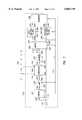
- FIG. 1is a block diagram of one embodiment of the invention.
- FIG. 2is a block diagram illustrating one embodiment of the mixer of FIG. 1 in more detail.
- FIG. 3is a block diagram illustrating one embodiment of the transducer of FIG. 1 in more detail.
- FIG. 4is a block diagram illustrating one embodiment of the control circuit of FIG. 1 in more detail.
- FIG. 5Ais a graph illustrating generally voltage vs. time waveforms for one embodiment in which the invention is operated.
- FIG. 5Bis a graph illustrating generally a velocity vs. time signal in operation of the embodiment of FIG. 5A, but on a compressed time scale with respect to the illustration of FIG. 5A.
- FIG. 6is a block diagram illustrating one embodiment of the present invention in which certain components are turned off during the idle period.
- FIG. 7is a block diagram illustrating another embodiment of the present invention in which certain components are turned off during the idle period.
- FIG. 8is a block diagram illustrating a further embodiment of the present invention in which certain components are turned off during the idle period.
- FIG. 9is a block diagram illustrating in more detail the control circuit of FIG. 8 in more detail.
- FIG. 10is a block diagram illustrating an embodiment of the present invention including an impedance matching network.
- FIG. 11is a block diagram illustrating an embodiment of the present invention including a signal processor.
- FIG. 12is a block diagram illustrating one embodiment of the signal processor of FIG. 11 in more detail.
- FIG. 13is a graph generally comparing the strobed continuous wave and pulse Doppler ultrasonic frequency waveforms.
- FIG. 14is a block diagram illustrating one embodiment of the present invention using transit time techniques of blood flow velocity estimation.
- FIG. 15is an end view of the embodiment illustrated in FIG. 14.
- the present inventionprovides a strobed blood flow meter useful for chronic or acute estimates of blood flow or blood flow velocity and having reduced average power consumption, which has advantages that include reducing battery size and extending battery life.
- estimating volumetric blood flow and blood flow velocityare understood as interchangeable concepts, since estimates of volumetric blood flow are obtained from estimates of blood flow velocity by multiplying blood flow velocity with a known constant cross-sectional area of a blood vessel.
- the cross-sectional area of the blood vesselis unknown, a signal proportional to estimates of blood flow can still be provided from estimates of blood flow velocity since the cross-sectional area of the blood vessel is assumed to be relatively constant.
- strobingis defined as repeatedly estimating blood flow velocity during a period of interest, as discussed below.
- the period of interest for strobingmay be one or more such cardiac cycles.
- certain embodiments of an artificial heart pumpmay be implemented without the periodic pulsing associated with a heartbeat. In such systems, it may still be desirable to repeatedly estimate blood flow velocity over some other period of interest.
- the present inventionencompasses strobing or automatically activating certain portions of the blood flow meter during an active period in order to obtain an ultrasonic Doppler blood flow velocity estimate, and later automatically deactivating these portions of the blood flow meter during an idle time between such estimates.
- Strobing according to the present inventionincludes a wide variety of blood flow measurement techniques, including, but not limited to: ultrasonic Doppler blood flow measurement, such as both continuous wave (CW) and pulsed Doppler blood flow measurements; transit time measurements; electromagnetic flow measurements; thermal dilution measurements; and laser Doppler measurements, each of which is described further below.
- ultrasonic Doppler blood flow measurementsuch as both continuous wave (CW) and pulsed Doppler blood flow measurements
- transit time measurementssuch as both continuous wave (CW) and pulsed Doppler blood flow measurements
- electromagnetic flow measurementssuch as thermal dilution measurements
- laser Doppler measurementseach of which is described further below.
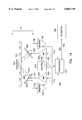
- FIG. 1is a block diagram illustrating one embodiment of the present invention.
- strobed ultrasonic blood flow meter 100is capable of being implanted in a human or animal subject for measurement of blood flow in blood vessel 105.
- Blood flow meter 100comprises oscillator 110, which is a sine or square wave oscillator operating at a carrier frequency in an ultrasonic region of the frequency spectrum, typically in the 5-20 MHz range, though other frequencies are also possible.
- the ultrasonic sine or square wave output signal of oscillator 110 at node 115is referred to as a carrier signal.
- the carrier signal frequency at node 115is in the ultrasonic frequency range, and is electrically coupled to a control circuit 120 at control circuit oscillator input 125.
- Control circuit 120produces at control circuit output 130 a resulting electrical strobed ultrasonic-frequency signal (shown as signal 145V in FIG. 5A) which is electrically coupled to amplifier input 135 of power amplifier 140 through node 145.
- amplifier 140produces a resulting electrical strobed amplified ultrasonic-frequency signal at amplifier output 150, which is electrically coupled through node 165 to transducer electrical input 155 of transducer 160.
- transducer 160provides, at transducer ultrasound output 170, ultrasonic energy that is mechanically or acoustically coupled to tissue including blood vessel 105.
- providing ultrasonic energy, insonifying, and insonatingare all referred to generally as illuminating.
- Illumination of blood vessel 105results in a reflected Doppler-shifted ultrasound signal, also referred to as a backscattered signal, that is received at transducer ultrasound input 175, and converted by transducer 160 into a Doppler-shifted electrical signal at transducer electrical output 180.
- the Doppler-shifted electrical signalis electrically coupled through node 195 to receiver input 185 of receiver 190, which provides a buffered Doppler-shifted signal in response thereto at receiver output 200.
- Mixer 205receives the buffered Doppler-shifted signal at mixer input 210 through node 215. Mixer 205 also receives through node 115 the carrier signal of oscillator 110 at mixer oscillator input 220. Mixer 205 performs a demodulation function by quadrature mixing, as described below, producing an in-phase (I) signal at in-phase (I) output 225 and a phase-shifted (Q) signal, which is 90 degrees out of phase with respect to the I signal, at phase-shifted (Q) output 230.
- the I and Q signalseach have components that include difference and sum frequency components that are approximately equal to the respective difference and sum of the frequencies of the carrier signal and the buffered Doppler-shifted signal.
- the I and Q signalsmay also contain a carrier frequency component, also referred to as carrier feedthrough.
- the I signalis electrically coupled through node 235 to a first low pass filter input 240 of first low pass filter 245.
- First low pass filter 245removes the carrier feedthrough and the sum frequency components of the I signal, and provides the difference frequency component at the first low pass filter output 250.
- the difference frequency component at the first low pass filter output 250is referred to as the basebanded in-phase Doppler signal, or the basebanded I Doppler signal.
- the Q signalis electrically coupled through node 255 to a second low pass filter input 260 of second low pass filter 265.
- Second low pass filter 265removes the carrier feedthrough and the sum frequency components of the Q signal and provides the difference frequency component at the second low pass filter output 270.
- the difference frequency component at the second low pass filter output 250is referred to as the basebanded phase-shifted Doppler signal, or the basebanded Q Doppler signal.
- the basebanded I and Q Doppler signalsare electrically coupled through respective nodes 275 and 280 to respective inputs of telemetry circuit 285.
- the basebanded I and Q Doppler signalsare remodulated with a telemetry carrier frequency for transmission to a remote telemetry device 282, such as an external telemetry receiver.
- a remote telemetry device 282such as an external telemetry receiver.
- an analog velocity output signalis produced, which is encoded, such as by pulse position modulation, for transmission to remote telemetry device 282.
- telemetry circuit 285allows transmission of the signals corresponding to the basebanded I and Q Doppler signals from implanted blood flow meter 100 to a remote telemetry device 282 for further processing.
- this further processingincludes velocity determination according to the well-known Doppler equation, illustrated in Equation (1). ##EQU1##
- Equation (1)v is the blood flow velocity to be determined; f d is the (basebanded) received Doppler shifted frequency reflected from the blood flow; C is the speed of sound in the medium, e.g. tissue; f c is the carrier frequency; and ⁇ is the angle formed by the velocity vector of the blood flow and the path along which the illuminating ultrasonic energy is provided.
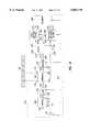
- FIG. 2is a block diagram illustrating one embodiment of mixer 205 in more detail.
- mixer 205includes quadrature phase splitter 300, first multiplier 305, and second multiplier 310.
- Splitter 300receives, through node 115, the carrier signal at splitter input 315, and produces in response thereto a resulting in-phase carrier signal at node 320 and a phase-shifted carrier signal at node 325 that is phase-shifted by 90 degrees with respect to the in-phase carrier signal.
- the in-phase carrier signal at node 320 and the phase-shifted carrier signal at node 325are substantially quadrature balanced, i.e. they are substantially matched in amplitude, and have a phase difference which is very close to 90 degrees.
- the buffered Doppler signal at node 215is multiplied at first multiplier 305 by the in-phase carrier signal at node 320 to produce the I signal at node 235.
- the buffered Doppler signal at node 215is also multiplied at second multiplier 310 by the phase-shifted carrier signal at node 325 to produce the Q signal at node 255.
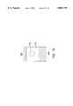
- FIG. 3is a block diagram illustrating one embodiment of transducer 160 in more detail, in relation to blood vessel 105.
- transducer 160includes ultrasound transmit transducer 330 and ultrasound receive transducer 335.
- Transmit and receiver transducers 330 and 335are preferably single piston piezoelectric transducers, comprised of materials such as lead zirconate titanate (PZT) crystal or composite materials. Other piezoelectric crystal, ceramic, or polymer, or any other suitable transducer may also be used.
- PZTlead zirconate titanate
- Transmit transducer 330receives the electrical strobed amplified ultrasonic-frequency signal at input 155 and provides, or launches, continuous wave (CW) ultrasonic energy at transducer ultrasound output 170 for illumination of blood vessel 105. Illumination of blood vessel 105 results in a reflected Doppler-shifted ultrasound signal at transducer ultrasound input 175 that is received by receive transducer 335 and converted into an electrical received Doppler-shifted signal at transducer electrical output 180.
- CWcontinuous wave
- FIG. 4is a block diagram illustrating one embodiment of control circuit 120 in more detail.
- control circuit 120includes sine wave to square wave converter 350, digital control logic 355, and strobing switch 360.
- Converter 350receives the carrier signal at node 115 and provides to digital control logic 355 a square wave clock signal at node 365, which can be divided down to lower frequencies if desired.
- Converter 350is omitted if oscillator 110 is a square wave, rather than a sine wave oscillator.
- Logic 355provides a periodic strobing control signal at node 370, also available at strobing control signal output 371, to control the conductance of the carrier signal at node 115 through strobing switch 360 to control circuit output 130.
- the periodic strobing control signal at node 370could alternatively be provided at irregular intervals.
- a resulting electrical strobed ultrasonic-frequency signalis provided through node 145 for amplification by amplifier 140 and conversion into ultrasound energy by transducer 160.
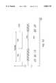
- FIG. 5Ais a voltage vs. time graph illustrating generally timing in one embodiment in which the present invention is operated.
- FIG. 5Aincludes strobing control signal 370V at node 370 and the strobed ultrasonic frequency signal 145V at node 145.
- a corresponding velocity vs. time graphis illustrated in FIG. 5B, but with time illustrated on a compressed time scale with respect to that in FIG. 5A.
- strobing control signal 370is a periodic control signal having a corresponding strobing period, t strobe .
- the strobing periodis comprised of an active period, t on , and an idle period, t off .
- the carrier frequency signal at node 115is conducted to node 145 through the strobing switch 360, as illustrated during the corresponding portion of the strobed ultrasonic frequency signal 145V.
- the carrier frequency signal at node 115is isolated from node 145 by the strobing switch 360, as illustrated during the corresponding portion of the strobed ultrasonic frequency signal 145V.
- Blood vessel 105is illuminated during each active period of the strobing control signal 370V, as illustrated in FIG. 5A. Velocity is determined near the end of each active period of the strobing control signal 370V, such as at times t 1 , t 2 , and t 3 , as illustrated in FIGS. 5A and 5B.
- Blood velocitywill vary depending on the size and physiological location of the blood vessel 105 being measured. Blood velocity will also vary as a function of time during the cardiac cycle, i.e. during and between successive heartbeats.
- One embodiment of the present inventionuses a programmably adjustable strobing frequency, which is the inverse of the strobing period.
- the strobing frequencyshould be high enough to provide a representative estimated velocity vs. time waveform both during the cardiac cycle and over many cardiac cycles. For example, in most larger mammals, heart rate varies from between 40 to 200 beats per minute.
- a strobing frequency of 50 Hzrespectively provides 75 and 15 estimated velocity data points for each of these respective heart rates. For smaller mammals, such as rats, heart rate may approach 400 beats per minute. Increasing strobing frequency to 100 Hz would still allow 15 estimated velocity data points for this case.
- the particular strobing frequencymay be selected to obtain the desired time resolution of velocity estimates.
- the desired time resolution of velocity estimatesmay in turn be selected to accommodate the expected rate of change of blood flow velocity in the blood vessel.
- the rate of change of the blood flow velocityis typically higher for an arterial blood vessel 105 that is more proximal to the heart than for an arterial blood vessel 105 that is more distal from the heart or for a venal blood vessel 105.
- t strobewill exceed t on . But the maximum value of t strobe will depend on many factors, including whether an accurate reconstruction of the velocity waveform is needed or whether the velocity estimates are used only to determine blood flow, such that fewer estimates per cardiac cycle may suffice.
- active period, t onis minimized to minimize average power consumption or to obtain other advantages, as described below.
- the minimum active periodis typically longer than some combination of: a system bandwidth; a stabilization time; and a mean-frequency estimation time.
- the system bandwidthis defined as the inverse of the maximum expected basebanded I and Q Doppler signal frequencies, which can be calculated from the well-known Doppler equation for a particular blood velocity.
- the stabilization timeis the time required to power up and stabilize certain electronic circuits which are powered down during the idle period.
- the required stabilization timemay be dominated by, for example, the filter time-constants of first and second low pass filters 245 and 265, if these filters were powered down during the idle period.
- the required stabilization timemay be dominated by the charging of a power supply output capacitor from which power is supplied to those electronic circuits that were turned off during the idle period.
- Separate control signalsmay be provided to individual electronic circuits to tailor the time that the circuits are powered to meet their individual stabilization requirements.
- first and second low pass filters 245 and 265may be turned on prior to providing the electrical signal to drive transducer 160 to accommodate longer stabilization time requirements of first and second low pass filters 245 and 265.
- the mean frequency estimation timeis determined by the number of samples of the basebanded I or Q Doppler signals at respective nodes 275 and 280 that must be acquired to accurately estimate the blood velocity for a particular velocity estimate.
- the mean frequency estimation timedepends, in turn, on the particular mean frequency estimation technique used.
- sophisticated digital signal processing techniquesare used to extract a relatively accurate mean frequency estimate from as few as 8 of the samples.
- zero-cross detection techniquesare used to provide a root mean square (rms) reading of mean frequency from more than 100 samples.
- the present inventionuses strobed ultrasonic energy, which advantageously reduces its average power consumption. This is particularly important when power is drawn from a fixed resource, such as a battery, which is implanted in vivo together with the electronics of blood flow meter 100 and cannot be easily replaced. In such situations, the reduced average power consumption of the present invention is critical for extending battery life of blood flow meter 100.
- the average power consumption of the present inventionis illustrated by Equation (2). ##EQU2##
- Equation (2)P on is the power consumption during the active period and P off is the power consumption during the idle period. As explained below, most of the electronics of blood flow meter 100 are powered on during the active period, but only a subset of these electronics are powered on during the idle period. For this reason, P on exceeds P off . Thus, as illustrated in Equation (2), average power consumption is minimized by: reducing the duration of the active period; and, increasing the strobing period; and, decreasing both P on and P off , particularly P on .
- FIG. 6is a block diagram illustrating one embodiment of the present invention in which only amplifier 140 and telemetry 285 are turned off during the idle period.
- the strobing control signal at node 370is electrically coupled to switchably control the conductances between each of amplifier 140 and telemetry 285 blocks and their respective power supplies.
- Transducer 160typically does not draw any bias current, but use of any transducer that does draw bias current could similarly have its bias current switchably controlled by strobing control signal 370. By leaving other blocks powered during the idle period, stabilization time is reduced, as described above. However, this embodiment does not minimize average power consumption as much as other possible embodiments.
- FIG. 7is a block diagram illustrating another embodiment of the present invention in which amplifier 140, receiver 190, mixer 205, first and second low pass filters 245 and 265, and telemetry 285 are all turned off during the idle period.
- the strobing control signal at node 370is electrically coupled to switchably control, either independently or in groups, the conductances between each of amplifier 140, receiver 190, mixer 205, first and second low pass filters 245 and 265, and telemetry 285 and their respective power supplies. Since more components are powered down during the idle period, this embodiment decreases average power consumption further from that of FIG. 6, but stabilization time may be increased, as explained above.
- FIG. 8is a block diagram illustrating another embodiment of the present invention in which oscillator 110, amplifier 140, receiver 190, mixer 205, first and second low pass filters 245 and 265, and telemetry 285 are all turned off during the idle period.
- the strobing control signal at node 370is electrically coupled to switchably control, either independently or in groups, the conductances between each of oscillator 110, amplifier 140, receiver 190, mixer 205, first and second low pass filters 245 and 265, and telemetry 285 and their respective power supplies.
- FIG. 8uses a control circuit 400, which is illustrated in more detail in FIG. 9. Since more components are powered down during the idle period, this embodiment decreases average power consumption further from that of FIGS. 6-7.
- FIG. 9is a block diagram illustrating in more detail the control circuit 400 of FIG. 8.
- a separate timing generator 410is provided for coupling a clock signal through node 365 to digital control logic 355.
- the timing generator 410also remains powered during the idle period.
- Timing generator 410is capable of being operated at a lower frequency than the ultrasonic frequencies of oscillator 110. Use of timing generator 410 allows the higher frequency oscillator 110 to be powered down during the idle period. This results in further average power savings in some implementations of the present invention.
- the invention described above in FIGS. 1-9provides a method of estimating the velocity of blood flow in a blood vessel. At least part of the measurement circuits are automatically activated only during the time an estimate is being obtained. At least part of the measurement circuits are deactivated during the time an estimate is not being obtained. These steps are performed repeatedly to provide a sequence of blood flow estimates forming a blood flow waveform indicative of blood flow. More than one estimate is required to obtain the blood flow waveform.
- ultrasonic energyis repeatedly applied to the blood flow in the blood vessel, either periodically or at irregular time intervals over a period of time, such as during all or a portion of one or more cardiac cycles. A portion of the applied energy is reflected from the blood flow to produce a reflected ultrasonic energy signal. The reflected ultrasonic energy is received for further processing from which blood flow velocity is measured. Electronic circuits are powered off or down between the repeated applications of ultrasonic energy, thereby allowing increased levels of illumination while maintaining or reducing average power consumption.
- one embodiment of the present inventionuses strobed ultrasonic energy, which advantageously reduces its average power consumption because portions of the present invention are powered off between strobing instances.
- This advantage, or a portion thereof,may be traded for improved signal-to-noise ratio (SNR), which is also a desirable characteristic for accurate measurement of blood flow velocity.
- SNRsignal-to-noise ratio
- transducer 160is capable of providing higher level illumination of blood vessel 105 than in a conventional system, because strobed ultrasonic energy is used, i.e. the higher level illumination is limited to a shorter duration. Since blood vessel 105 is illuminated at a higher level, more reflected energy is available for detection, thereby improving the SNR.
- Similar signal processing improvementsare also available, for example, by using higher supply currents for shorter durations in those other blocks that are capable of being powered down during the idle period, such as receiver 190, mixer 205, and first and second low pass filters 245 and 265. These signal processing improvements obtained from higher current levels for shorter durations include better noise performance and higher bandwidth. These improvements provided by the present invention are particularly advantageous for the receiver 190 and mixer 205 blocks, which require bandwidths capable of accommodating a Doppler-shifted signal centered around the 5-20 MHz carrier frequency. Thus, the strobed ultrasonic blood flow velocity measurements of the present invention offer considerable advantages in addition to reduced average power consumption.
- the currentcan be elevated by a factor of 7.75 in the strobed CW Doppler system without increasing the average power consumption over a conventional CW Doppler system.
- FIG. 10is a block diagram illustrating another embodiment of the present invention in which an impedance matching network 450 has been interposed between amplifier output 150 and transducer electrical input 155.
- Network 450includes passive impedance matching components to maximize power transfer between amplifier 140 and transducer 160 at the carrier frequency, where amplifier 140 typically presents an impedance that is unmatched to that of transducer 160.
- the impedance matching networkresults in more efficient power transfer at the output of network 450 at node 165B for the strobed CW Doppler system of the present invention over a conventional CW Doppler system, as illustrated in Example 2.
- Example 2Z out is the output impedance of amplifier 140 at amplifier output 150 at the ultrasonic carrier frequency; Z tran is the impedance of transducer 160 at the carrier frequency; Z network is the impedance matching ratio of network 450; I amp is the peak output current of amplifier 140; V amp is the peak-to-peak output voltage of amplifier 140; P amp is the power output of amplifier 140; P transducer is the power input of transducer 160; and, V transducer is the peak-to-peak input voltage of transducer 160.
- Example 2the conventional CW Doppler system is operated continuously, and the strobed CW Doppler system is operated at a 10% duty cycle (t on /t strobe ) with the negligible current during the idle period.
- amplifier 140 and network 450 of the strobed Doppler system of FIG. 10allow higher power output from amplifier 140, and a higher input voltage of transducer 160. This produces a higher level illumination, resulting in more reflected ultrasonic energy, and thereby improving the SNR.
- FIGS. 1-10illustrate various embodiments of the present invention in which the basebanded I and Q Doppler signals are telemetered to other circuits for further processing to determine the blood flow velocity estimate.
- the basebanded I and Q Doppler signalsare telemetered from an implanted portion of the blood flow meter 100 to accompanying external circuits for further processing.
- signal processing of the basebanded I and Q Doppler signalscan also be carried out within the implanted blood flow meter 100.
- FIG. 11is a block diagram illustrating an embodiment of the present invention in which a signal processor 470 is contained within the implanted blood flow meter 100.
- signal processor 470receives the basebanded I and Q Doppler signals at respective nodes 275 and 280, and produces a blood flow output signal or velocity output signal representing the estimated blood flow velocity.
- the velocity output signalis electrically coupled through node 475 to telemetry 285, where it is transmitted from the implanted blood flow meter 100 to an external receiver.
- FIG. 12is a block diagram illustrating one embodiment of signal processor 470 that is particularly useful in applications having a single-ended power supply, such as a battery in the implantable blood flow meter 100 of the present invention.
- signal processor 470contains a voltage reference 500, which provides a stable output bias voltage at node 505 to a first input of each of first and second amplifiers 510 and 520 and first and second zero cross detectors 530 and 540.
- First and second amplifiers 510 and 520provide gain, or provide both gain and level-shifting. First and second amplifiers may also be used to provide bandpass filtering.
- a second input of first amplifier 510receives the basebanded I Doppler signal at node 275.
- a second input of second amplifier 520receives the basebanded Q Doppler signal at node 280.
- First amplifier 510provides a buffered basebanded I Doppler signal at node 545 to a second input of first zero cross detector 530.
- Second amplifier 520provides a buffered basebanded Q Doppler signal at node 550 to a second input of second zero cross detector 540.
- First and second zero cross detectors 530 and 540provide first and second zero cross outputs at respective nodes 555 and 560.
- the first and second zero cross outputs at respective nodes 555 and 560each change logic state in response to the voltage of respective buffered I and Q Doppler signals passing through the bias voltage at node 505.
- Each of the resulting pulsatile voltages waveforms at the first and second zero cross outputsis approximately 90 degrees out of phase with the other, and is at the basebanded Doppler frequency.
- Quadrature encoder 565receives the first and second zero cross outputs at respective nodes 555 and 560.
- the 90 degree phase difference between the voltage waveforms at nodes 555 and 560make it possible to determine their phase relationship at each logic voltage transition of these voltage waveforms at nodes 555 and 560.
- Quadrature encoder 565contains logic circuitry for determining the phase relationship between the first and second zero cross outputs at nodes 555 and 560, and does so at each voltage transition at each of nodes 555 and 560. In response to each such determination, quadrature encoder 565 provides a fixed-duration voltage pulse to only one of forward node 570 or reverse node 575.
- Differential frequency-to-voltage converter 580receives voltage pulses at each of the respective forward and reverse nodes 570 and 575, and provides a resulting blood flow output signal such as the analog velocity output signal at node 475.
- converter 580provides charge integration of the fixed-duration voltage pulses at each of the respective forward and reverse nodes 570 and 575, and provides the resulting blood flow output signal in response thereto.
- the charge of the voltage pulses at the forward node 570incrementally increases the velocity output signal at node 475, and the charge of the voltage pulses at the reverse node 575 incrementally decreases the velocity output signal at node 475.
- Converter 580could also be implemented as an up-down counter providing an output count representative of the velocity output signal. Voltage pulses received at forward node 570 increment the output count, and voltage pulses received at reverse node 575 decrement the output count, or vice versa.
- signal processor 470is capable of providing, using a single-ended power supply, an analog velocity output signal at node 475 containing both magnitude and directional information of blood flow velocity.
- the analog velocity output signal at node 475can be repeatedly sampled to provide a sequence of blood flow estimates forming a blood flow waveform indicative of blood flow.
- the analog velocity output signal at node 475 or the samples derived therefromcan be further processed and transmitted from the implanted blood flow meter 100.
- FIGS. 1-12illustrate various bidirectional embodiments of the present invention that are capable of determining the magnitude and direction of blood flow velocity. If direction information is not needed, a unidirectional embodiment of the present invention could be used. In a unidirectional embodiment of the present invention, one of the I or Q channels is omitted. In mixer 205, a quadrature phase splitter 300 is omitted and only one of first and second multipliers 305 and 310 is needed. In signal processor 470, quadrature encoder 565 is replaced by a monostable oscillator (one-shot) providing a fixed-duration pulse, and differential frequency-to-voltage converter 580 is replaced by a single-ended frequency-to-voltage converter.
- a monostable oscillatorone-shot
- a strobed ultrasonic Doppler blood flow meteri.e. a strobed continuous wave (CW) ultrasonic Doppler blood flow meter, referred to as a strobed CW Doppler blood flow meter.
- CWcontinuous wave
- the present inventionis also broadly applicable to any embodiment of a strobed ultrasonic Doppler blood flow meter and its method of use.
- the inventionencompasses the use of a strobed ultrasonic pulsed Doppler blood flow meter, referred to as a strobed pulsed Doppler blood flow meter.
- the strobed pulsed Doppler embodimentalso periodically illuminates a blood vessel by a transducer, but each illumination comprises bursts of pulsatile (or pulse train) ultrasonic-frequency energy. Each burst of ultrasonic-frequency energy from a particular illumination is reflected, or backscattered, from the blood flow and typically subsequently detected at the same transducer. Samples of the resulting electrical signal, each corresponding to a burst of pulsatile ultrasonic-frequency energy, are used to estimate mean frequency. A resulting blood flow velocity estimate is produced from the aggregation of mean frequency estimations within a particular strobing.
- FIG. 13illustrates generally a comparison of the strobed ultrasonic frequency signal waveforms used in each of the strobed CW and strobed pulsed Doppler embodiments.
- the strobing control signal 370Villustrates generally the active and idle periods in relation to the strobing period.
- the CW embodimentprovides an ultrasonic frequency signal 145V continuously over the entire active period or at least some portion thereof.
- the strobed pulsed Doppler embodimentprovides a pulsed ultrasonic frequency signal 600 that typically contains more than one burst of pulsatile ultrasonic-frequency energy over the active period or at least some portion thereof.
- both of the above-described ultrasonic blood flow metershave characteristics that include: repeatedly illuminating the blood vessel with ultrasonic energy during a cardiac cycle; repeatedly receiving during the cardiac cycle an ultrasonic energy signal, which contains Doppler-shifted frequencies corresponding to a blood flow velocity estimate, reflected from the blood flow; and, processing the received ultrasonic energy signal to obtain the blood flow velocity estimate from the Doppler-shifted frequencies contained therein.
- each strobing instancecorresponds to a resulting blood flow velocity estimate.
- the above-described embodimentsdescribe a blood flow meter that estimates blood flow velocity by strobed Doppler measurements of backscattered ultrasonic energy.
- the strobed blood flow meter according to the present inventionalso includes other techniques of estimating blood flow velocity, including, but not limited to: transit time measurements, electromagnetic flow measurements, thermal dilution measurements, and laser Doppler measurements, each of which is described further below.
- FIG. 14is a generalized schematic illustration of one embodiment of a transit time measurement of blood flow velocity that is encompassed by the present invention.
- First and second transducers 650 and 655are configured for ultrasonic communication therebetween via an acoustic reflector 660.
- a first ultrasonic impulse 665is launched from first transducer 650, reflected from reflector 660, and received at second transducer 655.
- a second ultrasonic impulse 670is launched from second transducer 655, reflected from reflector 660, and received at first transducer 650.
- FIG. 14illustrates the case where first impulse 665 has a directional component in the same direction as the blood flow in blood vessel 105, and second impulse 670 has a directional component opposite the direction of blood flow in blood vessel 105.
- a travel time of second impulse 670 from second transducer 655 to first transducer 650is longer than a travel time of first impulse 665 from first transducer 650 to second transducer 655.
- Blood flow velocityis calculated from the difference in transit times of the first and second impulses 665 and 670 respectively.
- the inventionincludes a control circuit 675 for providing a strobed ultrasonic frequency signal to each of respective first and second amplifiers 680 and 685 through respective nodes 690 and 695.
- Control circuit 675optionally provides power control signals to respective first and second receivers 700 and 705 through respective nodes 710 and 715.
- First and second amplifiers 680 and 685respectively, provide an amplified strobed ultrasonic frequency signal at respective nodes 720 and 725 to respective first and second transducers 650 and 655, which provide the first and second impulses 665 and 670 in response thereto.
- First and second transducers 650 and 655also receive respective second and first impulses 670 and 665, as described above, and provide resulting electrical signals to respective first and second receivers 700 and 705 through respective nodes 730 and 735.
- First and second receivers 700 and 705, respectively,provide buffered electrical signals to processing circuit 740 through respective nodes 745 and 750.
- Processing circuit 740calculates blood flow velocity from the difference in transit times of the first and second impulses 665 and 670 respectively, and provides through node 755 a signal containing blood flow velocity information to telemetry device 760 for transmission to a remote telemetry device.
- Control circuit 675optionally provides a power control signal to processing circuit 740 through node 765 for reducing or removing power from processing circuit 740 between transit time estimates of blood flow velocity. As described above, control circuit 675 may also optionally provide a power control signal to telemetry device 760 to reduce or remove power from telemetry device 760 when it is not transmitting a transit time estimate of blood flow velocity.
- FIG. 15illustrates an end view of the configuration of FIG. 14.
- first and second transducers 650 and 655, respectively, and reflector 660are arranged such that first and second impulses 665 and 670, respectively, each provide an insonification area 770 that includes the entire area of blood vessel 105, such that an average estimate of blood flow over the area of blood vessel 105 is provided.
- the transit time estimate of blood flow velocitymay also be improved by averaging multiple transit time measurements to provide a single estimate of blood flow velocity.
- control circuit 675reduces or removes power from other circuits between each series of transit time measurements used to provide a blood flow velocity estimate.
- a sequence of blood flow estimatesforms a waveform representative of blood flow over a period of time.
- the present inventionalso includes the use of electromagnetic flow techniques to estimate blood flow velocity.
- first and second electrodesare disposed across an interposed blood vessel such that the blood flow is in a direction that is substantially orthogonal to a vector between the first and second electrodes.
- a permanent magnet or electromagnetis used to create a magnetic field through the blood vessel in a direction that is substantially orthogonal to both the direction of blood flow and the vector between the first and second electrodes.
- the inventionuses the above-described strobing technique to reduce or remove power between blood flow estimates to circuits within the blood flow meter, such as to the electromagnet, if any, or to sensing and processing circuits that detect the voltage difference between the first and second electrodes, or to telemetry circuits that transmit electromagnetic flow estimates of blood flow velocity to a remote telemetry device.
- the present inventionalso includes the use of thermal dilution techniques to estimate blood flow.
- a heateris used to pulsedly heat the blood, and the heated blood pulse is detected by a temperature sensor located at a known distance from the point of heating in the direction of the blood flow.
- Volumetric blood flowis calculated from the time between the heating of the blood pulse and the detection of the blood pulse.
- heated blood pulsesare typically introduced and detected to produce a more accurate blood flow estimate.
- a single thermistoris used for both heating and detection.
- a heated thermistoris introduced into the blood vessel such that it is in thermal contact with the blood flow, and cooling of the thermistor is effected by the blood flow. Blood flow at a higher velocity cools the thermistor at a higher rate than blood flow at a lower velocity.
- the energy delivered to the thermistor to maintain the thermistor at a constant temperatureis proportional to blood flow velocity.
- the thermistorcan be heated to a known temperature, and the time required to cool the thermistor to a second, lower temperature will be inversely proportional to blood flow.
- measuring circuits in the above-described thermal dilution embodimentsare automatically activated only during estimation of blood flow, and are powered down or off between estimates of blood flow.
- a resulting volumetric blood flow vs. time waveform constructed from the sequence of blood flow estimatesis thereby obtained at a reduced power consumption by application of the strobing technique of the present invention.
- the present inventionalso includes the use of laser Doppler techniques to estimate blood flow.
- the blood flowis illuminated with a coherent monochromatic light source signal.
- a resulting backscattered Doppler-shifted light signalis received at an optical detector, and demodulated such as by mixing with the monochromatic light source signal.
- Blood flow velocityis estimated from a resulting basebanded Doppler-shifted frequency of the received light signal.
- measuring circuitsoptionally including the monochromatic light source, are automatically activated only during estimation of the blood flow velocity. These measuring circuits are deactivated, i.e. powered down or off between estimates of blood flow velocity.
- a resulting velocity vs. time waveform constructed from the sequence of blood flow velocityis thereby obtained at a reduced power consumption by application of the strobing technique of the present invention.
- the present inventionprovides an strobed blood flow meter, such as an implantable strobed ultrasonic Doppler blood flow meter, having reduced average power consumption, which is advantageous for reducing battery size, improving signal-to-noise ratio, and extending battery life.
Landscapes
- Health & Medical Sciences (AREA)
- Life Sciences & Earth Sciences (AREA)
- Medical Informatics (AREA)
- Animal Behavior & Ethology (AREA)
- Nuclear Medicine, Radiotherapy & Molecular Imaging (AREA)
- Pathology (AREA)
- Radiology & Medical Imaging (AREA)
- Engineering & Computer Science (AREA)
- Biomedical Technology (AREA)
- Heart & Thoracic Surgery (AREA)
- Physics & Mathematics (AREA)
- Molecular Biology (AREA)
- Surgery (AREA)
- Biophysics (AREA)
- General Health & Medical Sciences (AREA)
- Public Health (AREA)
- Veterinary Medicine (AREA)
- Hematology (AREA)
- Ultra Sonic Daignosis Equipment (AREA)
- Measuring Pulse, Heart Rate, Blood Pressure Or Blood Flow (AREA)
- Measuring Volume Flow (AREA)
- External Artificial Organs (AREA)
- Investigating Or Analysing Biological Materials (AREA)
Abstract
Description
______________________________________Conventional CW Doppler Strobed CW Doppler______________________________________I.sub.avg = 2mA I.sub.avg = 2mA t.sub.strobe = 20ms (50 Hz strobing) t.sub.on = 2ms t.sub.off = 18ms I.sub.idle = 500 μA during t.sub.off I.sub.active = 15.5 mA during t.sub.on______________________________________
______________________________________Conventional CW Doppler Strobed CW Doppler______________________________________Z.sub.out = 2000Ω at carrier frequency Z.sub.out =400Ω at carrier frequencyZ.sub.tran = 20Ω at carrier frequency Z.sub.tran = 20Ω at carrier frequencyZ.sub.network = 100 to 1 matching Z.sub.network = 20 to 1 matchingI.sub.amp = 1mA peak I.sub.amp = 5mA peak during active periodV.sub.amp = 4V.sub.p-p continuous V.sub.amp = 4V.sub.p-p during active periodP.sub.amp = 1mW P.sub.amp = 10mWP.sub.transducer = 1mW P.sub.transducer = 10mWV.sub.transducer = 0.25V.sub.p-p V.sub.transducer = 0.89V.sub.p-p______________________________________
Claims (20)
Priority Applications (12)
| Application Number | Priority Date | Filing Date | Title |
|---|---|---|---|
| US08/744,360US5865749A (en) | 1996-11-07 | 1996-11-07 | Blood flow meter apparatus and method of use |
| PCT/US1997/020038WO1998019604A1 (en) | 1996-11-07 | 1997-11-07 | Blood flow meter and method of use |
| EP97946496AEP1011451B1 (en) | 1996-11-07 | 1997-11-07 | Blood flow meter |
| AT97946496TATE272981T1 (en) | 1996-11-07 | 1997-11-07 | BLOOD FLOW DEVICE |
| JP52168398AJP2001505451A (en) | 1996-11-07 | 1997-11-07 | Blood flow meter and method of using the same |
| CA002270961ACA2270961C (en) | 1996-11-07 | 1997-11-07 | Blood flow meter and method of use |
| DE69730249TDE69730249T2 (en) | 1996-11-07 | 1997-11-07 | BLOOD FLOW DEVICE |
| AU51653/98AAU5165398A (en) | 1996-11-07 | 1997-11-07 | Blood flow meter and method of use |
| US09/179,042US6063034A (en) | 1996-11-07 | 1998-10-26 | Blood flow meter apparatus and method of use |
| US09/452,332US6544180B1 (en) | 1996-11-07 | 1999-11-30 | Blood flow meter apparatus and method of use |
| US09/924,739US6626838B2 (en) | 1996-11-07 | 2001-08-08 | Blood flow meter apparatus and method of use |
| JP2005339111AJP2006095329A (en) | 1996-11-07 | 2005-11-24 | A device that repeatedly estimates blood flow |
Applications Claiming Priority (1)
| Application Number | Priority Date | Filing Date | Title |
|---|---|---|---|
| US08/744,360US5865749A (en) | 1996-11-07 | 1996-11-07 | Blood flow meter apparatus and method of use |
Related Child Applications (1)
| Application Number | Title | Priority Date | Filing Date |
|---|---|---|---|
| US09/179,042DivisionUS6063034A (en) | 1996-11-07 | 1998-10-26 | Blood flow meter apparatus and method of use |
Publications (1)
| Publication Number | Publication Date |
|---|---|
| US5865749Atrue US5865749A (en) | 1999-02-02 |
Family
ID=24992418
Family Applications (3)
| Application Number | Title | Priority Date | Filing Date |
|---|---|---|---|
| US08/744,360Expired - LifetimeUS5865749A (en) | 1996-11-07 | 1996-11-07 | Blood flow meter apparatus and method of use |
| US09/179,042Expired - LifetimeUS6063034A (en) | 1996-11-07 | 1998-10-26 | Blood flow meter apparatus and method of use |
| US09/452,332Expired - Fee RelatedUS6544180B1 (en) | 1996-11-07 | 1999-11-30 | Blood flow meter apparatus and method of use |
Family Applications After (2)
| Application Number | Title | Priority Date | Filing Date |
|---|---|---|---|
| US09/179,042Expired - LifetimeUS6063034A (en) | 1996-11-07 | 1998-10-26 | Blood flow meter apparatus and method of use |
| US09/452,332Expired - Fee RelatedUS6544180B1 (en) | 1996-11-07 | 1999-11-30 | Blood flow meter apparatus and method of use |
Country Status (8)
| Country | Link |
|---|---|
| US (3) | US5865749A (en) |
| EP (1) | EP1011451B1 (en) |
| JP (2) | JP2001505451A (en) |
| AT (1) | ATE272981T1 (en) |
| AU (1) | AU5165398A (en) |
| CA (1) | CA2270961C (en) |
| DE (1) | DE69730249T2 (en) |
| WO (1) | WO1998019604A1 (en) |
Cited By (45)
| Publication number | Priority date | Publication date | Assignee | Title |
|---|---|---|---|---|
| US5935077A (en)* | 1997-08-14 | 1999-08-10 | Ogle; John Seldon | Noninvasive blood flow sensor using magnetic field parallel to skin |
| WO2000066001A1 (en)* | 1999-05-05 | 2000-11-09 | Sonosite, Inc. | Low power portable ultrasonic diagnostic instrument |
| US6435037B1 (en) | 2000-01-06 | 2002-08-20 | Data Sciences International, Inc. | Multiplexed phase detector |
| US6458086B1 (en) | 2000-04-05 | 2002-10-01 | Kenneth Lawrence Franco | Implantable blood flow monitoring system |
| US6539316B1 (en)* | 2000-01-06 | 2003-03-25 | Data Sciences International, Inc. | Phase detector |
| US6544180B1 (en)* | 1996-11-07 | 2003-04-08 | Data Sciences International, Inc. | Blood flow meter apparatus and method of use |
| US20030083713A1 (en)* | 2001-10-29 | 2003-05-01 | Surekha Palreddy | Cardiac rhythm management system with noise detector |
| US6595071B1 (en) | 2000-01-06 | 2003-07-22 | Transoma Medical, Inc. | Estimation of error angle in ultrasound flow measurement |
| US6626838B2 (en) | 1996-11-07 | 2003-09-30 | Transoma Medical, Inc. | Blood flow meter apparatus and method of use |
| US6673314B1 (en) | 1997-02-14 | 2004-01-06 | Nxstage Medical, Inc. | Interactive systems and methods for supporting hemofiltration therapies |
| US20040030256A1 (en)* | 2002-08-06 | 2004-02-12 | Yayun Lin | Cardiac rhythm management systems and methods for detecting or validating cardiac beats in the presence of noise |
| US20040106957A1 (en)* | 2001-10-29 | 2004-06-03 | Surekha Palreddy | Method and system for noise measurement in an implantable cardiac device |
| US20050113734A1 (en)* | 1997-02-14 | 2005-05-26 | Brugger James M. | Network-based extracorporeal blood treatment information system |
| US20050196748A1 (en)* | 2002-09-10 | 2005-09-08 | Placor, Inc. | Method and device for monitoring platelet function |
| US20050233460A1 (en)* | 2004-02-27 | 2005-10-20 | Clague Cynthia T | Blood coagulation test cartridge, system, and method |
| US20050233466A1 (en)* | 2004-04-19 | 2005-10-20 | Wright David W | Blood coagulation test cartridge, system, and method |
| US20050255601A1 (en)* | 2004-02-27 | 2005-11-17 | Medronic | Blood coagulation test cartridge, system, and method |
| US20050267381A1 (en)* | 2004-05-10 | 2005-12-01 | Transoma Medical, Inc. | Portable device for monitoring electrocardiographic signals and indices of blood flow |
| US20060253160A1 (en)* | 2003-03-12 | 2006-11-09 | Transoma Medical, Inc. | Devices and methods for detecting and treating inadequate tissue perfusion |
| US20060269978A1 (en)* | 2005-04-25 | 2006-11-30 | Haworth William S | Method and device for monitoring platelet function |
| US20070182287A1 (en)* | 2004-04-20 | 2007-08-09 | Marc Lukacs | Arrayed Ultrasonic Transducer |
| US20080133006A1 (en)* | 2006-10-27 | 2008-06-05 | Ventrassist Pty Ltd | Blood Pump With An Ultrasonic Transducer |
| US20080149551A1 (en)* | 1999-11-29 | 2008-06-26 | Nxstage Medical, Inc. | Blood treatment apparatus |
| US20080312534A1 (en)* | 2007-06-07 | 2008-12-18 | Kyriacos Pitsillides | System and method for power management in a telemetric monitoring system |
| US7529583B1 (en) | 2003-01-15 | 2009-05-05 | Transoma Medical, Inc. | Therapeutic device and method using feedback from implantable pressure sensor |
| US20100036209A1 (en)* | 2008-08-07 | 2010-02-11 | Searete Llc, A Limited Liability Corporation Of The State Of Delaware | Circulatory monitoring systems and methods |
| US20100099130A1 (en)* | 2006-10-25 | 2010-04-22 | Placor Inc. | Methods and devices for monitoring platelet function |
| US20100156244A1 (en)* | 2008-09-18 | 2010-06-24 | Marc Lukacs | Methods for manufacturing ultrasound transducers and other components |
| US20100179385A1 (en)* | 2005-07-29 | 2010-07-15 | Olympus Corporation | Endoscope system |
| US7901358B2 (en) | 2005-11-02 | 2011-03-08 | Visualsonics Inc. | High frequency array ultrasound system |
| CN103479396A (en)* | 2013-10-11 | 2014-01-01 | 王卫东 | Detecting device for velocity of blood flow |
| US8744556B2 (en) | 2011-02-04 | 2014-06-03 | Cardiac Pacemakers, Inc. | Noise detection in implantable medical devices |
| US9031641B2 (en) | 2011-07-28 | 2015-05-12 | Medtronic, Inc. | Quantifying laser-doppler perfusion signal for arrhythmia detection and disease monitoring |
| US9173047B2 (en) | 2008-09-18 | 2015-10-27 | Fujifilm Sonosite, Inc. | Methods for manufacturing ultrasound transducers and other components |
| US9184369B2 (en) | 2008-09-18 | 2015-11-10 | Fujifilm Sonosite, Inc. | Methods for manufacturing ultrasound transducers and other components |
| US20150351703A1 (en)* | 2013-01-14 | 2015-12-10 | Uscom Limited | Combined blood flow and pressure monitoring system and method |
| US9259163B2 (en) | 2011-05-25 | 2016-02-16 | Medtronic, Inc. | Integrated wireless non-invasive perfusion sensor and method of use |
| US9672471B2 (en) | 2007-12-18 | 2017-06-06 | Gearbox Llc | Systems, devices, and methods for detecting occlusions in a biological subject including spectral learning |
| US9717896B2 (en) | 2007-12-18 | 2017-08-01 | Gearbox, Llc | Treatment indications informed by a priori implant information |
| CN110037741A (en)* | 2019-04-08 | 2019-07-23 | 深圳市贝斯曼精密仪器有限公司 | Blood flow velocity detection system |
| US10469846B2 (en) | 2017-03-27 | 2019-11-05 | Vave Health, Inc. | Dynamic range compression of ultrasound images |
| US10856843B2 (en) | 2017-03-23 | 2020-12-08 | Vave Health, Inc. | Flag table based beamforming in a handheld ultrasound device |
| CN113476739A (en)* | 2021-06-07 | 2021-10-08 | 浙江迪远医疗器械有限公司 | Blood pump with detection device |
| US11446003B2 (en) | 2017-03-27 | 2022-09-20 | Vave Health, Inc. | High performance handheld ultrasound |
| US11531096B2 (en) | 2017-03-23 | 2022-12-20 | Vave Health, Inc. | High performance handheld ultrasound |
Families Citing this family (28)
| Publication number | Priority date | Publication date | Assignee | Title |
|---|---|---|---|---|
| US6050936A (en) | 1997-01-02 | 2000-04-18 | Myocor, Inc. | Heart wall tension reduction apparatus |
| US6406420B1 (en) | 1997-01-02 | 2002-06-18 | Myocor, Inc. | Methods and devices for improving cardiac function in hearts |
| US6077214A (en)* | 1998-07-29 | 2000-06-20 | Myocor, Inc. | Stress reduction apparatus and method |
| US7883539B2 (en) | 1997-01-02 | 2011-02-08 | Edwards Lifesciences Llc | Heart wall tension reduction apparatus and method |
| US6183411B1 (en) | 1998-09-21 | 2001-02-06 | Myocor, Inc. | External stress reduction device and method |
| US5947901A (en)* | 1997-09-09 | 1999-09-07 | Redano; Richard T. | Method for hemodynamic stimulation and monitoring |
| US6332893B1 (en)* | 1997-12-17 | 2001-12-25 | Myocor, Inc. | Valve to myocardium tension members device and method |
| US6260552B1 (en) | 1998-07-29 | 2001-07-17 | Myocor, Inc. | Transventricular implant tools and devices |
| US6723038B1 (en) | 2000-10-06 | 2004-04-20 | Myocor, Inc. | Methods and devices for improving mitral valve function |
| JP4083683B2 (en) | 2001-09-07 | 2008-04-30 | マーディル, インコーポレイテッド | Method and apparatus for external heart fixation |
| US6764510B2 (en) | 2002-01-09 | 2004-07-20 | Myocor, Inc. | Devices and methods for heart valve treatment |
| US7112219B2 (en) | 2002-11-12 | 2006-09-26 | Myocor, Inc. | Devices and methods for heart valve treatment |
| US7247134B2 (en) | 2002-11-12 | 2007-07-24 | Myocor, Inc. | Devices and methods for heart valve treatment |
| US7123015B2 (en)* | 2004-09-29 | 2006-10-17 | General Electric Company | Magnetic resonance system and method |
| US7513873B2 (en)* | 2004-10-08 | 2009-04-07 | Supertex, Inc. | Low-noise ultrasound method and beamformer system for doppler processing |
| JP2009501041A (en)* | 2005-07-15 | 2009-01-15 | コーニンクレッカ フィリップス エレクトロニクス エヌ ヴィ | Apparatus and method for defibrillation with pulse detection by electromagnetic waves |
| WO2007023426A2 (en)* | 2005-08-26 | 2007-03-01 | Koninklijke Philips Electronics N.V. | Measurement of pulse wave velocity |
| US8118750B2 (en)* | 2005-10-21 | 2012-02-21 | Medtronic, Inc. | Flow sensors for penile tumescence |
| GB0613739D0 (en)* | 2006-07-11 | 2006-08-23 | Univ Belfast | Improvements relating to the assessment of blood velocity signals |
| US9974894B2 (en)* | 2007-04-05 | 2018-05-22 | Reliantheart, Inc. | Blood pump system |
| US20090099453A1 (en)* | 2007-10-16 | 2009-04-16 | Kjell Kristoffersen | Stand-alone cw doppler probe interface for phased array ultrasound system |
| US8727991B2 (en) | 2011-08-29 | 2014-05-20 | Salutron, Inc. | Probabilistic segmental model for doppler ultrasound heart rate monitoring |
| CN102889926B (en)* | 2012-08-30 | 2013-12-25 | 桂林电子科技大学 | Ultrasonic wave anti-noise detection method and system |
| DE102013012391A1 (en)* | 2012-09-26 | 2014-03-27 | CircuLite GmbH | Pump, system with a blood pump and method of making a blood pump |
| US10842464B2 (en)* | 2015-05-28 | 2020-11-24 | Koninklijke Philips N.V. | Apparatus and method for determining blood flow velocity |
| EP3642846A4 (en) | 2017-06-23 | 2021-01-27 | 3M Innovative Properties Company | PATIENT WARMING SYSTEM WITH MONITORING AND FEEDBACK CAPACITY |
| CN111970967A (en)* | 2018-03-29 | 2020-11-20 | 索尼半导体解决方案公司 | Signal processing device, signal processing method, program, and measurement device |
| JP2020065915A (en)* | 2019-07-19 | 2020-04-30 | 束原 幸俊 | Blood flow probe, blood flow sensor, and blood flow measuring instrument |
Citations (20)
| Publication number | Priority date | Publication date | Assignee | Title |
|---|---|---|---|---|
| US4198987A (en)* | 1978-01-09 | 1980-04-22 | Cain Clarence P | Measuring system including elements implantable beneath the skin |
| US4227407A (en)* | 1978-11-30 | 1980-10-14 | Cornell Research Foundation, Inc. | Volume flow measurement system |
| SU1215659A1 (en)* | 1984-01-09 | 1986-03-07 | Предприятие П/Я А-3325 | Ultrasonic doppler blood flow speed meter |
| US4622978A (en)* | 1983-12-05 | 1986-11-18 | Kabushiki Kaisha Toshiba | Ultrasonic diagnosing apparatus |
| US4787395A (en)* | 1985-02-08 | 1988-11-29 | Fujitsu Limited | Blood flow measuring apparatus |
| US4809703A (en)* | 1986-09-29 | 1989-03-07 | Hitachi Medical Corp. | Ultrasonic doppler blood flow meter |
| US4866613A (en)* | 1986-12-18 | 1989-09-12 | Fujitsu Limited | Ultrasonic continuous wave blood flowmeter using Doppler effect analysis |
| US4905206A (en)* | 1988-06-22 | 1990-02-27 | Hitachi Medical Corporation | Ultrasonic doppler flow meter |
| US5046500A (en)* | 1988-10-03 | 1991-09-10 | Kontron Instruments Holding N.V. | Doppler flow velocity meter |
| US5103825A (en)* | 1991-03-05 | 1992-04-14 | D. E. Hokanson, Inc. | Doppler transducer probe with direction indicator |
| US5107466A (en)* | 1989-11-13 | 1992-04-21 | Hitachi Medical Corporation | Ultrasonic doppler flow meter |
| US5111825A (en)* | 1989-11-08 | 1992-05-12 | Hitachi Medical Corporation | Ultrasonic Doppler flow meter |
| US5113867A (en)* | 1990-05-16 | 1992-05-19 | Janszen David A | Fluid flow characterizing |
| SU1734697A1 (en)* | 1989-09-25 | 1992-05-23 | Научно-исследовательский институт измерительной техники | Ultrasonic blood current meter |
| US5156152A (en)* | 1989-07-06 | 1992-10-20 | Kabushiki Kaisha Toshiba | Ultrasonic diagnosing apparatus |
| US5188106A (en)* | 1991-03-08 | 1993-02-23 | Telectronics Pacing Systems, Inc. | Method and apparatus for chronically monitoring the hemodynamic state of a patient using doppler ultrasound |
| US5291892A (en)* | 1991-11-04 | 1994-03-08 | General Electric Company | Ultrasonic flow imaging |
| US5383462A (en)* | 1993-11-24 | 1995-01-24 | General Electric Company | Wideband time-domain cross-correlation method using baseband data |
| US5476097A (en)* | 1994-10-13 | 1995-12-19 | Advanced Technology Laboratories, Inc. | Simultaneous ultrasonic imaging and Doppler display system |
| US5544656A (en)* | 1994-12-02 | 1996-08-13 | The Regents Of The University Of California | Method and apparatus for myocardial wall measurement |
Family Cites Families (11)
| Publication number | Priority date | Publication date | Assignee | Title |
|---|---|---|---|---|
| US4145925A (en)* | 1978-01-09 | 1979-03-27 | Medtronic, Inc. | Digital liquid velocity measuring system |
| US5313947A (en)* | 1985-02-08 | 1994-05-24 | University Patents, Inc. | CW and pulsed doppler diagnostic system |
| US4819860A (en) | 1986-01-09 | 1989-04-11 | Lloyd D. Lillie | Wrist-mounted vital functions monitor and emergency locator |
| JPH02307436A (en)* | 1989-05-23 | 1990-12-20 | Toshiba Corp | Ultrasonic blood flow imaging apparatus |
| EP0474958B1 (en) | 1990-09-11 | 1996-09-11 | Bozidar Ferek-Petric | Cardiac electrotherapy system |
| US5174299A (en)* | 1991-08-12 | 1992-12-29 | Cardiac Pacemakers, Inc. | Thermocouple-based blood flow sensor |
| US5238001A (en)* | 1991-11-12 | 1993-08-24 | Stuart Medical Inc. | Ambulatory patient monitoring system having multiple monitoring units and optical communications therebetween |
| US5373848A (en)* | 1993-08-09 | 1994-12-20 | Hewlett-Packard Company | Ultrasonic time-domain method for sensing fluid flow |
| JPH07241288A (en)* | 1994-03-04 | 1995-09-19 | Hitachi Ltd | Ultrasonic device |
| US5640960A (en)* | 1995-04-18 | 1997-06-24 | Imex Medical Systems, Inc. | Hand-held, battery operated, doppler ultrasound medical diagnostic device with cordless probe |
| US5865749A (en)* | 1996-11-07 | 1999-02-02 | Data Sciences International, Inc. | Blood flow meter apparatus and method of use |
- 1996
- 1996-11-07USUS08/744,360patent/US5865749A/ennot_activeExpired - Lifetime
- 1997
- 1997-11-07DEDE69730249Tpatent/DE69730249T2/ennot_activeExpired - Fee Related
- 1997-11-07EPEP97946496Apatent/EP1011451B1/ennot_activeExpired - Lifetime
- 1997-11-07JPJP52168398Apatent/JP2001505451A/ennot_activeWithdrawn
- 1997-11-07CACA002270961Apatent/CA2270961C/ennot_activeExpired - Fee Related
- 1997-11-07AUAU51653/98Apatent/AU5165398A/ennot_activeAbandoned
- 1997-11-07WOPCT/US1997/020038patent/WO1998019604A1/enactiveIP Right Grant
- 1997-11-07ATAT97946496Tpatent/ATE272981T1/ennot_activeIP Right Cessation
- 1998
- 1998-10-26USUS09/179,042patent/US6063034A/ennot_activeExpired - Lifetime
- 1999
- 1999-11-30USUS09/452,332patent/US6544180B1/ennot_activeExpired - Fee Related
- 2005
- 2005-11-24JPJP2005339111Apatent/JP2006095329A/enactivePending
Patent Citations (20)
| Publication number | Priority date | Publication date | Assignee | Title |
|---|---|---|---|---|
| US4198987A (en)* | 1978-01-09 | 1980-04-22 | Cain Clarence P | Measuring system including elements implantable beneath the skin |
| US4227407A (en)* | 1978-11-30 | 1980-10-14 | Cornell Research Foundation, Inc. | Volume flow measurement system |
| US4622978A (en)* | 1983-12-05 | 1986-11-18 | Kabushiki Kaisha Toshiba | Ultrasonic diagnosing apparatus |
| SU1215659A1 (en)* | 1984-01-09 | 1986-03-07 | Предприятие П/Я А-3325 | Ultrasonic doppler blood flow speed meter |
| US4787395A (en)* | 1985-02-08 | 1988-11-29 | Fujitsu Limited | Blood flow measuring apparatus |
| US4809703A (en)* | 1986-09-29 | 1989-03-07 | Hitachi Medical Corp. | Ultrasonic doppler blood flow meter |
| US4866613A (en)* | 1986-12-18 | 1989-09-12 | Fujitsu Limited | Ultrasonic continuous wave blood flowmeter using Doppler effect analysis |
| US4905206A (en)* | 1988-06-22 | 1990-02-27 | Hitachi Medical Corporation | Ultrasonic doppler flow meter |
| US5046500A (en)* | 1988-10-03 | 1991-09-10 | Kontron Instruments Holding N.V. | Doppler flow velocity meter |
| US5156152A (en)* | 1989-07-06 | 1992-10-20 | Kabushiki Kaisha Toshiba | Ultrasonic diagnosing apparatus |
| SU1734697A1 (en)* | 1989-09-25 | 1992-05-23 | Научно-исследовательский институт измерительной техники | Ultrasonic blood current meter |
| US5111825A (en)* | 1989-11-08 | 1992-05-12 | Hitachi Medical Corporation | Ultrasonic Doppler flow meter |
| US5107466A (en)* | 1989-11-13 | 1992-04-21 | Hitachi Medical Corporation | Ultrasonic doppler flow meter |
| US5113867A (en)* | 1990-05-16 | 1992-05-19 | Janszen David A | Fluid flow characterizing |
| US5103825A (en)* | 1991-03-05 | 1992-04-14 | D. E. Hokanson, Inc. | Doppler transducer probe with direction indicator |
| US5188106A (en)* | 1991-03-08 | 1993-02-23 | Telectronics Pacing Systems, Inc. | Method and apparatus for chronically monitoring the hemodynamic state of a patient using doppler ultrasound |
| US5291892A (en)* | 1991-11-04 | 1994-03-08 | General Electric Company | Ultrasonic flow imaging |
| US5383462A (en)* | 1993-11-24 | 1995-01-24 | General Electric Company | Wideband time-domain cross-correlation method using baseband data |
| US5476097A (en)* | 1994-10-13 | 1995-12-19 | Advanced Technology Laboratories, Inc. | Simultaneous ultrasonic imaging and Doppler display system |
| US5544656A (en)* | 1994-12-02 | 1996-08-13 | The Regents Of The University Of California | Method and apparatus for myocardial wall measurement |
Non-Patent Citations (16)
| Title |
|---|
| "A Signal Processing Approach", Estimation of Blood Velocities Using Ultrasound, Cambrige University Press, Great Britain, 4 pages, (1996). |
| "Copy of International Search Report", for PCT/US 97/20038, by Examiner D. Lemercier, 2, (May 19, 1998). |
| A Signal Processing Approach , Estimation of Blood Velocities Using Ultrasound , Cambrige University Press, Great Britain, 4 pages, (1996).* |
| Chihiro Kasai, et al., "Real-Time Two-Dimensional Blood Flow Imaging Using an Autocorrelation Technique", IEEE, vol. SU-32, No. 3, pp. 458-464, (May 1985). |
| Chihiro Kasai, et al., Real Time Two Dimensional Blood Flow Imaging Using an Autocorrelation Technique , IEEE , vol. SU 32, No. 3, pp. 458 464, (May 1985).* |
| Copy of International Search Report , for PCT/US 97/20038, by Examiner D. Lemercier, 2, (May 19, 1998).* |
| Jean Yves David, et al., Modern Spectral Analysis Techniques for Blood Flow Velocity and Spectral Measurements with Pulsed Doppler Ultrasound , IEEE , vol. 38, No. 6, pp. 589 596, (Jun. 1991).* |
| Jean-Yves David, et al., "Modern Spectral Analysis Techniques for Blood Flow Velocity and Spectral Measurements with Pulsed Doppler Ultrasound", IEEE, vol. 38, No. 6, pp. 589-596, (Jun. 1991). |
| K. F. Pitsillides, et al., "Biotelemetry of Cardiovascular Hemodynamic Measurements in Miniswine", IEEE, vol. 39, No. 9, pp. 982-986, (Sep. 1992). |
| K. F. Pitsillides, et al., Biotelemetry of Cardiovascular Hemodynamic Measurements in Miniswine , IEEE , vol. 39, No. 9, pp. 982 986, (Sep. 1992).* |
| Mark C. Shults, et al., "A Telemetry-Instrumentation System for Monitoring Multiple Subcutaneously Implanted Glucose Sensors", IEEE, vol. 41, No. 10, pp. 937-942, (Oct. 1994). |
| Mark C. Shults, et al., A Telemetry Instrumentation System for Monitoring Multiple Subcutaneously Implanted Glucose Sensors , IEEE , vol. 41, No. 10, pp. 937 942, (Oct. 1994).* |
| Y. Yonezawa, et al., "Radio Telemetry Directional Ultrasonic Blood Flowmeter for Use with Unrestrained Animals", Med. & Biol. Eng. & Comput., pp. 659-665, (Nov. 1992). |
| Y. Yonezawa, et al., Radio Telemetry Directional Ultrasonic Blood Flowmeter for Use with Unrestrained Animals , Med. & Biol. Eng. & Comput. , pp. 659 665, (Nov. 1992).* |
| Yoshiharu Yonezawa, et al., "A Miniaturized Ultrasonic Flowmeter and Telemetry Transmitter For Chronic Animal Blood Flow Measurements", Eng. Symp. ISA Biomed. Sci. Instrument, pp. 107-111, (1989). |
| Yoshiharu Yonezawa, et al., A Miniaturized Ultrasonic Flowmeter and Telemetry Transmitter For Chronic Animal Blood Flow Measurements , Eng. Symp. ISA Biomed. Sci. Instrument , pp. 107 111, (1989).* |
Cited By (83)
| Publication number | Priority date | Publication date | Assignee | Title |
|---|---|---|---|---|
| US6544180B1 (en)* | 1996-11-07 | 2003-04-08 | Data Sciences International, Inc. | Blood flow meter apparatus and method of use |
| US6626838B2 (en) | 1996-11-07 | 2003-09-30 | Transoma Medical, Inc. | Blood flow meter apparatus and method of use |
| US7776001B2 (en) | 1997-02-14 | 2010-08-17 | Nxstage Medical Inc. | Registration of fluid circuit components in a blood treatment device |
| US20050113734A1 (en)* | 1997-02-14 | 2005-05-26 | Brugger James M. | Network-based extracorporeal blood treatment information system |
| US6673314B1 (en) | 1997-02-14 | 2004-01-06 | Nxstage Medical, Inc. | Interactive systems and methods for supporting hemofiltration therapies |
| US5935077A (en)* | 1997-08-14 | 1999-08-10 | Ogle; John Seldon | Noninvasive blood flow sensor using magnetic field parallel to skin |
| US6471651B1 (en) | 1999-05-05 | 2002-10-29 | Sonosite, Inc. | Low power portable ultrasonic diagnostic instrument |
| WO2000066001A1 (en)* | 1999-05-05 | 2000-11-09 | Sonosite, Inc. | Low power portable ultrasonic diagnostic instrument |
| US20080149551A1 (en)* | 1999-11-29 | 2008-06-26 | Nxstage Medical, Inc. | Blood treatment apparatus |
| US7780619B2 (en) | 1999-11-29 | 2010-08-24 | Nxstage Medical, Inc. | Blood treatment apparatus |
| US6539316B1 (en)* | 2000-01-06 | 2003-03-25 | Data Sciences International, Inc. | Phase detector |
| US6435037B1 (en) | 2000-01-06 | 2002-08-20 | Data Sciences International, Inc. | Multiplexed phase detector |
| US6595071B1 (en) | 2000-01-06 | 2003-07-22 | Transoma Medical, Inc. | Estimation of error angle in ultrasound flow measurement |
| US6458086B1 (en) | 2000-04-05 | 2002-10-01 | Kenneth Lawrence Franco | Implantable blood flow monitoring system |
| US20090093731A1 (en)* | 2001-10-29 | 2009-04-09 | Surekha Palreddy | Cardiac rhythm management system with noise detector |
| US6917830B2 (en) | 2001-10-29 | 2005-07-12 | Cardiac Pacemakers, Inc. | Method and system for noise measurement in an implantable cardiac device |
| US20050192504A1 (en)* | 2001-10-29 | 2005-09-01 | Cardiac Pacemakers, Inc. | Cardiac rhythm management system with noise detector |
| US7467009B2 (en) | 2001-10-29 | 2008-12-16 | Cardiac Pacemakers, Inc. | Cardiac rhythm management system with noise detector |
| US6892092B2 (en) | 2001-10-29 | 2005-05-10 | Cardiac Pacemakers, Inc. | Cardiac rhythm management system with noise detector utilizing a hysteresis providing threshold |
| US20040106957A1 (en)* | 2001-10-29 | 2004-06-03 | Surekha Palreddy | Method and system for noise measurement in an implantable cardiac device |
| US20030083713A1 (en)* | 2001-10-29 | 2003-05-01 | Surekha Palreddy | Cardiac rhythm management system with noise detector |
| US7215993B2 (en) | 2002-08-06 | 2007-05-08 | Cardiac Pacemakers, Inc. | Cardiac rhythm management systems and methods for detecting or validating cardiac beats in the presence of noise |
| US8078272B2 (en) | 2002-08-06 | 2011-12-13 | Cardiac Pacemakers, Inc. | Systems and methods for detecting or validating signals in the presence of noise |
| US20070135722A1 (en)* | 2002-08-06 | 2007-06-14 | Yayun Lin | Systems and methods for detecting or validating signals in the presence of noise |
| US20040030256A1 (en)* | 2002-08-06 | 2004-02-12 | Yayun Lin | Cardiac rhythm management systems and methods for detecting or validating cardiac beats in the presence of noise |
| US7309607B2 (en) | 2002-09-10 | 2007-12-18 | Placor Inc. | Method and device for monitoring platelet function |
| US20090203064A1 (en)* | 2002-09-10 | 2009-08-13 | Placor Inc. | Method and device for monitoring platelet function |
| US7534620B2 (en) | 2002-09-10 | 2009-05-19 | Placor Inc. | Method and device for monitoring platelet function |
| US20050196748A1 (en)* | 2002-09-10 | 2005-09-08 | Placor, Inc. | Method and device for monitoring platelet function |
| US7529583B1 (en) | 2003-01-15 | 2009-05-05 | Transoma Medical, Inc. | Therapeutic device and method using feedback from implantable pressure sensor |
| US7967758B2 (en) | 2003-03-12 | 2011-06-28 | Data Sciences International, Inc. | Devices and methods for detecting and treating inadequate tissue perfusion |
| US20060253160A1 (en)* | 2003-03-12 | 2006-11-09 | Transoma Medical, Inc. | Devices and methods for detecting and treating inadequate tissue perfusion |
| US20050233460A1 (en)* | 2004-02-27 | 2005-10-20 | Clague Cynthia T | Blood coagulation test cartridge, system, and method |
| US20050255601A1 (en)* | 2004-02-27 | 2005-11-17 | Medronic | Blood coagulation test cartridge, system, and method |
| US20080206880A9 (en)* | 2004-02-27 | 2008-08-28 | Clague Cynthia T | Blood coagulation test cartridge, system, and method |
| US7422905B2 (en) | 2004-02-27 | 2008-09-09 | Medtronic, Inc. | Blood coagulation test cartridge, system, and method |
| US7439069B2 (en) | 2004-02-27 | 2008-10-21 | Nippoldt Douglas D | Blood coagulation test cartridge, system, and method |
| US20050233466A1 (en)* | 2004-04-19 | 2005-10-20 | Wright David W | Blood coagulation test cartridge, system, and method |
| US7399637B2 (en) | 2004-04-19 | 2008-07-15 | Medtronic, Inc. | Blood coagulation test cartridge, system, and method |
| US7830069B2 (en) | 2004-04-20 | 2010-11-09 | Sunnybrook Health Sciences Centre | Arrayed ultrasonic transducer |
| US20070182287A1 (en)* | 2004-04-20 | 2007-08-09 | Marc Lukacs | Arrayed Ultrasonic Transducer |
| US20070021683A1 (en)* | 2004-05-10 | 2007-01-25 | Transoma Medical, Inc. | Portable device for monitoring electrocardiographic signals and indices of blood flow |
| US20050267381A1 (en)* | 2004-05-10 | 2005-12-01 | Transoma Medical, Inc. | Portable device for monitoring electrocardiographic signals and indices of blood flow |
| US7899526B2 (en) | 2004-05-10 | 2011-03-01 | Regents Of The University Of Minnesota | Portable device for monitoring electrocardiographic signals and indices of blood flow |
| US20060269978A1 (en)* | 2005-04-25 | 2006-11-30 | Haworth William S | Method and device for monitoring platelet function |
| US8961405B2 (en)* | 2005-07-29 | 2015-02-24 | Olympus Corporation | Endoscope system having detection device for detecting type of detachably connected module and method for operating endoscope system |
| US20100179385A1 (en)* | 2005-07-29 | 2010-07-15 | Olympus Corporation | Endoscope system |
| US7901358B2 (en) | 2005-11-02 | 2011-03-08 | Visualsonics Inc. | High frequency array ultrasound system |
| USRE46185E1 (en) | 2005-11-02 | 2016-10-25 | Fujifilm Sonosite, Inc. | High frequency array ultrasound system |
| US20100099130A1 (en)* | 2006-10-25 | 2010-04-22 | Placor Inc. | Methods and devices for monitoring platelet function |
| US20100036487A1 (en)* | 2006-10-27 | 2010-02-11 | Ventrassist Pty. Ltd. | Blood Pump With An Ultrasound Transducer |
| US20080133006A1 (en)* | 2006-10-27 | 2008-06-05 | Ventrassist Pty Ltd | Blood Pump With An Ultrasonic Transducer |
| US8876685B2 (en)* | 2006-10-27 | 2014-11-04 | Thoratec Corporation | Blood pump with an ultrasound transducer |
| US20080312534A1 (en)* | 2007-06-07 | 2008-12-18 | Kyriacos Pitsillides | System and method for power management in a telemetric monitoring system |
| US9717896B2 (en) | 2007-12-18 | 2017-08-01 | Gearbox, Llc | Treatment indications informed by a priori implant information |
| US9672471B2 (en) | 2007-12-18 | 2017-06-06 | Gearbox Llc | Systems, devices, and methods for detecting occlusions in a biological subject including spectral learning |
| US20100036209A1 (en)* | 2008-08-07 | 2010-02-11 | Searete Llc, A Limited Liability Corporation Of The State Of Delaware | Circulatory monitoring systems and methods |
| US9173047B2 (en) | 2008-09-18 | 2015-10-27 | Fujifilm Sonosite, Inc. | Methods for manufacturing ultrasound transducers and other components |
| US20100156244A1 (en)* | 2008-09-18 | 2010-06-24 | Marc Lukacs | Methods for manufacturing ultrasound transducers and other components |
| US12029131B2 (en) | 2008-09-18 | 2024-07-02 | Fujifilm Sonosite, Inc. | Methods for patterning electrodes of ultrasound transducers and other components |
| US11094875B2 (en) | 2008-09-18 | 2021-08-17 | Fujifilm Sonosite, Inc. | Methods for manufacturing ultrasound transducers and other components |
| US9184369B2 (en) | 2008-09-18 | 2015-11-10 | Fujifilm Sonosite, Inc. | Methods for manufacturing ultrasound transducers and other components |
| US11845108B2 (en) | 2008-09-18 | 2023-12-19 | Fujifilm Sonosite, Inc. | Methods for manufacturing ultrasound transducers and other components |
| US9935254B2 (en) | 2008-09-18 | 2018-04-03 | Fujifilm Sonosite, Inc. | Methods for manufacturing ultrasound transducers and other components |
| US10596597B2 (en) | 2008-09-18 | 2020-03-24 | Fujifilm Sonosite, Inc. | Methods for manufacturing ultrasound transducers and other components |
| US9555443B2 (en) | 2008-09-18 | 2017-01-31 | Fujifilm Sonosite, Inc. | Methods for manufacturing ultrasound transducers and other components |
| US8316518B2 (en) | 2008-09-18 | 2012-11-27 | Visualsonics Inc. | Methods for manufacturing ultrasound transducers and other components |
| US8744556B2 (en) | 2011-02-04 | 2014-06-03 | Cardiac Pacemakers, Inc. | Noise detection in implantable medical devices |
| US9259163B2 (en) | 2011-05-25 | 2016-02-16 | Medtronic, Inc. | Integrated wireless non-invasive perfusion sensor and method of use |
| US9031641B2 (en) | 2011-07-28 | 2015-05-12 | Medtronic, Inc. | Quantifying laser-doppler perfusion signal for arrhythmia detection and disease monitoring |
| US20150351703A1 (en)* | 2013-01-14 | 2015-12-10 | Uscom Limited | Combined blood flow and pressure monitoring system and method |
| US10405805B2 (en)* | 2013-01-14 | 2019-09-10 | Uscom Limited | Combined blood flow and pressure monitoring system and method |
| CN103479396A (en)* | 2013-10-11 | 2014-01-01 | 王卫东 | Detecting device for velocity of blood flow |
| CN103479396B (en)* | 2013-10-11 | 2015-09-02 | 王卫东 | Velocity of blood flow checkout gear |
| US10856843B2 (en) | 2017-03-23 | 2020-12-08 | Vave Health, Inc. | Flag table based beamforming in a handheld ultrasound device |
| US11531096B2 (en) | 2017-03-23 | 2022-12-20 | Vave Health, Inc. | High performance handheld ultrasound |
| US11553896B2 (en) | 2017-03-23 | 2023-01-17 | Vave Health, Inc. | Flag table based beamforming in a handheld ultrasound device |
| US10681357B2 (en) | 2017-03-27 | 2020-06-09 | Vave Health, Inc. | Dynamic range compression of ultrasound images |
| US10469846B2 (en) | 2017-03-27 | 2019-11-05 | Vave Health, Inc. | Dynamic range compression of ultrasound images |
| US11446003B2 (en) | 2017-03-27 | 2022-09-20 | Vave Health, Inc. | High performance handheld ultrasound |
| CN110037741A (en)* | 2019-04-08 | 2019-07-23 | 深圳市贝斯曼精密仪器有限公司 | Blood flow velocity detection system |
| CN110037741B (en)* | 2019-04-08 | 2024-02-20 | 深圳市贝斯曼精密仪器有限公司 | Blood flow velocity detection system |
| CN113476739A (en)* | 2021-06-07 | 2021-10-08 | 浙江迪远医疗器械有限公司 | Blood pump with detection device |
Also Published As
| Publication number | Publication date |
|---|---|
| ATE272981T1 (en) | 2004-08-15 |
| CA2270961A1 (en) | 1998-05-14 |
| DE69730249T2 (en) | 2005-04-14 |
| EP1011451A1 (en) | 2000-06-28 |
| US6063034A (en) | 2000-05-16 |
| JP2006095329A (en) | 2006-04-13 |
| EP1011451B1 (en) | 2004-08-11 |
| JP2001505451A (en) | 2001-04-24 |
| US6544180B1 (en) | 2003-04-08 |
| WO1998019604A1 (en) | 1998-05-14 |
| CA2270961C (en) | 2007-01-02 |
| AU5165398A (en) | 1998-05-29 |
| DE69730249D1 (en) | 2004-09-16 |
Similar Documents
| Publication | Publication Date | Title |
|---|---|---|
| US5865749A (en) | Blood flow meter apparatus and method of use | |
| US6626838B2 (en) | Blood flow meter apparatus and method of use | |
| Hokanson et al. | A phase-locked echo tracking system for recording arterial diameter changes in vivo. | |
| US4958638A (en) | Non-contact vital signs monitor | |
| US5394876A (en) | Method and apparatus for aiming a doppler flow sensing device | |
| US7413545B2 (en) | Method of calculating circulation dynamics of a living body | |
| US5156157A (en) | Catheter-mounted doppler ultrasound transducer and signal processor | |
| US5640960A (en) | Hand-held, battery operated, doppler ultrasound medical diagnostic device with cordless probe | |
| US5706819A (en) | Ultrasonic diagnostic imaging with harmonic contrast agents | |
| US4357944A (en) | Cardiotachometer | |
| CN102202568A (en) | Integrated heart monitoring device and method of using same | |
| JPS6192657A (en) | Apparatus and method for measuring blood stream | |
| CA2559107A1 (en) | An ultrasonic urinary volume sensor | |
| CN109640828A (en) | ultrasonic blood flow monitoring | |
| JP2001170016A (en) | Sphygmograph | |
| US20060094937A1 (en) | Monitoring apparatus of arterial pulses and method for the same | |
| Shahshahani et al. | A continuous respiratory monitoring system using ultrasound piezo transducer | |
| US6758816B1 (en) | Pulse wave detector | |
| CN213940790U (en) | Ultrasonic diagnostic equipment | |
| WO1999015075A1 (en) | Cardiac flow sensor | |
| JPS6326538A (en) | Doppler device for measuring blood flow at time of heart lung bypass and cardiac ventricle assistance | |
| EP1803396B1 (en) | Monitoring apparatus for physical movements of a body organ and method for the same | |
| Evans et al. | A new approach to the noninvasive measurement of cardiac output using an annular array Doppler technique—II. Practical implementation and results | |
| JP3533122B2 (en) | Pulse wave monitor | |
| US20100016763A1 (en) | Intraluminal fluid property status sensing system and method |
Legal Events
| Date | Code | Title | Description |
|---|---|---|---|
| AS | Assignment | Owner name:DATA SCIENCES INTERNATIONAL, INC., MINNESOTA Free format text:ASSIGNMENT OF ASSIGNORS INTEREST;ASSIGNORS:DOTEN, GREGORY P.;BROCKWAY, BRIAN P.;REEL/FRAME:008302/0121 Effective date:19961107 | |
| STCF | Information on status: patent grant | Free format text:PATENTED CASE | |
| CC | Certificate of correction | ||
| FPAY | Fee payment | Year of fee payment:4 | |
| REMI | Maintenance fee reminder mailed | ||
| AS | Assignment | Owner name:TRANSOMA MEDICAL, INC., MINNESOTA Free format text:MERGER AND CHANGE OF NAME;ASSIGNOR:DATA SCIENCES INTERNATIONAL, INC.;REEL/FRAME:014074/0264 Effective date:20030422 | |
| FPAY | Fee payment | Year of fee payment:8 | |
| FEPP | Fee payment procedure | Free format text:PAYOR NUMBER ASSIGNED (ORIGINAL EVENT CODE: ASPN); ENTITY STATUS OF PATENT OWNER: SMALL ENTITY | |
| AS | Assignment | Owner name:NATIONAL INSTITUTES OF HEALTH (NIH), U.S. DEPT. OF Free format text:CONFIRMATORY LICENSE;ASSIGNOR:DATA SCIENCES INTL. INC.;REEL/FRAME:020930/0707 Effective date:19990122 | |
| AS | Assignment | Owner name:PARTNERS FOR GROWTH II, L.P., CALIFORNIA Free format text:SECURITY AGREEMENT;ASSIGNOR:DATA SCIENCES INTERNATIONAL, INC.;REEL/FRAME:022678/0390 Effective date:20090512 | |
| FEPP | Fee payment procedure | Free format text:PAYER NUMBER DE-ASSIGNED (ORIGINAL EVENT CODE: RMPN); ENTITY STATUS OF PATENT OWNER: SMALL ENTITY Free format text:PAYOR NUMBER ASSIGNED (ORIGINAL EVENT CODE: ASPN); ENTITY STATUS OF PATENT OWNER: SMALL ENTITY | |
| REMI | Maintenance fee reminder mailed | ||
| FPAY | Fee payment | Year of fee payment:12 | |
| SULP | Surcharge for late payment | Year of fee payment:11 | |
| AS | Assignment | Owner name:DATA SCIENCES INTERNATIONAL, INC., MINNESOTA Free format text:CHANGE OF NAME;ASSIGNOR:TRANSOMA MEDICAL, INC.;REEL/FRAME:025831/0796 Effective date:20090511 | |
| AS | Assignment | Owner name:DATA SCIENCES INTERNATIONAL, INC., MINNESOTA Free format text:RELEASE BY SECURED PARTY;ASSIGNOR:PARTNERS FOR GROWTH II, L.P.;REEL/FRAME:027777/0279 Effective date:20120209 |