US5865247A - Cellulose injection system and method - Google Patents
Cellulose injection system and methodDownload PDFInfo
- Publication number
- US5865247A US5865247AUS08/640,801US64080196AUS5865247AUS 5865247 AUS5865247 AUS 5865247AUS 64080196 AUS64080196 AUS 64080196AUS 5865247 AUS5865247 AUS 5865247A
- Authority
- US
- United States
- Prior art keywords
- powder
- water
- mixture
- injection
- mixing
- Prior art date
- Legal status (The legal status is an assumption and is not a legal conclusion. Google has not performed a legal analysis and makes no representation as to the accuracy of the status listed.)
- Expired - Fee Related
Links
- 238000002347injectionMethods0.000titleclaimsabstractdescription104
- 239000007924injectionSubstances0.000titleclaimsabstractdescription104
- 238000000034methodMethods0.000titleclaimsabstractdescription54
- 229920002678cellulosePolymers0.000titleclaimsdescription24
- 239000001913celluloseSubstances0.000titleclaimsdescription23
- XLYOFNOQVPJJNP-UHFFFAOYSA-NwaterSubstancesOXLYOFNOQVPJJNP-UHFFFAOYSA-N0.000claimsabstractdescription148
- 239000000843powderSubstances0.000claimsabstractdescription94
- 239000000203mixtureSubstances0.000claimsabstractdescription79
- 238000002156mixingMethods0.000claimsabstractdescription70
- 230000015572biosynthetic processEffects0.000claimsabstractdescription45
- 238000011084recoveryMethods0.000claimsabstractdescription31
- UFHFLCQGNIYNRP-UHFFFAOYSA-NHydrogenChemical compound[H][H]UFHFLCQGNIYNRP-UHFFFAOYSA-N0.000claimsabstractdescription25
- 229930195733hydrocarbonNatural products0.000claimsabstractdescription20
- 150000002430hydrocarbonsChemical class0.000claimsabstractdescription20
- 230000001965increasing effectEffects0.000claimsabstractdescription20
- 238000012544monitoring processMethods0.000claimsdescription19
- 238000004519manufacturing processMethods0.000claimsdescription18
- 230000001276controlling effectEffects0.000claimsdescription16
- 239000012530fluidSubstances0.000claimsdescription15
- 239000000463materialSubstances0.000claimsdescription13
- 230000001105regulatory effectEffects0.000claimsdescription8
- 239000004215Carbon black (E152)Substances0.000claimsdescription7
- 239000011261inert gasSubstances0.000claimsdescription7
- 230000004044responseEffects0.000claimsdescription6
- 238000001914filtrationMethods0.000claimsdescription3
- 150000004677hydratesChemical class0.000claimsdescription2
- 229920000297RayonPolymers0.000claims1
- 238000011144upstream manufacturingMethods0.000claims1
- 230000002028prematureEffects0.000abstractdescription3
- 238000005755formation reactionMethods0.000description34
- 235000010980celluloseNutrition0.000description20
- IJGRMHOSHXDMSA-UHFFFAOYSA-NAtomic nitrogenChemical compoundN#NIJGRMHOSHXDMSA-UHFFFAOYSA-N0.000description12
- 230000000903blocking effectEffects0.000description6
- 238000010586diagramMethods0.000description6
- 230000006870functionEffects0.000description6
- 229910052757nitrogenInorganic materials0.000description6
- 230000008569processEffects0.000description6
- 230000008901benefitEffects0.000description5
- 238000005086pumpingMethods0.000description5
- 239000007787solidSubstances0.000description5
- 239000000839emulsionSubstances0.000description4
- 238000012546transferMethods0.000description4
- 229920000663Hydroxyethyl cellulosePolymers0.000description3
- 239000004354Hydroxyethyl celluloseSubstances0.000description3
- 229920003086cellulose etherPolymers0.000description3
- 235000019447hydroxyethyl celluloseNutrition0.000description3
- CURLTUGMZLYLDI-UHFFFAOYSA-NCarbon dioxideChemical compoundO=C=OCURLTUGMZLYLDI-UHFFFAOYSA-N0.000description2
- 239000000654additiveSubstances0.000description2
- 230000002411adverseEffects0.000description2
- QVGXLLKOCUKJST-UHFFFAOYSA-Natomic oxygenChemical compound[O]QVGXLLKOCUKJST-UHFFFAOYSA-N0.000description2
- -1cellulose powder hydratesChemical class0.000description2
- 230000003247decreasing effectEffects0.000description2
- 238000005516engineering processMethods0.000description2
- 230000002708enhancing effectEffects0.000description2
- 238000011068loading methodMethods0.000description2
- 238000012986modificationMethods0.000description2
- 230000004048modificationEffects0.000description2
- 239000001301oxygenSubstances0.000description2
- 229910052760oxygenInorganic materials0.000description2
- 229920000642polymerPolymers0.000description2
- 239000000126substanceSubstances0.000description2
- 235000020681well waterNutrition0.000description2
- 239000002349well waterSubstances0.000description2
- LFQSCWFLJHTTHZ-UHFFFAOYSA-NEthanolChemical compoundCCOLFQSCWFLJHTTHZ-UHFFFAOYSA-N0.000description1
- 230000002159abnormal effectEffects0.000description1
- 230000000996additive effectEffects0.000description1
- 230000003466anti-cipated effectEffects0.000description1
- 239000007864aqueous solutionSubstances0.000description1
- 239000008280bloodSubstances0.000description1
- 210000004369bloodAnatomy0.000description1
- 229910002092carbon dioxideInorganic materials0.000description1
- 239000001569carbon dioxideSubstances0.000description1
- 238000004891communicationMethods0.000description1
- 238000007796conventional methodMethods0.000description1
- 230000007797corrosionEffects0.000description1
- 238000005260corrosionMethods0.000description1
- 238000013479data entryMethods0.000description1
- 230000007423decreaseEffects0.000description1
- 230000003111delayed effectEffects0.000description1
- 230000000694effectsEffects0.000description1
- 238000011049fillingMethods0.000description1
- 238000011010flushing procedureMethods0.000description1
- 239000007789gasSubstances0.000description1
- 230000036571hydrationEffects0.000description1
- 238000006703hydration reactionMethods0.000description1
- 229920003088hydroxypropyl methyl cellulosePolymers0.000description1
- 235000010979hydroxypropyl methyl celluloseNutrition0.000description1
- 230000006872improvementEffects0.000description1
- 230000003993interactionEffects0.000description1
- 239000007788liquidSubstances0.000description1
- 238000005259measurementMethods0.000description1
- 239000007764o/w emulsionSubstances0.000description1
- 238000012856packingMethods0.000description1
- 230000035699permeabilityEffects0.000description1
- 239000003208petroleumSubstances0.000description1
- 238000009428plumbingMethods0.000description1
- 229920002401polyacrylamidePolymers0.000description1
- 239000002861polymer materialSubstances0.000description1
- 238000010248power generationMethods0.000description1
- 230000009467reductionEffects0.000description1
- 230000000630rising effectEffects0.000description1
- 238000010561standard procedureMethods0.000description1
- 230000000638stimulationEffects0.000description1
- 230000000007visual effectEffects0.000description1
- 238000005406washingMethods0.000description1
- 239000002699waste materialSubstances0.000description1
- 239000002351wastewaterSubstances0.000description1
Images


Classifications
- E—FIXED CONSTRUCTIONS
- E21—EARTH OR ROCK DRILLING; MINING
- E21B—EARTH OR ROCK DRILLING; OBTAINING OIL, GAS, WATER, SOLUBLE OR MELTABLE MATERIALS OR A SLURRY OF MINERALS FROM WELLS
- E21B33/00—Sealing or packing boreholes or wells
- E21B33/10—Sealing or packing boreholes or wells in the borehole
- E21B33/13—Methods or devices for cementing, for plugging holes, crevices or the like
- E21B33/138—Plastering the borehole wall; Injecting into the formation
Definitions
- the present inventionrelates to equipment and techniques for recovering oil from water invaded hydrocarbon fields, and more particularly, relates to improved water flooding techniques and equipment for increasing the efficiency of oil recovery operations.
- Water floodis a standard technique used to increase oil recovery from hydrocarbon fields.
- a plurality of injection wells at spaced locations in an older, somewhat depleted oil fieldare used to enhance the production of oil from production wells also spaced about the field.
- Pressurized waterflows from an injection well through the permeable formation toward the relatively low pressure production well, which recovers oil with some water as the water flows through the formation toward the producing well.
- Those skilled in the arthave long appreciated that while water flowing through the formation inherently carries some oil to the recovery well, water also tends over time to flow along the same well-established flow channels, which decreases the efficiency of the oil recovery operation.
- U.S. Pat. No. 4,194,563discloses a technique for improving water flooding operations by injecting a course emulsion into flow channels in the formation, then washing the wellbore with alcohol to remove the emulsion formed adjacent the wellbore.
- U.S. Pat. No. 4,529,523teaches a method of enhancing water flooding by using a hydroxyethyl cellulose to prevent fingering of water through existing flow channels in the formation.
- 4,903,768teaches a technique for controlling the profile of an oil/water interface in a high permeability zone, with either water flooding or carbon dioxide stimulation being used as the driving process.
- a breakthroughis shut-in using a temperature activated mixture which forms a solid blocking gel.
- an oil/water emulsionmay be used to plug or at least reduce flow in a highly porous zone, thereby preventing undesirable water fingering and improving the flow of hydrocarbons to a recovery well.
- U.S. Pat. No. 3,472,319teaches a technique for mixing an oil-in-water emulsion with a minimum of shear energy. The mixture is injected into the formation as a low viscosity emulsion, so that the oil droplets swell in the formation to plug or partially plug existing water channels.
- U.S. Pat. No. 3,724,546teaches using a blood/water mixture for a water flooding operation.
- celluloseis a preferred injection product for many water flooding applications.
- the use of cellulose as a mixing material with the injection wateris according well known, as evidenced by U.S. Pat. Nos. 3,848,673, 4,321,968, 4,451,389, 4,627,494, 4,629,575, and 5,100,567.
- the concentration of cellulose which is injected with the water into the formationmay be varied.
- U.S. Pat. No. 4,374,544 and European Publication 48 342disclose techniques for optimising injection rates while also preventing fracturing of the formation, which may reduce the effectiveness of the oil recovery process.
- U.S. Pat. No. 4,448,535discloses portable apparatus for blending sands and solid additives at selected rates for injection with water into a well.
- a dry chemicalis preferably fed into a mixing tank adjacent a variable venture nozzle, where the water is at a low pressure and is in high shear.
- European Patent Application No. 91309842.2teaches a technique for mixing a solid and a fluid continuously to facilitate a gravel packing operation.
- a solids hopper with an internal augeris used to monitor the solids flow rate, with liquid being directed into the mixing chamber around the periphery of the auger.
- U.S. Pat. No. 4,311,395discloses a chassis arrangement for mounting equipment used in well servicing operations.
- U.S. Pat. No. 4,077,428teaches a transportable water injection plant for a water flooding operation.
- U.S. Pat. No. 4,534,869teaches a portable filtration system with a three stage filtering process useful for a fracking operation.
- U.S. Pat. No. 4,597,437discloses a portable plumbing and production assembly for use in hydrocarbon operations.
- U.S. Pat. No. 4,518,261discloses a process for dissolving a polyacrylamide powder in an aqueous solution for enhanced oil recovery.
- a nitrogen blanketmay be used.
- Polymers mixed with injection water in a flooding processmay be transported to a mixer with dry air, as disclosed in U.S. Pat. No. 4,014,527.
- Systems for controlling the injection of a gel-type fluid into a wellare disclosed in U.S. Pat. Nos. 3,707,191, 4,265,266, and 4,953,618.
- Equipment for mixing a dry material with waterare disclosed in U.S. Pat. Nos. 3,902,558, 4,357,953, 4,725,379, and 5,190,374.
- a cellulose powderis mixed with water and the mixture injected downhole into the formation.
- the cellulose powderhydrates with the water approximately thirty minutes after mixing, when the water is preferably within the formation, to form a highly viscous mixture which blocks old water channels, thereby forcing the injected water to find new channels through the formation and thereby entraining more oil which is carried toward the production wells.
- the cellulose powder and the injection waterare mixed in a low viscosity vortex mixing chamber which is trailer mounted to facilitate transportation to various well sites.
- a nitrogen blanketis preferably used to prevent moisture build up and exclude the entry of oxygen into the system, which may damage the oil recovery operations, or adversely affect the formation or the formation fluids.
- the technique of this inventionmay be used to accurately control the injection of a cellulose powder, such as hydroxyethylcellulose, into a formation to enhance oil recovery.
- the cellulose powdermay be mixed with available injection well water, and the mixture pumped through various injection wells into the porous formations to efficiently block the well-established or existing flow channels.
- Computer softwareallows the system to be easily adapted to specific well and formation conditions.
- the accurate control of the proportion of the hydroxyethylcellulose mixed with the injection well wateris regulated to optimise the resistance to water flow through the porous formation, thereby minimizing short-circuiting of water from the injection well to the recovery well and accordingly increasing the efficiency of the oil recovery operation.
- the present inventionuses special equipment and techniques to determine the proper flowrate and the proper cellulose dosage for maximising the desired blocking effect on established water channels.
- a control system according to the present inventionis provided for receiving operator input and for determining an adequate flowrate and the desired concentration of cellulose for injection with the predetermined water flowrate. Annulus and tubing head pressure at the water injection well are monitored. The flowrate is increased from the minimum flowrate to the maximum allowed by the pumping equipment, and tubing head pressure is monitored to allow the choice of the correct flowrate according to the ability of the well to dissipate the mixture. The cellulose injection rate is increased and/or decreased until the maximum permissible annulus and tubing head pressure is reached but not exceeded.
- Changing the cellulose injection ratesthus varies the viscosity of the water/cellulose mixture downhole, and thus desirably creates the plugging effect on existing water channels.
- the technique of this inventionthus increases the accuracy of the dosage rate for the cellulose powder, and allows full monitoring and recording for each injection.
- Polymers other than cellulosemay also be mixed with water to form the mixture to be pumped downhole. Any additive could be injected into the cellulose/water mixture by a chemical injection pump after mixing and before the pumps.
- the improved equipment used for performing the operationcomprises four transportable modules each interlinked through local and centralized control systems: 1) a pumping/injection trailer; 2) a cellulose mixing and control trailer; 3) a power generation/utilities trailer; and 4) a bulk powder tanker.
- Injection fluid pressure, temperature, and flowrate measurementsmay be taken with suitable monitoring equipment, and signals from this equipment may be linked through a remote terminal unit to a supervisory/control computer.
- the systemmay be capable of operating at surface temperatures of from -40° C. to +40° C., thereby enhancing its versatility.
- Another object of this inventionis obtained by providing versatile equipment which can be effectively used at various oil field sites to more efficiently recover hydrocarbons.
- Still another object of this inventionis to provide improved techniques and equipment which can more efficiently recover hydrocarbons from somewhat depleted oil fields, thereby making possible the economical recovery of hydrocarbons which are not being recovered by existing technology.
- Yet another feature of this inventionis that the equipment for performing the improved water flooding techniques may be portable, thereby increasing the versatility of the equipment. Most of the system components have been individually used and tested in previous oil recovery operations, so that the reliability of the system is high and the equipment cost is comparatively low.
- the advantage of the present inventionis that the technique for determining the correct dosage rate is well suited for various powder polymer materials which serve to block the well-established flow channels when injected with water into a formation.
- the dosage technique of the present inventionis particularly well suited for use with a cellulose material, which is widely used as an addition for mixing with water to perform a water flooding technique.
- Another advantage of the inventionis that the equipment is capable of reliable operation over a wide range of ambient temperatures, and is particularly adapted for use in oil fields having relatively cold ambient temperatures.
- a further advantage of the inventionis that the technique used may also optimise the injection by combining flowrate and dosage rate parameters in order to obtain the best injection mixture conditions for a particular injection well.
- a method of controlling the injection of a powder/water mixture through an injection well and into a formation for recovery of hydrocarbonscomprising:
- step (e)monitoring the pressure of the powder/water mixture in the well bore in the vicinity of the formation during step (d);
- a system for controlling the injection of a powder/water mixture through an injection well and into a formation for recovery of hydrocarbonscomprising:
- a mixing tankfor mixing a selected initial dosage rate of powder with water to form an initial powder/water mixture ratio
- a pressure sensorfor monitoring the pressure of the mixture in the well bore
- dosage control meansfor automatically increasing the selected initial dosage rate of powder at a rate functionally related to the monitored pressure and the monitored flow rate.
- a system for controlling the injection of a powder/water mixture through an injection well and into a formation for recovery of hydrocarbonscomprising:
- a portable compressed air sourcefor transporting the cellulose powder from the tanker to the hopper
- a portable mixing tankfor mixing a selected initial dosage rate of powder with water to form an initial powder/water mixture ratio
- a portable conveyorfor conveying the cellulose powder from the hopper to the mixing tank
- a pressure sensorfor monitoring the pressure of the mixture in the well bore
- a method of recovering oil from a hydrocarbon fieldwhich method includes delivering a mixture of a gel-forming material and water downhole so that the gel-forming material hydrates to form a viscous gel after delivery, and which method further comprises monitoring the back-pressure of the mixture and varying in response thereto the concentration of the gel-forming material in the mixture to vary the viscosity of the gel downhole.
- FIG. 1is a schematic representation of portable equipment according to the present invention for receiving water from a supply line, for adding the desired amount of cellulose powder to the water, and for injecting the powder/water mixture into an injection well for a water flooding operation.
- FIG. 2is a block diagram of suitable control logic for regulating the screw conveyor generally shown in FIG. 1.
- FIG. 3is a block diagram of suitable control logic for regulating the choke valve generally shown in FIG. 1.
- FIG. 4is a block diagram of suitable logic for controlling the transfer of cellulose powder according to this invention.
- FIG. 5is a block diagram of suitable logic for operating the injection pumps generally shown in FIG. 1.
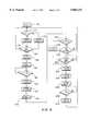
- FIG. 6is a block diagram of suitable logic for controlling the dosage of cellulose according to the present invention.
- FIG. 7illustrates a graph of the automatic search for powder dosage rate as a function of time according to this invention.
- FIG. 8is an alternative graph of the powder dosage rate as a function of time when a pressure high limit is reached at the well head.
- FIG. 1schematically illustrates one embodiment of an equipment assembly according to the present invention for performing a water flooding operation to recover oil from a partially depleted, low pressure production field.
- the assembly 10is portable, so that the equipment may be easily transported from one injection well to another, and/or from a production field to another, thereby reducing overall equipment costs.
- the primary components of the assembly 10are mounted on one of four trailers: a pumping/utilities trailer 12, a cellulose mixing and control trailer 14, a power generator/utilities trailer 16, and a bulk trailer 18.
- Each trailermay be a conventional transport trailer which accordingly may be easily positioned at a desired location about the production field.
- the water flooding operationutilises an available water source, which may be output from a site water supply WS pipeline.
- the assembly 10mixes the water with a cellulose powder, and injects the mixture down one of a plurality of selectively positioned injection wells U, so that more oil may be recovered from the production field.
- oilmay be simultaneously recovered from one or more of a plurality of production wells (not shown) spaced about the field.
- Recovered water from supply WSmay be pressurized by suitable equipment not depicted in FIG. 1.
- Pressurized water used for injectionis first pressure-regulated by choke valve 31, which is automatically responsive to the level control device 36 provided on mixing tank 35 to maintain the desired water level in the mixing tank.
- the waterBefore being passed to tank 35, the water preferably is filtered to reduce equipment wear and damage to the formation, and suitable hydrocyclone filters 32 are thus provided between the choke valve 31 and the mixing tank 35. Waste skip 67 may also be provided on trailer 14 for storage of the discharge from the filters 32.
- a high delivery control valve 33 and a low delivery control valve 34are provided in parallel between the filters 32 and the tank 35, and the operator may control each valve as a function of the desired injection water flowrate to create a vortex in the mixing tank 35.
- the operatortherefore determines a desired injection flowrate into an injection well utilizing conventional techniques, and then regulates the control valves to achieve that desired flowrate. Since the quantity of dosing material added is relatively small, the desired or optional injection flowrate is, for practical purposes, the desired or optimal water flowrate to the mixing tank.
- the cellulose/water mixture from the mixing tank 35passes through flowmeter 44, and then to pumping trailer 12, where the mixture is pressurized to a selected pressure by one or two injection pumps 45 mounted in parallel on the trailer 12.
- the mixtureis then transmitted through a series of conventional valves to a selected injection well 13 as shown in FIG. 1.
- the mixtureis injected into the formation and is pushed in the direction of the production wells with the injected water serving to entrain the oil in the formation and carry it toward the production wells.
- the celluloseis dispersed in the water at a desired rate within the mixing tank 35, but hydration is delayed due to the mixing process.
- Each injection pump 45is driven by a variable speed motor 78 so that the desired injection flowrate for an individual well may be achieved by controlling the speed of the pumps 45.
- Each of the main pumps 45may thus be powered by a double wound motor 78, so that each pump may operate at two different pump speeds.
- each pump 45may operate at a continuously variable speed if a variable speed drive motor is utilised.
- the bulk trailer 18includes a conventional tanker 51 for housing cellulose powder.
- Compressed air from the generator trailer 16pressurizes the tanker 51 to a desired pressure level, e.g., slightly greater than ambient pressure.
- Transmitters 52may be provided for monitoring the level of powder within the tanker 51.
- the pressure regulator 64 and a flow control orifice or flow choke 63 on the trailer 14may thus be adjusted to set the air pressure in the tanker 51 at a desired level.
- the fluid pressure within the tankermay be monitored by pressure transmitter 53.
- Nitrogen bottles 85may be provided on the bulk trailer 18 for subjecting the powder in the tanker 51 to inert gas when the powder is not being delivered to the hopper 42.
- one of the product valves 55is opened to deliver powder from the tanker 51 through the flexible line 95 to the feed hopper 42.
- Blowdown control valves 59 and 62may be used to adjust the pressure in the flexible line 95. Flow control of the regulated air may also be set by a suitable nozzle 97 to provide a consistent blow of air pressure higher than that present in the tanker 51. Fluidizing pads 54 on the tanker 51 keep fine powder flowing to the production valves 55.
- production valves 55may be closed and only pressurized air blown down the transfer line 95.
- the powder control valves 60 and 61are opened to start the air flow down the transfer line 95.
- predetermined period of timee.g., two seconds
- product valves 55are opened. Powder is then supplied to the hopper 42 until the high level switch 41 is covered with powder, (or alternatively after a preselected time period has expired), at which time the product valves 55 are closed and the transfer line 95 cleaned with pressurized air.
- the desired dosage rate of powderis supplied to the tank 35 from the hopper 42 by the screw conveyor 39 and the vibrating table 37 simplistically shown in FIG. 1.
- the variable speed screw conveyor 39is calibrated for supplying powder to the mixing tank at a desired dosing rate.
- the mixing tank 35includes two angled water inlets, with each inlet being in fluid communication with one of the valves 33 and 34 to create a vortex within the mixing tank. Either or both of the valves 33 and 34 may be opened by the operator, depending on desired water flowrate to the mixing tank and thus to the injection well. Cellulose powder from the vibrating table 37 may be added to the center of the vortex to ensure that the powder is evenly mixed with the water. The powder remains for a substantially uniform and short duration time within the mixing tank 35 before being discharged to the pumps 45.
- a control panel 66 on the trailer 14includes a primary or supervisory/control computer 82, a personal computer 84 with a data entry keyboard, and an audible or visual alarm 86.
- Computer 82receives a flowrate signal from the flowmeter 44, and transmits a powder flowrate signal to the variable speed screw conveyor 39 to supply powder to the mixing tank 35 at the desired dosage rate.
- the desired dosage rate signalmay be expressed as a function of a dosing percentage rate multiplied by the flowrate signal from the flowmeter 44, then divided by a constant that is derived from the calibration for the particular product in use, to yield the powder flowrate signal which controls the revolutions of the conveyor 39 to supply the desired quantity of powder to be mixed with the injection water.
- a tacho feedback loop 38is provided to ensure that the correct conveyor speed is achieved.
- the computer 82 and the tacho 38thus regulate the rare that powder added to the injection water, and monitor the powder addition rate and the actual conveyor speed to provide the proper dosage rate.
- the air space 94 above the water in the mixing tank 35is preferably pressurized with nitrogen or another inert gas to ensure that moisture is suppressed from rising, since the premature combination of moisture and the powder adversely affect the operation of the system.
- a nitrogen blanket in the space 94also ensures that oxygen is not entrained in the injection water/powder mixture, thereby minimizing corrosion of the tubular strings in the injection well and production wells, as well as damage to the formation and formation fluids.
- Nitrogenmay be supplied to the tank 35 from bottles 43 mounted on the trailer 14.
- the water level in the mixing tank 35is thus regulated by choke valve 31, which in turn is controlled by a dedicated choke valve controller 96.
- controller 96receives a signal from the mixing tank level transmitter 36, and compares the transmitter signal with a requested mixing tank level signal input to the controller by the computer 82.
- Two diesel generators 75 and 76are mounted on the trailer 16 for generating electrical power, with each generator being fueled by diesel tank 71.
- a diesel transport unit 80is provided for intermittently filling the tank 71.
- the generator 75may be a 15 kilowatt air-cooled generator for supplying single phase 220 volt A.C. power, while the generator 76 is a 395 kilowatt water-cooled generator for supplying both three phase 380 volt and single phase 220 volt power.
- the generator 76 temperatureshould be above -10° C. before it is started, and accordingly the generator 75 may be initially started at a colder temperature, and the power from the generator 75 used to heat the oil sump of generator 76 before the generator 76 is started.
- Generator control panel 73is mounted on the trailer 16, and includes a computer 88, pump controls 90, and motor controls 92.
- Generators 75 and 76thus supply electrical power to emergency batteries 74, which also serve as a D.C. power supply.
- the pump motors 78, and other motors (not shown) which may be provided on any one of the trailers,are thus powered by the generators.
- a transformer 98may be used to charge emergency batteries 74.
- Three phase, 380 volt poweris thus available for driving the motors 78, and the motor (not shown) which powers the air compressor 56 which pressurizes receiver or tank 57.
- Single phase, 220 volt powermay be used for pump control logic for driving the motors for the screw conveyor 39, and for powering a D.C. power supply or batteries 74. Power from the 24 volt D.C. supply may be used for logic control, and for powering the computers.
- the generator trailer 16may also include conventional power and engine monitoring equipment, as well as automatic shut-down equipment.
- Water flushing tank 46provided on the pumping trailer provides a water supply source in case of loss of the supply from the anticipated water source, and provides water for clean-down of the injection well and for clean down of the equipment before relocation of the equipment.
- Flush pump 47is controlled by the offload control valves 107 on the trailer 12.
- an automatic off-loading systemis also provided.
- the equipment shown in FIG. 1is designed to reduce the likelihood of powder mixing with water prior to being intentionally mixed in the mixing tank 35, so that mixture will set at its desired location within the porous formation, and will not set prematurely.
- the assembly as shown in FIG. 1is, however, also constructed for quick disassembly, so that blockages caused by premature setting may be easily cleared and the system properly maintained.
- Control panel 114generates the dosage signal 122 to the screw conveyor motor 116, with the signal 122 being a function of the Qhr signal 120 and the flowrate signal 130.
- the signal 122thus serves to control the operation of the motor 116 at the desired speed.
- the screw conveyor tacho 38 in FIG. 1generates a feed back loop signal 124 to the control panel 114 to ensure that the conveyor is operating at its proper speed.
- the speed or the conveyor motor 116is also input as signal 126 to the computer 112 to serve as a check on the proper determination of the dosing rate.
- Computer 112may activate an alarm (see 86 in FIG. 1) if the actual speed of the motor 116 does not correspond, within a selected range, to the desired dosage rate of powder to the mixing tank 35.
- FIG. 3illustrates suitable logic 140 for controlling the flow of water to the mixing tank 35.
- a tank level signal 156is transmitted from the transmitter 36 to the choke valve controller 96, and a similar signal 158 is transmitted to computer 146, which functionally may be the computer 82 shown in FIG. 1.
- the controller 96outputs a control signal 150 to the choke valve 31 to regulate the fluid flowrate to the mixing tank.
- the choke valve 31includes a valve position indicator 142, which transmits a valve position signal 152 to the controller 96 to monitor the actual choke position and ensure that the valve is properly positioned by the controller.
- This same valve position signalmay be transmitted as signal 154 to the computer 146, so that the computer 146 may compare the signals 158 and 154, and then generate a requested tank level signal 160 to the controller 96.
- Controller 96receives signal 156 from the level transmitter 36 and compares this signal with the requested mixing tank level input signal 160 from the computer 146.
- the output signal 150 from the controller 96is effectively transmitted as the choke position signal 154 back to the computer 146, so that computer 146 effectively receives both the tank level signal and the choke valve control signal to provide monitoring and alarm functions.
- FIG. 4illustrates suitable control logic 170 for transferring powder from the tanker 51 to the hopper 42.
- the operationis initiated with at start step 172, and comparator 174 initially determines that the pressure P in the tanker is less than the preset value, which may be selected to be 1.1 Barg. If the tanker pressure is more than 1.1 Barg, step 174 first closes the tanker pressurization valve 61 as shown in FIG. 1 at step 178. If the tank pressure is less than the set 1.1 Barg value, operation step 176 opens the pressurization valve. Decision step 180 then determines if the low level switch 40 on the hopper 42 is sets and if set, the blowdown values 59 and 62 as shown in FIG. 1 are opened by step 182.
- Step 184starts timer A, and comparator 186 determines if timer A exceeds a selected value, X, which selected value representatively may be 2 seconds. Once the time is greater than 2 seconds, the tanker pressurization valve 61 and the product valve 55 are opened by steps 188 and 190, respectively. A second timer B may then be started by step 192, and comparator 194 used to determine if the time set by timer B is greater than a selected number of seconds, X, if the time is greater than X, an alarm is sounded by step 198. Assuming, however, that the time is less than X, decision step 196 determines if the switch 40 has been reset.
- Xwhich selected value representatively may be 2 seconds.
- decision step 200determines if the high level switch 41 has been set. Once that product control valve 55 is closed by step 202, then the tanker pressurization valve 61 is closed by sites 204. Step 206 starts a third timer C, and comparator 208 determines if time is greater than a selected time, X. Assuming the proper time has transpired, blowdown line values 59 and 62 are closed by step 210.
- a suitable logic diagram 220 for controlling the injection pumps 45is depicted in FIG. 5.
- Step 222generates a start pump request signal, and decision step 224 determines if the interlock flag is properly set. If the interlock flag is not set, step 226 sets the interlock flag.
- Step 228opens the air valves 58 which will supply air to open the offloading valves 48.
- Decision step 130determines that the offloading valves have been properly opened, then step 232 starts one of the pumps 45 in the star configuration, with timer A then starting as shown in step 234.
- Comparator 236determines that time is above a selected value, X. Once time is greater than X, step 238 stops and resets the timer A.
- Operation step 240switches the motor 45 to the delta configuration, and the offloading valves are closed by step 242.
- the interlock flagis reset by step 244.
- Decision step 246checks that the stop pump request signal is not active.
- step 248opens the off loading valve and another timer B is started by step 250.
- step 248opens the offloading valves, and another timer B is started by step 250.
- Step 252ensures that the offloading valves are opened and, if not opened, comparator 254 determines whether the elapsed time is greater than X.
- Step 256stops and resets the timer B, and the pumps 45 are stopped by step 258.
- FIG. 6depicts the control logic 260 for controlling the powder dosage rate according to the present invention.
- the main program loopstarts at step 262, where the program waits for a start signal.
- the start signalinitializes the program variables at step 264.
- Flow totalizationis initiated at step 266, and a start task signal is initiated by 168.
- Step 270ensures that the totalization is set to 0.
- the comparator 272determines that the injection water flowrate signal is not less than a selected value, F.
- Comparator 274determines that the totalized flow is less than a selected value, e.g., 15 cubic meters, and decision step 282 determines that the cycle count is less than 1.
- comparator 278determines whether the pressure is less than a preselected value and, if not, the flag is set at step 276. If the pressure is greater than the preselected value, step 280 determines if the initial dosing rate has been set. If the dosing rate has not been set, step 288 sets the dosing rate, step 290 sets Qstol to 0, and comparator 292 determines that the flowrate is less than a selected value. Comparator 294 similarly determines if the totalized flow is less than 15 cubic meters. Step 296 checks the dosage rate, and comparator 298 determines if the dosage rate is greater than a selected value. The dosage rate may be restored to a lower value by step 300.
- Comparator 316ensures that the annulus pressure Pa is less than the selected maximum pressure, Pm, and also ensures that the injection tubing pressure Pt is less than its respective preselected value. Assuming both pressures are less than their maximum values, comparator 318 checks whether the total weight of the added dosage powder is less than the set maximum dosage weight. Once all the dosage powder has been added to the mixer 35, dosage is stopped at step 330, and the selected dosage variables are set to 0 at step 332. At step 334, the totalized mixture flow is checked to be sure that it is greater than a selected value, e.g., 30 cubic meters and, if so, step 336 signals that the process is complete. If the elapsed time at step 308 is greater than 4 hours, the cycle counter is set to 0 at step 310, and the time is set to 0 at step 314 and stopped.
- a selected valuee.g. 30 cubic meters
- the injection well annulus pressure and tubing pressuresare checked. If the monitor pressures exceed their respective preselected values, the set dosage rate is checked at step 342. Step 344 reduces the dosing rate by a selected value, e.g. 0.1%. At step 346, the minimum dosage rate is set to Qhr, and at step 348 the maximum dosing rate may be set at 1.0%. At step 350, all dosage is stopped. At step 352, the cycle count is incremented, and step 354 checks the cycle count. If the cycle count is greater than 4, the flag is set at step 356 to indicate the abnormal end of dosage, with the pump being stopped at step 358. The pump may also be stopped in response to decision step 284, which checks the pressures Pa and Pt previously discussed. If the pressures are too high, the alarm is activated at step 286, and the pump stopped at step 358.
- a selected valuee.g. 0.1%.
- the minimum dosage rateis set to Qhr, and at step 348 the maximum dosing rate may be set at 1.0%
- a maximum dosing rate of 2.3% powder to fluid injection watermay be set. Powder is initially dosed at a 0.1 percent rate, and assuming that he monitored pressure from the transmitters 49 and 50 have not been exceeded, the dosing rate is increased by 0.1 percent, as shown by the stepped line portion 412 in FIG. 7. If the maximum annulus pressure is reached, the maximum dosage rate should be reduced (see line 414), and the addition of powder is stopped, as shown by line 424. The dosage rate represented by line 414 is entered into computer 82 as the rate Qhr discussed above.
- the dosage rateis again stepped up to level of line 420, with level of line 420 being less than the level of line 418 by a select amount, e.g., 0.1%. If Pa is less than Pa max, the dosage rate may then be maintained at this level. If Pa max is reached 4 times, dosage is stopped. A quantity of water, e.g., 30 cubic meters of water, is then injected, and an alarm is activated to signal the operator. It may then be possible to restart the pumps at a lower flowrate and try dosage again.
- a select amounte.g. 0.1%.
- dosingmay again be stopped and restarted at the level of line 468, which is less than the line 460 level. If this starting and stopping of the dosage operation occurs more than four times within a preset period of time, all dosage is preferably stopped and an alarm sounded to indicate that operator interaction is desire. If dosage is carried out at a stable Qhr rate for more than four hours without adjustment, the counter is reset. It is possible to try dosing again automatically with a lower flowrate. If Pa is reached, the system may thus search for a new dosage rate four times, as described before.
- the control valves 33 and 34are preferably of the type which automatically (or semiautomatically) control the desired or optimum water injection flowrate to the mixing tanks and thus the injection flowrate to a certain injection well.
- the control valves 33 and 34may be conventionally programmed or otherwise controlled to increase the flowrate of water (while simultaneously the flowrate of powder is decreased) if the pressure of the injection well rises above a set value, thereby preventing plugging or the injection well and optimizing the water flooding operation.
- cellulose ethersmay be used for plugging the established flow channels in the formation.
- a list of suitable cellulose ethersis provided in U.S. Pat. No. 3,848,673 assigned to Phillips Petroleum Company, and includes various carboxyalykl cellulose ethers, hydroxyalkyl ethers, hydroxoyalkyl celluloses, and hydroxypropylmethyl celluloses.
- the concepts of the present inventionmay also be applied to other gel forming materials, such as those discussed in U.S. Pat. No. 3,707,191.
Landscapes
- Geology (AREA)
- Life Sciences & Earth Sciences (AREA)
- Engineering & Computer Science (AREA)
- Mining & Mineral Resources (AREA)
- Environmental & Geological Engineering (AREA)
- Fluid Mechanics (AREA)
- Physics & Mathematics (AREA)
- General Life Sciences & Earth Sciences (AREA)
- Geochemistry & Mineralogy (AREA)
- Accessories For Mixers (AREA)
- Polysaccharides And Polysaccharide Derivatives (AREA)
- Pharmaceuticals Containing Other Organic And Inorganic Compounds (AREA)
- Medicinal Preparation (AREA)
- Feeding, Discharge, Calcimining, Fusing, And Gas-Generation Devices (AREA)
Abstract
Description
Claims (22)
Applications Claiming Priority (4)
| Application Number | Priority Date | Filing Date | Title |
|---|---|---|---|
| PCT/GB1993/002498WO1995016103A1 (en) | 1993-12-06 | 1993-12-06 | Cellulose injection system and method |
| CN93121147.6ACN1103700A (en) | 1993-12-06 | 1993-12-06 | Cellulose injection system |
| CA002177809ACA2177809A1 (en) | 1993-12-06 | 1993-12-06 | Cellulose injection system and method |
| OA60833AOA10720A (en) | 1993-12-06 | 1996-06-06 | Cellulose injection system and method |
Publications (1)
| Publication Number | Publication Date |
|---|---|
| US5865247Atrue US5865247A (en) | 1999-02-02 |
Family
ID=33437092
Family Applications (1)
| Application Number | Title | Priority Date | Filing Date |
|---|---|---|---|
| US08/640,801Expired - Fee RelatedUS5865247A (en) | 1993-12-06 | 1993-12-06 | Cellulose injection system and method |
Country Status (12)
| Country | Link |
|---|---|
| US (1) | US5865247A (en) |
| EP (1) | EP0728253B1 (en) |
| CN (1) | CN1103700A (en) |
| AU (1) | AU690089B2 (en) |
| BR (1) | BR9307909A (en) |
| CA (1) | CA2177809A1 (en) |
| DE (1) | DE69318734D1 (en) |
| FI (1) | FI962344A7 (en) |
| NO (1) | NO962333L (en) |
| OA (1) | OA10720A (en) |
| RU (1) | RU2146327C1 (en) |
| WO (1) | WO1995016103A1 (en) |
Cited By (54)
| Publication number | Priority date | Publication date | Assignee | Title |
|---|---|---|---|---|
| US6212948B1 (en)* | 1999-06-28 | 2001-04-10 | Donald W. Ekdahl | Apparatus and method to obtain representative samples of oil well production |
| CN100344854C (en)* | 2005-09-09 | 2007-10-24 | 万奥普(北京)石油工程技术开发研究院有限公司 | Chemical multi-component preparation and injection method and multi-component static mixing device |
| RU2342417C1 (en)* | 2007-03-21 | 2008-12-27 | Открытое акционерное общество "Научно-исследовательский институт по нефтепромысловой химии" ОАО "НИИнефтепромхим" | Method of production of reagent for increasing oil yield of formation and method of oil deposit development |
| US20090242201A1 (en)* | 2007-06-25 | 2009-10-01 | Jorgen Van Beurden | System and method for polymer distribution to well sites |
| WO2010090889A3 (en)* | 2009-02-05 | 2010-11-04 | Shell Oil Company | Polymer recovery and recycle |
| US20110220354A1 (en)* | 2008-09-17 | 2011-09-15 | Schlumberger Norge As | Polymer gels as flow improvers in water injection systems |
| CN103670355A (en)* | 2014-01-07 | 2014-03-26 | 大庆摩恩达工程有限公司 | Remote monitoring water injection-polymer injection device |
| US20140138079A1 (en)* | 2012-11-16 | 2014-05-22 | Us Well Services Llc | System for Pumping Hydraulic Fracturing Fluid Using Electric Pumps |
| CN104033140A (en)* | 2014-07-02 | 2014-09-10 | 张玉雪 | Pumping well pump lower injection agent mixing device |
| US9611728B2 (en)* | 2012-11-16 | 2017-04-04 | U.S. Well Services Llc | Cold weather package for oil field hydraulics |
| US9650871B2 (en)* | 2012-11-16 | 2017-05-16 | Us Well Services Llc | Safety indicator lights for hydraulic fracturing pumps |
| US9650879B2 (en) | 2012-11-16 | 2017-05-16 | Us Well Services Llc | Torsional coupling for electric hydraulic fracturing fluid pumps |
| US9745840B2 (en) | 2012-11-16 | 2017-08-29 | Us Well Services Llc | Electric powered pump down |
| US9840901B2 (en) | 2012-11-16 | 2017-12-12 | U.S. Well Services, LLC | Remote monitoring for hydraulic fracturing equipment |
| US9893500B2 (en) | 2012-11-16 | 2018-02-13 | U.S. Well Services, LLC | Switchgear load sharing for oil field equipment |
| US9970278B2 (en) | 2012-11-16 | 2018-05-15 | U.S. Well Services, LLC | System for centralized monitoring and control of electric powered hydraulic fracturing fleet |
| US9995218B2 (en) | 2012-11-16 | 2018-06-12 | U.S. Well Services, LLC | Turbine chilling for oil field power generation |
| US10020711B2 (en) | 2012-11-16 | 2018-07-10 | U.S. Well Services, LLC | System for fueling electric powered hydraulic fracturing equipment with multiple fuel sources |
| US10036238B2 (en) | 2012-11-16 | 2018-07-31 | U.S. Well Services, LLC | Cable management of electric powered hydraulic fracturing pump unit |
| US10119381B2 (en) | 2012-11-16 | 2018-11-06 | U.S. Well Services, LLC | System for reducing vibrations in a pressure pumping fleet |
| US10232332B2 (en) | 2012-11-16 | 2019-03-19 | U.S. Well Services, Inc. | Independent control of auger and hopper assembly in electric blender system |
| US10254732B2 (en) | 2012-11-16 | 2019-04-09 | U.S. Well Services, Inc. | Monitoring and control of proppant storage from a datavan |
| US10280724B2 (en) | 2017-07-07 | 2019-05-07 | U.S. Well Services, Inc. | Hydraulic fracturing equipment with non-hydraulic power |
| US10407990B2 (en) | 2012-11-16 | 2019-09-10 | U.S. Well Services, LLC | Slide out pump stand for hydraulic fracturing equipment |
| US10408031B2 (en) | 2017-10-13 | 2019-09-10 | U.S. Well Services, LLC | Automated fracturing system and method |
| US10526882B2 (en) | 2012-11-16 | 2020-01-07 | U.S. Well Services, LLC | Modular remote power generation and transmission for hydraulic fracturing system |
| US10598258B2 (en) | 2017-12-05 | 2020-03-24 | U.S. Well Services, LLC | Multi-plunger pumps and associated drive systems |
| US10648270B2 (en) | 2018-09-14 | 2020-05-12 | U.S. Well Services, LLC | Riser assist for wellsites |
| US10648311B2 (en) | 2017-12-05 | 2020-05-12 | U.S. Well Services, LLC | High horsepower pumping configuration for an electric hydraulic fracturing system |
| US10655435B2 (en) | 2017-10-25 | 2020-05-19 | U.S. Well Services, LLC | Smart fracturing system and method |
| US10851635B1 (en) | 2019-02-14 | 2020-12-01 | National Service Alliance—Houston LLC | Electric driven hydraulic fracking system |
| US10871045B2 (en) | 2019-02-14 | 2020-12-22 | National Service Alliance—Houston LLC | Parameter monitoring and control for an electric driven hydraulic fracking system |
| US10876358B2 (en) | 2019-02-14 | 2020-12-29 | National Service Alliance—Houston LLC | Variable frequency drive configuration for electric driven hydraulic fracking system |
| US10988998B2 (en) | 2019-02-14 | 2021-04-27 | National Service Alliance—Houston LLC | Electric driven hydraulic fracking operation |
| US10989031B2 (en) | 2019-02-14 | 2021-04-27 | National Service Alliance-Houston LLC | Power distribution trailer for an electric driven hydraulic fracking system |
| US11009162B1 (en) | 2019-12-27 | 2021-05-18 | U.S. Well Services, LLC | System and method for integrated flow supply line |
| US11035207B2 (en) | 2018-04-16 | 2021-06-15 | U.S. Well Services, LLC | Hybrid hydraulic fracturing fleet |
| US11067481B2 (en) | 2017-10-05 | 2021-07-20 | U.S. Well Services, LLC | Instrumented fracturing slurry flow system and method |
| US11114857B2 (en) | 2018-02-05 | 2021-09-07 | U.S. Well Services, LLC | Microgrid electrical load management |
| US11181107B2 (en) | 2016-12-02 | 2021-11-23 | U.S. Well Services, LLC | Constant voltage power distribution system for use with an electric hydraulic fracturing system |
| US11211801B2 (en) | 2018-06-15 | 2021-12-28 | U.S. Well Services, LLC | Integrated mobile power unit for hydraulic fracturing |
| US11208878B2 (en) | 2018-10-09 | 2021-12-28 | U.S. Well Services, LLC | Modular switchgear system and power distribution for electric oilfield equipment |
| US11408250B2 (en) | 2017-11-14 | 2022-08-09 | Halliburton Energy Services, Inc. | Adjusting the zonal allocation of an injection well with no moving parts and no intervention |
| US11421673B2 (en) | 2016-09-02 | 2022-08-23 | Halliburton Energy Services, Inc. | Hybrid drive systems for well stimulation operations |
| US11449018B2 (en) | 2012-11-16 | 2022-09-20 | U.S. Well Services, LLC | System and method for parallel power and blackout protection for electric powered hydraulic fracturing |
| US11476781B2 (en) | 2012-11-16 | 2022-10-18 | U.S. Well Services, LLC | Wireline power supply during electric powered fracturing operations |
| US11542786B2 (en) | 2019-08-01 | 2023-01-03 | U.S. Well Services, LLC | High capacity power storage system for electric hydraulic fracturing |
| US11578577B2 (en) | 2019-03-20 | 2023-02-14 | U.S. Well Services, LLC | Oversized switchgear trailer for electric hydraulic fracturing |
| US11613963B2 (en) | 2017-07-24 | 2023-03-28 | Halliburton Energy Services, Inc. | Flow control system for a non-newtonian fluid in a subterranean well |
| US11728709B2 (en) | 2019-05-13 | 2023-08-15 | U.S. Well Services, LLC | Encoderless vector control for VFD in hydraulic fracturing applications |
| US11959371B2 (en) | 2012-11-16 | 2024-04-16 | Us Well Services, Llc | Suction and discharge lines for a dual hydraulic fracturing unit |
| US12078110B2 (en) | 2015-11-20 | 2024-09-03 | Us Well Services, Llc | System for gas compression on electric hydraulic fracturing fleets |
| US12221872B2 (en) | 2014-10-14 | 2025-02-11 | U.S. Well Services, LLC | System and method for parallel power and blackout protection for electric powered hydraulic fracturing |
| US12442281B2 (en) | 2023-11-07 | 2025-10-14 | U.S. Well Services, LLC | Smart fracturing system and method |
Families Citing this family (6)
| Publication number | Priority date | Publication date | Assignee | Title |
|---|---|---|---|---|
| RU2169258C1 (en)* | 2000-11-15 | 2001-06-20 | Общество с ограниченной ответственностью "Научно-производственное предприятие "ТАТРОЙЛ" | Method of equalization of injectivity profile in injection wells and restriction of water inflows to producing wells |
| GB0416310D0 (en)* | 2004-07-21 | 2004-08-25 | Bp Exploration Operating | Method |
| US7565835B2 (en) | 2004-11-17 | 2009-07-28 | Schlumberger Technology Corporation | Method and apparatus for balanced pressure sampling |
| NO324547B1 (en)* | 2005-09-23 | 2007-11-19 | Well Proc As | Method and apparatus for chemical dosing for injection water |
| US10465490B2 (en)* | 2016-07-18 | 2019-11-05 | Eastman Chemical Company | Well treatment fiber delivery system |
| CN106917613B (en)* | 2017-04-24 | 2023-06-23 | 新疆敦华石油技术股份有限公司 | Oilfield liquid carbon dioxide injection device and injection method |
Citations (8)
| Publication number | Priority date | Publication date | Assignee | Title |
|---|---|---|---|---|
| US3707191A (en)* | 1970-05-27 | 1972-12-26 | Phillips Petroleum Co | Gel fluid water flooding method |
| US3863717A (en)* | 1973-01-16 | 1975-02-04 | Schlumberger Cie Dowell | Methods for forcing a liquid into a low pressure formation |
| US4004639A (en)* | 1976-03-17 | 1977-01-25 | Union Oil Company Of California | Selectively plugging the more permeable strata of a subterranean formation |
| US4014527A (en)* | 1973-12-20 | 1977-03-29 | Mobil Oil Corporation | Chemical blending system |
| US4374544A (en)* | 1980-09-19 | 1983-02-22 | Standard Oil Company (Indiana) | Technique for control of injection wells |
| US4395340A (en)* | 1981-07-14 | 1983-07-26 | Halliburton Company | Enhanced oil recovery methods and systems |
| US4548272A (en)* | 1982-01-07 | 1985-10-22 | Marathon Oil Company | Oil recovery process using a polymer gel |
| US5343941A (en)* | 1992-12-03 | 1994-09-06 | Raybon Michael L | Apparatus for treating oil and gas wells |
Family Cites Families (6)
| Publication number | Priority date | Publication date | Assignee | Title |
|---|---|---|---|---|
| US3472319A (en)* | 1967-06-23 | 1969-10-14 | Chevron Res | Method of improving fluid flow in porous media |
| US3848673A (en)* | 1973-02-26 | 1974-11-19 | Phillips Petroleum Co | Recovery of hydrocarbons |
| US4451389A (en)* | 1980-05-22 | 1984-05-29 | Phillips Petroleum Company | Aqueous gels |
| US4627494A (en)* | 1985-03-04 | 1986-12-09 | Texaco Inc. | Method of using a lignosulfonate/carbohydrate system as a sacrificial agent for surfactant flooding |
| US4953618A (en)* | 1989-01-12 | 1990-09-04 | Haliburton Company | Injection manifold and method |
| SU1755611A1 (en)* | 1990-06-25 | 1996-06-10 | Научно-производственное объединение по химизации технологических процессов в нефтяной промышленности | Method for development of nonuniform oil formation |
- 1993
- 1993-12-06RURU96115004Apatent/RU2146327C1/enactive
- 1993-12-06DEDE69318734Tpatent/DE69318734D1/ennot_activeExpired - Lifetime
- 1993-12-06USUS08/640,801patent/US5865247A/ennot_activeExpired - Fee Related
- 1993-12-06CACA002177809Apatent/CA2177809A1/ennot_activeAbandoned
- 1993-12-06AUAU56551/94Apatent/AU690089B2/ennot_activeExpired - Fee Related
- 1993-12-06BRBR9307909Apatent/BR9307909A/ennot_activeApplication Discontinuation
- 1993-12-06EPEP94902036Apatent/EP0728253B1/ennot_activeExpired - Lifetime
- 1993-12-06WOPCT/GB1993/002498patent/WO1995016103A1/enactiveIP Right Grant
- 1993-12-06CNCN93121147.6Apatent/CN1103700A/enactivePending
- 1996
- 1996-06-05FIFI962344Apatent/FI962344A7/ennot_activeApplication Discontinuation
- 1996-06-05NONO962333Apatent/NO962333L/enunknown
- 1996-06-06OAOA60833Apatent/OA10720A/enunknown
Patent Citations (8)
| Publication number | Priority date | Publication date | Assignee | Title |
|---|---|---|---|---|
| US3707191A (en)* | 1970-05-27 | 1972-12-26 | Phillips Petroleum Co | Gel fluid water flooding method |
| US3863717A (en)* | 1973-01-16 | 1975-02-04 | Schlumberger Cie Dowell | Methods for forcing a liquid into a low pressure formation |
| US4014527A (en)* | 1973-12-20 | 1977-03-29 | Mobil Oil Corporation | Chemical blending system |
| US4004639A (en)* | 1976-03-17 | 1977-01-25 | Union Oil Company Of California | Selectively plugging the more permeable strata of a subterranean formation |
| US4374544A (en)* | 1980-09-19 | 1983-02-22 | Standard Oil Company (Indiana) | Technique for control of injection wells |
| US4395340A (en)* | 1981-07-14 | 1983-07-26 | Halliburton Company | Enhanced oil recovery methods and systems |
| US4548272A (en)* | 1982-01-07 | 1985-10-22 | Marathon Oil Company | Oil recovery process using a polymer gel |
| US5343941A (en)* | 1992-12-03 | 1994-09-06 | Raybon Michael L | Apparatus for treating oil and gas wells |
Cited By (124)
| Publication number | Priority date | Publication date | Assignee | Title |
|---|---|---|---|---|
| US6499344B2 (en) | 1999-06-28 | 2002-12-31 | Donald C. Nelson | Apparatus and method to obtain representative samples of oil well production |
| US6212948B1 (en)* | 1999-06-28 | 2001-04-10 | Donald W. Ekdahl | Apparatus and method to obtain representative samples of oil well production |
| CN100344854C (en)* | 2005-09-09 | 2007-10-24 | 万奥普(北京)石油工程技术开发研究院有限公司 | Chemical multi-component preparation and injection method and multi-component static mixing device |
| RU2342417C1 (en)* | 2007-03-21 | 2008-12-27 | Открытое акционерное общество "Научно-исследовательский институт по нефтепромысловой химии" ОАО "НИИнефтепромхим" | Method of production of reagent for increasing oil yield of formation and method of oil deposit development |
| US20090242201A1 (en)* | 2007-06-25 | 2009-10-01 | Jorgen Van Beurden | System and method for polymer distribution to well sites |
| US20110220354A1 (en)* | 2008-09-17 | 2011-09-15 | Schlumberger Norge As | Polymer gels as flow improvers in water injection systems |
| US9903169B2 (en)* | 2008-09-17 | 2018-02-27 | Schlumberger Norge As | Polymer gels as flow improvers in water injection systems |
| GB2478891B (en)* | 2009-02-05 | 2014-09-17 | Shell Int Research | Polymer recovery and recycle |
| WO2010090889A3 (en)* | 2009-02-05 | 2010-11-04 | Shell Oil Company | Polymer recovery and recycle |
| GB2478891A (en)* | 2009-02-05 | 2011-09-21 | Shell Int Research | Polymer recovery and recycle |
| CN102307814B (en)* | 2009-02-05 | 2013-10-30 | 国际壳牌研究有限公司 | Polymer recovery and recycling |
| US10731561B2 (en) | 2012-11-16 | 2020-08-04 | U.S. Well Services, LLC | Turbine chilling for oil field power generation |
| US10934824B2 (en) | 2012-11-16 | 2021-03-02 | U.S. Well Services, LLC | System for reducing vibrations in a pressure pumping fleet |
| US11674352B2 (en) | 2012-11-16 | 2023-06-13 | U.S. Well Services, LLC | Slide out pump stand for hydraulic fracturing equipment |
| US9410410B2 (en)* | 2012-11-16 | 2016-08-09 | Us Well Services Llc | System for pumping hydraulic fracturing fluid using electric pumps |
| US9611728B2 (en)* | 2012-11-16 | 2017-04-04 | U.S. Well Services Llc | Cold weather package for oil field hydraulics |
| US9650871B2 (en)* | 2012-11-16 | 2017-05-16 | Us Well Services Llc | Safety indicator lights for hydraulic fracturing pumps |
| US9650879B2 (en) | 2012-11-16 | 2017-05-16 | Us Well Services Llc | Torsional coupling for electric hydraulic fracturing fluid pumps |
| US9745840B2 (en) | 2012-11-16 | 2017-08-29 | Us Well Services Llc | Electric powered pump down |
| US9840901B2 (en) | 2012-11-16 | 2017-12-12 | U.S. Well Services, LLC | Remote monitoring for hydraulic fracturing equipment |
| US9893500B2 (en) | 2012-11-16 | 2018-02-13 | U.S. Well Services, LLC | Switchgear load sharing for oil field equipment |
| US20140138079A1 (en)* | 2012-11-16 | 2014-05-22 | Us Well Services Llc | System for Pumping Hydraulic Fracturing Fluid Using Electric Pumps |
| US9970278B2 (en) | 2012-11-16 | 2018-05-15 | U.S. Well Services, LLC | System for centralized monitoring and control of electric powered hydraulic fracturing fleet |
| US9995218B2 (en) | 2012-11-16 | 2018-06-12 | U.S. Well Services, LLC | Turbine chilling for oil field power generation |
| US10020711B2 (en) | 2012-11-16 | 2018-07-10 | U.S. Well Services, LLC | System for fueling electric powered hydraulic fracturing equipment with multiple fuel sources |
| US10036238B2 (en) | 2012-11-16 | 2018-07-31 | U.S. Well Services, LLC | Cable management of electric powered hydraulic fracturing pump unit |
| US10107086B2 (en) | 2012-11-16 | 2018-10-23 | U.S. Well Services, LLC | Remote monitoring for hydraulic fracturing equipment |
| US10119381B2 (en) | 2012-11-16 | 2018-11-06 | U.S. Well Services, LLC | System for reducing vibrations in a pressure pumping fleet |
| US10232332B2 (en) | 2012-11-16 | 2019-03-19 | U.S. Well Services, Inc. | Independent control of auger and hopper assembly in electric blender system |
| US10254732B2 (en) | 2012-11-16 | 2019-04-09 | U.S. Well Services, Inc. | Monitoring and control of proppant storage from a datavan |
| US11713661B2 (en) | 2012-11-16 | 2023-08-01 | U.S. Well Services, LLC | Electric powered pump down |
| US10337308B2 (en) | 2012-11-16 | 2019-07-02 | U.S. Well Services, Inc. | System for pumping hydraulic fracturing fluid using electric pumps |
| US10408030B2 (en) | 2012-11-16 | 2019-09-10 | U.S. Well Services, LLC | Electric powered pump down |
| US10407990B2 (en) | 2012-11-16 | 2019-09-10 | U.S. Well Services, LLC | Slide out pump stand for hydraulic fracturing equipment |
| US11476781B2 (en) | 2012-11-16 | 2022-10-18 | U.S. Well Services, LLC | Wireline power supply during electric powered fracturing operations |
| US10526882B2 (en) | 2012-11-16 | 2020-01-07 | U.S. Well Services, LLC | Modular remote power generation and transmission for hydraulic fracturing system |
| US11850563B2 (en) | 2012-11-16 | 2023-12-26 | U.S. Well Services, LLC | Independent control of auger and hopper assembly in electric blender system |
| US11449018B2 (en) | 2012-11-16 | 2022-09-20 | U.S. Well Services, LLC | System and method for parallel power and blackout protection for electric powered hydraulic fracturing |
| US11959371B2 (en) | 2012-11-16 | 2024-04-16 | Us Well Services, Llc | Suction and discharge lines for a dual hydraulic fracturing unit |
| US11181879B2 (en) | 2012-11-16 | 2021-11-23 | U.S. Well Services, LLC | Monitoring and control of proppant storage from a datavan |
| US10686301B2 (en) | 2012-11-16 | 2020-06-16 | U.S. Well Services, LLC | Switchgear load sharing for oil field equipment |
| US11136870B2 (en) | 2012-11-16 | 2021-10-05 | U.S. Well Services, LLC | System for pumping hydraulic fracturing fluid using electric pumps |
| US12438480B2 (en) | 2012-11-16 | 2025-10-07 | U.S. Well Services, LLC | Wireline power supply during electric powered fracturing operations |
| US12404756B2 (en) | 2012-11-16 | 2025-09-02 | U.S. Well Services, LLC | Torsional coupling for electric hydraulic fracturing fluid pumps |
| US11091992B2 (en) | 2012-11-16 | 2021-08-17 | U.S. Well Services, LLC | System for centralized monitoring and control of electric powered hydraulic fracturing fleet |
| US10927802B2 (en) | 2012-11-16 | 2021-02-23 | U.S. Well Services, LLC | System for fueling electric powered hydraulic fracturing equipment with multiple fuel sources |
| US11066912B2 (en) | 2012-11-16 | 2021-07-20 | U.S. Well Services, LLC | Torsional coupling for electric hydraulic fracturing fluid pumps |
| US10947829B2 (en) | 2012-11-16 | 2021-03-16 | U.S. Well Services, LLC | Cable management of electric powered hydraulic fracturing pump unit |
| US12209490B2 (en) | 2012-11-16 | 2025-01-28 | U.S. Well Services, LLC | System for pumping hydraulic fracturing fluid using electric pumps |
| US12228023B2 (en) | 2012-11-16 | 2025-02-18 | U.S. Well Services, LLC | Cable management of electric powered hydraulic fracturing pump unit |
| US20250084744A1 (en)* | 2012-11-16 | 2025-03-13 | U.S. Well Services, LLC | Suction and discharge lines for a dual hydraulic fracturing unit |
| CN103670355B (en)* | 2014-01-07 | 2016-07-13 | 哈尔滨鼎智瑞光科技有限公司 | Remotely monitor water injection-polymer injection |
| CN103670355A (en)* | 2014-01-07 | 2014-03-26 | 大庆摩恩达工程有限公司 | Remote monitoring water injection-polymer injection device |
| CN104033140A (en)* | 2014-07-02 | 2014-09-10 | 张玉雪 | Pumping well pump lower injection agent mixing device |
| US12221872B2 (en) | 2014-10-14 | 2025-02-11 | U.S. Well Services, LLC | System and method for parallel power and blackout protection for electric powered hydraulic fracturing |
| US12085017B2 (en) | 2015-11-20 | 2024-09-10 | Us Well Services, Llc | System for gas compression on electric hydraulic fracturing fleets |
| US12078110B2 (en) | 2015-11-20 | 2024-09-03 | Us Well Services, Llc | System for gas compression on electric hydraulic fracturing fleets |
| US12404759B2 (en) | 2016-09-02 | 2025-09-02 | Halliburton Energy Services, Inc. | Hybrid drive systems for well stimulation operations |
| US11421673B2 (en) | 2016-09-02 | 2022-08-23 | Halliburton Energy Services, Inc. | Hybrid drive systems for well stimulation operations |
| US11808127B2 (en) | 2016-09-02 | 2023-11-07 | Halliburton Energy Services, Inc. | Hybrid drive systems for well stimulation operations |
| US12110773B2 (en) | 2016-09-02 | 2024-10-08 | Halliburton Energy Services, Inc. | Hybrid drive systems for well stimulation operations |
| US11913316B2 (en) | 2016-09-02 | 2024-02-27 | Halliburton Energy Services, Inc. | Hybrid drive systems for well stimulation operations |
| US11181107B2 (en) | 2016-12-02 | 2021-11-23 | U.S. Well Services, LLC | Constant voltage power distribution system for use with an electric hydraulic fracturing system |
| US12092095B2 (en) | 2016-12-02 | 2024-09-17 | Us Well Services, Llc | Constant voltage power distribution system for use with an electric hydraulic fracturing system |
| US10280724B2 (en) | 2017-07-07 | 2019-05-07 | U.S. Well Services, Inc. | Hydraulic fracturing equipment with non-hydraulic power |
| US11613963B2 (en) | 2017-07-24 | 2023-03-28 | Halliburton Energy Services, Inc. | Flow control system for a non-newtonian fluid in a subterranean well |
| US11067481B2 (en) | 2017-10-05 | 2021-07-20 | U.S. Well Services, LLC | Instrumented fracturing slurry flow system and method |
| US11203924B2 (en) | 2017-10-13 | 2021-12-21 | U.S. Well Services, LLC | Automated fracturing system and method |
| US10408031B2 (en) | 2017-10-13 | 2019-09-10 | U.S. Well Services, LLC | Automated fracturing system and method |
| US10655435B2 (en) | 2017-10-25 | 2020-05-19 | U.S. Well Services, LLC | Smart fracturing system and method |
| US11408250B2 (en) | 2017-11-14 | 2022-08-09 | Halliburton Energy Services, Inc. | Adjusting the zonal allocation of an injection well with no moving parts and no intervention |
| US10648311B2 (en) | 2017-12-05 | 2020-05-12 | U.S. Well Services, LLC | High horsepower pumping configuration for an electric hydraulic fracturing system |
| US11959533B2 (en) | 2017-12-05 | 2024-04-16 | U.S. Well Services Holdings, Llc | Multi-plunger pumps and associated drive systems |
| US10598258B2 (en) | 2017-12-05 | 2020-03-24 | U.S. Well Services, LLC | Multi-plunger pumps and associated drive systems |
| US11114857B2 (en) | 2018-02-05 | 2021-09-07 | U.S. Well Services, LLC | Microgrid electrical load management |
| US12392232B2 (en) | 2018-02-05 | 2025-08-19 | U.S. Well Services, LLC | Microgrid electrical load management |
| US12378865B2 (en) | 2018-04-16 | 2025-08-05 | U.S. Well Services, LLC | Hybrid hydraulic fracturing fleet |
| US11035207B2 (en) | 2018-04-16 | 2021-06-15 | U.S. Well Services, LLC | Hybrid hydraulic fracturing fleet |
| US11211801B2 (en) | 2018-06-15 | 2021-12-28 | U.S. Well Services, LLC | Integrated mobile power unit for hydraulic fracturing |
| US12142928B2 (en) | 2018-06-15 | 2024-11-12 | U.S. Well Services, LLC | Integrated mobile power unit for hydraulic fracturing |
| US10648270B2 (en) | 2018-09-14 | 2020-05-12 | U.S. Well Services, LLC | Riser assist for wellsites |
| US11208878B2 (en) | 2018-10-09 | 2021-12-28 | U.S. Well Services, LLC | Modular switchgear system and power distribution for electric oilfield equipment |
| US11156044B2 (en)* | 2019-02-14 | 2021-10-26 | National Service Alliance—Houston LLC | Parameter monitoring and control for an electric driven hydraulic fracking system |
| US12006807B2 (en) | 2019-02-14 | 2024-06-11 | Halliburton Energy Services, Inc. | Power distribution trailer for an electric driven hydraulic fracking system |
| US11560764B2 (en) | 2019-02-14 | 2023-01-24 | National Service Alliance—Houston LLC | Electric driven hydraulic fracking operation |
| US11668144B2 (en) | 2019-02-14 | 2023-06-06 | National Service Alliance—Houston LLC | Variable frequency drive configuration for electric driven hydraulic fracking system |
| US10851635B1 (en) | 2019-02-14 | 2020-12-01 | National Service Alliance—Houston LLC | Electric driven hydraulic fracking system |
| US11708733B2 (en) | 2019-02-14 | 2023-07-25 | National Service Alliance—Houston LLC | Parameter monitoring and control for an electric driven hydraulic fracking system |
| US11492860B2 (en) | 2019-02-14 | 2022-11-08 | National Service Alliance—Houston LLC | Variable frequency drive configuration for electric driven hydraulic fracking system |
| US10871045B2 (en) | 2019-02-14 | 2020-12-22 | National Service Alliance—Houston LLC | Parameter monitoring and control for an electric driven hydraulic fracking system |
| US11739602B2 (en) | 2019-02-14 | 2023-08-29 | National Service Alliance—Houston LLC | Electric driven hydraulic fracking operation |
| US11773664B1 (en) | 2019-02-14 | 2023-10-03 | National Service Alliance—Houston LLC | Variable frequency drive configuration for electric driven hydraulic fracking system |
| US11788396B2 (en) | 2019-02-14 | 2023-10-17 | National Service Alliance—Houston LLC | Electric driven hydraulic fracking system |
| US11795800B2 (en) | 2019-02-14 | 2023-10-24 | National Service Alliance—Houston LLC | Power distribution trailer for an electric driven hydraulic fracking system |
| US11473381B2 (en) | 2019-02-14 | 2022-10-18 | National Service Alliance—Houston LLC | Parameter monitoring and control for an electric driven hydraulic fracking system |
| US11466550B2 (en) | 2019-02-14 | 2022-10-11 | National Service Alliance—Houston LLC | Power distribution trailer for an electric driven hydraulic fracking system |
| US11434709B2 (en) | 2019-02-14 | 2022-09-06 | National Service Alliance—Houston LLC | Electric driven hydraulic fracking operation |
| US11939828B2 (en) | 2019-02-14 | 2024-03-26 | Halliburton Energy Services, Inc. | Variable frequency drive configuration for electric driven hydraulic fracking system |
| US11319762B2 (en) | 2019-02-14 | 2022-05-03 | National Service Alliance—Houston LLC | Variable frequency drive configuration for electric driven hydraulic fracking system |
| US11286736B2 (en) | 2019-02-14 | 2022-03-29 | National Service Alliance—Houston LLC | Parameter monitoring and control for an electric driven hydraulic fracking system |
| US11976525B2 (en) | 2019-02-14 | 2024-05-07 | Halliburton Energy Services, Inc. | Electric driven hydraulic fracking operation |
| US11976524B2 (en) | 2019-02-14 | 2024-05-07 | Halliburton Energy Services, Inc. | Parameter monitoring and control for an electric driven hydraulic fracking system |
| US12000256B2 (en) | 2019-02-14 | 2024-06-04 | Halliburton Energy Services, Inc. | Electric driven hydraulic fracking system |
| US10876358B2 (en) | 2019-02-14 | 2020-12-29 | National Service Alliance—Houston LLC | Variable frequency drive configuration for electric driven hydraulic fracking system |
| US11274512B2 (en) | 2019-02-14 | 2022-03-15 | National Service Alliance—Houston LLC | Electric driven hydraulic fracking operation |
| US11220896B2 (en) | 2019-02-14 | 2022-01-11 | National Service Alliance—Houston LLC | Electric driven hydraulic fracking system |
| US11168556B2 (en) | 2019-02-14 | 2021-11-09 | National Service Alliance—Houston LLC | Power distribution trailer for an electric driven hydraulic fracking system |
| US11142972B1 (en) | 2019-02-14 | 2021-10-12 | National Service Alliance—Houston LLC | Electric driven hydraulic fracking operation |
| US11125034B2 (en) | 2019-02-14 | 2021-09-21 | National Service Alliance—Houston LLC | Variable frequency drive configuration for electric driven hydraulic fracking system |
| US10975641B1 (en) | 2019-02-14 | 2021-04-13 | National Service Alliance—Houston LLC | Variable frequency drive configuration for electric driven hydraulic fracking system |
| US11053758B2 (en) | 2019-02-14 | 2021-07-06 | National Service Alliance—Houston LLC | Electric driven hydraulic fracking system |
| US12385336B2 (en) | 2019-02-14 | 2025-08-12 | Halliburton Energy Services, Inc. | Parameter monitoring and control for an electric driven hydraulic fracking system |
| US10989031B2 (en) | 2019-02-14 | 2021-04-27 | National Service Alliance-Houston LLC | Power distribution trailer for an electric driven hydraulic fracking system |
| US10988998B2 (en) | 2019-02-14 | 2021-04-27 | National Service Alliance—Houston LLC | Electric driven hydraulic fracking operation |
| US10982498B1 (en) | 2019-02-14 | 2021-04-20 | National Service Alliance—Houston LLC | Parameter monitoring and control for an electric driven hydraulic fracking system |
| US12385378B2 (en) | 2019-02-14 | 2025-08-12 | Halliburton Energy Services, Inc. | Power distribution trailer for an electric driven hydraulic fracking system |
| US11578577B2 (en) | 2019-03-20 | 2023-02-14 | U.S. Well Services, LLC | Oversized switchgear trailer for electric hydraulic fracturing |
| US12428942B2 (en) | 2019-03-20 | 2025-09-30 | U.S. Well Services, LLC | Oversized switchgear trailer for electric hydraulic fracturing |
| US11728709B2 (en) | 2019-05-13 | 2023-08-15 | U.S. Well Services, LLC | Encoderless vector control for VFD in hydraulic fracturing applications |
| US12385362B2 (en) | 2019-08-01 | 2025-08-12 | U.S. Well Services, LLC | High capacity power storage system for electric hydraulic fracturing |
| US11542786B2 (en) | 2019-08-01 | 2023-01-03 | U.S. Well Services, LLC | High capacity power storage system for electric hydraulic fracturing |
| US11009162B1 (en) | 2019-12-27 | 2021-05-18 | U.S. Well Services, LLC | System and method for integrated flow supply line |
| US12152711B2 (en) | 2019-12-27 | 2024-11-26 | U.S. Well Services, LLC | System and method for integrated flow supply line |
| US12442281B2 (en) | 2023-11-07 | 2025-10-14 | U.S. Well Services, LLC | Smart fracturing system and method |
Also Published As
| Publication number | Publication date |
|---|---|
| RU2146327C1 (en) | 2000-03-10 |
| BR9307909A (en) | 1996-10-29 |
| CN1103700A (en) | 1995-06-14 |
| OA10720A (en) | 2002-12-09 |
| DE69318734D1 (en) | 1998-06-25 |
| EP0728253B1 (en) | 1998-05-20 |
| FI962344A7 (en) | 1996-07-26 |
| EP0728253A1 (en) | 1996-08-28 |
| FI962344A0 (en) | 1996-06-05 |
| AU5655194A (en) | 1995-06-27 |
| CA2177809A1 (en) | 1995-06-15 |
| NO962333D0 (en) | 1996-06-05 |
| NO962333L (en) | 1996-08-06 |
| AU690089B2 (en) | 1998-04-23 |
| WO1995016103A1 (en) | 1995-06-15 |
Similar Documents
| Publication | Publication Date | Title |
|---|---|---|
| US5865247A (en) | Cellulose injection system and method | |
| CN112943203B (en) | Fracturing system, control system and control method of fracturing system | |
| US11319791B2 (en) | Methods and systems for detection and mitigation of well screen out | |
| US6640912B2 (en) | Cuttings injection system and method | |
| US7090017B2 (en) | Low cost method and apparatus for fracturing a subterranean formation with a sand suspension | |
| US9714741B2 (en) | Method and system to volumetrically control additive pump | |
| US9222346B1 (en) | Hydraulic fracturing system and method | |
| US9067182B2 (en) | Polymer dissolution equipment suitable for large fracturing operations | |
| US3936231A (en) | Oil well pumpoff control system | |
| NO316937B1 (en) | A modular treatment and injection system for injecting drill cuttings into a soil formation, as well as methods for the same | |
| US9222347B1 (en) | Hydraulic fracturing system and method | |
| RU2389869C1 (en) | Method of preparing and supplying heterogeneous mixtures to formation, and plant for method's implementation | |
| US20210131410A1 (en) | Mobile Pump System | |
| RU2747277C2 (en) | System and method for injecting working fluids into a high-pressure injection line | |
| US12286874B2 (en) | Systems and methods to operate hydraulic fracturing units using automatic flow rate and/or pressure control | |
| WO2016164272A1 (en) | Apparatus and method for injecting a chemical to facilitate operation of a submersible well pump | |
| WO2015076784A1 (en) | Methods for manufacturing hydraulic fracturing fluid | |
| US20220243573A1 (en) | Systems and methods for subdividing chemical flow for well completion operations | |
| RU2839201C1 (en) | Plant for water-alternated-gas formation stimulation | |
| WO2015076786A1 (en) | Multi-pump systems for manufacturing hydraulic fracturing fluid | |
| WO2015076785A1 (en) | Improved methods for manufacturing hydraulic fracturing fluid | |
| US11679360B1 (en) | Chemical injection unit for drilling operations | |
| WO2022205401A1 (en) | Fracturing system, control system for fracturing system, and control method | |
| RU6835U1 (en) | PLANT FOR POLYACRYLAMIDE DOSED FEEDING | |
| CA3151056A1 (en) | Systems and methods for subdividing chemical flow for well completion operations |
Legal Events
| Date | Code | Title | Description |
|---|---|---|---|
| AS | Assignment | Owner name:THERMO INSTRUMENT SYSTEMS LIMITED, ENGLAND Free format text:CHANGE OF NAME;ASSIGNOR:THERMO ELECTRON LIMITED;REEL/FRAME:008796/0278 Effective date:19970627 | |
| AS | Assignment | Owner name:TATOLPETTRO, RUSSIAN FEDERATION Free format text:ASSIGNMENT OF ASSIGNORS INTEREST;ASSIGNORS:LOPPINET, ALAN LOUIS;TAKHAOUTDINOV, CHAFAGAT FAKHRAZOVITCH;LIPERT, ANATOLY YOSSIFOVITCH;AND OTHERS;REEL/FRAME:009026/0950;SIGNING DATES FROM 19960812 TO 19961008 Owner name:THERMO ELECTRON LIMITED, ENGLAND Free format text:ASSIGNMENT OF ASSIGNORS INTEREST;ASSIGNORS:LOPPINET, ALAN LOUIS;TAKHAOUTDINOV, CHAFAGAT FAKHRAZOVITCH;LIPERT, ANATOLY YOSSIFOVITCH;AND OTHERS;REEL/FRAME:009026/0950;SIGNING DATES FROM 19960812 TO 19961008 | |
| AS | Assignment | Owner name:THERMO ELECTRON LIMITED, UNITED KINGDOM Free format text:ASSIGNMENT OF ASSIGNORS INTEREST;ASSIGNOR:PATERSON, ALEXANDER J.;REEL/FRAME:009145/0739 Effective date:19980331 Owner name:TATOLPETRO, RUSSIAN FEDERATION Free format text:ASSIGNMENT OF ASSIGNORS INTEREST;ASSIGNOR:PATERSON, ALEXANDER J.;REEL/FRAME:009145/0739 Effective date:19980331 | |
| REMI | Maintenance fee reminder mailed | ||
| LAPS | Lapse for failure to pay maintenance fees | ||
| FP | Lapsed due to failure to pay maintenance fee | Effective date:20030202 | |
| STCH | Information on status: patent discontinuation | Free format text:PATENT EXPIRED DUE TO NONPAYMENT OF MAINTENANCE FEES UNDER 37 CFR 1.362 |