US5865244A - Plastic header tank matrix and method of making same - Google Patents
Plastic header tank matrix and method of making sameDownload PDFInfo
- Publication number
- US5865244A US5865244AUS08/828,756US82875697AUS5865244AUS 5865244 AUS5865244 AUS 5865244AUS 82875697 AUS82875697 AUS 82875697AUS 5865244 AUS5865244 AUS 5865244A
- Authority
- US
- United States
- Prior art keywords
- tubes
- heat exchanger
- header
- headers
- plastic
- Prior art date
- Legal status (The legal status is an assumption and is not a legal conclusion. Google has not performed a legal analysis and makes no representation as to the accuracy of the status listed.)
- Expired - Fee Related
Links
- 238000004519manufacturing processMethods0.000titleclaimsdescription8
- 239000011159matrix materialSubstances0.000title1
- 238000000034methodMethods0.000claimsabstractdescription12
- 238000000465mouldingMethods0.000claimsabstractdescription8
- 238000007789sealingMethods0.000claimsdescription8
- 239000007788liquidSubstances0.000description9
- 239000012080ambient airSubstances0.000description2
- 239000000463materialSubstances0.000description2
- 229910001369BrassInorganic materials0.000description1
- 238000000429assemblyMethods0.000description1
- 230000000712assemblyEffects0.000description1
- 239000010951brassSubstances0.000description1
- 238000005219brazingMethods0.000description1
- 238000011065in-situ storageMethods0.000description1
- 238000005304joiningMethods0.000description1
- 239000002184metalSubstances0.000description1
- 238000012986modificationMethods0.000description1
- 230000004048modificationEffects0.000description1
- XLYOFNOQVPJJNP-UHFFFAOYSA-NwaterSubstancesOXLYOFNOQVPJJNP-UHFFFAOYSA-N0.000description1
Images


Classifications
- B—PERFORMING OPERATIONS; TRANSPORTING
- B29—WORKING OF PLASTICS; WORKING OF SUBSTANCES IN A PLASTIC STATE IN GENERAL
- B29C—SHAPING OR JOINING OF PLASTICS; SHAPING OF MATERIAL IN A PLASTIC STATE, NOT OTHERWISE PROVIDED FOR; AFTER-TREATMENT OF THE SHAPED PRODUCTS, e.g. REPAIRING
- B29C45/00—Injection moulding, i.e. forcing the required volume of moulding material through a nozzle into a closed mould; Apparatus therefor
- B29C45/14—Injection moulding, i.e. forcing the required volume of moulding material through a nozzle into a closed mould; Apparatus therefor incorporating preformed parts or layers, e.g. injection moulding around inserts or for coating articles
- B29C45/14598—Coating tubular articles
- B29C45/14614—Joining tubular articles
- F—MECHANICAL ENGINEERING; LIGHTING; HEATING; WEAPONS; BLASTING
- F28—HEAT EXCHANGE IN GENERAL
- F28F—DETAILS OF HEAT-EXCHANGE AND HEAT-TRANSFER APPARATUS, OF GENERAL APPLICATION
- F28F21/00—Constructions of heat-exchange apparatus characterised by the selection of particular materials
- F28F21/06—Constructions of heat-exchange apparatus characterised by the selection of particular materials of plastics material
- F28F21/067—Details
- F—MECHANICAL ENGINEERING; LIGHTING; HEATING; WEAPONS; BLASTING
- F28—HEAT EXCHANGE IN GENERAL
- F28F—DETAILS OF HEAT-EXCHANGE AND HEAT-TRANSFER APPARATUS, OF GENERAL APPLICATION
- F28F9/00—Casings; Header boxes; Auxiliary supports for elements; Auxiliary members within casings
- F28F9/02—Header boxes; End plates
- F28F9/0219—Arrangements for sealing end plates into casing or header box; Header box sub-elements
- F28F9/0224—Header boxes formed by sealing end plates into covers
- F—MECHANICAL ENGINEERING; LIGHTING; HEATING; WEAPONS; BLASTING
- F28—HEAT EXCHANGE IN GENERAL
- F28F—DETAILS OF HEAT-EXCHANGE AND HEAT-TRANSFER APPARATUS, OF GENERAL APPLICATION
- F28F9/00—Casings; Header boxes; Auxiliary supports for elements; Auxiliary members within casings
- F28F9/02—Header boxes; End plates
- F28F9/04—Arrangements for sealing elements into header boxes or end plates
- F28F9/16—Arrangements for sealing elements into header boxes or end plates by permanent joints, e.g. by rolling
- F28F9/18—Arrangements for sealing elements into header boxes or end plates by permanent joints, e.g. by rolling by welding
- F28F9/187—Arrangements for sealing elements into header boxes or end plates by permanent joints, e.g. by rolling by welding at least one of the parts being non-metallic, e.g. heat-sealing plastic elements
- B—PERFORMING OPERATIONS; TRANSPORTING
- B29—WORKING OF PLASTICS; WORKING OF SUBSTANCES IN A PLASTIC STATE IN GENERAL
- B29L—INDEXING SCHEME ASSOCIATED WITH SUBCLASS B29C, RELATING TO PARTICULAR ARTICLES
- B29L2031/00—Other particular articles
- B29L2031/18—Heat-exchangers or parts thereof
- F—MECHANICAL ENGINEERING; LIGHTING; HEATING; WEAPONS; BLASTING
- F28—HEAT EXCHANGE IN GENERAL
- F28F—DETAILS OF HEAT-EXCHANGE AND HEAT-TRANSFER APPARATUS, OF GENERAL APPLICATION
- F28F2255/00—Heat exchanger elements made of materials having special features or resulting from particular manufacturing processes
- F28F2255/14—Heat exchanger elements made of materials having special features or resulting from particular manufacturing processes molded
- F28F2255/143—Heat exchanger elements made of materials having special features or resulting from particular manufacturing processes molded injection molded
- Y—GENERAL TAGGING OF NEW TECHNOLOGICAL DEVELOPMENTS; GENERAL TAGGING OF CROSS-SECTIONAL TECHNOLOGIES SPANNING OVER SEVERAL SECTIONS OF THE IPC; TECHNICAL SUBJECTS COVERED BY FORMER USPC CROSS-REFERENCE ART COLLECTIONS [XRACs] AND DIGESTS
- Y10—TECHNICAL SUBJECTS COVERED BY FORMER USPC
- Y10S—TECHNICAL SUBJECTS COVERED BY FORMER USPC CROSS-REFERENCE ART COLLECTIONS [XRACs] AND DIGESTS
- Y10S165/00—Heat exchange
- Y10S165/454—Heat exchange having side-by-side conduits structure or conduit section
- Y10S165/492—Plural conduits with ends connected to tube plate
- Y—GENERAL TAGGING OF NEW TECHNOLOGICAL DEVELOPMENTS; GENERAL TAGGING OF CROSS-SECTIONAL TECHNOLOGIES SPANNING OVER SEVERAL SECTIONS OF THE IPC; TECHNICAL SUBJECTS COVERED BY FORMER USPC CROSS-REFERENCE ART COLLECTIONS [XRACs] AND DIGESTS
- Y10—TECHNICAL SUBJECTS COVERED BY FORMER USPC
- Y10S—TECHNICAL SUBJECTS COVERED BY FORMER USPC CROSS-REFERENCE ART COLLECTIONS [XRACs] AND DIGESTS
- Y10S165/00—Heat exchange
- Y10S165/905—Materials of manufacture
- Y—GENERAL TAGGING OF NEW TECHNOLOGICAL DEVELOPMENTS; GENERAL TAGGING OF CROSS-SECTIONAL TECHNOLOGIES SPANNING OVER SEVERAL SECTIONS OF THE IPC; TECHNICAL SUBJECTS COVERED BY FORMER USPC CROSS-REFERENCE ART COLLECTIONS [XRACs] AND DIGESTS
- Y10—TECHNICAL SUBJECTS COVERED BY FORMER USPC
- Y10T—TECHNICAL SUBJECTS COVERED BY FORMER US CLASSIFICATION
- Y10T29/00—Metal working
- Y10T29/49—Method of mechanical manufacture
- Y10T29/4935—Heat exchanger or boiler making
- Y10T29/49389—Header or manifold making
Definitions
- This inventionrelates to a heat exchanger assembly of the type for transferring heat between a liquid and ambient air and method of making the same.
- the object of a heat exchanger assemblyis to maximize heat transfer efficiency at the lowest possible manufacturing cost.
- the object of the present inventionis to prevent leaks caused by stress and cracks created as a result of assembling the components of the heat exchanger assembly.
- Such heat exchangersinclude adjacent hollow tubes interconnected by heat exchanger fins.
- the tubeshave top ends and bottom ends that attach to header plates.
- a coverattaches to each of the header plates attached to the ends of the tubes to form a tank for holding liquid to be cooled in the heat exchanger assembly.
- the prior art heat exchangerhas not provided for bonding a plastic header to the tubes to prevent leaks with ease and economical fabrication.
- the header plates and tubesare made of some form of metal such as brass. They are bonded together by a brazing process in an oven. This method is disclosed in U.S. Pat. No. 4,741,394.
- U.S. Pat. No. 5,182,856discloses a heat exchanger having disk oil coolers surrounded by a plastic covering that is welded to a plastic lid.
- U.S. Pat. No. 4,066,122discloses a heat exchanger having disk oil coolers surrounded by a plastic covering that is welded to a plastic lid.
- U.S. Pat. No. 4,066,122in which the entire radiator consists of plastic material and the plastic components of the radiator are welded together after being fastened together with straps.
- U.S. Pat. Nos. 4,565,223 and 5,107,924disclose methods of joining the plastic header plate with a plastic water tank.
- a heat exchanger assemblycomprising a heat exchanger core having adjacent hollow tubes and heat exchanger fins interconnecting the adjacent tubes, each of the tubes having a top end and a bottom end; a header surrounding the top ends and the bottom ends of each of the tubes of the core, a cover attached to each of the headers to form an enclosed tank about the respective top ends and bottom ends of the tubes; the assembly is characterized by at least one of the headers being plastic and molded in sealing engagement about one of the ends of the tubes.
- the inventionincludes a method of making the heat exchanger by molding at least one of the header tanks in sealing engagement about one of said ends of said tubes. Accordingly, the subject invention provides a heat exchanger having a plastic header that is sealed to prevent cracks and stress that cause leaks and that is easily and economically fabricated.
- the prior art methods and assembliesfail to address the need to bond the plastic header to the cover and the tubes of the heat exchanger unit.
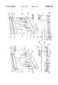
- FIG. 1is a perspective view of a heat exchanger constructed in accordance with the subject invention
- FIG. 2is an enlarged perspective and fragmentary view of the header plate of the invention
- FIG. 3is a side elevational view, partially in cross-section of the molding step.
- FIGS. 4-7illustrate additional embodiments of the subject invention.
- a heat exchanger assembly for transferring heat of a liquidis generally shown at 10.
- the assembly 10comprises a heat exchanger core generally indicated at 12 having adjacent hollow tubes 14 and heat exchanger fins 16 interconnecting the adjacent tubes 14, each of the tubes 14 having a top end and a bottom end.
- the bottom ends and top ends of each of the tubes 14are surrounded by a header 18; i.e., one header 18 surrounds the top ends and another header 18 surrounds the bottom ends of each of the tubes 14 of the core 12.
- a mechanical lock 20is disposed on each of the tubes 14 adjacent each end for mechanical interlocking engagement with the plastic header 18. More specifically, the mechanical lock 20 comprises an annular ring disposed about each of the tubes 14 for securing the engagement between the header 18 and the tubes 14.
- the plastic header 18is molded about the mechanical lock 20 on the tube to engage the plastic header 18 in a mechanical interlocking fashion with each of the tubes 14.
- the assemblyis characterized by the header 18 being plastic and being molded in situ in sealing engagement about each of the top ends and the bottom ends of the tubes 14.
- a cover 22is attached to each of the headers 18 to form an enclosed tank about the top ends and bottom ends of the tubes 14, respectively.
- the covers 22are also plastic and are welded, glued or otherwise diffused with the plastic of the headers 18.
- the tanks at the ends of the tubes 14circulate liquid through the tubes 14 for transferring heat between the liquid and ambient air.
- the liquidis cooled by the process of heat transfer with the fins 16 that takes place as the liquid passes through the tubes 14 of the heat exchanger core 12.
- the method of making the heat exchanger and another embodiment of the present inventionis illustrated in FIG. 3.
- the methodincludes the step of molding the plastic headers generally indicated at 118 in sealing engagement about the ends of the tubes 14. However, before molding the header 118, a mechanical lock 20 is formed on each end of each of the tubes 14. More specifically, this step comprises forming an annular ring as the mechanical lock 20.
- the ends of the tubes 14 and the annular rings 20are disposed in plastic molds 24 which cover the open ends of the tubes 14. Plastic material is injected through the injectors 26 and into the cavities of the molds 24 to surround the end of each tube 14.
- the plastic header 118is molded about the rings 20 and the tubes 14 such that there is a mechanical interlocking engagement between the tubes 14 and the plastic header 118.
- the annular rings 20are brazed, soldered, or otherwise secured about each of the tubes 14 to retain the tubes 14 in the plastic header 118 in a mechanical interlocking fashion.
- the methodincludes the step of attaching a cover 122 to each of the plastic headers 118 to define a tank about the respective top ends and bottom ends of the tubes 14. The enclosed tank has ports for entry and exit of the liquid to be cooled into and out of the heat exchanger core 12.
- FIGS. 4 and 5Another embodiment of the present invention is further illustrated in FIGS. 4 and 5 and includes the plastic header generally indicated at 118.
- the plastic header 118differs only in the header 118 having a bottom portion 128 and a wall 130.
- the wall 130extends upwardly from the bottom portion 128 about the periphery thereof to an upper rim.
- the cover 122is a lid attached to the rim of the headers 118 to enclose the tank.
- the header 118surrounds each of the top end and the bottom end of the tubes 14 with a cover 122 associated with each header 118.
- FIGS. 6 and 7Another embodiment is illustrated in FIGS. 6 and 7 and includes the cover generally indicated at 122. The only difference is that the cover 122 also includes a side wall 132. The wall 132 of the cover 122 has a lower rim that attaches to the upper rim of the header generally indicated at 118.
Landscapes
- Engineering & Computer Science (AREA)
- Mechanical Engineering (AREA)
- Physics & Mathematics (AREA)
- Thermal Sciences (AREA)
- General Engineering & Computer Science (AREA)
- Manufacturing & Machinery (AREA)
- Heat-Exchange Devices With Radiators And Conduit Assemblies (AREA)
Abstract
Description
This invention relates to a heat exchanger assembly of the type for transferring heat between a liquid and ambient air and method of making the same.
The object of a heat exchanger assembly is to maximize heat transfer efficiency at the lowest possible manufacturing cost. The object of the present invention is to prevent leaks caused by stress and cracks created as a result of assembling the components of the heat exchanger assembly. Such heat exchangers include adjacent hollow tubes interconnected by heat exchanger fins. The tubes have top ends and bottom ends that attach to header plates. A cover attaches to each of the header plates attached to the ends of the tubes to form a tank for holding liquid to be cooled in the heat exchanger assembly. The prior art heat exchanger has not provided for bonding a plastic header to the tubes to prevent leaks with ease and economical fabrication.
Typically, the header plates and tubes are made of some form of metal such as brass. They are bonded together by a brazing process in an oven. This method is disclosed in U.S. Pat. No. 4,741,394. In the prior art, methods for bonding a plastic header plate to another plastic component of the heat exchanger are disclosed. For example, U.S. Pat. No. 5,182,856 discloses a heat exchanger having disk oil coolers surrounded by a plastic covering that is welded to a plastic lid. Another example includes U.S. Pat. No. 4,066,122 in which the entire radiator consists of plastic material and the plastic components of the radiator are welded together after being fastened together with straps. Further, U.S. Pat. Nos. 4,565,223 and 5,107,924 disclose methods of joining the plastic header plate with a plastic water tank.
A heat exchanger assembly comprising a heat exchanger core having adjacent hollow tubes and heat exchanger fins interconnecting the adjacent tubes, each of the tubes having a top end and a bottom end; a header surrounding the top ends and the bottom ends of each of the tubes of the core, a cover attached to each of the headers to form an enclosed tank about the respective top ends and bottom ends of the tubes; the assembly is characterized by at least one of the headers being plastic and molded in sealing engagement about one of the ends of the tubes.
The invention includes a method of making the heat exchanger by molding at least one of the header tanks in sealing engagement about one of said ends of said tubes. Accordingly, the subject invention provides a heat exchanger having a plastic header that is sealed to prevent cracks and stress that cause leaks and that is easily and economically fabricated. The prior art methods and assemblies fail to address the need to bond the plastic header to the cover and the tubes of the heat exchanger unit.
Other advantages of the present invention will be readily appreciated as the same becomes better understood by reference to the following detailed description when considered in connection with the accompanying drawings wherein:
FIG. 1 is a perspective view of a heat exchanger constructed in accordance with the subject invention;
FIG. 2 is an enlarged perspective and fragmentary view of the header plate of the invention;
FIG. 3 is a side elevational view, partially in cross-section of the molding step, and
FIGS. 4-7 illustrate additional embodiments of the subject invention.
Referring to the Figures, wherein like numerals indicate like or corresponding parts throughout the several views, a heat exchanger assembly for transferring heat of a liquid is generally shown at 10.
Theassembly 10 comprises a heat exchanger core generally indicated at 12 having adjacenthollow tubes 14 and heat exchanger fins 16 interconnecting theadjacent tubes 14, each of thetubes 14 having a top end and a bottom end. The bottom ends and top ends of each of thetubes 14 are surrounded by aheader 18; i.e., oneheader 18 surrounds the top ends and anotherheader 18 surrounds the bottom ends of each of thetubes 14 of thecore 12. Amechanical lock 20 is disposed on each of thetubes 14 adjacent each end for mechanical interlocking engagement with theplastic header 18. More specifically, themechanical lock 20 comprises an annular ring disposed about each of thetubes 14 for securing the engagement between theheader 18 and thetubes 14. Theplastic header 18 is molded about themechanical lock 20 on the tube to engage theplastic header 18 in a mechanical interlocking fashion with each of thetubes 14. The assembly is characterized by theheader 18 being plastic and being molded in situ in sealing engagement about each of the top ends and the bottom ends of thetubes 14.
To complete the heat exchanger, acover 22 is attached to each of theheaders 18 to form an enclosed tank about the top ends and bottom ends of thetubes 14, respectively. Thecovers 22 are also plastic and are welded, glued or otherwise diffused with the plastic of theheaders 18. The tanks at the ends of thetubes 14 circulate liquid through thetubes 14 for transferring heat between the liquid and ambient air. The liquid is cooled by the process of heat transfer with thefins 16 that takes place as the liquid passes through thetubes 14 of theheat exchanger core 12.
The method of making the heat exchanger and another embodiment of the present invention is illustrated in FIG. 3. The method includes the step of molding the plastic headers generally indicated at 118 in sealing engagement about the ends of thetubes 14. However, before molding theheader 118, amechanical lock 20 is formed on each end of each of thetubes 14. More specifically, this step comprises forming an annular ring as themechanical lock 20.
The ends of thetubes 14 and theannular rings 20 are disposed inplastic molds 24 which cover the open ends of thetubes 14. Plastic material is injected through theinjectors 26 and into the cavities of themolds 24 to surround the end of eachtube 14. Theplastic header 118 is molded about therings 20 and thetubes 14 such that there is a mechanical interlocking engagement between thetubes 14 and theplastic header 118. Theannular rings 20 are brazed, soldered, or otherwise secured about each of thetubes 14 to retain thetubes 14 in theplastic header 118 in a mechanical interlocking fashion. In order to hold the liquid to be cooled, the method includes the step of attaching acover 122 to each of theplastic headers 118 to define a tank about the respective top ends and bottom ends of thetubes 14. The enclosed tank has ports for entry and exit of the liquid to be cooled into and out of theheat exchanger core 12.
Another embodiment of the present invention is further illustrated in FIGS. 4 and 5 and includes the plastic header generally indicated at 118. Theplastic header 118 differs only in theheader 118 having abottom portion 128 and awall 130. Thewall 130 extends upwardly from thebottom portion 128 about the periphery thereof to an upper rim. Thecover 122 is a lid attached to the rim of theheaders 118 to enclose the tank. Theheader 118 surrounds each of the top end and the bottom end of thetubes 14 with acover 122 associated with eachheader 118.
Another embodiment is illustrated in FIGS. 6 and 7 and includes the cover generally indicated at 122. The only difference is that thecover 122 also includes aside wall 132. Thewall 132 of thecover 122 has a lower rim that attaches to the upper rim of the header generally indicated at 118.
The invention has been described in an illustrative manner, and it is to be understood that the terminology which has been used is intended to be in the nature of words of description rather than of limitation.
Obviously, many modifications and variations of the present invention are possible in light of the above teachings. It is, therefore, to be understood that within the scope of the appended claims, wherein reference numerals are merely for convenience and are not to be in any way limiting, the invention may be practiced otherwise than as specifically described.
Claims (6)
1. A heat exchanger assembly comprising:
a heat exchanger core (12) having adjacent hollow tubes (14) and heat exchanger fins (16) interconnecting said adjacent tubes (14), each of said tubes (14) having a top end and a bottom end;
a header (18) surrounding each of said top ends and said bottom ends of said tubes (14) of said core (12);
a cover (22) attached to each of said headers (18) to form a tank about said respective top ends and bottom ends of said tubes (14);
at least one of said headers (18) being plastic and molded in sealing engagement about one of said ends of said tubes (14);
said assembly characterized by an independent annular ring (20) disposed about each of said tubes (14) and said plastic header (18) is molded into mechanical interlocking engagement with said annular ring (20).
2. A heat exchanger assembly comprising:
a heat exchanger core (12) having adjacent hollow tubes (14) and heat exchanger fins (16) interconnecting said adjacent tubes (14) each of said tubes (14) having a top end and a bottom end,
a header (18) surrounding each of said top ends and said bottom ends of said tubes (14) of said core (12);
a cover (22) attached to each of said headers (18) to form a tank about said respective top ends and bottom ends of said tubes (14);
said assembly characterized by at least one of said headers (18) being plastic and molded in sealing engagement about one of said ends of said tubes (14);
said header (118) including a bottom portion (128) and a wall (130) extending from said bottom portion (128), and said cover (122) being attached to said header (118).
3. An assembly as set forth in claim 2 wherein said cover (122) includes a lid portion and a wall (132) extending from said lid portion, and said wall (132) is attached to said header (118).
4. A method of making a heat exchanger of the type having a heat exchanger core (12) having adjacent hollow tubes (14) and heat exchanger fins (16) interconnecting said adjacent tubes (14), each of said tubes (14) having a top end and a bottom end, and a plastic header (18) surrounding each of said top ends and said bottom ends of said tubes (14) of said core (12), and
said method comprising the steps of placing an independent annular ring (20) about each of the tubes (14) and molding at least one of said headers (18) in mechanical interlocking engagement with the rings (20) and in sealing engagement about one of said ends of said tubes (14).
5. A method of making a heat exchanger of the type having a heat exchanger core (12) having adjacent hollow tubes (14) and heat exchanger fins (16) interconnecting said adjacent tubes (14) each of said tubes (14) having a top end and a bottom end, and a plastic header (18) surrounding each of said top ends and said bottom ends of said tubes (14) of said core (12), and
said method comprising the steps of molding at least one of said headers (18) in sealing engagement about one of said ends of said tubes (14); molding said plastic header (118) having a bottom portion (128) and a wall (130) extending from said bottom portion (128), and attaching said cover (122) to each of said headers (118) to enclose said headers (118) about said respective top ends and bottom ends of said tubes (14).
6. A method as set forth in claim 5 further defined as attaching said cover (122) including a lid portion and a wall (132) extending from said lid portion to each of said headers (118) to enclose said headers (118) about said respective top ends and bottom ends of said tubes (14).
Priority Applications (1)
| Application Number | Priority Date | Filing Date | Title |
|---|---|---|---|
| US08/828,756US5865244A (en) | 1997-03-25 | 1997-03-25 | Plastic header tank matrix and method of making same |
Applications Claiming Priority (1)
| Application Number | Priority Date | Filing Date | Title |
|---|---|---|---|
| US08/828,756US5865244A (en) | 1997-03-25 | 1997-03-25 | Plastic header tank matrix and method of making same |
Publications (1)
| Publication Number | Publication Date |
|---|---|
| US5865244Atrue US5865244A (en) | 1999-02-02 |
Family
ID=25252662
Family Applications (1)
| Application Number | Title | Priority Date | Filing Date |
|---|---|---|---|
| US08/828,756Expired - Fee RelatedUS5865244A (en) | 1997-03-25 | 1997-03-25 | Plastic header tank matrix and method of making same |
Country Status (1)
| Country | Link |
|---|---|
| US (1) | US5865244A (en) |
Cited By (32)
| Publication number | Priority date | Publication date | Assignee | Title |
|---|---|---|---|---|
| KR100342713B1 (en)* | 2000-02-11 | 2002-07-04 | 구자홍 | Evaporator for Refrigerator And Method for Manufacturing Header of Evaporator |
| KR100363969B1 (en)* | 2000-02-11 | 2002-12-11 | 엘지전자 주식회사 | Evaporator for Refrigerator And Method for Manufacturing Header of Evaporator |
| US6543404B2 (en) | 2001-04-04 | 2003-04-08 | Dow Global Technologies, Inc. | Adhesively bonded engine intake manifold assembly |
| US20040040699A1 (en)* | 2002-08-27 | 2004-03-04 | Lg Electronics Inc. | Structure for preventing refrigerant from leaking in heat exchanger and method for forming the same |
| US20040173342A1 (en)* | 2001-05-11 | 2004-09-09 | Hajime Sugito | Cooling device boiling and condensing refrigerant |
| US20050034847A1 (en)* | 2003-08-11 | 2005-02-17 | Robert Graham | Monolithic tube sheet and method of manufacture |
| US20050051314A1 (en)* | 2002-11-22 | 2005-03-10 | Gea Luftkuhler Gmbh | Heat exchanger, and method of making a heat exchanger |
| US20050140095A1 (en)* | 2003-12-29 | 2005-06-30 | Anis Muhammad | Insert molded structure and method for the manufacture thereof |
| US6971438B2 (en)* | 2000-12-28 | 2005-12-06 | Honda Giken Kogyo Kabushiki Kaisha | Vehicle radiator device |
| US20060000580A1 (en)* | 2004-06-21 | 2006-01-05 | Veleo Climatisation S.A. | Casing with external seal and immobilization cover for a passenger heating, ventilation and/or air conditioning installation |
| US20060108435A1 (en)* | 2004-11-24 | 2006-05-25 | Kozdras Mark S | By-pass valve for heat exchanger |
| EP1744117A1 (en)* | 2005-07-15 | 2007-01-17 | DSM IP Assets B.V. | Manifold for heat exchanger |
| US20070039723A1 (en)* | 2005-08-18 | 2007-02-22 | Alex Latcau | Header extension to retain core cover and maintain constant compression on outer fins |
| US20080053644A1 (en)* | 2006-08-31 | 2008-03-06 | Klaus Beetz | Heat exchanger unit |
| US7360519B2 (en) | 2003-07-10 | 2008-04-22 | Dow Global Technologies, Inc. | Engine intake manifold assembly |
| US20090139703A1 (en)* | 2005-07-15 | 2009-06-04 | Antonius Maria Vet | Automotive heat exchanger |
| WO2009121320A1 (en)* | 2008-04-02 | 2009-10-08 | Terrawater Gmbh | Method for producing a capacitor |
| US20100206535A1 (en)* | 2007-10-12 | 2010-08-19 | Carrier Corporation | Heat exchangers having baffled manifolds |
| US20110165675A1 (en)* | 2007-12-21 | 2011-07-07 | Edwards Lifesciences Corporation | Capping bioprosthetic tissue to reduce calcification |
| WO2011143515A3 (en)* | 2010-05-13 | 2012-08-23 | Richardson Cooling Packages, LLC | Heat exchanger tank and heat exchanger assembly |
| US20130105127A1 (en)* | 2010-05-06 | 2013-05-02 | Heatmatrix Group B.V. | Heat exchanger tube sheet, a heat exchanger and a method of manufacturing a heat exachanger tube sheet |
| US8561679B2 (en) | 2010-05-13 | 2013-10-22 | Richardson Cooling Packages, LLC | Heat exchanger header and related methods and apparatuses |
| US20140124974A1 (en)* | 2012-11-08 | 2014-05-08 | Charles George Williams | Molding apparatus and method for operating same |
| WO2014176465A1 (en)* | 2013-04-24 | 2014-10-30 | Xiaodong Xiang | Cooling mechanism for led light using 3-d phase change heat transfer |
| DE102014218677A1 (en)* | 2014-09-17 | 2016-03-17 | Mahle International Gmbh | Heat exchanger and method for producing a heat exchanger |
| EP3091208A1 (en)* | 2015-04-22 | 2016-11-09 | Mahle International GmbH | Fresh air supplying device for an internal combustion engine and corresponding manufacturing method |
| CN107110610A (en)* | 2014-09-24 | 2017-08-29 | 法雷奥热系统公司 | Heat exchanger, in particular for a motor vehicle, and method for manufacturing such a heat exchanger |
| US20170268833A1 (en)* | 2014-09-25 | 2017-09-21 | Mahle International Gmbh | Arrangement for a temperature control device, and temperature control device |
| DE102016111201A1 (en)* | 2016-06-20 | 2017-12-21 | Volkswagen Aktiengesellschaft | Method for producing a heat exchanger |
| EP3453996A1 (en)* | 2017-09-12 | 2019-03-13 | Mahle International GmbH | Method for producing a heat exchanger |
| US10767938B2 (en) | 2019-01-15 | 2020-09-08 | Denso International America, Inc. | Heat exchanger with a plastic header plate |
| US11590608B2 (en)* | 2016-12-12 | 2023-02-28 | Daicel Polymer Ltd. | Sealing method |
Citations (11)
| Publication number | Priority date | Publication date | Assignee | Title |
|---|---|---|---|---|
| US3633660A (en)* | 1970-11-16 | 1972-01-11 | Young Radiator Co | Plastic bonding of heat-exchanger core-unitsto header-plates |
| US3993126A (en)* | 1973-07-27 | 1976-11-23 | Delanair Limited | Heat exchanger |
| US4066122A (en)* | 1974-06-20 | 1978-01-03 | Hoechst Aktiengesellschaft | Multi-layer radiator of plastic material and process for its manufacture |
| US4117884A (en)* | 1975-03-21 | 1978-10-03 | Air Frohlich Ag Fur Energie-Ruckgewinnung | Tubular heat exchanger and process for its manufacture |
| US4142581A (en)* | 1976-04-02 | 1979-03-06 | Hitachi, Ltd. | Tube-hole structure for expanded tube-to-tube-sheet joint |
| US4323115A (en)* | 1980-09-26 | 1982-04-06 | Chicago Bridge & Iron Company | Shell and tube heat exchanger with polymeric tube sheets |
| US4576223A (en)* | 1982-12-22 | 1986-03-18 | Sueddeutsche Kuehlerfabrik Julius Fr. Behr Gmbh & Co. Kg | Heat exchanger and process for its manufacture |
| US4741394A (en)* | 1986-08-11 | 1988-05-03 | The Furukawa Electric Co., Ltd. | Radiator for motor cars |
| SU1688103A1 (en)* | 1989-12-28 | 1991-10-30 | Центральное Научно-Исследовательский Институт "Лот" | Method of manufacture of tube sheets for heat-exchange apparatus |
| US5107924A (en)* | 1990-03-02 | 1992-04-28 | Behr Gmbh & Co. | Plastic radiator tank for heat exchangers |
| US5182856A (en)* | 1990-12-28 | 1993-02-02 | Behr Gmbh & Co. | Heat exchanger |
- 1997
- 1997-03-25USUS08/828,756patent/US5865244A/ennot_activeExpired - Fee Related
Patent Citations (11)
| Publication number | Priority date | Publication date | Assignee | Title |
|---|---|---|---|---|
| US3633660A (en)* | 1970-11-16 | 1972-01-11 | Young Radiator Co | Plastic bonding of heat-exchanger core-unitsto header-plates |
| US3993126A (en)* | 1973-07-27 | 1976-11-23 | Delanair Limited | Heat exchanger |
| US4066122A (en)* | 1974-06-20 | 1978-01-03 | Hoechst Aktiengesellschaft | Multi-layer radiator of plastic material and process for its manufacture |
| US4117884A (en)* | 1975-03-21 | 1978-10-03 | Air Frohlich Ag Fur Energie-Ruckgewinnung | Tubular heat exchanger and process for its manufacture |
| US4142581A (en)* | 1976-04-02 | 1979-03-06 | Hitachi, Ltd. | Tube-hole structure for expanded tube-to-tube-sheet joint |
| US4323115A (en)* | 1980-09-26 | 1982-04-06 | Chicago Bridge & Iron Company | Shell and tube heat exchanger with polymeric tube sheets |
| US4576223A (en)* | 1982-12-22 | 1986-03-18 | Sueddeutsche Kuehlerfabrik Julius Fr. Behr Gmbh & Co. Kg | Heat exchanger and process for its manufacture |
| US4741394A (en)* | 1986-08-11 | 1988-05-03 | The Furukawa Electric Co., Ltd. | Radiator for motor cars |
| SU1688103A1 (en)* | 1989-12-28 | 1991-10-30 | Центральное Научно-Исследовательский Институт "Лот" | Method of manufacture of tube sheets for heat-exchange apparatus |
| US5107924A (en)* | 1990-03-02 | 1992-04-28 | Behr Gmbh & Co. | Plastic radiator tank for heat exchangers |
| US5182856A (en)* | 1990-12-28 | 1993-02-02 | Behr Gmbh & Co. | Heat exchanger |
Cited By (63)
| Publication number | Priority date | Publication date | Assignee | Title |
|---|---|---|---|---|
| KR100363969B1 (en)* | 2000-02-11 | 2002-12-11 | 엘지전자 주식회사 | Evaporator for Refrigerator And Method for Manufacturing Header of Evaporator |
| KR100342713B1 (en)* | 2000-02-11 | 2002-07-04 | 구자홍 | Evaporator for Refrigerator And Method for Manufacturing Header of Evaporator |
| US6971438B2 (en)* | 2000-12-28 | 2005-12-06 | Honda Giken Kogyo Kabushiki Kaisha | Vehicle radiator device |
| US20040231628A1 (en)* | 2001-04-04 | 2004-11-25 | Dow Global Technologies, Inc. | Adhesively bonded engine intake manifold assembly |
| US7475664B2 (en) | 2001-04-04 | 2009-01-13 | Dow Global Technologies Inc | Adhesively bonded engine intake manifold assembly |
| US20070251483A1 (en)* | 2001-04-04 | 2007-11-01 | Dow Global Technologies, Inc. | Adhesively bonded engine intake manifold assembly |
| US6739302B2 (en) | 2001-04-04 | 2004-05-25 | Dow Global Technologies, Inc. | Adhesively bonded engine intake manifold assembly |
| US7213560B2 (en) | 2001-04-04 | 2007-05-08 | Dow Global Technologies, Inc. | Adhesively bonded engine intake manifold assembly |
| US6543404B2 (en) | 2001-04-04 | 2003-04-08 | Dow Global Technologies, Inc. | Adhesively bonded engine intake manifold assembly |
| US7017657B2 (en) | 2001-05-11 | 2006-03-28 | Denso Corporation | Cooling device boiling and condensing refrigerant |
| US20040173342A1 (en)* | 2001-05-11 | 2004-09-09 | Hajime Sugito | Cooling device boiling and condensing refrigerant |
| US20070130770A1 (en)* | 2002-08-27 | 2007-06-14 | Lg Electronics Inc. | Structure for preventing refrigerant from leaking in heat exchanger and method for forming the same |
| US20040040699A1 (en)* | 2002-08-27 | 2004-03-04 | Lg Electronics Inc. | Structure for preventing refrigerant from leaking in heat exchanger and method for forming the same |
| AU2003236484B2 (en)* | 2002-08-27 | 2009-04-23 | Lg Electronics Inc. | Structure for preventing refrigerant from leaking in heat exchanger and method for forming the same |
| EP1394492A3 (en)* | 2002-08-27 | 2005-08-17 | Lg Electronics Inc. | Structure for preventing refrigerant from leaking in heat exchanger and method for forming the same |
| US7726025B2 (en)* | 2002-08-27 | 2010-06-01 | Lg Electronics Inc. | Structure for preventing refrigerant from leaking in heat exchanger and method for forming the same |
| AU2003236484B8 (en)* | 2002-08-27 | 2009-05-14 | Lg Electronics Inc. | Structure for preventing refrigerant from leaking in heat exchanger and method for forming the same |
| US6929060B2 (en)* | 2002-11-22 | 2005-08-16 | GEA Luftkühler GmbH | Heat exchanger, and method of making a heat exchanger |
| EP1422489A3 (en)* | 2002-11-22 | 2010-03-31 | GEA LUFTKÜHLER GmbH | Heat exchanger |
| US20050051314A1 (en)* | 2002-11-22 | 2005-03-10 | Gea Luftkuhler Gmbh | Heat exchanger, and method of making a heat exchanger |
| US7360519B2 (en) | 2003-07-10 | 2008-04-22 | Dow Global Technologies, Inc. | Engine intake manifold assembly |
| US20050034847A1 (en)* | 2003-08-11 | 2005-02-17 | Robert Graham | Monolithic tube sheet and method of manufacture |
| US7240724B2 (en)* | 2003-08-11 | 2007-07-10 | Graham Robert G | Monolithic tube sheet and method of manufacture |
| US20050140095A1 (en)* | 2003-12-29 | 2005-06-30 | Anis Muhammad | Insert molded structure and method for the manufacture thereof |
| US7669640B2 (en)* | 2004-06-21 | 2010-03-02 | Valeo Climatisation S.A. | Casing with external seal and immobilization cover for a passenger heating, ventilation and/or air conditioning installation |
| US20060000580A1 (en)* | 2004-06-21 | 2006-01-05 | Veleo Climatisation S.A. | Casing with external seal and immobilization cover for a passenger heating, ventilation and/or air conditioning installation |
| US20060108435A1 (en)* | 2004-11-24 | 2006-05-25 | Kozdras Mark S | By-pass valve for heat exchanger |
| US7540431B2 (en) | 2004-11-24 | 2009-06-02 | Dana Canada Corporation | By-pass valve for heat exchanger |
| US20090139703A1 (en)* | 2005-07-15 | 2009-06-04 | Antonius Maria Vet | Automotive heat exchanger |
| EP1744117A1 (en)* | 2005-07-15 | 2007-01-17 | DSM IP Assets B.V. | Manifold for heat exchanger |
| US20070039723A1 (en)* | 2005-08-18 | 2007-02-22 | Alex Latcau | Header extension to retain core cover and maintain constant compression on outer fins |
| US20080053644A1 (en)* | 2006-08-31 | 2008-03-06 | Klaus Beetz | Heat exchanger unit |
| EP1895258A3 (en)* | 2006-08-31 | 2010-11-24 | Mahle International GmbH | Heat exchange apparatus |
| US20100206535A1 (en)* | 2007-10-12 | 2010-08-19 | Carrier Corporation | Heat exchangers having baffled manifolds |
| US20110165675A1 (en)* | 2007-12-21 | 2011-07-07 | Edwards Lifesciences Corporation | Capping bioprosthetic tissue to reduce calcification |
| US20110006455A1 (en)* | 2008-04-02 | 2011-01-13 | Terrawater Gmbh | Method for Producing a Condenser |
| WO2009121320A1 (en)* | 2008-04-02 | 2009-10-08 | Terrawater Gmbh | Method for producing a capacitor |
| US8128855B2 (en) | 2008-04-02 | 2012-03-06 | Terrawater Gmbh | Method for producing a condenser |
| US20130105127A1 (en)* | 2010-05-06 | 2013-05-02 | Heatmatrix Group B.V. | Heat exchanger tube sheet, a heat exchanger and a method of manufacturing a heat exachanger tube sheet |
| US9429365B2 (en)* | 2010-05-06 | 2016-08-30 | Heatmatrix Group B.V. | Heat exchanger tube sheet, a heat exchanger and a method of manufacturing a heat exchanger tube sheet |
| WO2011143515A3 (en)* | 2010-05-13 | 2012-08-23 | Richardson Cooling Packages, LLC | Heat exchanger tank and heat exchanger assembly |
| US8561679B2 (en) | 2010-05-13 | 2013-10-22 | Richardson Cooling Packages, LLC | Heat exchanger header and related methods and apparatuses |
| US8561678B2 (en) | 2010-05-13 | 2013-10-22 | Richardson Cooling Packages, LLC | Heat exchanger tank and related apparatuses |
| US9227353B2 (en)* | 2012-11-08 | 2016-01-05 | Solar Hydronics Corporation | Molding apparatus and method for operating same |
| US20140124974A1 (en)* | 2012-11-08 | 2014-05-08 | Charles George Williams | Molding apparatus and method for operating same |
| US10295167B2 (en)* | 2013-04-24 | 2019-05-21 | Xiaodong Xiang | Cooling mechanism for LED light using 3-D phase change heat transfer |
| WO2014176465A1 (en)* | 2013-04-24 | 2014-10-30 | Xiaodong Xiang | Cooling mechanism for led light using 3-d phase change heat transfer |
| US20160102854A1 (en)* | 2013-04-24 | 2016-04-14 | Xiaodong Xiang | Cooling mechanism for led light using 3-d phase change heat transfer |
| CN105190170B (en)* | 2013-04-24 | 2019-10-22 | 项晓东 | LED lamp cooling mechanism using three-dimensional phase change heat transfer |
| CN105190170A (en)* | 2013-04-24 | 2015-12-23 | 项晓东 | LED lamp cooling mechanism using three-dimensional phase change heat transfer |
| DE102014218677A1 (en)* | 2014-09-17 | 2016-03-17 | Mahle International Gmbh | Heat exchanger and method for producing a heat exchanger |
| WO2016041815A1 (en)* | 2014-09-17 | 2016-03-24 | Mahle International Gmbh | Heat exchanger and method for producing a heat exchanger |
| CN106716037A (en)* | 2014-09-17 | 2017-05-24 | 马勒国际公司 | Heat exchanger and method for producing a heat exchanger |
| US20170261266A1 (en)* | 2014-09-17 | 2017-09-14 | Mahle International Gmbh | Heat exchanger and method for producing a heat exchanger |
| CN107110610A (en)* | 2014-09-24 | 2017-08-29 | 法雷奥热系统公司 | Heat exchanger, in particular for a motor vehicle, and method for manufacturing such a heat exchanger |
| US20170299288A1 (en)* | 2014-09-24 | 2017-10-19 | Valeo Systemes Thermiques | Heat exchanger, especially for motor vehicle, and method for producing such a heat exchanger |
| US20170268833A1 (en)* | 2014-09-25 | 2017-09-21 | Mahle International Gmbh | Arrangement for a temperature control device, and temperature control device |
| EP3091208A1 (en)* | 2015-04-22 | 2016-11-09 | Mahle International GmbH | Fresh air supplying device for an internal combustion engine and corresponding manufacturing method |
| DE102016111201A1 (en)* | 2016-06-20 | 2017-12-21 | Volkswagen Aktiengesellschaft | Method for producing a heat exchanger |
| DE102016111201B4 (en) | 2016-06-20 | 2022-05-12 | Volkswagen Aktiengesellschaft | Process for manufacturing a heat exchanger |
| US11590608B2 (en)* | 2016-12-12 | 2023-02-28 | Daicel Polymer Ltd. | Sealing method |
| EP3453996A1 (en)* | 2017-09-12 | 2019-03-13 | Mahle International GmbH | Method for producing a heat exchanger |
| US10767938B2 (en) | 2019-01-15 | 2020-09-08 | Denso International America, Inc. | Heat exchanger with a plastic header plate |
Similar Documents
| Publication | Publication Date | Title |
|---|---|---|
| US5865244A (en) | Plastic header tank matrix and method of making same | |
| US8181694B2 (en) | Collar rib for heat exchanger header tanks | |
| US6330747B1 (en) | Heat exchanger assembly utilizing grommets and integral cast tanks | |
| US7506681B2 (en) | Brazed headerless core assembly for a modular heat exchanger | |
| US3993126A (en) | Heat exchanger | |
| EP1715280B1 (en) | Aluminium radiator tank with oil cooler clinch fitting | |
| US4461348A (en) | Heat exchanger | |
| US4546822A (en) | Heat exchanger with adhesive seals | |
| US6247232B1 (en) | Method of manufacturing a welded heat exchanger with grommet construction | |
| US4172496A (en) | Heat exchanger assembly | |
| US5373896A (en) | Heat exchanger assembly | |
| US20090139703A1 (en) | Automotive heat exchanger | |
| US20050150647A1 (en) | Transmission oil cooler attachment to aluminum tank | |
| US5870825A (en) | Method of making unitary heat exchanger core | |
| US5182856A (en) | Heat exchanger | |
| JPH07324887A (en) | Multi-tubular type heat exchanger core and its manufacture | |
| US4332068A (en) | Heat exchanger assembly | |
| GB2235973A (en) | Vehicle radiator assemblies | |
| JP3774022B2 (en) | Aluminum alloy heat exchanger | |
| JPH06339767A (en) | Structure of brazing part of metallic vessel | |
| JPH0749030A (en) | Closed type reserve tank | |
| AU2003200154B2 (en) | Welded Heat Exchanger with Grommet Construction | |
| CN113167553A (en) | Heat exchanger | |
| JPH0712487A (en) | oil cooler | |
| CZ12948U1 (en) | Sealing system of lids of a heat-exchange apparatus for cooling oil of internal combustion engines |
Legal Events
| Date | Code | Title | Description |
|---|---|---|---|
| AS | Assignment | Owner name:BEHR AMERICA, INC., SOUTH CAROLINA Free format text:ASSIGNMENT OF ASSIGNORS INTEREST;ASSIGNOR:MOSER, GEORGE;REEL/FRAME:008506/0429 Effective date:19970321 | |
| FPAY | Fee payment | Year of fee payment:4 | |
| REMI | Maintenance fee reminder mailed | ||
| LAPS | Lapse for failure to pay maintenance fees | ||
| STCH | Information on status: patent discontinuation | Free format text:PATENT EXPIRED DUE TO NONPAYMENT OF MAINTENANCE FEES UNDER 37 CFR 1.362 | |
| FP | Expired due to failure to pay maintenance fee | Effective date:20070202 |