US5865128A - Folding leg mechanism - Google Patents
Folding leg mechanismDownload PDFInfo
- Publication number
- US5865128A US5865128AUS08/896,318US89631897AUS5865128AUS 5865128 AUS5865128 AUS 5865128AUS 89631897 AUS89631897 AUS 89631897AUS 5865128 AUS5865128 AUS 5865128A
- Authority
- US
- United States
- Prior art keywords
- links
- rod
- leg
- platform
- receiving slot
- Prior art date
- Legal status (The legal status is an assumption and is not a legal conclusion. Google has not performed a legal analysis and makes no representation as to the accuracy of the status listed.)
- Expired - Lifetime
Links
Images


Classifications
- A—HUMAN NECESSITIES
- A47—FURNITURE; DOMESTIC ARTICLES OR APPLIANCES; COFFEE MILLS; SPICE MILLS; SUCTION CLEANERS IN GENERAL
- A47B—TABLES; DESKS; OFFICE FURNITURE; CABINETS; DRAWERS; GENERAL DETAILS OF FURNITURE
- A47B3/00—Folding or stowable tables
- A47B3/08—Folding or stowable tables with legs pivoted to top or underframe
- A47B3/091—Folding or stowable tables with legs pivoted to top or underframe with struts supporting the legs
- A47B3/0911—Folding or stowable tables with legs pivoted to top or underframe with struts supporting the legs the struts being permanently connected to top and leg or underframe and leg
- A47B3/0912—Folding or stowable tables with legs pivoted to top or underframe with struts supporting the legs the struts being permanently connected to top and leg or underframe and leg the strut being of two parts foldable relative to one another
Definitions
- the present inventionrelates generally to furniture. More particularly, the invention concerns a novel folding leg mechanism for use in connecting folding legs to table tops and the like.
- Folding leg mechanisms of various designs for connecting folding legs to support platforms, such as table topshave been suggested in the past.
- these mechanismscomprise one or more pairs of pivotally interconnected links with one of the links being connected to the support platform and the other being connected to the folding legs.
- Folding leg mechanisms for larger tables such as banquet tablesgenerally rely on gravity type locking devices to prevent accidental collapse of the linkage when the table is in the operable, upright position.
- These devicesusually comprise round or rectangular shaped metal tubes that capture the linkage at the pivot point to restrain it from collapsing.
- These devicesare effective as locks but are cumbersome in use and are difficult to disengage to enable the legs to be folded into a stored position.
- locking sleeve type devicesmust be manually moved away from the pivot location before the linkage can be folded for storage. If the locking sleeve is not positioned correctly with respect to the pivot point, the linkage tends to bind against the restraint device when the leg is being folded.
- the userIn operating the prior art folding leg mechanisms, the user generally grasps the leg itself to move it toward the folded position. However, in so doing the leg acts as a lever tending to further force the locking device into a binding condition thereby exposing the linkage and the leg to permanent damage. It is one object of the present invention to eliminate the foregoing problem by providing a locking mechanism which is very easy to move into a disengagement position, while at the same time providing a positive means for preventing accidental collapse of the mechanism when the legs which support the work platform are in an extended, operable position.
- one form of the folding leg mechanism of the inventioncomprises a transversely extending rod, the ends of which reside within a uniquely configured slot formed in the leg engaging links of a pair of links that interconnect with the folding legs of the table.
- the rodmoves either by force of gravity or by the urging of a specially designed spring member into an arcuate-shaped, keyhole-like end portion of the slot which lockably receives the ends of the rod.
- the rodneed only to be moved upwardly a short distance so that the ends thereof move from the keyhole-like end portion of the slot into the channel shaped portion of the slot.
- the rod endsare at all times either within the keyhole-like portion of the slot or are within the open channel-like portion of the slot and, therefore, can never be in a position that will cause undesirable binding of the linkage as the table legs are moved toward the stowed position.
- Each of the leg engaging linkshas a rod receiving slot formed therein which includes a channel portion, a ramp portion located proximate one end of the channel portion and a locking opening disposed proximate the ramp portion.
- a locking rodextends between the platform engaging links with the end portion of the rod being slidably received within the channel portion of the slots formed in the leg engaging links.
- Another object of the inventionis to provide a mechanism of the aforementioned character in which the folding leg mechanism positively prevents accidental collapse of the legs when the legs are in an extended, platform supporting position.
- Another object of the inventionis to provide a mechanism of the character described in the preceding paragraphs which prevents binding of the cooperating linkages as the legs which support the platform are moved toward their stowed configuration.
- Another object of the inventionis to provide a folding leg mechanism which includes a locking member that automatically moves by force of gravity into a locking configuration as the legs which support the platform are moved toward their downward platform support position.
- Another object of the inventionis to provide a folding leg mechanism which includes a locking member that is moved by a spring member into a locking configuration as the legs are moved into their downward platform support position.
- Another object of the inventionis to provide a mechanism of the class described which is simple to manufacture and install, is reliable in operation and requires minimum maintenance.
- FIG. 1is a generally perspective view of a table having a top support platform and folding legs interconnected to the support platform by the novel folding leg mechanism of the invention.
- FIG. 2is a greatly enlarged plan view of one form of the folding leg mechanism of the invention shown in an extended configuration.
- FIG. 3is a bottom plan view of the folding leg mechanism shown in a folded configuration and shown interconnected with the support platform,of the table and with the folding legs of the table.
- FIG. 4is a cross-sectional view taken along lines 4--4 of FIG. 3.
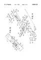
- FIG. 5is a side-elevational view of the folding leg mechanism shown interconnected with the table support platform and with one set of legs thereof, the folding mechanism being shown in a partially folded configuration.
- FIG. 6is an enlarged fragmentary side-elevational view of the locking portion of the folding leg mechanism shown in a position immediately prior to the ends of the locking rod of the folding leg mechanism moving into a locking aperture formed in the leg engaging links of the mechanism.
- FIG. 7is a fragmentary, side-elevational view similar to FIG. 6, but showing further movement of the folding leg mechanism toward the locking configuration.
- FIG. 8is a side-elevational view similar to FIG. 5 showing the folding leg mechanism in a fully extended, locked configuration.
- FIG. 9is an enlarged fragmentary view of the area designated in FIG. 8 by the numeral 9.
- FIG. 10is a fragmentary side-elevational view similar to FIG. 9, but showing the locking rod portion of the folding leg mechanism being moved into a disengagement or release position.
- FIG. 11is a generally perspective, exploded view of one of the pair of cooperating linkages of the folding leg mechanism and a portion of the support platform engaging bracket of the mechanism.
- FIG. 12is a greatly enlarged plan view of an alternate form of the folding leg mechanism of the invention shown in an extended configuration.
- FIG. 13is a generally perspective view of one of the spring members of the mechanism for urging against movement of the locking rod toward a disengaged position.
- FIG. 14is an enlarged view of the area identified in FIG. 12 as "14".
- FIG. 15is a view taken along lines 15--15 of FIG. 12.
- FIG. 16is an enlarged view taken along lines 16--16 of FIG. 12.
- FIG. 17is a view similar to FIG. 16, but shown movement of the locking rod of the mechanism toward the release configuration.
- FIG. 18a side-elevational view similar to FIG. 14 showing the locking rod being moved toward the release position against the urging of one of the spring members as shown in FIG. 17.
- FIG. 19is an enlarged, fragmentary, side-elevational view of the locking portion of the folding leg mechanism shown in an intermediate position wherein the folding leg mechanism is starting to move into the folded configuration with the locking rod moving out of the locking aperture.
- FIG. 20is a view similar to FIG. 19 but showing the locking rod in a fully extended position as a result of the urging of the spring member.
- FIG. 21is a top, fragmentary view showing the spring member in an extended configuration with the locking rod moved into a fully extended position by the spring.
- FIG. 22is a view similar to FIG. 19 but showing the locking mechanism being moved toward a locking configuration within the locking apertures formed in the leg links.
- FIG. 23is a generally perspective, exploded view of one of the pair of cooperation linkages of the folding leg mechanism of this latest form of the invention along with a platform engaging bracket of the mechanism.
- FIG. 24is a generally perspective bottom view of an alternate form of the table construction of the invention which embodies a different type of support leg assembly.
- FIG. 25is an end view of the leg assembly and the folding leg mechanism of this alternate table construction.
- the folding leg mechanism of the present inventionfor use in foldably interconnecting a pair of legs with a support platform is there illustrated and generally designated by the numeral 12.
- the folding leg mechanism of the inventioncomprises first and second spaced-apart platform engaging links 16.
- Links 16are of similar construction and each has a first end 16a and a second end 16b. Pivotally connected to links 16 proximate ends 16a thereof, is a securement means, shown here as a linkage plate 18 which is interconnectable with the lower surface 20a of the support platform 20 of the table construction (FIG. 1).
- Linkage plate 18can be interconnected with support platform 20 by any suitable means such as threaded connectors or screws 21 (FIG. 4).
- first and second leg links 22are of similar construction and each includes first and second end portions 22a and 22b respectively (FIG. 2). As best seen by referring to FIGS. 4 and 5, each leg link 22 is provided proximate end portion 22a with a rod receiving slot 24.
- Rod receiving slots 24are of a unique configuration and slidably receive the end portions 26a of a transversely extending locking rod 26 (FIG. 3). More particularly, each rod receiving slot 24 includes a channel-like portion 24a extending between first and second end portions, a shoulder portion 24b disposed proximate the second end portion, and an arcuate-shaped locking aperture portion 24c disposed proximate the first end portion. Also forming an important aspect of the rod receiving slots 24 is an angled ramp portion 24d. The manner of operation of the locking rod 26 will presently be described.
- Links 22are pivotally interconnected with links 16 by a pivot pin 30 which extends through an aperture 32 provided in end portion 22a of link 22 and through an aperture 34 provided in link 16 proximate end 16b thereof (FIG. 11).
- link 16is interconnected with the securement means or plate 18 by a pivot pin 38 which is receivable through an aperture 40 provided in link 16 proximate end 16a.
- Pin 38also extends through an aperture 42 provided in a downwardly extending leg portion 18a formed on plate 18.
- leg connector meansshown here as a connector member 44.
- Connector member 44includes an intermediate portion provided with an aperture 46 and a lower arcuately shaped portion 48 which is connected as by welding to a transversely extending member 50 which forms a part of one of the leg assemblies 52 of the folding table shown in FIG. 1.
- a locking pin 58Receivable through aperture 46 and through an aperture 56 formed in end 22b of leg 22 is a locking pin 58 (FIG. 11).
- leg assembly 52 of the worktable 59 of one form of the present inventioncomprises, in addition to transversely extending member 50, a pair of downwardly extending legs 60.
- Legs 60are interconnected by any suitable means such as welding with transversely extending member 50 in the manner shown in FIGS. 1 and 3.
- a transversely extending upper rod-like member 62to which the upper ends 60a of leg 60 are interconnected by any suitable means such as welding.
- Each of the members 62 of the leg assemblyis pivotally interconnected with lower surface 20a of the support platform of the worktable by bearing-like brackets 64.
- Brackets 64which are generally U-shaped are constructed so as to permit folding movement of the leg assemblies from the downward operable position shown in FIG. 1 to the stowed, or folded, position shown in FIG. 3 (see also FIGS. 5 and 8).
- platform leg 16is provided with an elongated slot 16c which receives portions 26b of locking rod 26 (FIG. 11) for slidable movement therewithin between a first locking position and a second disengagement position.
- platform engaging link 16is also provided on platform engaging link 16 and an outwardly extending finger-like portion 16d which is received within slot 24 formed in leg length 22.
- finger 16dresides in close proximity with shoulder 24b of slot 24 and acts as a stop to prevent over travel of the links and thereby preclude rod 26 from binding in slot 24 due to the overcenter of the two links.
- FIGS. 5 through 9the operation of the worktable 59 and of the folding leg mechanism of the present form of the invention is there illustrated.
- the legs 60 of the table leg assemblyare being moved from the stowed configuration to an intermediate position.
- the ends 26a of locking rod 26are disposed within a guide slot 16c formed in link 16.
- links 16 and 22move toward an aligned position in a manner shown in FIG. 5.
- rod ends 26amove toward ramp portion 24d of link 22.
- FIG. 10it can be seen that, when it is desired to fold table legs 60 of the worktable 59 into their stowed configuration, an upward force exerted on rod 26 in the direction of the arrow 65 of FIG. 10 will move rod ends 26a out of locking engagement with portion 24c of slot 24 so as to once more permit relative pivotal movement of lengths 16 and 22 about pivot pin 30. Continued force on rod 26 will also move the cooperating links to move into a non-aligned position permitting the legs to fold.
- FIGS. 12 through 23an alternate form of the folding leg mechanism of the invention is there illustrated and generally designated by the numeral 72.
- Mechanism 72is substantially identical to the earlier described mechanism 12, save that biasing means is provided to urge the locking rod into a locking position. Because of this substantial similarity, like numerals are used in FIGS. 12 through 23 to identify like components.
- the folding leg mechanism of this alternate form of the inventioncomprises first and second spaced-apart platform links 16, securement means in the form of a linkage plate 18 pivotally connected thereto and a pair of first and second leg links 22 which are pivotally connected to platform links 16.
- each rod receiving slot 24is formed in each of the leg links 22 and slidably receive the end portions 26a and 26b of an identical, transversely extending locking rod 26 (FIG. 12).
- each rod receiving slot 24includes a channel-like portion 24a, a shoulder portion 24b and an arcuate-shaped locking aperture portion 24c. Also forming an important aspect of the rod receiving slot design is the previously mentioned angled ramp portion 24d.
- biasing means in the form of spring members 74comprise a part of the linkage assembly and function to yieldably urge the rod member of the assembly and into the extended configuration shown in FIG. 12.
- each of the spring members 74comprises a generally "V" shaped body portion 76 having angularly extending, resiliently deformable legs 76a and 76b which terminate in integrally formed feet 78 and 80.
- feet 78are connected to links 16 by connectors 30 while feet 80, each of which is provided with a U-shaped slot 80a and a tongue 80b, reside in pushing engagement with rod 26.
- FIGS. 12 and 17 through 22operation of the folding leg mechanism of this latest form of the invention is there illustrated.
- the folding leg mechanismis in the extended configuration shown in FIG. 12.
- the ends 26b of locking rod 26are disposed within the guide slots 16c formed in links 16.
- links 16 and 22move toward their aligned position shown in FIG. 12.
- rod ends 26amove toward ramp portion 24d of link 22.
- FIGS. 17 and 18when it is desired to fold table legs into their stowed configuration, a force exerted on rod 26 in the direction of the arrow 83, of FIGS. 17 and 18, will yieldably deform spring leg 76a and 76b in the manner shown in FIG. 18 to move rod ends 26a away from locking portions 24c of slots 24 and into channel portions 24a. This movement of the rod ends will permit relative pivotal movement of links 16 and 22 about pivot pin 30 in the manner shown in FIG. 19. Continued movement of the table legs toward the stowed configuration will cause the cooperating links 16 and 22 to move into the orientation shown in FIGS. 20 and 21.
- FIGS. 24 and 25an alternate form of the table construction of the present invention is there illustrated and generally designated by the numeral 102.
- This alternate embodimentis quite similar to the table construction shown in FIGS. 1 through 23 and like numerals are used in FIGS. 24 and 25 to identify like components.
- the folding leg mechanism of this latest form of the inventionis identical to that previously described and comprises first and second space-apart platform engaging links 16. Pivotally connected to links 16 proximate the ends thereof, is a securement means, shown as the previously described linkage plate 18 which is interconnectable with the lower surface 20a of the support platform 20 of the table construction (FIG. 24).
- Legs 106also include lower leg portions 106b which are further spaced than leg portions 106a and terminate in ground engaging extremities 106c. Legs 106 are interconnected by any suitable means such as welding with a transversely extending member 108 in the manner shown in the drawings. Also forming a part of each leg assembly is a transversely extending upper rod-like member 110 to which upper portions 106a are interconnected by any suitable means such as welding. As before, each of the leg assemblies is pivotally interconnected with lower surface 20a of the support platform of the worktable by bearing-like brackets 64 (FIG. 24).
- folding of the leg assemblies of this last form of the inventionis accomplished in the same manner as the folding of leg assemblies 52 through use of the novel folding leg mechanism of the invention.
Landscapes
- Tables And Desks Characterized By Structural Shape (AREA)
Abstract
Description
Claims (20)
Priority Applications (3)
| Application Number | Priority Date | Filing Date | Title |
|---|---|---|---|
| US08/896,318US5865128A (en) | 1997-06-25 | 1997-06-25 | Folding leg mechanism |
| AU75889/98AAU7588998A (en) | 1997-06-25 | 1998-05-21 | Folding leg mechanism |
| PCT/US1998/010450WO1998058564A1 (en) | 1997-06-25 | 1998-05-21 | Folding leg mechanism |
Applications Claiming Priority (1)
| Application Number | Priority Date | Filing Date | Title |
|---|---|---|---|
| US08/896,318US5865128A (en) | 1997-06-25 | 1997-06-25 | Folding leg mechanism |
Publications (1)
| Publication Number | Publication Date |
|---|---|
| US5865128Atrue US5865128A (en) | 1999-02-02 |
Family
ID=25406003
Family Applications (1)
| Application Number | Title | Priority Date | Filing Date |
|---|---|---|---|
| US08/896,318Expired - LifetimeUS5865128A (en) | 1997-06-25 | 1997-06-25 | Folding leg mechanism |
Country Status (3)
| Country | Link |
|---|---|
| US (1) | US5865128A (en) |
| AU (1) | AU7588998A (en) |
| WO (1) | WO1998058564A1 (en) |
Cited By (43)
| Publication number | Priority date | Publication date | Assignee | Title |
|---|---|---|---|---|
| USD414626S (en) | 1998-10-21 | 1999-10-05 | Lifetime Products, Inc. | Utility table |
| US5983807A (en)* | 1998-06-05 | 1999-11-16 | Virco Mfg. Corporation | Lightweight plastic furniture |
| USD419332S (en)* | 1999-05-17 | 2000-01-25 | Lifetime Products, Inc. | Utility table |
| USD420563S (en)* | 1998-11-25 | 2000-02-15 | Lifetime Products, Inc. | Integral spring latch |
| US6371034B1 (en) | 2000-05-22 | 2002-04-16 | Globe Business Furniture Of Tennessee, Inc. | Folding table |
| USD456155S1 (en) | 2001-06-11 | 2002-04-30 | Biofit Engineered Products | Oval shaped cafeteria table |
| US6431092B1 (en) | 1998-10-21 | 2002-08-13 | Lifetime Products, Inc. | Portable folding utility table with center support assembly |
| US6471173B1 (en)* | 2002-01-22 | 2002-10-29 | Shin Yeh Enterprise Co., Ltd. | Foldable frame support device for supporting a top plate used for furniture |
| USD469981S1 (en) | 2001-12-12 | 2003-02-11 | Maxchief Investments Limited | Collapsible table |
| USD470692S1 (en) | 2002-01-28 | 2003-02-25 | Lifetime Products, Inc. | Pair of table legs |
| US6530331B2 (en) | 1998-10-21 | 2003-03-11 | Lifetime Products, Inc. | Portable folding utility table with integral receiving members |
| USD473450S1 (en) | 2002-01-28 | 2003-04-22 | Lifetime Products, Inc. | Latch for securing table legs in an extended position |
| USD476169S1 (en) | 2001-12-12 | 2003-06-24 | Maxchief Investments Limited | Collapsible table |
| USD476504S1 (en) | 2002-08-02 | 2003-07-01 | Royal Alliance Inc. | Table |
| USD476823S1 (en) | 2002-08-02 | 2003-07-08 | Royal Alliance Inc. | Banquet table |
| US6615743B2 (en)* | 2001-08-02 | 2003-09-09 | Chou-Chin Nien | Folding table |
| US6622644B2 (en) | 2001-12-12 | 2003-09-23 | Maxchief Investment Limited | Collapsible table |
| USD480580S1 (en) | 2001-12-12 | 2003-10-14 | Maxchief Investments Limited | Circular collapsible table |
| WO2003086147A1 (en)* | 2002-04-09 | 2003-10-23 | Lifetime Products, Inc. | Pivotal connection of a support brace to a table leg and a table top |
| WO2003086144A1 (en)* | 2002-04-09 | 2003-10-23 | Lifetime Products, Inc. | Pivotal connection of a table leg to a frame |
| US6651568B1 (en) | 2002-07-15 | 2003-11-25 | Maxchief Investments Limited | Collapsible table |
| WO2003087511A3 (en)* | 2002-04-09 | 2003-12-24 | Lifetime Prod Inc | Table leg locking mechanism |
| US20040187747A1 (en)* | 2002-09-24 | 2004-09-30 | Jin Shenghao | Utility table |
| US20040187748A1 (en)* | 2002-09-27 | 2004-09-30 | Jin Shenghao | Table having H-center support assembly |
| US20040237856A1 (en)* | 2002-09-24 | 2004-12-02 | Jin Shenghao | Utility table |
| US20040244656A1 (en)* | 2002-10-11 | 2004-12-09 | Jin Shenghao | Table with center support assembly |
| US20050045074A1 (en)* | 2003-07-09 | 2005-03-03 | Ju-Young Jin | Table |
| US6925665B1 (en) | 2002-10-23 | 2005-08-09 | Eric Hennings | Multiple configuration bed frame system |
| US20050279259A1 (en)* | 1999-01-11 | 2005-12-22 | Strong L C | Frame for a table top |
| USD513140S1 (en) | 2004-07-08 | 2005-12-27 | Lifetime Products, Inc. | Support for a table |
| USD515852S1 (en) | 2004-07-08 | 2006-02-28 | Lifetime Products, Inc. | Leg support for a table |
| USD527930S1 (en) | 2004-09-01 | 2006-09-12 | Lifetime Products, Inc. | Table leg |
| USD529734S1 (en) | 2004-08-31 | 2006-10-10 | Lifetime Products, Inc. | Adjustable table leg |
| US7299754B2 (en) | 1999-01-11 | 2007-11-27 | Stanford Carl R | Table with receiving members |
| US20090293778A1 (en)* | 2008-05-28 | 2009-12-03 | Paul Branch | Support structure for a table |
| US20090293774A1 (en)* | 2008-06-02 | 2009-12-03 | International Truck Intellectual Property Company, Llc | Stowable Table Unit System for a Vehicle |
| US8550012B2 (en)* | 2011-10-27 | 2013-10-08 | Mity-Lite, Inc. | Leg locking and folding mechanism for folding table |
| US8671850B2 (en) | 2011-10-27 | 2014-03-18 | Mity-Lite, Inc. | Convertible tabletop with pivotal modesty panel |
| US20190281972A1 (en)* | 2018-03-19 | 2019-09-19 | Dongguan Shichang Metals Factory Ltd. | Collapsible brace member for a furniture support structure |
| EP3542668A1 (en)* | 2018-03-19 | 2019-09-25 | Dongguan Shichang Metals Factory Ltd. | Collapsible brace member for a furniture support structure |
| WO2019180196A1 (en)* | 2018-03-22 | 2019-09-26 | Panelterra Investments Ltd. | A folding lock mechanism for furniture legs and a piece of furniture with such a mechanism |
| USD885097S1 (en) | 2018-03-16 | 2020-05-26 | Dongguan Shichang Metals Factory Ltd. | Collapsible brace member for a furniture support structure |
| CN112040809A (en)* | 2018-03-22 | 2020-12-04 | 帕纳泰拉投资有限公司 | Folding locking mechanism for furniture legs and furniture with such a mechanism |
Citations (6)
| Publication number | Priority date | Publication date | Assignee | Title |
|---|---|---|---|---|
| US1057545A (en)* | 1911-03-03 | 1913-04-01 | Albert A Griffin | Collapsible table. |
| US2278810A (en)* | 1940-07-17 | 1942-04-07 | Philip M Virtue | Folding brace |
| US2689158A (en)* | 1951-02-05 | 1954-09-14 | Harold R Nielsen | Folding table with spring latch toggle mechanism |
| US2882109A (en)* | 1956-08-16 | 1959-04-14 | Brewer Titchener Corp | Folding lock brace structure |
| US3072451A (en)* | 1960-07-15 | 1963-01-08 | Amtab Mfg Co | Folding table construction |
| US3606846A (en)* | 1969-12-11 | 1971-09-21 | Univeral Oil Products Co | Stowable table and base |
- 1997
- 1997-06-25USUS08/896,318patent/US5865128A/ennot_activeExpired - Lifetime
- 1998
- 1998-05-21WOPCT/US1998/010450patent/WO1998058564A1/enactiveApplication Filing
- 1998-05-21AUAU75889/98Apatent/AU7588998A/ennot_activeAbandoned
Patent Citations (6)
| Publication number | Priority date | Publication date | Assignee | Title |
|---|---|---|---|---|
| US1057545A (en)* | 1911-03-03 | 1913-04-01 | Albert A Griffin | Collapsible table. |
| US2278810A (en)* | 1940-07-17 | 1942-04-07 | Philip M Virtue | Folding brace |
| US2689158A (en)* | 1951-02-05 | 1954-09-14 | Harold R Nielsen | Folding table with spring latch toggle mechanism |
| US2882109A (en)* | 1956-08-16 | 1959-04-14 | Brewer Titchener Corp | Folding lock brace structure |
| US3072451A (en)* | 1960-07-15 | 1963-01-08 | Amtab Mfg Co | Folding table construction |
| US3606846A (en)* | 1969-12-11 | 1971-09-21 | Univeral Oil Products Co | Stowable table and base |
Cited By (102)
| Publication number | Priority date | Publication date | Assignee | Title |
|---|---|---|---|---|
| US5983807A (en)* | 1998-06-05 | 1999-11-16 | Virco Mfg. Corporation | Lightweight plastic furniture |
| US20090229499A1 (en)* | 1998-10-21 | 2009-09-17 | Stanford Carl R | Table |
| US7806060B2 (en) | 1998-10-21 | 2010-10-05 | Lifetime Products, Inc. | Table top with a plurality of closely spaced depressions |
| US8375871B2 (en) | 1998-10-21 | 2013-02-19 | Lifetime Products, Inc. | Table top with a plurality of closely spaced depressions |
| US20110017109A1 (en)* | 1998-10-21 | 2011-01-27 | Stanford Carl R | Table top with a plurality of closely spaced depressions |
| US8042476B2 (en) | 1998-10-21 | 2011-10-25 | Lifetime Products, Inc. | Table with molded plastic table top |
| US6431092B1 (en) | 1998-10-21 | 2002-08-13 | Lifetime Products, Inc. | Portable folding utility table with center support assembly |
| USD414626S (en) | 1998-10-21 | 1999-10-05 | Lifetime Products, Inc. | Utility table |
| US20090223424A1 (en)* | 1998-10-21 | 2009-09-10 | Stanford Carl R | Table |
| US7571686B2 (en) | 1998-10-21 | 2009-08-11 | Lifetime Products, Inc. | Table with molded plastic table top |
| US6530331B2 (en) | 1998-10-21 | 2003-03-11 | Lifetime Products, Inc. | Portable folding utility table with integral receiving members |
| US6550404B2 (en) | 1998-10-21 | 2003-04-22 | Lifetime Products, Inc. | Portable folding utility table with integral table top and lip |
| US7536961B2 (en) | 1998-10-21 | 2009-05-26 | Lifetime Products, Inc. | Table including a plastic table top and attached frame |
| US7533619B2 (en) | 1998-10-21 | 2009-05-19 | Lifetime Products, Inc. | Table with spaced depressions |
| US7143702B2 (en) | 1998-10-21 | 2006-12-05 | Lifetime Products, Inc. | Table with foldable legs |
| US7464654B2 (en) | 1998-10-21 | 2008-12-16 | Lifetime Products, Inc.I | Table with integral receiving members |
| US7461602B2 (en) | 1998-10-21 | 2008-12-09 | Lifetime Products, Inc. | Table with foldable legs |
| US7461603B2 (en) | 1998-10-21 | 2008-12-09 | Lifetime Products, Inc. | Table including a plastic table top and an attached frame |
| US7434522B2 (en) | 1998-10-21 | 2008-10-14 | Lifetime Products, Inc. | Table top with a plurality of closely spaced depressions |
| US20080110378A1 (en)* | 1998-10-21 | 2008-05-15 | Stanford Carl R | Table top with a plurality of closely spaced depressions |
| US20080110379A1 (en)* | 1998-10-21 | 2008-05-15 | Stanford Carl R | Table |
| US20080105171A1 (en)* | 1998-10-21 | 2008-05-08 | Stanford Carl R | Table |
| US20080105170A1 (en)* | 1998-10-21 | 2008-05-08 | Stanford Carl R | Table |
| US6655301B2 (en) | 1998-10-21 | 2003-12-02 | Lifetime Products, Inc. | Portable folding utility table with frame connected to integral lip |
| US7114453B2 (en) | 1998-10-21 | 2006-10-03 | Lifetime Products, Inc. | Table top with a plurality of closely spaced depressions |
| US20040099189A1 (en)* | 1998-10-21 | 2004-05-27 | Stanford Carl R. | Portable folding utility table with frame connected to integral lip |
| US7299755B2 (en) | 1998-10-21 | 2007-11-27 | Lifetime Products, Inc. | Table including a blow-molded plastic table top and an attached frame |
| US9237801B2 (en) | 1998-10-21 | 2016-01-19 | Lifetime Products, Inc. | Table top with a plurality of closely spaced depressions |
| US20070089650A1 (en)* | 1998-10-21 | 2007-04-26 | Stanford Carl R | Table with foldable legs |
| US20070051287A1 (en)* | 1998-10-21 | 2007-03-08 | Stanford Carl R | Table with integral receiving members |
| US8904623B2 (en) | 1998-10-21 | 2014-12-09 | Lifetime Products, Inc. | Table |
| US6832563B2 (en) | 1998-10-21 | 2004-12-21 | Lifetime Products, Inc. | Portable folding utility table with integral receiving members |
| US6848370B1 (en) | 1998-10-21 | 2005-02-01 | Lifetime Products, Inc. | Table with pivotally attached legs |
| US8739707B2 (en) | 1998-10-21 | 2014-06-03 | Lifetime Products, Inc. | Table top |
| US6895872B2 (en) | 1998-10-21 | 2005-05-24 | Lifetime Products, Inc. | Portable folding utility table with frame connected to integral lip |
| US20070034123A1 (en)* | 1998-10-21 | 2007-02-15 | Stanford Carl R | Table top with a plurality of closely spaced depressions |
| US20060266266A1 (en)* | 1998-10-21 | 2006-11-30 | Stanford Carl R | Table including a blow-molded plastic table top and an attached frame |
| US20050211141A1 (en)* | 1998-10-21 | 2005-09-29 | Stanford Carl R | Table including a blow-molded plastic table top and an attached frame |
| US7128002B2 (en) | 1998-10-21 | 2006-10-31 | Lifetime Products, Inc. | Table with integral receiving members |
| US20050268827A1 (en)* | 1998-10-21 | 2005-12-08 | Stanford Carl R | Table top with a plurality of closely spaced depressions |
| US8069796B2 (en) | 1998-10-21 | 2011-12-06 | Lifetime Products, Inc. | Table with molded plastic table top |
| US8438982B2 (en) | 1998-10-21 | 2013-05-14 | Lifetime Products, Inc. | Table with a table top constructed from molded plastic |
| US20060000394A1 (en)* | 1998-10-21 | 2006-01-05 | Stanford Carl R | Table with foldable legs |
| US20060011109A1 (en)* | 1998-10-21 | 2006-01-19 | Sanford Carl R | Table with integral receiving members |
| US8381665B2 (en) | 1998-10-21 | 2013-02-26 | Lifetime Products, Inc. | Table top constructed from molded plastic |
| US7044068B2 (en) | 1998-10-21 | 2006-05-16 | Lifetime Products,Inc. | Table including a blow-molded plastic table top and an attached frame |
| US8381666B2 (en) | 1998-10-21 | 2013-02-26 | Lifetime Products, Inc. | Table top constructed from molded plastic |
| US8074582B2 (en) | 1998-10-21 | 2011-12-13 | Lifetime Products, Inc. | Table with a table top including a plurality of integrally formed depressions |
| USD420563S (en)* | 1998-11-25 | 2000-02-15 | Lifetime Products, Inc. | Integral spring latch |
| US7299754B2 (en) | 1999-01-11 | 2007-11-27 | Stanford Carl R | Table with receiving members |
| US7428872B2 (en) | 1999-01-11 | 2008-09-30 | Lifetime Products, Inc. | Frame for a table top |
| US20050279259A1 (en)* | 1999-01-11 | 2005-12-22 | Strong L C | Frame for a table top |
| USD419332S (en)* | 1999-05-17 | 2000-01-25 | Lifetime Products, Inc. | Utility table |
| US6371034B1 (en) | 2000-05-22 | 2002-04-16 | Globe Business Furniture Of Tennessee, Inc. | Folding table |
| USD456155S1 (en) | 2001-06-11 | 2002-04-30 | Biofit Engineered Products | Oval shaped cafeteria table |
| US6615743B2 (en)* | 2001-08-02 | 2003-09-09 | Chou-Chin Nien | Folding table |
| US6823806B1 (en) | 2001-12-12 | 2004-11-30 | Maxchief Investments Limited | Collapsible table |
| USD469981S1 (en) | 2001-12-12 | 2003-02-11 | Maxchief Investments Limited | Collapsible table |
| USD476169S1 (en) | 2001-12-12 | 2003-06-24 | Maxchief Investments Limited | Collapsible table |
| US6622644B2 (en) | 2001-12-12 | 2003-09-23 | Maxchief Investment Limited | Collapsible table |
| USD480580S1 (en) | 2001-12-12 | 2003-10-14 | Maxchief Investments Limited | Circular collapsible table |
| US6471173B1 (en)* | 2002-01-22 | 2002-10-29 | Shin Yeh Enterprise Co., Ltd. | Foldable frame support device for supporting a top plate used for furniture |
| USD470692S1 (en) | 2002-01-28 | 2003-02-25 | Lifetime Products, Inc. | Pair of table legs |
| USD473450S1 (en) | 2002-01-28 | 2003-04-22 | Lifetime Products, Inc. | Latch for securing table legs in an extended position |
| CN100337568C (en)* | 2002-04-09 | 2007-09-19 | 一生产品有限公司 | Locking device for table legs |
| US7100518B2 (en) | 2002-04-09 | 2006-09-05 | Lifetime Products, Inc. | Pivotal connection of a table leg to a frame |
| WO2003086144A1 (en)* | 2002-04-09 | 2003-10-23 | Lifetime Products, Inc. | Pivotal connection of a table leg to a frame |
| US20030200904A1 (en)* | 2002-04-09 | 2003-10-30 | Strong L. Curtis | Pivotal connection of a table leg to a frame |
| US6971321B1 (en) | 2002-04-09 | 2005-12-06 | Lifetime Products, Inc. | Table leg locking mechanism |
| US6901867B2 (en) | 2002-04-09 | 2005-06-07 | Lifetime Products, Inc. | Pivotal connection of a support brace to a table leg and a table top |
| WO2003086147A1 (en)* | 2002-04-09 | 2003-10-23 | Lifetime Products, Inc. | Pivotal connection of a support brace to a table leg and a table top |
| WO2003087511A3 (en)* | 2002-04-09 | 2003-12-24 | Lifetime Prod Inc | Table leg locking mechanism |
| CN100344247C (en)* | 2002-04-09 | 2007-10-24 | 一生产品有限公司 | Connection of support rods to pivots of table legs and table tops |
| US6651568B1 (en) | 2002-07-15 | 2003-11-25 | Maxchief Investments Limited | Collapsible table |
| USD476504S1 (en) | 2002-08-02 | 2003-07-01 | Royal Alliance Inc. | Table |
| USD476823S1 (en) | 2002-08-02 | 2003-07-08 | Royal Alliance Inc. | Banquet table |
| US20040187747A1 (en)* | 2002-09-24 | 2004-09-30 | Jin Shenghao | Utility table |
| US20040237856A1 (en)* | 2002-09-24 | 2004-12-02 | Jin Shenghao | Utility table |
| US7475642B2 (en) | 2002-09-27 | 2009-01-13 | Lifetime Products, Inc. | Table having H-center support assembly |
| US20040187748A1 (en)* | 2002-09-27 | 2004-09-30 | Jin Shenghao | Table having H-center support assembly |
| US20040244656A1 (en)* | 2002-10-11 | 2004-12-09 | Jin Shenghao | Table with center support assembly |
| US7051662B2 (en) | 2002-10-11 | 2006-05-30 | Lifetime Products, Inc. | Table with center support assembly |
| US6925665B1 (en) | 2002-10-23 | 2005-08-09 | Eric Hennings | Multiple configuration bed frame system |
| US20050045074A1 (en)* | 2003-07-09 | 2005-03-03 | Ju-Young Jin | Table |
| USD515852S1 (en) | 2004-07-08 | 2006-02-28 | Lifetime Products, Inc. | Leg support for a table |
| USD513140S1 (en) | 2004-07-08 | 2005-12-27 | Lifetime Products, Inc. | Support for a table |
| USD529734S1 (en) | 2004-08-31 | 2006-10-10 | Lifetime Products, Inc. | Adjustable table leg |
| USD527930S1 (en) | 2004-09-01 | 2006-09-12 | Lifetime Products, Inc. | Table leg |
| US20090293778A1 (en)* | 2008-05-28 | 2009-12-03 | Paul Branch | Support structure for a table |
| US8096599B2 (en)* | 2008-06-02 | 2012-01-17 | International Truck Intellectual Property Company, Llc | Stowable table unit system for a vehicle |
| US20090293774A1 (en)* | 2008-06-02 | 2009-12-03 | International Truck Intellectual Property Company, Llc | Stowable Table Unit System for a Vehicle |
| US8671850B2 (en) | 2011-10-27 | 2014-03-18 | Mity-Lite, Inc. | Convertible tabletop with pivotal modesty panel |
| US8550012B2 (en)* | 2011-10-27 | 2013-10-08 | Mity-Lite, Inc. | Leg locking and folding mechanism for folding table |
| AU2012203860B2 (en)* | 2011-10-27 | 2016-10-20 | Mity-Lite, Inc. | Leg locking and folding mechanism for folding table |
| USD885097S1 (en) | 2018-03-16 | 2020-05-26 | Dongguan Shichang Metals Factory Ltd. | Collapsible brace member for a furniture support structure |
| US20190281972A1 (en)* | 2018-03-19 | 2019-09-19 | Dongguan Shichang Metals Factory Ltd. | Collapsible brace member for a furniture support structure |
| EP3542668A1 (en)* | 2018-03-19 | 2019-09-25 | Dongguan Shichang Metals Factory Ltd. | Collapsible brace member for a furniture support structure |
| US11129469B2 (en)* | 2018-03-19 | 2021-09-28 | Dongguan Shichang Metals Factory Ltd. | Collapsible brace member for a furniture support structure |
| WO2019180196A1 (en)* | 2018-03-22 | 2019-09-26 | Panelterra Investments Ltd. | A folding lock mechanism for furniture legs and a piece of furniture with such a mechanism |
| CN112040809A (en)* | 2018-03-22 | 2020-12-04 | 帕纳泰拉投资有限公司 | Folding locking mechanism for furniture legs and furniture with such a mechanism |
| US11191351B2 (en)* | 2018-03-22 | 2021-12-07 | Panelterra Investments Ltd. | Folding lock mechanism for furniture legs and a piece of furniture with such a mechanism |
| CN112040809B (en)* | 2018-03-22 | 2023-03-10 | 帕纳泰拉投资有限公司 | Fold locking mechanism for furniture legs and furniture having such a mechanism |
Also Published As
| Publication number | Publication date |
|---|---|
| WO1998058564A1 (en) | 1998-12-30 |
| AU7588998A (en) | 1999-01-04 |
Similar Documents
| Publication | Publication Date | Title |
|---|---|---|
| US5865128A (en) | Folding leg mechanism | |
| US4111454A (en) | Folding baby carriage | |
| US3357729A (en) | Folding brace lock for table leg | |
| US11330900B2 (en) | Auto-locking adjustable bar and structure having same | |
| CA2044451C (en) | Lower joint folding preventing device for one touch type dome shaped tent | |
| US4191111A (en) | Bench folding leg and brace structure | |
| US5109778A (en) | Folding table | |
| US5722507A (en) | Step stool assembly | |
| US4045045A (en) | Foldable child walker | |
| KR940702244A (en) | Multi-level folding stage | |
| US5446931A (en) | Children's playyard | |
| JPH08322644A (en) | Table | |
| CN114269203B (en) | Foldable height-adjustable table | |
| EP2413748A1 (en) | High chair with folding legs | |
| US6086148A (en) | Collapsible picnic table | |
| WO1998024342A1 (en) | Folding table | |
| JP2001512202A (en) | Folding stage | |
| CA2628691C (en) | Foldable table having movable strut-retainer | |
| EP0811100B1 (en) | Folding framework and support legs | |
| US2661554A (en) | Support for ironing tables | |
| US7878583B2 (en) | Foldable high chair | |
| US20070144831A1 (en) | Foldable chair and ladder combination | |
| US20040201268A1 (en) | Kneeling bench | |
| US5478138A (en) | Security device for a foldable chair | |
| US4152010A (en) | Folding baby carriage |
Legal Events
| Date | Code | Title | Description |
|---|---|---|---|
| AS | Assignment | Owner name:VIRCO MFG. CORPORATION, CALIFORNIA Free format text:ASSIGNMENT OF ASSIGNORS INTEREST;ASSIGNOR:TARNAY, MATT;REEL/FRAME:009478/0134 Effective date:19980130 | |
| STCF | Information on status: patent grant | Free format text:PATENTED CASE | |
| AS | Assignment | Owner name:VIRCO MGMT. CORPORATION, CALIFORNIA Free format text:ASSIGNMENT OF ASSIGNORS INTEREST;ASSIGNOR:VIRCO MFG. CORPORATION;REEL/FRAME:010685/0304 Effective date:20000308 | |
| FPAY | Fee payment | Year of fee payment:4 | |
| AS | Assignment | Owner name:WELLS FARGO BANK, NATIONAL ASSOCIATES, AS AGENT, C Free format text:SECURITY INTEREST;ASSIGNOR:VIRCO MGMT. CORPORATION;REEL/FRAME:014981/0579 Effective date:20040127 | |
| FPAY | Fee payment | Year of fee payment:8 | |
| FEPP | Fee payment procedure | Free format text:PAYOR NUMBER ASSIGNED (ORIGINAL EVENT CODE: ASPN); ENTITY STATUS OF PATENT OWNER: LARGE ENTITY | |
| AS | Assignment | Owner name:VIRCO MFG. CORPORATION, CALIFORNIA Free format text:ASSIGNMENT OF ASSIGNORS INTEREST;ASSIGNOR:VIRCO MGMT. CORPORATION;REEL/FRAME:023854/0675 Effective date:20100126 | |
| FPAY | Fee payment | Year of fee payment:12 | |
| AS | Assignment | Owner name:VIRCO MFG. CORPORATION, CALIFORNIA Free format text:RELEASE OF SECURITY INTERESTS IN PATENTS;ASSIGNOR:WELLS FARGO BANK, NATIONAL ASSOCIATION;REEL/FRAME:027546/0190 Effective date:20111222 |