US5864578A - Matched filter-based handoff method and apparatus - Google Patents
Matched filter-based handoff method and apparatusDownload PDFInfo
- Publication number
- US5864578A US5864578AUS08/638,394US63839496AUS5864578AUS 5864578 AUS5864578 AUS 5864578AUS 63839496 AUS63839496 AUS 63839496AUS 5864578 AUS5864578 AUS 5864578A
- Authority
- US
- United States
- Prior art keywords
- spread
- received
- signal
- base station
- spectrum
- Prior art date
- Legal status (The legal status is an assumption and is not a legal conclusion. Google has not performed a legal analysis and makes no representation as to the accuracy of the status listed.)
- Expired - Fee Related
Links
Images


Classifications
- H—ELECTRICITY
- H04—ELECTRIC COMMUNICATION TECHNIQUE
- H04B—TRANSMISSION
- H04B1/00—Details of transmission systems, not covered by a single one of groups H04B3/00 - H04B13/00; Details of transmission systems not characterised by the medium used for transmission
- H04B1/69—Spread spectrum techniques
- H04B1/707—Spread spectrum techniques using direct sequence modulation
- H—ELECTRICITY
- H04—ELECTRIC COMMUNICATION TECHNIQUE
- H04W—WIRELESS COMMUNICATION NETWORKS
- H04W52/00—Power management, e.g. Transmission Power Control [TPC] or power classes
- H04W52/04—Transmission power control [TPC]
- H—ELECTRICITY
- H04—ELECTRIC COMMUNICATION TECHNIQUE
- H04W—WIRELESS COMMUNICATION NETWORKS
- H04W24/00—Supervisory, monitoring or testing arrangements
- H—ELECTRICITY
- H04—ELECTRIC COMMUNICATION TECHNIQUE
- H04W—WIRELESS COMMUNICATION NETWORKS
- H04W36/00—Hand-off or reselection arrangements
- H04W36/02—Buffering or recovering information during reselection ; Modification of the traffic flow during hand-off
- H04W36/023—Buffering or recovering information during reselection
- H—ELECTRICITY
- H04—ELECTRIC COMMUNICATION TECHNIQUE
- H04W—WIRELESS COMMUNICATION NETWORKS
- H04W36/00—Hand-off or reselection arrangements
- H04W36/08—Reselecting an access point
- H—ELECTRICITY
- H04—ELECTRIC COMMUNICATION TECHNIQUE
- H04W—WIRELESS COMMUNICATION NETWORKS
- H04W36/00—Hand-off or reselection arrangements
- H04W36/24—Reselection being triggered by specific parameters
- H04W36/30—Reselection being triggered by specific parameters by measured or perceived connection quality data
- H04W36/302—Reselection being triggered by specific parameters by measured or perceived connection quality data due to low signal strength
Definitions
- This inventionrelates to spread-spectrum communications, and more particularly to a method and apparatus for handing-off a remote unit between two base stations.
- a spread-spectrum communications systemuses message data. Message data requires transmission without error. When a mobile station moves from a first base station to a second base station, the chip sequence used for the channel containing the digital data has to be handed-off so as to not interrupt communications so as to produce errors.
- Multiple coverage areasare employed by mobile communications systems to accommodate communications over a wide geographic region.
- Each geographic areahas several base stations to provide radiotelephones within the base site coverage area with a number of radiotelephone communication channels.
- Simulcast communication systems and cellular communication systemsprovide hand-offs between coverage areas.
- Simulcast communication systemsinvolve linking together the respective coverage areas of several communication sites to form a large geographic area coverage. As a mobile radio moves between coverage areas, a conversation on the mobile radio is maintained through simultaneous reception and broadcasting of the conversation between several sites on the same channel.
- base site equipmentIn a FDMA cellular communications system, base site equipment periodically measures the signal strength of the radiotelephone during the conversation and, once the signal strength reaches a relatively low threshold, the same base site equipment sends a message to the adjacent base sites to determine which base site's area the radiotelephone is entering. The radiotelephone is then instructed by the base site equipment associated with the coverage area into which the radiotelephone is moving to communicate on a selected channel.
- a general object of the inventionis a method and apparatus for handing off a remote unit between two base stations without interrupting communications between the remote unit and the base stations.
- the present inventionprovides a method and apparatus for handing off a remote unit between two base stations in a spread-spectrum-communications system.
- the spread-spectrum-communications systemhas a plurality of base stations and a plurality of remote units within a geographical area.
- a particular remote unitcommunicates with a first base station using spread-spectrum modulation.
- the remote unithas a matched filter for despreading a first received-spread-spectrum signal transmitted from the first base station.
- the remote unittransmits data to the first base station at a first data rate and a first power level.
- the methodcomprises the steps, at the remote unit, of monitoring at the output of the matched filter of the remote unit, a first signal quality of the first received-spread spectrum signal transmitted from the first base station.
- the first signal qualitymay be probability of error, power level, signal-to-noise ratio, or other signal quality as is well known in the art.
- the methodincludes scanning a plurality of received-spread-spectrum signals radiated from the plurality of base stations.
- a plurality of signal qualities for the plurality of received-spread-spectrum signals, respectively,are stored, and according to the method of the present invention, the remote unit selects from the plurality of received-spread-spectrum signals, using the plurality of signal qualities from the received plurality of received-spread-spectrum signals, a second received-spread-spectrum signal.
- the second received-spread-spectrum signalhas a second signal quality.
- the second received-spread-spectrum signalis chosen from the plurality of received-spread-spectrum signals because it has a signal quality which is better than the remaining plurality of signal qualities.
- the methodincludes the step of determining when the first signal quality falls below a predetermined threshold and/or below the second signal quality.
- falling below the second signal qualityis meant, for example, that the second signal quality might have a probability of error which is less than the probability of error of the first signal quality.
- the remote unitUpon requesting handoff to the second base station, the remote unit stores data that would normally be transmitted during the period of time during which the handoff occurs. Thus, during the period of time over which handoff occurs, data need not be transmitted from the remote unit to the first base station. Similarly, the first base station may store data during the period of time during which handoff occurs, and thus data need not be transmitted from the first base station to the remote unit.
- the stepsfurther include, from the remote unit, initiating handoff to the second base station.
- the second received-spread-spectrum signalis synchronized in the remote unit.
- the remote unittransmits to the second base station the stored data at a second data rate and at a second power level.
- the second data rateis greater than the first data rate
- the second power levelis greater than the first power level.
- the second base stationcontinues to communicate with the remote unit at the first data rate and the first power level.
- the second base station and the remote unitmay continue to communicate at the second power level and/or second data rate, or at a different power level and data rate, dependent on geographical factors.
- the data stored at the remote unitis transferred to the second base station.
- data stored at the first base stationmay be transferred to the second base station, and transmitted to the remote unit in a similar fashion, at a higher data rate and a higher power level than is normally used for transmitting to the remote unit.
- the method stepsmay be repeated for any number of handoffs, with the first base station being that base station communicating with the remote unit at a given time, and the second base station being whatever base station of the plurality of base stations is selected as having the best signal quality.
- FIG. 1is a block diagram of a signal-time-sharing, matched-filter-based demodulator
- FIG. 2illustrates a matched filter using time sharing of multiplier array and adder tree
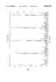
- FIG. 3is an example of an output signal from the symbol-matched filter
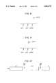
- FIG. 4is an example of an output signal from the frame-matched filter
- FIG. 5illustrates an approach to finding a correct time instant at which to measure an output of a simple-matched filter
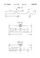
- FIG. 6illustrates a matched filter having register and adder
- FIG. 7illustrates a frequency response curve demonstrating that sampling may not occur at a chip peak
- FIGS. 8 and 9illustrate selection of the correct time to yield the largest output
- FIG. 10illustrates an example of packets for time division duplex
- FIG. 11illustrates switch time
- FIGS. 12-20illustrate frequency division duplex examples
- FIG. 21illustrates adder gates
- FIG. 22illustrates a remote unit handing off between two base stations
- FIG. 23is a block diagram of the remote unit.
- the present inventionprovides a new and novel system and method for handing off a remote unit between two base stations.
- the inventionis taught, by way of example, for handing off a remote unit from a first base station transmitting a first received-spread-spectrum signal to the remote unit, to a second base station transmitting a second received-spread-spectrum signal to the remote unit.
- a received-spread-spectrum signalmay include a plurality of packets.
- Continuous, non-packeted spread-spectrum signalsalso may be used with the handoff method and apparatus.
- a header type of sequencewould have to occur periodically in the continuous spread-spectrum signal, from which timing may be triggered.
- the latter embodimentmight be referred to as a data block with a header, and is equivalent to the packet with header as discussed herein.
- the discussionrefers to the packet and header, with the understanding that other embodiments are equivalent.
- Each packethas a header followed in time by data.
- the headeris generated from spread-spectrum processing, by using techniques well known in the art, a header-symbol-sequence signal with a chip-sequence signal.
- the header-symbol-sequence signalis a predefined sequence of symbols.
- the header-symbol-sequence signalmay be a constant value, i.e., just a series of 1-bits or symbols, or a series of 0-bits or symbols, or alternating 1-bits and 0-bits or alternating symbols, a pseudorandom symbol sequence, or other predefined sequence as desired.
- the chip-sequence signalis user defined and, in a usual practice, is used with a header-symbol-sequence signal.
- the headerindicates the start of data, aids in acquisition and reacquisition, and helps provide phase reference between multipaths for diversity combining such as in time diversity systems, sometimes referred to as RAKE systems.
- the data part of the spread-spectrum packetis generated similarly, from techniques well known in the art as used for the header, by spread-spectrum processing a data-symbol-sequence signal with the chip-sequence signal.
- the data-symbol-sequence signalmay be derived from data, or an analog signal converted to data, signalling information, or other source of data symbols or bits.
- the chip-sequence signalcan be user defined, and preferably is nearly orthogonal to other spread-spectrum channels using the chip-sequence signal, as is well known in the art.
- the matched filter embodimentis discussed initially, followed by a discussion on the handoff method and apparatus.
- the spread-spectrum-matched filter apparatusincludes code means, symbol-matched means, frame-matched means, control means, and demodulator means.
- the control meansis coupled to the code means and symbol-matched means.
- the frame-matched meansis coupled to the output of the symbol-matched means.
- the demodulator meansis coupled to the output of the symbol-matched means.
- the code meansgenerates a replica of the chip-sequence signal.
- the replica of the chip-sequence signalis the same sequence as used for generating, at a spread-spectrum transmitter, the received-spread-spectrum signal which arrives at the input of the spread-spectrum-matched-filter apparatus.
- the code meanscan change, over time, the particular chipping sequence from which the replica of the chip-sequence signal is generated. Accordingly, the spread-spectrum-matched-filter apparatus can be used for a variety of chip-sequence signals as generated by the code means, as might be used in a cellular-spread-spectrum architecture where a receiver might move from one geographical area to another. As the spread-spectrum-matched-filter apparatus moves from one geographical area to another, by way of example, a requirement might be imposed to change the chip-sequence signal in each of the different geographical areas. Similarly, each transmitter within the geographical area of a base station may have a different chip-code sequence.
- the symbol-matched meanshas a symbol-impulse response.
- symbolis used to denote those means or components which operate to detect or process a data or header symbol from the received-spread-spectrum signal.
- the symbol-impulse responsecan be set from the replica of the chip-sequence signal generated by the code means. Thus, the symbol-impulse response may be set for filtering from the received-spread-spectrum signal, the header and the data-symbol-sequence signal.
- the symbol-matched meansWith the symbol-impulse response set to the replica of the chip-sequence signal, and with the header portion of the received-spread-spectrum-signal being present at the receiver, the symbol-matched means outputs a despread-header-symbol-sequence signal. Upon detecting the despread-header-symbol sequence, the frame-matched means outputs a high level signal which may be used as a start-data signal. Other uses may be to synchronize the sequence of transmit, switching and receive cycles or to generate a timing signal for any other event that is related in time to the header.
- the symbol-matched meanscontinues to have the symbol-impulse response set from the replica of the chip-sequence signal.
- the symbol-matched meansfilters the received-spread-spectrum signal. Timing to sample the data portion of the received-spread-spectrum signal is triggered from the start-data signal.
- the symbol-matched meansoutputs the despread-data-symbol-sequence signal. Accordingly, the symbol-matched means can despread the header and the data portion of the received-spread-spectrum signal.
- the frame-matched meanshas a frame-impulse response matched to the header-symbol-sequence signal.
- the frame-matched meansfilters the despread-header-symbol-sequence signal from the symbol-matched means, and generates as a result thereof, a start-data signal when the despread-header-symbol-sequence signal matches the frame-impulse response.
- the frame-matched meansmay be programmable, i.e., have a programmable frame-impulse response, which might change between different geographical areas.
- the control meanscontrols the setting of the symbol-impulse response of the symbol-matched means.
- the control meanscan dynamically set the symbol-matched means, by using the replica of the chip-sequence signal generated by the code means, to match the chip-sequence signal embedded in the received-spread-spectrum signal.
- the symbol-matched meansmay include an in-phase-symbol-matched means and a quadrature-phase-symbol-matched means.
- the in-phase-symbol-matched meanshas an in-phase-symbol-impulse response which can be set from the replica of the chip-sequence signal generated by the code means.
- the in-phase-symbol-matched meansdespreads from the received-spread-spectrum signal, an in-phase-component of the header portion of the packet as a despread-in-phase-component of the header-symbol-sequence signal, or an in-phase component of the data portion of the packet as a despread-in-phase component of the data-symbol-sequence signal.
- the quadrature-phase-symbol-matched meanshas a quadrature-impulse response which can be set from the replica of the chip-sequence signal generated by the code means.
- the quadrature-phase-symbol-matched meansdespreads from the received-spread-spectrum signal a quadrature-phase component of the header portion of the packet as a despread-quadrature-phase component of the header-symbol-sequence signal.
- the quadrature-phase-symbol-matched meanswhen the quadrature-phase-symbol-matched means has the quadrature-symbol-impulse response set from the replica of the chip-sequence signal, the quadrature-phase-symbol-matched means despreads the received-spread-spectrum signal as a quadrature-component of the data portion of the packet as a despread-quadrature-phase component of the data-symbol-sequence.
- control meanssets the in-phase-symbol-matched means and the quadrature-phase-symbol-matched means matched to detect the chip-sequence signal.
- the in-phase-symbol-matched means and the quadrature-phase-symbol-matched meansare matched simultaneously, and preferably are matched to the same chip-sequence signal.
- the frame-matched meansmay include an in-phase-frame-matched means and a quadrature-phase-frame-matched means.
- the in-phase-frame-matched meanshas an in-phase-frame-impulse response matched to an in-phase component of the header-symbol-sequence signal.
- an in-phase-start-data signalis generated.
- the quadrature-phase-frame-matched meanshas a quadrature-phase-frame-impulse response matched to a quadrature-phase component of the header-symbol-sequence signal.
- a quadrature-phase-start-data signalis generated.
- the in-phase-start-data signal and the quadrature-phase-start-data signalare generated simultaneously, buy they may also occur at different times.
- the in-phase-start-data signal and the quadrature-phasestart data signalare combined as the start-data signal.
- Timing for sampling the output of the in-phase-symbol-matched means and the quadrature-phase-symbol-matched means for detecting the data-symbol-sequence signalis triggered, at a time delay, from the start-data signal.
- the time delaymay be zero.
- the code meansis embodied as a code generator 43
- the symbol-matched meansis embodied as an in-phase-symbol-matched filter 35 and a quadrature-phase symbol-matched filter 37
- the frame-matched meansis embodied as an in-phase-frame-matched filter 38 and a quadrature-phase-frame-matched filter 39
- the control meansis embodied as a controller 46
- the demodulator meansis embodied as a demodulator 41.
- the in-phase-symbol-matched filter 35 and the quadrature-phase-symbol-matched filter 37may be constructed as digital-matched filters, surface-acoustic-wave devices, or as software embedded in a processor or as an application specific integrated circuit (ASIC). Also shown is a voltage-controlled oscillator 45, timing generator 44, diversity combiner 42, frame processor 40, Costas loop 36 or other generic tracking loop, in-phase analog-to-digital converter 33, quadrature-phase analog-to-digital converter 34, in-phase mixer 31, and quadrature-phase mixer 32.
- ASICapplication specific integrated circuit
- the in-phase analog-to-digital converter 33is coupled between in-phase mixer 31 and in-phase-symbol-matched filter 35.
- the quadrature-phase analog-to-digital converter 34is coupled between the quadrature-phase mixer 32 and the quadrature-phase-symbol-matched filter 37.
- the Costas loop 36is coupled to the output of the in-phase-symbol-matched filter 35, to the output of the quadrature-phase-symbol-matched filter 37, and to the in-phase mixer 31 and the quadrature-phase mixer 32.
- the in-phase-frame-matched filter 38is coupled between the in-phase-symbol-matched filter 35 and the frame processor 40 and the demodulator 41.
- the quadrature-phase-frame-matched filter 39is coupled between the quadrature-phase-symbol-matched filter 37 and the processor 40 and the demodulator 41.
- the code generator 43is coupled between the timing generator 44 and the in-phase-symbol-matched filter 35 and the quadrature-phase-frame-matched filter 37.
- the timing control circuitcontrols the sampling instant of the analog-to-digital converter timing generator 44 to the in-phase-symbol-matched filter 35 and the quadrature-phase-symbol-matched filter 37.
- the voltage-controlled oscillator 45is coupled to the timing generator 44 and to the matched-filter controller 46.
- the diversity combiner 42is coupled to the frame processor 40 and the demodulator 41.
- the controller 46is coupled to the frame processor 40.
- the prefixes "in-phase” and "quadrature-phase”denote that component, i.e., in-phase or quadrature-phase, of the received-spread-spectrum signal, with which the element operates.
- the in-phase analog-to-digital converter 33 and the quadrature-phase analog-to-digital converter 34may be embodied as a hard limiter which performs one-bit analog-to-digital conversion, or as an N-bit analog-to-digital converter. Analog-to-digital converters are well known in the art.
- the controller 46is coupled to the diversity combiner 42, the frame-matched filter 38, the frame-matched filter 39, the demodulator 41, the timing generator 44, the code generator 43, the in-phase-analog-to-digital converter 33, and the quadrature-phase-analog-to-digital converter 34.
- the diversity combiner 42may only process one signal.
- a received-spread-spectrum signal at the signal inputis translated to an intermediate frequency or baseband frequency by in-phase mixer 31 and quadrature-phase mixer 32.
- the received-spread-spectrum signalis assumed to be translated to a baseband frequency.
- the portion of the spread-spectrum receiverwhich includes low noise amplifiers, automatic-gain-control (AGC) circuits, filters, etc., is well known in the art, and therefore, is not shown.
- the baseband received-spread-spectrum signalis converted to a digital signal by in-phase analog-to-digital converter 33 and quadrature-phase analog-to-digital converter 34.
- AGCautomatic-gain-control
- the in-phase-symbol-matched filter 35has an in-phase-symbol-impulse response which is set by the replica of the chip-sequence signal from code generator 43.
- the in-phase-symbol-matched filter 35can despread the received-spread-spectrum signal as a despread-in-phase component of the header-symbol-sequence signal or as a despread-in-phase component of the spread-spectrum-processed data-symbol-sequence signal.
- the in-phase-symbol-matched filter 35outputs either a despread-in-phase component of the header-symbol-sequence signal, or a despread-in-phase component of the spread-spectrum-processed data-symbol-sequence signal as a despread-in-phase-data-symbol-sequence signal.
- the quadrature-phase-symbol-matched filter 37has a symbol-impulse response which can be set by the replica of the chip-sequence signal generated by the code generator 43.
- the quadrature-phase-symbol-matched filter 37despreads the received-spread-spectrum signal as a quadrature-phase component of the header-symbol-sequence signal or as a quadrature-phase component of the spread-spectrum-processed data-symbol-sequence signal.
- the output of the quadrature-phase-symbol-matched filter 37is either a despread-quadrature-phase component of the header-symbol-sequence signal or a despread-quadrature-phase component of the spread-spectrum-processed data-symbol-sequence signal as a despread-quadrature-phase-data-symbol-sequence signal.
- the in-phase-symbol-matched filter 35 and the quadrature-phase-symbol-matched filter 37are ultimately controlled by the controller 46.
- the controller 46controls timing and determines at desired timings when the code generator 43 sets the symbol-impulse responses of the in-phase-symbol-matched filter 35 and the quadrature-phase-symbol-matched filter 37 to the respective chip-sequence signal being used in a particular geographic area.
- the controller 46controls the in-phase signal register 51 and the quadrature-phase signal register 52, which correspond to the in-phase-symbol-matched filter 35 and the quadrature-phase-symbol-matched filter 37, respectively.
- the Costas loop 36uses the output from the in-phase-symbol-matched filter 35 and the output from the quadrature-phase-symbol-matched filter 37 to generate the cosine signal and sine signal for in-phase mixer 31 and quadrature-phase mixer 32, respectively.
- the spread-spectrum receiverreceives packets of header and data, which may arrive as a stream of uninterrupted packets in a frequency division duplex (FDD) application, or as separate packets in a time division duplex (TDD) application.
- FDDfrequency division duplex
- TDDtime division duplex
- the despread and detected headerprovides timing and synchronization for data within a respective packet.
- the outputis a despread-header-symbol-sequence signal.
- An example of a signal outputted as a despread-header-symbol-sequence signalis illustrated in FIG. 3.
- the despread-header-symbol-sequence signalis passed through in-phase-frame-matched filter 38 and quadrature-phase-frame-matched filter 39.
- the in-phase-frame-matched filter 38has an in-phase-frame-impulse response matched to the in-phase component of the header-symbol-sequence signal, and accordingly, generates an in-phase-start-data signal when the in-phase component of the despread-header-symbol-sequence signal matches the in-phase-frame-impulse response.
- the quadrature-phase-frame-matched filter 39has a quadrature-phase-frame-impulse response matched to a quadrature-phase component of the header-symbol-sequence signal.
- the quadrature-phase-frame-matched filter 37When the despread-header-symbol-sequence signal from the quadrature-phase-symbol-matched filter 37 matches the quadrature-phase-frame-impulse response of the quadrature-phase-matched filter 37, then the quadrature-phase-frame-matched filter outputs a quadrature-phase-start-data signal.
- An example of a signal outputted from the frame-matched filteris illustrated in FIG. 4.
- the large spike's, i.e., large signal levels,are the start-data signal referred to herein. These spikes or start-data signals serve as timing references to synchronize timing, as disclosed herein.
- the in-phase-start-data signal and the quadrature-phase-start-data signalare demodulated by demodulator 41, and can be used as an initial timing signal for controlling when the diversity combiner 42 combines the output from the demodulator 41 for the respective signals from in-phase-symbol-matched filter 35 and the quadrature-phase-symbol-matched filter 37.
- the in-phase-start-data signal and the quadrature-phase-start-data signalcan be processed by frame processor 40 to trigger a timing signal, i.e., the start-data signal, to the controller 46 which actuates the timing for when to sample the outputs of the in-phase-symbol-matched filter 35 and the quadrature-phase-symbol-matched filter 37, for detecting the data-symbol-sequence signal.
- a timing signali.e., the start-data signal
- the in-phase-symbol-matched filter 35 and the quadrature-phase-symbol-matched filter 37have their respective in-phase-symbol-impulse response and quadrature-phase-symbol-impulse response determined, under the control of the controller 46, such that they are matched to the chip-sequence signal within 6.4 microseconds (64 chips at 10 Mchips/sec).
- current designshave these respective symbol-matched filters loaded within 12.8 microseconds, for a system operating at 100 MHz, with each of the in-phase-symbol-matched filter 35 and the quadrature-phase-symbol-matched filter 37 having a 256 stage shift register (256 chips at 20 Mchips/sec).
- the demodulator 41can be implemented using coherent demodulation, or alternatively using noncoherent demodulation.
- the diversity combiner 42combines in a variety of ways, such as maximum likelihood, straight combining, addition, or the demodulated outputs from the in-phase-symbol-matched filter 35 and the quadrature-phase-symbol-matched filter 37 as demodulated through demodulator 41.
- FIG. 2illustrates the matched filter using the time sharing of the multiplier array and adder tree. Shown in FIG. 2 are in-phase-signal register 51, quadrature-phase-signal register 52, reference-signal register 53, multiplier array 54, adder tree 55, data register 56, and controller 46. As shown, the dotted lines indicate that the controller 46 provides the necessary controlling of the in-phase-signal register 51, the quadrature-phase-signal register 52, the reference-signal reference 53 and the data register 56. The solid lines indicate the signal flow from the in-phase-signal register 51, the quadrature-phase-signal register 52, the reference-signal register 53 through the multiplexer 57. The in-phase-signal register 51 and the quadrature-phase-signal register 52 are coupled through multiplexer 57 to multiplier array 54 to adder tree 55 to data register 56. The data register 56 has an in-phase output and quadrature-phase output.
- the present inventionalso includes a method which uses a symbol-matched filter and a frame-matched filter with a spread-spectrum receiver on a received-spread-spectrum signal.
- the received-spread-spectrumis assumed to have a plurality of packets, with each packet including a header and data portion.
- the headeris generated from spread-spectrum processing a header-symbol-sequence signal with a chip-sequence signal.
- the data portion of the packetis generated from spread-spectrum processing a data-symbol-sequence signal with the chip-sequence signal.
- the methodcomprises the steps of generating a replica of the chip-sequence signal.
- the methodprograms the symbol-matched filter with the replica of the chip-sequence signal to set the symbol-matched filter to have a symbol-impulse response matched to the chip-sequence signal.
- the methoddespreads the header portion of the packet from the received-spread-spectrum signal as a despread header-symbol-sequence signal.
- the frame-matched filterhas a frame-impulse response matched to the header-symbol-sequence signal.
- the methodtherefore uses the frame-matched filter to filter the despread header-symbol-sequence signal.
- the methodthereafter generates from the filtered despread-header-symbol-sequence signal, the data-start signal in response to the despread-header-symbol-sequence signal matching the frame-impulse response of the frame-matched filter.
- the methodalso generates at a time delay from the data-start signal, a data-control signal.
- the time delaymay be zero.
- the methodprograms the frame-matched filter with the replica of the data-chip-sequence signal so that the frame-matched filter has the frame-impulse response matched to the data-symbol-sequence signal.
- the methodthereby despreads, while the frame-matched filter is matched to the data-symbol-sequence signal, the data-spread-spectrum channel from the received-spread-spectrum signal as a despread-data-symbol-sequence signal.
- the method as described hereinmay be extended to in-phase and quadrature-phase components of a received-spread-spectrum signal.
- the methodwould have the step of despreading the header portion of the packet from the received-spread-spectrum signal including the steps of despreading, from the received-spread-spectrum signal, the in-phase component of the header as a despread in-phase component of the header-symbol-sequence signal, and despreading, from the received-spread-spectrum signal, the quadrature-phase component of the header as a despread-quadrature-phase component of the header-symbol-sequence signal.
- the in-phase component and the quadrature-phase component of the received-spread-spectrum signalcan be despread as in-phase components and quadrature-phase components of the data-symbol-sequence signal.
- the methodwould include despreading, from the received-spread-spectrum signal, an in-phase component of the data portion of the packet as a despread-in-phase component of the data-symbol-sequence signal.
- the methodwould also include despreading a quadrature-phase component of the data portion of the packet as a despread-quadrature-phase component of the data-symbol-sequence signal.
- the methodcan also include generating an in-phase-start-data signal and a quadrature-phase-start-data signal, in response to the in-phase component and the quadrature-phase component of the despread header-symbol-sequence signal matching the in-phase-frame-impulse response and the quadrature-phase-frame-impulse response, respectively.
- the in-phase-symbol-matched filter 35 and the quadrature-phase-symbol-matched filter 37are loaded with M local sequence symbols, i.e., the replica of the chip-sequence signal.
- This large outputdoes not require that a synchronization process be successfully completed a priori or that additional circuits dedicated to the acquisition process be employed and it achieves code synchronization in the shortest possible time to acquire the incoming spreading chip-sequence signal.
- Thishas the advantage of lower implementation cost, lower physical volume, reduced power consumption, more rapid implementation and much better performance as measured by the time required to achieve code synchronization.
- the presence of a strong signal level outputindicates that at that specific moment in time M incoming signal symbols and the M symbols of the local spreading code, i.e., chip-sequence signal, loaded in the in-phase-symbol-matched filter 35 and the quadrature-phase-symbol-matched filter 37 are in alignment.
- M incoming signal symbols and the M symbols of the local spreading codei.e., chip-sequence signal
- the in-phase-symbol-matched filter 35 and the quadrature-phase-symbol-matched filter 37be fully loaded with the next M symbols of the local spreading code, i.e., the chip-sequence signal, at any time prior to the arrival of the next M incoming signal symbols at the in-phase-symbol-matched filter 35 and the quadrature-phase-symbol-matched filter 37.
- Mwhich denotes the size of the respective symbol-matched filter as measured in the number of signal samples, is much larger than any value on the order of one; in an example embodiment, M is on the order of 250. Because M is much larger than one of the circuits required to implement the code, phase synchronization functions are much easier to design and implement. This has the advantage of lower implementation cost, lower physical volume, reduced power consumption, more rapid implementation and inherently better performance.
- the in-phase-symbol-matched filter 35 and the quadrature-phase-symbol-matched filter 37identify, characterize and extract the information which arrives through all available channels, or paths, intrinsically, without any additional and parallel signal processing paths.
- the outputs due to the signals' propagation through different channelsare output by the in-phase-symbol-matched filter 35 and the quadrature-phase-symbol-matched filter 37 offset in time.
- the reception and separation of the signals propagating through different channelsdoes not require any additional circuits and the individual signals, which are now separate in time, can be easily individually manipulated and combined in optimum ways such that the matched filter receiver attains the performance of an L-diversity system.
- a receiver capable of identifying, separating and combining large numbers (L) of signal replicas propagating through different channelsis a time diversity receiver and is commonly called a RAKE receiver.
- the RAKE receiver structurecan be implemented using the matched filter without the excessive complexity incurred by alternative system implementations.
- the in-phase-symbol-matched filter 35 and the quadrature-phase-symbol-matched filter 37 implementation at the heart of the diversity processing systemhas the advantage of lower implementation cost, lower physical volume, reduced power consumption, more rapid implementation, less complex control and better performance.
- the symbol-matched-filter-based demodulator as described hereinutilizes only one such set of circuits and, using information which is intrinsically generated, can then coherently demodulate any number of signal replicas that arrive via separate propagation paths.
- the mechanism by which this is accomplishedis to employ one conventional phase tracking circuit, e.g., phase-locked loop (PLLs), Costas loop, or n th power loop, in order to establish a temporarily stable phase reference and to then extract the phase offset of each individual signal with respect to that phase reference.
- the incoming signalis first downconverted non-coherently to some frequency, including the 0 Hz frequency (DC).
- the in-phase and quadrature-phase channel outputsare read from the in-phase-symbol-matched filter 35 and the quadrature-phase-symbol-matched filter 37, respectively.
- the phase offset of the carrier signalis contained in the relative amplitudes of the in-phase and quadrature-phase outputs which are then used directly to demodulate the received data signal.
- the phase estimate on the individual propagation pathscan be improved by further matched filtering to demodulate the signal with performance equal to or better than that obtained using conventional coherent demodulators but without the added complexity introduced by conventional coherent demodulators. Therefore the symbol-matched filter-based implementation has the advantage of much lower complexity, lower implementation cost, lower physical volume, reduced power consumption, more rapid implementation and better performance.
- a set of multipliers and the associated adder treemay be eliminated.
- each multiplexermay serve to connect to the multiplier/adder tree structure either the in-phase or quadrature-phase signal registers.
- This implementationadds the complexity of two multiplexers and reduces the complexity associated with a set of multipliers and an adder tree for a significant net reduction in complexity.
- the symbol-matched filteris a digital signal processor, the output of which is of interest only at that instant in time when the portion of interest of the incoming signal is fully loaded and is of no interest at any other time.
- the size of the symbol-matched filtersis approximately 64 or 256 stages, requiring 64 or 256 clock cycles, respectively, to load the input samples of the received-spread-spectrum signal.
- the output of the symbol-matched filteris of interest only for one or two clock cycles and is of no interest for the rest of the approximately 248 clock cycles. Thus the circuit can be reused during these 248 clock cycles.
- the symbol-matched filtersare loaded with the reference corresponding to the first signal.
- the output due to the first signaloccur during the 50 th and 51 st clock cycle.
- the symbol-matched filtersare loaded with the reference corresponding to the third signal.
- the output to the third signalwill occur during the 150 th and 151 st clock cycle.
- the symbol-matched filtersare loaded with the reference corresponding to the fifth signal.
- the output due to the fifth signalwill occur during the 250 th and 251 st clock cycle.
- the cyclethen repeats itself for the next output due to the first, second, third, fourth and fifth signals using only one matched filter.
- the complexity and size of implementationis reduced by 80% while the signal processing benefits remain constant.
- the matched filteris preferred since it can provide significantly faster acquisition than the standard serial-search technique. For example, if the chip rate were f c and the number of chips that must be searched before accepting or discarding a hypothesis is N and the code length is L, then the "worst-case" acquisition time for serial search is LN/f c while the equivalent matched-filter acquisition time is Lf c .
- Nis between 1000 and 10,000, so that for a matched filter of length N, a significant savings can accrue by using a matched filter.
- One aspect of this inventionis a novel procedure to implement the matched filter.
- Another aspect of this inventionis to not employ a transmitted reference but to achieve "coherent" detection by employing frequency locked and phase locked circuits which do not require a large number of gates.
- the matched filter of the present inventionis divided into two or more matched filter sections.
- the present inventionemploys two sections.
- the symbol-matched filteris 256 chips long and the frame-matched filter is 32 chips long.
- the size of the symbol-matched filterdetermines the number of simultaneous users. It has been found experimentally that the number of simultaneous signals in the DS-CDMA system is approximately N s /2, when using the cascaded matched filter approach diagrammed in FIGS. 1 and 2.
- the symbol-matched filter outputis noisy and a casual observation does not indicate the instant at which a match occurs when there are many signals present simultaneously. This is illustrated in FIG. 3.
- the preferred approach to finding the correct time instantis to measure all 256 symbol-matched filter outputs and record the largest. This procedure is then repeated until a given K number of measurements indicate the same instant, as illustrated in FIG. 5.
- time slot JAfter time slot J is selected, the choice is verified using the frame-matched filter.
- a preferred approachis to sample once per chip.
- the sampling rateis f c .
- the problem with this approachis that the sampling may not occur at the peak of a chip, as illustrated in FIG. 7. This problem is compounded by the fact that the local receiving chip-clock crystal might differ slightly from the chip-clock crystal in the transmitter. As a result of clock mismatch, the sampling instant slides across the chip.
- one aspect of this inventionis to ensure that the sampling clock continually samples at or near the peak of each chip.
- Second the present inventionaverages the outputs of the symbol-matched filter N F times, delays the chip clock by a fraction of a chip, preferably 1/8 chip, and averages the output of the symbol-matched filter, N F times. Then the chip clock is advanced by 1/8 chip and again the symbol-matched filter output is averaged N F times. The timing selected is that which yields the largest output. This process is continually repeated, as illustrated in FIG. 8 and 9.
- the transmitter and receiver RF crystal frequenciesusually differ. Differences of 20 kHz are possible.
- the incoming signalundergoes a Doppler shift due to the fact that the transmitter and/or receiver may be in motion.
- the Doppler shiftusually is not larger than 300 Hz at a center frequency of 2 GHz.
- time-division duplexTDD
- frequency-division duplexFDD
- the time-division duplexcan be used for the CP ASIC.
- the frequency-division duplexcan be used for the WLL and PCS ASIC since higher data rates are needed for WLL and PCS applications. Using time-division duplex effectively doubles the data rate.
- FIG. 10illustrates an example of packets for time division duplex.
- Dead timeis used for switching from transmit (TX) mode to receive (RCVE) mode, and vice versa as illustrated in FIG. 11.
- f c10.368 MHz (required by adaptive delta pulse code modulation (ADPCM)).
- ADPCMadaptive delta pulse code modulation
- the receive packet durationis equal to the transmit packet duration.
- the switch (SW) times, FIG. 11,are needed to switch the RF from the TX mode to the RCVE mode and vice versa. Approximately 50 microseconds is needed.
- An embodiment of the present inventionuses 8 symbols.
- FDD packetAn example of a FDD packet is
- Each framecontains 32 symbols: Header
- phase varies due to Doppler or oscillator offsetthen if the phase variation were small between adjacent bits, differential demodulation can be used.
- b(t)can represent the differentially decoded data stream. Differential encoding must be used. If there were no phase variation, then b(t) has twice the error of d(t); see Taub and Schilling, PRINCIPLES OF COMMUNICATION SYSTEMS.
- frequency and phaseare locked to the best of ability, and differential decoding is used to compensate for estimation inaccuracies. If the frequency locking were perfect so that the phase were consistent, then coherent detection occurs and the error rate increases by a factor of two.
- 1 bitis equal to 2 or more symbols. In that case the symbols are added prior to differential decoding. High data rates use less than 1 symbol.
- a userIn a cellular system a user, when receiving beyond the cell border, experiences a loss in signal-to-noise ratio, which results in increased errors and reduced signal quality of transmission.
- cellular type systemsemploy handoff where the user communicates first with the first base station and then with a second base station whose received power is stronger.
- Handoff algorithmsrequire the remote unit and/or the base station communicating with the remote unit, to monitor the signal quality and, if it is degraded excessively, to request handoff to another base station.
- qualitymay be measured by reading the symbol-matched filter voltage level. For example, a 256-stage symbol-matched filter would read 256 if there were no errors, 254 with 1 chip in error, etc.
- the remote unitcan, with a single matched filter, by multiplexing its duties, use the single matched filter for in-phase and quadrature-phase communications with the first base station and for in-phase and quadrature-phase scanning of the other adjacent cells, typically six.
- One signal from each base stationis used for handoff and uses a known code. This is analogous to AMPS where a specified frequency band is always used for handoff implementation.
- the present inventionprovides a spread-spectrum-communication system for a remote unit handing-off between two base stations.
- the systemincludes a central control unit 63, a plurality of base stations 61, 62, and a remote unit 60; there may be a plurality of remote units.
- the remote unittransmits data to a first base station 61 of the plurality of base stations at a first data rate and a first power level, and then hands off from the first base station to a second base station 62, through the central control unit 63, in response to signal quality monitoring and comparison.
- the remote unitincludes transmitting means, receiving means, monitoring means, first memory means, selecting means, comparison means, and processor means.
- the processor meansis coupled between the transmitting means and the comparison means.
- the monitoring meansis coupled between the receiving means and the comparison means.
- the selecting meansis coupled between the first memory means and the comparison means.
- the first memory meansis coupled to the receiving means.
- the second memory meansis coupled to the processor means.
- a single memory meansmay be sufficient in which case the single memory means is coupled to the receiving means and to the processor means.
- the systemmay further comprise code generating means, coupled to the receiving means.
- the receiving meanstypically includes matched means.
- the transmitting meansis for transmitting data from the remote unit to the first base station at a first data rate and a first power level.
- Receiving meansis for receiving a plurality of received-spread-spectrum signals radiated from the plurality of base stations.
- Matched means having a first chip codeis for despreading a first received-spread-spectrum signal.
- Monitoring meanscoupled to the output of the matched means, is for monitoring a first signal quality of the first received-spread-spectrum signal.
- First memory meanscoupled to said receiving means, is for storing a plurality of signal qualities for the plurality of received-spread-spectrum signals, respectively.
- Selecting meanscoupled to the first memory means, is for selecting, from-the plurality of received-spread-spectrum signals, a second received-spread-spectrum signal having a second signal quality.
- the second received-spread-spectrum signalis transmitted from a second base station of the plurality of base stations.
- the second received-spread-spectrum signalis selected using the plurality of signal qualities stored in the first memory means. Selection may be based upon a comparison of power level, signal-to-noise ratio, or probability of error.
- Comparison meanscoupled to the monitoring means and to the selecting means, is for comparing the first signal quality to at least one of a predetermined threshold and the second signal quality.
- the comparison meansmay compare the first signal quality to both a predetermined threshold and the second signal quality.
- Processor meansresponsive to the first signal quality falling below any of the predetermined threshold and the second signal quality, or both, initiates handoff to the second base station and queues data for transmission.
- Second memory meansresponsive to handoff initiation, stores the data queued for transmission.
- Processor meanscompletes handoff to the second base station and directs the matched means to despread, using a second chip code, the second received-spread-spectrum signal. In response to handoff completion, transmitting means transmits the stored data to the second base station.
- the stored datais transmitted at a second data rate and a second power level, with the second data rate greater than the first data rate and with the second power level greater than the first power level.
- This increase in power level and data rateeffectively a burst transmission, transfers the stored data to the second base station allowing the remote unit to transmit both accumulated data and current data without data loss.
- receiving meansmay be embodied as a receiver 71 with matched filter.
- First memory meansmay be embodied as a memory 73.
- Monitoring meansmay be embodied as a monitoring device 72.
- Selecting meansmay be embodied as a decision device 74 coupled to the memory 73.
- Comparison meansmay be embodied as a comparator 75 coupled to the monitoring device 72 and to the decision device 74.
- Processor meansmay be embodied as a processor 76
- second memory meansmay be embodied as a processor memory 77 coupled to the processor 76.
- Transmitting meansmay be embodied as a transmitter 78 coupled to the processor 76.
- Code generating meansmay be embodied as a code generator 79 coupled to the receiver with matched filter 71 for changing a chip code of the matched filter.
- the remote unit 60is assumed to be communicating with a first base station 61 using spread-spectrum modulation.
- the remote unit 60has a matched filter, as previously discussed, for despreading a first received-spread-spectrum signal transmitted from the first base station 61.
- the remote unit 60transmits data to the first base station 61 at a first data rate and at a first power level.
- the remote unit 60receives a second received-spread-spectrum signal from the second base station 62.
- the method of the present inventionpreferably is performed in an application specific integrated circuit (ASIC), although the method also could be performed in a general purpose, digital signal processor, or in discrete electronic components.
- ASICapplication specific integrated circuit
- the remote unit 60typically transmits data at the first data rate and the first power level to the second base station 62.
- the remote 60 unitmay, however, transmit data to the second base station 62 at a data rate and/or at a power level different from the first data rate and the first power level.
- the latter casemight occur if the second base station 62, by way of example, covered a large geographical area and the remote unit 60 were in an outlying area from that base station.
- Other examplesinclude a change from voice to video transmission, or a geographical situation that includes buildings, requiring the second base station 62 to have a different data rate or power level from that of the first base station 61.
- the data ratesmay change between base stations.
- the method of the present inventionincludes the step of monitoring, at the output of the matched filter of the remote unit 60, a first signal quality of the first received-spread-spectrum signal transmitted from the first base station 61.
- first signal qualityis meant a signal quality as used for determining the quality of the signal transmitted as is known in the art. Typical parameters used for signal quality include, but are not limited to, probability of error, power level, and signal-to-noise ratio.
- the monitoring at the output of the matched filteris for determining how well the signal is being received from the first base station 61, in order to ultimately make a decision as to whether to initiate a handoff.
- the probability of error of the first received-spread-spectrum signalmay be compared to a probability of error of a second spread-spectrum signal, and a decision to handoff can be made when the probability of error of the first received-spread-spectrum signal increases or becomes greater than the probability of error of the second received-spread-spectrum signal.
- a decision to handoffcan be made when the probability of error of the first received-spread-spectrum signal increases or becomes greater than the probability of error of the second received-spread-spectrum signal.
- the power level or signal-to-noise ratio of the first received-spread-spectrum signalfalls below the power level or signal-to-noise ratio of the second received-spread-spectrum signal, then a decision can be made to initiate a handoff.
- the methodincludes the step of scanning, at the remote unit, a plurality of received-spread-spectrum signals radiated from the plurality of base stations. This step provides a method of determining which base stations are available for handoff; typically the available base stations are the neighboring base stations.
- the methodstores, at the remote unit, a plurality of signal qualities, respectively.
- the signal quality criteriasuch as probability of error, power level or signal-to-noise ratio, are measured and stored at the remote unit.
- the storingmay be accomplished in a digital memory, such as a random access memory (RAM), or other memory devices.
- the methodtypically includes the step of selecting from the plurality of received-spread-spectrum signals, using the plurality of signal qualities from the plurality of received-spread-spectrum signals, a second received-spread-spectrum signal.
- a criterionis set for selecting the second received-spread-spectrum signal from the plurality of received-spread-spectrum signals.
- this criterioncould be based on signal quality; the second received-spread-spectrum signal is that received-spread-spectrum signal having a signal quality better than the rest of the signals in the plurality of received-spread-spectrum signals.
- the remote unitcontinually scans adjacent channels and keeps a record of the received-spread-spectrum signal having, e.g., the lowest probability of error, P e and also being below a threshold.
- Each scan of the preferred base station, i.e., the second base stationis recorded and stored in memory; however, no action takes place until the quality of communication with the first base station is sufficiently degraded.
- the remote unit 60sends a request to the central control unit 63 through the first base station 61 to have the first base station 61 switch the remote unit 60 to the preferred base station, i.e., the second base station 62.
- the methodfurther includes the step of determining when the first signal quality is degraded as compared with a predetermined threshold and/or the second signal quality.
- the methodcan be based on comparing the second signal quality to the first signal quality.
- the methodmay be based on comparing the first signal quality to a threshold.
- the methodmay be based on comparing the first signal quality to the second signal quality and to a predetermined handoff threshold. In essence, this could be based on a maximum likelihood receiver, or a simple threshold device, or other techniques for choosing when to initiate a handoff.
- handoff to the second base stationwould be initiated when the second received-spread-spectrum signal has a lower probability of error than the first received-spread-spectrum signal.
- handoffwould be initiated when the second received-spread-spectrum signal has a higher signal-to-noise ratio or greater power level, respectively, than does the first received-spread-spectrum signal.
- the remote unitwhen the remote unit determines it is time for a handoff, the remote unit initiates handoff to the second base station 62.
- a requestis sent from the remote unit 60 to the first base station 61, and from the first base station 61 to a central control unit 63.
- the central control unit 63is common to the first base station 61 and the second base station 62.
- the methodincludes queuing and storing, at the remote unit, the data that would have been transmitted to the first base station 61 during the handoff period.
- the storing steptypically, although not necessarily, cuts off data transmission during handoff, and the data that would normally be transmitted during the handoff is queued, stored and then transmitted at a later point in time.
- the remote unit 60could also receive transmissions from both the first base station 61 and the second base station 62 during this transmit period and then either combine them or use the best quality signal.
- the next stepis to complete handoff to the second base station 62.
- the remote unit 60synchronizes to the second received-spread-spectrum signal.
- the data that was stored during the handoff periodis transmitted to the second base station 62.
- the time for this handoffmight be on the order of milliseconds, thus the stored data would typically not be voluminous.
- the methodtransmits the stored data from the remote unit 60 to the second base station 62 at a second data rate.
- the second data rateis typically a higher or faster rate than the first data rate.
- the methodmay include transmitting to the second base station 62 the stored data at a second power level.
- the second data rate and the second power levelmight be twice the first data rate and the first power level, respectively.
- One way to accomplish this increase in channel capacityis to increase the power level. Since the stored data is transmitted for a short period of time, such as a few microseconds or even a few seconds, the transmission at the higher data rate and power level would be for a short duration of time and thus would not significantly interfere with other remote units.
- the remote unit 60continues transmitting at a preferred data rate which typically might be the normal data rate and normal power level of the second base station 62.
- a preferred data ratetypically might be the normal data rate and normal power level of the second base station 62.
- the normal data rate and normal power level of the second base stationmight equal the first data rate and the first power level.
- the second data rateis a temporary data rate for transmitting the stored data to the second base station 62; once the stored data is transmitted, the remote unit 60 continues transmitting at its normal data rate.
Landscapes
- Engineering & Computer Science (AREA)
- Computer Networks & Wireless Communication (AREA)
- Signal Processing (AREA)
- Mobile Radio Communication Systems (AREA)
Abstract
Description
______________________________________15 symbols = header which is detected by a 15-stage frame-matched filter1-2 symbols = APC1-2 symbols = signaling32 symbols = voice (assuming 32 kb/s is used)1 symbols = do not care, used to compensate for propagation delay21 symbols =CRC 73 symbols______________________________________
______________________________________Timing______________________________________ 73symbols TX 73 symbols RCVE 8SW 8 SW 162 symbols/frame______________________________________
______________________________________Let 1 bit = 3 symbols240 symbols of data, sig & APC/frame symbols of header______________________________________ 32 267 + 52CRC 324 total______________________________________
______________________________________Let 1 bit = 2 symbols______________________________________ 288 + 32 320 + 4CRC symbols 324______________________________________
______________________________________Let 1 bit = 1 symbol______________________________________ 272 + 32 304 + 20CRC symbols 324______________________________________
______________________________________Let 1 bit = 1/2 symbol______________________________________ 264 + 32 296 + 28CRC symbols 324______________________________________
______________________________________Let 1 bit = 1/4 symbol______________________________________ 156 + 32 188 + 136CRC symbols 324______________________________________
______________________________________Let 1 bit = 1/8 symbol______________________________________ 154 + 32 186 +138CRC symbols 324______________________________________
______________________________________Let 1 bit = 1/8 symbol______________________________________ 194 + 32 226 + 98CRC symbols 324______________________________________
______________________________________Let 1 bit = 1/16 symbol______________________________________ 193 + 32 225 + 99CRC symbols 324______________________________________
______________________________________Let 1 bit = 1/32 symbol______________________________________ 256 32 + 0.5 288.5 + 35.5CRC symbols 324______________________________________
Claims (15)
Priority Applications (4)
| Application Number | Priority Date | Filing Date | Title |
|---|---|---|---|
| US08/638,394US5864578A (en) | 1996-04-29 | 1996-04-29 | Matched filter-based handoff method and apparatus |
| US09/181,724US6215811B1 (en) | 1996-04-29 | 1998-10-29 | Store and dump, spread-spectrum handoff |
| US09/273,507US6324207B1 (en) | 1996-04-29 | 1999-03-22 | Handoff with closed-loop power control |
| US09/789,958US7020184B2 (en) | 1996-04-29 | 2001-02-22 | Store and forward handoff |
Applications Claiming Priority (1)
| Application Number | Priority Date | Filing Date | Title |
|---|---|---|---|
| US08/638,394US5864578A (en) | 1996-04-29 | 1996-04-29 | Matched filter-based handoff method and apparatus |
Related Child Applications (2)
| Application Number | Title | Priority Date | Filing Date |
|---|---|---|---|
| US09/181,724ContinuationUS6215811B1 (en) | 1996-04-29 | 1998-10-29 | Store and dump, spread-spectrum handoff |
| US09/789,958ContinuationUS7020184B2 (en) | 1996-04-29 | 2001-02-22 | Store and forward handoff |
Publications (1)
| Publication Number | Publication Date |
|---|---|
| US5864578Atrue US5864578A (en) | 1999-01-26 |
Family
ID=24559852
Family Applications (3)
| Application Number | Title | Priority Date | Filing Date |
|---|---|---|---|
| US08/638,394Expired - Fee RelatedUS5864578A (en) | 1996-04-29 | 1996-04-29 | Matched filter-based handoff method and apparatus |
| US09/181,724Expired - Fee RelatedUS6215811B1 (en) | 1996-04-29 | 1998-10-29 | Store and dump, spread-spectrum handoff |
| US09/789,958Expired - Fee RelatedUS7020184B2 (en) | 1996-04-29 | 2001-02-22 | Store and forward handoff |
Family Applications After (2)
| Application Number | Title | Priority Date | Filing Date |
|---|---|---|---|
| US09/181,724Expired - Fee RelatedUS6215811B1 (en) | 1996-04-29 | 1998-10-29 | Store and dump, spread-spectrum handoff |
| US09/789,958Expired - Fee RelatedUS7020184B2 (en) | 1996-04-29 | 2001-02-22 | Store and forward handoff |
Country Status (1)
| Country | Link |
|---|---|
| US (3) | US5864578A (en) |
Cited By (34)
| Publication number | Priority date | Publication date | Assignee | Title |
|---|---|---|---|---|
| US6018662A (en)* | 1998-09-08 | 2000-01-25 | Nortel Networks Corporation | Method for performing progressive soft handoff in CDMA systems |
| US6192039B1 (en)* | 1996-03-25 | 2001-02-20 | Yrp Mobile Telecommunications Key Technology Research Laboratories Co., Ltd. | Method for flow control, node and communication network employing the flow control |
| US6215811B1 (en)* | 1996-04-29 | 2001-04-10 | Golden Bridge Technology, Inc. | Store and dump, spread-spectrum handoff |
| US20010012279A1 (en)* | 1998-07-21 | 2001-08-09 | Serge Haumont | Method and apparatus for the transmission of packets of data |
| US6304592B1 (en)* | 1997-04-07 | 2001-10-16 | Golden Bridge Technology, Inc. | Coherent detection using matched filter enhanced spread spectrum demodulation |
| US6349208B1 (en)* | 1999-04-28 | 2002-02-19 | Nokia Corporation | Apparatus and associated method for selectively permitting initiation or cell reselection in a radio communication system |
| US6370184B1 (en)* | 1998-06-12 | 2002-04-09 | Telefonaktiebolaget Lm Ericsson (Publ) | Correlator receiver |
| US20020080719A1 (en)* | 2000-12-22 | 2002-06-27 | Stefan Parkvall | Scheduling transmission of data over a transmission channel based on signal quality of a receive channel |
| US20020094013A1 (en)* | 2001-01-12 | 2002-07-18 | Schilling Donald L. | Handoff and source congestion avoidance spread-spectrum system and method |
| US20020152217A1 (en)* | 2001-04-13 | 2002-10-17 | Shigeki Kawai | Communication system and method having communication data dividing and transmitting functions |
| US20020186675A1 (en)* | 2001-06-06 | 2002-12-12 | Otting Marcia J. | Method and apparatus for reducing the impact of cell reselection on GPRS/EDGE data rates |
| US6556552B1 (en)* | 1998-05-13 | 2003-04-29 | Ntt Communications Networks, Inc. | Signal strength measurement method and device |
| US20040043767A1 (en)* | 2002-08-28 | 2004-03-04 | Nec Infrontia Corporation | Fast roaming system |
| US6704571B1 (en)* | 2000-10-17 | 2004-03-09 | Cisco Technology, Inc. | Reducing data loss during cell handoffs |
| US6708041B1 (en)* | 1997-12-15 | 2004-03-16 | Telefonaktiebolaget Lm (Publ) | Base station transmit power control in a CDMA cellular telephone system |
| US6760366B1 (en) | 1999-11-29 | 2004-07-06 | Qualcomm Incorporated | Method and apparatus for pilot search using a matched filter |
| US6771688B1 (en) | 2000-09-19 | 2004-08-03 | Lucent Technologies Inc. | Segmented architecture for multiple sequence detection and identification in fading channels |
| US20040203698A1 (en)* | 2002-04-22 | 2004-10-14 | Intel Corporation | Pre-notification of potential connection loss in wireless local area network |
| US20060251024A1 (en)* | 2003-02-22 | 2006-11-09 | Hai Wang | Arrangements and method for power estimation |
| US20080279154A1 (en)* | 1999-04-12 | 2008-11-13 | Broadcom Corporation | Method for determining when a communication device should rate shift or roam in a wireless environment |
| US20100067565A1 (en)* | 2008-09-15 | 2010-03-18 | Airbiquity Inc. | Methods for in-band signaling through enhanced variable-rate codecs |
| US20100182974A1 (en)* | 2007-08-01 | 2010-07-22 | Nokia Siemens Networks Oy | Resource Allocation |
| US20100197322A1 (en)* | 1997-05-19 | 2010-08-05 | Airbiquity Inc | Method for in-band signaling of data over digital wireless telecommunications networks |
| US20100273422A1 (en)* | 2009-04-27 | 2010-10-28 | Airbiquity Inc. | Using a bluetooth capable mobile phone to access a remote network |
| US7979095B2 (en) | 2007-10-20 | 2011-07-12 | Airbiquity, Inc. | Wireless in-band signaling with in-vehicle systems |
| US8036201B2 (en) | 2005-01-31 | 2011-10-11 | Airbiquity, Inc. | Voice channel control of wireless packet data communications |
| US8068792B2 (en) | 1998-05-19 | 2011-11-29 | Airbiquity Inc. | In-band signaling for data communications over digital wireless telecommunications networks |
| US8249865B2 (en) | 2009-11-23 | 2012-08-21 | Airbiquity Inc. | Adaptive data transmission for a digital in-band modem operating over a voice channel |
| US8418039B2 (en) | 2009-08-03 | 2013-04-09 | Airbiquity Inc. | Efficient error correction scheme for data transmission in a wireless in-band signaling system |
| US8594138B2 (en) | 2008-09-15 | 2013-11-26 | Airbiquity Inc. | Methods for in-band signaling through enhanced variable-rate codecs |
| US8848825B2 (en) | 2011-09-22 | 2014-09-30 | Airbiquity Inc. | Echo cancellation in wireless inband signaling modem |
| US10433263B1 (en)* | 2018-04-02 | 2019-10-01 | Mars Semiconductor Corp | Wireless transmission system capable of automatically adjusting transmission power |
| CN110351820A (en)* | 2018-04-02 | 2019-10-18 | 天擎积体电路股份有限公司 | The wireless transmitting system of energy adjust automatically transmission power |
| US20240314644A1 (en)* | 2023-03-13 | 2024-09-19 | Meta Platforms Technologies, Llc | Systems and methods for false congestion avoidance |
Families Citing this family (91)
| Publication number | Priority date | Publication date | Assignee | Title |
|---|---|---|---|---|
| US5953346A (en) | 1996-06-27 | 1999-09-14 | Interdigital Technology Corporation | CDMA communication system which selectively suppresses data transmissions during establishment of a communication channel |
| US6804497B2 (en)* | 2001-01-12 | 2004-10-12 | Silicon Laboratories, Inc. | Partitioned radio-frequency apparatus and associated methods |
| US6760778B1 (en)* | 1998-09-09 | 2004-07-06 | At&T Wireless Services, Inc. | System and method for communication between airborne and ground-based entities |
| US6400937B1 (en)* | 1998-11-24 | 2002-06-04 | Telefonaktiebolaget Lm Ericsson (Publ) | Method and communications system with automatic reallocation of subscriber units |
| US6269092B1 (en)* | 1999-01-14 | 2001-07-31 | Linex Technologies, Inc. | Spread-spectrum channel sounding |
| US6711204B2 (en)* | 1999-01-14 | 2004-03-23 | Linex Technologies, Inc. | Channel sounding for a spread-spectrum signal |
| US7177939B2 (en) | 1999-05-14 | 2007-02-13 | Cingular Wireless Ii, Llc | Aircraft data communications services for users |
| DE10004278C1 (en)* | 2000-02-01 | 2001-06-28 | Siemens Ag | Intersystem connection forwarding, especially between asynchronous systems, enables efficient, reliable activation of compressed mode based on existing methods |
| US8385470B2 (en)* | 2000-12-05 | 2013-02-26 | Google Inc. | Coding a signal with a shuffled-Hadamard function |
| US7545849B1 (en) | 2003-03-28 | 2009-06-09 | Google Inc. | Signal spectrum spreading and combining system and method |
| US6829289B1 (en)* | 2000-12-05 | 2004-12-07 | Gossett And Gunter, Inc. | Application of a pseudo-randomly shuffled hadamard function in a wireless CDMA system |
| US8374218B2 (en) | 2000-12-05 | 2013-02-12 | Google Inc. | Combining signals with a shuffled-hadamard function |
| US6982945B1 (en) | 2001-01-26 | 2006-01-03 | Google, Inc. | Baseband direct sequence spread spectrum transceiver |
| US7359706B2 (en)* | 2001-08-21 | 2008-04-15 | Motorola Inc. | Data transmission for mobile wireless communication devices |
| US7453921B1 (en)* | 2001-12-11 | 2008-11-18 | Google Inc. | LPC filter for removing periodic and quasi-periodic interference from spread spectrum signals |
| CN1204700C (en)* | 2001-12-29 | 2005-06-01 | 联想(北京)有限公司 | Radio communication system combining with long and short distance technology and its realizing method |
| US20060171335A1 (en)* | 2005-02-03 | 2006-08-03 | Michael Yuen | Backup channel selection in wireless LANs |
| FI116816B (en)* | 2002-10-14 | 2006-02-28 | Nokia Corp | Streaming media |
| US7352833B2 (en) | 2002-11-18 | 2008-04-01 | Google Inc. | Method and system for temporal autocorrelation filtering |
| US7167708B2 (en) | 2003-02-24 | 2007-01-23 | Autocell Laboratories Inc. | Wireless channel selection apparatus including scanning logic |
| US7869822B2 (en)* | 2003-02-24 | 2011-01-11 | Autocell Laboratories, Inc. | Wireless network apparatus and system field of the invention |
| JP4652846B2 (en)* | 2004-03-11 | 2011-03-16 | パナソニック株式会社 | Communication terminal device and communication relay method |
| US7239875B2 (en)* | 2004-07-07 | 2007-07-03 | Lucent Technologies Inc. | Establishing or releasing a radio connection between a mobile and a cell for wireless telecommunications |
| US7813733B2 (en)* | 2004-07-27 | 2010-10-12 | Lenovo (Singapore) Pte. Ltd. | Forced roaming to avoid interference |
| GB2422257B (en)* | 2004-10-18 | 2008-10-01 | Zarlink Semiconductor Ltd | Tuner |
| US20060171304A1 (en)* | 2005-02-03 | 2006-08-03 | Hill David R | WLAN background scanning |
| US20060171305A1 (en)* | 2005-02-03 | 2006-08-03 | Autocell Laboratories, Inc. | Access point channel forecasting for seamless station association transition |
| US8912908B2 (en) | 2005-04-28 | 2014-12-16 | Proteus Digital Health, Inc. | Communication system with remote activation |
| US8802183B2 (en) | 2005-04-28 | 2014-08-12 | Proteus Digital Health, Inc. | Communication system with enhanced partial power source and method of manufacturing same |
| US8836513B2 (en) | 2006-04-28 | 2014-09-16 | Proteus Digital Health, Inc. | Communication system incorporated in an ingestible product |
| EP3827747A1 (en) | 2005-04-28 | 2021-06-02 | Otsuka Pharmaceutical Co., Ltd. | Pharma-informatics system |
| US8730031B2 (en) | 2005-04-28 | 2014-05-20 | Proteus Digital Health, Inc. | Communication system using an implantable device |
| US9198608B2 (en) | 2005-04-28 | 2015-12-01 | Proteus Digital Health, Inc. | Communication system incorporated in a container |
| US8547248B2 (en) | 2005-09-01 | 2013-10-01 | Proteus Digital Health, Inc. | Implantable zero-wire communications system |
| US8411616B2 (en) | 2005-11-03 | 2013-04-02 | Piccata Fund Limited Liability Company | Pre-scan for wireless channel selection |
| JP4753952B2 (en)* | 2005-12-27 | 2011-08-24 | 富士通株式会社 | Handover control method |
| DE102006008463A1 (en)* | 2006-02-17 | 2007-08-23 | Kaco Gmbh + Co. Kg | Test device for detecting the vapor emission at at least one leakage point, preferably in mechanical seals, in particular in the automotive sector |
| JP2009544338A (en) | 2006-05-02 | 2009-12-17 | プロテウス バイオメディカル インコーポレイテッド | Treatment regimen customized to the patient |
| EP2087589B1 (en) | 2006-10-17 | 2011-11-23 | Proteus Biomedical, Inc. | Low voltage oscillator for medical devices |
| SG175681A1 (en) | 2006-10-25 | 2011-11-28 | Proteus Biomedical Inc | Controlled activation ingestible identifier |
| US8718193B2 (en) | 2006-11-20 | 2014-05-06 | Proteus Digital Health, Inc. | Active signal processing personal health signal receivers |
| CN101686800A (en) | 2007-02-01 | 2010-03-31 | 普罗秋斯生物医学公司 | Ingestible Event Marker System |
| US8956288B2 (en) | 2007-02-14 | 2015-02-17 | Proteus Digital Health, Inc. | In-body power source having high surface area electrode |
| EP2124725A1 (en) | 2007-03-09 | 2009-12-02 | Proteus Biomedical, Inc. | In-body device having a multi-directional transmitter |
| EP2063771A1 (en) | 2007-03-09 | 2009-06-03 | Proteus Biomedical, Inc. | In-body device having a deployable antenna |
| US8115618B2 (en) | 2007-05-24 | 2012-02-14 | Proteus Biomedical, Inc. | RFID antenna for in-body device |
| DK2192946T3 (en) | 2007-09-25 | 2022-11-21 | Otsuka Pharma Co Ltd | In-body device with virtual dipole signal amplification |
| KR101586193B1 (en) | 2007-11-27 | 2016-01-18 | 프로테우스 디지털 헬스, 인코포레이티드 | Transbody communication systems employing communication channels |
| CN104376659B (en) | 2008-03-05 | 2019-10-25 | 普罗透斯数字保健公司 | The ingestible event flag of multi-modal communications and system, and the method using it |
| CN102144419B (en)* | 2008-07-03 | 2014-08-13 | 苹果公司 | Method and apparatus for effecting a handoff in a frequency-division multiplex network |
| AU2009268827B2 (en) | 2008-07-08 | 2013-10-24 | Proteus Digital Health, Inc. | Ingestible event marker data framework |
| MY154217A (en) | 2008-08-13 | 2015-05-15 | Proteus Digital Health Inc | Ingestible circuitry |
| US8036748B2 (en) | 2008-11-13 | 2011-10-11 | Proteus Biomedical, Inc. | Ingestible therapy activator system and method |
| EP2358270A4 (en) | 2008-12-11 | 2014-08-13 | Proteus Digital Health Inc | Evaluation of gastrointestinal function using portable electroviscerography systems and methods of using the same |
| US9659423B2 (en) | 2008-12-15 | 2017-05-23 | Proteus Digital Health, Inc. | Personal authentication apparatus system and method |
| TWI503101B (en) | 2008-12-15 | 2015-10-11 | Proteus Digital Health Inc | Body-associated receiver and method |
| US9439566B2 (en) | 2008-12-15 | 2016-09-13 | Proteus Digital Health, Inc. | Re-wearable wireless device |
| KR20110103446A (en) | 2009-01-06 | 2011-09-20 | 프로테우스 바이오메디컬, 인코포레이티드 | Intake-Related Biofeedback and Individualized Medical Treatment Methods and Systems |
| SG172847A1 (en) | 2009-01-06 | 2011-08-29 | Proteus Biomedical Inc | Pharmaceutical dosages delivery system |
| WO2010111403A2 (en) | 2009-03-25 | 2010-09-30 | Proteus Biomedical, Inc. | Probablistic pharmacokinetic and pharmacodynamic modeling |
| EP3906845A1 (en) | 2009-04-28 | 2021-11-10 | Otsuka Pharmaceutical Co., Ltd. | Highly reliable ingestible event markers |
| EP2432458A4 (en) | 2009-05-12 | 2014-02-12 | Proteus Digital Health Inc | Ingestible event markers comprising an ingestible component |
| US8558563B2 (en) | 2009-08-21 | 2013-10-15 | Proteus Digital Health, Inc. | Apparatus and method for measuring biochemical parameters |
| US20110082376A1 (en)* | 2009-10-05 | 2011-04-07 | Huelskamp Paul J | Physiological blood pressure waveform compression in an acoustic channel |
| TWI517050B (en) | 2009-11-04 | 2016-01-11 | 普羅托斯數位健康公司 | System for supply chain management |
| UA109424C2 (en) | 2009-12-02 | 2015-08-25 | PHARMACEUTICAL PRODUCT, PHARMACEUTICAL TABLE WITH ELECTRONIC MARKER AND METHOD OF MANUFACTURING PHARMACEUTICAL TABLETS | |
| BR112012019212A2 (en) | 2010-02-01 | 2017-06-13 | Proteus Digital Health Inc | data collection system |
| WO2011127252A2 (en) | 2010-04-07 | 2011-10-13 | Proteus Biomedical, Inc. | Miniature ingestible device |
| TWI557672B (en) | 2010-05-19 | 2016-11-11 | 波提亞斯數位康健公司 | Computer system and computer-implemented method to track medication from manufacturer to a patient, apparatus and method for confirming delivery of medication to a patient, patient interface device |
| JP2014504902A (en) | 2010-11-22 | 2014-02-27 | プロテウス デジタル ヘルス, インコーポレイテッド | Ingestible device with medicinal product |
| US8666321B2 (en)* | 2011-02-21 | 2014-03-04 | Motorola Mobility Llc | Signal measurement on component carriers in wireless communication systems |
| US8619716B2 (en) | 2011-02-21 | 2013-12-31 | Motorola Mobility Llc | IQ imbalance image compensation in multi-carrier wireless communication systems |
| US20120214540A1 (en) | 2011-02-21 | 2012-08-23 | Motorola Mobility, Inc. | Signal Measurement on Component Carriers in Wireless Communication Systems |
| WO2012125425A2 (en) | 2011-03-11 | 2012-09-20 | Proteus Biomedical, Inc. | Wearable personal body associated device with various physical configurations |
| WO2015112603A1 (en) | 2014-01-21 | 2015-07-30 | Proteus Digital Health, Inc. | Masticable ingestible product and communication system therefor |
| US9756874B2 (en) | 2011-07-11 | 2017-09-12 | Proteus Digital Health, Inc. | Masticable ingestible product and communication system therefor |
| PH12014500174A1 (en) | 2011-07-21 | 2024-02-12 | Proteus Digital Health Inc | Mobile communication device, system, and method |
| US9235683B2 (en) | 2011-11-09 | 2016-01-12 | Proteus Digital Health, Inc. | Apparatus, system, and method for managing adherence to a regimen |
| EP2874886B1 (en) | 2012-07-23 | 2023-12-20 | Otsuka Pharmaceutical Co., Ltd. | Techniques for manufacturing ingestible event markers comprising an ingestible component |
| AU2013331417B2 (en) | 2012-10-18 | 2016-06-02 | Proteus Digital Health, Inc. | Apparatus, system, and method to adaptively optimize power dissipation and broadcast power in a power source for a communication device |
| US11149123B2 (en) | 2013-01-29 | 2021-10-19 | Otsuka Pharmaceutical Co., Ltd. | Highly-swellable polymeric films and compositions comprising the same |
| JP6498177B2 (en) | 2013-03-15 | 2019-04-10 | プロテウス デジタル ヘルス, インコーポレイテッド | Identity authentication system and method |
| WO2014144738A1 (en) | 2013-03-15 | 2014-09-18 | Proteus Digital Health, Inc. | Metal detector apparatus, system, and method |
| EP3005281A4 (en) | 2013-06-04 | 2017-06-28 | Proteus Digital Health, Inc. | System, apparatus and methods for data collection and assessing outcomes |
| US9796576B2 (en) | 2013-08-30 | 2017-10-24 | Proteus Digital Health, Inc. | Container with electronically controlled interlock |
| CA2965941C (en) | 2013-09-20 | 2020-01-28 | Proteus Digital Health, Inc. | Methods, devices and systems for receiving and decoding a signal in the presence of noise using slices and warping |
| WO2015044722A1 (en) | 2013-09-24 | 2015-04-02 | Proteus Digital Health, Inc. | Method and apparatus for use with received electromagnetic signal at a frequency not known exactly in advance |
| US10084880B2 (en) | 2013-11-04 | 2018-09-25 | Proteus Digital Health, Inc. | Social media networking based on physiologic information |
| US11051543B2 (en) | 2015-07-21 | 2021-07-06 | Otsuka Pharmaceutical Co. Ltd. | Alginate on adhesive bilayer laminate film |
| KR20210018961A (en) | 2016-07-22 | 2021-02-18 | 프로테우스 디지털 헬스, 인코포레이티드 | Electromagnetic sensing and detection of ingestible event markers |
| CN109963499B (en) | 2016-10-26 | 2022-02-25 | 大冢制药株式会社 | Method for manufacturing capsules with ingestible event markers |
Citations (11)
| Publication number | Priority date | Publication date | Assignee | Title |
|---|---|---|---|---|
| US3819872A (en)* | 1972-07-10 | 1974-06-25 | Bell Telephone Labor Inc | Mobile telephone cellular switching system |
| US4201892A (en)* | 1978-06-27 | 1980-05-06 | Satellite Business Systems | Multi-rate TDMA communication system |
| US4222115A (en)* | 1978-03-13 | 1980-09-09 | Purdue Research Foundation | Spread spectrum apparatus for cellular mobile communication systems |
| US4765753A (en)* | 1986-03-08 | 1988-08-23 | U.S. Philips Corporation | Method and apparatus for handing-over a radio connection from one radio cell to another radio cell of a digital radio transmission system |
| US5056109A (en)* | 1989-11-07 | 1991-10-08 | Qualcomm, Inc. | Method and apparatus for controlling transmission power in a cdma cellular mobile telephone system |
| US5101501A (en)* | 1989-11-07 | 1992-03-31 | Qualcomm Incorporated | Method and system for providing a soft handoff in communications in a cdma cellular telephone system |
| US5164958A (en)* | 1991-05-22 | 1992-11-17 | Cylink Corporation | Spread spectrum cellular handoff method |
| US5179571A (en)* | 1991-07-10 | 1993-01-12 | Scs Mobilecom, Inc. | Spread spectrum cellular handoff apparatus and method |
| US5257283A (en)* | 1989-11-07 | 1993-10-26 | Qualcomm Incorporated | Spread spectrum transmitter power control method and system |
| US5265119A (en)* | 1989-11-07 | 1993-11-23 | Qualcomm Incorporated | Method and apparatus for controlling transmission power in a CDMA cellular mobile telephone system |
| US5345467A (en)* | 1991-07-10 | 1994-09-06 | Interdigital Technology Corp. | CDMA cellular hand-off apparatus and method |
Family Cites Families (11)
| Publication number | Priority date | Publication date | Assignee | Title |
|---|---|---|---|---|
| DE3735787A1 (en) | 1987-09-22 | 1989-03-30 | Stiftung Inst Fuer Werkstoffte | METHOD AND DEVICE FOR SPRAYING AT LEAST ONE JET OF A LIQUID, PREFERABLY MOLTED METAL |
| US5146609A (en)* | 1990-02-27 | 1992-09-08 | Motorola, Inc. | Cellular radio system having reduced handover disruption and method for use in such a system |
| IL103230A (en)* | 1991-12-16 | 1995-12-08 | Motorola Inc | Method and apparatus for reducing data loss in a mobile cellular system |
| EP0917308A1 (en)* | 1992-04-17 | 1999-05-19 | TELEFONAKTIEBOLAGET L M ERICSSON (publ) | Mobile assisted handover using CDMA |
| US5638412A (en)* | 1994-06-15 | 1997-06-10 | Qualcomm Incorporated | Method for providing service and rate negotiation in a mobile communication system |
| US5590177A (en)* | 1994-09-30 | 1996-12-31 | Motorola, Inc. | Method for preventing a dropped call during a handoff in a radiotelephone system |
| US6192039B1 (en)* | 1996-03-25 | 2001-02-20 | Yrp Mobile Telecommunications Key Technology Research Laboratories Co., Ltd. | Method for flow control, node and communication network employing the flow control |
| US5864578A (en)* | 1996-04-29 | 1999-01-26 | Golden Bridge Technology, Inc. | Matched filter-based handoff method and apparatus |
| US6324207B1 (en)* | 1996-04-29 | 2001-11-27 | Golden Bridge Technology, Inc. | Handoff with closed-loop power control |
| JP3529621B2 (en)* | 1997-05-12 | 2004-05-24 | 株式会社東芝 | Router device, datagram transfer method, and communication system |
| US7225260B2 (en)* | 2001-09-28 | 2007-05-29 | Symbol Technologies, Inc. | Software method for maintaining connectivity between applications during communications by mobile computer terminals operable in wireless networks |
- 1996
- 1996-04-29USUS08/638,394patent/US5864578A/ennot_activeExpired - Fee Related
- 1998
- 1998-10-29USUS09/181,724patent/US6215811B1/ennot_activeExpired - Fee Related
- 2001
- 2001-02-22USUS09/789,958patent/US7020184B2/ennot_activeExpired - Fee Related
Patent Citations (11)
| Publication number | Priority date | Publication date | Assignee | Title |
|---|---|---|---|---|
| US3819872A (en)* | 1972-07-10 | 1974-06-25 | Bell Telephone Labor Inc | Mobile telephone cellular switching system |
| US4222115A (en)* | 1978-03-13 | 1980-09-09 | Purdue Research Foundation | Spread spectrum apparatus for cellular mobile communication systems |
| US4201892A (en)* | 1978-06-27 | 1980-05-06 | Satellite Business Systems | Multi-rate TDMA communication system |
| US4765753A (en)* | 1986-03-08 | 1988-08-23 | U.S. Philips Corporation | Method and apparatus for handing-over a radio connection from one radio cell to another radio cell of a digital radio transmission system |
| US5056109A (en)* | 1989-11-07 | 1991-10-08 | Qualcomm, Inc. | Method and apparatus for controlling transmission power in a cdma cellular mobile telephone system |
| US5101501A (en)* | 1989-11-07 | 1992-03-31 | Qualcomm Incorporated | Method and system for providing a soft handoff in communications in a cdma cellular telephone system |
| US5257283A (en)* | 1989-11-07 | 1993-10-26 | Qualcomm Incorporated | Spread spectrum transmitter power control method and system |
| US5265119A (en)* | 1989-11-07 | 1993-11-23 | Qualcomm Incorporated | Method and apparatus for controlling transmission power in a CDMA cellular mobile telephone system |
| US5164958A (en)* | 1991-05-22 | 1992-11-17 | Cylink Corporation | Spread spectrum cellular handoff method |
| US5179571A (en)* | 1991-07-10 | 1993-01-12 | Scs Mobilecom, Inc. | Spread spectrum cellular handoff apparatus and method |
| US5345467A (en)* | 1991-07-10 | 1994-09-06 | Interdigital Technology Corp. | CDMA cellular hand-off apparatus and method |
Cited By (63)
| Publication number | Priority date | Publication date | Assignee | Title |
|---|---|---|---|---|
| US6192039B1 (en)* | 1996-03-25 | 2001-02-20 | Yrp Mobile Telecommunications Key Technology Research Laboratories Co., Ltd. | Method for flow control, node and communication network employing the flow control |
| US20030185286A1 (en)* | 1996-04-29 | 2003-10-02 | Elmer Yuen | Matched filter-based handoff method and apparatus |
| US6215811B1 (en)* | 1996-04-29 | 2001-04-10 | Golden Bridge Technology, Inc. | Store and dump, spread-spectrum handoff |
| US7020184B2 (en)* | 1996-04-29 | 2006-03-28 | Golden Bridge Technology, Inc. | Store and forward handoff |
| US6304592B1 (en)* | 1997-04-07 | 2001-10-16 | Golden Bridge Technology, Inc. | Coherent detection using matched filter enhanced spread spectrum demodulation |
| US20100197322A1 (en)* | 1997-05-19 | 2010-08-05 | Airbiquity Inc | Method for in-band signaling of data over digital wireless telecommunications networks |
| US6708041B1 (en)* | 1997-12-15 | 2004-03-16 | Telefonaktiebolaget Lm (Publ) | Base station transmit power control in a CDMA cellular telephone system |
| US6556552B1 (en)* | 1998-05-13 | 2003-04-29 | Ntt Communications Networks, Inc. | Signal strength measurement method and device |
| US8068792B2 (en) | 1998-05-19 | 2011-11-29 | Airbiquity Inc. | In-band signaling for data communications over digital wireless telecommunications networks |
| US6370184B1 (en)* | 1998-06-12 | 2002-04-09 | Telefonaktiebolaget Lm Ericsson (Publ) | Correlator receiver |
| US7742451B2 (en) | 1998-07-21 | 2010-06-22 | Nokia Corporation | Method and apparatus for the transmission of packets of data |
| US7012905B2 (en)* | 1998-07-21 | 2006-03-14 | Nokia Corporation | Method and apparatus for the transmission of packets of data |
| US20060083184A1 (en)* | 1998-07-21 | 2006-04-20 | Nokia Networks Oy | Method and apparatus for the transmission of packets of data |
| US20010012279A1 (en)* | 1998-07-21 | 2001-08-09 | Serge Haumont | Method and apparatus for the transmission of packets of data |
| US6018662A (en)* | 1998-09-08 | 2000-01-25 | Nortel Networks Corporation | Method for performing progressive soft handoff in CDMA systems |
| US8218507B2 (en)* | 1999-04-12 | 2012-07-10 | Broadcom Corporation | System for determining when a communication device should rate shift or roam in a wireless environment |
| US20080279154A1 (en)* | 1999-04-12 | 2008-11-13 | Broadcom Corporation | Method for determining when a communication device should rate shift or roam in a wireless environment |
| US6349208B1 (en)* | 1999-04-28 | 2002-02-19 | Nokia Corporation | Apparatus and associated method for selectively permitting initiation or cell reselection in a radio communication system |
| US6760366B1 (en) | 1999-11-29 | 2004-07-06 | Qualcomm Incorporated | Method and apparatus for pilot search using a matched filter |
| US20040146126A1 (en)* | 1999-11-29 | 2004-07-29 | Wheatley Charles E. | Method and apparatus for a pilot search using matched filter |
| EP2259437A2 (en) | 1999-11-29 | 2010-12-08 | Qualcomm Incorporated | Method and apparatus for a pilot search using a matched filter |
| US7130334B2 (en) | 1999-11-29 | 2006-10-31 | Qualcomm, Inc. | Method and apparatus for a pilot search using a matched filter |
| US6771688B1 (en) | 2000-09-19 | 2004-08-03 | Lucent Technologies Inc. | Segmented architecture for multiple sequence detection and identification in fading channels |
| US6704571B1 (en)* | 2000-10-17 | 2004-03-09 | Cisco Technology, Inc. | Reducing data loss during cell handoffs |
| US20020080719A1 (en)* | 2000-12-22 | 2002-06-27 | Stefan Parkvall | Scheduling transmission of data over a transmission channel based on signal quality of a receive channel |
| US20020094013A1 (en)* | 2001-01-12 | 2002-07-18 | Schilling Donald L. | Handoff and source congestion avoidance spread-spectrum system and method |
| US7187706B2 (en)* | 2001-01-12 | 2007-03-06 | Linex Technologies, Inc. | Handoff and source congestion avoidance spread-spectrum system and method |
| US7136917B2 (en)* | 2001-04-13 | 2006-11-14 | Denso Corporation | Communication system and method having communication data dividing and transmitting functions |
| US20020152217A1 (en)* | 2001-04-13 | 2002-10-17 | Shigeki Kawai | Communication system and method having communication data dividing and transmitting functions |
| US7106711B2 (en)* | 2001-06-06 | 2006-09-12 | Motorola, Inc. | Method and apparatus for reducing the impact of cell reselection of GPRS/EDGE data rates |
| US20020186675A1 (en)* | 2001-06-06 | 2002-12-12 | Otting Marcia J. | Method and apparatus for reducing the impact of cell reselection on GPRS/EDGE data rates |
| US20040203698A1 (en)* | 2002-04-22 | 2004-10-14 | Intel Corporation | Pre-notification of potential connection loss in wireless local area network |
| US7203487B2 (en)* | 2002-04-22 | 2007-04-10 | Intel Corporation | Pre-notification of potential connection loss in wireless local area network |
| US20040043767A1 (en)* | 2002-08-28 | 2004-03-04 | Nec Infrontia Corporation | Fast roaming system |
| US8000298B2 (en)* | 2002-08-28 | 2011-08-16 | Nec Infrontia Corporation | Fast roaming system |
| US20060251024A1 (en)* | 2003-02-22 | 2006-11-09 | Hai Wang | Arrangements and method for power estimation |
| US8036201B2 (en) | 2005-01-31 | 2011-10-11 | Airbiquity, Inc. | Voice channel control of wireless packet data communications |
| US8391223B2 (en) | 2007-08-01 | 2013-03-05 | Nokia Siemens Networks Oy | Resource allocation |
| US20100182974A1 (en)* | 2007-08-01 | 2010-07-22 | Nokia Siemens Networks Oy | Resource Allocation |
| US7979095B2 (en) | 2007-10-20 | 2011-07-12 | Airbiquity, Inc. | Wireless in-band signaling with in-vehicle systems |
| US8369393B2 (en) | 2007-10-20 | 2013-02-05 | Airbiquity Inc. | Wireless in-band signaling with in-vehicle systems |
| US7983310B2 (en) | 2008-09-15 | 2011-07-19 | Airbiquity Inc. | Methods for in-band signaling through enhanced variable-rate codecs |
| US8594138B2 (en) | 2008-09-15 | 2013-11-26 | Airbiquity Inc. | Methods for in-band signaling through enhanced variable-rate codecs |
| US20100067565A1 (en)* | 2008-09-15 | 2010-03-18 | Airbiquity Inc. | Methods for in-band signaling through enhanced variable-rate codecs |
| US8036600B2 (en) | 2009-04-27 | 2011-10-11 | Airbiquity, Inc. | Using a bluetooth capable mobile phone to access a remote network |
| US8452247B2 (en) | 2009-04-27 | 2013-05-28 | Airbiquity Inc. | Automatic gain control |
| US8195093B2 (en) | 2009-04-27 | 2012-06-05 | Darrin Garrett | Using a bluetooth capable mobile phone to access a remote network |
| CN102396272A (en)* | 2009-04-27 | 2012-03-28 | 爱尔比奎特公司 | Using a bluetooth capable mobile phone to acces a remote network |
| CN102415165B (en)* | 2009-04-27 | 2014-07-23 | 爱尔比奎特公司 | Automatic gain control in a personal navigation device |
| US8346227B2 (en) | 2009-04-27 | 2013-01-01 | Airbiquity Inc. | Automatic gain control in a navigation device |
| US8073440B2 (en) | 2009-04-27 | 2011-12-06 | Airbiquity, Inc. | Automatic gain control in a personal navigation device |
| WO2010129122A3 (en)* | 2009-04-27 | 2010-12-29 | Airbiquity Inc. | Automatic gain control in a personal navigation device |
| CN102396272B (en)* | 2009-04-27 | 2014-07-09 | 爱尔比奎特公司 | Using a bluetooth capable mobile phone to acces a remote network |
| CN102415165A (en)* | 2009-04-27 | 2012-04-11 | 爱尔比奎特公司 | Automatic gain control in a personal navigation device |
| KR101283381B1 (en) | 2009-04-27 | 2013-07-08 | 에어비퀴티 인코포레이티드. | Using a bluetooth capable mobile phone to access a remote network |
| AU2010245160B2 (en)* | 2009-04-27 | 2013-08-15 | Airbiquity Inc. | Automatic gain control in a personal navigation device |
| US20100273422A1 (en)* | 2009-04-27 | 2010-10-28 | Airbiquity Inc. | Using a bluetooth capable mobile phone to access a remote network |
| US8418039B2 (en) | 2009-08-03 | 2013-04-09 | Airbiquity Inc. | Efficient error correction scheme for data transmission in a wireless in-band signaling system |
| US8249865B2 (en) | 2009-11-23 | 2012-08-21 | Airbiquity Inc. | Adaptive data transmission for a digital in-band modem operating over a voice channel |
| US8848825B2 (en) | 2011-09-22 | 2014-09-30 | Airbiquity Inc. | Echo cancellation in wireless inband signaling modem |
| US10433263B1 (en)* | 2018-04-02 | 2019-10-01 | Mars Semiconductor Corp | Wireless transmission system capable of automatically adjusting transmission power |
| CN110351820A (en)* | 2018-04-02 | 2019-10-18 | 天擎积体电路股份有限公司 | The wireless transmitting system of energy adjust automatically transmission power |
| US20240314644A1 (en)* | 2023-03-13 | 2024-09-19 | Meta Platforms Technologies, Llc | Systems and methods for false congestion avoidance |
Also Published As
| Publication number | Publication date |
|---|---|
| US7020184B2 (en) | 2006-03-28 |
| US6215811B1 (en) | 2001-04-10 |
| US20030185286A1 (en) | 2003-10-02 |
Similar Documents
| Publication | Publication Date | Title |
|---|---|---|
| US5864578A (en) | Matched filter-based handoff method and apparatus | |
| US6393049B1 (en) | Two-stage synchronization of spread-spectrum signals | |
| US6324207B1 (en) | Handoff with closed-loop power control | |
| US5894494A (en) | Parallel correlator architecture for synchronizing direct sequence spread-spectrum signals | |
| US5164958A (en) | Spread spectrum cellular handoff method | |
| EP0940927B1 (en) | Cellular system, mobile portable apparatus, base station apparatus and method for optimum path detecting | |
| JP4260915B2 (en) | Method and apparatus for acquiring a pilot signal in a CDMA receiver | |
| TWI410069B (en) | Method and apparatus for automatically correcting receiver oscillator frequency | |
| WO1995034154A2 (en) | Method for synchronizing subscriber equipments, a base station and a subscriber equipment | |
| JP2009050027A (en) | Wireless transmit/receive unit and methods of received signal processing for wireless communications | |
| WO1997033400A1 (en) | Signal transmitting method, transmitter, receiver, and spread-spectrum code synchronizing method for mobile communication system | |
| US20010012283A1 (en) | Cdma cellular wireless communication system | |
| US6421373B1 (en) | Spread spectrum wireless communications device | |
| JP2005518687A (en) | Method and apparatus for acquiring and tracking pilot signals in a CDMA communication system | |
| AU1306400A (en) | A cdma receiver that shares a tracking device among multiple rake branches | |
| US6154483A (en) | Coherent detection using matched filter enhanced spread spectrum demodulation | |
| JPH0955715A (en) | Spread spectrum wireless communication equipment | |
| EP0977379A2 (en) | A receiving apparatus for a random access channel of a CDMA mobile communication system | |
| KR100504360B1 (en) | Receiver and reception method | |
| JP4065320B2 (en) | Method and apparatus for signal acquisition and channel estimation utilizing multiple antennas | |
| EP0903869A2 (en) | Clock regenerating circuit in direct sequence spread spectrum communication system | |
| JPH09321664A (en) | RAKE spread spectrum receiver with time window control loop | |
| JPH0758665A (en) | Reception method and device for spread spectrum communications | |
| JPH06197096A (en) | Mobile communication system | |
| HK1074922A (en) | Communications in an asynchronous wireless network |
Legal Events
| Date | Code | Title | Description |
|---|---|---|---|
| AS | Assignment | Owner name:GOLDEN BRIDGE TECHNOLOGY, INC., NEW JERSEY Free format text:ASSIGNMENT OF ASSIGNORS INTEREST;ASSIGNOR:YUEN,ELMER;REEL/FRAME:008038/0919 Effective date:19960624 | |
| FPAY | Fee payment | Year of fee payment:4 | |
| FEPP | Fee payment procedure | Free format text:PAYOR NUMBER ASSIGNED (ORIGINAL EVENT CODE: ASPN); ENTITY STATUS OF PATENT OWNER: LARGE ENTITY | |
| REMI | Maintenance fee reminder mailed | ||
| FPAY | Fee payment | Year of fee payment:8 | |
| SULP | Surcharge for late payment | Year of fee payment:7 | |
| REMI | Maintenance fee reminder mailed | ||
| LAPS | Lapse for failure to pay maintenance fees | ||
| STCH | Information on status: patent discontinuation | Free format text:PATENT EXPIRED DUE TO NONPAYMENT OF MAINTENANCE FEES UNDER 37 CFR 1.362 | |
| FP | Lapsed due to failure to pay maintenance fee | Effective date:20110126 | |
| AS | Assignment | Owner name:GOOGLE INC., CALIFORNIA Free format text:ASSIGNMENT OF ASSIGNORS INTEREST;ASSIGNOR:GOLDEN BRIDGE TECHNOLOGY;REEL/FRAME:027379/0108 Effective date:20111115 | |
| AS | Assignment | Owner name:GOOGLE INC., CALIFORNIA Free format text:CORRECTIVE ASSIGNMENT TO CORRECT THE INCORRECT PATENT NO. 6,155,483 PREVIOUSLY RECORDED AT REEL: 027379 FRAME: 0113. ASSIGNOR(S) HEREBY CONFIRMS THE ASSIGNMENT;ASSIGNOR:GOLDEN BRIDGE TECHNOLOGY, INC.;REEL/FRAME:036131/0154 Effective date:20111115 | |
| AS | Assignment | Owner name:GOOGLE INC., CALIFORNIA Free format text:CORRECTIVE ASSIGNMENT TO CORRECT THE ERRONEOULY LISTED PATENT NUMBER 6,156,483 PREVIOUSLY RECORDED AT REEL: 027379 FRAME: 0108. ASSIGNOR(S) HEREBY CONFIRMS THE ASSIGNMENT;ASSIGNOR:GOLDEN BRIDGE TECHNOLOGY, INC.;REEL/FRAME:036170/0457 Effective date:20111115 | |
| AS | Assignment | Owner name:GOOGLE LLC, CALIFORNIA Free format text:CHANGE OF NAME;ASSIGNOR:GOOGLE INC.;REEL/FRAME:044144/0001 Effective date:20170929 | |
| AS | Assignment | Owner name:GOOGLE LLC, CALIFORNIA Free format text:CORRECTIVE ASSIGNMENT TO CORRECT THE THE REMOVAL OF THE INCORRECTLY RECORDED APPLICATION NUMBERS 14/149802 AND 15/419313 PREVIOUSLY RECORDED AT REEL: 44144 FRAME: 1. ASSIGNOR(S) HEREBY CONFIRMS THE CHANGE OF NAME;ASSIGNOR:GOOGLE INC.;REEL/FRAME:068092/0502 Effective date:20170929 |