US5864318A - Composite antenna for cellular and gps communications - Google Patents
Composite antenna for cellular and gps communicationsDownload PDFInfo
- Publication number
- US5864318A US5864318AUS08/847,575US84757597AUS5864318AUS 5864318 AUS5864318 AUS 5864318AUS 84757597 AUS84757597 AUS 84757597AUS 5864318 AUS5864318 AUS 5864318A
- Authority
- US
- United States
- Prior art keywords
- electrically conductive
- antenna
- shunts
- disc
- discs
- Prior art date
- Legal status (The legal status is an assumption and is not a legal conclusion. Google has not performed a legal analysis and makes no representation as to the accuracy of the status listed.)
- Expired - Fee Related
Links
- 239000002131composite materialSubstances0.000claimsabstractdescription39
- 239000003989dielectric materialSubstances0.000claimsabstractdescription13
- 230000015556catabolic processEffects0.000claimsabstractdescription5
- 238000006731degradation reactionMethods0.000claimsabstractdescription5
- 239000000758substrateSubstances0.000claimsdescription20
- 239000004020conductorSubstances0.000claimsdescription18
- 230000005284excitationEffects0.000claimsdescription10
- 230000005855radiationEffects0.000claimsdescription9
- 238000009713electroplatingMethods0.000claimsdescription5
- 229920003023plasticPolymers0.000claimsdescription5
- 230000013011matingEffects0.000claimsdescription4
- 230000005404monopoleEffects0.000claimsdescription4
- 230000010267cellular communicationEffects0.000abstractdescription16
- 230000001413cellular effectEffects0.000abstractdescription15
- 238000000034methodMethods0.000description9
- 230000000694effectsEffects0.000description5
- 230000008569processEffects0.000description4
- 238000007792additionMethods0.000description3
- 230000004044responseEffects0.000description3
- 230000005540biological transmissionEffects0.000description2
- 238000010276constructionMethods0.000description2
- 239000000463materialSubstances0.000description2
- 239000000203mixtureSubstances0.000description2
- 230000009467reductionEffects0.000description2
- 238000005476solderingMethods0.000description2
- 239000007787solidSubstances0.000description2
- 238000003466weldingMethods0.000description2
- 229910001369BrassInorganic materials0.000description1
- RYGMFSIKBFXOCR-UHFFFAOYSA-NCopperChemical compound[Cu]RYGMFSIKBFXOCR-UHFFFAOYSA-N0.000description1
- 229920004738ULTEM®Polymers0.000description1
- 239000010951brassSubstances0.000description1
- 238000000576coating methodMethods0.000description1
- 229910052802copperInorganic materials0.000description1
- 239000010949copperSubstances0.000description1
- 230000007423decreaseEffects0.000description1
- 230000003247decreasing effectEffects0.000description1
- 230000009977dual effectEffects0.000description1
- 230000008278dynamic mechanismEffects0.000description1
- 230000007613environmental effectEffects0.000description1
- 238000009434installationMethods0.000description1
- 239000002184metalSubstances0.000description1
- 229910052751metalInorganic materials0.000description1
- 239000011347resinSubstances0.000description1
- 229920005989resinPolymers0.000description1
Images


Classifications
- H—ELECTRICITY
- H01—ELECTRIC ELEMENTS
- H01Q—ANTENNAS, i.e. RADIO AERIALS
- H01Q21/00—Antenna arrays or systems
- H01Q21/28—Combinations of substantially independent non-interacting antenna units or systems
- H—ELECTRICITY
- H01—ELECTRIC ELEMENTS
- H01Q—ANTENNAS, i.e. RADIO AERIALS
- H01Q1/00—Details of, or arrangements associated with, antennas
- H01Q1/27—Adaptation for use in or on movable bodies
- H01Q1/32—Adaptation for use in or on road or rail vehicles
- H—ELECTRICITY
- H01—ELECTRIC ELEMENTS
- H01Q—ANTENNAS, i.e. RADIO AERIALS
- H01Q21/00—Antenna arrays or systems
- H01Q21/30—Combinations of separate antenna units operating in different wavebands and connected to a common feeder system
- H—ELECTRICITY
- H01—ELECTRIC ELEMENTS
- H01Q—ANTENNAS, i.e. RADIO AERIALS
- H01Q5/00—Arrangements for simultaneous operation of antennas on two or more different wavebands, e.g. dual-band or multi-band arrangements
- H01Q5/40—Imbricated or interleaved structures; Combined or electromagnetically coupled arrangements, e.g. comprising two or more non-connected fed radiating elements
- H—ELECTRICITY
- H01—ELECTRIC ELEMENTS
- H01Q—ANTENNAS, i.e. RADIO AERIALS
- H01Q9/00—Electrically-short antennas having dimensions not more than twice the operating wavelength and consisting of conductive active radiating elements
- H01Q9/04—Resonant antennas
- H01Q9/0407—Substantially flat resonant element parallel to ground plane, e.g. patch antenna
- H01Q9/0421—Substantially flat resonant element parallel to ground plane, e.g. patch antenna with a shorting wall or a shorting pin at one end of the element
Definitions
- This inventionrelates to antennas, and in particular to a low profile antenna having an omnidirectional radiation pattern which may be easily and removably mounted on the surface of a vehicle for use in cellular telephone, wireless communications while permitting access to Global Positioning System (GPS) resources.
- GPSGlobal Positioning System
- Antennas with omnidirectional radiation patternsare desired in radio frequency communications systems such as cellular telephones used in automobiles and the like.
- vehicle-mounted antennas for cellular communicationsconsist of a short wire or "whip" antenna extending approximately 3.048 meters from the vehicle. This type of cellular antenna is undesirable for a variety of reasons including a greater risk of breakage and interference with other structures around the vehicle (e.g. dynamic mechanisms within a car wash).
- U.S. Pat. No. 5,041,838describes a planar antenna employing a dielectric substrate with conductive coatings on two major surfaces, one surface is connected to an outer ground shield of a coaxial cable and the other surface is connected to an inner conductor.
- a plurality of electrically conductive shuntsare disposed along a radius of the antenna and interconnect the two major surfaces.
- Another shunt, not on the same radial line as the plurality of shunts,is also disposed to interconnect the two major surfaces and to match the electrical characteristics of the resulting antenna to those of the transceiver.
- the location and number of the shuntsare experimentally varied in order to adjust the antenna's impedance to resonate within the desired frequency band.
- wireless and cellular applications discussed aboveexhibit simultaneous requirements for GPS resources. Examples of such applications may be in determining transportational logistics and vehicle tracking. For instance, it is often the case that a motorist is stranded on a roadway without specific knowledge of his or her actual location or of how to direct a third party who wishes to locate the stranded motorist. By combining a cellular antenna with access to GPS resources the stranded motorist could simply depress a button linked with the cellular phone which would result in a signal being sent over the cellular band indicating the precise location of the stranded vehicle to a cellular base station as determined using the associated GPS resources.
- a composite antennacomprising a first antenna for cellular communications and a second antenna for GPS communications atop the first antenna.
- the first antennacomprises an upper electrically conductive disc, a lower electrically conductive disc of substantially the same size as the upper electrically conductive disc and aligned substantially in parallel therewith, a first means for application of a first electrical signal at substantially the geometric center of the upper electrically conductive disc, and a plurality of electrically conductive shunts.
- Each of the shuntsis electrically connected at a first end thereof to the upper electrically conductive disc, and at a second end thereof to the lower electrically conductive disc , whereby the lower electrically conductive disc and the upper electrically conductive disc are spaced from each other by a volume of free space.
- the second antennawhich has associated therewith a second means for application of a second electrical signal to the second antenna which traverses the electrically conductive discs via an inductor of substantially greater impedance, as detected within the cellular communications bandwidth, than that of the electrically conductive shunts and electrically connected in parallel with the electrically conductive shunts
- the second means for application of the second electrical signal to the GPS antennacauses no significant interference with and no significant degradation in performance of the first antenna due to the fact that its impedance is substantially greater due to its length and composition within the cellular communications bandwidth, than that of the electrically conductive shunts which are connected electrically in parallel with the second means.
- the first electrical signal application meanscomprises a coaxial cable which comprises an inner conductor connected to a substantially geometric center of the upper electrically conductive disc and an outer conductive shield connected to a substantially geometric center or other convenient location on the lower electrically conductive disc.
- each of the plurality of electrically conductive shuntsare integral with one of the electrically conductive discs and comprise a distal end extending perpendicularly therefrom, and the other electrically conductive disc comprises a receiving hole associated with each of the plurality of electrically conductive shunts and adapted to receive therein the distal end of the shunt, wherein each of the distal ends of the electrically conductive shunts mechanically and electrically interconnects with that portion of the electrically conductive disc surrounding each of the associated receiving holes when the electrically conductive discs are brought into mating relationship therewith, whereby structural integrity of the first antenna is attained.
- the interconnection of the electrically conductive discsmay be brought about by other means, including but not limited to soldering and spot welding, so long as structural integrity and electrical connectivity is maintained.
- the width of the electrically conductive shuntsmay be adjusted in order to tune the first antenna to a desired resonant frequency.
- the width of the electrically conductive shuntsmay be limited to being greater than the diameter of a coaxial cable if the second antenna mounted atop the upper electrically conductive disc is to be fed via a coaxial cable routed along the length of one of the electrically conductive shunts.
- the upper electrically conductive discmay provide a convenient and effective ground for the second antenna by reducing multipath reflections and ripples in the radiation pattern of the second antenna if the second antenna is grounded to the upper electrically conductive disc. Also the upper electrically conductive disc may provide a better ground for the second antenna if it is mounted in close proximity with the second antenna.
- the shuntsare arranged in number and location to provide mechanical integrity and support to the first antenna.
- the height of the first antennamay be reduced so that, when three shunts are used for spacing and stability, the diameter of the electrically conductive discs may be as small as three-tenths of one wavelength of the excitation signal and the distance between the electrically conductive discs may be as small as six-hundredths of one wavelength of the excitation signal.
- the composite antennaalso comprises a first antenna for cellular communications and a second antenna for GPS communications mounted atop the first antenna.
- the first antennacomprises a cylindrical substrate of a dielectric material having an upper surface, a lower surface, and a cylindrical side surface disposed therebetween, a first electrically conductive layer disposed on the upper surface of the substrate a second electrically conductive layer disposed on the lower surface of the substrate, a first means for application of a first electrical signal between and at substantially geometric centers of the first and second electrically conductive layers, a plurality of electrically conductive shunts electrically connected to the first and second electrically conductive layers, each of the electrically conductive shunts being located substantially around the perimeter of the substrate (or at other convenient locations).
- the second antennaalso has a second means for application of a second electrical signal to the second antenna which traverses the electrically conductive discs via an inductor of substantially greater impedance than that of the electrically conductive shunts, as detected within the cellular communications bandwidth, and electrically connected substantially in parallel with the electrically conductive shunts is provided which causes no significant interference with and no significant degradation in performance of either the first antenna or the second antenna.
- the plurality of electrically conductive shuntsmay comprise three electrically conductive shunts, each of the electrically conductive shunts spaced substantially 120 degrees from each other.
- the dielectric materialmay comprise a plastic.
- the first and second electrically conductive layersmay be formed by electroplating a conductive material on the upper and lower surfaces of the dielectric substrate, wherein each of the electrically conductive shunts comprises a strip of electroplated conductive material disposed on the side surface extending from the first electrically conductive layer to the second electrically conductive layer and electrically interconnecting the first and second electrically conductive layers therewith.
- the width of the electrically conductive shuntsmay be adjusted in order to tune the first antenna in order to achieve the desired resonant frequency.
- the width of the electrically conductive shuntsmay be limited to being greater than the diameter of a coaxial cable if the second antenna mounted atop the upper electrically conductive disc is to be fed via a coaxial cable routed along the length of one of the electrically conductive shunts.
- the upper electrically conductive layer surfacemay provide a convenient and effective ground for the second antenna by reducing multipath reflections and ripples in the radiation pattern of the second antenna if the second antenna is grounded to the upper electrically conductive layer.
- the upper electrically conductive layermay provide a better ground for the second antenna if it is mounted in close proximity with the second antenna.
- a recessed slotmay extend from the cylindrical side surface to the substantially geometric center of the lower electrically conductive layer, the recessed slot being sufficient to permit a coaxial cable to be disposed therein.
- the recessed slotprovides a convenient area within which the coaxial cable may be placed to enable flush mounting of the antenna.
- the first application meansmay comprise a coaxial cable comprising an inner conductor connected to a substantially geometric center of the upper electrically conductive layer and an outer conductive shield connected to a substantially geometric center of the lower electrically conductive layer.
- an antenna for cellular communicationsis provided which is substantially identical to the first antenna of the first embodiment described above which comprises free space between the electrically conductive discs without the second or GPS antenna.
- an antenna for cellular communicationsis provided which is substantially identical to the first antenna of the second embodiment described above which comprises a dielectric filled antenna without the second or GPS antenna.
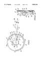
- FIG. 1is a top cross-sectional view of three levels defined by lines AA and BB of a first embodiment of a composite antenna of the present invention
- FIG. 2is a cross-sectional view of the composite antenna of FIG. 1 taken through lines AA and BB;
- FIG. 2Aillustrates an embodiment of a lower electronically conductive disc utilized in the embodiment of the composite antenna illustrated in FIGS. 1 and 2;
- FIG. 3is a perspective view of a third embodiment of an antenna of the present invention.
- FIG. 4is a side view of the antenna of FIG. 3;
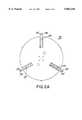
- FIGS. 5 and 5Aare plan views of the top and bottom electrically conductive discs comprising the antenna shown in FIGS. 1, 2, 3 and 4;
- FIG. 6illustrates a shunt leg of the antenna of FIG. 3
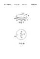
- FIG. 7is a perspective view of a fourth embodiment of an antenna of the present invention.
- FIG. 8is a bottom plan view of the antenna of FIG. 7;
- FIGS. 9A and 9Billustrate the antenna of FIG. 7 having a base mounted coaxial cable and a side fed coaxial cable, respectively.
- FIG. 10is a side view of a second embodiment of the composite antenna of the present invention comprising a dielectric filled antenna.
- FIGS. 1 and 2illustrate a composite antenna 10 in accordance with a first embodiment of the present invention.
- the composite antenna 10is comprised of a combination of a first antenna 12 and a second GPS antenna 14.
- the second antennais not limited only to a GPS antenna but may, for example, instead comprise a high frequency disk antenna having a frequency response of the order of 2.5 Ghz, a monopole whip antenna or other antennas which may be practically mounted atop the first antenna 12.
- the first antenna 12is of a generally circular shape in plan and is designed for application in a cellular communication band and comprises a pair of electrically conductive discs 16 and 18 shown in FIG. 5A and 5B, using an alternative embodiment than that employed in FIGS. 1 and 2.
- FIG. 2Aillustrates an embodiment of the lower electrically conductive disc 18 utilized in the composite antenna of FIGS. 1 and 2.
- the lower electrically conductive disc 18 as shown in FIG. 2Acomprises shunt legs 20 which are bent in substantially two places as shown in FIG. 2.
- a first length 20A of the shunt legs 20determines the spacing between the electrically conductive discs 16 and 18.
- a second length 20B of the shunt legs 20may be designed along with the lower electrically conductive disc 18 to be of different lengths and, thereby, functions to tune the characteristic impedance of the first antenna 12.
- first and second lengths 20A and 20B of the shunt legs 20may also be independently adjusted such that the distance between the electrically conductive discs 16 and 18 may be kept the same while altering the length of the second length 20 of the shunt leg 20.
- each of the shunt legs 20may be adjusted in first lengths 20A and/or second lengths 20B independently of any other shunt leg 20.
- the diameter of the first antenna 12is approximately three-tenths of one wavelength of a signal desired to be transmitted and/or received.
- the first antenna 12 of the first embodimentis configured to operate at a frequency of 824 to 896 MHz; thus, the diameter of the first antenna 12 is approximately 10.16 cm.
- Free spaceyields a permittivity constant of 10-9/36 ⁇ F/m whereas typical dielectrics yield substantially higher permittivity constants.
- One component of impedanceis equivalent to the permittivity constant of the dielectric material multiplied by the area of the discs divided by the distance between the discs. Therefore, in order to retain the same impedance and thus frequency response of the antenna as the permittivity constant is increased the distance between the plates must also be increased.
- the first antenna 12it is desired to implement the first antenna 12 with a volume of free space between the electrically conductive discs 16 and 18.
- free spacerather than a dielectric reduces the effective permittivity constant and, as demonstrated by the preceding analysis, this permits the distance between the electrically conductive discs 16 and 18 to be kept to a minimum value.
- This minimum valuehas been found to be between three to six-hundredths of the wavelength of the signal desired to be transmitted and/or received.
- the thickness of the shunt legs 20also has an effect on impedance as the distance between the discs becomes greater. In this first embodiment, the distance between the electrically conductive discs 16 and 18, is approximately 1.143 cm.
- the electrically conductive discs 16 and 18are fabricated from a sheet of metal such as brass by stamping processes well known in the art.
- the upper electrically conductive disc 16is substantially circular and has three shunt legs 20 attached integral to its perimeter but may be attached at other convenient locations as well as shown by FIG. 2A.
- Each of the shunt legs 20are bent such that the shunt legs 20 act as supporting legs capable of mating with associated holes 22 formed in the lower electrically conductive disc 18 as shown in FIGS. 5A and 5B.
- each shunt leg 20illustrates the distal ends of each shunt leg 20, which are twisted at recessed portions 24.
- Alternative methods of connecting the shunt legs 20are within the scope of the present invention and comprise soldering, spot welding and substantially any other method which provides both a mechanically stable connection as well as electrical connectivity.
- a coaxial cable 30may be integrated with the first antenna 12 by connecting an outer conductive shield of the coaxial cable 30 to the lower electrically conductive disc 18 and feeding an inner conductor 30A of the coaxial cable 30 through an opening 26 in the lower electrically conductive disc 18 insulated from the disc 18 and connecting the inner conductor 30A of the coaxial cable 30 to the center feed 28 of the upper electrically conductive disc 16.
- an excitation signalmay be applied or an input signal received via the first antenna 12 and the coaxial cable in a manner well known in the art. Specifically, as a result of this center feed to the first antenna a circular excitation pattern is produced resulting in the standard monopole antenna pattern typically found in mobile cellular communication whip antennas.
- the shunt legs 20provide mechanical stability between the electrically conductive discs 16 and 18, which is particularly important in the first embodiment due to the use of free space in the volume between the electrically conductive discs 16 and 18 as opposed to a solid mass of dielectric material. Since the permittivity of the discs is decreased as the number of shunts is increased it is preferable to use a minimal number of shunts in order to keep the size of the electrically conductive discs 16 and 18 as small as possible (i.e. since larger discs compensate for the reduction in permittivity) for a given operational frequency and corresponding impedance, however, the use of only two shunts would not provide the required structural integrity. Thus, it has been found that three shunts optimizes the structural integrity of the first antenna 12 while keeping the size of the first antenna 12 as small as possible.
- Free spaceyields a permittivity constant of 10-9/36 ⁇ F/m whereas typical dielectrics yield substantially higher permittivity constants.
- One component of impedanceis equivalent to the permittivity constant of the dielectric material multiplied by the area of the discs divided by the distance between the discs. Therefore, the width W of the shunt legs 20 also has an effect on the distance between the discs since as the shunt legs 20 become thicker the permittivity decreases thereby requiring a greater distance in order to maintain the same impedance.
- the active GPS antenna 14is fastened on top of the upper electrically conductive disc 18 via means well known in the art.
- the active GPS antenna 14is typically equivalent to the GPS antenna used in the DM N91 series GPS antenna which is commercially available through the assignee of this invention, Dorne & Margolin, Inc. 2950 Veterans Memorial Highway, Bohemia, N.Y. 11716 USA, and includes a low noise amplifier.
- a GPS feed cable 32is routed through the upper electrically conductive disc 16 and an outer conductive shield of the GPS feed cable 32 is grounded to the upper electrically conductive disc 16 via a first grounding clip 38.
- the outer conductive shield of the GPS feed cable 32is also grounded to the lower electrically conductive disc 18 via a second grounding clip 40.
- the GPS feed cable 32is electrically connected to a GPS preamp 46 which then feeds a radiating patch element 48 of the GPS antenna 14.
- the coaxial cable 30may also be routed as shown in FIGS. 1 and 2.
- the coaxial cable 30is shown grounded to the lower electrically conductive disc 18 via a third grounding clip 42 after which it traverses the lower electrically conductive disc 18 and extends across a gap between the upper electrically conductive disc 16 and the lower electrically conductive disc 18 at substantially the center of the electrically conductive discs 16 and 18.
- the coaxial cable 30is terminated at the center of the upper electrically conductive disc 16 thereby providing a center feed at this point.
- the outer conductive shield of the coaxial cable 30is additionally grounded to the lower electrically conductive disc 18 via a fourth grounding clip 44.
- a service loop 34is coiled between the upper electrically conductive disc 16 and the lower electrically conductive disc 18 in order to reduce tension by providing slack in the GPS feed cable 32 and to increase its impedance as detected within the cellular communications bandwidth, in order to nullify its effect on the performance of the first antenna 12 when connected electrically in parallel with the shunt legs 20.
- the impedance of an inductor at a given frequency of operationbeing given by the product of the vector j, the radian frequency ( ⁇ ) and the steady state inductance(L). During construction it is important that the service loop 34 be kept away from the center feed 28 of the upper electrically conductive disc 16.
- the traversal of the GPS feed cable 32 through the lower electrically conductive disc 18 to the GPS antenna 14does not create significant interference with the operation of the first antenna 12. This is due to the fact that the GPS feed cable 32 presents a high impedance inductor within the cellular communications bandwidth electrically connected in parallel with the low impedance inductor represented by the shunt legs 20.
- the GPS feed cable 32appears as a high impedance inductor at the frequencies of the cellular communications bandwidth due to the composition of the feed cable 32 and the length of the service loop 34 being significantly longer than that of the shunt legs 20.
- the impedance of an inductor at a given frequency of operationbeing given by the product of the vector j, the radian frequency (107 ) and the steady state inductance(L).
- the corresponding impedance of the shunt legs 20will also increase and their length must be kept within predetermined limits in order to continue to counteract the effect of the GPS feed cable 32. If the shunt legs 20 were not part of the present invention a different artifice would be required to nullify the effects of the GPS feed cable 32 on the cellular reception and transmission of the first antenna 12.
- a radome 36is shown in FIGS. 1 and 2 as being cut away to reveal the GPS antenna 14 and the first antenna 12.
- the radome 36is typically ultrasonically welded to a bottom cover 50 around the perimeter of the bottom cover 50 in order to create a waterproof seal. Both the radome 36 and the bottom cover 50 are typically constructed from a plastic or resin material for protection from environmental elements.
- a magnetic mount 52may also be affixed to the bottom plate 50 to facilitate mounting on any of a variety of metallic surfaces such as the rear deck of an automobile.
- a standoff 54is designed to increase the integrity of the first antenna 12 and to maintain a constant distance between the upper electrically conductive disc 16 and the lower electrically conductive disc 18 under normal operating conditions.
- the GPS feed cable 32typically comprises an sma connector 56 and the coaxial cable 30 typically comprises a bnc connector 58 for ease of installation.
- the GPS antenna 14may be mounted atop a dielectric filled antenna 60 such as that shown in FIG. 7.
- the second antennais not limited only to a GPS antenna but may, for example, instead comprise a high frequency disk antenna having a frequency response of the order of 2.5 Ghz, a monopole whip antenna or other antennas which may be practically mounted atop the first antenna 12.
- the complete structure of the composite antenna of the second embodimentis shown in FIG. 10.
- the dielectric filled antenna 60comprises a dielectric substrate 62 rather than a volume of free space between upper and lower electrically conductive layers 64 and 66 as described for the first embodiment.
- the dielectric substrate 62may be a plastic material such as the composite marketed under the tradename ULTEM.
- the dielectric filled antenna 60is of unitary construction, rather than the multi-piece assembly shown in FIG. 3 of the first embodiment.
- the dielectric substrate 62is essentially cylindrical in shape and comprises the upper electrically conductive layer 64, the lower electrically conductive layer 66, and a cylindrical side surface 68 as shown in FIG. 7.
- the upper and lower electrically conductive layers 64 and 66 respectively,are coated with an electrically conductive material such as copper by an electroplating process or other process well known in the art.
- three shunts 70are located on the cylindrical side surface 68 along approximately the perimeter of the dielectric substrate 62 (or other convenient locations) approximately 120 degrees from each other and are formed by an electroplating process well known in the art.
- the shunts 70provide electrical connectivity between the upper electrically conductive layer 64 and the lower electrically conductive layer 66. As shown in FIG.
- the width W of each shunt 70is designed large enough to permit a coaxial cable of typical dimensions to be disposed alongside the shunt 70 without disturbing the fields generated by the dielectric filled antenna 60.
- the width W of shunts 70may be varied according to the distance between the upper electrically conductive layer 64 and the lower electrically conductive layer 66 in order to impedance match the antenna since the width W is related to the permittivity which is directly related to the impedance of the first antenna 12.
- FIG. 8shows a bottom plan view of the lower electrically conductive layer 66 of the dielectric filled antenna 70.
- a coaxial cablemay be secured to the lower electrically conductive layer 66 by a method well known in the art.
- Four mounting holes 72are shown for a coaxial connector having four connection points to be mated with the four mounting holes 72.
- the outer conductive shield of the coaxial cable 30is electrically connected to the connector, and also to the lower electrically conductive layer 66.
- the inner conductor 30A of the coaxial cable 30is fed through a bore 74 which is insulated from the lower electrically conductive layer 66, through the dielectric substrate 62, and is soldered or otherwise electrically connected to the upper electrically conductive layer 64.
- the coaxial cable 30may be fed directly to the dielectric filled antenna 70 from the side by using a recessed slot 76.
- the recessed slot 76serves to position and countersink the coaxial cable 30 permitting a flush mounting of the lower electrically conductive layer 66.
- the outer conductive shield and inner conductor 30A of the coaxial cable 30are then connected to the lower and upper electrically conductive layers 66 and 64, respectively, as described above.
- the dielectric filled antenna 70may be adapted for direct center feed or side feed applications according to the application, as shown in FIGS. 9A and 9B respectively.
- the mounting technique for the GPS antenna 14 atop the dielectric filled antenna 60 in the second embodimentcan be substantially the same as that described above in the first embodiment except that the GPS feed cable 32 would typically be routed around the outside of the dielectric filled antenna 60 rather than between the upper electrically conductive disc 16 and the lower electrically conductive disc 18 since there is no longer free space but rather the solid dielectric therebetween
- FIGS. 3 and 4illustrate the first antenna 12 in accordance with a third embodiment of the present invention.
- the third embodimentinvolves the use of the first antenna 12 designed for application in the cellular band of a generally circular shape which comprises a pair of electrically conductive discs 16 and 18 having a volume of free space between the discs as shown in FIG. 5A and 5B without the addition of the second or GPS antenna 14.
- FIGS. 7 and 8illustrate a fourth embodiment of the present invention.
- the fourth embodimentinvolves the use of the dielectric filled antenna 60 without the addition of the second or GPS antenna 14.
Landscapes
- Physics & Mathematics (AREA)
- Electromagnetism (AREA)
- Waveguide Aerials (AREA)
- Variable-Direction Aerials And Aerial Arrays (AREA)
Abstract
Description
Claims (44)
Priority Applications (1)
| Application Number | Priority Date | Filing Date | Title |
|---|---|---|---|
| US08/847,575US5864318A (en) | 1996-04-26 | 1997-04-24 | Composite antenna for cellular and gps communications |
Applications Claiming Priority (2)
| Application Number | Priority Date | Filing Date | Title |
|---|---|---|---|
| US1632796P | 1996-04-26 | 1996-04-26 | |
| US08/847,575US5864318A (en) | 1996-04-26 | 1997-04-24 | Composite antenna for cellular and gps communications |
Publications (1)
| Publication Number | Publication Date |
|---|---|
| US5864318Atrue US5864318A (en) | 1999-01-26 |
Family
ID=21776576
Family Applications (1)
| Application Number | Title | Priority Date | Filing Date |
|---|---|---|---|
| US08/847,575Expired - Fee RelatedUS5864318A (en) | 1996-04-26 | 1997-04-24 | Composite antenna for cellular and gps communications |
Country Status (4)
| Country | Link |
|---|---|
| US (1) | US5864318A (en) |
| AU (1) | AU3116197A (en) |
| CA (1) | CA2253265C (en) |
| WO (1) | WO1997041619A1 (en) |
Cited By (60)
| Publication number | Priority date | Publication date | Assignee | Title |
|---|---|---|---|---|
| US6098547A (en)* | 1998-06-01 | 2000-08-08 | Rockwell Collins, Inc. | Artillery fuse circumferential slot antenna for positioning and telemetry |
| US6111549A (en)* | 1997-03-27 | 2000-08-29 | Satloc, Inc. | Flexible circuit antenna and method of manufacture thereof |
| US6320548B1 (en)* | 2000-01-26 | 2001-11-20 | Integral Technologies, Inc. | Dual disk active antenna |
| EP1178566A1 (en)* | 2000-08-03 | 2002-02-06 | Diehl Munitionssysteme GmbH & Co. KG | Slot antenna for artillery ammunition |
| US20030210193A1 (en)* | 2002-05-13 | 2003-11-13 | Rossman Court Emerson | Low Profile Two-Antenna Assembly Having a Ring Antenna and a Concentrically-Located Monopole Antenna |
| US6693535B2 (en)* | 2001-11-29 | 2004-02-17 | Motorola, Inc. | System and method for controlling the interior temperature of a vehicle |
| US6718619B2 (en)* | 2000-12-15 | 2004-04-13 | Atheros Communications, Inc. | Method of manufacturing a central stem monopole antenna |
| US20040196200A1 (en)* | 2003-04-04 | 2004-10-07 | Sievenpiper Daniel F. | Low-profile antenna |
| US20040239568A1 (en)* | 2003-04-11 | 2004-12-02 | Takeshi Masutani | Multiple antenna |
| US20050116863A1 (en)* | 2003-11-27 | 2005-06-02 | Alps Electric Co., Ltd. | Circularly polarized wave antenna device suitable for miniaturization |
| US20050237184A1 (en)* | 2000-01-24 | 2005-10-27 | Scott Muirhead | RF-enabled pallet |
| US20050241548A1 (en)* | 2000-01-24 | 2005-11-03 | Muirhead Scott A W | Thermoformed platform having a communications device |
| US20060028379A1 (en)* | 2000-03-13 | 2006-02-09 | Rcd Technology Corp. | Method for forming radio frequency antenna |
| WO2006086658A1 (en) | 2005-02-11 | 2006-08-17 | Cornwell, James | Antenna system |
| US20060244667A1 (en)* | 2005-04-28 | 2006-11-02 | Thompson Loren M | Satellite antenna |
| US20070198185A1 (en)* | 2002-12-11 | 2007-08-23 | Mcclure John A | GNSS control system and method |
| US20080122610A1 (en)* | 2000-01-24 | 2008-05-29 | Nextreme L.L.C. | RF-enabled pallet |
| US20080167770A1 (en)* | 2007-01-05 | 2008-07-10 | Beeline Technologies Pty Ltd | Vehicle control system |
| US20080205494A1 (en)* | 2007-02-27 | 2008-08-28 | Whitehead Michael L | Unbiased code phase discriminator |
| US20090085815A1 (en)* | 2007-09-27 | 2009-04-02 | Jakab Andrew J | Tightly-coupled pcb gnss circuit and manufacturing method |
| US20090099730A1 (en)* | 2003-03-20 | 2009-04-16 | Mcclure John A | Satellite based vehicle guidance control in straight and contour modes |
| US20090121932A1 (en)* | 2003-03-20 | 2009-05-14 | Whitehead Michael L | Multi-antenna gnss positioning method and system |
| US20090164067A1 (en)* | 2003-03-20 | 2009-06-25 | Whitehead Michael L | Multiple-antenna gnss control system and method |
| US20090204281A1 (en)* | 2008-02-10 | 2009-08-13 | Hemisphere Gps Llc | Visual, gnss and gyro autosteering control |
| US20090251366A1 (en)* | 2008-04-08 | 2009-10-08 | Mcclure John A | Gnss-based mobile communication system and method |
| US20090305652A1 (en)* | 2006-10-09 | 2009-12-10 | Pirelli & C. S.P.A. | Dielectric antenna device for wireless communications |
| US20100109944A1 (en)* | 2003-03-20 | 2010-05-06 | Whitehead Michael L | Gnss-based tracking of fixed or slow-moving structures |
| US20100161179A1 (en)* | 2008-12-22 | 2010-06-24 | Mcclure John A | Integrated dead reckoning and gnss/ins positioning |
| US20100176991A1 (en)* | 2008-12-11 | 2010-07-15 | Webber Mark R | Gnss superband asic with simultaneous multi-frequency down conversion |
| US20100185366A1 (en)* | 2005-07-19 | 2010-07-22 | Heiniger Richard W | Adaptive machine control system and method |
| US20100312428A1 (en)* | 2003-03-20 | 2010-12-09 | Roberge Andre C | Gnss guidance and machine control |
| US20110015817A1 (en)* | 2009-07-17 | 2011-01-20 | Reeve David R | Optical tracking vehicle control system and method |
| US20110022238A1 (en)* | 2009-07-22 | 2011-01-27 | Pollock Colin J | Gnss control system and method for irrigation and related applications |
| US20110018765A1 (en)* | 2007-10-08 | 2011-01-27 | Whitehead Michael L | Gnss receiver and external storage device system and gnss data processing method |
| US20110025555A1 (en)* | 2009-07-29 | 2011-02-03 | Whitehead Michael L | System and method for augmenting dgnss with internally-generated differential correction |
| US20110054729A1 (en)* | 2004-03-19 | 2011-03-03 | Whitehead Michael L | Multi-antenna gnss control system and method |
| US20110057834A1 (en)* | 2009-09-04 | 2011-03-10 | Miller Steven R | Multi-frequency gnss receiver baseband dsp |
| US20110140990A1 (en)* | 2009-06-15 | 2011-06-16 | Le Sage Hendrikus A | Antenna identification module |
| US20110172887A1 (en)* | 2009-11-30 | 2011-07-14 | Reeve David R | Vehicle assembly control method for collaborative behavior |
| US20110196565A1 (en)* | 2010-02-09 | 2011-08-11 | Collins Dennis M | Gnss contour guidance path selection |
| US8085196B2 (en) | 2009-03-11 | 2011-12-27 | Hemisphere Gps Llc | Removing biases in dual frequency GNSS receivers using SBAS |
| US8265826B2 (en) | 2003-03-20 | 2012-09-11 | Hemisphere GPS, LLC | Combined GNSS gyroscope control system and method |
| US8271194B2 (en) | 2004-03-19 | 2012-09-18 | Hemisphere Gps Llc | Method and system using GNSS phase measurements for relative positioning |
| US8386129B2 (en) | 2009-01-17 | 2013-02-26 | Hemipshere GPS, LLC | Raster-based contour swathing for guidance and variable-rate chemical application |
| US8548649B2 (en) | 2009-10-19 | 2013-10-01 | Agjunction Llc | GNSS optimized aircraft control system and method |
| US8649930B2 (en) | 2009-09-17 | 2014-02-11 | Agjunction Llc | GNSS integrated multi-sensor control system and method |
| US20150042536A1 (en)* | 2013-08-09 | 2015-02-12 | Pulse Electronics, Inc. | Low passive intermodulation antenna apparatus and methods of use |
| US20150123868A1 (en)* | 2013-11-06 | 2015-05-07 | Motorola Solutions, Inc. | Compact, multi-port, mimo antenna with high port isolation and low pattern correlation and method of making same |
| US9046601B2 (en) | 2009-06-15 | 2015-06-02 | Hendrikus A. Le Sage | Handheld antenna attitude measuring system |
| US20150263434A1 (en) | 2013-03-15 | 2015-09-17 | SeeScan, Inc. | Dual antenna systems with variable polarization |
| WO2016114990A1 (en)* | 2015-01-14 | 2016-07-21 | Commscope Technologies Llc | Radio antenna element arm retaining clip |
| WO2016180183A1 (en)* | 2015-08-04 | 2016-11-17 | 中兴通讯股份有限公司 | Broadband antenna |
| US9722308B2 (en) | 2014-08-28 | 2017-08-01 | Pulse Finland Oy | Low passive intermodulation distributed antenna system for multiple-input multiple-output systems and methods of use |
| US9880562B2 (en) | 2003-03-20 | 2018-01-30 | Agjunction Llc | GNSS and optical guidance and machine control |
| US20180175493A1 (en)* | 2016-12-15 | 2018-06-21 | Nanning Fugui Precision Industrial Co., Ltd. | Antenna device and electronic device using the same |
| USRE47101E1 (en) | 2003-03-20 | 2018-10-30 | Agjunction Llc | Control for dispensing material from vehicle |
| US10158178B2 (en) | 2013-11-06 | 2018-12-18 | Symbol Technologies, Llc | Low profile, antenna array for an RFID reader and method of making same |
| RU188184U1 (en)* | 2018-07-17 | 2019-04-02 | Руслан Варисович Шаймарданов | Wide Range Antenna for Satellite Navigation System (GNSS) |
| US10608348B2 (en) | 2012-03-31 | 2020-03-31 | SeeScan, Inc. | Dual antenna systems with variable polarization |
| USRE48527E1 (en) | 2007-01-05 | 2021-04-20 | Agjunction Llc | Optical tracking vehicle control system and method |
Families Citing this family (5)
| Publication number | Priority date | Publication date | Assignee | Title |
|---|---|---|---|---|
| DE10031255A1 (en) | 2000-06-27 | 2002-01-17 | Bosch Gmbh Robert | slot antenna |
| SE518331C2 (en) | 2000-10-27 | 2002-09-24 | Ericsson Telefon Ab L M | Mobile telephone antenna device for a first and a second radio application |
| US20040021606A1 (en)* | 2002-07-11 | 2004-02-05 | Alps Electric Co., Ltd. | Small plane antenna and composite antenna using the same |
| JP2005159836A (en)* | 2003-11-27 | 2005-06-16 | Alps Electric Co Ltd | Antenna device |
| US7239270B2 (en) | 2005-05-31 | 2007-07-03 | Research In Motion Limited | Mobile wireless communications device comprising a satellite positioning system antenna and electrically conductive director element therefor |
Citations (14)
| Publication number | Priority date | Publication date | Assignee | Title |
|---|---|---|---|---|
| US2996713A (en)* | 1956-11-05 | 1961-08-15 | Antenna Engineering Lab | Radial waveguide antenna |
| US4366484A (en)* | 1978-12-29 | 1982-12-28 | Ball Corporation | Temperature compensated radio frequency antenna and methods related thereto |
| US4369447A (en)* | 1979-07-12 | 1983-01-18 | Emi Limited | Annular slot antenna |
| US4410891A (en)* | 1979-12-14 | 1983-10-18 | The United States Of America As Represented By The Secretary Of The Army | Microstrip antenna with polarization diversity |
| US4682180A (en)* | 1985-09-23 | 1987-07-21 | American Telephone And Telegraph Company At&T Bell Laboratories | Multidirectional feed and flush-mounted surface wave antenna |
| US4994820A (en)* | 1988-12-16 | 1991-02-19 | Nissan Motor Co., Ltd. | Plane antenna |
| US5041838A (en)* | 1990-03-06 | 1991-08-20 | Liimatainen William J | Cellular telephone antenna |
| US5061939A (en)* | 1989-05-23 | 1991-10-29 | Harada Kogyo Kabushiki Kaisha | Flat-plate antenna for use in mobile communications |
| US5073761A (en)* | 1990-06-05 | 1991-12-17 | Westinghouse Electric Corp. | Non-contacting radio frequency coupler connector |
| US5099249A (en)* | 1987-10-13 | 1992-03-24 | Seavey Engineering Associates, Inc. | Microstrip antenna for vehicular satellite communications |
| US5121127A (en)* | 1988-09-30 | 1992-06-09 | Sony Corporation | Microstrip antenna |
| US5220334A (en)* | 1988-02-12 | 1993-06-15 | Alcatel Espace | Multifrequency antenna, useable in particular for space telecommunications |
| US5291210A (en)* | 1988-12-27 | 1994-03-01 | Harada Kogyo Kabushiki Kaisha | Flat-plate antenna with strip line resonator having capacitance for impedance matching the feeder |
| US5519406A (en)* | 1994-03-09 | 1996-05-21 | Matsushita Electric Works, Ltd. | Low profile polarization diversity planar antenna |
- 1997
- 1997-04-24USUS08/847,575patent/US5864318A/ennot_activeExpired - Fee Related
- 1997-04-25CACA002253265Apatent/CA2253265C/ennot_activeExpired - Fee Related
- 1997-04-25WOPCT/US1997/007076patent/WO1997041619A1/enactiveApplication Filing
- 1997-04-25AUAU31161/97Apatent/AU3116197A/ennot_activeAbandoned
Patent Citations (14)
| Publication number | Priority date | Publication date | Assignee | Title |
|---|---|---|---|---|
| US2996713A (en)* | 1956-11-05 | 1961-08-15 | Antenna Engineering Lab | Radial waveguide antenna |
| US4366484A (en)* | 1978-12-29 | 1982-12-28 | Ball Corporation | Temperature compensated radio frequency antenna and methods related thereto |
| US4369447A (en)* | 1979-07-12 | 1983-01-18 | Emi Limited | Annular slot antenna |
| US4410891A (en)* | 1979-12-14 | 1983-10-18 | The United States Of America As Represented By The Secretary Of The Army | Microstrip antenna with polarization diversity |
| US4682180A (en)* | 1985-09-23 | 1987-07-21 | American Telephone And Telegraph Company At&T Bell Laboratories | Multidirectional feed and flush-mounted surface wave antenna |
| US5099249A (en)* | 1987-10-13 | 1992-03-24 | Seavey Engineering Associates, Inc. | Microstrip antenna for vehicular satellite communications |
| US5220334A (en)* | 1988-02-12 | 1993-06-15 | Alcatel Espace | Multifrequency antenna, useable in particular for space telecommunications |
| US5121127A (en)* | 1988-09-30 | 1992-06-09 | Sony Corporation | Microstrip antenna |
| US4994820A (en)* | 1988-12-16 | 1991-02-19 | Nissan Motor Co., Ltd. | Plane antenna |
| US5291210A (en)* | 1988-12-27 | 1994-03-01 | Harada Kogyo Kabushiki Kaisha | Flat-plate antenna with strip line resonator having capacitance for impedance matching the feeder |
| US5061939A (en)* | 1989-05-23 | 1991-10-29 | Harada Kogyo Kabushiki Kaisha | Flat-plate antenna for use in mobile communications |
| US5041838A (en)* | 1990-03-06 | 1991-08-20 | Liimatainen William J | Cellular telephone antenna |
| US5073761A (en)* | 1990-06-05 | 1991-12-17 | Westinghouse Electric Corp. | Non-contacting radio frequency coupler connector |
| US5519406A (en)* | 1994-03-09 | 1996-05-21 | Matsushita Electric Works, Ltd. | Low profile polarization diversity planar antenna |
Non-Patent Citations (2)
| Title |
|---|
| Schaubert, Jones and Reggia, Conformal Dielectric Filled Edge Slot Antennas with Inductive Post Tuning, IEEE Transactions on Antennas and Propagation, vol. AP 27, No. 5, Sep. 1979.* |
| Schaubert, Jones and Reggia, Conformal Dielectric-Filled Edge-Slot Antennas with Inductive-Post Tuning, IEEE Transactions on Antennas and Propagation, vol. AP-27, No. 5, Sep. 1979. |
Cited By (112)
| Publication number | Priority date | Publication date | Assignee | Title |
|---|---|---|---|---|
| US6111549A (en)* | 1997-03-27 | 2000-08-29 | Satloc, Inc. | Flexible circuit antenna and method of manufacture thereof |
| US6098547A (en)* | 1998-06-01 | 2000-08-08 | Rockwell Collins, Inc. | Artillery fuse circumferential slot antenna for positioning and telemetry |
| US7789024B2 (en) | 2000-01-24 | 2010-09-07 | Nextreme, Llc | Thermoformed platform having a communications device |
| US20070171080A1 (en)* | 2000-01-24 | 2007-07-26 | Scott Muirhead | Material handling apparatus with a cellular communications device |
| US7342496B2 (en) | 2000-01-24 | 2008-03-11 | Nextreme Llc | RF-enabled pallet |
| US20080121339A1 (en)* | 2000-01-24 | 2008-05-29 | Nextreme L.L.C. | Thermoformed platform having a communications device |
| US7948371B2 (en) | 2000-01-24 | 2011-05-24 | Nextreme Llc | Material handling apparatus with a cellular communications device |
| US9230227B2 (en) | 2000-01-24 | 2016-01-05 | Nextreme, Llc | Pallet |
| US20070163472A1 (en)* | 2000-01-24 | 2007-07-19 | Scott Muirhead | Material handling apparatus having a reader/writer |
| US20060243174A1 (en)* | 2000-01-24 | 2006-11-02 | Nextreme, L.L.C. | Thermoformed platform having a communications device |
| US8585850B2 (en) | 2000-01-24 | 2013-11-19 | Nextreme, Llc | Thermoformed platform having a communications device |
| US20050237184A1 (en)* | 2000-01-24 | 2005-10-27 | Scott Muirhead | RF-enabled pallet |
| US20050241548A1 (en)* | 2000-01-24 | 2005-11-03 | Muirhead Scott A W | Thermoformed platform having a communications device |
| US8077040B2 (en) | 2000-01-24 | 2011-12-13 | Nextreme, Llc | RF-enabled pallet |
| US20080122610A1 (en)* | 2000-01-24 | 2008-05-29 | Nextreme L.L.C. | RF-enabled pallet |
| US7752980B2 (en) | 2000-01-24 | 2010-07-13 | Nextreme Llc | Material handling apparatus having a reader/writer |
| US7804400B2 (en) | 2000-01-24 | 2010-09-28 | Nextreme, Llc | Thermoformed platform having a communications device |
| US6320548B1 (en)* | 2000-01-26 | 2001-11-20 | Integral Technologies, Inc. | Dual disk active antenna |
| US20060028379A1 (en)* | 2000-03-13 | 2006-02-09 | Rcd Technology Corp. | Method for forming radio frequency antenna |
| US7298331B2 (en)* | 2000-03-13 | 2007-11-20 | Rcd Technology, Inc. | Method for forming radio frequency antenna |
| EP1178566A1 (en)* | 2000-08-03 | 2002-02-06 | Diehl Munitionssysteme GmbH & Co. KG | Slot antenna for artillery ammunition |
| US6718619B2 (en)* | 2000-12-15 | 2004-04-13 | Atheros Communications, Inc. | Method of manufacturing a central stem monopole antenna |
| US6693535B2 (en)* | 2001-11-29 | 2004-02-17 | Motorola, Inc. | System and method for controlling the interior temperature of a vehicle |
| US6812902B2 (en)* | 2002-05-13 | 2004-11-02 | Centurion Wireless Technologies, Inc. | Low profile two-antenna assembly having a ring antenna and a concentrically-located monopole antenna |
| US20030210193A1 (en)* | 2002-05-13 | 2003-11-13 | Rossman Court Emerson | Low Profile Two-Antenna Assembly Having a Ring Antenna and a Concentrically-Located Monopole Antenna |
| US7885745B2 (en) | 2002-12-11 | 2011-02-08 | Hemisphere Gps Llc | GNSS control system and method |
| US20070198185A1 (en)* | 2002-12-11 | 2007-08-23 | Mcclure John A | GNSS control system and method |
| US8686900B2 (en) | 2003-03-20 | 2014-04-01 | Hemisphere GNSS, Inc. | Multi-antenna GNSS positioning method and system |
| US8140223B2 (en) | 2003-03-20 | 2012-03-20 | Hemisphere Gps Llc | Multiple-antenna GNSS control system and method |
| US8594879B2 (en) | 2003-03-20 | 2013-11-26 | Agjunction Llc | GNSS guidance and machine control |
| US10168714B2 (en) | 2003-03-20 | 2019-01-01 | Agjunction Llc | GNSS and optical guidance and machine control |
| USRE47101E1 (en) | 2003-03-20 | 2018-10-30 | Agjunction Llc | Control for dispensing material from vehicle |
| US20090099730A1 (en)* | 2003-03-20 | 2009-04-16 | Mcclure John A | Satellite based vehicle guidance control in straight and contour modes |
| US20090121932A1 (en)* | 2003-03-20 | 2009-05-14 | Whitehead Michael L | Multi-antenna gnss positioning method and system |
| US20090164067A1 (en)* | 2003-03-20 | 2009-06-25 | Whitehead Michael L | Multiple-antenna gnss control system and method |
| US8138970B2 (en) | 2003-03-20 | 2012-03-20 | Hemisphere Gps Llc | GNSS-based tracking of fixed or slow-moving structures |
| US9880562B2 (en) | 2003-03-20 | 2018-01-30 | Agjunction Llc | GNSS and optical guidance and machine control |
| US9886038B2 (en) | 2003-03-20 | 2018-02-06 | Agjunction Llc | GNSS and optical guidance and machine control |
| US20100109944A1 (en)* | 2003-03-20 | 2010-05-06 | Whitehead Michael L | Gnss-based tracking of fixed or slow-moving structures |
| US20100312428A1 (en)* | 2003-03-20 | 2010-12-09 | Roberge Andre C | Gnss guidance and machine control |
| US8190337B2 (en) | 2003-03-20 | 2012-05-29 | Hemisphere GPS, LLC | Satellite based vehicle guidance control in straight and contour modes |
| US8265826B2 (en) | 2003-03-20 | 2012-09-11 | Hemisphere GPS, LLC | Combined GNSS gyroscope control system and method |
| US7050003B2 (en)* | 2003-04-04 | 2006-05-23 | General Motors Corporation | Low-profile antenna |
| US20040196200A1 (en)* | 2003-04-04 | 2004-10-07 | Sievenpiper Daniel F. | Low-profile antenna |
| US20040239568A1 (en)* | 2003-04-11 | 2004-12-02 | Takeshi Masutani | Multiple antenna |
| US7071878B2 (en)* | 2003-04-11 | 2006-07-04 | Matsushita Electric Industrial Co., Ltd. | Multiple antenna |
| US6975272B2 (en)* | 2003-11-27 | 2005-12-13 | Alps Electric Co., Ltd. | Circularly polarized wave antenna device suitable for miniaturization |
| US20050116863A1 (en)* | 2003-11-27 | 2005-06-02 | Alps Electric Co., Ltd. | Circularly polarized wave antenna device suitable for miniaturization |
| US8583315B2 (en) | 2004-03-19 | 2013-11-12 | Agjunction Llc | Multi-antenna GNSS control system and method |
| US8271194B2 (en) | 2004-03-19 | 2012-09-18 | Hemisphere Gps Llc | Method and system using GNSS phase measurements for relative positioning |
| US20110054729A1 (en)* | 2004-03-19 | 2011-03-03 | Whitehead Michael L | Multi-antenna gnss control system and method |
| WO2006086658A1 (en) | 2005-02-11 | 2006-08-17 | Cornwell, James | Antenna system |
| US20080024374A1 (en)* | 2005-02-11 | 2008-01-31 | James Cornwell | Antenna system |
| US7733280B2 (en) | 2005-02-11 | 2010-06-08 | Kaonetics Technologies, Inc. | Antenna system |
| US7283100B2 (en)* | 2005-04-28 | 2007-10-16 | Delphi Technologies, Inc. | Satellite antenna |
| US20060244667A1 (en)* | 2005-04-28 | 2006-11-02 | Thompson Loren M | Satellite antenna |
| US8214111B2 (en) | 2005-07-19 | 2012-07-03 | Hemisphere Gps Llc | Adaptive machine control system and method |
| US20100185366A1 (en)* | 2005-07-19 | 2010-07-22 | Heiniger Richard W | Adaptive machine control system and method |
| US10727597B2 (en)* | 2006-10-09 | 2020-07-28 | Advanced Digital Broadcast S.A. | Dielectric antenna device for wireless communications |
| US20090305652A1 (en)* | 2006-10-09 | 2009-12-10 | Pirelli & C. S.P.A. | Dielectric antenna device for wireless communications |
| USRE48527E1 (en) | 2007-01-05 | 2021-04-20 | Agjunction Llc | Optical tracking vehicle control system and method |
| US20110118938A1 (en)* | 2007-01-05 | 2011-05-19 | Andrew John Macdonald | Vehicle control system |
| US7835832B2 (en) | 2007-01-05 | 2010-11-16 | Hemisphere Gps Llc | Vehicle control system |
| US20080167770A1 (en)* | 2007-01-05 | 2008-07-10 | Beeline Technologies Pty Ltd | Vehicle control system |
| US8000381B2 (en) | 2007-02-27 | 2011-08-16 | Hemisphere Gps Llc | Unbiased code phase discriminator |
| US20080205494A1 (en)* | 2007-02-27 | 2008-08-28 | Whitehead Michael L | Unbiased code phase discriminator |
| US7948769B2 (en) | 2007-09-27 | 2011-05-24 | Hemisphere Gps Llc | Tightly-coupled PCB GNSS circuit and manufacturing method |
| US20090085815A1 (en)* | 2007-09-27 | 2009-04-02 | Jakab Andrew J | Tightly-coupled pcb gnss circuit and manufacturing method |
| US8456356B2 (en) | 2007-10-08 | 2013-06-04 | Hemisphere Gnss Inc. | GNSS receiver and external storage device system and GNSS data processing method |
| US20110018765A1 (en)* | 2007-10-08 | 2011-01-27 | Whitehead Michael L | Gnss receiver and external storage device system and gnss data processing method |
| US20090204281A1 (en)* | 2008-02-10 | 2009-08-13 | Hemisphere Gps Llc | Visual, gnss and gyro autosteering control |
| US9002566B2 (en) | 2008-02-10 | 2015-04-07 | AgJunction, LLC | Visual, GNSS and gyro autosteering control |
| US8018376B2 (en) | 2008-04-08 | 2011-09-13 | Hemisphere Gps Llc | GNSS-based mobile communication system and method |
| US20090251366A1 (en)* | 2008-04-08 | 2009-10-08 | Mcclure John A | Gnss-based mobile communication system and method |
| US20100176991A1 (en)* | 2008-12-11 | 2010-07-15 | Webber Mark R | Gnss superband asic with simultaneous multi-frequency down conversion |
| US8217833B2 (en) | 2008-12-11 | 2012-07-10 | Hemisphere Gps Llc | GNSS superband ASIC with simultaneous multi-frequency down conversion |
| US20100161179A1 (en)* | 2008-12-22 | 2010-06-24 | Mcclure John A | Integrated dead reckoning and gnss/ins positioning |
| USRE48509E1 (en) | 2009-01-17 | 2021-04-13 | Agjunction Llc | Raster-based contour swathing for guidance and variable-rate chemical application |
| US8386129B2 (en) | 2009-01-17 | 2013-02-26 | Hemipshere GPS, LLC | Raster-based contour swathing for guidance and variable-rate chemical application |
| USRE47055E1 (en) | 2009-01-17 | 2018-09-25 | Agjunction Llc | Raster-based contour swathing for guidance and variable-rate chemical application |
| US8085196B2 (en) | 2009-03-11 | 2011-12-27 | Hemisphere Gps Llc | Removing biases in dual frequency GNSS receivers using SBAS |
| US8514145B2 (en) | 2009-06-15 | 2013-08-20 | Hendrikus A. Le Sage | Antenna identification module |
| US9046601B2 (en) | 2009-06-15 | 2015-06-02 | Hendrikus A. Le Sage | Handheld antenna attitude measuring system |
| US20110140990A1 (en)* | 2009-06-15 | 2011-06-16 | Le Sage Hendrikus A | Antenna identification module |
| US20110015817A1 (en)* | 2009-07-17 | 2011-01-20 | Reeve David R | Optical tracking vehicle control system and method |
| US8311696B2 (en) | 2009-07-17 | 2012-11-13 | Hemisphere Gps Llc | Optical tracking vehicle control system and method |
| US8401704B2 (en) | 2009-07-22 | 2013-03-19 | Hemisphere GPS, LLC | GNSS control system and method for irrigation and related applications |
| US20110022238A1 (en)* | 2009-07-22 | 2011-01-27 | Pollock Colin J | Gnss control system and method for irrigation and related applications |
| US20110025555A1 (en)* | 2009-07-29 | 2011-02-03 | Whitehead Michael L | System and method for augmenting dgnss with internally-generated differential correction |
| US8174437B2 (en) | 2009-07-29 | 2012-05-08 | Hemisphere Gps Llc | System and method for augmenting DGNSS with internally-generated differential correction |
| US8334804B2 (en) | 2009-09-04 | 2012-12-18 | Hemisphere Gps Llc | Multi-frequency GNSS receiver baseband DSP |
| US20110057834A1 (en)* | 2009-09-04 | 2011-03-10 | Miller Steven R | Multi-frequency gnss receiver baseband dsp |
| USRE47648E1 (en) | 2009-09-17 | 2019-10-15 | Agjunction Llc | Integrated multi-sensor control system and method |
| US8649930B2 (en) | 2009-09-17 | 2014-02-11 | Agjunction Llc | GNSS integrated multi-sensor control system and method |
| US8548649B2 (en) | 2009-10-19 | 2013-10-01 | Agjunction Llc | GNSS optimized aircraft control system and method |
| US20110172887A1 (en)* | 2009-11-30 | 2011-07-14 | Reeve David R | Vehicle assembly control method for collaborative behavior |
| US20110196565A1 (en)* | 2010-02-09 | 2011-08-11 | Collins Dennis M | Gnss contour guidance path selection |
| US8583326B2 (en) | 2010-02-09 | 2013-11-12 | Agjunction Llc | GNSS contour guidance path selection |
| US10608348B2 (en) | 2012-03-31 | 2020-03-31 | SeeScan, Inc. | Dual antenna systems with variable polarization |
| US10490908B2 (en) | 2013-03-15 | 2019-11-26 | SeeScan, Inc. | Dual antenna systems with variable polarization |
| US20150263434A1 (en) | 2013-03-15 | 2015-09-17 | SeeScan, Inc. | Dual antenna systems with variable polarization |
| US9728846B2 (en)* | 2013-08-09 | 2017-08-08 | Pulse Electronics, Inc. | Low passive intermodulation antenna apparatus and methods of use |
| US20150042536A1 (en)* | 2013-08-09 | 2015-02-12 | Pulse Electronics, Inc. | Low passive intermodulation antenna apparatus and methods of use |
| US20150123868A1 (en)* | 2013-11-06 | 2015-05-07 | Motorola Solutions, Inc. | Compact, multi-port, mimo antenna with high port isolation and low pattern correlation and method of making same |
| US10158178B2 (en) | 2013-11-06 | 2018-12-18 | Symbol Technologies, Llc | Low profile, antenna array for an RFID reader and method of making same |
| US9847571B2 (en)* | 2013-11-06 | 2017-12-19 | Symbol Technologies, Llc | Compact, multi-port, MIMO antenna with high port isolation and low pattern correlation and method of making same |
| US9722308B2 (en) | 2014-08-28 | 2017-08-01 | Pulse Finland Oy | Low passive intermodulation distributed antenna system for multiple-input multiple-output systems and methods of use |
| US10916828B2 (en) | 2015-01-14 | 2021-02-09 | Commscope Technologies Llc | Radio antenna element arm retaining clip |
| WO2016114990A1 (en)* | 2015-01-14 | 2016-07-21 | Commscope Technologies Llc | Radio antenna element arm retaining clip |
| WO2016180183A1 (en)* | 2015-08-04 | 2016-11-17 | 中兴通讯股份有限公司 | Broadband antenna |
| US20180175493A1 (en)* | 2016-12-15 | 2018-06-21 | Nanning Fugui Precision Industrial Co., Ltd. | Antenna device and electronic device using the same |
| RU188184U1 (en)* | 2018-07-17 | 2019-04-02 | Руслан Варисович Шаймарданов | Wide Range Antenna for Satellite Navigation System (GNSS) |
Also Published As
| Publication number | Publication date |
|---|---|
| AU3116197A (en) | 1997-11-19 |
| CA2253265C (en) | 2004-01-13 |
| WO1997041619A1 (en) | 1997-11-06 |
| CA2253265A1 (en) | 1997-11-06 |
Similar Documents
| Publication | Publication Date | Title |
|---|---|---|
| US5864318A (en) | Composite antenna for cellular and gps communications | |
| US5041838A (en) | Cellular telephone antenna | |
| US6646618B2 (en) | Low-profile slot antenna for vehicular communications and methods of making and designing same | |
| US6853341B1 (en) | Antenna means | |
| US5300936A (en) | Multiple band antenna | |
| US6023245A (en) | Multi-band, multiple purpose antenna particularly useful for operation in cellular and global positioning system modes | |
| US5402134A (en) | Flat plate antenna module | |
| US6906669B2 (en) | Multifunction antenna | |
| US5508710A (en) | Conformal multifunction shared-aperture antenna | |
| US5099249A (en) | Microstrip antenna for vehicular satellite communications | |
| CN204243211U (en) | There is the antenna system of low passive intermodulation | |
| US20020000944A1 (en) | Low cost compact omini-directional printed antenna | |
| EP0892461A1 (en) | An antenna assembly | |
| US10854964B2 (en) | Antenna apparatus and vehicle including the same | |
| JP2001127523A (en) | Microstrip array antenna with radome | |
| KR20010075014A (en) | Circularly polarized dielectric resonator antenna | |
| JPH05226925A (en) | Microstrip-antenna for mobile communication and manufacture thereof | |
| JP2001313518A (en) | Microstrip antenna | |
| KR20020005642A (en) | Compact dual mode integrated antenna system for terrestrial cellular and satellite telecommunications | |
| US5945950A (en) | Stacked microstrip antenna for wireless communication | |
| EP1186073A1 (en) | Patch antenna and a communication device including such an antenna | |
| US7439910B2 (en) | Three-dimensional antenna structure | |
| DE102021129915A1 (en) | LOW-PROFILE UNIVERSAL VEHICLE ANTENNA SYSTEM | |
| JP2846609B2 (en) | Dual-polarized antenna | |
| US20240322448A1 (en) | Thin sheet-like antenna for narrowband vehicular communication |
Legal Events
| Date | Code | Title | Description |
|---|---|---|---|
| AS | Assignment | Owner name:DORNE & MARGOLIN, INC., NEW YORK Free format text:ASSIGNMENT OF ASSIGNORS INTEREST;ASSIGNORS:COSENZA, JOHN;KANE, MICHAEL;ROVINSKY, WILLIAM;AND OTHERS;REEL/FRAME:008528/0314;SIGNING DATES FROM 19970409 TO 19970421 | |
| AS | Assignment | Owner name:AIL SYSTEMS, INC., NEW YORK Free format text:STOCK PURCHASE AGREEMENT;ASSIGNORS:UNITED CAPITAL CORP.;METEX CORPORATION;REEL/FRAME:010033/0128 Effective date:19971120 | |
| FEPP | Fee payment procedure | Free format text:PAYOR NUMBER ASSIGNED (ORIGINAL EVENT CODE: ASPN); ENTITY STATUS OF PATENT OWNER: LARGE ENTITY | |
| FPAY | Fee payment | Year of fee payment:4 | |
| AS | Assignment | Owner name:CITIBANK, N.A., NEW YORK Free format text:SECURITY AGREEMENT;ASSIGNOR:AIL SYSTEMS, INC.;REEL/FRAME:013496/0795 Effective date:20021108 | |
| REMI | Maintenance fee reminder mailed | ||
| LAPS | Lapse for failure to pay maintenance fees | ||
| STCH | Information on status: patent discontinuation | Free format text:PATENT EXPIRED DUE TO NONPAYMENT OF MAINTENANCE FEES UNDER 37 CFR 1.362 | |
| FP | Lapsed due to failure to pay maintenance fee | Effective date:20070126 | |
| AS | Assignment | Owner name:AIL SYSTEMS, INC., NEW YORK Free format text:RELEASE BY SECURED PARTY;ASSIGNOR:CITIBANK, N.A.;REEL/FRAME:020617/0842 Effective date:20071220 |