US5864284A - Apparatus for coupling radio-frequency signals to and from a cable of a power distribution network - Google Patents
Apparatus for coupling radio-frequency signals to and from a cable of a power distribution networkDownload PDFInfo
- Publication number
- US5864284A US5864284AUS08/812,793US81279397AUS5864284AUS 5864284 AUS5864284 AUS 5864284AUS 81279397 AUS81279397 AUS 81279397AUS 5864284 AUS5864284 AUS 5864284A
- Authority
- US
- United States
- Prior art keywords
- radio frequency
- terminal
- voltage
- low
- neutral
- Prior art date
- Legal status (The legal status is an assumption and is not a legal conclusion. Google has not performed a legal analysis and makes no representation as to the accuracy of the status listed.)
- Expired - Lifetime
Links
- 230000008878couplingEffects0.000titleclaimsabstractdescription26
- 238000010168coupling processMethods0.000titleclaimsabstractdescription26
- 238000005859coupling reactionMethods0.000titleclaimsabstractdescription26
- 229910000859α-FeInorganic materials0.000claimsabstractdescription6
- 230000007935neutral effectEffects0.000claimsdescription32
- 238000004891communicationMethods0.000claimsdescription21
- RYGMFSIKBFXOCR-UHFFFAOYSA-NCopperChemical compound[Cu]RYGMFSIKBFXOCR-UHFFFAOYSA-N0.000claimsdescription6
- 239000003990capacitorSubstances0.000claimsdescription4
- 238000002347injectionMethods0.000claims5
- 239000007924injectionSubstances0.000claims5
- 238000012546transferMethods0.000description16
- 238000005516engineering processMethods0.000description11
- 230000005540biological transmissionEffects0.000description8
- 238000000034methodMethods0.000description8
- 239000004020conductorSubstances0.000description4
- 230000011664signalingEffects0.000description4
- 239000000835fiberSubstances0.000description3
- 239000000969carrierSubstances0.000description2
- 238000011161developmentMethods0.000description2
- 230000018109developmental processEffects0.000description2
- 230000002452interceptive effectEffects0.000description2
- 238000012986modificationMethods0.000description2
- 230000004048modificationEffects0.000description2
- 238000012544monitoring processMethods0.000description2
- 238000004804windingMethods0.000description2
- 230000009471actionEffects0.000description1
- 230000003044adaptive effectEffects0.000description1
- 238000004458analytical methodMethods0.000description1
- 230000000903blocking effectEffects0.000description1
- 230000008859changeEffects0.000description1
- 239000013065commercial productSubstances0.000description1
- 230000001419dependent effectEffects0.000description1
- 230000003831deregulationEffects0.000description1
- 230000007613environmental effectEffects0.000description1
- 238000009434installationMethods0.000description1
- 238000002955isolationMethods0.000description1
- 238000012423maintenanceMethods0.000description1
- 238000004519manufacturing processMethods0.000description1
- 230000007246mechanismEffects0.000description1
- 239000013307optical fiberSubstances0.000description1
- 230000008569processEffects0.000description1
- 238000011144upstream manufacturingMethods0.000description1
Images
Classifications
- H—ELECTRICITY
- H04—ELECTRIC COMMUNICATION TECHNIQUE
- H04B—TRANSMISSION
- H04B3/00—Line transmission systems
- H04B3/54—Systems for transmission via power distribution lines
- H04B3/56—Circuits for coupling, blocking, or by-passing of signals
- H—ELECTRICITY
- H04—ELECTRIC COMMUNICATION TECHNIQUE
- H04B—TRANSMISSION
- H04B2203/00—Indexing scheme relating to line transmission systems
- H04B2203/54—Aspects of powerline communications not already covered by H04B3/54 and its subgroups
- H04B2203/5404—Methods of transmitting or receiving signals via power distribution lines
- H04B2203/5425—Methods of transmitting or receiving signals via power distribution lines improving S/N by matching impedance, noise reduction, gain control
- H—ELECTRICITY
- H04—ELECTRIC COMMUNICATION TECHNIQUE
- H04B—TRANSMISSION
- H04B2203/00—Indexing scheme relating to line transmission systems
- H04B2203/54—Aspects of powerline communications not already covered by H04B3/54 and its subgroups
- H04B2203/5429—Applications for powerline communications
- H04B2203/5437—Wired telephone
- H—ELECTRICITY
- H04—ELECTRIC COMMUNICATION TECHNIQUE
- H04B—TRANSMISSION
- H04B2203/00—Indexing scheme relating to line transmission systems
- H04B2203/54—Aspects of powerline communications not already covered by H04B3/54 and its subgroups
- H04B2203/5429—Applications for powerline communications
- H04B2203/5441—Wireless systems or telephone
- H—ELECTRICITY
- H04—ELECTRIC COMMUNICATION TECHNIQUE
- H04B—TRANSMISSION
- H04B2203/00—Indexing scheme relating to line transmission systems
- H04B2203/54—Aspects of powerline communications not already covered by H04B3/54 and its subgroups
- H04B2203/5429—Applications for powerline communications
- H04B2203/5458—Monitor sensor; Alarm systems
- H—ELECTRICITY
- H04—ELECTRIC COMMUNICATION TECHNIQUE
- H04B—TRANSMISSION
- H04B2203/00—Indexing scheme relating to line transmission systems
- H04B2203/54—Aspects of powerline communications not already covered by H04B3/54 and its subgroups
- H04B2203/5462—Systems for power line communications
- H04B2203/5466—Systems for power line communications using three phases conductors
- H—ELECTRICITY
- H04—ELECTRIC COMMUNICATION TECHNIQUE
- H04B—TRANSMISSION
- H04B2203/00—Indexing scheme relating to line transmission systems
- H04B2203/54—Aspects of powerline communications not already covered by H04B3/54 and its subgroups
- H04B2203/5462—Systems for power line communications
- H04B2203/5483—Systems for power line communications using coupling circuits
Definitions
- This applicationrelates to coupling radio-frequency signals to and from a high-voltage cable of a power distribution network, while the distribution network is supplying electrical power.
- the radio-frequency signalsmay be used for a variety of communication applications such as high-speed data transfers.
- KBPSkilobits per second
- IBSinteractive broadband service
- the 1996 Telecommunications Deregulation Actallows a variety of providers to compete for IBS.
- the providers currently considered as leaders in meeting the IBS needs of consumersinclude long distance carriers, local carriers and cable companies.
- resource sharing and partnershipsmay develop among a variety of businesses.
- a power system networkmay be capable of serving as an IBS technology.
- a partnershipexists between local telephone service providers and power companies. In a typical residential location a support pole or telephone pole is used as part of the structure for providing for getting both power lines and telephone lines to a customer.
- Cable television (“CATV”) providersrecently joined the partnership in order to have poles to support coaxial cables. Because of recent asymmetric digital subscriber line development, some local telephone companies may be able to deliver television programming over existing and new telephone lines. Further it has been discovered that part of the excess bandwidth on television cables of CATV companies can be used to provide telephone and data service.
- power system networksmay be a means for providing IBS.
- existing power line communication systemsare limited to low data rates which are used for monitoring and controlling functions in the power system network. These existing systems are called power line carrier communication systems.
- Power line carrier communications systemsuse conventional high-voltage transformers to couple communications signals to and from the high-voltage lines of a power system. The high-voltage transformers are expensive and typically limited to coupling signals having frequencies between 30 hertz and 50 kilohertz. Because of cost and bandwidth limitations, power line carrier communication systems are not suitable for IBS.
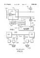
- FIG. 1is a schematic of a power distribution network and a radio-frequency system in accordance with the present invention.
- FIG. 2is a representation of a prior art communications system using the power network.
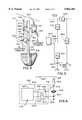
- FIG. 3is an illustration of a coupler in accordance with the present invention.
- FIG. 4is a detailed illustration of an embodiment of a radio-frequency coupler in accordance with the present invention.
- FIG. 5is an equivalent circuit an embodiment of a radio-frequency coupler in accordance with the present invention.
- An electrical power networkis comprised of generators, transformers, transmission lines, and other components.
- a power distribution networkis a part of an electrical power network that couples electrical energy to customers.
- FIG. 1illustrates a power distribution network having additional components serving to provide for two-way high-speed data transfers.
- a transmission network 100furnishes a transmission voltage, typically 69 Kilovolts ("KV") or greater, to a transmission transformer 105, at a distribution substation 110, for converting the transmission voltage to a distribution voltage, typically around 4 to 15 KV.
- KVKilovolts
- the distribution voltageis then distributed as electrical energy over distribution cables 115 to a customer premise 120.
- the distribution cablesare typically three cables, where each cable has one phase of a three phase voltage system.
- Each phase of the distribution voltageis reduced to approximately 120 volts by the step-down action of a distribution transformer 130 for delivery to the customer premise.
- the voltage at the customer premisesuch as a residence, is typically a three-wire single phase voltage and is coupled to the customer premise over a residential cable having three electrical wires 122.
- the voltage delivered over the three electrical wires 122is coupled to a distribution box 140.
- the distribution boxhas circuit breakers and terminals for distributing electrical power within the residence. The sole use of the power distribution network, not having the additional elements, is to deliver electrical power to the customer premise.
- a head-end device 150coupled to a gateway 160 by a converter 170.
- a converter cable 174 and the distribution cable 115are elements in the coupling.
- the converter cable 174may be an optical fiber, a coaxial cable, a twisted pair or other conductors.
- the head-end device 150transmits and receives radio-frequency ("RF") signals to and from the gateway 160.
- RFradio-frequency
- the head-end device 150 and the gateway 160serve as components of an interactive broadband system (“IBS").
- IBSinteractive broadband system
- Elements connected within the customer premise 120 to the gateway 160may include a telephone, a computer, a television, a security system and other such devices.
- the types of services that may be delivered over the IBSare numerous and have been described in public literature, such as trade magazines, technical society journals, internet sites, and other sources. It is the objective of the present invention to provide a communication system that meets existing and future communication needs of IBS providers and customers. Another objective of the present invention is to provide an IBS that efficiently uses elements of the power system as elements of a communications system. Still another object of the present invention is to provide a system that is expandable without the requirement of installing coaxial cable, fiber, or other transmission channel elements.
- the system for providing data communication service to the customer premise as shown in FIG. 1may be modified to provide station-to-station communications for internal use of a power company.
- the data communication system of the present inventionmay serve as part of a control and monitoring system for a power network or power grid.
- additional system elementsmay be needed, such as blocking elements to cancel the interference problems in a hub arrangement and RF repeaters to boost signal levels.
- FIG. 2illustrates a power network communication system 200, a prior art apparatus, that provides phone and data transfer services.
- the power network communication system 200typically referred to as a power line carrier system is used to transfer data between a local station 210, using a power cable 212, and a remote station 214.
- the data rates between the local station 210 and remote station 214 of the power line carrier systemare low compared to the rates for providing IBS.
- a local coupling device 232 and a remote coupling device 242each have a high-voltage terminal connected to the high-voltage power cable 212.
- a second terminal of the coupling devices 232, 242are connected to a local transceiver 233 and a remote transceiver 243.
- the combination of the transceivers, coupling devices, and power cableprovide a low-frequency signal communication system for a telephone connection and an instrument connection.
- the telephone connectionis provided using a local telephone 234 and a remote telephone 244.
- a local monitor and control device 236can transfer and receive information from a remote monitor and control device 246.
- Power line carrier systemshave been used by the power industry for over thirty years and have served to provide for voice communications and low data rate applications.
- the coupling devices 232, 242are typically low-frequency transformers typically passing signals between 30 Hertz and 50 Kilohertz.
- the low-frequency transformersare designed for isolating and protecting personnel and equipment from any overvoltages or high voltage transients that may be present on the high-voltage cables. Because the power line carrier system has met most of the communications and control needs of the power industry there has been little incentive for increasing the bandwidth of such systems. In power system networks requiring higher data bandwidths, power companies have chosen other data transfer means, such as microwave links, dedicated fiber optics, coaxial cables or leased lines.
- the converter 170 for providing broadband servicesis illustrated in FIG. 3.
- the converteris used to transfer a RF signal, typically having frequencies in a one to sixty Megahertz range, between the head-end device 150 and the gateway 160.
- the range of frequencies for RF signals of the present inventionmay be in various regions of the VHF and UHF bands.
- a high-voltage cable 302 of the distribution cable 115is coupled to a single phase distribution transformer 130.
- the distribution transformerprovides single phase, 3 wire power for residential service using power wires 122.
- a transformer grounding terminal 308is coupled to a grounding wire 309 by a heavy gauge copper wire 310. The point where the grounding wire 309 and the transformer grounding wire 310 are coupled is called the neutral node 307.
- the grounding wire 309is secured to a support pole 311 and is attached to a grounding rod 312 at the bottom of the support pole.
- the point where the grounding wire 309 and the grounding rod 312 are coupledis referred to as the ground node 313. All the elements described above are part of a typical electrical connection for providing electrical service to a customer premise 120.
- a lightning arrester 314Also connected to the high-voltage cable 302 is a lightning arrester 314.
- the high-voltage terminal of the arrester 315is connected to the high-voltage cable 302 by an electrical conductor, such as a piece of copper wire.
- the grounding node of the arrester 316is connected to the grounding conductor 309 by another conductor 323, such as a piece of copper wire.
- An RF signaling device 320has an RF output terminal 321 coupled to the grounding node of the arrester 316.
- a RF reference node 322 of the RF signaling device 320is connected to the neutral node 307.
- a head-end device RF transmitted signalis coupled to the RF device 320 using the RF impedance characteristics of the arrester.
- the capacitance of the arresteris large enough to couple an RF signal. It has been determined that the capacitance of an arrester typically has values between 1 picofarad and 170 picofarads. The wide range of values for the capacitance of an arrester is due to the variety of manufacturing techniques and structures.
- FIG. 4illustrates the structure for coupling the RF signaling device 320 to the high-voltage cable 302.
- the RF signaling deviceis comprised of a RF modem 420 coupled to a RF transformer 410.
- a first coupling wire 422 and a second coupling wire 424connect the RF modem to a primary winding 412 of the RF transformer.
- a secondary winding 414 of the RF transformerhas an output terminal 426 connected to the low-voltage terminal of the arrester 316 and a neutral terminal 428 connected to the neutral node 307.
- a ferrite core 430may be placed around the grounding cable. Neither the ferrite core 430 nor the RF transformer 410 is required in order to couple the RF modem 420 to the arrester 315 in accordance with the present invention. However the RF transformer does serve as protection mechanism by providing an alternate path to ground if ground cable 309 is disconnected. In addition the RF transformer may provide impedance matching.
- the arrester 314is used as an element in the coupling apparatus of the present invention, the use of a high-voltage capacitor or other high-voltage RF coupler, such as an adaptive coupler, could serve in place of the arrester.
- the RF couplers of the present inventionwill pass high-frequency signals, but will block low-frequency signals, thereby providing low-frequency isolation.
- An electrical circuit equivalent of the coupling arrangement of FIG. 4is shown in FIG. 5.
- arrestersare considered to be a large impedance to any signal normally found on the high-voltage cable 302, the inventor believes that this novel use of the arrester is unique.
- a modified lightning arrestercould be developed which could serve as an arrester and an RF coupler.
- Such a modified lightning arresterwould result in a novel electrical element having improved coupling characteristics, but could be fabricated or manufactured using methods similar to those used in making existing lightning arresters.
- the grounding cable 309a low impedance to typical power system voltages, may serve as an impedance element for a RF coupling circuit. Because the components of the present invention are installed on existing power distribution networks it may be necessary to add ferrite cores or similar elements to adjust RF impedances. This adjusting of RF impedances is necessary to obtain satisfactory RF coupling.
- the RF modem 420may also transmit a modem transmit signal.
- the modem transmit signalis coupled through the RF transformer 410, the lightning arrester 314, and the high-voltage cable 302 to the head-end device 150.
- the modem transmit signalis used to transfer information to the head-end device 150 from the customer premise. Because the converter 170 transfers RF signals, modulated with data, in both directions, the present invention may be used to provide IBS.
- FIG. 5An equivalent circuit 500 of an embodiment of an RF coupling circuit in accordance with the present invention is illustrated in FIG. 5.
- a translated RF modem 520is an equivalent of the RF modem 420 transformed to the secondary of the RF transformer.
- the output impedance, Z O , 512is the impedance between the bottom of the arrester and the neutral node 307.
- An arrester impedance, Z A , 510is the equivalent impedance of the arrester to an RF signal.
- the line impedance, Z L , 530represents the impedance of the high-voltage cable 302 to an RF signal.
- Connected to one side of the line impedanceis a ground impedance, Z G , 540 representing RF impedance to ground.
- the neutral node 307is coupled to a remote neutral node 552.
- the ground node 313is coupled to a remote ground node 562 by grounding rods driven in the earth.
- a gas discharge tube 564is placed across the terminals of the translated RF modem 520 as a safety device to warn of a faulty circuit.
- the gas discharge tubeacts as an open circuit unless an overvoltage appears across the terminals of the output impedance 512.
- Z A and Z Oserve as a voltage divider circuit. Hence a portion of the RF signal on the high-voltage cable is coupled to the translated RF modem 520. Since only a portion of the incoming RF signal is received by the translated RF modem other converters may receive the RF signal.
- Z A and the combination of Z L and Z Gact as a voltage divider allowing a portion of the modem transmit signal to be received by the head-end device 150.
- the output impedance, Z O , 512serves as a driving point impedance when the RF modem transmits a signal.
- the equivalent circuit of Z O to an RF signalmay be a few microhenries in series with 10 to 30 ohms. Although it is difficult to model Z A , an equivalent impedance of 1 to 150 picofarads in parallel with several megaohms is a workable engineering approximation.
- the equivalent impedance of both Z L and Z Gmay have a very wide range of values, depending on the length of the line and the location and number of distribution connections. In addition to wide variations in the impedances of the equivalent circuit due to the distribution network structure, environmental conditions, such as temperature and humidity may also cause these impedances to change.
- the equivalent circuit 500 as illustrated in FIG. 5may be used by those skilled in the art, applying mesh or nodal analysis in conjunction with transmission line equations, to determine the transmission characteristics of the IBS provided by the present invention.
Landscapes
- Engineering & Computer Science (AREA)
- Power Engineering (AREA)
- Computer Networks & Wireless Communication (AREA)
- Signal Processing (AREA)
- Cable Transmission Systems, Equalization Of Radio And Reduction Of Echo (AREA)
Abstract
Description
Claims (12)
Priority Applications (1)
| Application Number | Priority Date | Filing Date | Title |
|---|---|---|---|
| US08/812,793US5864284A (en) | 1997-03-06 | 1997-03-06 | Apparatus for coupling radio-frequency signals to and from a cable of a power distribution network |
Applications Claiming Priority (1)
| Application Number | Priority Date | Filing Date | Title |
|---|---|---|---|
| US08/812,793US5864284A (en) | 1997-03-06 | 1997-03-06 | Apparatus for coupling radio-frequency signals to and from a cable of a power distribution network |
Publications (1)
| Publication Number | Publication Date |
|---|---|
| US5864284Atrue US5864284A (en) | 1999-01-26 |
Family
ID=25210647
Family Applications (1)
| Application Number | Title | Priority Date | Filing Date |
|---|---|---|---|
| US08/812,793Expired - LifetimeUS5864284A (en) | 1997-03-06 | 1997-03-06 | Apparatus for coupling radio-frequency signals to and from a cable of a power distribution network |
Country Status (1)
| Country | Link |
|---|---|
| US (1) | US5864284A (en) |
Cited By (94)
| Publication number | Priority date | Publication date | Assignee | Title |
|---|---|---|---|---|
| US20020002040A1 (en)* | 2000-04-19 | 2002-01-03 | Kline Paul A. | Method and apparatus for interfacing RF signals to medium voltage power lines |
| US20020097953A1 (en)* | 2000-12-15 | 2002-07-25 | Kline Paul A. | Interfacing fiber optic data with electrical power systems |
| US20020118101A1 (en)* | 2001-02-14 | 2002-08-29 | Kline Paul A. | Data communication over a power line |
| US6452482B1 (en) | 1999-12-30 | 2002-09-17 | Ambient Corporation | Inductive coupling of a data signal to a power transmission cable |
| US20020152320A1 (en)* | 2001-02-14 | 2002-10-17 | Lau Pui Lun | System and method for rapidly switching between redundant networks |
| US6492897B1 (en) | 2000-08-04 | 2002-12-10 | Richard A. Mowery, Jr. | System for coupling wireless signals to and from a power transmission line communication system |
| US6496104B2 (en) | 2000-03-15 | 2002-12-17 | Current Technologies, L.L.C. | System and method for communication via power lines using ultra-short pulses |
| US20030005450A1 (en)* | 2001-07-01 | 2003-01-02 | Gordon Smith | Method and system for connecting high speed data communication signals to a residentual gateway |
| US20030039257A1 (en)* | 2001-08-04 | 2003-02-27 | Manis Constantine N. | Network-to-network adaptor for power line communications |
| US20030071719A1 (en)* | 2001-10-02 | 2003-04-17 | Crenshaw Ralph E. | Method and apparatus for attaching power line communications to customer premises |
| US20030169155A1 (en)* | 2000-04-14 | 2003-09-11 | Mollenkopf James Douglas | Power line communication system and method of using the same |
| US20030179080A1 (en)* | 2001-12-21 | 2003-09-25 | Mollenkopf James Douglas | Facilitating communication of data signals on electric power systems |
| US20030190110A1 (en)* | 2001-02-14 | 2003-10-09 | Kline Paul A. | Method and apparatus for providing inductive coupling and decoupling of high-frequency, high-bandwidth data signals directly on and off of a high voltage power line |
| US20030224784A1 (en)* | 2002-05-28 | 2003-12-04 | Amperion, Inc. | Communications system for providing broadband communications using a medium voltage cable of a power system |
| US20030234713A1 (en)* | 2002-06-21 | 2003-12-25 | Pridmore Charles Franklin | Power line coupling device and method of using the same |
| US6671501B1 (en)* | 1999-04-30 | 2003-12-30 | Polytrax Information Technology | Signal transmission circuit |
| US6683531B2 (en) | 2000-05-04 | 2004-01-27 | Trench Limited | Coupling device for providing a communications link for RF broadband data signals to a power line and method for installing same |
| US20040022304A1 (en)* | 2002-06-21 | 2004-02-05 | John Santhoff | Ultra-wideband communication though local power lines |
| US20040047335A1 (en)* | 2002-06-21 | 2004-03-11 | Proctor James Arthur | Wireless local area network extension using existing wiring and wireless repeater module(s) |
| US20040056734A1 (en)* | 2001-05-18 | 2004-03-25 | Davidow Clifford A. | Medium voltage signal coupling structure for last leg power grid high-speed data network |
| US20040067745A1 (en)* | 2002-10-02 | 2004-04-08 | Amperion, Inc. | Method and system for signal repeating in powerline communications |
| US20040090353A1 (en)* | 2002-11-12 | 2004-05-13 | Moore Steven A. | Ultra-wideband pulse modulation system and method |
| US20040110483A1 (en)* | 2002-12-10 | 2004-06-10 | Mollenkopf James Douglas | Power line communication sytem and method |
| US20040113757A1 (en)* | 2002-12-10 | 2004-06-17 | White Melvin Joseph | Power line communication system and method of operating the same |
| US20040113756A1 (en)* | 2002-12-10 | 2004-06-17 | Mollenkopf James Douglas | Device and method for coupling with electrical distribution network infrastructure to provide communications |
| US20040135676A1 (en)* | 2002-12-10 | 2004-07-15 | Berkman William H. | Power line communication system and method of operating the same |
| US20040142599A1 (en)* | 2003-01-21 | 2004-07-22 | Cope Leonard D. | Power line coupling device and method of using the same |
| US20040141561A1 (en)* | 2002-06-21 | 2004-07-22 | John Santhoff | Ultra-wideband communication through twisted-pair wire media |
| US20040149868A1 (en)* | 2003-01-31 | 2004-08-05 | Schultz David J. | Support for network interface devices |
| US6782048B2 (en) | 2002-06-21 | 2004-08-24 | Pulse-Link, Inc. | Ultra-wideband communication through a wired network |
| US6809633B2 (en) | 2001-03-29 | 2004-10-26 | Ambient Corporation | Coupling broadband modems to power lines |
| US20040218688A1 (en)* | 2002-06-21 | 2004-11-04 | John Santhoff | Ultra-wideband communication through a power grid |
| US20040227623A1 (en)* | 2003-05-07 | 2004-11-18 | Telkonet, Inc. | Network topology and packet routing method using low voltage power wiring |
| US20040227621A1 (en)* | 2000-04-14 | 2004-11-18 | Cope Leonard D. | Power line communication apparatus and method of using the same |
| US20040227622A1 (en)* | 2003-05-13 | 2004-11-18 | Giannini Paul M. | Device and method for communicating data signals through multiple power line conductors |
| US20040233928A1 (en)* | 2003-05-07 | 2004-11-25 | Telkonet, Inc. | Network topology and packet routing method using low voltage power wiring |
| US6831945B1 (en) | 2000-06-16 | 2004-12-14 | Verizon Corporate Services Group Inc. | Method and apparatus for remote identification of transmission channel interference |
| US20050046550A1 (en)* | 2001-10-02 | 2005-03-03 | Crenshaw Ralph E. | Method and apparatus for attaching power line communications to customer premises |
| US20050062589A1 (en)* | 1999-12-30 | 2005-03-24 | Ambient Corporation | Arrangement of inductive couplers for data communication |
| US20050100043A1 (en)* | 2000-04-19 | 2005-05-12 | Serconet Ltd | Network combining wired and non-wired segments |
| US6895034B2 (en) | 2002-07-02 | 2005-05-17 | Pulse-Link, Inc. | Ultra-wideband pulse generation system and method |
| WO2005064562A1 (en)* | 2003-12-24 | 2005-07-14 | Sodiff E & T Co., Ltd | Multi-function electric power supply automation system that use plc modem |
| US6977578B2 (en) | 2000-01-20 | 2005-12-20 | Current Technologies, Llc | Method of isolating data in a power line communications network |
| US6980089B1 (en) | 2000-08-09 | 2005-12-27 | Current Technologies, Llc | Non-intrusive coupling to shielded power cable |
| US6982611B2 (en) | 2002-06-24 | 2006-01-03 | Current Technologies, Llc | Power line coupling device and method of using the same |
| US20060087382A1 (en)* | 2004-10-25 | 2006-04-27 | Ambient Corporation | Inductive coupler for power line communications |
| US20060114925A1 (en)* | 2004-12-01 | 2006-06-01 | At&T Corp. | Interference control in a broadband powerline communication system |
| US20060125609A1 (en)* | 2000-08-09 | 2006-06-15 | Kline Paul A | Power line coupling device and method of using the same |
| US7076378B1 (en) | 2002-11-13 | 2006-07-11 | Current Technologies, Llc | Device and method for providing power line characteristics and diagnostics |
| US20060152344A1 (en)* | 2002-12-07 | 2006-07-13 | Mowery Richard A Jr | Powerline Communication Network Handoff |
| US7091849B1 (en) | 2004-05-06 | 2006-08-15 | At&T Corp. | Inbound interference reduction in a broadband powerline system |
| US7099368B2 (en) | 2002-06-21 | 2006-08-29 | Pulse-Link, Inc. | Ultra-wideband communication through a wire medium |
| US20060193313A1 (en)* | 2005-02-25 | 2006-08-31 | Telkonet, Inc. | Local area network above telephony infrastructure |
| US20060193310A1 (en)* | 2005-02-25 | 2006-08-31 | Telkonet, Inc. | Local area network above telephony methods and devices |
| US20060193336A1 (en)* | 2005-02-25 | 2006-08-31 | Telkonet, Inc. | Local area network above cable television methods and devices |
| US20060203981A1 (en)* | 2000-03-20 | 2006-09-14 | Serconet Ltd. | Telephone outlet for implementing a local area network over telephone lines and a local area network using such outlets |
| US7113134B1 (en) | 2004-03-12 | 2006-09-26 | Current Technologies, Llc | Transformer antenna device and method of using the same |
| US20060244571A1 (en)* | 2005-04-29 | 2006-11-02 | Yaney David S | Power line coupling device and method of use |
| US7132819B1 (en) | 2002-11-12 | 2006-11-07 | Current Technologies, Llc | Floating power supply and method of using the same |
| US20060291546A1 (en)* | 2005-06-28 | 2006-12-28 | International Broadband Electric Communications, Inc. | Device and method for enabling communications signals using a medium voltage power line |
| US20060290476A1 (en)* | 2005-06-28 | 2006-12-28 | International Broadband Electric Communications, Inc. | Improved Coupling of Communications Signals to a Power Line |
| US7199699B1 (en) | 2002-02-19 | 2007-04-03 | Current Technologies, Llc | Facilitating communication with power line communication devices |
| WO2007011543A3 (en)* | 2005-07-15 | 2007-04-19 | Internat Broadband Electric Co | Improved coupling of communications signals to a power line |
| US20070153836A1 (en)* | 2003-03-13 | 2007-07-05 | Serconet, Ltd. | Telephone system having multiple distinct sources and accessories therefor |
| US7245201B1 (en) | 2000-08-09 | 2007-07-17 | Current Technologies, Llc | Power line coupling device and method of using the same |
| US20070178850A1 (en)* | 2006-01-31 | 2007-08-02 | Amperion, Inc. | Radio frequency signal coupling system |
| US7308103B2 (en) | 2003-05-08 | 2007-12-11 | Current Technologies, Llc | Power line communication device and method of using the same |
| US20080063039A1 (en)* | 2002-06-21 | 2008-03-13 | John Santhoff | Optimization of ultra-wideband communication through a wire medium |
| US20080100403A1 (en)* | 2006-10-26 | 2008-05-01 | Cooper Technologies Company | Communications interface accessory for power system arrester |
| USRE40492E1 (en) | 2000-02-10 | 2008-09-09 | Telkonet Communications, Inc. | Power line telephony exchange |
| US20080219326A1 (en)* | 2007-03-09 | 2008-09-11 | John Santhoff | Wireless multimedia link |
| US20080231111A1 (en)* | 2004-02-16 | 2008-09-25 | Serconet Ltd. | Outlet add-on module |
| US7460467B1 (en) | 2003-07-23 | 2008-12-02 | Current Technologies, Llc | Voice-over-IP network test device and method |
| US20080297327A1 (en)* | 2005-07-15 | 2008-12-04 | International Broadband Electric Communications, Inc. | Coupling of Communications Signals to a Power Line |
| US20090002137A1 (en)* | 2007-06-26 | 2009-01-01 | Radtke William O | Power Line Coupling Device and Method |
| US20090002094A1 (en)* | 2007-06-26 | 2009-01-01 | Radtke William O | Power Line Coupling Device and Method |
| US20090058185A1 (en)* | 2007-08-31 | 2009-03-05 | Optimal Innovations Inc. | Intelligent Infrastructure Power Supply Control System |
| US20090085726A1 (en)* | 2007-09-27 | 2009-04-02 | Radtke William O | Power Line Communications Coupling Device and Method |
| US20090198795A1 (en)* | 2004-01-13 | 2009-08-06 | Yehuda Binder | Information device |
| US7573891B1 (en)* | 2001-12-05 | 2009-08-11 | Optimal Innovations, Inc. | Hybrid fiber/conductor integrated communication networks |
| US7667344B2 (en) | 2005-07-15 | 2010-02-23 | International Broadband Electric Communications, Inc. | Coupling communications signals to underground power lines |
| US7813451B2 (en) | 2006-01-11 | 2010-10-12 | Mobileaccess Networks Ltd. | Apparatus and method for frequency shifting of a wireless signal and systems using frequency shifting |
| US7852837B1 (en) | 2003-12-24 | 2010-12-14 | At&T Intellectual Property Ii, L.P. | Wi-Fi/BPL dual mode repeaters for power line networks |
| US7852874B2 (en) | 1998-07-28 | 2010-12-14 | Mosaid Technologies Incorporated | Local area network of serial intelligent cells |
| US7873058B2 (en) | 2004-11-08 | 2011-01-18 | Mosaid Technologies Incorporated | Outlet with analog signal adapter, a method for use thereof and a network using said outlet |
| US7990908B2 (en) | 2002-11-13 | 2011-08-02 | Mosaid Technologies Incorporated | Addressable outlet, and a network using the same |
| US8175649B2 (en) | 2008-06-20 | 2012-05-08 | Corning Mobileaccess Ltd | Method and system for real time control of an active antenna over a distributed antenna system |
| US8325759B2 (en) | 2004-05-06 | 2012-12-04 | Corning Mobileaccess Ltd | System and method for carrying a wireless based signal over wiring |
| US8462902B1 (en) | 2004-12-01 | 2013-06-11 | At&T Intellectual Property Ii, L.P. | Interference control in a broadband powerline communication system |
| US8594133B2 (en) | 2007-10-22 | 2013-11-26 | Corning Mobileaccess Ltd. | Communication system using low bandwidth wires |
| US8897215B2 (en) | 2009-02-08 | 2014-11-25 | Corning Optical Communications Wireless Ltd | Communication system using cables carrying ethernet signals |
| US9184960B1 (en) | 2014-09-25 | 2015-11-10 | Corning Optical Communications Wireless Ltd | Frequency shifting a communications signal(s) in a multi-frequency distributed antenna system (DAS) to avoid or reduce frequency interference |
| US9338823B2 (en) | 2012-03-23 | 2016-05-10 | Corning Optical Communications Wireless Ltd | Radio-frequency integrated circuit (RFIC) chip(s) for providing distributed antenna system functionalities, and related components, systems, and methods |
| JP2016142520A (en)* | 2015-01-29 | 2016-08-08 | 中国電力株式会社 | Terminal device for grounding |
Citations (5)
| Publication number | Priority date | Publication date | Assignee | Title |
|---|---|---|---|---|
| US4142178A (en)* | 1977-04-25 | 1979-02-27 | Westinghouse Electric Corp. | High voltage signal coupler for a distribution network power line carrier communication system |
| US4361202A (en)* | 1979-06-15 | 1982-11-30 | Michael Minovitch | Automated road transportation system |
| US4471399A (en)* | 1982-03-11 | 1984-09-11 | Westinghouse Electric Corp. | Power-line baseband communication system |
| US4668934A (en)* | 1984-10-22 | 1987-05-26 | Westinghouse Electric Corp. | Receiver apparatus for three-phase power line carrier communications |
| US4851832A (en)* | 1986-10-06 | 1989-07-25 | Herbert Graf | Traffic control device for street vehicles |
- 1997
- 1997-03-06USUS08/812,793patent/US5864284A/ennot_activeExpired - Lifetime
Patent Citations (5)
| Publication number | Priority date | Publication date | Assignee | Title |
|---|---|---|---|---|
| US4142178A (en)* | 1977-04-25 | 1979-02-27 | Westinghouse Electric Corp. | High voltage signal coupler for a distribution network power line carrier communication system |
| US4361202A (en)* | 1979-06-15 | 1982-11-30 | Michael Minovitch | Automated road transportation system |
| US4471399A (en)* | 1982-03-11 | 1984-09-11 | Westinghouse Electric Corp. | Power-line baseband communication system |
| US4668934A (en)* | 1984-10-22 | 1987-05-26 | Westinghouse Electric Corp. | Receiver apparatus for three-phase power line carrier communications |
| US4851832A (en)* | 1986-10-06 | 1989-07-25 | Herbert Graf | Traffic control device for street vehicles |
Cited By (208)
| Publication number | Priority date | Publication date | Assignee | Title |
|---|---|---|---|---|
| US8885659B2 (en) | 1998-07-28 | 2014-11-11 | Conversant Intellectual Property Management Incorporated | Local area network of serial intelligent cells |
| US8885660B2 (en) | 1998-07-28 | 2014-11-11 | Conversant Intellectual Property Management Incorporated | Local area network of serial intelligent cells |
| US7978726B2 (en) | 1998-07-28 | 2011-07-12 | Mosaid Technologies Incorporated | Local area network of serial intelligent cells |
| US7852874B2 (en) | 1998-07-28 | 2010-12-14 | Mosaid Technologies Incorporated | Local area network of serial intelligent cells |
| US8908673B2 (en) | 1998-07-28 | 2014-12-09 | Conversant Intellectual Property Management Incorporated | Local area network of serial intelligent cells |
| US8867523B2 (en) | 1998-07-28 | 2014-10-21 | Conversant Intellectual Property Management Incorporated | Local area network of serial intelligent cells |
| US6671501B1 (en)* | 1999-04-30 | 2003-12-30 | Polytrax Information Technology | Signal transmission circuit |
| US6452482B1 (en) | 1999-12-30 | 2002-09-17 | Ambient Corporation | Inductive coupling of a data signal to a power transmission cable |
| US7154382B2 (en) | 1999-12-30 | 2006-12-26 | Ambient Corporation | Arrangement of inductive couplers for data communication |
| US6646447B2 (en) | 1999-12-30 | 2003-11-11 | Ambient Corporation | Identifying one of a plurality of wires of a power transmission cable |
| US20030160684A1 (en)* | 1999-12-30 | 2003-08-28 | Ambient Corporation | Inductive coupling of a data signal for a power transmission cable |
| US20050062589A1 (en)* | 1999-12-30 | 2005-03-24 | Ambient Corporation | Arrangement of inductive couplers for data communication |
| US6897764B2 (en) | 1999-12-30 | 2005-05-24 | Ambient Corporation | Inductive coupling of a data signal for a power transmission cable |
| US6977578B2 (en) | 2000-01-20 | 2005-12-20 | Current Technologies, Llc | Method of isolating data in a power line communications network |
| USRE40492E1 (en) | 2000-02-10 | 2008-09-09 | Telkonet Communications, Inc. | Power line telephony exchange |
| US6496104B2 (en) | 2000-03-15 | 2002-12-17 | Current Technologies, L.L.C. | System and method for communication via power lines using ultra-short pulses |
| US20060203981A1 (en)* | 2000-03-20 | 2006-09-14 | Serconet Ltd. | Telephone outlet for implementing a local area network over telephone lines and a local area network using such outlets |
| US7715534B2 (en) | 2000-03-20 | 2010-05-11 | Mosaid Technologies Incorporated | Telephone outlet for implementing a local area network over telephone lines and a local area network using such outlets |
| US8363797B2 (en) | 2000-03-20 | 2013-01-29 | Mosaid Technologies Incorporated | Telephone outlet for implementing a local area network over telephone lines and a local area network using such outlets |
| US8855277B2 (en) | 2000-03-20 | 2014-10-07 | Conversant Intellectual Property Managment Incorporated | Telephone outlet for implementing a local area network over telephone lines and a local area network using such outlets |
| US7245212B2 (en) | 2000-04-14 | 2007-07-17 | Current Technologies, Llc | Power line communication apparatus and method of using the same |
| US6998962B2 (en) | 2000-04-14 | 2006-02-14 | Current Technologies, Llc | Power line communication apparatus and method of using the same |
| US20030169155A1 (en)* | 2000-04-14 | 2003-09-11 | Mollenkopf James Douglas | Power line communication system and method of using the same |
| US20050285720A1 (en)* | 2000-04-14 | 2005-12-29 | Cope Leonard D | Power line communication apparatus and method of using the same |
| US6965302B2 (en) | 2000-04-14 | 2005-11-15 | Current Technologies, Llc | Power line communication system and method of using the same |
| US20040227621A1 (en)* | 2000-04-14 | 2004-11-18 | Cope Leonard D. | Power line communication apparatus and method of using the same |
| US20050100043A1 (en)* | 2000-04-19 | 2005-05-12 | Serconet Ltd | Network combining wired and non-wired segments |
| US8982904B2 (en) | 2000-04-19 | 2015-03-17 | Conversant Intellectual Property Management Inc. | Network combining wired and non-wired segments |
| US8873575B2 (en) | 2000-04-19 | 2014-10-28 | Conversant Intellectual Property Management Incorporated | Network combining wired and non-wired segments |
| US8873586B2 (en) | 2000-04-19 | 2014-10-28 | Conversant Intellectual Property Management Incorporated | Network combining wired and non-wired segments |
| US8848725B2 (en) | 2000-04-19 | 2014-09-30 | Conversant Intellectual Property Management Incorporated | Network combining wired and non-wired segments |
| US20020002040A1 (en)* | 2000-04-19 | 2002-01-03 | Kline Paul A. | Method and apparatus for interfacing RF signals to medium voltage power lines |
| US8289991B2 (en) | 2000-04-19 | 2012-10-16 | Mosaid Technologies Incorporated | Network combining wired and non-wired segments |
| US7636373B2 (en) | 2000-04-19 | 2009-12-22 | Mosaid Technologies Incorporated | Network combining wired and non-wired segments |
| US7933297B2 (en) | 2000-04-19 | 2011-04-26 | Mosaid Technologies Incorporated | Network combining wired and non-wired segments |
| US7876767B2 (en) | 2000-04-19 | 2011-01-25 | Mosaid Technologies Incorporated | Network combining wired and non-wired segments |
| US8982903B2 (en) | 2000-04-19 | 2015-03-17 | Conversant Intellectual Property Management Inc. | Network combining wired and non-wired segments |
| US7633966B2 (en) | 2000-04-19 | 2009-12-15 | Mosaid Technologies Incorporated | Network combining wired and non-wired segments |
| US8867506B2 (en) | 2000-04-19 | 2014-10-21 | Conversant Intellectual Property Management Incorporated | Network combining wired and non-wired segments |
| US20100135479A1 (en)* | 2000-04-19 | 2010-06-03 | Mosaid Technologies Incorporated | Network combining wired and non-wired segments |
| US20050232299A1 (en)* | 2000-04-19 | 2005-10-20 | Serconet, Ltd. | Network combining wired and non-wired segments |
| US20100135191A1 (en)* | 2000-04-19 | 2010-06-03 | Mosaid Technologies Incorporated | Network Combining Wired and Non-Wired Segments |
| US20100135480A1 (en)* | 2000-04-19 | 2010-06-03 | Mosaid Technologies Incorporated | Network combining wired and non-wired segments |
| US20050254516A1 (en)* | 2000-04-19 | 2005-11-17 | Serconet, Ltd. | Network combining wired and non-wired segments |
| US20050259691A1 (en)* | 2000-04-19 | 2005-11-24 | Serconet Ltd | Network combining wired and non-wired segments |
| US7715441B2 (en) | 2000-04-19 | 2010-05-11 | Mosaid Technologies Incorporated | Network combining wired and non-wired segments |
| US6683531B2 (en) | 2000-05-04 | 2004-01-27 | Trench Limited | Coupling device for providing a communications link for RF broadband data signals to a power line and method for installing same |
| US6831945B1 (en) | 2000-06-16 | 2004-12-14 | Verizon Corporate Services Group Inc. | Method and apparatus for remote identification of transmission channel interference |
| US6492897B1 (en) | 2000-08-04 | 2002-12-10 | Richard A. Mowery, Jr. | System for coupling wireless signals to and from a power transmission line communication system |
| US7248148B2 (en)* | 2000-08-09 | 2007-07-24 | Current Technologies, Llc | Power line coupling device and method of using the same |
| US7245201B1 (en) | 2000-08-09 | 2007-07-17 | Current Technologies, Llc | Power line coupling device and method of using the same |
| US6980089B1 (en) | 2000-08-09 | 2005-12-27 | Current Technologies, Llc | Non-intrusive coupling to shielded power cable |
| US20060125609A1 (en)* | 2000-08-09 | 2006-06-15 | Kline Paul A | Power line coupling device and method of using the same |
| US20020097953A1 (en)* | 2000-12-15 | 2002-07-25 | Kline Paul A. | Interfacing fiber optic data with electrical power systems |
| EP1371219A4 (en)* | 2001-02-14 | 2006-06-21 | Current Tech Llc | Data communication over a power line |
| US20020152320A1 (en)* | 2001-02-14 | 2002-10-17 | Lau Pui Lun | System and method for rapidly switching between redundant networks |
| US7103240B2 (en) | 2001-02-14 | 2006-09-05 | Current Technologies, Llc | Method and apparatus for providing inductive coupling and decoupling of high-frequency, high-bandwidth data signals directly on and off of a high voltage power line |
| US7453352B2 (en) | 2001-02-14 | 2008-11-18 | Current Technologies, Llc | Data communication over a power line |
| US6950567B2 (en) | 2001-02-14 | 2005-09-27 | Current Technologies, Llc | Method and apparatus for providing inductive coupling and decoupling of high-frequency, high-bandwidth data signals directly on and off of a high voltage power line |
| US20030190110A1 (en)* | 2001-02-14 | 2003-10-09 | Kline Paul A. | Method and apparatus for providing inductive coupling and decoupling of high-frequency, high-bandwidth data signals directly on and off of a high voltage power line |
| US20020121963A1 (en)* | 2001-02-14 | 2002-09-05 | Kline Paul A. | Data communication over a power line |
| WO2002065684A3 (en)* | 2001-02-14 | 2002-09-26 | Current Technologies L L C | Data communication over a power line |
| US7042351B2 (en) | 2001-02-14 | 2006-05-09 | Current Technologies, Llc | Data communication over a power line |
| US6933835B2 (en) | 2001-02-14 | 2005-08-23 | Current Technologies, Llc | Data communication over a power line |
| US20020118101A1 (en)* | 2001-02-14 | 2002-08-29 | Kline Paul A. | Data communication over a power line |
| US7414518B2 (en) | 2001-02-14 | 2008-08-19 | Current Technologies, Llc | Power line communication device and method |
| US20060171174A1 (en)* | 2001-02-14 | 2006-08-03 | Kline Paul A | Data communication over a power line |
| US20070287406A1 (en)* | 2001-02-14 | 2007-12-13 | Kline Paul A | Data Communication over a Power Line |
| US7218219B2 (en) | 2001-02-14 | 2007-05-15 | Current Technologies, Llc | Data communication over a power line |
| US6809633B2 (en) | 2001-03-29 | 2004-10-26 | Ambient Corporation | Coupling broadband modems to power lines |
| US20040056734A1 (en)* | 2001-05-18 | 2004-03-25 | Davidow Clifford A. | Medium voltage signal coupling structure for last leg power grid high-speed data network |
| US7773361B2 (en) | 2001-05-18 | 2010-08-10 | Current Grid, Llc | Medium voltage signal coupling structure for last leg power grid high-speed data network |
| US7245472B2 (en) | 2001-05-18 | 2007-07-17 | Curretn Grid, Llc | Medium voltage signal coupling structure for last leg power grid high-speed data network |
| US20070222637A1 (en)* | 2001-05-18 | 2007-09-27 | Davidow Clifford A | Medium Voltage Signal Coupling Structure For Last Leg Power Grid High-Speed Data Network |
| US20030005450A1 (en)* | 2001-07-01 | 2003-01-02 | Gordon Smith | Method and system for connecting high speed data communication signals to a residentual gateway |
| US7245625B2 (en)* | 2001-08-04 | 2007-07-17 | Arkados, Inc. | Network-to-network adaptor for power line communications |
| US20030039257A1 (en)* | 2001-08-04 | 2003-02-27 | Manis Constantine N. | Network-to-network adaptor for power line communications |
| US20050253690A1 (en)* | 2001-10-02 | 2005-11-17 | Telkonet Communications, Inc. | Method and apparatus for attaching power line communications to customer premises |
| US6975212B2 (en) | 2001-10-02 | 2005-12-13 | Telkonet Communications, Inc. | Method and apparatus for attaching power line communications to customer premises |
| US7091831B2 (en) | 2001-10-02 | 2006-08-15 | Telkonet Communications, Inc. | Method and apparatus for attaching power line communications to customer premises |
| US20050046550A1 (en)* | 2001-10-02 | 2005-03-03 | Crenshaw Ralph E. | Method and apparatus for attaching power line communications to customer premises |
| US20030071719A1 (en)* | 2001-10-02 | 2003-04-17 | Crenshaw Ralph E. | Method and apparatus for attaching power line communications to customer premises |
| US20050248441A1 (en)* | 2001-10-02 | 2005-11-10 | Telkonet Communications, Inc. | Method and apparatus for attaching power line communications to customer premises |
| US7573891B1 (en)* | 2001-12-05 | 2009-08-11 | Optimal Innovations, Inc. | Hybrid fiber/conductor integrated communication networks |
| US7053756B2 (en) | 2001-12-21 | 2006-05-30 | Current Technologies, Llc | Facilitating communication of data signals on electric power systems |
| US20030179080A1 (en)* | 2001-12-21 | 2003-09-25 | Mollenkopf James Douglas | Facilitating communication of data signals on electric power systems |
| US7199699B1 (en) | 2002-02-19 | 2007-04-03 | Current Technologies, Llc | Facilitating communication with power line communication devices |
| US20030224784A1 (en)* | 2002-05-28 | 2003-12-04 | Amperion, Inc. | Communications system for providing broadband communications using a medium voltage cable of a power system |
| US6885674B2 (en) | 2002-05-28 | 2005-04-26 | Amperion, Inc. | Communications system for providing broadband communications using a medium voltage cable of a power system |
| US7167525B2 (en) | 2002-06-21 | 2007-01-23 | Pulse-Link, Inc. | Ultra-wideband communication through twisted-pair wire media |
| US7027483B2 (en) | 2002-06-21 | 2006-04-11 | Pulse-Link, Inc. | Ultra-wideband communication through local power lines |
| US20040022304A1 (en)* | 2002-06-21 | 2004-02-05 | John Santhoff | Ultra-wideband communication though local power lines |
| US7486742B2 (en) | 2002-06-21 | 2009-02-03 | Pulse-Link, Inc. | Optimization of ultra-wideband communication through a wire medium |
| US7102478B2 (en) | 2002-06-21 | 2006-09-05 | Current Technologies, Llc | Power line coupling device and method of using the same |
| US20040047335A1 (en)* | 2002-06-21 | 2004-03-11 | Proctor James Arthur | Wireless local area network extension using existing wiring and wireless repeater module(s) |
| US7099368B2 (en) | 2002-06-21 | 2006-08-29 | Pulse-Link, Inc. | Ultra-wideband communication through a wire medium |
| US6782048B2 (en) | 2002-06-21 | 2004-08-24 | Pulse-Link, Inc. | Ultra-wideband communication through a wired network |
| US20070116097A1 (en)* | 2002-06-21 | 2007-05-24 | John Santhoff | Ultra-wideband communication through twisted-pair wire media |
| US20040218688A1 (en)* | 2002-06-21 | 2004-11-04 | John Santhoff | Ultra-wideband communication through a power grid |
| US20040141561A1 (en)* | 2002-06-21 | 2004-07-22 | John Santhoff | Ultra-wideband communication through twisted-pair wire media |
| US20030234713A1 (en)* | 2002-06-21 | 2003-12-25 | Pridmore Charles Franklin | Power line coupling device and method of using the same |
| US20080063039A1 (en)* | 2002-06-21 | 2008-03-13 | John Santhoff | Optimization of ultra-wideband communication through a wire medium |
| US6982611B2 (en) | 2002-06-24 | 2006-01-03 | Current Technologies, Llc | Power line coupling device and method of using the same |
| US20060012449A1 (en)* | 2002-06-24 | 2006-01-19 | Cope Leonard D | Power line coupling device and method of using the same |
| US7224243B2 (en) | 2002-06-24 | 2007-05-29 | Current Technologies, Llc | Power line coupling device and method of using the same |
| US6895034B2 (en) | 2002-07-02 | 2005-05-17 | Pulse-Link, Inc. | Ultra-wideband pulse generation system and method |
| US6993317B2 (en) | 2002-10-02 | 2006-01-31 | Amperion, Inc. | Method and system for signal repeating in powerline communications |
| US20040067745A1 (en)* | 2002-10-02 | 2004-04-08 | Amperion, Inc. | Method and system for signal repeating in powerline communications |
| US7132819B1 (en) | 2002-11-12 | 2006-11-07 | Current Technologies, Llc | Floating power supply and method of using the same |
| US6836223B2 (en) | 2002-11-12 | 2004-12-28 | Pulse-Link, Inc. | Ultra-wideband pulse modulation system and method |
| US6836226B2 (en) | 2002-11-12 | 2004-12-28 | Pulse-Link, Inc. | Ultra-wideband pulse modulation system and method |
| US6781530B2 (en) | 2002-11-12 | 2004-08-24 | Pulse-Link, Inc. | Ultra-wideband pulse modulation system and method |
| US20040090353A1 (en)* | 2002-11-12 | 2004-05-13 | Moore Steven A. | Ultra-wideband pulse modulation system and method |
| US20040140918A1 (en)* | 2002-11-12 | 2004-07-22 | Moore Steven A. | Ultra-wideband pulse modulation system and method |
| US20040140917A1 (en)* | 2002-11-12 | 2004-07-22 | Moore Steven A. | Ultra-wideband pulse modulation system and method |
| US7990908B2 (en) | 2002-11-13 | 2011-08-02 | Mosaid Technologies Incorporated | Addressable outlet, and a network using the same |
| US7076378B1 (en) | 2002-11-13 | 2006-07-11 | Current Technologies, Llc | Device and method for providing power line characteristics and diagnostics |
| US20060152344A1 (en)* | 2002-12-07 | 2006-07-13 | Mowery Richard A Jr | Powerline Communication Network Handoff |
| US7701325B2 (en) | 2002-12-10 | 2010-04-20 | Current Technologies, Llc | Power line communication apparatus and method of using the same |
| US6965303B2 (en) | 2002-12-10 | 2005-11-15 | Current Technologies, Llc | Power line communication system and method |
| US7250848B2 (en) | 2002-12-10 | 2007-07-31 | Current Technologies, Llc | Power line communication apparatus and method of using the same |
| US6980090B2 (en) | 2002-12-10 | 2005-12-27 | Current Technologies, Llc | Device and method for coupling with electrical distribution network infrastructure to provide communications |
| US7064654B2 (en) | 2002-12-10 | 2006-06-20 | Current Technologies, Llc | Power line communication system and method of operating the same |
| US7301440B2 (en) | 2002-12-10 | 2007-11-27 | Current Technologies, Llc | Power line communication system and method |
| US20040135676A1 (en)* | 2002-12-10 | 2004-07-15 | Berkman William H. | Power line communication system and method of operating the same |
| US6980091B2 (en) | 2002-12-10 | 2005-12-27 | Current Technologies, Llc | Power line communication system and method of operating the same |
| US20040110483A1 (en)* | 2002-12-10 | 2004-06-10 | Mollenkopf James Douglas | Power line communication sytem and method |
| US20050273282A1 (en)* | 2002-12-10 | 2005-12-08 | Mollenkopf James D | Power line communication system and method |
| US20040113757A1 (en)* | 2002-12-10 | 2004-06-17 | White Melvin Joseph | Power line communication system and method of operating the same |
| US20040113756A1 (en)* | 2002-12-10 | 2004-06-17 | Mollenkopf James Douglas | Device and method for coupling with electrical distribution network infrastructure to provide communications |
| US7046124B2 (en) | 2003-01-21 | 2006-05-16 | Current Technologies, Llc | Power line coupling device and method of using the same |
| US20040142599A1 (en)* | 2003-01-21 | 2004-07-22 | Cope Leonard D. | Power line coupling device and method of using the same |
| US20040149868A1 (en)* | 2003-01-31 | 2004-08-05 | Schultz David J. | Support for network interface devices |
| US20070153836A1 (en)* | 2003-03-13 | 2007-07-05 | Serconet, Ltd. | Telephone system having multiple distinct sources and accessories therefor |
| US20040227623A1 (en)* | 2003-05-07 | 2004-11-18 | Telkonet, Inc. | Network topology and packet routing method using low voltage power wiring |
| US20040233928A1 (en)* | 2003-05-07 | 2004-11-25 | Telkonet, Inc. | Network topology and packet routing method using low voltage power wiring |
| US7308103B2 (en) | 2003-05-08 | 2007-12-11 | Current Technologies, Llc | Power line communication device and method of using the same |
| US7075414B2 (en) | 2003-05-13 | 2006-07-11 | Current Technologies, Llc | Device and method for communicating data signals through multiple power line conductors |
| US20040227622A1 (en)* | 2003-05-13 | 2004-11-18 | Giannini Paul M. | Device and method for communicating data signals through multiple power line conductors |
| US7460467B1 (en) | 2003-07-23 | 2008-12-02 | Current Technologies, Llc | Voice-over-IP network test device and method |
| US10728127B2 (en) | 2003-12-24 | 2020-07-28 | At&T Intellectual Property Ii, L.P. | Wi-Fi/BPL dual mode repeaters for power line networks |
| US7852837B1 (en) | 2003-12-24 | 2010-12-14 | At&T Intellectual Property Ii, L.P. | Wi-Fi/BPL dual mode repeaters for power line networks |
| WO2005064562A1 (en)* | 2003-12-24 | 2005-07-14 | Sodiff E & T Co., Ltd | Multi-function electric power supply automation system that use plc modem |
| US20110009077A1 (en)* | 2004-01-13 | 2011-01-13 | May Patents Ltd. | Information device |
| US20090198795A1 (en)* | 2004-01-13 | 2009-08-06 | Yehuda Binder | Information device |
| US7881462B2 (en) | 2004-02-16 | 2011-02-01 | Mosaid Technologies Incorporated | Outlet add-on module |
| US20080231111A1 (en)* | 2004-02-16 | 2008-09-25 | Serconet Ltd. | Outlet add-on module |
| US7113134B1 (en) | 2004-03-12 | 2006-09-26 | Current Technologies, Llc | Transformer antenna device and method of using the same |
| US8325759B2 (en) | 2004-05-06 | 2012-12-04 | Corning Mobileaccess Ltd | System and method for carrying a wireless based signal over wiring |
| US8325693B2 (en) | 2004-05-06 | 2012-12-04 | Corning Mobileaccess Ltd | System and method for carrying a wireless based signal over wiring |
| US10700737B2 (en) | 2004-05-06 | 2020-06-30 | At&T Intellectual Property Ii, L.P. | Outbound interference reduction in a broadband powerline system |
| US10312965B2 (en) | 2004-05-06 | 2019-06-04 | At&T Intellectual Property Ii, L.P. | Outbound interference reduction in a broadband powerline system |
| US8938021B1 (en) | 2004-05-06 | 2015-01-20 | Paul Shala Henry | Outbound interference reduction in a broadband powerline system |
| US9887734B2 (en) | 2004-05-06 | 2018-02-06 | At&T Intellectual Property Ii, L.P. | Outbound interference reduction in a broadband powerline system |
| US7453353B1 (en) | 2004-05-06 | 2008-11-18 | At&T Intellectual Property Ii, L.P. | Inbound interference reduction in a broadband powerline system |
| US9577706B2 (en) | 2004-05-06 | 2017-02-21 | At&T Intellectual Property Ii, L.P. | Outbound interference reduction in a broadband powerline system |
| US7091849B1 (en) | 2004-05-06 | 2006-08-15 | At&T Corp. | Inbound interference reduction in a broadband powerline system |
| US20060087382A1 (en)* | 2004-10-25 | 2006-04-27 | Ambient Corporation | Inductive coupler for power line communications |
| US7170367B2 (en) | 2004-10-25 | 2007-01-30 | Ambient Corporation | Inductive coupler for power line communications |
| US7873058B2 (en) | 2004-11-08 | 2011-01-18 | Mosaid Technologies Incorporated | Outlet with analog signal adapter, a method for use thereof and a network using said outlet |
| US8462902B1 (en) | 2004-12-01 | 2013-06-11 | At&T Intellectual Property Ii, L.P. | Interference control in a broadband powerline communication system |
| US10263666B2 (en) | 2004-12-01 | 2019-04-16 | At&T Intellectual Property Ii, L.P. | Interference control in a broadband powerline communication system |
| US8804797B2 (en) | 2004-12-01 | 2014-08-12 | At&T Intellectual Property Ii, L.P. | Interference control in a broadband powerline communication system |
| US9780835B2 (en) | 2004-12-01 | 2017-10-03 | At&T Intellectual Property Ii, L.P. | Interference control in a broadband powerline communication system |
| US20060114925A1 (en)* | 2004-12-01 | 2006-06-01 | At&T Corp. | Interference control in a broadband powerline communication system |
| US9172429B2 (en) | 2004-12-01 | 2015-10-27 | At&T Intellectual Property Ii, L.P. | Interference control in a broadband powerline communication system |
| US20060193313A1 (en)* | 2005-02-25 | 2006-08-31 | Telkonet, Inc. | Local area network above telephony infrastructure |
| US20060193336A1 (en)* | 2005-02-25 | 2006-08-31 | Telkonet, Inc. | Local area network above cable television methods and devices |
| US20060193310A1 (en)* | 2005-02-25 | 2006-08-31 | Telkonet, Inc. | Local area network above telephony methods and devices |
| US20060244571A1 (en)* | 2005-04-29 | 2006-11-02 | Yaney David S | Power line coupling device and method of use |
| US7307512B2 (en) | 2005-04-29 | 2007-12-11 | Current Technologies, Llc | Power line coupling device and method of use |
| US7414526B2 (en) | 2005-06-28 | 2008-08-19 | International Broadband Communications, Inc. | Coupling of communications signals to a power line |
| US20060290476A1 (en)* | 2005-06-28 | 2006-12-28 | International Broadband Electric Communications, Inc. | Improved Coupling of Communications Signals to a Power Line |
| US7319717B2 (en) | 2005-06-28 | 2008-01-15 | International Broadband Electric Communications, Inc. | Device and method for enabling communications signals using a medium voltage power line |
| US20060291546A1 (en)* | 2005-06-28 | 2006-12-28 | International Broadband Electric Communications, Inc. | Device and method for enabling communications signals using a medium voltage power line |
| WO2007011543A3 (en)* | 2005-07-15 | 2007-04-19 | Internat Broadband Electric Co | Improved coupling of communications signals to a power line |
| US7778514B2 (en) | 2005-07-15 | 2010-08-17 | International Broadband Electric Communications, Inc. | Coupling of communications signals to a power line |
| US7667344B2 (en) | 2005-07-15 | 2010-02-23 | International Broadband Electric Communications, Inc. | Coupling communications signals to underground power lines |
| US7522812B2 (en) | 2005-07-15 | 2009-04-21 | International Broadband Electric Communications, Inc. | Coupling of communications signals to a power line |
| US20080297327A1 (en)* | 2005-07-15 | 2008-12-04 | International Broadband Electric Communications, Inc. | Coupling of Communications Signals to a Power Line |
| US7813451B2 (en) | 2006-01-11 | 2010-10-12 | Mobileaccess Networks Ltd. | Apparatus and method for frequency shifting of a wireless signal and systems using frequency shifting |
| US8184681B2 (en) | 2006-01-11 | 2012-05-22 | Corning Mobileaccess Ltd | Apparatus and method for frequency shifting of a wireless signal and systems using frequency shifting |
| US20110206088A1 (en)* | 2006-01-11 | 2011-08-25 | Mobileaccess Networks Ltd. | Apparatus and method for frequency shifting of a wireless signal and systems using frequency shifting |
| MD3957G2 (en)* | 2006-01-31 | 2010-03-31 | Amperion, Inc. | Radio frequency coupler, coupling system and method |
| US7535685B2 (en) | 2006-01-31 | 2009-05-19 | Amperion, Inc. | Radio frequency signal coupler, coupling system and method |
| US20070178850A1 (en)* | 2006-01-31 | 2007-08-02 | Amperion, Inc. | Radio frequency signal coupling system |
| EP1982427A4 (en)* | 2006-01-31 | 2014-01-08 | Amperion Inc | A radio frequency coupler, coupling system and method |
| WO2007089294A1 (en)* | 2006-01-31 | 2007-08-09 | Amperion Inc | A radio frequency signal coupler, coupling system and method |
| US20080100403A1 (en)* | 2006-10-26 | 2008-05-01 | Cooper Technologies Company | Communications interface accessory for power system arrester |
| US8063767B2 (en) | 2006-10-26 | 2011-11-22 | Cooper Technologies Company | Communications interface accessory for power system arrester |
| US20080219326A1 (en)* | 2007-03-09 | 2008-09-11 | John Santhoff | Wireless multimedia link |
| US7876174B2 (en) | 2007-06-26 | 2011-01-25 | Current Technologies, Llc | Power line coupling device and method |
| US20090002094A1 (en)* | 2007-06-26 | 2009-01-01 | Radtke William O | Power Line Coupling Device and Method |
| US20090002137A1 (en)* | 2007-06-26 | 2009-01-01 | Radtke William O | Power Line Coupling Device and Method |
| US7795994B2 (en) | 2007-06-26 | 2010-09-14 | Current Technologies, Llc | Power line coupling device and method |
| US20090058185A1 (en)* | 2007-08-31 | 2009-03-05 | Optimal Innovations Inc. | Intelligent Infrastructure Power Supply Control System |
| US20090085726A1 (en)* | 2007-09-27 | 2009-04-02 | Radtke William O | Power Line Communications Coupling Device and Method |
| US8594133B2 (en) | 2007-10-22 | 2013-11-26 | Corning Mobileaccess Ltd. | Communication system using low bandwidth wires |
| US9813229B2 (en) | 2007-10-22 | 2017-11-07 | Corning Optical Communications Wireless Ltd | Communication system using low bandwidth wires |
| US9549301B2 (en) | 2007-12-17 | 2017-01-17 | Corning Optical Communications Wireless Ltd | Method and system for real time control of an active antenna over a distributed antenna system |
| US8175649B2 (en) | 2008-06-20 | 2012-05-08 | Corning Mobileaccess Ltd | Method and system for real time control of an active antenna over a distributed antenna system |
| US8897215B2 (en) | 2009-02-08 | 2014-11-25 | Corning Optical Communications Wireless Ltd | Communication system using cables carrying ethernet signals |
| US9948329B2 (en) | 2012-03-23 | 2018-04-17 | Corning Optical Communications Wireless, LTD | Radio-frequency integrated circuit (RFIC) chip(s) for providing distributed antenna system functionalities, and related components, systems, and methods |
| US9338823B2 (en) | 2012-03-23 | 2016-05-10 | Corning Optical Communications Wireless Ltd | Radio-frequency integrated circuit (RFIC) chip(s) for providing distributed antenna system functionalities, and related components, systems, and methods |
| US9515855B2 (en) | 2014-09-25 | 2016-12-06 | Corning Optical Communications Wireless Ltd | Frequency shifting a communications signal(s) in a multi-frequency distributed antenna system (DAS) to avoid or reduce frequency interference |
| US9253003B1 (en) | 2014-09-25 | 2016-02-02 | Corning Optical Communications Wireless Ltd | Frequency shifting a communications signal(S) in a multi-frequency distributed antenna system (DAS) to avoid or reduce frequency interference |
| US9184960B1 (en) | 2014-09-25 | 2015-11-10 | Corning Optical Communications Wireless Ltd | Frequency shifting a communications signal(s) in a multi-frequency distributed antenna system (DAS) to avoid or reduce frequency interference |
| JP2016142520A (en)* | 2015-01-29 | 2016-08-08 | 中国電力株式会社 | Terminal device for grounding |
Similar Documents
| Publication | Publication Date | Title |
|---|---|---|
| US5864284A (en) | Apparatus for coupling radio-frequency signals to and from a cable of a power distribution network | |
| US6040759A (en) | Communication system for providing broadband data services using a high-voltage cable of a power system | |
| US7026917B2 (en) | Power line communication system and method of operating the same | |
| US7098773B2 (en) | Power line communication system and method of operating the same | |
| US7259657B2 (en) | Multi-subnet power line communications system and method | |
| US7072407B2 (en) | Combination power and full duplex data cable | |
| US7667344B2 (en) | Coupling communications signals to underground power lines | |
| US7561026B2 (en) | Bypass device and method for a power line communications system | |
| EP0667067B1 (en) | Transmission network and filter therefor | |
| US20060255930A1 (en) | Power line communications system and method | |
| US20070054622A1 (en) | Hybrid power line wireless communication system | |
| US7453352B2 (en) | Data communication over a power line | |
| US6958680B2 (en) | Power line communication system and method of using the same | |
| US7525423B2 (en) | Automated meter reading communication system and method | |
| US20060291575A1 (en) | Power Line Communication System and Method | |
| US20060079198A1 (en) | Apparatus, method and system for range extension of a data communication signal on a high voltage cable | |
| US7885634B2 (en) | High frequency signal hub | |
| US20070014529A1 (en) | Improved Coupling of Communications Signals to a Power Line | |
| CN101978613A (en) | Signal relay system to ensure the stability of communication signals | |
| JPH11502681A (en) | Distribution of AC and RF signals to taps | |
| EA006177B1 (en) | Inductive coupling of a data signal to a power transmission cable | |
| CZ305996A3 (en) | Method of transmitting telecommunication signals and a telecommunication network for making the same | |
| WO2007002751A2 (en) | Improved coupling of communications signals to a power line | |
| US7778514B2 (en) | Coupling of communications signals to a power line | |
| Sanderson | Broadband communications over a rural power distribution circuit |
Legal Events
| Date | Code | Title | Description |
|---|---|---|---|
| STCF | Information on status: patent grant | Free format text:PATENTED CASE | |
| AS | Assignment | Owner name:POWERCOMM SYSTEMS, INC., ALABAMA Free format text:(ASSIGNMENT OF ASSIGNOR'S INTEREST) RE-RECORD TO CORRECT THE NUMBER OF MICROFILM PAGES FROM 3 TO 2 AT REEL 12166, FRAME 0163.;ASSIGNOR:SANDERSON, LELON WAYNE;REEL/FRAME:012232/0018 Effective date:20010907 Owner name:POWERCOMM SYSTEMS, INC., ALABAMA Free format text:INVALID RECORDING;ASSIGNOR:SANDERSON, LELON WAYNE;REEL/FRAME:012166/0163 Effective date:20010907 | |
| FPAY | Fee payment | Year of fee payment:4 | |
| AS | Assignment | Owner name:SANDERSON, LELON WAYNE, TENNESSEE Free format text:ASSIGNMENT OF ASSIGNORS INTEREST;ASSIGNOR:POWERCOMM SYSTEMS, INC.;REEL/FRAME:014797/0430 Effective date:20031210 | |
| FPAY | Fee payment | Year of fee payment:8 | |
| AS | Assignment | Owner name:IBEC HOLDINGS, INC., ALABAMA Free format text:ASSIGNMENT OF ASSIGNORS INTEREST;ASSIGNOR:SANDERSON, WAYNE;REEL/FRAME:021006/0880 Effective date:20080522 | |
| FPAY | Fee payment | Year of fee payment:12 |