US5863290A - Multiple antenna ablation apparatus and method - Google Patents
Multiple antenna ablation apparatus and methodDownload PDFInfo
- Publication number
- US5863290A US5863290AUS08/574,618US57461895AUS5863290AUS 5863290 AUS5863290 AUS 5863290AUS 57461895 AUS57461895 AUS 57461895AUS 5863290 AUS5863290 AUS 5863290A
- Authority
- US
- United States
- Prior art keywords
- antenna
- energy delivery
- introducer
- primary
- energy
- Prior art date
- Legal status (The legal status is an assumption and is not a legal conclusion. Google has not performed a legal analysis and makes no representation as to the accuracy of the status listed.)
- Expired - Lifetime
Links
Images


Classifications
- A—HUMAN NECESSITIES
- A61—MEDICAL OR VETERINARY SCIENCE; HYGIENE
- A61N—ELECTROTHERAPY; MAGNETOTHERAPY; RADIATION THERAPY; ULTRASOUND THERAPY
- A61N1/00—Electrotherapy; Circuits therefor
- A61N1/40—Applying electric fields by inductive or capacitive coupling ; Applying radio-frequency signals
- A61N1/403—Applying electric fields by inductive or capacitive coupling ; Applying radio-frequency signals for thermotherapy, e.g. hyperthermia
- A—HUMAN NECESSITIES
- A61—MEDICAL OR VETERINARY SCIENCE; HYGIENE
- A61B—DIAGNOSIS; SURGERY; IDENTIFICATION
- A61B18/00—Surgical instruments, devices or methods for transferring non-mechanical forms of energy to or from the body
- A61B18/04—Surgical instruments, devices or methods for transferring non-mechanical forms of energy to or from the body by heating
- A61B18/12—Surgical instruments, devices or methods for transferring non-mechanical forms of energy to or from the body by heating by passing a current through the tissue to be heated, e.g. high-frequency current
- A61B18/14—Probes or electrodes therefor
- A61B18/1477—Needle-like probes
- A—HUMAN NECESSITIES
- A61—MEDICAL OR VETERINARY SCIENCE; HYGIENE
- A61B—DIAGNOSIS; SURGERY; IDENTIFICATION
- A61B18/00—Surgical instruments, devices or methods for transferring non-mechanical forms of energy to or from the body
- A61B18/04—Surgical instruments, devices or methods for transferring non-mechanical forms of energy to or from the body by heating
- A61B18/12—Surgical instruments, devices or methods for transferring non-mechanical forms of energy to or from the body by heating by passing a current through the tissue to be heated, e.g. high-frequency current
- A61B18/14—Probes or electrodes therefor
- A61B18/1482—Probes or electrodes therefor having a long rigid shaft for accessing the inner body transcutaneously in minimal invasive surgery, e.g. laparoscopy
- A—HUMAN NECESSITIES
- A61—MEDICAL OR VETERINARY SCIENCE; HYGIENE
- A61B—DIAGNOSIS; SURGERY; IDENTIFICATION
- A61B18/00—Surgical instruments, devices or methods for transferring non-mechanical forms of energy to or from the body
- A61B18/18—Surgical instruments, devices or methods for transferring non-mechanical forms of energy to or from the body by applying electromagnetic radiation, e.g. microwaves
- A61B18/1815—Surgical instruments, devices or methods for transferring non-mechanical forms of energy to or from the body by applying electromagnetic radiation, e.g. microwaves using microwaves
- A—HUMAN NECESSITIES
- A61—MEDICAL OR VETERINARY SCIENCE; HYGIENE
- A61N—ELECTROTHERAPY; MAGNETOTHERAPY; RADIATION THERAPY; ULTRASOUND THERAPY
- A61N1/00—Electrotherapy; Circuits therefor
- A61N1/02—Details
- A61N1/04—Electrodes
- A61N1/06—Electrodes for high-frequency therapy
- A—HUMAN NECESSITIES
- A61—MEDICAL OR VETERINARY SCIENCE; HYGIENE
- A61B—DIAGNOSIS; SURGERY; IDENTIFICATION
- A61B18/00—Surgical instruments, devices or methods for transferring non-mechanical forms of energy to or from the body
- A61B18/04—Surgical instruments, devices or methods for transferring non-mechanical forms of energy to or from the body by heating
- A61B18/12—Surgical instruments, devices or methods for transferring non-mechanical forms of energy to or from the body by heating by passing a current through the tissue to be heated, e.g. high-frequency current
- A61B18/1206—Generators therefor
- A—HUMAN NECESSITIES
- A61—MEDICAL OR VETERINARY SCIENCE; HYGIENE
- A61B—DIAGNOSIS; SURGERY; IDENTIFICATION
- A61B18/00—Surgical instruments, devices or methods for transferring non-mechanical forms of energy to or from the body
- A61B18/04—Surgical instruments, devices or methods for transferring non-mechanical forms of energy to or from the body by heating
- A61B18/12—Surgical instruments, devices or methods for transferring non-mechanical forms of energy to or from the body by heating by passing a current through the tissue to be heated, e.g. high-frequency current
- A61B18/14—Probes or electrodes therefor
- A61B18/1402—Probes for open surgery
- A—HUMAN NECESSITIES
- A61—MEDICAL OR VETERINARY SCIENCE; HYGIENE
- A61B—DIAGNOSIS; SURGERY; IDENTIFICATION
- A61B18/00—Surgical instruments, devices or methods for transferring non-mechanical forms of energy to or from the body
- A61B18/04—Surgical instruments, devices or methods for transferring non-mechanical forms of energy to or from the body by heating
- A61B18/12—Surgical instruments, devices or methods for transferring non-mechanical forms of energy to or from the body by heating by passing a current through the tissue to be heated, e.g. high-frequency current
- A61B18/14—Probes or electrodes therefor
- A61B18/1485—Probes or electrodes therefor having a short rigid shaft for accessing the inner body through natural openings
- A—HUMAN NECESSITIES
- A61—MEDICAL OR VETERINARY SCIENCE; HYGIENE
- A61B—DIAGNOSIS; SURGERY; IDENTIFICATION
- A61B18/00—Surgical instruments, devices or methods for transferring non-mechanical forms of energy to or from the body
- A61B18/04—Surgical instruments, devices or methods for transferring non-mechanical forms of energy to or from the body by heating
- A61B18/12—Surgical instruments, devices or methods for transferring non-mechanical forms of energy to or from the body by heating by passing a current through the tissue to be heated, e.g. high-frequency current
- A61B18/14—Probes or electrodes therefor
- A61B18/1492—Probes or electrodes therefor having a flexible, catheter-like structure, e.g. for heart ablation
- A—HUMAN NECESSITIES
- A61—MEDICAL OR VETERINARY SCIENCE; HYGIENE
- A61B—DIAGNOSIS; SURGERY; IDENTIFICATION
- A61B17/00—Surgical instruments, devices or methods
- A61B2017/00017—Electrical control of surgical instruments
- A61B2017/00022—Sensing or detecting at the treatment site
- A—HUMAN NECESSITIES
- A61—MEDICAL OR VETERINARY SCIENCE; HYGIENE
- A61B—DIAGNOSIS; SURGERY; IDENTIFICATION
- A61B17/00—Surgical instruments, devices or methods
- A61B2017/00017—Electrical control of surgical instruments
- A61B2017/00022—Sensing or detecting at the treatment site
- A61B2017/00084—Temperature
- A61B2017/00101—Temperature using an array of thermosensors
- A—HUMAN NECESSITIES
- A61—MEDICAL OR VETERINARY SCIENCE; HYGIENE
- A61B—DIAGNOSIS; SURGERY; IDENTIFICATION
- A61B18/00—Surgical instruments, devices or methods for transferring non-mechanical forms of energy to or from the body
- A61B2018/00005—Cooling or heating of the probe or tissue immediately surrounding the probe
- A61B2018/00011—Cooling or heating of the probe or tissue immediately surrounding the probe with fluids
- A61B2018/00023—Cooling or heating of the probe or tissue immediately surrounding the probe with fluids closed, i.e. without wound contact by the fluid
- A—HUMAN NECESSITIES
- A61—MEDICAL OR VETERINARY SCIENCE; HYGIENE
- A61B—DIAGNOSIS; SURGERY; IDENTIFICATION
- A61B18/00—Surgical instruments, devices or methods for transferring non-mechanical forms of energy to or from the body
- A61B2018/00053—Mechanical features of the instrument of device
- A61B2018/00184—Moving parts
- A61B2018/00196—Moving parts reciprocating lengthwise
- A—HUMAN NECESSITIES
- A61—MEDICAL OR VETERINARY SCIENCE; HYGIENE
- A61B—DIAGNOSIS; SURGERY; IDENTIFICATION
- A61B18/00—Surgical instruments, devices or methods for transferring non-mechanical forms of energy to or from the body
- A61B2018/00053—Mechanical features of the instrument of device
- A61B2018/00273—Anchoring means for temporary attachment of a device to tissue
- A—HUMAN NECESSITIES
- A61—MEDICAL OR VETERINARY SCIENCE; HYGIENE
- A61B—DIAGNOSIS; SURGERY; IDENTIFICATION
- A61B18/00—Surgical instruments, devices or methods for transferring non-mechanical forms of energy to or from the body
- A61B2018/00315—Surgical instruments, devices or methods for transferring non-mechanical forms of energy to or from the body for treatment of particular body parts
- A61B2018/00452—Skin
- A61B2018/00476—Hair follicles
- A—HUMAN NECESSITIES
- A61—MEDICAL OR VETERINARY SCIENCE; HYGIENE
- A61B—DIAGNOSIS; SURGERY; IDENTIFICATION
- A61B18/00—Surgical instruments, devices or methods for transferring non-mechanical forms of energy to or from the body
- A61B2018/00571—Surgical instruments, devices or methods for transferring non-mechanical forms of energy to or from the body for achieving a particular surgical effect
- A61B2018/00577—Ablation
- A—HUMAN NECESSITIES
- A61—MEDICAL OR VETERINARY SCIENCE; HYGIENE
- A61B—DIAGNOSIS; SURGERY; IDENTIFICATION
- A61B18/00—Surgical instruments, devices or methods for transferring non-mechanical forms of energy to or from the body
- A61B2018/00636—Sensing and controlling the application of energy
- A61B2018/00666—Sensing and controlling the application of energy using a threshold value
- A61B2018/00678—Sensing and controlling the application of energy using a threshold value upper
- A—HUMAN NECESSITIES
- A61—MEDICAL OR VETERINARY SCIENCE; HYGIENE
- A61B—DIAGNOSIS; SURGERY; IDENTIFICATION
- A61B18/00—Surgical instruments, devices or methods for transferring non-mechanical forms of energy to or from the body
- A61B2018/00636—Sensing and controlling the application of energy
- A61B2018/00696—Controlled or regulated parameters
- A61B2018/00702—Power or energy
- A61B2018/00708—Power or energy switching the power on or off
- A—HUMAN NECESSITIES
- A61—MEDICAL OR VETERINARY SCIENCE; HYGIENE
- A61B—DIAGNOSIS; SURGERY; IDENTIFICATION
- A61B18/00—Surgical instruments, devices or methods for transferring non-mechanical forms of energy to or from the body
- A61B2018/00636—Sensing and controlling the application of energy
- A61B2018/00696—Controlled or regulated parameters
- A61B2018/00726—Duty cycle
- A—HUMAN NECESSITIES
- A61—MEDICAL OR VETERINARY SCIENCE; HYGIENE
- A61B—DIAGNOSIS; SURGERY; IDENTIFICATION
- A61B18/00—Surgical instruments, devices or methods for transferring non-mechanical forms of energy to or from the body
- A61B2018/00636—Sensing and controlling the application of energy
- A61B2018/00696—Controlled or regulated parameters
- A61B2018/00744—Fluid flow
- A—HUMAN NECESSITIES
- A61—MEDICAL OR VETERINARY SCIENCE; HYGIENE
- A61B—DIAGNOSIS; SURGERY; IDENTIFICATION
- A61B18/00—Surgical instruments, devices or methods for transferring non-mechanical forms of energy to or from the body
- A61B2018/00636—Sensing and controlling the application of energy
- A61B2018/00696—Controlled or regulated parameters
- A61B2018/00761—Duration
- A—HUMAN NECESSITIES
- A61—MEDICAL OR VETERINARY SCIENCE; HYGIENE
- A61B—DIAGNOSIS; SURGERY; IDENTIFICATION
- A61B18/00—Surgical instruments, devices or methods for transferring non-mechanical forms of energy to or from the body
- A61B2018/00636—Sensing and controlling the application of energy
- A61B2018/00773—Sensed parameters
- A61B2018/00779—Power or energy
- A—HUMAN NECESSITIES
- A61—MEDICAL OR VETERINARY SCIENCE; HYGIENE
- A61B—DIAGNOSIS; SURGERY; IDENTIFICATION
- A61B18/00—Surgical instruments, devices or methods for transferring non-mechanical forms of energy to or from the body
- A61B2018/00636—Sensing and controlling the application of energy
- A61B2018/00773—Sensed parameters
- A61B2018/00791—Temperature
- A61B2018/00797—Temperature measured by multiple temperature sensors
- A—HUMAN NECESSITIES
- A61—MEDICAL OR VETERINARY SCIENCE; HYGIENE
- A61B—DIAGNOSIS; SURGERY; IDENTIFICATION
- A61B18/00—Surgical instruments, devices or methods for transferring non-mechanical forms of energy to or from the body
- A61B2018/00636—Sensing and controlling the application of energy
- A61B2018/00773—Sensed parameters
- A61B2018/00827—Current
- A—HUMAN NECESSITIES
- A61—MEDICAL OR VETERINARY SCIENCE; HYGIENE
- A61B—DIAGNOSIS; SURGERY; IDENTIFICATION
- A61B18/00—Surgical instruments, devices or methods for transferring non-mechanical forms of energy to or from the body
- A61B2018/00636—Sensing and controlling the application of energy
- A61B2018/00773—Sensed parameters
- A61B2018/00875—Resistance or impedance
- A—HUMAN NECESSITIES
- A61—MEDICAL OR VETERINARY SCIENCE; HYGIENE
- A61B—DIAGNOSIS; SURGERY; IDENTIFICATION
- A61B18/00—Surgical instruments, devices or methods for transferring non-mechanical forms of energy to or from the body
- A61B2018/00636—Sensing and controlling the application of energy
- A61B2018/00773—Sensed parameters
- A61B2018/00892—Voltage
- A—HUMAN NECESSITIES
- A61—MEDICAL OR VETERINARY SCIENCE; HYGIENE
- A61B—DIAGNOSIS; SURGERY; IDENTIFICATION
- A61B18/00—Surgical instruments, devices or methods for transferring non-mechanical forms of energy to or from the body
- A61B18/04—Surgical instruments, devices or methods for transferring non-mechanical forms of energy to or from the body by heating
- A61B18/12—Surgical instruments, devices or methods for transferring non-mechanical forms of energy to or from the body by heating by passing a current through the tissue to be heated, e.g. high-frequency current
- A61B18/1206—Generators therefor
- A61B2018/124—Generators therefor switching the output to different electrodes, e.g. sequentially
- A—HUMAN NECESSITIES
- A61—MEDICAL OR VETERINARY SCIENCE; HYGIENE
- A61B—DIAGNOSIS; SURGERY; IDENTIFICATION
- A61B18/00—Surgical instruments, devices or methods for transferring non-mechanical forms of energy to or from the body
- A61B18/04—Surgical instruments, devices or methods for transferring non-mechanical forms of energy to or from the body by heating
- A61B18/12—Surgical instruments, devices or methods for transferring non-mechanical forms of energy to or from the body by heating by passing a current through the tissue to be heated, e.g. high-frequency current
- A61B18/1206—Generators therefor
- A61B2018/1246—Generators therefor characterised by the output polarity
- A61B2018/1253—Generators therefor characterised by the output polarity monopolar
- A—HUMAN NECESSITIES
- A61—MEDICAL OR VETERINARY SCIENCE; HYGIENE
- A61B—DIAGNOSIS; SURGERY; IDENTIFICATION
- A61B18/00—Surgical instruments, devices or methods for transferring non-mechanical forms of energy to or from the body
- A61B18/04—Surgical instruments, devices or methods for transferring non-mechanical forms of energy to or from the body by heating
- A61B18/12—Surgical instruments, devices or methods for transferring non-mechanical forms of energy to or from the body by heating by passing a current through the tissue to be heated, e.g. high-frequency current
- A61B18/1206—Generators therefor
- A61B2018/1246—Generators therefor characterised by the output polarity
- A61B2018/126—Generators therefor characterised by the output polarity bipolar
- A—HUMAN NECESSITIES
- A61—MEDICAL OR VETERINARY SCIENCE; HYGIENE
- A61B—DIAGNOSIS; SURGERY; IDENTIFICATION
- A61B18/00—Surgical instruments, devices or methods for transferring non-mechanical forms of energy to or from the body
- A61B18/04—Surgical instruments, devices or methods for transferring non-mechanical forms of energy to or from the body by heating
- A61B18/12—Surgical instruments, devices or methods for transferring non-mechanical forms of energy to or from the body by heating by passing a current through the tissue to be heated, e.g. high-frequency current
- A61B18/14—Probes or electrodes therefor
- A61B2018/1405—Electrodes having a specific shape
- A61B2018/1425—Needle
- A61B2018/143—Needle multiple needles
- A—HUMAN NECESSITIES
- A61—MEDICAL OR VETERINARY SCIENCE; HYGIENE
- A61B—DIAGNOSIS; SURGERY; IDENTIFICATION
- A61B18/00—Surgical instruments, devices or methods for transferring non-mechanical forms of energy to or from the body
- A61B18/04—Surgical instruments, devices or methods for transferring non-mechanical forms of energy to or from the body by heating
- A61B18/12—Surgical instruments, devices or methods for transferring non-mechanical forms of energy to or from the body by heating by passing a current through the tissue to be heated, e.g. high-frequency current
- A61B18/14—Probes or electrodes therefor
- A61B2018/1405—Electrodes having a specific shape
- A61B2018/1425—Needle
- A61B2018/1432—Needle curved
- A—HUMAN NECESSITIES
- A61—MEDICAL OR VETERINARY SCIENCE; HYGIENE
- A61B—DIAGNOSIS; SURGERY; IDENTIFICATION
- A61B18/00—Surgical instruments, devices or methods for transferring non-mechanical forms of energy to or from the body
- A61B18/04—Surgical instruments, devices or methods for transferring non-mechanical forms of energy to or from the body by heating
- A61B18/12—Surgical instruments, devices or methods for transferring non-mechanical forms of energy to or from the body by heating by passing a current through the tissue to be heated, e.g. high-frequency current
- A61B18/14—Probes or electrodes therefor
- A61B2018/1405—Electrodes having a specific shape
- A61B2018/1435—Spiral
- A—HUMAN NECESSITIES
- A61—MEDICAL OR VETERINARY SCIENCE; HYGIENE
- A61B—DIAGNOSIS; SURGERY; IDENTIFICATION
- A61B18/00—Surgical instruments, devices or methods for transferring non-mechanical forms of energy to or from the body
- A61B18/04—Surgical instruments, devices or methods for transferring non-mechanical forms of energy to or from the body by heating
- A61B18/12—Surgical instruments, devices or methods for transferring non-mechanical forms of energy to or from the body by heating by passing a current through the tissue to be heated, e.g. high-frequency current
- A61B18/14—Probes or electrodes therefor
- A61B2018/1472—Probes or electrodes therefor for use with liquid electrolyte, e.g. virtual electrodes
- A—HUMAN NECESSITIES
- A61—MEDICAL OR VETERINARY SCIENCE; HYGIENE
- A61B—DIAGNOSIS; SURGERY; IDENTIFICATION
- A61B18/00—Surgical instruments, devices or methods for transferring non-mechanical forms of energy to or from the body
- A61B18/04—Surgical instruments, devices or methods for transferring non-mechanical forms of energy to or from the body by heating
- A61B18/12—Surgical instruments, devices or methods for transferring non-mechanical forms of energy to or from the body by heating by passing a current through the tissue to be heated, e.g. high-frequency current
- A61B18/14—Probes or electrodes therefor
- A61B18/16—Indifferent or passive electrodes for grounding
- A61B2018/162—Indifferent or passive electrodes for grounding located on the probe body
- A—HUMAN NECESSITIES
- A61—MEDICAL OR VETERINARY SCIENCE; HYGIENE
- A61B—DIAGNOSIS; SURGERY; IDENTIFICATION
- A61B2218/00—Details of surgical instruments, devices or methods for transferring non-mechanical forms of energy to or from the body
- A61B2218/001—Details of surgical instruments, devices or methods for transferring non-mechanical forms of energy to or from the body having means for irrigation and/or aspiration of substances to and/or from the surgical site
- A61B2218/002—Irrigation
- A—HUMAN NECESSITIES
- A61—MEDICAL OR VETERINARY SCIENCE; HYGIENE
- A61M—DEVICES FOR INTRODUCING MEDIA INTO, OR ONTO, THE BODY; DEVICES FOR TRANSDUCING BODY MEDIA OR FOR TAKING MEDIA FROM THE BODY; DEVICES FOR PRODUCING OR ENDING SLEEP OR STUPOR
- A61M25/00—Catheters; Hollow probes
- A61M25/0067—Catheters; Hollow probes characterised by the distal end, e.g. tips
- A61M25/0068—Static characteristics of the catheter tip, e.g. shape, atraumatic tip, curved tip or tip structure
- A61M25/007—Side holes, e.g. their profiles or arrangements; Provisions to keep side holes unblocked
- A—HUMAN NECESSITIES
- A61—MEDICAL OR VETERINARY SCIENCE; HYGIENE
- A61M—DEVICES FOR INTRODUCING MEDIA INTO, OR ONTO, THE BODY; DEVICES FOR TRANSDUCING BODY MEDIA OR FOR TAKING MEDIA FROM THE BODY; DEVICES FOR PRODUCING OR ENDING SLEEP OR STUPOR
- A61M3/00—Medical syringes, e.g. enemata; Irrigators
- A61M3/02—Enemata; Irrigators
- A61M3/0279—Cannula; Nozzles; Tips; their connection means
- A—HUMAN NECESSITIES
- A61—MEDICAL OR VETERINARY SCIENCE; HYGIENE
- A61N—ELECTROTHERAPY; MAGNETOTHERAPY; RADIATION THERAPY; ULTRASOUND THERAPY
- A61N5/00—Radiation therapy
- A61N5/02—Radiation therapy using microwaves
- A61N5/04—Radiators for near-field treatment
Definitions
- This inventionrelates generally to an RF treatment and ablation apparatus that includes a primary antenna inserted into or adjacent to a selected body mass, such as a tumor, with one or more side deployed secondary antennas that are electromagnetically coupled to the primary antenna, and more particularly to a multiple antenna RF treatment and ablation apparatus with one or more secondary antennas electromagnetically coupled to the primary antenna.
- a high frequency alternating currentflows from the electrode into the tissue. Ionic agitation is produced in the region of tissue about the electrode tip as the ions attempt to follow the directional variations of the alternating current. This agitation results in frictional heating so that the tissue about the electrode, rather than the electrode itself, is the primary source of heat. Tissue heat generated is produced by the flow of current through the electrical resistance offered by the tissue. The greater this resistance, the greater the heat generated.
- tissue temperaturecan be obtained by monitoring the temperature at an electrode or probe tip, usually with a thermistor.
- RF lesion heatis generated within the tissue, the temperature monitored will be the resultant heating of the electrode by the lesion.
- RF lesion heatis generated within the tissue, the temperature monitored is the resultant heating of the probe by the lesion.
- a temperature gradientextends from the lesion to the probe tip, so that the probe tip is slightly cooler than the tissue immediately surrounding it, but substantially hotter than the periphery of the lesion because of the rapid attenuation of heating effect with distance.
- a multiple antenna ablation apparatusdefined by a primary antenna and secondary antennas that are electromagnetically coupled to the primary antenna, with sensors positioned at distal ends of each antenna, and the primary antenna is electromagnetically coupled to an energy source.
- an object of the inventionis to provide an ablation apparatus with a primary arm that is introduced into a selected solid mass and secondary arms that are deployed laterally from the primary arm, and the secondary arms are electromagnetically coupled to the primary antenna to receive energy from the primary antenna.
- a further object of the inventionis to provide an ablation apparatus with one or more secondary antennas electromagnetically coupled to a primary antenna, and the primary antenna is electromagnetically coupled to an energy source.
- Yet another object of the inventionis to provide an ablation apparatus that is introduced into a selected mass, defines the periphery of a selected ablation volume during the ablation process, and achieves the ablation with RF energy, microwave energy, laser energy, or any combination thereof.
- a further object of the inventionis to provide a multiple antenna ablation apparatus that includes an ability to introduce a variety of infusion mediums.
- the apparatusincludes an energy source producing an ablation energy output.
- a multiple antenna deviceis included and has a primary antenna with a longitudinal axis, a central lumen and a distal end, and a secondary antenna with a distal end.
- the secondary antennais deployed from the primary antenna central lumen in a lateral direction to the longitudinal axis.
- a selected primary or secondary antennais electromagnetically coupled to the energy source.
- a non-selected antennais electromagnetically coupled to the selected antenna.
- a cableconnects the energy source to the selected antenna.
- a methodfor ablating a selected tissue mass.
- the methodprovides an ablation device with an energy source, a primary antenna, and a secondary antennas housed in a primary antenna lumen formed in the primary antenna.
- One of the primary or secondary antennasis selected and electromagnetically coupled to the energy source.
- the non-selected antennais coupled to the selected antenna.
- a cablecouples the selected antenna to the energy source.
- the primary antennais inserted into thc selected tissue mass with the secondary antenna positioned in the primary antenna lumen.
- a distal end of the secondary antennais advanced into the selected tissue mass from the primary antenna lumen in a lateral direction relative to a longitudinal axis of the primary antenna.
- Electromagnetic energyis delivered from one of a primary antenna ablation surface, a secondary antenna ablation surface or both to the selected tissue mass. An ablation volume is created in the selected tissue mass.
- the multiple antenna devicecan be an RF antenna, a microwave antenna, a short wave antenna and the like. At least two secondary antennas can be included and be laterally deployed from the primary antenna. The secondary antenna is retractable into the primary antenna, permitting repositioning of the primary antenna.
- the multiple antennaWhen the multiple antenna is an RF antenna, it can be operated in mono-polar or bipolar modes, and is capable of switching between the two.
- the multiple antenna devicecan be a multi-modality apparatus.
- One or all of the antennascan be hollow to receive an infusion medium from an infusion source and introduce the infusion medium into a selected tissue mass.
- a multiplexercan be coupled to the primary antenna, secondary antenna and power supply to effect multiplexing between the primary and secondary antennas.
- An insulation sleevecan be positioned around the primary and secondary antennas. Another sensor is positioned at the distal end of the insulation sleeve surrounding the primary antenna.
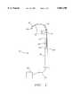
- FIG. 1is a perspective view of the multiple antenna ablation apparatus of the present invention illustrating a primary antenna and a single laterally deployed secondary antenna.
- FIG. 2is a perspective view of a conic geometric ablation achieved with the apparatus of FIG. 1.
- FIG. 3perspective view of the multiple antenna ablation apparatus of the present invention with two secondary antennas.
- FIG. 4is a perspective view illustrating the adjacent positioning of two secondary antennas next to a selected tissue mass.
- FIG. 5is a perspective view illustrating the positioning of the multiple antenna ablation apparatus in the center of a selected tissue mass, and the creation of a cylindrical ablation.
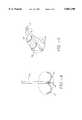
- FIG. 6(a)is a perspective view of the multiple antenna ablation of the present invention illustrating two secondary antennas which provide a retaining and gripping function.
- FIG. 6(b)is a perspective view of the multiple antenna ablation of the present invention illustrating three secondary antennas which provide a retaining and gripping function.
- FIG. 6(c)is a cross-sectional view of the apparatus of FIG. 6(b) taken along the lines 6(c)--6(c).
- FIG. 7is a perspective view of the multiple antenna ablation of the present invention illustrating the deployment of three secondary antennas from a distal end of the insulation sleeve surrounding the primary antenna.
- FIG. 8is perspective view of the multiple antenna ablation of the present invention illustrating the deployment of two secondary antennas from the primary antenna, and the deployment of three secondary antennas from the distal end of the insulation sleeve surrounding the primary antenna.
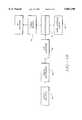
- FIG. 9is a block diagram illustrating the inclusion of a controller, energy source and other electronic components of the present invention.
- FIG. 10is a block diagram illustrating an analog amplifier, analog multiplexer and microprocessor used with the present invention.
- an ablation treatment apparatus 10includes a multiple antenna device 12.
- Multiple antenna device 12includes a primary antenna 14, and one or more secondary antennas 16, which are typically electrodes.
- Secondary antennas 16are initially positioned in a primary antenna lumen when primary antenna 14 is advanced through tissue.
- primary antenna 14reaches a selected tissue ablation site in a selected tissue mass, including but not limited to a solid lesion, secondary antennas 16 are laterally deployed from the primary antenna lumen and into the selected tissue mass.
- Ablationproceeds from the interior of the selected tissue mass in a direction towards a periphery of the selected tissue mass.
- Each primary and secondary antenna 14 and 16has an exterior ablation surface which delivers electromagnetic energy to the selected tissue mass.
- the length and size of each ablation surfacecan be variable.
- the length of primary antenna ablation surface relative to secondary antenna ablation surfacecan be 20% or greater, 33 and 1/3% or greater, 50% or greater, 75% or greater, about the same length, or greater than the length of secondary electrode ablation surface.
- Lengths of primary and secondary antennas 14 and 16can be adjustable.
- Primary antenna 14can be moved up and down, rotated about its longitudinal axis, and moved back and forth, in order to define, along with sensors, the periphery or boundary of the selected tissue mass, including but not limited to a tumor. This provides a variety of different geometries, not always symmetrical, that can be ablated.
- the ablationcan be between the ablation surfaces of primary and secondary antennas 14 and 16 when operated in a monopolar mode with a ground pad.
- Primary antenna 14is constructed so that it can be introduced percutaneously or laparoscopically through tissue without an introducer.
- Primary antenna 14combines the function of an introducer and an electrode.
- Primary antenna 14can have a sharpened distal end 14' to assist introduction through tissue.
- Each secondary antenna 16has a distal end 16' that is constructed to be less structurally rigid than primary antenna 14.
- Distal end 16'is that section of secondary antenna 16 that is advanced from the lumen antenna 14 and into the selected tissue mass. Distal end is typically less structurally rigid that primary antenna 14. However, even though sections of secondary antenna 16 which are not advanced through the selected tissue mass may be less structurally rigid than primary antenna 14.
- Structurally rigidityis determined by, (i) choosing different materials for antenna 14 and and distal end 16' or some greater length of secondary antenna 16, (ii) using the same material but having less of it for secondary antenna 16 or distal end 16', e.g., secondary antenna 16 or distal end 16' is not as thick as primary electrode 14, or (iii) including another material in one of the antennas 14 or 16 to vary their structural rigidity.
- structural rigidityis defined as the amount of deflection that an antenna has relative to its longitudinal axis. It will be appreciated that a given antenna will have different levels of rigidity depending on its length.
- Primary and secondary antennas 14 and 16can be made of a variety of conductive materials, both metallic and non-metallic.
- One suitable materialis type 304 stainless steel of hypodermic quality.
- all or a portion of secondary electrode 16can be made of a shaped memory metal, such as NiTi, commercially available from Raychem Corporation, Menlo Park, Calif.
- Each of primary or secondary antennas 14 or 16can have different lengths.
- the lengthscan be determined by the actual physical length of an antenna, the amount of an antenna that has an ablation delivery surface, and the length of an antenna that is not covered by an insulator. Suitable lengths include but are not limited to 17.5 cm, 25.0 cm. and 30.0 cm.
- the actual length of an antennadepends on the location of the selected tissue mass to be ablated, its distance from the skin, its accessibility as well as whether or not the physician chooses a laproscopic, percutaneous or other procedure.
- ablation treatment apparatus 10, and more particularly multiple antenna device 12can be introduced through a guide to the desired tissue mass site.
- An insulation sleeve 18may be positioned around an exterior of one or both of the primary and secondary antennas 14 and 16 respectively. Preferably, each insulation sleeve 18 is adjustably positioned so that the length of an antenna ablation surface can be varied. Each insulation sleeve 18 surrounding a primary antenna 14 can include one or more apertures. This permits the introduction of a secondary antenna 16 through primary antenna 14 and insulation sleeve 18.
- insulation sleeve 18can comprise a polyamide material.
- a sensor 24may be positioned on top of polyimide insulation sleeve 18.
- the polyamide insulation sleeve 18is semi-rigid. Sensor 24 can lay down substantially along the entire length of polyamide insulation sleeve 18.
- Primary antenna 14is made of a stainless-steel hypodermic tubing with 2 cm of exposed ablation surface.
- Secondary antennas 16have distal ends 16' that are made of NiTi hypodermic tubing.
- a handleis included with markings to show the varying distance of secondary antennas 16 from primary antenna 14. Fluid infusion is delivered through a Luer port at a side of the handle.
- Type-T thermocouplesare positioned at distal ends 16'.
- An energy source 20is connected to multiple antenna device 12 with one or more cables 22.
- Energy source 20can be an RF source, microwave source, short wave source, laser source and the like.
- Multiple antenna device 12can be comprised of primary and secondary antennas 14 and 16 that are RF electrodes, microwave antennas, as well as combinations thereof.
- Energy source 20may be a combination RF/microwave box.
- a laser optical fiber, coupled to a laser source 20can be introduced through one or both of primary or secondary antennas 14 and 16.
- One or more of the primary or secondary antennas 14 and 16can be an arm for the purposes of introducing the optical fiber.
- Antennas 14 and 16may be electromagnetically coupled by wiring, soldering, connection to a common couplet, and the like. This permits only one antenna 14 or 16 to be coupled to energy source 20 and use of a single cable 22.
- One or more sensors 24may be positioned on interior or exterior surfaces of primary antenna 14, secondary antenna 16 or insulation sleeve 18. Preferably sensors 24 are positioned at primary antenna distal end 14', secondary antenna distal end 16' and insulation sleeve distal end 18'. Sensors 24 permit accurate measurement of temperature at a tissue site in order to determine, (i) the extent of ablation, (ii) the amount of ablation, (iii) whether or not further ablation is needed and (iv) the boundary or periphery of the ablated mass. Further, sensors 24 prevent non-targeted tissue from being destroyed or ablated.
- Sensors 24are of conventional design, including but not limited to thermistors, thermocouples, resistive wires, and the like. Suitable thermal sensors 24 include a T type thermocouple with copper constantene, J type, E type, K type, fiber optics, resistive wires, thermocouple IR detectors, and the like. It will be appreciated that sensors 24 need not be thermal sensors.
- Sensors 24measure temperature and/or impedance to permit monitoring and a desired level of ablation to be achieved without destroying too much tissue. This reduces damage to tissue surrounding the targeted mass to be ablated. By monitoring the temperature at various points within the interior of the selected tissue mass, a determination of the selected tissue mass periphery can be made, as well as a determination of when ablation is complete. If at any time sensor 24 determines that a desired ablation temperature is exceeded, then an appropriate feedback signal is received at energy source 20 which then regulates the amount of energy delivered to primary and/or secondary antennas 14 and 16.
- the geometry of the ablated massis selectable and controllable. Any number of different ablation geometries can be achieved. This is a result of having variable lengths for primary antenna 14 and secondary antenna 16 ablation surfaces as well as the inclusion of sensors 24.
- distal end 16'is laterally deployed relative to a longitudinal axis of primary antenna 14 out of an aperture 26 formed in primary antenna 14.
- Aperture 26is at distal end 14' or formed in a side of an exterior of antenna 14.
- a method for creating an ablation volume in a selected tissue massincludes inserting and advancing primary antenna 14 through tissue and into a selected tissue mass. Secondary antennas 16 are positioned in a lumen formed in antenna 14 while antenna 14 is advanced through tissue. At least one distal end 16' is deployed from the primary antenna lumen into the selected tissue mass in a lateral direction relative to the longitudinal axis of primary antenna 14. Electromagnetic energy is delivered from one of a primary antenna ablation surface, a secondary antenna ablation surface or both to the selected tissue mass.
- An ablation volumeis created in the selected tissue mass.
- the ablationis between the ablation surfaces of the antennas.
- secondary antenna 16can be deflected a few degrees from the longitudinal axis of primary antenna 14, or secondary antenna can be deflected in any number of geometric configurations, including but not limited to a "J" hook. Further, secondary antenna 16 is capable of being introduced from primary antenna 14 a few millimeters from primary antenna, or a much larger distance. Ablation by secondary antenna 16 can begin a few millimeters away from primary antenna 14, or secondary electrode 16 can be advanced a greater distance from primary antenna 14 and at that point the initial ablation by secondary antenna 16 begins.
- primary antenna 14has been introduced into a selected tissue mass 28.
- secondary antenna distal end 16'is advanced out of aperture 26 and into selected tissue mass 28.
- Insulation sleeves 18are adjusted for primary and secondary antennas 14 and 16 respectively.
- RF, microwave, short wave and the like energyis delivery to antenna 16 in a monopolar mode (RF), or alternatively, multiple antenna device 12 can be operated in a bipolar mode (RF).
- Multi antenna device 12can be switched between monopolar and bipolar operation and has multiplexing capability between antennas 14 and 16.
- Secondary antenna distal end 16'is retracted back into primary antenna 14, and primary antenna is then rotated. Secondary antenna distal end 16' is then introduced into selected tissue mass 28.
- Secondary antennamay be introduced a short distance into selected tissue mass 28 to ablate a small area. It can then be advanced further into any number of times to create more ablation zones. Again, secondary antenna distal end 16' is retracted back into primary antenna 14, and primary antenna 14 can be, (i) rotated again, (ii) moved along a longitudinal axis of selected tissue mass 28 to begin another series of ablations with secondary antenna distal end 16' being introduced and retracted in and out of primary antenna 14, or (iii) removed from selected tissue mass 28.
- a number of parameterspermit ablation of selected tissue masses 28 of different sign and shapes including a series of ablations having primary and secondary antennas 14 and 16 with variable length ablation surfaces and the use of sensor 24.
- two secondary antennas 16are each deployed out of distal end 14' and introduced into selected tissue mass 28.
- Secondary antennas 16form a plane and the area of ablation extends between the ablation surfaces of primary and secondary antennas 14 and 16.
- Primary antenna 14can be introduced in an adjacent relationship to selected tissue mass 28. This particular deployment is particularly useful for small selected tissue masses 28, or where piercing selected tissue mass 28 is not desirable.
- Primary antenna 14can be rotated, with secondary antennas 16 retracted into a central lumen of primary antenna 14, and another ablation volume defined between the two secondary antennas 16 is created. Further, primary electrode 14 can be withdrawn from its initial position adjacent to selected tissue mass 28, repositioned to another position adjacent to selected tissue mass 28, and secondary antennas 16 deployed to begin another ablation cycle. Any variety of different positionings may be utilized to create a desired ablation geometry for selected tissue mass of different geometries and sizes.
- FIG. 4three secondary antennas 16 arc introduced into selected tissue mass 28.
- the effectis the creation of an ablation volume without leaving non-ablated areas between antenna ablation surfaces. The ablation is complete.
- a center of selected tissue mass 28is pierced by primary antenna 14, secondary antennas 16 are laterally deployed and retracted, primary antenna 14 is rotated, secondary antennas 16 are deployed and retracted, and so on until a cylindrical ablation volume is achieved.
- Multiple antenna device 12can be operated in the bipolar mode between the two secondary antennas 16, or between a secondary antenna 16 and primary antenna 14. Alternatively, multiple antenna device 12 can be operated in a monopolar mode.
- Secondary antennas 16can serve the additional function of anchoring multiple antenna device 12 in a selected mass, as illustrated in FIGS. 6(a) and 6(b).
- FIG. 6(a)one or both secondary antennas 16 are used to anchor and position primary antenna 14. Further, one or both secondary antennas 16 are also used to ablate tissue.
- FIG. 6(b)three secondary antennas are deployed and anchor primary antenna 14.
- FIG. 6(c)illustrates the infusion capability of multiple antenna device 12.
- Three secondary antennas 16are positioned in a central lumen 14" of primary antenna 14.
- One or more of the secondary antennas 16can also include a central lumen coupled to an infusion source.
- Central lumen 14"is coupled to an infusion source and delivers a variety of infusion mediums to selected places both within and outside of the targeted ablation mass.
- Suitable infusion mediumsinclude but are not limited to, therapeutic agents, conductivity enhancement mediums, contrast agents or dyes, and the like.
- An example of a therapeutic agentis a chemotherapeutic agent.
- insulation sleeve 18can include one or more lumens for receiving secondary antennas 16 which are deployed out of an insulation sleeve distal end 18'.
- FIG. 8illustrates two secondary antennas 16 being introduced out of insulation sleeve distal end 18', and two secondary antennas 16 introduced through apertures 26 formed in primary antenna 14. As illustrated, the secondary electrodes introduced through apertures 26 provide an anchoring function. It will be appreciated that FIG. 8 illustrates how secondary antennas 16 can have a variety of different geometric configurations in multiple antenna device 12.
- a feedback control system 29is connected to energy source 20, sensors 24 and antennas 14 and 16.
- Feedback control system 29receives temperature or impedance data from sensors 24 and the amount of electromagnetic energy received by antennas 14 and 16 is modified from an initial setting of ablation energy output, ablation time, temperature, and current density (the "Four Parameters").
- Feedback control system 29can automatically change any of the Four Parameters.
- Feedback control system 29can detect impedance or temperature and change any of the Four Parameters.
- Feedback control systemcan include a multiplexer to multiplex different antennas, a temperature detection circuit that provides a control signal representative of temperature or impedance detected at one or more sensors 24.
- a microprocessorcan be connected to the temperature control circuit.
- a control signalis generated by controller 38 that is proportional to the difference between an actual measured value, and a desired value.
- the control signalis used by power circuits 40 to adjust the power output in an appropriate amount in order to maintain the desired power delivered at the respective primary and/or secondary antennas 14 and 16.
- temperatures detected at sensors 24provide feedback for maintaining a selected power.
- the actual temperaturesare measured at temperature measurement device 42, and the temperatures are displayed at user interface and display 36.
- a control signalis generated by controller 38 that is proportional to the difference between an actual measured temperature, and a desired temperature.
- the control signalis used by power circuits 40 to adjust the power output in an appropriate amount in order to maintain the desired temperature delivered at the respective sensor 24.
- a multiplexercan be included to measure current, voltage and temperature, at the numerous sensors 24, and energy is delivered between primary antenna 14 and secondary antennas 16.
- Controller 38can be a digital or analog controller, or a computer with software.
- controller 38When controller 38 is a computer it can include a CPU coupled through a system bus. On this system can be a keyboard, a disk drive, or other non-volatile memory systems, a display, and other peripherals, as are known in the art. Also coupled to the bus are a program memory and a data memory.
- User interface and display 36includes operator controls and a display.
- Controller 38can be coupled to imaging systems, including but not limited to ultrasound, CT scanners, X-ray, MRI, mammographic X-ray and the like. Further, direct visualization and tactile imaging can be utilized.
- the output of current sensor 30 and voltage sensor 32is used by controller 38 to maintain a selected power level at primary and secondary antennas 14 and 16.
- the amount of RF energy deliveredcontrols the amount of power.
- a profile of power deliveredcan be incorporated in controller 38, and a preset amount of energy to be delivered can also be profiled.
- Circuitry, software and feedback to controller 38result in process control, and the maintenance of the selected power, and are used to change, (i) the selected power, including RF, microwave, laser and the like, (ii) the duty cycle (on-off and wattage), (iii) bipolar or monopolar energy delivery and (iv) infusion medium delivery, including flow rate and pressure.
- process variablesare controlled and varied, while maintaining the desired delivery of power independent of changes in voltage or current, based on temperatures monitored at sensors 24.
- Analog amplifier 44can be a conventional differential amplifier circuit for use with sensors 24.
- the output of analog amplifier 44is sequentially connected by an analog multiplexer 46 to the input of A/D converter 48.
- the output of analog amplifier 44is a voltage which represents the respective sensed temperatures.
- Digitized amplifier output voltagesare supplied by A/D converter 48 to a microprocessor 50.
- Microprocessor 50may be Model No. 68HCII available from Motorola. However, it will be appreciated that any suitable microprocessor or general purpose digital or analog computer can be used to calculate impedance or temperature.
- Microprocessor 50sequentially receives and stores digital representations of impedance and temperature. Each digital value received by microprocessor 50 corresponds to different temperatures and impedances.
- Calculated power and impedance valuescan be indicated on user interface and display 36. Alternatively, or in addition to the numerical indication of power or impedance, calculated impedance and power values can be compared by microprocessor 50 with power and impedance limits. When the values exceed predetermined power or impedance values, a warning can be given on user interface and display 36, and additionally, the delivery of RF energy can be reduced, modified or interrupted. A control signal from microprocessor 50 can modify the power level supplied by energy source 20.
Landscapes
- Health & Medical Sciences (AREA)
- Life Sciences & Earth Sciences (AREA)
- Engineering & Computer Science (AREA)
- Surgery (AREA)
- Biomedical Technology (AREA)
- Nuclear Medicine, Radiotherapy & Molecular Imaging (AREA)
- Animal Behavior & Ethology (AREA)
- General Health & Medical Sciences (AREA)
- Public Health (AREA)
- Veterinary Medicine (AREA)
- Otolaryngology (AREA)
- Physics & Mathematics (AREA)
- Heart & Thoracic Surgery (AREA)
- Medical Informatics (AREA)
- Molecular Biology (AREA)
- Plasma & Fusion (AREA)
- Radiology & Medical Imaging (AREA)
- Electromagnetism (AREA)
- Surgical Instruments (AREA)
Abstract
Description
Claims (43)
Priority Applications (2)
| Application Number | Priority Date | Filing Date | Title |
|---|---|---|---|
| US08/574,618US5863290A (en) | 1995-08-15 | 1995-12-19 | Multiple antenna ablation apparatus and method |
| US08/963,035US5951547A (en) | 1995-08-15 | 1997-11-03 | Multiple antenna ablation apparatus and method |
Applications Claiming Priority (2)
| Application Number | Priority Date | Filing Date | Title |
|---|---|---|---|
| US08/515,379US5683384A (en) | 1993-11-08 | 1995-08-15 | Multiple antenna ablation apparatus |
| US08/574,618US5863290A (en) | 1995-08-15 | 1995-12-19 | Multiple antenna ablation apparatus and method |
Related Parent Applications (2)
| Application Number | Title | Priority Date | Filing Date |
|---|---|---|---|
| US08/515,379Continuation-In-PartUS5683384A (en) | 1993-11-08 | 1995-08-15 | Multiple antenna ablation apparatus |
| US08/515,379ContinuationUS5683384A (en) | 1993-11-08 | 1995-08-15 | Multiple antenna ablation apparatus |
Related Child Applications (1)
| Application Number | Title | Priority Date | Filing Date |
|---|---|---|---|
| US08/963,035Continuation-In-PartUS5951547A (en) | 1995-08-15 | 1997-11-03 | Multiple antenna ablation apparatus and method |
Publications (1)
| Publication Number | Publication Date |
|---|---|
| US5863290Atrue US5863290A (en) | 1999-01-26 |
Family
ID=27058480
Family Applications (1)
| Application Number | Title | Priority Date | Filing Date |
|---|---|---|---|
| US08/574,618Expired - LifetimeUS5863290A (en) | 1995-08-15 | 1995-12-19 | Multiple antenna ablation apparatus and method |
Country Status (1)
| Country | Link |
|---|---|
| US (1) | US5863290A (en) |
Cited By (135)
| Publication number | Priority date | Publication date | Assignee | Title |
|---|---|---|---|---|
| US6014589A (en)* | 1997-11-12 | 2000-01-11 | Vnus Medical Technologies, Inc. | Catheter having expandable electrodes and adjustable stent |
| US6024742A (en)* | 1998-08-22 | 2000-02-15 | Tu; Lily Chen | Ablation apparatus for treating hemorrhoids |
| US6033398A (en)* | 1996-03-05 | 2000-03-07 | Vnus Medical Technologies, Inc. | Method and apparatus for treating venous insufficiency using directionally applied energy |
| US6033397A (en)* | 1996-03-05 | 2000-03-07 | Vnus Medical Technologies, Inc. | Method and apparatus for treating esophageal varices |
| US6036687A (en)* | 1996-03-05 | 2000-03-14 | Vnus Medical Technologies, Inc. | Method and apparatus for treating venous insufficiency |
| US6135997A (en)* | 1996-03-05 | 2000-10-24 | Vnus Medical Technologies, Inc. | Method for treating hemorrhoids |
| US6165172A (en)* | 1997-09-11 | 2000-12-26 | Vnus Medical Technologies, Inc. | Expandable vein ligator catheter and method of use |
| US6179832B1 (en) | 1997-09-11 | 2001-01-30 | Vnus Medical Technologies, Inc. | Expandable catheter having two sets of electrodes |
| US6258084B1 (en) | 1997-09-11 | 2001-07-10 | Vnus Medical Technologies, Inc. | Method for applying energy to biological tissue including the use of tumescent tissue compression |
| US6322559B1 (en) | 1998-07-06 | 2001-11-27 | Vnus Medical Technologies, Inc. | Electrode catheter having coil structure |
| US6347251B1 (en) | 1999-12-23 | 2002-02-12 | Tianquan Deng | Apparatus and method for microwave hyperthermia and acupuncture |
| WO2002022032A1 (en) | 2000-09-15 | 2002-03-21 | Radiotherapeutics Corporation | Methods and systems for focused bipolar tissue ablation |
| US6398780B1 (en) | 1997-09-11 | 2002-06-04 | Vnus Medical Technologies, Inc. | Expandable vein ligator catheter and method of use |
| US6405733B1 (en) | 2000-02-18 | 2002-06-18 | Thomas J. Fogarty | Device for accurately marking tissue |
| US20020087151A1 (en)* | 2000-12-29 | 2002-07-04 | Afx, Inc. | Tissue ablation apparatus with a sliding ablation instrument and method |
| US20020128642A1 (en)* | 1998-10-23 | 2002-09-12 | Afx, Inc. | Directional microwave ablation instrument with marking device |
| US20020138109A1 (en)* | 2001-01-13 | 2002-09-26 | Medtronic, Inc. | Method and system for organ positioning and stabilization |
| US20020193783A1 (en)* | 2000-01-18 | 2002-12-19 | Afx, Inc. | Microwave ablation instrument with flexible antenna assembly and method |
| US6517536B2 (en) | 2000-04-27 | 2003-02-11 | Atricure, Inc. | Transmural ablation device and method |
| US6569162B2 (en) | 2001-03-29 | 2003-05-27 | Ding Sheng He | Passively self-cooled electrode design for ablation catheters |
| US20030163128A1 (en)* | 2000-12-29 | 2003-08-28 | Afx, Inc. | Tissue ablation system with a sliding ablating device and method |
| US20030195499A1 (en)* | 2002-04-16 | 2003-10-16 | Mani Prakash | Microwave antenna having a curved configuration |
| US20030195500A1 (en)* | 1999-06-17 | 2003-10-16 | Moorman Jack W. | Needle kit and method for microwave ablation, track coagulation, and biopsy |
| US6638277B2 (en) | 2000-07-06 | 2003-10-28 | Scimed Life Systems, Inc. | Tumor ablation needle with independently activated and independently traversing tines |
| US6638273B1 (en) | 1996-03-05 | 2003-10-28 | Vnus Medical Technologies, Inc. | Expandable catheter having improved electrode design, and method for applying energy |
| US6682501B1 (en)* | 1996-02-23 | 2004-01-27 | Gyrus Ent, L.L.C. | Submucosal tonsillectomy apparatus and method |
| US20040039429A1 (en)* | 2002-08-21 | 2004-02-26 | Daniel Steven A. | Apparatus and method for tissue resection |
| US6722371B1 (en) | 2000-02-18 | 2004-04-20 | Thomas J. Fogarty | Device for accurately marking tissue |
| US20040077951A1 (en)* | 2002-07-05 | 2004-04-22 | Wei-Chiang Lin | Apparatus and methods of detection of radiation injury using optical spectroscopy |
| US20040106937A1 (en)* | 2002-06-21 | 2004-06-03 | Afx, Inc. | Clamp accessory and method for an ablation instrument |
| US6752154B2 (en) | 2000-02-18 | 2004-06-22 | Thomas J. Fogarty | Device for accurately marking tissue |
| US6752767B2 (en) | 2002-04-16 | 2004-06-22 | Vivant Medical, Inc. | Localization element with energized tip |
| US20040138652A1 (en)* | 2000-04-12 | 2004-07-15 | Afx, Inc. | Electrode arrangement for use in a medical instrument |
| US20040147902A1 (en)* | 2001-02-28 | 2004-07-29 | Mcguckin James F. | Method for delivering ablation fluid to treat lesions |
| US20050004567A1 (en)* | 2002-08-21 | 2005-01-06 | Daniel Steven A. | Thermal coagulation of tissue during tissue resection |
| US20050015081A1 (en)* | 2003-07-18 | 2005-01-20 | Roman Turovskiy | Devices and methods for cooling microwave antennas |
| US20050021024A1 (en)* | 2000-04-27 | 2005-01-27 | Hooven Michael D. | Transmural ablation device with temperature sensor |
| US20050049586A1 (en)* | 2003-07-11 | 2005-03-03 | Daniel Steven A. | Thermal ablation of biological tissue |
| US20050075629A1 (en)* | 2002-02-19 | 2005-04-07 | Afx, Inc. | Apparatus and method for assessing tissue ablation transmurality |
| US20050080409A1 (en)* | 2003-10-10 | 2005-04-14 | Scimed Life Systems, Inc. | Multi-zone bipolar ablation probe assembly |
| US6905498B2 (en) | 2000-04-27 | 2005-06-14 | Atricure Inc. | Transmural ablation device with EKG sensor and pacing electrode |
| US6932811B2 (en) | 2000-04-27 | 2005-08-23 | Atricure, Inc. | Transmural ablation device with integral EKG sensor |
| US20050187545A1 (en)* | 2004-02-20 | 2005-08-25 | Hooven Michael D. | Magnetic catheter ablation device and method |
| US20050190982A1 (en)* | 2003-11-28 | 2005-09-01 | Matsushita Electric Industrial Co., Ltd. | Image reducing device and image reducing method |
| US20050209564A1 (en)* | 2001-01-13 | 2005-09-22 | Medtronic, Inc. | Devices and methods for interstitial injection of biologic agents into tissue |
| US20050234444A1 (en)* | 2004-04-14 | 2005-10-20 | Hooven Michael D | Electrode and bipolar ablation method using same |
| US6989004B2 (en) | 2001-02-28 | 2006-01-24 | Rex Medical, L.P. | Apparatus for delivering ablation fluid to treat lesions |
| US20060041243A1 (en)* | 2001-01-13 | 2006-02-23 | Medtronic, Inc. | Devices and methods for interstitial injection of biologic agents into tissue |
| US20060047278A1 (en)* | 2004-06-02 | 2006-03-02 | Christian Steven C | Ablation device with jaws |
| US20060079888A1 (en)* | 1997-07-18 | 2006-04-13 | Mulier Peter M J | Device and method for ablating tissue |
| US20060089635A1 (en)* | 2004-10-22 | 2006-04-27 | Scimed Life Systems, Inc. | Methods and apparatus for focused bipolar tissue ablation using an insulated shaft |
| US20060173359A1 (en)* | 2002-09-30 | 2006-08-03 | Lin Wei C | Optical apparatus for guided liver tumor treatment and methods |
| US7087040B2 (en) | 2001-02-28 | 2006-08-08 | Rex Medical, L.P. | Apparatus for delivering ablation fluid to treat lesions |
| US7099717B2 (en) | 2002-01-03 | 2006-08-29 | Afx Inc. | Catheter having improved steering |
| US20060206107A1 (en)* | 1999-05-28 | 2006-09-14 | Afx, Inc. | Monopole tip for ablation catheter and methods for using same |
| US20070049863A1 (en)* | 2003-01-14 | 2007-03-01 | Jahns Scott E | Devices and methods for interstitial injection of biologic agents into tissue |
| US7192427B2 (en) | 2002-02-19 | 2007-03-20 | Afx, Inc. | Apparatus and method for assessing transmurality of a tissue ablation |
| US7226446B1 (en)* | 1999-05-04 | 2007-06-05 | Dinesh Mody | Surgical microwave ablation assembly |
| US20070185479A1 (en)* | 2006-02-06 | 2007-08-09 | Liming Lau | Methods and devices for performing ablation and assessing efficacy thereof |
| US20070225697A1 (en)* | 2006-03-23 | 2007-09-27 | Ketan Shroff | Apparatus and methods for cardiac ablation |
| US7288092B2 (en) | 2003-04-23 | 2007-10-30 | Atricure, Inc. | Method and apparatus for ablating cardiac tissue with guide facility |
| US7291161B2 (en) | 2002-10-02 | 2007-11-06 | Atricure, Inc. | Articulated clamping member |
| US7318824B2 (en) | 2001-11-02 | 2008-01-15 | Vivant Medical, Inc. | High-strength microwave antenna assemblies |
| US20080033419A1 (en)* | 2006-08-04 | 2008-02-07 | Nields Morgan W | Method for planning, performing and monitoring thermal ablation |
| US20080033420A1 (en)* | 2006-08-04 | 2008-02-07 | Nields Morgan W | Methods for planning and performing thermal ablation |
| US20080033417A1 (en)* | 2006-08-04 | 2008-02-07 | Nields Morgan W | Apparatus for planning and performing thermal ablation |
| US20080033418A1 (en)* | 2006-08-04 | 2008-02-07 | Nields Morgan W | Methods for monitoring thermal ablation |
| US20080039879A1 (en)* | 2006-08-09 | 2008-02-14 | Chin Albert K | Devices and methods for atrial appendage exclusion |
| US20080071264A1 (en)* | 2006-09-14 | 2008-03-20 | Larry Azure | Ablation probe with deployable electrodes |
| US20080068493A1 (en)* | 2006-09-14 | 2008-03-20 | Hiroaki Hida | Image pickup apparatus with rotary lens barrel |
| US20080082093A1 (en)* | 2006-09-29 | 2008-04-03 | Prakash Mani N | Microwave antenna assembly and method of using the same |
| US20080292255A1 (en)* | 2007-04-27 | 2008-11-27 | Vnus Medical Technologies, Inc. | Systems and methods for treating hollow anatomical structures |
| US20090093809A1 (en)* | 2007-10-05 | 2009-04-09 | Anderson Evan R | Devices and methods for minimally-invasive surgical procedures |
| US20090138005A1 (en)* | 2007-11-27 | 2009-05-28 | Vivant Medical, Inc. | Targeted Cooling of Deployable Microwave Antenna |
| US20090196480A1 (en)* | 2008-02-04 | 2009-08-06 | Alba-Tx, Inc. | Methods And Apparatuses For Planning, Performing, Monitoring And Assessing Thermal Ablation |
| US20090209986A1 (en)* | 2008-02-15 | 2009-08-20 | Stewart Michael C | Devices, Tools and Methods for Atrial Appendage Exclusion |
| US20090292211A1 (en)* | 2002-07-05 | 2009-11-26 | Vanderbilt University | Methods and Apparatus for Optical Spectroscopic Detection of Cell and Tissue Death |
| US20090299443A1 (en)* | 2008-05-30 | 2009-12-03 | Boston Scientific Scimed, Inc. | Guide catheter having vasomodulating electrodes |
| US20090306637A1 (en)* | 2008-06-04 | 2009-12-10 | Vnus Medical Technologies, Inc. | Energy devices and methods for treating hollow anatomical structures |
| US20100174267A1 (en)* | 1998-12-09 | 2010-07-08 | Rex Medical, Lp | Hollow curved superelastic medical needle and method |
| US20100185087A1 (en)* | 2006-08-04 | 2010-07-22 | Nields Morgan W | Methods and apparatuses for performing and monitoring thermal ablation |
| US20100256624A1 (en)* | 2009-04-01 | 2010-10-07 | Vivant Medical, Inc. | Microwave Ablation System with User-Controlled Ablation Size and Method of Use |
| US20100274125A1 (en)* | 2001-04-13 | 2010-10-28 | Novian Health, Inc. | Apparatus and method for delivering ablative laser energy and determining the volume of tumor mass destroyed |
| US20110054458A1 (en)* | 2009-08-25 | 2011-03-03 | Vivan Medical, Inc. | Microwave Ablation with Tissue Temperature Monitoring |
| US20110077638A1 (en)* | 2009-09-29 | 2011-03-31 | Vivant Medical, Inc. | Flow Rate Monitor For Fluid Cooled Microwave Ablation Probe |
| US7967816B2 (en) | 2002-01-25 | 2011-06-28 | Medtronic, Inc. | Fluid-assisted electrosurgical instrument with shapeable electrode |
| US20110202047A1 (en)* | 1997-03-04 | 2011-08-18 | Farley Brian E | Apparatus for Treating Venous Insufficiency Using Directionally Applied Energy |
| US20110208180A1 (en)* | 2010-02-25 | 2011-08-25 | Vivant Medical, Inc. | System and Method for Monitoring Ablation Size |
| US20110213356A1 (en)* | 2009-11-05 | 2011-09-01 | Wright Robert E | Methods and systems for spinal radio frequency neurotomy |
| US20110238057A1 (en)* | 2010-02-16 | 2011-09-29 | Angiodynamics, Inc. | Dual Bracketed Energy Delivery Probe and Method of Use |
| US8298187B2 (en) | 2009-07-07 | 2012-10-30 | Cook Medical Technologies Llc | Fluid injection device |
| US20140296841A1 (en)* | 2010-01-25 | 2014-10-02 | Covidien Lp | System and method for monitoring ablation size |
| US8894641B2 (en) | 2009-10-27 | 2014-11-25 | Covidien Lp | System and method for monitoring ablation size |
| US8926605B2 (en) | 2012-02-07 | 2015-01-06 | Advanced Cardiac Therapeutics, Inc. | Systems and methods for radiometrically measuring temperature during tissue ablation |
| US8954161B2 (en) | 2012-06-01 | 2015-02-10 | Advanced Cardiac Therapeutics, Inc. | Systems and methods for radiometrically measuring temperature and detecting tissue contact prior to and during tissue ablation |
| US8961506B2 (en) | 2012-03-12 | 2015-02-24 | Advanced Cardiac Therapeutics, Inc. | Methods of automatically regulating operation of ablation members based on determined temperatures |
| US9277961B2 (en) | 2009-06-12 | 2016-03-08 | Advanced Cardiac Therapeutics, Inc. | Systems and methods of radiometrically determining a hot-spot temperature of tissue being treated |
| US9510905B2 (en) | 2014-11-19 | 2016-12-06 | Advanced Cardiac Therapeutics, Inc. | Systems and methods for high-resolution mapping of tissue |
| US9517103B2 (en) | 2014-11-19 | 2016-12-13 | Advanced Cardiac Therapeutics, Inc. | Medical instruments with multiple temperature sensors |
| US9616204B2 (en) | 2012-03-02 | 2017-04-11 | Cook Medical Technologies LLC. | Dilation cap for endoluminal device |
| US9636164B2 (en) | 2015-03-25 | 2017-05-02 | Advanced Cardiac Therapeutics, Inc. | Contact sensing systems and methods |
| US9681916B2 (en) | 2012-01-06 | 2017-06-20 | Covidien Lp | System and method for treating tissue using an expandable antenna |
| US9693823B2 (en) | 2012-01-06 | 2017-07-04 | Covidien Lp | System and method for treating tissue using an expandable antenna |
| US9757196B2 (en) | 2011-09-28 | 2017-09-12 | Angiodynamics, Inc. | Multiple treatment zone ablation probe |
| US9764145B2 (en) | 2009-05-28 | 2017-09-19 | Angiodynamics, Inc. | System and method for synchronizing energy delivery to the cardiac rhythm |
| US9839472B2 (en) | 2015-10-29 | 2017-12-12 | Innoblative Designs, Inc. | Screen sphere tissue ablation devices and methods |
| US9855098B2 (en) | 2015-04-29 | 2018-01-02 | Innoblative Designs, Inc. | Cavitary tissue ablation |
| US9855402B2 (en) | 2014-02-15 | 2018-01-02 | Rex Medical, L.P. | Apparatus for delivering fluid to treat renal hypertension |
| US9895189B2 (en) | 2009-06-19 | 2018-02-20 | Angiodynamics, Inc. | Methods of sterilization and treating infection using irreversible electroporation |
| US9949794B2 (en) | 2008-03-27 | 2018-04-24 | Covidien Lp | Microwave ablation devices including expandable antennas and methods of use |
| US9993178B2 (en) | 2016-03-15 | 2018-06-12 | Epix Therapeutics, Inc. | Methods of determining catheter orientation |
| US10070921B2 (en) | 2016-10-17 | 2018-09-11 | Innoblative Designs, Inc. | Treatment devices and methods |
| US10076383B2 (en) | 2012-01-25 | 2018-09-18 | Covidien Lp | Electrosurgical device having a multiplexer |
| US10159526B2 (en) | 2013-02-21 | 2018-12-25 | Stryker Corporation | Tissue ablation cannula assembly |
| US10166062B2 (en) | 2014-11-19 | 2019-01-01 | Epix Therapeutics, Inc. | High-resolution mapping of tissue with pacing |
| US10335224B2 (en) | 2000-08-17 | 2019-07-02 | Angiodynamics, Inc. | Method of destroying tissue cells by electroporation |
| WO2019147619A1 (en)* | 2018-01-23 | 2019-08-01 | Boston Scientific Scimed, Inc. | Enhanced needle array and therapies for tumor ablation |
| US10463426B2 (en) | 2001-08-13 | 2019-11-05 | Angiodynamics, Inc. | Method for treating a tubular anatomical structure |
| US10716618B2 (en) | 2010-05-21 | 2020-07-21 | Stratus Medical, LLC | Systems and methods for tissue ablation |
| US10864039B2 (en) | 2016-02-02 | 2020-12-15 | Innoblative Designs, Inc. | Cavitary tissue ablation system |
| US10869714B2 (en) | 2016-03-01 | 2020-12-22 | Innoblative Designs, Inc. | Resecting and coagulating tissue |
| US10888373B2 (en) | 2017-04-27 | 2021-01-12 | Epix Therapeutics, Inc. | Contact assessment between an ablation catheter and tissue |
| US10912602B2 (en) | 2016-11-08 | 2021-02-09 | Innoblative Designs, Inc. | Electrosurgical tissue and vessel sealing device |
| US11045648B2 (en) | 2017-11-14 | 2021-06-29 | Boston Scientific Scimed, Inc. | Irreversible electroporation through a combination of substance injection and electrical field application |
| US20230165629A1 (en)* | 2021-11-29 | 2023-06-01 | Boston Scientific Scimed, Inc. | Bipolar needle with adjustable electrode for geometrically controlled thermal ablation of biological tissue |
| US11723710B2 (en) | 2016-11-17 | 2023-08-15 | Angiodynamics, Inc. | Techniques for irreversible electroporation using a single-pole tine-style internal device communicating with an external surface electrode |
| US11786297B2 (en) | 2017-07-26 | 2023-10-17 | Innoblative Designs, Inc. | Minimally invasive articulating assembly having ablation capabilities |
| US11931096B2 (en) | 2010-10-13 | 2024-03-19 | Angiodynamics, Inc. | System and method for electrically ablating tissue of a patient |
| US11931094B2 (en) | 2019-10-15 | 2024-03-19 | Boston Scientific Scimed, Inc. | Control system and user interface for an ablation system |
| US11992260B2 (en) | 2020-03-31 | 2024-05-28 | Boston Scientific Scimed, Inc. | Smart probe identification for ablation modalities |
| US12076070B2 (en) | 2019-03-15 | 2024-09-03 | Boston Scientific Scimed, Inc. | Time multiplexed waveform for selective cell ablation |
| US12102376B2 (en) | 2012-02-08 | 2024-10-01 | Angiodynamics, Inc. | System and method for increasing a target zone for electrical ablation |
| US12114911B2 (en) | 2014-08-28 | 2024-10-15 | Angiodynamics, Inc. | System and method for ablating a tissue site by electroporation with real-time pulse monitoring |
| US12201349B2 (en) | 2009-04-03 | 2025-01-21 | Angiodynamics, Inc. | Congestive obstruction pulmonary disease (COPD) |
| US12207863B2 (en) | 2015-10-29 | 2025-01-28 | Innoblative Designs, Inc. | Screen sphere tissue ablation devices and methods |
Citations (116)
| Publication number | Priority date | Publication date | Assignee | Title |
|---|---|---|---|---|
| DE2124684A1 (en) | 1971-05-18 | 1972-11-30 | Stadelmann W | Puncture electrode |
| US3991770A (en)* | 1974-01-24 | 1976-11-16 | Leveen Harry H | Method for treating benign and malignant tumors utilizing radio frequency, electromagnetic radiation |
| US4016886A (en)* | 1974-11-26 | 1977-04-12 | The United States Of America As Represented By The United States Energy Research And Development Administration | Method for localizing heating in tumor tissue |
| US4043342A (en)* | 1974-08-28 | 1977-08-23 | Valleylab, Inc. | Electrosurgical devices having sesquipolar electrode structures incorporated therein |
| US4074718A (en)* | 1976-03-17 | 1978-02-21 | Valleylab, Inc. | Electrosurgical instrument |
| US4080959A (en)* | 1976-06-18 | 1978-03-28 | Leveen Robert F | Method for detection of tumors of the breast |
| US4095602A (en)* | 1976-09-27 | 1978-06-20 | Leveen Harry H | Multi-portal radiofrequency generator |
| US4119102A (en)* | 1975-07-11 | 1978-10-10 | Leveen Harry H | Radio frequency treatment of tumors while inducing hypotension |
| US4140130A (en)* | 1977-05-31 | 1979-02-20 | Storm Iii Frederick K | Electrode structure for radio frequency localized heating of tumor bearing tissue |
| US4154246A (en)* | 1977-07-25 | 1979-05-15 | Leveen Harry H | Field intensification in radio frequency thermotherapy |
| US4230129A (en)* | 1975-07-11 | 1980-10-28 | Leveen Harry H | Radio frequency, electromagnetic radiation device having orbital mount |
| US4285346A (en)* | 1979-03-14 | 1981-08-25 | Harry V. LeVeen | Electrode system |
| US4290435A (en)* | 1979-09-07 | 1981-09-22 | Thermatime A.G. | Internally cooled electrode for hyperthermal treatment and method of use |
| US4303636A (en)* | 1974-08-20 | 1981-12-01 | Gordon Robert T | Cancer treatment |
| US4346715A (en)* | 1978-07-12 | 1982-08-31 | The United States Of America As Represented By The Administrator Of The National Aeronautics And Space Administration | Hyperthermia heating apparatus |
| US4375220A (en)* | 1980-05-09 | 1983-03-01 | Matvias Fredrick M | Microwave applicator with cooling mechanism for intracavitary treatment of cancer |
| US4545368A (en)* | 1983-04-13 | 1985-10-08 | Rand Robert W | Induction heating method for use in causing necrosis of neoplasm |
| US4565200A (en)* | 1980-09-24 | 1986-01-21 | Cosman Eric R | Universal lesion and recording electrode system |
| US4574782A (en)* | 1981-11-16 | 1986-03-11 | Corning Glass Works | Radio frequency-induced hyperthermia for tumor therapy |
| US4586490A (en)* | 1984-02-27 | 1986-05-06 | Katz Harry R | Needle inserting instrument means for interstitial radiotherapy |
| US4676258A (en)* | 1983-01-24 | 1987-06-30 | Kureha Kagaku Kogyo Kabushiki Kaisha | Device for hyperthermia |
| US4709701A (en)* | 1986-04-15 | 1987-12-01 | Medical Research & Development Associates | Apparatus for medical treatment by hyperthermia |
| US4763671A (en)* | 1983-12-27 | 1988-08-16 | Stanford University | Method of treating tumors using selective application of heat and radiation |
| US4800899A (en)* | 1984-10-22 | 1989-01-31 | Microthermia Technology, Inc. | Apparatus for destroying cells in tumors and the like |
| US4813429A (en)* | 1986-05-12 | 1989-03-21 | Biodan Medical Systems Ltd. | Catheter and probe |
| US4823791A (en)* | 1987-05-08 | 1989-04-25 | Circon Acmi Division Of Circon Corporation | Electrosurgical probe apparatus |
| US4860744A (en)* | 1987-11-02 | 1989-08-29 | Raj K. Anand | Thermoelectrically controlled heat medical catheter |
| US4881543A (en)* | 1988-06-28 | 1989-11-21 | Massachusetts Institute Of Technology | Combined microwave heating and surface cooling of the cornea |
| US4887614A (en)* | 1983-09-05 | 1989-12-19 | Kureha Kagaku Kogyo Kabushiki Kaisha | Medical electrode device |
| US4920978A (en)* | 1988-08-31 | 1990-05-01 | Triangle Research And Development Corporation | Method and apparatus for the endoscopic treatment of deep tumors using RF hyperthermia |
| US4931047A (en)* | 1987-09-30 | 1990-06-05 | Cavitron, Inc. | Method and apparatus for providing enhanced tissue fragmentation and/or hemostasis |
| US4945912A (en)* | 1988-11-25 | 1990-08-07 | Sensor Electronics, Inc. | Catheter with radiofrequency heating applicator |
| US4947842A (en)* | 1988-09-22 | 1990-08-14 | Medical Engineering And Development Institute, Inc. | Method and apparatus for treating tissue with first and second modalities |
| US4962761A (en)* | 1987-02-24 | 1990-10-16 | Golden Theodore A | Thermal bandage |
| US4976711A (en)* | 1989-04-13 | 1990-12-11 | Everest Medical Corporation | Ablation catheter with selectively deployable electrodes |
| US4976680A (en)* | 1988-10-07 | 1990-12-11 | Hayman Michael H | Apparatus for in situ radiotherapy |
| US4983159A (en)* | 1985-03-25 | 1991-01-08 | Rand Robert W | Inductive heating process for use in causing necrosis of neoplasms at selective frequencies |
| US5003991A (en)* | 1987-03-31 | 1991-04-02 | Olympus Optical Co., Ltd. | Hyperthermia apparatus |
| US5007908A (en)* | 1989-09-29 | 1991-04-16 | Everest Medical Corporation | Electrosurgical instrument having needle cutting electrode and spot-coag electrode |
| US5009656A (en)* | 1989-08-17 | 1991-04-23 | Mentor O&O Inc. | Bipolar electrosurgical instrument |
| US5010897A (en)* | 1989-04-26 | 1991-04-30 | Leveen Harry H | Apparatus for deep heating of cancer |
| US5047027A (en)* | 1990-04-20 | 1991-09-10 | Everest Medical Corporation | Tumor resector |
| US5057107A (en)* | 1989-04-13 | 1991-10-15 | Everest Medical Corporation | Ablation catheter with selectively deployable electrodes |
| US5067952A (en)* | 1990-04-02 | 1991-11-26 | Gudov Vasily F | Method and apparatus for treating malignant tumors by local hyperpyrexia |
| US5071419A (en)* | 1990-04-30 | 1991-12-10 | Everest Medical Corporation | Percutaneous laparoscopic cholecystectomy instrument |
| US5078717A (en)* | 1989-04-13 | 1992-01-07 | Everest Medical Corporation | Ablation catheter with selectively deployable electrodes |
| US5085649A (en)* | 1990-11-21 | 1992-02-04 | Flynn Vincent J | Torque controlled tubing |
| US5099756A (en)* | 1989-06-01 | 1992-03-31 | Harry H. Leveen | Radio frequency thermotherapy |
| US5100423A (en)* | 1990-08-21 | 1992-03-31 | Medical Engineering & Development Institute, Inc. | Ablation catheter |
| US5122137A (en)* | 1990-04-27 | 1992-06-16 | Boston Scientific Corporation | Temperature controlled rf coagulation |
| US5125928A (en)* | 1989-04-13 | 1992-06-30 | Everest Medical Corporation | Ablation catheter with selectively deployable electrodes |
| US5190517A (en)* | 1991-06-06 | 1993-03-02 | Valleylab Inc. | Electrosurgical and ultrasonic surgical system |
| US5190541A (en)* | 1990-10-17 | 1993-03-02 | Boston Scientific Corporation | Surgical instrument and method |
| US5197964A (en)* | 1991-11-12 | 1993-03-30 | Everest Medical Corporation | Bipolar instrument utilizing one stationary electrode and one movable electrode |
| US5197466A (en)* | 1983-01-21 | 1993-03-30 | Med Institute Inc. | Method and apparatus for volumetric interstitial conductive hyperthermia |
| US5197963A (en)* | 1991-12-02 | 1993-03-30 | Everest Medical Corporation | Electrosurgical instrument with extendable sheath for irrigation and aspiration |
| US5203782A (en)* | 1990-04-02 | 1993-04-20 | Gudov Vasily F | Method and apparatus for treating malignant tumors by local hyperpyrexia |
| US5217458A (en)* | 1992-04-09 | 1993-06-08 | Everest Medical Corporation | Bipolar biopsy device utilizing a rotatable, single-hinged moving element |
| US5236410A (en)* | 1990-08-02 | 1993-08-17 | Ferrotherm International, Inc. | Tumor treatment method |
| US5257451A (en)* | 1991-11-08 | 1993-11-02 | Ep Technologies, Inc. | Method of making durable sleeve for enclosing a bendable electrode tip assembly |
| US5273535A (en)* | 1991-11-08 | 1993-12-28 | Ep Technologies, Inc. | Catheter with electrode tip having asymmetric left and right curve configurations |
| US5275162A (en)* | 1991-11-08 | 1994-01-04 | Ep Technologies, Inc. | Valve mapping catheter |
| US5277696A (en)* | 1991-11-19 | 1994-01-11 | Delma Elektro- Und Medizinische Apparatebau Gesellschaft Mbh | Medical high frequency coagulation instrument |
| US5281218A (en)* | 1992-06-05 | 1994-01-25 | Cardiac Pathways Corporation | Catheter having needle electrode for radiofrequency ablation |
| US5281217A (en)* | 1992-04-13 | 1994-01-25 | Ep Technologies, Inc. | Steerable antenna systems for cardiac ablation that minimize tissue damage and blood coagulation due to conductive heating patterns |
| US5282797A (en)* | 1989-05-30 | 1994-02-01 | Cyrus Chess | Method for treating cutaneous vascular lesions |
| US5293869A (en)* | 1992-09-25 | 1994-03-15 | Ep Technologies, Inc. | Cardiac probe with dynamic support for maintaining constant surface contact during heart systole and diastole |
| US5295955A (en)* | 1992-02-14 | 1994-03-22 | Amt, Inc. | Method and apparatus for microwave aided liposuction |
| US5309910A (en)* | 1992-09-25 | 1994-05-10 | Ep Technologies, Inc. | Cardiac mapping and ablation systems |
| US5314466A (en)* | 1992-04-13 | 1994-05-24 | Ep Technologies, Inc. | Articulated unidirectional microwave antenna systems for cardiac ablation |
| US5313943A (en)* | 1992-09-25 | 1994-05-24 | Ep Technologies, Inc. | Catheters and methods for performing cardiac diagnosis and treatment |
| US5328467A (en)* | 1991-11-08 | 1994-07-12 | Ep Technologies, Inc. | Catheter having a torque transmitting sleeve |
| US5334193A (en)* | 1992-11-13 | 1994-08-02 | American Cardiac Ablation Co., Inc. | Fluid cooled ablation catheter |
| US5342357A (en)* | 1992-11-13 | 1994-08-30 | American Cardiac Ablation Co., Inc. | Fluid cooled electrosurgical cauterization system |
| US5348554A (en)* | 1992-12-01 | 1994-09-20 | Cardiac Pathways Corporation | Catheter for RF ablation with cooled electrode |
| US5363861A (en)* | 1991-11-08 | 1994-11-15 | Ep Technologies, Inc. | Electrode tip assembly with variable resistance to bending |
| US5366490A (en)* | 1992-08-12 | 1994-11-22 | Vidamed, Inc. | Medical probe device and method |
| US5368592A (en)* | 1992-04-13 | 1994-11-29 | Ep Technologies, Inc. | Articulated systems for cardiac ablation |
| US5370678A (en)* | 1992-04-13 | 1994-12-06 | Ep Technologies, Inc. | Steerable microwave antenna systems for cardiac ablation that minimize tissue damage and blood coagulation due to conductive heating patterns |
| US5383917A (en)* | 1991-07-05 | 1995-01-24 | Jawahar M. Desai | Device and method for multi-phase radio-frequency ablation |
| US5385544A (en)* | 1992-08-12 | 1995-01-31 | Vidamed, Inc. | BPH ablation method and apparatus |
| US5398683A (en)* | 1991-05-24 | 1995-03-21 | Ep Technologies, Inc. | Combination monophasic action potential/ablation catheter and high-performance filter system |
| US5409453A (en)* | 1992-08-12 | 1995-04-25 | Vidamed, Inc. | Steerable medical probe with stylets |
| US5421819A (en)* | 1992-08-12 | 1995-06-06 | Vidamed, Inc. | Medical probe device |
| US5423708A (en)* | 1994-08-15 | 1995-06-13 | Allen; Roger D. | Multi-legged, walking toy robot |
| US5423807A (en)* | 1992-04-16 | 1995-06-13 | Implemed, Inc. | Cryogenic mapping and ablation catheter |
| US5433708A (en)* | 1991-05-17 | 1995-07-18 | Innerdyne, Inc. | Method and device for thermal ablation having improved heat transfer |
| US5435805A (en)* | 1992-08-12 | 1995-07-25 | Vidamed, Inc. | Medical probe device with optical viewing capability |
| US5456682A (en)* | 1991-11-08 | 1995-10-10 | Ep Technologies, Inc. | Electrode and associated systems using thermally insulated temperature sensing elements |
| US5456662A (en)* | 1993-02-02 | 1995-10-10 | Edwards; Stuart D. | Method for reducing snoring by RF ablation of the uvula |
| US5458597A (en)* | 1993-11-08 | 1995-10-17 | Zomed International | Device for treating cancer and non-malignant tumors and methods |
| US5458596A (en)* | 1994-05-06 | 1995-10-17 | Dorsal Orthopedic Corporation | Method and apparatus for controlled contraction of soft tissue |
| US5462521A (en)* | 1993-12-21 | 1995-10-31 | Angeion Corporation | Fluid cooled and perfused tip for a catheter |
| US5470308A (en)* | 1992-08-12 | 1995-11-28 | Vidamed, Inc. | Medical probe with biopsy stylet |
| US5472441A (en) | 1993-11-08 | 1995-12-05 | Zomed International | Device for treating cancer and non-malignant tumors and methods |
| US5471982A (en) | 1992-09-29 | 1995-12-05 | Ep Technologies, Inc. | Cardiac mapping and ablation systems |
| US5484400A (en) | 1992-08-12 | 1996-01-16 | Vidamed, Inc. | Dual channel RF delivery system |
| US5486161A (en) | 1993-02-02 | 1996-01-23 | Zomed International | Medical probe device and method |
| US5505730A (en) | 1994-06-24 | 1996-04-09 | Stuart D. Edwards | Thin layer ablation apparatus |
| US5507743A (en) | 1993-11-08 | 1996-04-16 | Zomed International | Coiled RF electrode treatment apparatus |
| US5514131A (en) | 1992-08-12 | 1996-05-07 | Stuart D. Edwards | Method for the ablation treatment of the uvula |
| US5514130A (en) | 1994-10-11 | 1996-05-07 | Dorsal Med International | RF apparatus for controlled depth ablation of soft tissue |
| US5536267A (en) | 1993-11-08 | 1996-07-16 | Zomed International | Multiple electrode ablation apparatus |
| US5542915A (en) | 1992-08-12 | 1996-08-06 | Vidamed, Inc. | Thermal mapping catheter with ultrasound probe |
| US5542916A (en) | 1992-08-12 | 1996-08-06 | Vidamed, Inc. | Dual-channel RF power delivery system |
| US5542928A (en) | 1991-05-17 | 1996-08-06 | Innerdyne, Inc. | Method and device for thermal ablation having improved heat transfer |
| US5545171A (en) | 1994-09-22 | 1996-08-13 | Vidamed, Inc. | Anastomosis catheter |
| US5546267A (en) | 1994-12-08 | 1996-08-13 | Illinois Tool Works Inc. | Communication circuit protector |
| US5545161A (en) | 1992-12-01 | 1996-08-13 | Cardiac Pathways Corporation | Catheter for RF ablation having cooled electrode with electrically insulated sleeve |
| US5545193A (en) | 1993-10-15 | 1996-08-13 | Ep Technologies, Inc. | Helically wound radio-frequency emitting electrodes for creating lesions in body tissue |
| US5549108A (en) | 1992-09-25 | 1996-08-27 | Ep Technologies, Inc. | Cardiac mapping and ablation systems |
| US5549644A (en) | 1992-08-12 | 1996-08-27 | Vidamed, Inc. | Transurethral needle ablation device with cystoscope and method for treatment of the prostate |
| US5556377A (en) | 1992-08-12 | 1996-09-17 | Vidamed, Inc. | Medical probe apparatus with laser and/or microwave monolithic integrated circuit probe |
| US5558673A (en) | 1994-09-30 | 1996-09-24 | Vidamed, Inc. | Medical probe device and method having a flexible resilient tape stylet |
| US5560358A (en) | 1994-09-08 | 1996-10-01 | Radionics, Inc. | Connector design for multi-contact medical electrode |
| US5562703A (en) | 1994-06-14 | 1996-10-08 | Desai; Ashvin H. | Endoscopic surgical instrument |
- 1995
- 1995-12-19USUS08/574,618patent/US5863290A/ennot_activeExpired - Lifetime
Patent Citations (131)
| Publication number | Priority date | Publication date | Assignee | Title |
|---|---|---|---|---|
| DE2124684A1 (en) | 1971-05-18 | 1972-11-30 | Stadelmann W | Puncture electrode |
| US3991770A (en)* | 1974-01-24 | 1976-11-16 | Leveen Harry H | Method for treating benign and malignant tumors utilizing radio frequency, electromagnetic radiation |
| US4303636A (en)* | 1974-08-20 | 1981-12-01 | Gordon Robert T | Cancer treatment |
| US4043342A (en)* | 1974-08-28 | 1977-08-23 | Valleylab, Inc. | Electrosurgical devices having sesquipolar electrode structures incorporated therein |
| US4016886A (en)* | 1974-11-26 | 1977-04-12 | The United States Of America As Represented By The United States Energy Research And Development Administration | Method for localizing heating in tumor tissue |
| US4119102A (en)* | 1975-07-11 | 1978-10-10 | Leveen Harry H | Radio frequency treatment of tumors while inducing hypotension |
| US4230129A (en)* | 1975-07-11 | 1980-10-28 | Leveen Harry H | Radio frequency, electromagnetic radiation device having orbital mount |
| USRE32066E (en)* | 1975-07-11 | 1986-01-21 | Method for treating benign and malignant tumors utilizing radio frequency, electromagnetic radiation | |
| USRE32057E (en)* | 1975-07-11 | 1985-12-31 | Radio frequency treatment of tumors while inducing hypotension | |
| US4074718A (en)* | 1976-03-17 | 1978-02-21 | Valleylab, Inc. | Electrosurgical instrument |
| US4080959A (en)* | 1976-06-18 | 1978-03-28 | Leveen Robert F | Method for detection of tumors of the breast |
| US4095602A (en)* | 1976-09-27 | 1978-06-20 | Leveen Harry H | Multi-portal radiofrequency generator |
| US4140130A (en)* | 1977-05-31 | 1979-02-20 | Storm Iii Frederick K | Electrode structure for radio frequency localized heating of tumor bearing tissue |
| US4154246A (en)* | 1977-07-25 | 1979-05-15 | Leveen Harry H | Field intensification in radio frequency thermotherapy |
| US4346715A (en)* | 1978-07-12 | 1982-08-31 | The United States Of America As Represented By The Administrator Of The National Aeronautics And Space Administration | Hyperthermia heating apparatus |
| US4285346A (en)* | 1979-03-14 | 1981-08-25 | Harry V. LeVeen | Electrode system |
| US4290435A (en)* | 1979-09-07 | 1981-09-22 | Thermatime A.G. | Internally cooled electrode for hyperthermal treatment and method of use |
| US4375220A (en)* | 1980-05-09 | 1983-03-01 | Matvias Fredrick M | Microwave applicator with cooling mechanism for intracavitary treatment of cancer |
| US4565200A (en)* | 1980-09-24 | 1986-01-21 | Cosman Eric R | Universal lesion and recording electrode system |
| US4574782A (en)* | 1981-11-16 | 1986-03-11 | Corning Glass Works | Radio frequency-induced hyperthermia for tumor therapy |
| US5197466A (en)* | 1983-01-21 | 1993-03-30 | Med Institute Inc. | Method and apparatus for volumetric interstitial conductive hyperthermia |
| US4676258A (en)* | 1983-01-24 | 1987-06-30 | Kureha Kagaku Kogyo Kabushiki Kaisha | Device for hyperthermia |
| US4545368A (en)* | 1983-04-13 | 1985-10-08 | Rand Robert W | Induction heating method for use in causing necrosis of neoplasm |
| US4887614A (en)* | 1983-09-05 | 1989-12-19 | Kureha Kagaku Kogyo Kabushiki Kaisha | Medical electrode device |
| US4763671A (en)* | 1983-12-27 | 1988-08-16 | Stanford University | Method of treating tumors using selective application of heat and radiation |
| US4586490A (en)* | 1984-02-27 | 1986-05-06 | Katz Harry R | Needle inserting instrument means for interstitial radiotherapy |
| US4800899A (en)* | 1984-10-22 | 1989-01-31 | Microthermia Technology, Inc. | Apparatus for destroying cells in tumors and the like |
| US4983159A (en)* | 1985-03-25 | 1991-01-08 | Rand Robert W | Inductive heating process for use in causing necrosis of neoplasms at selective frequencies |
| US4709701A (en)* | 1986-04-15 | 1987-12-01 | Medical Research & Development Associates | Apparatus for medical treatment by hyperthermia |
| US4813429A (en)* | 1986-05-12 | 1989-03-21 | Biodan Medical Systems Ltd. | Catheter and probe |
| US4962761A (en)* | 1987-02-24 | 1990-10-16 | Golden Theodore A | Thermal bandage |
| US5003991A (en)* | 1987-03-31 | 1991-04-02 | Olympus Optical Co., Ltd. | Hyperthermia apparatus |
| US4823791A (en)* | 1987-05-08 | 1989-04-25 | Circon Acmi Division Of Circon Corporation | Electrosurgical probe apparatus |
| US4931047A (en)* | 1987-09-30 | 1990-06-05 | Cavitron, Inc. | Method and apparatus for providing enhanced tissue fragmentation and/or hemostasis |
| US4860744A (en)* | 1987-11-02 | 1989-08-29 | Raj K. Anand | Thermoelectrically controlled heat medical catheter |
| US4881543A (en)* | 1988-06-28 | 1989-11-21 | Massachusetts Institute Of Technology | Combined microwave heating and surface cooling of the cornea |
| US4920978A (en)* | 1988-08-31 | 1990-05-01 | Triangle Research And Development Corporation | Method and apparatus for the endoscopic treatment of deep tumors using RF hyperthermia |
| US4947842A (en)* | 1988-09-22 | 1990-08-14 | Medical Engineering And Development Institute, Inc. | Method and apparatus for treating tissue with first and second modalities |
| US4976680A (en)* | 1988-10-07 | 1990-12-11 | Hayman Michael H | Apparatus for in situ radiotherapy |
| US4945912A (en)* | 1988-11-25 | 1990-08-07 | Sensor Electronics, Inc. | Catheter with radiofrequency heating applicator |
| US5246438A (en)* | 1988-11-25 | 1993-09-21 | Sensor Electronics, Inc. | Method of radiofrequency ablation |
| US5125928A (en)* | 1989-04-13 | 1992-06-30 | Everest Medical Corporation | Ablation catheter with selectively deployable electrodes |
| US4976711A (en)* | 1989-04-13 | 1990-12-11 | Everest Medical Corporation | Ablation catheter with selectively deployable electrodes |
| US5057107A (en)* | 1989-04-13 | 1991-10-15 | Everest Medical Corporation | Ablation catheter with selectively deployable electrodes |
| US5078717A (en)* | 1989-04-13 | 1992-01-07 | Everest Medical Corporation | Ablation catheter with selectively deployable electrodes |
| US5010897A (en)* | 1989-04-26 | 1991-04-30 | Leveen Harry H | Apparatus for deep heating of cancer |
| US5282797A (en)* | 1989-05-30 | 1994-02-01 | Cyrus Chess | Method for treating cutaneous vascular lesions |
| US5099756A (en)* | 1989-06-01 | 1992-03-31 | Harry H. Leveen | Radio frequency thermotherapy |
| US5009656A (en)* | 1989-08-17 | 1991-04-23 | Mentor O&O Inc. | Bipolar electrosurgical instrument |
| US5007908A (en)* | 1989-09-29 | 1991-04-16 | Everest Medical Corporation | Electrosurgical instrument having needle cutting electrode and spot-coag electrode |
| US5067952A (en)* | 1990-04-02 | 1991-11-26 | Gudov Vasily F | Method and apparatus for treating malignant tumors by local hyperpyrexia |
| US5203782A (en)* | 1990-04-02 | 1993-04-20 | Gudov Vasily F | Method and apparatus for treating malignant tumors by local hyperpyrexia |
| US5047027A (en)* | 1990-04-20 | 1991-09-10 | Everest Medical Corporation | Tumor resector |
| US5122137A (en)* | 1990-04-27 | 1992-06-16 | Boston Scientific Corporation | Temperature controlled rf coagulation |
| US5071419A (en)* | 1990-04-30 | 1991-12-10 | Everest Medical Corporation | Percutaneous laparoscopic cholecystectomy instrument |
| US5236410A (en)* | 1990-08-02 | 1993-08-17 | Ferrotherm International, Inc. | Tumor treatment method |
| US5100423A (en)* | 1990-08-21 | 1992-03-31 | Medical Engineering & Development Institute, Inc. | Ablation catheter |
| US5190541A (en)* | 1990-10-17 | 1993-03-02 | Boston Scientific Corporation | Surgical instrument and method |
| US5085649A (en)* | 1990-11-21 | 1992-02-04 | Flynn Vincent J | Torque controlled tubing |
| US5542928A (en) | 1991-05-17 | 1996-08-06 | Innerdyne, Inc. | Method and device for thermal ablation having improved heat transfer |
| US5433708A (en)* | 1991-05-17 | 1995-07-18 | Innerdyne, Inc. | Method and device for thermal ablation having improved heat transfer |
| US5398683A (en)* | 1991-05-24 | 1995-03-21 | Ep Technologies, Inc. | Combination monophasic action potential/ablation catheter and high-performance filter system |
| US5190517A (en)* | 1991-06-06 | 1993-03-02 | Valleylab Inc. | Electrosurgical and ultrasonic surgical system |
| US5383917A (en)* | 1991-07-05 | 1995-01-24 | Jawahar M. Desai | Device and method for multi-phase radio-frequency ablation |
| US5275162A (en)* | 1991-11-08 | 1994-01-04 | Ep Technologies, Inc. | Valve mapping catheter |
| US5257451A (en)* | 1991-11-08 | 1993-11-02 | Ep Technologies, Inc. | Method of making durable sleeve for enclosing a bendable electrode tip assembly |
| US5363861A (en)* | 1991-11-08 | 1994-11-15 | Ep Technologies, Inc. | Electrode tip assembly with variable resistance to bending |
| US5273535A (en)* | 1991-11-08 | 1993-12-28 | Ep Technologies, Inc. | Catheter with electrode tip having asymmetric left and right curve configurations |
| US5456682A (en)* | 1991-11-08 | 1995-10-10 | Ep Technologies, Inc. | Electrode and associated systems using thermally insulated temperature sensing elements |
| US5328467A (en)* | 1991-11-08 | 1994-07-12 | Ep Technologies, Inc. | Catheter having a torque transmitting sleeve |
| US5290286A (en)* | 1991-11-12 | 1994-03-01 | Everest Medical Corporation | Bipolar instrument utilizing one stationary electrode and one movable electrode |
| US5197964A (en)* | 1991-11-12 | 1993-03-30 | Everest Medical Corporation | Bipolar instrument utilizing one stationary electrode and one movable electrode |
| US5277696A (en)* | 1991-11-19 | 1994-01-11 | Delma Elektro- Und Medizinische Apparatebau Gesellschaft Mbh | Medical high frequency coagulation instrument |
| US5197963A (en)* | 1991-12-02 | 1993-03-30 | Everest Medical Corporation | Electrosurgical instrument with extendable sheath for irrigation and aspiration |
| US5295955A (en)* | 1992-02-14 | 1994-03-22 | Amt, Inc. | Method and apparatus for microwave aided liposuction |
| US5217458A (en)* | 1992-04-09 | 1993-06-08 | Everest Medical Corporation | Bipolar biopsy device utilizing a rotatable, single-hinged moving element |
| US5314466A (en)* | 1992-04-13 | 1994-05-24 | Ep Technologies, Inc. | Articulated unidirectional microwave antenna systems for cardiac ablation |
| US5370678A (en)* | 1992-04-13 | 1994-12-06 | Ep Technologies, Inc. | Steerable microwave antenna systems for cardiac ablation that minimize tissue damage and blood coagulation due to conductive heating patterns |
| US5281217A (en)* | 1992-04-13 | 1994-01-25 | Ep Technologies, Inc. | Steerable antenna systems for cardiac ablation that minimize tissue damage and blood coagulation due to conductive heating patterns |
| US5368592A (en)* | 1992-04-13 | 1994-11-29 | Ep Technologies, Inc. | Articulated systems for cardiac ablation |
| US5423807A (en)* | 1992-04-16 | 1995-06-13 | Implemed, Inc. | Cryogenic mapping and ablation catheter |
| US5281218A (en)* | 1992-06-05 | 1994-01-25 | Cardiac Pathways Corporation | Catheter having needle electrode for radiofrequency ablation |
| US5536240A (en) | 1992-08-12 | 1996-07-16 | Vidamed, Inc. | Medical probe device and method |
| US5531677A (en) | 1992-08-12 | 1996-07-02 | Vidamed, Inc. | Steerable medical probe with stylets |
| US5366490A (en)* | 1992-08-12 | 1994-11-22 | Vidamed, Inc. | Medical probe device and method |
| US5385544A (en)* | 1992-08-12 | 1995-01-31 | Vidamed, Inc. | BPH ablation method and apparatus |
| US5540655A (en) | 1992-08-12 | 1996-07-30 | Vidamed, Inc. | PBH ablation method and apparatus |
| US5409453A (en)* | 1992-08-12 | 1995-04-25 | Vidamed, Inc. | Steerable medical probe with stylets |
| US5421819A (en)* | 1992-08-12 | 1995-06-06 | Vidamed, Inc. | Medical probe device |
| US5556377A (en) | 1992-08-12 | 1996-09-17 | Vidamed, Inc. | Medical probe apparatus with laser and/or microwave monolithic integrated circuit probe |
| US5542916A (en) | 1992-08-12 | 1996-08-06 | Vidamed, Inc. | Dual-channel RF power delivery system |
| US5470308A (en)* | 1992-08-12 | 1995-11-28 | Vidamed, Inc. | Medical probe with biopsy stylet |
| US5531676A (en) | 1992-08-12 | 1996-07-02 | Vidamed, Inc. | Medical probe device and method |
| US5435805A (en)* | 1992-08-12 | 1995-07-25 | Vidamed, Inc. | Medical probe device with optical viewing capability |
| US5514131A (en) | 1992-08-12 | 1996-05-07 | Stuart D. Edwards | Method for the ablation treatment of the uvula |
| US5370675A (en)* | 1992-08-12 | 1994-12-06 | Vidamed, Inc. | Medical probe device and method |
| US5484400A (en) | 1992-08-12 | 1996-01-16 | Vidamed, Inc. | Dual channel RF delivery system |
| US5554110A (en) | 1992-08-12 | 1996-09-10 | Vidamed, Inc. | Medical ablation apparatus |
| US5549644A (en) | 1992-08-12 | 1996-08-27 | Vidamed, Inc. | Transurethral needle ablation device with cystoscope and method for treatment of the prostate |
| US5542915A (en) | 1992-08-12 | 1996-08-06 | Vidamed, Inc. | Thermal mapping catheter with ultrasound probe |
| US5470309A (en) | 1992-08-12 | 1995-11-28 | Vidamed, Inc. | Medical ablation apparatus utilizing a heated stylet |
| US5549108A (en) | 1992-09-25 | 1996-08-27 | Ep Technologies, Inc. | Cardiac mapping and ablation systems |
| US5313943A (en)* | 1992-09-25 | 1994-05-24 | Ep Technologies, Inc. | Catheters and methods for performing cardiac diagnosis and treatment |
| US5309910A (en)* | 1992-09-25 | 1994-05-10 | Ep Technologies, Inc. | Cardiac mapping and ablation systems |
| US5293869A (en)* | 1992-09-25 | 1994-03-15 | Ep Technologies, Inc. | Cardiac probe with dynamic support for maintaining constant surface contact during heart systole and diastole |
| US5509419A (en) | 1992-09-25 | 1996-04-23 | Ep Technologies, Inc. | Cardiac mapping and ablation systems |
| US5471982A (en) | 1992-09-29 | 1995-12-05 | Ep Technologies, Inc. | Cardiac mapping and ablation systems |
| US5334193A (en)* | 1992-11-13 | 1994-08-02 | American Cardiac Ablation Co., Inc. | Fluid cooled ablation catheter |
| US5437662A (en)* | 1992-11-13 | 1995-08-01 | American Cardiac Ablation Co., Inc. | Fluid cooled electrosurgical cauterization system |
| US5342357A (en)* | 1992-11-13 | 1994-08-30 | American Cardiac Ablation Co., Inc. | Fluid cooled electrosurgical cauterization system |
| US5545161A (en) | 1992-12-01 | 1996-08-13 | Cardiac Pathways Corporation | Catheter for RF ablation having cooled electrode with electrically insulated sleeve |
| US5423811A (en)* | 1992-12-01 | 1995-06-13 | Cardiac Pathways Corporation | Method for RF ablation using cooled electrode |
| US5348554A (en)* | 1992-12-01 | 1994-09-20 | Cardiac Pathways Corporation | Catheter for RF ablation with cooled electrode |
| US5486161A (en) | 1993-02-02 | 1996-01-23 | Zomed International | Medical probe device and method |
| US5456662A (en)* | 1993-02-02 | 1995-10-10 | Edwards; Stuart D. | Method for reducing snoring by RF ablation of the uvula |
| US5545193A (en) | 1993-10-15 | 1996-08-13 | Ep Technologies, Inc. | Helically wound radio-frequency emitting electrodes for creating lesions in body tissue |
| US5507743A (en) | 1993-11-08 | 1996-04-16 | Zomed International | Coiled RF electrode treatment apparatus |
| US5458597A (en)* | 1993-11-08 | 1995-10-17 | Zomed International | Device for treating cancer and non-malignant tumors and methods |
| US5536267A (en) | 1993-11-08 | 1996-07-16 | Zomed International | Multiple electrode ablation apparatus |
| US5472441A (en) | 1993-11-08 | 1995-12-05 | Zomed International | Device for treating cancer and non-malignant tumors and methods |
| US5462521A (en)* | 1993-12-21 | 1995-10-31 | Angeion Corporation | Fluid cooled and perfused tip for a catheter |
| US5458596A (en)* | 1994-05-06 | 1995-10-17 | Dorsal Orthopedic Corporation | Method and apparatus for controlled contraction of soft tissue |
| US5562703A (en) | 1994-06-14 | 1996-10-08 | Desai; Ashvin H. | Endoscopic surgical instrument |
| US5558672A (en) | 1994-06-24 | 1996-09-24 | Vidacare, Inc. | Thin layer ablation apparatus |
| US5505730A (en) | 1994-06-24 | 1996-04-09 | Stuart D. Edwards | Thin layer ablation apparatus |
| US5423708A (en)* | 1994-08-15 | 1995-06-13 | Allen; Roger D. | Multi-legged, walking toy robot |
| US5560358A (en) | 1994-09-08 | 1996-10-01 | Radionics, Inc. | Connector design for multi-contact medical electrode |
| US5545171A (en) | 1994-09-22 | 1996-08-13 | Vidamed, Inc. | Anastomosis catheter |
| US5558673A (en) | 1994-09-30 | 1996-09-24 | Vidamed, Inc. | Medical probe device and method having a flexible resilient tape stylet |
| US5514130A (en) | 1994-10-11 | 1996-05-07 | Dorsal Med International | RF apparatus for controlled depth ablation of soft tissue |
| US5546267A (en) | 1994-12-08 | 1996-08-13 | Illinois Tool Works Inc. | Communication circuit protector |
Cited By (323)
| Publication number | Priority date | Publication date | Assignee | Title |
|---|---|---|---|---|
| US6682501B1 (en)* | 1996-02-23 | 2004-01-27 | Gyrus Ent, L.L.C. | Submucosal tonsillectomy apparatus and method |
| US20060069417A1 (en)* | 1996-03-05 | 2006-03-30 | Vnus Medical Technologies, Inc. | Method for treating venous insufficiency using directionally applied energy |
| US7641633B2 (en) | 1996-03-05 | 2010-01-05 | Tyco Healthcare Group, Lp | Apparatus for treating venous insufficiency |
| US6033397A (en)* | 1996-03-05 | 2000-03-07 | Vnus Medical Technologies, Inc. | Method and apparatus for treating esophageal varices |
| US6036687A (en)* | 1996-03-05 | 2000-03-14 | Vnus Medical Technologies, Inc. | Method and apparatus for treating venous insufficiency |
| US6071277A (en)* | 1996-03-05 | 2000-06-06 | Vnus Medical Technologies, Inc. | Method and apparatus for reducing the size of a hollow anatomical structure |
| US6135997A (en)* | 1996-03-05 | 2000-10-24 | Vnus Medical Technologies, Inc. | Method for treating hemorrhoids |
| US6139527A (en)* | 1996-03-05 | 2000-10-31 | Vnus Medical Technologies, Inc. | Method and apparatus for treating hemorrhoids |
| US6613045B1 (en) | 1996-03-05 | 2003-09-02 | Vnus Medical Technologies, Inc. | Method and apparatus for treating venous insufficiency |
| US6033398A (en)* | 1996-03-05 | 2000-03-07 | Vnus Medical Technologies, Inc. | Method and apparatus for treating venous insufficiency using directionally applied energy |
| US20030191512A1 (en)* | 1996-03-05 | 2003-10-09 | Laufer Michael D. | Method and apparatus for treating venous insufficiency |
| US6981972B1 (en) | 1996-03-05 | 2006-01-03 | Vnus Medical Technologies, Inc. | Apparatus for treating venous insufficiency using directionally applied energy |
| US6638273B1 (en) | 1996-03-05 | 2003-10-28 | Vnus Medical Technologies, Inc. | Expandable catheter having improved electrode design, and method for applying energy |
| US7976536B2 (en) | 1996-03-05 | 2011-07-12 | Tyco Healthcare Group Lp | Method and apparatus for treating venous insufficiency |
| US20110202047A1 (en)* | 1997-03-04 | 2011-08-18 | Farley Brian E | Apparatus for Treating Venous Insufficiency Using Directionally Applied Energy |
| US8291915B2 (en) | 1997-03-04 | 2012-10-23 | Tyco Healthcare Group Lp | Method and apparatus for treating venous insufficiency using directionally applied energy |
| US20060079888A1 (en)* | 1997-07-18 | 2006-04-13 | Mulier Peter M J | Device and method for ablating tissue |
| US7678111B2 (en) | 1997-07-18 | 2010-03-16 | Medtronic, Inc. | Device and method for ablating tissue |
| US7470272B2 (en) | 1997-07-18 | 2008-12-30 | Medtronic, Inc. | Device and method for ablating tissue |
| US20090005775A1 (en)* | 1997-09-11 | 2009-01-01 | Vnus Medical Technologies, Inc. | Expandable catheter having two sets of electrodes |
| US20040254621A1 (en)* | 1997-09-11 | 2004-12-16 | Jones Christopher S. | Expandable catheter having two sets of electrodes, and method of use |
| US6752803B2 (en) | 1997-09-11 | 2004-06-22 | Vnus Medical Technologies, Inc. | Method and apparatus for applying energy to biological tissue including the use of tumescent tissue compression |
| US20020147445A1 (en)* | 1997-09-11 | 2002-10-10 | Farley Brian E. | Expandable vein ligator catheter and method of use |
| US20020148476A1 (en)* | 1997-09-11 | 2002-10-17 | Farley Brian E.. | Method of ligating hollow anatomical structures |
| US7396355B2 (en) | 1997-09-11 | 2008-07-08 | Vnus Medical Technologies, Inc. | Method and apparatus for applying energy to biological tissue including the use of tumescent tissue compression |
| US20090137998A1 (en)* | 1997-09-11 | 2009-05-28 | Zikorus Arthur W | Expandable vein ligator catheter having multiple electrode leads, and method |
| US7041098B2 (en) | 1997-09-11 | 2006-05-09 | Vnus Medical Technologies, Inc. | Expandable vein ligator catheter and method of use |
| US7901402B2 (en) | 1997-09-11 | 2011-03-08 | Tyco Healthcare Group, Lp | Expandable catheter having two sets of electrodes |
| US6969388B2 (en) | 1997-09-11 | 2005-11-29 | Vnus Medical Technologies, Inc. | Apparatus for applying energy to biological tissue including the use of tumescent tissue compression |
| US6237606B1 (en) | 1997-09-11 | 2001-05-29 | Vnus Medical Technologies, Inc. | Method of applying energy to tissue with expandable ligator catheter having multiple electrode leads |
| US6689126B1 (en) | 1997-09-11 | 2004-02-10 | Vnus Medical Technologies, Inc. | Expandable vein ligator catheter and method of use |
| US20040267258A1 (en)* | 1997-09-11 | 2004-12-30 | Vnus Medical Technologies, Inc. | Expandable vein ligator catheter having multiple leads, and method |
| US6165172A (en)* | 1997-09-11 | 2000-12-26 | Vnus Medical Technologies, Inc. | Expandable vein ligator catheter and method of use |
| US6179832B1 (en) | 1997-09-11 | 2001-01-30 | Vnus Medical Technologies, Inc. | Expandable catheter having two sets of electrodes |
| US7406970B2 (en) | 1997-09-11 | 2008-08-05 | Vnus Medical Technologies, Inc. | Method of using expandable vein ligator catheter having multiple electrode leads |
| US8679110B2 (en) | 1997-09-11 | 2014-03-25 | Covidien Lp | Expandable vein ligator catheter having multiple electrode leads, and method |
| US6258084B1 (en) | 1997-09-11 | 2001-07-10 | Vnus Medical Technologies, Inc. | Method for applying energy to biological tissue including the use of tumescent tissue compression |
| US6769433B2 (en) | 1997-09-11 | 2004-08-03 | Vnus Medical Technologies, Inc. | Expandable vein ligator catheter having multiple electrode leads, and method |
| US6401719B1 (en) | 1997-09-11 | 2002-06-11 | Vnus Medical Technologies, Inc. | Method of ligating hollow anatomical structures |
| US6398780B1 (en) | 1997-09-11 | 2002-06-04 | Vnus Medical Technologies, Inc. | Expandable vein ligator catheter and method of use |
| US6682526B1 (en) | 1997-09-11 | 2004-01-27 | Vnus Medical Technologies, Inc. | Expandable catheter having two sets of electrodes, and method of use |
| US6014589A (en)* | 1997-11-12 | 2000-01-11 | Vnus Medical Technologies, Inc. | Catheter having expandable electrodes and adjustable stent |
| US6263248B1 (en) | 1997-11-12 | 2001-07-17 | Vnus Medical Technologies, Inc. | Catheter having expandable electrodes and adjustable stent |
| US6322559B1 (en) | 1998-07-06 | 2001-11-27 | Vnus Medical Technologies, Inc. | Electrode catheter having coil structure |
| US6024742A (en)* | 1998-08-22 | 2000-02-15 | Tu; Lily Chen | Ablation apparatus for treating hemorrhoids |
| US7052491B2 (en) | 1998-10-23 | 2006-05-30 | Afx, Inc. | Vacuum-assisted securing apparatus for a microwave ablation instrument |
| US20020128642A1 (en)* | 1998-10-23 | 2002-09-12 | Afx, Inc. | Directional microwave ablation instrument with marking device |
| US20020193786A1 (en)* | 1998-10-23 | 2002-12-19 | Dany Berube | Directional microwave ablation instrument with off-set energy delivery portion |
| US7115126B2 (en) | 1998-10-23 | 2006-10-03 | Afx Inc. | Directional microwave ablation instrument with off-set energy delivery portion |
| US7387627B2 (en) | 1998-10-23 | 2008-06-17 | Maquet Cardiovascular Llc | Vacuum-assisted securing apparatus for a microwave ablation instrument |
| US20110213333A1 (en)* | 1998-12-09 | 2011-09-01 | Mcguckin Jr James F | Hollow Curved Superelastic Medical Needle And Method |
| US9802024B2 (en) | 1998-12-09 | 2017-10-31 | Rex Medical, L.P. | Hollow curved superelastic medical needle and method |
| US20100174267A1 (en)* | 1998-12-09 | 2010-07-08 | Rex Medical, Lp | Hollow curved superelastic medical needle and method |
| US20070203480A1 (en)* | 1999-05-04 | 2007-08-30 | Dinesh Mody | Surgical microwave ablation assembly |
| US7226446B1 (en)* | 1999-05-04 | 2007-06-05 | Dinesh Mody | Surgical microwave ablation assembly |
| US20060206107A1 (en)* | 1999-05-28 | 2006-09-14 | Afx, Inc. | Monopole tip for ablation catheter and methods for using same |
| US7346399B2 (en) | 1999-05-28 | 2008-03-18 | Afx, Inc. | Monopole tip for ablation catheter |
| US7160292B2 (en) | 1999-06-17 | 2007-01-09 | Vivant Medical, Inc. | Needle kit and method for microwave ablation, track coagulation, and biopsy |
| US20070161977A1 (en)* | 1999-06-17 | 2007-07-12 | Moorman Jack W | Needle kit and method for microwave ablation, track coagulation, and biopsy |
| US8690868B2 (en) | 1999-06-17 | 2014-04-08 | Covidien Lp | Needle kit and method for microwave ablation, track coagulation, and biopsy |
| US20030195500A1 (en)* | 1999-06-17 | 2003-10-16 | Moorman Jack W. | Needle kit and method for microwave ablation, track coagulation, and biopsy |
| US6347251B1 (en) | 1999-12-23 | 2002-02-12 | Tianquan Deng | Apparatus and method for microwave hyperthermia and acupuncture |
| US20060116673A1 (en)* | 2000-01-18 | 2006-06-01 | Jules Gauthier | Ablation instrument and method |
| US7033352B1 (en) | 2000-01-18 | 2006-04-25 | Afx, Inc. | Flexible ablation instrument |
| US20020193783A1 (en)* | 2000-01-18 | 2002-12-19 | Afx, Inc. | Microwave ablation instrument with flexible antenna assembly and method |
| US7301131B2 (en) | 2000-01-18 | 2007-11-27 | Afx, Inc. | Microwave ablation instrument with flexible antenna assembly and method |
| US6564806B1 (en) | 2000-02-18 | 2003-05-20 | Thomas J. Fogarty | Device for accurately marking tissue |
| US6752154B2 (en) | 2000-02-18 | 2004-06-22 | Thomas J. Fogarty | Device for accurately marking tissue |
| US6722371B1 (en) | 2000-02-18 | 2004-04-20 | Thomas J. Fogarty | Device for accurately marking tissue |
| US6405733B1 (en) | 2000-02-18 | 2002-06-18 | Thomas J. Fogarty | Device for accurately marking tissue |
| US7322360B2 (en) | 2000-02-18 | 2008-01-29 | Thomas J. Fogarty | Device for accurately marking tissue |
| US20040168692A1 (en)* | 2000-02-18 | 2004-09-02 | Thomas Fogarty | Device for accurately marking tissue |
| US7156841B2 (en) | 2000-04-12 | 2007-01-02 | Afx, Inc. | Electrode arrangement for use in a medical instrument |
| US20050251129A1 (en)* | 2000-04-12 | 2005-11-10 | Dany Berube | Electrode arrangement for use in a medical instrument |
| US6976986B2 (en) | 2000-04-12 | 2005-12-20 | Afx, Inc. | Electrode arrangement for use in a medical instrument |
| US20040138652A1 (en)* | 2000-04-12 | 2004-07-15 | Afx, Inc. | Electrode arrangement for use in a medical instrument |
| US6896673B2 (en) | 2000-04-27 | 2005-05-24 | Atricure, Inc. | Method for transmural ablation |
| US20050021024A1 (en)* | 2000-04-27 | 2005-01-27 | Hooven Michael D. | Transmural ablation device with temperature sensor |
| US7543589B2 (en) | 2000-04-27 | 2009-06-09 | Atricure, Inc. | Method for ablating cardiac tissue |
| US6974454B2 (en) | 2000-04-27 | 2005-12-13 | Atricure, Inc. | Transmural ablation device with thermocouple for measuring tissue temperature |
| US7604634B2 (en) | 2000-04-27 | 2009-10-20 | Atricure, Inc. | Transmural ablation device |
| US6932811B2 (en) | 2000-04-27 | 2005-08-23 | Atricure, Inc. | Transmural ablation device with integral EKG sensor |
| US6984233B2 (en) | 2000-04-27 | 2006-01-10 | Atricure, Inc. | Transmural ablation device with parallel electrodes |
| US20050171530A1 (en)* | 2000-04-27 | 2005-08-04 | Hooven Michael D. | Transmural ablation device |
| US7001415B2 (en) | 2000-04-27 | 2006-02-21 | Atricure, Inc. | Transmural ablation device |
| US6923806B2 (en) | 2000-04-27 | 2005-08-02 | Atricure Inc. | Transmural ablation device with spring loaded jaws |
| US7468061B2 (en) | 2000-04-27 | 2008-12-23 | Atricure, Inc. | Transmural ablation device with integral EKG sensor |
| US6905498B2 (en) | 2000-04-27 | 2005-06-14 | Atricure Inc. | Transmural ablation device with EKG sensor and pacing electrode |
| US6899710B2 (en) | 2000-04-27 | 2005-05-31 | Atricure Inc. | Combination ablation and visualization apparatus for ablating cardiac tissue |
| US7241292B2 (en) | 2000-04-27 | 2007-07-10 | Atricure, Inc. | Cardiac ablation device with movable hinge |
| US6889694B2 (en) | 2000-04-27 | 2005-05-10 | Atricure Inc. | Transmural ablation device |
| US20050033282A1 (en)* | 2000-04-27 | 2005-02-10 | Hooven Michael D. | Transmural ablation device with parallel electrodes |
| US20050033283A1 (en)* | 2000-04-27 | 2005-02-10 | Hooven Michael D. | Sub-xyphoid method for ablating cardiac tissue |
| US7487780B2 (en) | 2000-04-27 | 2009-02-10 | Atricure, Inc. | Sub-xyphoid method for ablating cardiac tissue |
| US20070135811A1 (en)* | 2000-04-27 | 2007-06-14 | Hooven Michael D | Method for ablating cardiac tissue |
| US6517536B2 (en) | 2000-04-27 | 2003-02-11 | Atricure, Inc. | Transmural ablation device and method |
| US7393353B2 (en) | 2000-04-27 | 2008-07-01 | Atricure, Inc. | Transmural ablation device with temperature sensor |
| US6546935B2 (en) | 2000-04-27 | 2003-04-15 | Atricure, Inc. | Method for transmural ablation |
| US7113831B2 (en) | 2000-04-27 | 2006-09-26 | Atricure, Inc. | Transmural ablation device |
| US6638277B2 (en) | 2000-07-06 | 2003-10-28 | Scimed Life Systems, Inc. | Tumor ablation needle with independently activated and independently traversing tines |
| US7025767B2 (en) | 2000-07-06 | 2006-04-11 | Boston Scientific Scimed, Inc. | Tumor ablation needle with independently activated and independently traversing tines |
| US10335224B2 (en) | 2000-08-17 | 2019-07-02 | Angiodynamics, Inc. | Method of destroying tissue cells by electroporation |
| US8216231B2 (en) | 2000-09-15 | 2012-07-10 | Boston Scientific Scimed, Inc. | Methods and systems for focused bipolar tissue ablation |
| WO2002022032A1 (en) | 2000-09-15 | 2002-03-21 | Radiotherapeutics Corporation | Methods and systems for focused bipolar tissue ablation |
| US8043289B2 (en) | 2000-09-15 | 2011-10-25 | Boston Scientific Scimed, Inc. | Methods and systems for focused bipolar tissue ablation |
| US8348940B2 (en) | 2000-09-15 | 2013-01-08 | Boston Scientific Scimed, Inc. | Methods and systems for focused bipolar tissue ablation |
| US7195629B2 (en) | 2000-09-15 | 2007-03-27 | Boston Scientific Scimed, Inc. | Methods and systems for focused bipolar tissue ablation |
| US7303560B2 (en) | 2000-12-29 | 2007-12-04 | Afx, Inc. | Method of positioning a medical instrument |
| US20030050631A1 (en)* | 2000-12-29 | 2003-03-13 | Afx, Inc. | Tissue ablation apparatus with a sliding ablation instrument and method |
| US20030109868A1 (en)* | 2000-12-29 | 2003-06-12 | Afx, Inc. | Medical instrument positioning tool and method |
| US20030163128A1 (en)* | 2000-12-29 | 2003-08-28 | Afx, Inc. | Tissue ablation system with a sliding ablating device and method |
| US20020087151A1 (en)* | 2000-12-29 | 2002-07-04 | Afx, Inc. | Tissue ablation apparatus with a sliding ablation instrument and method |
| US7628780B2 (en) | 2001-01-13 | 2009-12-08 | Medtronic, Inc. | Devices and methods for interstitial injection of biologic agents into tissue |
| US7740623B2 (en) | 2001-01-13 | 2010-06-22 | Medtronic, Inc. | Devices and methods for interstitial injection of biologic agents into tissue |
| US20020138109A1 (en)* | 2001-01-13 | 2002-09-26 | Medtronic, Inc. | Method and system for organ positioning and stabilization |
| US20060041243A1 (en)* | 2001-01-13 | 2006-02-23 | Medtronic, Inc. | Devices and methods for interstitial injection of biologic agents into tissue |
| US7507235B2 (en) | 2001-01-13 | 2009-03-24 | Medtronic, Inc. | Method and system for organ positioning and stabilization |
| US20050209564A1 (en)* | 2001-01-13 | 2005-09-22 | Medtronic, Inc. | Devices and methods for interstitial injection of biologic agents into tissue |
| US20040204683A1 (en)* | 2001-02-28 | 2004-10-14 | Mcguckin James F. | Apparatus for delivering ablation fluid to treat lesions |
| US7344518B2 (en) | 2001-02-28 | 2008-03-18 | Rex Medical, L.P. | Apparatus for delivering ablation fluid to treat lesions |
| US6989004B2 (en) | 2001-02-28 | 2006-01-24 | Rex Medical, L.P. | Apparatus for delivering ablation fluid to treat lesions |
| US7331947B2 (en) | 2001-02-28 | 2008-02-19 | Rex Medical, L.P. | Method for delivering ablation fluid to treat lesions |
| US20040147902A1 (en)* | 2001-02-28 | 2004-07-29 | Mcguckin James F. | Method for delivering ablation fluid to treat lesions |
| US6905480B2 (en) | 2001-02-28 | 2005-06-14 | Rex Medical, L.P. | Apparatus for delivering ablation fluid to treat lesions |
| US7087040B2 (en) | 2001-02-28 | 2006-08-08 | Rex Medical, L.P. | Apparatus for delivering ablation fluid to treat lesions |
| US6569162B2 (en) | 2001-03-29 | 2003-05-27 | Ding Sheng He | Passively self-cooled electrode design for ablation catheters |
| US20100274125A1 (en)* | 2001-04-13 | 2010-10-28 | Novian Health, Inc. | Apparatus and method for delivering ablative laser energy and determining the volume of tumor mass destroyed |
| US10765342B2 (en) | 2001-04-13 | 2020-09-08 | Novian Health, Inc. | Apparatus and method for delivering ablative laser energy and determining the volume of tumor mass destroyed |
| US10463426B2 (en) | 2001-08-13 | 2019-11-05 | Angiodynamics, Inc. | Method for treating a tubular anatomical structure |
| US7318824B2 (en) | 2001-11-02 | 2008-01-15 | Vivant Medical, Inc. | High-strength microwave antenna assemblies |
| US10154880B2 (en) | 2001-11-02 | 2018-12-18 | Covidien Lp | High-strength microwave antenna assemblies |
| US7099717B2 (en) | 2002-01-03 | 2006-08-29 | Afx Inc. | Catheter having improved steering |
| US7967816B2 (en) | 2002-01-25 | 2011-06-28 | Medtronic, Inc. | Fluid-assisted electrosurgical instrument with shapeable electrode |
| US20050075629A1 (en)* | 2002-02-19 | 2005-04-07 | Afx, Inc. | Apparatus and method for assessing tissue ablation transmurality |
| US7192427B2 (en) | 2002-02-19 | 2007-03-20 | Afx, Inc. | Apparatus and method for assessing transmurality of a tissue ablation |
| US6752767B2 (en) | 2002-04-16 | 2004-06-22 | Vivant Medical, Inc. | Localization element with energized tip |
| US20040267156A1 (en)* | 2002-04-16 | 2004-12-30 | Vivant Medical, Inc. | Localization element with energized tip |
| US20070198006A1 (en)* | 2002-04-16 | 2007-08-23 | Mani Prakash | Microwave antenna having a curved configuration |
| US7846108B2 (en) | 2002-04-16 | 2010-12-07 | Vivant Medical, Inc. | Localization element with energized tip |
| US7197363B2 (en) | 2002-04-16 | 2007-03-27 | Vivant Medical, Inc. | Microwave antenna having a curved configuration |
| US11045253B2 (en) | 2002-04-16 | 2021-06-29 | Covidien Lp | Electrosurgical energy channel splitters and systems for delivering electrosurgical energy |
| US8808282B2 (en) | 2002-04-16 | 2014-08-19 | Covidien Lp | Microwave antenna having a curved configuration |
| US7468042B2 (en) | 2002-04-16 | 2008-12-23 | Vivant Medical, Inc. | Localization element with energized tip |
| US10363097B2 (en) | 2002-04-16 | 2019-07-30 | Coviden Lp | Ablation system having multiple energy sources |
| US20030195499A1 (en)* | 2002-04-16 | 2003-10-16 | Mani Prakash | Microwave antenna having a curved configuration |
| US10039602B2 (en) | 2002-04-16 | 2018-08-07 | Covidien Lp | Electrosurgical energy channel splitters and systems for delivering electrosurgical energy |
| US20090149850A1 (en)* | 2002-04-16 | 2009-06-11 | Vivant Medical, Inc. | Localization Element with Energized Tip |
| US10143520B2 (en) | 2002-04-16 | 2018-12-04 | Covidien Lp | Microwave antenna guide assembly |
| US20040106937A1 (en)* | 2002-06-21 | 2004-06-03 | Afx, Inc. | Clamp accessory and method for an ablation instrument |
| US7979107B2 (en) | 2002-07-05 | 2011-07-12 | Vanderbilt University | System and method for differentiation of normal and malignant in vivo liver tissues |
| US20040077951A1 (en)* | 2002-07-05 | 2004-04-22 | Wei-Chiang Lin | Apparatus and methods of detection of radiation injury using optical spectroscopy |
| US20090292211A1 (en)* | 2002-07-05 | 2009-11-26 | Vanderbilt University | Methods and Apparatus for Optical Spectroscopic Detection of Cell and Tissue Death |
| US7223264B2 (en) | 2002-08-21 | 2007-05-29 | Resect Medical, Inc. | Thermal coagulation of tissue during tissue resection |
| US7008421B2 (en) | 2002-08-21 | 2006-03-07 | Resect Medical, Inc. | Apparatus and method for tissue resection |
| US20050004567A1 (en)* | 2002-08-21 | 2005-01-06 | Daniel Steven A. | Thermal coagulation of tissue during tissue resection |
| US20040039429A1 (en)* | 2002-08-21 | 2004-02-26 | Daniel Steven A. | Apparatus and method for tissue resection |
| US20060173359A1 (en)* | 2002-09-30 | 2006-08-03 | Lin Wei C | Optical apparatus for guided liver tumor treatment and methods |
| US7291161B2 (en) | 2002-10-02 | 2007-11-06 | Atricure, Inc. | Articulated clamping member |
| US8273072B2 (en) | 2003-01-14 | 2012-09-25 | Medtronic, Inc. | Devices and methods for interstitial injection of biologic agents into tissue |
| US20070049863A1 (en)* | 2003-01-14 | 2007-03-01 | Jahns Scott E | Devices and methods for interstitial injection of biologic agents into tissue |
| US7744562B2 (en) | 2003-01-14 | 2010-06-29 | Medtronics, Inc. | Devices and methods for interstitial injection of biologic agents into tissue |
| US7288092B2 (en) | 2003-04-23 | 2007-10-30 | Atricure, Inc. | Method and apparatus for ablating cardiac tissue with guide facility |
| US7399299B2 (en)* | 2003-07-11 | 2008-07-15 | S.D.M.H. Pty. Ltd. | Thermal ablation of biological tissue |
| US20050049586A1 (en)* | 2003-07-11 | 2005-03-03 | Daniel Steven A. | Thermal ablation of biological tissue |
| US20050015081A1 (en)* | 2003-07-18 | 2005-01-20 | Roman Turovskiy | Devices and methods for cooling microwave antennas |
| US7311703B2 (en) | 2003-07-18 | 2007-12-25 | Vivant Medical, Inc. | Devices and methods for cooling microwave antennas |
| US10405921B2 (en) | 2003-07-18 | 2019-09-10 | Covidien Lp | Devices and methods for cooling microwave antennas |
| US20050080409A1 (en)* | 2003-10-10 | 2005-04-14 | Scimed Life Systems, Inc. | Multi-zone bipolar ablation probe assembly |
| US7959629B2 (en) | 2003-10-10 | 2011-06-14 | Boston Scientific Scimed, Inc. | Multi-zone bipolar ablation probe assembly |
| US7416549B2 (en) | 2003-10-10 | 2008-08-26 | Boston Scientific Scimed, Inc. | Multi-zone bipolar ablation probe assembly |
| US20050190982A1 (en)* | 2003-11-28 | 2005-09-01 | Matsushita Electric Industrial Co., Ltd. | Image reducing device and image reducing method |
| US20050187545A1 (en)* | 2004-02-20 | 2005-08-25 | Hooven Michael D. | Magnetic catheter ablation device and method |
| US7530980B2 (en) | 2004-04-14 | 2009-05-12 | Atricure, Inc | Bipolar transmural ablation method and apparatus |
| US20050234444A1 (en)* | 2004-04-14 | 2005-10-20 | Hooven Michael D | Electrode and bipolar ablation method using same |
| US8162941B2 (en) | 2004-06-02 | 2012-04-24 | Medtronic, Inc. | Ablation device with jaws |
| US20060047278A1 (en)* | 2004-06-02 | 2006-03-02 | Christian Steven C | Ablation device with jaws |
| US20110087205A1 (en)* | 2004-06-02 | 2011-04-14 | Christian Steven C | Ablation device with jaws |
| US7875028B2 (en) | 2004-06-02 | 2011-01-25 | Medtronic, Inc. | Ablation device with jaws |
| US7566334B2 (en) | 2004-06-02 | 2009-07-28 | Medtronic, Inc. | Ablation device with jaws |
| US20060089635A1 (en)* | 2004-10-22 | 2006-04-27 | Scimed Life Systems, Inc. | Methods and apparatus for focused bipolar tissue ablation using an insulated shaft |
| US20130085495A1 (en)* | 2004-10-22 | 2013-04-04 | Boston Scientific Scimed, Inc. | Methods and apparatus for focused bipolar tissue ablation using an insulated shaft |
| US20070185479A1 (en)* | 2006-02-06 | 2007-08-09 | Liming Lau | Methods and devices for performing ablation and assessing efficacy thereof |
| US20070225697A1 (en)* | 2006-03-23 | 2007-09-27 | Ketan Shroff | Apparatus and methods for cardiac ablation |
| US8556888B2 (en) | 2006-08-04 | 2013-10-15 | INTIO, Inc. | Methods and apparatuses for performing and monitoring thermal ablation |
| US20100185087A1 (en)* | 2006-08-04 | 2010-07-22 | Nields Morgan W | Methods and apparatuses for performing and monitoring thermal ablation |
| US20080033418A1 (en)* | 2006-08-04 | 2008-02-07 | Nields Morgan W | Methods for monitoring thermal ablation |
| US20080033419A1 (en)* | 2006-08-04 | 2008-02-07 | Nields Morgan W | Method for planning, performing and monitoring thermal ablation |
| US20080033417A1 (en)* | 2006-08-04 | 2008-02-07 | Nields Morgan W | Apparatus for planning and performing thermal ablation |
| US20080033420A1 (en)* | 2006-08-04 | 2008-02-07 | Nields Morgan W | Methods for planning and performing thermal ablation |
| US7871406B2 (en) | 2006-08-04 | 2011-01-18 | INTIO, Inc. | Methods for planning and performing thermal ablation |
| US20080039879A1 (en)* | 2006-08-09 | 2008-02-14 | Chin Albert K | Devices and methods for atrial appendage exclusion |
| US20080071264A1 (en)* | 2006-09-14 | 2008-03-20 | Larry Azure | Ablation probe with deployable electrodes |
| US8915911B2 (en) | 2006-09-14 | 2014-12-23 | Lazure Technologies, Llc | Device and method for destruction of cancer cells |
| US20120232550A1 (en)* | 2006-09-14 | 2012-09-13 | Lazure Technologies, Llc | Ablation probe with deployable electrodes |
| US20110015630A1 (en)* | 2006-09-14 | 2011-01-20 | Lazure Technologies, Llc | Device and method for destruction of cancer cells |
| US8109926B2 (en)* | 2006-09-14 | 2012-02-07 | Lazure Scientific, Inc. | Ablation probe with deployable electrodes |
| US9308039B2 (en)* | 2006-09-14 | 2016-04-12 | Lazure Scientific, Inc. | Ablation probe with deployable electrodes |
| US20080068493A1 (en)* | 2006-09-14 | 2008-03-20 | Hiroaki Hida | Image pickup apparatus with rotary lens barrel |
| US8068921B2 (en) | 2006-09-29 | 2011-11-29 | Vivant Medical, Inc. | Microwave antenna assembly and method of using the same |
| US9333032B2 (en) | 2006-09-29 | 2016-05-10 | Covidien Lp | Microwave antenna assembly and method of using the same |
| US20080082093A1 (en)* | 2006-09-29 | 2008-04-03 | Prakash Mani N | Microwave antenna assembly and method of using the same |
| US9547123B2 (en) | 2007-04-27 | 2017-01-17 | Covidien Lp | Systems and methods for treating hollow anatomical structures |
| US20080292255A1 (en)* | 2007-04-27 | 2008-11-27 | Vnus Medical Technologies, Inc. | Systems and methods for treating hollow anatomical structures |
| US8435235B2 (en) | 2007-04-27 | 2013-05-07 | Covidien Lp | Systems and methods for treating hollow anatomical structures |
| US20090093809A1 (en)* | 2007-10-05 | 2009-04-09 | Anderson Evan R | Devices and methods for minimally-invasive surgical procedures |
| US10058380B2 (en) | 2007-10-05 | 2018-08-28 | Maquet Cordiovascular Llc | Devices and methods for minimally-invasive surgical procedures |
| US10993766B2 (en) | 2007-10-05 | 2021-05-04 | Maquet Cardiovascular Llc | Devices and methods for minimally-invasive surgical procedures |
| US8292880B2 (en) | 2007-11-27 | 2012-10-23 | Vivant Medical, Inc. | Targeted cooling of deployable microwave antenna |
| US20090138005A1 (en)* | 2007-11-27 | 2009-05-28 | Vivant Medical, Inc. | Targeted Cooling of Deployable Microwave Antenna |
| US20090196480A1 (en)* | 2008-02-04 | 2009-08-06 | Alba-Tx, Inc. | Methods And Apparatuses For Planning, Performing, Monitoring And Assessing Thermal Ablation |
| US8155416B2 (en) | 2008-02-04 | 2012-04-10 | INTIO, Inc. | Methods and apparatuses for planning, performing, monitoring and assessing thermal ablation |
| US20090209986A1 (en)* | 2008-02-15 | 2009-08-20 | Stewart Michael C | Devices, Tools and Methods for Atrial Appendage Exclusion |
| US9949794B2 (en) | 2008-03-27 | 2018-04-24 | Covidien Lp | Microwave ablation devices including expandable antennas and methods of use |
| US20090299443A1 (en)* | 2008-05-30 | 2009-12-03 | Boston Scientific Scimed, Inc. | Guide catheter having vasomodulating electrodes |
| US9289597B2 (en) | 2008-05-30 | 2016-03-22 | Boston Scientific Scimed, Inc. | Guide catheter having vasomodulating electrodes |
| US8849395B2 (en) | 2008-05-30 | 2014-09-30 | Boston Scientific Scimed, Inc. | Guide catheter having vasomodulating electrodes |
| US20090306637A1 (en)* | 2008-06-04 | 2009-12-10 | Vnus Medical Technologies, Inc. | Energy devices and methods for treating hollow anatomical structures |
| US9770297B2 (en) | 2008-06-04 | 2017-09-26 | Covidien Lp | Energy devices and methods for treating hollow anatomical structures |
| US10111718B2 (en) | 2009-04-01 | 2018-10-30 | Covidien Lp | Microwave ablation system with user-controlled ablation size and method of use |
| US10499998B2 (en) | 2009-04-01 | 2019-12-10 | Covidien Lp | Microwave ablation system with user-controlled ablation size and method of use |
| US9277969B2 (en) | 2009-04-01 | 2016-03-08 | Covidien Lp | Microwave ablation system with user-controlled ablation size and method of use |
| US9867670B2 (en) | 2009-04-01 | 2018-01-16 | Covidien Lp | Microwave ablation system and user-controlled ablation size and method of use |
| US20100256624A1 (en)* | 2009-04-01 | 2010-10-07 | Vivant Medical, Inc. | Microwave Ablation System with User-Controlled Ablation Size and Method of Use |
| US12201349B2 (en) | 2009-04-03 | 2025-01-21 | Angiodynamics, Inc. | Congestive obstruction pulmonary disease (COPD) |
| US9764145B2 (en) | 2009-05-28 | 2017-09-19 | Angiodynamics, Inc. | System and method for synchronizing energy delivery to the cardiac rhythm |
| US11707629B2 (en) | 2009-05-28 | 2023-07-25 | Angiodynamics, Inc. | System and method for synchronizing energy delivery to the cardiac rhythm |
| US9277961B2 (en) | 2009-06-12 | 2016-03-08 | Advanced Cardiac Therapeutics, Inc. | Systems and methods of radiometrically determining a hot-spot temperature of tissue being treated |
| US9895189B2 (en) | 2009-06-19 | 2018-02-20 | Angiodynamics, Inc. | Methods of sterilization and treating infection using irreversible electroporation |
| US8298187B2 (en) | 2009-07-07 | 2012-10-30 | Cook Medical Technologies Llc | Fluid injection device |
| US10828100B2 (en) | 2009-08-25 | 2020-11-10 | Covidien Lp | Microwave ablation with tissue temperature monitoring |
| US12004806B2 (en) | 2009-08-25 | 2024-06-11 | Covidien Lp | Microwave ablation with tissue temperature monitoring |
| US20110054458A1 (en)* | 2009-08-25 | 2011-03-03 | Vivan Medical, Inc. | Microwave Ablation with Tissue Temperature Monitoring |
| US9370399B2 (en) | 2009-09-29 | 2016-06-21 | Covidien Lp | Flow rate monitor for fluid cooled microwave ablation probe |
| US8556889B2 (en) | 2009-09-29 | 2013-10-15 | Covidien Lp | Flow rate monitor for fluid cooled microwave ablation probe |
| US10182866B2 (en) | 2009-09-29 | 2019-01-22 | Covidien Lp | Flow rate monitor for fluid cooled microwave ablation probe |
| US9572625B2 (en) | 2009-09-29 | 2017-02-21 | Covidien Lp | Flow rate monitor for fluid cooled microwave ablation probe |
| US9237927B2 (en) | 2009-09-29 | 2016-01-19 | Covidien Lp | Flow rate monitor for fluid cooled microwave ablation probe |
| US10390882B2 (en) | 2009-09-29 | 2019-08-27 | Covidien Lp | Flow rate monitor for fluid cooled microwave ablation probe |
| US20110077637A1 (en)* | 2009-09-29 | 2011-03-31 | Vivant Medical, Inc. | Flow Rate Monitor for Fluid Cooled Microwave Ablation Probe |
| US20110077638A1 (en)* | 2009-09-29 | 2011-03-31 | Vivant Medical, Inc. | Flow Rate Monitor For Fluid Cooled Microwave Ablation Probe |
| US8568398B2 (en) | 2009-09-29 | 2013-10-29 | Covidien Lp | Flow rate monitor for fluid cooled microwave ablation probe |
| US8894641B2 (en) | 2009-10-27 | 2014-11-25 | Covidien Lp | System and method for monitoring ablation size |
| US10004559B2 (en) | 2009-10-27 | 2018-06-26 | Covidien Lp | System and method for monitoring ablation size |
| US10925664B2 (en) | 2009-11-05 | 2021-02-23 | Stratus Medical, LLC | Methods for radio frequency neurotomy |
| US11806070B2 (en) | 2009-11-05 | 2023-11-07 | Stratus Medical, LLC | Methods and systems for spinal radio frequency neurotomy |
| US20110213356A1 (en)* | 2009-11-05 | 2011-09-01 | Wright Robert E | Methods and systems for spinal radio frequency neurotomy |
| US10736688B2 (en) | 2009-11-05 | 2020-08-11 | Stratus Medical, LLC | Methods and systems for spinal radio frequency neurotomy |
| US20140296841A1 (en)* | 2010-01-25 | 2014-10-02 | Covidien Lp | System and method for monitoring ablation size |
| US9820813B2 (en)* | 2010-01-25 | 2017-11-21 | Covidien Lp | System and method for monitoring ablation size |
| US10327845B2 (en) | 2010-01-25 | 2019-06-25 | Covidien Lp | System and method for monitoring ablation size |
| US20110238057A1 (en)* | 2010-02-16 | 2011-09-29 | Angiodynamics, Inc. | Dual Bracketed Energy Delivery Probe and Method of Use |
| US20110208180A1 (en)* | 2010-02-25 | 2011-08-25 | Vivant Medical, Inc. | System and Method for Monitoring Ablation Size |
| US10716618B2 (en) | 2010-05-21 | 2020-07-21 | Stratus Medical, LLC | Systems and methods for tissue ablation |
| US10966782B2 (en) | 2010-05-21 | 2021-04-06 | Stratus Medical, LLC | Needles and systems for radiofrequency neurotomy |
| US11931096B2 (en) | 2010-10-13 | 2024-03-19 | Angiodynamics, Inc. | System and method for electrically ablating tissue of a patient |
| US11779395B2 (en) | 2011-09-28 | 2023-10-10 | Angiodynamics, Inc. | Multiple treatment zone ablation probe |
| US9757196B2 (en) | 2011-09-28 | 2017-09-12 | Angiodynamics, Inc. | Multiple treatment zone ablation probe |
| US9693823B2 (en) | 2012-01-06 | 2017-07-04 | Covidien Lp | System and method for treating tissue using an expandable antenna |
| US10271902B2 (en) | 2012-01-06 | 2019-04-30 | Covidien Lp | System and method for treating tissue using an expandable antenna |
| US9681916B2 (en) | 2012-01-06 | 2017-06-20 | Covidien Lp | System and method for treating tissue using an expandable antenna |
| US10076383B2 (en) | 2012-01-25 | 2018-09-18 | Covidien Lp | Electrosurgical device having a multiplexer |
| US8932284B2 (en) | 2012-02-07 | 2015-01-13 | Advanced Cardiac Therapeutics, Inc. | Methods of determining tissue temperatures in energy delivery procedures |
| US8926605B2 (en) | 2012-02-07 | 2015-01-06 | Advanced Cardiac Therapeutics, Inc. | Systems and methods for radiometrically measuring temperature during tissue ablation |
| US12102376B2 (en) | 2012-02-08 | 2024-10-01 | Angiodynamics, Inc. | System and method for increasing a target zone for electrical ablation |
| US9616204B2 (en) | 2012-03-02 | 2017-04-11 | Cook Medical Technologies LLC. | Dilation cap for endoluminal device |
| US9226791B2 (en) | 2012-03-12 | 2016-01-05 | Advanced Cardiac Therapeutics, Inc. | Systems for temperature-controlled ablation using radiometric feedback |
| US8961506B2 (en) | 2012-03-12 | 2015-02-24 | Advanced Cardiac Therapeutics, Inc. | Methods of automatically regulating operation of ablation members based on determined temperatures |
| US8954161B2 (en) | 2012-06-01 | 2015-02-10 | Advanced Cardiac Therapeutics, Inc. | Systems and methods for radiometrically measuring temperature and detecting tissue contact prior to and during tissue ablation |
| US9014814B2 (en) | 2012-06-01 | 2015-04-21 | Advanced Cardiac Therapeutics, Inc. | Methods of determining tissue contact based on radiometric signals |
| US12133676B2 (en) | 2013-02-21 | 2024-11-05 | Stryker Corporation | Tissue ablation cannula assembly |
| US11452561B2 (en) | 2013-02-21 | 2022-09-27 | Stryker Corporation | Tissue ablation cannula assembly |
| US10159526B2 (en) | 2013-02-21 | 2018-12-25 | Stryker Corporation | Tissue ablation cannula assembly |
| US11957405B2 (en) | 2013-06-13 | 2024-04-16 | Angiodynamics, Inc. | Methods of sterilization and treating infection using irreversible electroporation |
| US9855402B2 (en) | 2014-02-15 | 2018-01-02 | Rex Medical, L.P. | Apparatus for delivering fluid to treat renal hypertension |
| US11185663B2 (en) | 2014-02-15 | 2021-11-30 | Rex Medical, L.P. | Apparatus for delivering fluid to treat renal hypertension |
| US12114911B2 (en) | 2014-08-28 | 2024-10-15 | Angiodynamics, Inc. | System and method for ablating a tissue site by electroporation with real-time pulse monitoring |
| US10383686B2 (en) | 2014-11-19 | 2019-08-20 | Epix Therapeutics, Inc. | Ablation systems with multiple temperature sensors |
| US10499983B2 (en) | 2014-11-19 | 2019-12-10 | Epix Therapeutics, Inc. | Ablation systems and methods using heat shunt networks |
| US10231779B2 (en) | 2014-11-19 | 2019-03-19 | Epix Therapeutics, Inc. | Ablation catheter with high-resolution electrode assembly |
| US9592092B2 (en) | 2014-11-19 | 2017-03-14 | Advanced Cardiac Therapeutics, Inc. | Orientation determination based on temperature measurements |
| US9522036B2 (en) | 2014-11-19 | 2016-12-20 | Advanced Cardiac Therapeutics, Inc. | Ablation devices, systems and methods of using a high-resolution electrode assembly |
| US10660701B2 (en) | 2014-11-19 | 2020-05-26 | Epix Therapeutics, Inc. | Methods of removing heat from an electrode using thermal shunting |
| US9522037B2 (en) | 2014-11-19 | 2016-12-20 | Advanced Cardiac Therapeutics, Inc. | Treatment adjustment based on temperatures from multiple temperature sensors |
| US9517103B2 (en) | 2014-11-19 | 2016-12-13 | Advanced Cardiac Therapeutics, Inc. | Medical instruments with multiple temperature sensors |
| US9510905B2 (en) | 2014-11-19 | 2016-12-06 | Advanced Cardiac Therapeutics, Inc. | Systems and methods for high-resolution mapping of tissue |
| US11534227B2 (en) | 2014-11-19 | 2022-12-27 | Epix Therapeutics, Inc. | High-resolution mapping of tissue with pacing |
| US10413212B2 (en) | 2014-11-19 | 2019-09-17 | Epix Therapeutics, Inc. | Methods and systems for enhanced mapping of tissue |
| US11135009B2 (en) | 2014-11-19 | 2021-10-05 | Epix Therapeutics, Inc. | Electrode assembly with thermal shunt member |
| US10166062B2 (en) | 2014-11-19 | 2019-01-01 | Epix Therapeutics, Inc. | High-resolution mapping of tissue with pacing |
| US11701171B2 (en) | 2014-11-19 | 2023-07-18 | Epix Therapeutics, Inc. | Methods of removing heat from an electrode using thermal shunting |
| US11642167B2 (en) | 2014-11-19 | 2023-05-09 | Epix Therapeutics, Inc. | Electrode assembly with thermal shunt member |
| US11576714B2 (en) | 2015-03-25 | 2023-02-14 | Epix Therapeutics, Inc. | Contact sensing systems and methods |
| US9636164B2 (en) | 2015-03-25 | 2017-05-02 | Advanced Cardiac Therapeutics, Inc. | Contact sensing systems and methods |
| US10675081B2 (en) | 2015-03-25 | 2020-06-09 | Epix Therapeutics, Inc. | Contact sensing systems and methods |
| US10342611B2 (en) | 2015-04-29 | 2019-07-09 | Innoblative Designs, Inc. | Cavitary tissue ablation |
| US9855098B2 (en) | 2015-04-29 | 2018-01-02 | Innoblative Designs, Inc. | Cavitary tissue ablation |
| US9839472B2 (en) | 2015-10-29 | 2017-12-12 | Innoblative Designs, Inc. | Screen sphere tissue ablation devices and methods |
| US12207863B2 (en) | 2015-10-29 | 2025-01-28 | Innoblative Designs, Inc. | Screen sphere tissue ablation devices and methods |
| US9848936B2 (en) | 2015-10-29 | 2017-12-26 | Innoblative Designs, Inc. | Screen sphere tissue ablation devices and methods |
| US11013550B2 (en) | 2015-10-29 | 2021-05-25 | Innoblative Designs, Inc. | Screen sphere tissue ablation devices and methods |
| US10864039B2 (en) | 2016-02-02 | 2020-12-15 | Innoblative Designs, Inc. | Cavitary tissue ablation system |
| US10869714B2 (en) | 2016-03-01 | 2020-12-22 | Innoblative Designs, Inc. | Resecting and coagulating tissue |
| US11389230B2 (en) | 2016-03-15 | 2022-07-19 | Epix Therapeutics, Inc. | Systems for determining catheter orientation |
| US11179197B2 (en) | 2016-03-15 | 2021-11-23 | Epix Therapeutics, Inc. | Methods of determining catheter orientation |
| US9993178B2 (en) | 2016-03-15 | 2018-06-12 | Epix Therapeutics, Inc. | Methods of determining catheter orientation |
| US12121291B2 (en) | 2016-03-15 | 2024-10-22 | Epix Therapeutics, Inc. | Methods of determining catheter orientation |
| US11083519B2 (en) | 2016-10-17 | 2021-08-10 | Innoblative Designs, Inc. | Treatment devices and methods |
| US10070921B2 (en) | 2016-10-17 | 2018-09-11 | Innoblative Designs, Inc. | Treatment devices and methods |
| US10470818B2 (en) | 2016-10-17 | 2019-11-12 | Innoblative Designs, Inc. | Treatment devices and methods |
| US11786295B2 (en) | 2016-11-08 | 2023-10-17 | Innoblative Designs, Inc. | Electrosurgical tissue and vessel sealing device |
| US10912602B2 (en) | 2016-11-08 | 2021-02-09 | Innoblative Designs, Inc. | Electrosurgical tissue and vessel sealing device |
| US11723710B2 (en) | 2016-11-17 | 2023-08-15 | Angiodynamics, Inc. | Techniques for irreversible electroporation using a single-pole tine-style internal device communicating with an external surface electrode |
| US10893903B2 (en) | 2017-04-27 | 2021-01-19 | Epix Therapeutics, Inc. | Medical instruments having contact assessment features |
| US11617618B2 (en) | 2017-04-27 | 2023-04-04 | Epix Therapeutics, Inc. | Contact assessment between an ablation catheter and tissue |
| US10888373B2 (en) | 2017-04-27 | 2021-01-12 | Epix Therapeutics, Inc. | Contact assessment between an ablation catheter and tissue |
| US11786297B2 (en) | 2017-07-26 | 2023-10-17 | Innoblative Designs, Inc. | Minimally invasive articulating assembly having ablation capabilities |
| US11045648B2 (en) | 2017-11-14 | 2021-06-29 | Boston Scientific Scimed, Inc. | Irreversible electroporation through a combination of substance injection and electrical field application |
| US11364070B2 (en)* | 2018-01-23 | 2022-06-21 | Boston Scientific Scimed, Inc. | Enhanced needle array and therapies for tumor ablation |
| WO2019147619A1 (en)* | 2018-01-23 | 2019-08-01 | Boston Scientific Scimed, Inc. | Enhanced needle array and therapies for tumor ablation |
| US12076070B2 (en) | 2019-03-15 | 2024-09-03 | Boston Scientific Scimed, Inc. | Time multiplexed waveform for selective cell ablation |
| US11931094B2 (en) | 2019-10-15 | 2024-03-19 | Boston Scientific Scimed, Inc. | Control system and user interface for an ablation system |
| US11992260B2 (en) | 2020-03-31 | 2024-05-28 | Boston Scientific Scimed, Inc. | Smart probe identification for ablation modalities |
| US20230165629A1 (en)* | 2021-11-29 | 2023-06-01 | Boston Scientific Scimed, Inc. | Bipolar needle with adjustable electrode for geometrically controlled thermal ablation of biological tissue |
Similar Documents
| Publication | Publication Date | Title |
|---|---|---|
| US5863290A (en) | Multiple antenna ablation apparatus and method | |
| US5951547A (en) | Multiple antenna ablation apparatus and method | |
| US5782827A (en) | Multiple antenna ablation apparatus and method with multiple sensor feedback | |
| US6689127B1 (en) | Multiple antenna ablation apparatus and method with multiple sensor feedback | |
| US5728143A (en) | Multiple antenna ablation apparatus and method | |
| US5913855A (en) | Multiple antenna ablation apparatus and method | |
| US6958062B1 (en) | Multiple antenna ablation apparatus and method | |
| US5672173A (en) | Multiple antenna ablation apparatus and method | |
| US5672174A (en) | Multiple antenna ablation apparatus and method | |
| US6132425A (en) | Cell necrosis apparatus | |
| US6080150A (en) | Cell necrosis apparatus | |
| US5925042A (en) | Multiple antenna ablation apparatus and method | |
| US5980517A (en) | Cell necrosis apparatus | |
| US5735847A (en) | Multiple antenna ablation apparatus and method with cooling element | |
| US5683384A (en) | Multiple antenna ablation apparatus | |
| US6090105A (en) | Multiple electrode ablation apparatus and method | |
| US5928229A (en) | Tumor ablation apparatus | |
| US5800484A (en) | Multiple antenna ablation apparatus with expanded electrodes | |
| US6053937A (en) | Multiple electrode ablation apparatus and method with cooling element | |
| EP1109504B1 (en) | Electrosurgical device for cell necrosis induction | |
| US6551311B2 (en) | Cell necrosis apparatus and method | |
| US20080167649A1 (en) | Ablation apparatus and method | |
| US20050101950A1 (en) | Multiple antenna ablation apparatus and method | |
| WO1999022657A1 (en) | Multiple antenna ablation apparatus and method | |
| US5968041A (en) | Directable thermal energy delivery apparatus |
Legal Events
| Date | Code | Title | Description |
|---|---|---|---|
| AS | Assignment | Owner name:ZOMED INTERNATIONAL, CALIFORNIA Free format text:ASSIGNMENT OF ASSIGNORS INTEREST;ASSIGNORS:GOUGH, EDWARD J;STEIN, ALAN A.;REEL/FRAME:007935/0551 Effective date:19960327 | |
| AS | Assignment | Owner name:VENTURE LENDING, A DIVISION OF CUPERTINO NATIONAL Free format text:ASSIGNMENT OF ASSIGNORS INTEREST;ASSIGNOR:ZOMED INTERNATIONAL, INC.;REEL/FRAME:008156/0861 Effective date:19960917 | |
| AS | Assignment | Owner name:RITA MEDICAL SYSTEMS, INC., CALIFORNIA Free format text:CHANGE OF NAME;ASSIGNOR:ZOMED INTERNATIONAL, INC.;REEL/FRAME:008489/0745 Effective date:19970428 | |
| AS | Assignment | Owner name:VENTURE BANKING GROUP, CALIFORNIA Free format text:SECURITY INTEREST;ASSIGNOR:RITA MEDICAL SYSTEMS, INC.;REEL/FRAME:008628/0643 Effective date:19970721 | |
| STCF | Information on status: patent grant | Free format text:PATENTED CASE | |
| AS | Assignment | Owner name:TRANSAMERICA BUSINESS CREDIT CORPORATION, ILLINOIS Free format text:SECURITY AGREEMENT;ASSIGNOR:RITA MEDICAL SYSTEMS, INC.;REEL/FRAME:010113/0594 Effective date:19990629 | |
| FEPP | Fee payment procedure | Free format text:PAYOR NUMBER ASSIGNED (ORIGINAL EVENT CODE: ASPN); ENTITY STATUS OF PATENT OWNER: LARGE ENTITY Free format text:PAYER NUMBER DE-ASSIGNED (ORIGINAL EVENT CODE: RMPN); ENTITY STATUS OF PATENT OWNER: LARGE ENTITY | |
| FEPP | Fee payment procedure | Free format text:PAT HOLDER NO LONGER CLAIMS SMALL ENTITY STATUS, ENTITY STATUS SET TO UNDISCOUNTED (ORIGINAL EVENT CODE: STOL); ENTITY STATUS OF PATENT OWNER: LARGE ENTITY | |
| FPAY | Fee payment | Year of fee payment:4 | |
| REMI | Maintenance fee reminder mailed | ||
| FPAY | Fee payment | Year of fee payment:8 | |
| AS | Assignment | Owner name:RITA MEDICAL SYSTEMS, INC., CALIFORNIA Free format text:RELEASE BY SECURED PARTY;ASSIGNOR:VENTURE BANKING GROUP, A/K/A VENTURE LENDING, A DIVISION OF CUPERTINO NATIONAL BANK;REEL/FRAME:018898/0325 Effective date:20070209 | |
| AS | Assignment | Owner name:VENTURE LENDING, A DIVISION OF CUPERTINO NATIONAL Free format text:CORRECTIVE ASSIGNMENT TO CORRECT THE NATURE OF THE CONVEYANCE FROM ASSIGNMENT OF ASSIGNOR'S INTEREST TO SECURITY AGREEMENT PREVIOUSLY RECORDED ON REEL 008156 FRAME 0861;ASSIGNOR:ZOMED INTERNATIONAL, INC.;REEL/FRAME:019224/0001 Effective date:19960917 | |
| AS | Assignment | Owner name:RITA MEDICAL SYSTEMS, LLC,CALIFORNIA Free format text:MERGER;ASSIGNOR:RITA MEDICAL SYSTEMS, INC;REEL/FRAME:024035/0626 Effective date:20070129 Owner name:ANGIODYNAMICS, INC,NEW YORK Free format text:ASSIGNMENT OF ASSIGNORS INTEREST;ASSIGNOR:RITA MEDICAL SYSTEMS, LLC;REEL/FRAME:024035/0632 Effective date:20081017 | |
| FPAY | Fee payment | Year of fee payment:12 | |
| AS | Assignment | Owner name:JPMORGAN CHASE BANK, N.A., AS ADMINISTRATIVE AGENT Free format text:SECURITY AGREEMENT;ASSIGNOR:ANGIODYNAMICS, INC.;REEL/FRAME:028260/0329 Effective date:20120522 | |
| AS | Assignment | Owner name:RITA MEDICAL SYSTEMS, INC., CALIFORNIA Free format text:RELEASE BY SECURED PARTY;ASSIGNOR:TRANSAMERICA BUSINESS CREDIT CORPORATION;REEL/FRAME:028801/0326 Effective date:20120816 | |
| AS | Assignment | Owner name:JPMORGAN CHASE BANK, N.A., AS ADMINISTRATIVE AGENT, ILLINOIS Free format text:SECURITY AGREEMENT;ASSIGNOR:ANGIODYNAMICS, INC.;REEL/FRAME:031315/0720 Effective date:20130919 Owner name:JPMORGAN CHASE BANK, N.A., AS ADMINISTRATIVE AGENT Free format text:SECURITY AGREEMENT;ASSIGNOR:ANGIODYNAMICS, INC.;REEL/FRAME:031315/0720 Effective date:20130919 Owner name:ANGIODYNAMICS, INC., NEW YORK Free format text:RELEASE BY SECURED PARTY;ASSIGNOR:JPMORGAN CHASE BANK N.A., AS ADMINISTRATIVE AGENT;REEL/FRAME:031315/0361 Effective date:20130919 | |
| AS | Assignment | Owner name:ANGIODYNAMICS, INC., NEW YORK Free format text:RELEASE BY SECURED PARTY;ASSIGNOR:JPMORGAN CHASE BANK, N.A., AS ADMINISTRATIVE AGENT;REEL/FRAME:040688/0540 Effective date:20161107 |