US5862543A - User-selectable multi-jet assembly for jetted baths/spas - Google Patents
User-selectable multi-jet assembly for jetted baths/spasDownload PDFInfo
- Publication number
- US5862543A US5862543AUS08/966,410US96641097AUS5862543AUS 5862543 AUS5862543 AUS 5862543AUS 96641097 AUS96641097 AUS 96641097AUS 5862543 AUS5862543 AUS 5862543A
- Authority
- US
- United States
- Prior art keywords
- assembly
- nozzles
- user
- type
- water
- Prior art date
- Legal status (The legal status is an assumption and is not a legal conclusion. Google has not performed a legal analysis and makes no representation as to the accuracy of the status listed.)
- Expired - Fee Related
Links
Images


Classifications
- A—HUMAN NECESSITIES
- A61—MEDICAL OR VETERINARY SCIENCE; HYGIENE
- A61H—PHYSICAL THERAPY APPARATUS, e.g. DEVICES FOR LOCATING OR STIMULATING REFLEX POINTS IN THE BODY; ARTIFICIAL RESPIRATION; MASSAGE; BATHING DEVICES FOR SPECIAL THERAPEUTIC OR HYGIENIC PURPOSES OR SPECIFIC PARTS OF THE BODY
- A61H33/00—Bathing devices for special therapeutic or hygienic purposes
- A61H33/02—Bathing devices for use with gas-containing liquid, or liquid in which gas is led or generated, e.g. carbon dioxide baths
- A61H33/027—Gas-water mixing nozzles therefor
- A—HUMAN NECESSITIES
- A61—MEDICAL OR VETERINARY SCIENCE; HYGIENE
- A61H—PHYSICAL THERAPY APPARATUS, e.g. DEVICES FOR LOCATING OR STIMULATING REFLEX POINTS IN THE BODY; ARTIFICIAL RESPIRATION; MASSAGE; BATHING DEVICES FOR SPECIAL THERAPEUTIC OR HYGIENIC PURPOSES OR SPECIFIC PARTS OF THE BODY
- A61H33/00—Bathing devices for special therapeutic or hygienic purposes
- A61H33/60—Components specifically designed for the therapeutic baths of groups A61H33/00
- A61H33/601—Inlet to the bath
- A61H33/6021—Nozzles
- A61H33/6052—Having flow regulating means
- A—HUMAN NECESSITIES
- A61—MEDICAL OR VETERINARY SCIENCE; HYGIENE
- A61H—PHYSICAL THERAPY APPARATUS, e.g. DEVICES FOR LOCATING OR STIMULATING REFLEX POINTS IN THE BODY; ARTIFICIAL RESPIRATION; MASSAGE; BATHING DEVICES FOR SPECIAL THERAPEUTIC OR HYGIENIC PURPOSES OR SPECIFIC PARTS OF THE BODY
- A61H33/00—Bathing devices for special therapeutic or hygienic purposes
- A61H33/60—Components specifically designed for the therapeutic baths of groups A61H33/00
- A61H33/601—Inlet to the bath
- A61H33/6021—Nozzles
- A61H33/6057—Comprising means producing pulsating or intermittent streams
- B—PERFORMING OPERATIONS; TRANSPORTING
- B05—SPRAYING OR ATOMISING IN GENERAL; APPLYING FLUENT MATERIALS TO SURFACES, IN GENERAL
- B05B—SPRAYING APPARATUS; ATOMISING APPARATUS; NOZZLES
- B05B1/00—Nozzles, spray heads or other outlets, with or without auxiliary devices such as valves, heating means
- B05B1/14—Nozzles, spray heads or other outlets, with or without auxiliary devices such as valves, heating means with multiple outlet openings; with strainers in or outside the outlet opening
- B05B1/16—Nozzles, spray heads or other outlets, with or without auxiliary devices such as valves, heating means with multiple outlet openings; with strainers in or outside the outlet opening having selectively- effective outlets
- B05B1/1627—Nozzles, spray heads or other outlets, with or without auxiliary devices such as valves, heating means with multiple outlet openings; with strainers in or outside the outlet opening having selectively- effective outlets with a selecting mechanism comprising a gate valve, a sliding valve or a cock
- B05B1/1636—Nozzles, spray heads or other outlets, with or without auxiliary devices such as valves, heating means with multiple outlet openings; with strainers in or outside the outlet opening having selectively- effective outlets with a selecting mechanism comprising a gate valve, a sliding valve or a cock by relative rotative movement of the valve elements
- B05B1/1645—Nozzles, spray heads or other outlets, with or without auxiliary devices such as valves, heating means with multiple outlet openings; with strainers in or outside the outlet opening having selectively- effective outlets with a selecting mechanism comprising a gate valve, a sliding valve or a cock by relative rotative movement of the valve elements the outlets being rotated during selection
- B05B1/1654—Nozzles, spray heads or other outlets, with or without auxiliary devices such as valves, heating means with multiple outlet openings; with strainers in or outside the outlet opening having selectively- effective outlets with a selecting mechanism comprising a gate valve, a sliding valve or a cock by relative rotative movement of the valve elements the outlets being rotated during selection about an axis parallel to the liquid passage in the stationary valve element
Definitions
- the present inventionrelates to an user-selectable multi-jet assembly for jetted baths/spas.
- various types of jetsare known for introducing a jet or spray of water and air into the interior of the tub.
- the most common jetsinclude those having an apertured ball or sphere, known an "eyeball,” that can be pointed or steered by the user in a desired direction.
- Another type of jetsuch as that disclosed in U.S. Pat. No. 5,291,621 issued Mar. 8, 1994, includes a rotor body having a plurality of sub-nozzles that spray plural water/air jets into the tub.
- the rotor bodyis designed to rotate about an axis to provide a multi-stream water/air jet pattern that rotates or "swirls" about the axis of the rotor.
- a jet assemblyis installed into the hot tub or spa, be it a single pointable nozzle or a multi-jet swirling-nozzle assembly, the user is thereafter limited to that jet type.
- the present inventionprovides a user-selectable multi-jet assembly for jetted baths/spas.
- the assemblyincludes a rotatable faceplate carrying a plurality of nozzles of a first type and an alternate plurality of nozzles of a second type.
- the faceplateis rotatably carried in a facia ring secured through the tub structure to a housing that carries a combined water-distribution and air-induction assembly. Water and induced air from the manifold/air-induction assembly is selectively provided to the nozzles of the first type or nozzles of the second type as selected by the user.
- the first-type nozzlesare user-pointable nozzles and the second-type nozzles are swirling-jet nozzles.
- the present inventionadvantageously provides a user-selectable multi-jet assembly for jetted baths/spas in which a user can select between first and at least second nozzle types.
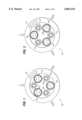
- FIG. 1is a front elevational view of a user-selectable multi-jet assembly in a first, user-selected position
- FIG. 2is a front elevational view of the user-selectable multi-jet assembly of FIG. 1 in a second, user-selected position;
- FIG. 4is a cross-sectional view of second exemplary type nozzle, i.e., a swirling multi-jet nozzle;
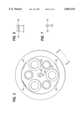
- FIG. 5is rear view of a faceplate assembly of the present invention, the front view being shown in FIGS. 1 and 2;
- FIG. 6is a detail elevational view of a tab structure taken along line 6--6 of FIG. 5;
- FIG. 8is an exploded cross-sectional view of the multi-jet assembly of the present invention.
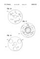
- FIG. 9is a front view of a rear valve plate
- FIG. 10is a front view of a distribution manifold
- FIG. 11is a rear veiw of a front valve plate
- FIG. 12is a front view of the front valve plate of FIG. 11.
- FIG. 1An user-selectable multi-jet assembly for jetted baths/spas in accordance with the present invention is shown in front elevation in FIG. 1 and in FIG. 2 and designated generally therein by the reference character 10.
- the multi-jet assembly 10includes a circular faceplate assembly 12 that carries, in the case of the preferred embodiment, six nozzle stations (unnumbered) equispaced about an axis A x .
- the faceplate assembly 12is bidirectionally rotatable about the axis A x between two user-selectable positions, as represented by the bidirectional arrow. A first position is shown in FIG. 1, and the second position is shown in FIG. 2.
- the rotary movement of the faceplate assembly 12is constrained between defined limits, and the faceplate assembly 12 is held in either of its positions by a detent or by frictional engagement of the cooperating parts.
- three of the nozzle stationscarry a nozzle of a first type, i.e., a user-pointable ball-type nozzle 14 while the remaining three nozzles carry a nozzle of a second type, i.e., a multi-jet swirler-type nozzle 16.
- the ball-type nozzles 14are carried in alternate, non-adjacent nozzle stations, and the swirler-type nozzles 16 occupy the intermediate nozzle stations.
- the faceplate assembly 12can be rotated to the first operative position in which the ball-type nozzles 14 are selected (as indicated by the three, equispaced arrows) and the second operative position in which the swirler-type nozzles 16 are selected.
- the usercan select three pointable ball-type nozzles 14 or three multi-jet swirler-type nozzles 16.
- each ball-type nozzle 14is housed in a nozzle station defined by a cylindrical tube 18 (integrally molded with the faceplate assembly 12) with a retainer cap 20 secured to the end of the cylindrical tube 18.
- the retainer cap 20may be secured to the end of the cylindrical tube 18, for example, by ultrasonic welding or by solvent welding.
- a spheroidal ball 22 having a ball bore 24is carried in the cylindrical tube 18 and resiliently retained in place by a helical spring 26 in compression between the retainer cap 20 and the ball 22. As shown in FIG. 3, the ball bore 24 converges toward the end thereof that faces the user.
- the ball 22may be pointed or oriented in a desired position by the user with the selected position maintained by the helical spring 26.
- the end of a distribution tube 28is shown to the right of the retainer cap 20. As explained in more detail below, pressurized water is directed from the end of the distribution tube 28 into the ball bore 24 with air entrained into the water flow from the distribution tube 28 to provide a water/air mixture through the ball bore 24.
- a generally cylindrical swirl-rotor 30is retained within the nozzle station for rotation about its axis.
- the swirl-rotor 30includes a entry port 32 that separates into three output ports 34 (only one of which is shown in FIG. 4).
- Each output port 34is aligned at an angle relative to and is also skewed relative to the axis of rotation of the swirl-rotor 30 so that the swirl-rotor 30 will rotate in a desired clockwise or counterclockwise direction (depending upon the angular relationship of the output ports 34 to the axis of rotation).
- the end of a distribution tube 28is shown to the right of the retainer cap 20 for the swirler-type nozzle 16.
- Pressurized wateris directed from the distribution tube 28 into the entry port 32 with air entrained into the water flow from the distribution tube 28 to provide a water/air mixture through the output ports 34 to provide three separate water/air streams that swirl or twirl about the axis of rotation of the swirl-rotor 30.
- a front valve plate 36is resiliently pressed or urged against the retainer caps 20 of the various nozzle stations.
- the front valve plate 36includes through openings that co-align with the nozzle stations when the faceplate assembly 12 is rotated by the user to select the ball-type nozzles 14 or select the swirler-type nozzles 16.
- the retainer caps 20are effectively wiped onto a portion of the front valve plate 36 between the through openings to cut off fluid flow through the ball-type nozzles 14 and the swirler-type nozzles 16 while the user is rotating the faceplate assembly 12 from one position to the other.
- a rear valve plateconcurrently interrupts or cuts off water flow through the distribution tubes 28 so that any water flow through the various parts is substantially halted during movement of the faceplate assembly 12 from one position to the other.
- FIG. 5illustrates the rear side of the faceplate assembly 12, i.e., the side opposite that shown in FIG. 1 and FIG. 2.
- the six cylindrical tubes 18are positioned about a coaxially aligned stem 38.
- the stem 38is integrally formed with the faceplate assembly 12 and is formed with a pair of parallel, chordal flats 40.
- the stem 38is designed, as explained below, to connect to and rotate a rear valve plate assembly as the faceplate assembly 12 is rotated by the user to select one set of jets or the other.
- the cylindrical tubes 18 for the swirler-type nozzles 16are of a diameter somewhat larger that the cylindrical tubes 18 for the ball-type nozzles 14.
- Four tabs 42are formed about a selected base circle and, as shown in the details of FIG. 6 and FIG. 7, each tab 42 includes a groove 44 near the remote end thereof. As explained below, the tabs 42 cooperate with a circular ridge (describe below) to assist in securing the parts together.
- FIG. 8illustrates the major components of the multi-jet assembly 10 in exploded form with selected structure omitted for reasons of clarity.
- the left side of the figurerepresents the front or forward end of the multi-jet assembly 10 that faces toward the interior of the tub while the right represents the rear or rearward end of the multi-jet assembly 10.
- the multi-jet assembly 10includes the faceplate assembly 12, described above, a housing 46 into which the major components are assembled, a retaining ring 48, a rotatably mounted rear valve plate 50, and a water control stator 52 that includes a manifold plate 54 and the front valve plate 36 that is biased into the faceplate assembly 12 by a helical spring 56.
- the manifold plate 54carries three distribution tubes 28 (only two of which are shown in FIG. 8) that each conduct water streams provided through the rear valve plate 50 to the faceplate assembly 12.
- the faceplate assembly 12is connected to the rear valve plate 50 through the stem 38 so that rotation of the faceplate assembly 12 by the user also rotates the rear valve plate 50 with water streams directed through the distribution tubes 28 through openings in the front valve plate 36 into the selected nozzle stations of the faceplate assembly 12.
- the faceplate assembly 12 and the connected rear valve plate 50thus define a rotor (unnumbered) that cooperates with the stator 52 to control water flow through the multi-jet assembly 10.
- the rear valve plate 50momentarily interrupts water flow to the distribution tubes 28, and the front valve plate 36 momentarily interrupts flow through the various nozzles.
- the rear valve plate 50is formed as a generally circular member about the axis A x and includes a forwardly extending stem receiver 70 that is formed with an internal profile that accepts the above described stem 38 in a slip-fit torque-transmitting engagement.
- a notch 72along part of its periphery (i.e., about a 60 degree arc).
- a key 74(which is part of the manifold plate 54) is positioned within the notch 72 when the parts are assembled and functions to limit the rotary motion of the rear valve plate 50 and the connected faceplate assembly 12.
- the rear valve plate 50includes six venturi-type openings 76 formed on and equispaced along a base circle having a selected diameter about the axis A x . As shown in the side view of FIG. 8, each venturi-type opening 76 has a profile that converges toward the forward end of the multi-jet assembly 10.
- the manifold plate 54is formed as a generally circular member with external threads 78 designed to engage the internal threads 66 of the housing 46.
- the manifold plate 54includes a counterbore 80 on its rearward side into which the body of the rear valve plate 50 is received and a central opening 82 through which the stem receiver 70 extends when the two parts are assembled.
- the manifold plate 54includes three equispaced distribution tubes 28 and alternating equispaced cylindrical posts 84.
- the rear valve plate 50When the manifold plate 54 is threaded into engagement in the housing 46 with the rear valve plate 50 rotatably captured within the counterbore 80, the rear valve plate 50 is free to rotate between its two user selectable positions with one set of three venturi-type openings 76 aligned with the distribution tubes 28 or the other set of three venturi-type openings 76 aligned with the distribution tubes 28.
- the above-described key 74which is integrally molded at the periphery of the counterbore 80, cooperates with the notch 72 to limit the rotary motion of the rear valve plate 50 within the counterbore 80 of the manifold plate 54 to about a 60° arc.
- the venturi-type openings 76are aligned with the three distribution tubes 28 so that water under pressure will flow through the venturi-type openings 76 into the co-aligned distribution tubes 28 and through the selected nozzles.
- the venturi-type openings 76are no longer co-aligned with the distribution tubes 28 and, accordingly, water flow through the distribution tubes 28 is momentarily interrupted.
- FIG. 11is a rearward view of the front valve plate 36 and, as shown, the front valve plate 36 is formed as a generally circular member about the axis A x .
- the front valve plate 36includes three openings 86 equispaced on a common diameter and three similarly spaced post-receiving members 88.
- the post-receiving members 88are each formed as a hollow cylinder having a cylindrically extending bore 90 that is designed to receive the post 84 of the manifold plate 54 in a sliding fit engagement.
- An annular wall 92extends rearwardly from the rear surface of the front valve plate 36 and surrounds a center opening 94 through which the stem receiver 70 of the rear valve plate 50 extends.
- the helical spring 56is contained within the cavity defined by the annular wall 92 and, when the stator 52 is assembled, is designed to resiliently urge the forward-facing surface of the front valve plate 36 against the retainer caps 20 at the rearward end of the faceplate assembly 12.
- the posts 84 on the front valve plate 36are received within the post-receiving members 88 of the manifold plate 54 to allow a measure of forward and rearward movement along the axis A x .
- the retaining ring 48includes external threads 96 that mate with the internal threads 68 of the housing 48. As shown on the right side of FIG. 8 in dotted-line illustration, the retaining ring 48 includes a retaining flange 98 that clamps the tub wall 100 (dotted-line illustration) to the housing 46. The retaining ring 48 includes an internal ridge 102 that is designed to mate with the above-described groove 44 of the tabs 42 (FIGS. 6 and 7) of the faceplate assembly 12 in a snap-fit relationship.
- the multi-jet assembly 10is assembled by threading the retaining ring 48 into the internal threads 68 of the housing 46.
- the rear valve plate 50is positioned in the counterbore 80 of the manifold plate 54.
- the manifold plate 54is then threaded into the internal threads 66 of the housing 46 with the above-described key 74 located in the notch 72.
- the manifold plate 54can thus be freely rotated about the axis A x within the arc defined by the notch 72 with engagement between the key 74 and the ends of the notch 72 defining the limits of movement.
- the helical spring 56is placed into the cavity defined by the annular wall 92 and the posts 84 of the front valve plate 36 (not shown in FIG.
- the faceplate assembly 12is inserted into the retaining ring 48 with its stem 38 inserted into and received by the stem receiver 70 of the rear valve plate 50.
- the faceplate assembly 12is pressed into the retaining ring 48 until the groove 44 on each of the tabs 42 snaps into engagement with the ridge 102 formed on the interior wall of the retaining ring 48.
- the front surface of the front valve plate 36is resiliently biased into engagement with the rear surfaces of the retainer caps 20 of the various nozzle stations by the helical spring 56.
- the stem 38 and stem receiver 70 connectionalso rotates the rear valve plate 50 captured in the manifold plate 54.
- water under pressure in the water chamber 60will pass through three of the six venturi-type openings 76 of the rear valve plate 50, through the co-aligned distribution tubes 28, and through the openings 86 of the front valve plate 36 toward and into the ball bores 24 of the ball-type nozzle 14.
- air within the air plenum 64will be entrained within the air stream as it enters the ball bore 24 and passes through the ball bore 24 into the interior of the tub to provide three user-pointable water/air streams.
- the faceplate assembly 12rotates within the retaining ring 48 with the rear surface of the retainer caps 20 wiping across the front surface of the front valve plate 36 intermediate the openings 86.
- the retainer caps 20 for the ball-type nozzles 14move out of alignment with the openings 86 and onto the front surface of the front valve plate 36 between positions, any flow through the various nozzle stations is cut off or interrupted.
- the rear valve plate 50, through the stem 38 and stem receiver 70 connectionalso simultaneously rotates with the faceplate assembly 12.
- the three venturi-type openings 76 that were co-aligned with the three distribution tubes 28wipe across the rear surface of the counterbore 80 to substantially interrupt water flow into the distribution tubes 28 as the faceplate assembly 12 is being moved from one position to the other position by the user.
- the rear surface of the retainer caps 20 for the swirler-type nozzles 16will co-align with the openings 86 of the front valve plate 36.
- the rear valve plate 50, through the stem 38 and stem receiver 70 connectionwill simultaneously rotate with the faceplate assembly 12.
- three venturi-type openings 76will co-align with the three distribution tubes 28 to resume water flow through each of the distribution tubes 28 into the entry ports 32 of the swirl-rotors 30.
- the userWhen rotating the faceplate assembly 12 between nozzle-selection positions, the user will observe a near complete interruption of water flow as the faceplate assembly 12 is moved away from one nozzle position toward the other nozzle position followed by a resumption of flow when the faceplate assembly 12 moves into the other nozzle position.
- the present inventionadvantageously provides an user-selectable multi-jet assembly for jetted baths/spas in which the user can easily and conveniently select one of a plurality of nozzle types.
Landscapes
- Health & Medical Sciences (AREA)
- Public Health (AREA)
- Epidemiology (AREA)
- Pain & Pain Management (AREA)
- Physical Education & Sports Medicine (AREA)
- Rehabilitation Therapy (AREA)
- Life Sciences & Earth Sciences (AREA)
- Animal Behavior & Ethology (AREA)
- General Health & Medical Sciences (AREA)
- Veterinary Medicine (AREA)
- Nozzles (AREA)
Abstract
Description
Claims (9)
Priority Applications (1)
| Application Number | Priority Date | Filing Date | Title |
|---|---|---|---|
| US08/966,410US5862543A (en) | 1997-11-07 | 1997-11-07 | User-selectable multi-jet assembly for jetted baths/spas |
Applications Claiming Priority (1)
| Application Number | Priority Date | Filing Date | Title |
|---|---|---|---|
| US08/966,410US5862543A (en) | 1997-11-07 | 1997-11-07 | User-selectable multi-jet assembly for jetted baths/spas |
Publications (1)
| Publication Number | Publication Date |
|---|---|
| US5862543Atrue US5862543A (en) | 1999-01-26 |
Family
ID=25511360
Family Applications (1)
| Application Number | Title | Priority Date | Filing Date |
|---|---|---|---|
| US08/966,410Expired - Fee RelatedUS5862543A (en) | 1997-11-07 | 1997-11-07 | User-selectable multi-jet assembly for jetted baths/spas |
Country Status (1)
| Country | Link |
|---|---|
| US (1) | US5862543A (en) |
Cited By (85)
| Publication number | Priority date | Publication date | Assignee | Title |
|---|---|---|---|---|
| US5915849A (en)* | 1997-11-20 | 1999-06-29 | B&S Plastics, Inc. | Selectable hydrotherapy jet system |
| US6141804A (en)* | 1999-06-04 | 2000-11-07 | Pinciaro; John | Hydrotherapy jet system adapted for quick connection to air and water plumbing |
| US6185757B1 (en) | 1999-06-24 | 2001-02-13 | Saratoga Spa & Bath Co., Inc. | Manual control of water delivery through ports of tub, spa or shower |
| USD450804S1 (en) | 2000-06-06 | 2001-11-20 | Bowles Fluidics Corporation | Fluidic spa nozzle |
| US6357059B1 (en)* | 2000-03-28 | 2002-03-19 | Pleasure Time Products (Hk) Limited | Portable spa |
| US6490740B1 (en) | 1999-06-24 | 2002-12-10 | Saratoga Spa & Bath Co., Inc. | Motorized control of water delivery through ports of tub, spa or shower |
| US6578207B1 (en) | 2001-10-09 | 2003-06-17 | Eric L. Fratilla | Return jet fitting for pools and spas |
| US6643859B1 (en) | 2001-05-15 | 2003-11-11 | Saratoga Spa & Bath Co., Inc. | Fluid flow system with flow diverter |
| US20040074993A1 (en)* | 2000-12-12 | 2004-04-22 | Thomas Gary J. | Shower head assembly |
| US6770043B1 (en) | 2000-04-28 | 2004-08-03 | Rocky Kahn | Hydrotherapy system with translating jets |
| US20040195381A1 (en)* | 2002-12-10 | 2004-10-07 | Luettgen Harold A. | Dual massage shower head |
| US6848637B2 (en)* | 2002-06-05 | 2005-02-01 | Waterway Plastics, Inc. | Hydrotherapy jet with rotating outlet |
| US20050055762A1 (en)* | 2003-09-17 | 2005-03-17 | Cheng-Chung Wang | Swirling bathing tub |
| US20050082824A1 (en)* | 2003-10-14 | 2005-04-21 | Luettgen Harold A. | Rotatable and pivotable connector |
| US20050120473A1 (en)* | 2003-09-23 | 2005-06-09 | Brian Southon | Hydrotherapy circulation and cleaning system |
| US20050199275A1 (en)* | 2004-03-10 | 2005-09-15 | Abbott W.T. D. | System for cleaning components of a water retaining device, associated water retaining device, and water propulsion device for use therein |
| US6957451B2 (en) | 1999-06-24 | 2005-10-25 | Saratoga Spa & Bath, Inc. | Flow control device for tub, spa, or shower |
| US7070129B1 (en) | 1999-06-24 | 2006-07-04 | Bowles Fluidics Corporation | Spa tub fluidic nozzles |
| USD527440S1 (en) | 2004-09-01 | 2006-08-29 | Water Pik, Inc. | Drenching shower head |
| USD528631S1 (en) | 2000-12-12 | 2006-09-19 | Water Pik, Inc. | Pan head shower head |
| US20060260038A1 (en)* | 2005-05-23 | 2006-11-23 | Lau Vincent W | Portable spa |
| USD533253S1 (en) | 2004-11-03 | 2006-12-05 | Water Pik, Inc. | Elliptical shower head |
| US20070136943A1 (en)* | 2005-12-20 | 2007-06-21 | Long Christopher L | Water jet mechanism for whirlpool effect in pedicures or other applications |
| US20070192952A1 (en)* | 2005-05-23 | 2007-08-23 | Lau Vincent W | Portable spa |
| US20070246577A1 (en)* | 2006-04-20 | 2007-10-25 | Leber Leland C | Converging spray showerhead |
| US20070289056A1 (en)* | 2006-06-15 | 2007-12-20 | Arturo Reynoso | Apparatus and method for jet aeration |
| USD573715S1 (en) | 2006-05-25 | 2008-07-22 | B & S Plastics, Inc. | Fixture for pool or spa |
| USD574501S1 (en) | 2007-06-25 | 2008-08-05 | B & S Plastics, Inc. | Fixture for a pool or spa |
| USD574964S1 (en) | 2006-05-25 | 2008-08-12 | B & S Plastics, Inc. | Fixture for a pool or spa |
| USD577099S1 (en) | 2006-11-29 | 2008-09-16 | Water Pik, Inc. | Showerhead assembly |
| USD577793S1 (en) | 2006-11-29 | 2008-09-30 | Water Pik, Inc. | Showerhead assembly |
| US7434277B1 (en) | 2002-01-23 | 2008-10-14 | Saratoga Spa & Bath, Inc. | Fluid flow system |
| USD580012S1 (en) | 2007-12-20 | 2008-11-04 | Water Pik, Inc. | Showerhead |
| US20080272203A1 (en)* | 2007-05-04 | 2008-11-06 | Water Pik, Inc. | Low flow showerhead and method of making same |
| USD580513S1 (en) | 2007-12-20 | 2008-11-11 | Water Pik, Inc. | Hand shower |
| USD581014S1 (en) | 2007-12-20 | 2008-11-18 | Water Pik, Inc. | Hand shower |
| USD590048S1 (en) | 2007-12-20 | 2009-04-07 | Water Pik, Inc. | Hand shower |
| USD591863S1 (en) | 2006-05-25 | 2009-05-05 | B & S Plastics, Inc. | Fixture for a pool or spa |
| USD592278S1 (en) | 2007-12-20 | 2009-05-12 | Water Pik, Inc. | Showerhead |
| USD600777S1 (en) | 2008-09-29 | 2009-09-22 | Water Pik, Inc. | Showerhead assembly |
| USD603935S1 (en) | 2007-12-20 | 2009-11-10 | Water Pik, Inc. | Hand shower |
| USD605731S1 (en) | 2007-12-26 | 2009-12-08 | Water Pik, Inc. | Bracket for hand shower |
| USD606623S1 (en) | 2008-09-29 | 2009-12-22 | Water Pik, Inc. | Hand shower |
| USD616061S1 (en) | 2008-09-29 | 2010-05-18 | Water Pik, Inc. | Showerhead assembly |
| US20100127096A1 (en)* | 2006-12-28 | 2010-05-27 | Water Pik, Inc. | Low-speed pulsating showerhead |
| US7740186B2 (en) | 2004-09-01 | 2010-06-22 | Water Pik, Inc. | Drenching shower head |
| US7770822B2 (en) | 2006-12-28 | 2010-08-10 | Water Pik, Inc. | Hand shower with an extendable handle |
| US7789326B2 (en) | 2006-12-29 | 2010-09-07 | Water Pik, Inc. | Handheld showerhead with mode control and method of selecting a handheld showerhead mode |
| USD624156S1 (en) | 2008-04-30 | 2010-09-21 | Water Pik, Inc. | Pivot ball attachment |
| USD625776S1 (en) | 2009-10-05 | 2010-10-19 | Water Pik, Inc. | Showerhead |
| US20100301130A1 (en)* | 2009-06-01 | 2010-12-02 | Nelson Irrigation Corporation | Automatic nozzle changer |
| US8020787B2 (en) | 2006-11-29 | 2011-09-20 | Water Pik, Inc. | Showerhead system |
| US8095998B2 (en) | 2005-05-23 | 2012-01-17 | Ideal Time Consultants Limited | Portable spa |
| USD673649S1 (en) | 2012-01-27 | 2013-01-01 | Water Pik, Inc. | Ring-shaped wall mount showerhead |
| USD674050S1 (en) | 2012-01-27 | 2013-01-08 | Water Pik, Inc. | Ring-shaped handheld showerhead |
| US8348181B2 (en) | 2008-09-15 | 2013-01-08 | Water Pik, Inc. | Shower assembly with radial mode changer |
| US8366024B2 (en) | 2006-12-28 | 2013-02-05 | Water Pik, Inc. | Low speed pulsating showerhead |
| US8616470B2 (en) | 2010-08-25 | 2013-12-31 | Water Pik, Inc. | Mode control valve in showerhead connector |
| US8695128B1 (en) | 2011-01-10 | 2014-04-15 | Richard Jeffrey Busbey | Adjustable return fitting |
| CN103862871A (en)* | 2012-12-11 | 2014-06-18 | 三星显示有限公司 | printer |
| US8944786B1 (en) | 2009-07-17 | 2015-02-03 | Eugene McDougall | Low energy magnetic spa circulation system |
| USD744066S1 (en) | 2014-06-13 | 2015-11-24 | Water Pik, Inc. | Wall mount showerhead |
| USD744064S1 (en) | 2014-06-13 | 2015-11-24 | Water Pik, Inc. | Handheld showerhead |
| USD744065S1 (en) | 2014-06-13 | 2015-11-24 | Water Pik, Inc. | Handheld showerhead |
| USD744611S1 (en) | 2014-06-13 | 2015-12-01 | Water Pik, Inc. | Handheld showerhead |
| USD744612S1 (en) | 2014-06-13 | 2015-12-01 | Water Pik, Inc. | Handheld showerhead |
| USD744614S1 (en) | 2014-06-13 | 2015-12-01 | Water Pik, Inc. | Wall mount showerhead |
| USD745111S1 (en) | 2014-06-13 | 2015-12-08 | Water Pik, Inc. | Wall mount showerhead |
| US9364389B1 (en) | 2014-04-30 | 2016-06-14 | Mansfield Plumbing Products, Llc | Hygienic water jet assembly |
| US9404243B2 (en) | 2013-06-13 | 2016-08-02 | Water Pik, Inc. | Showerhead with turbine driven shutter |
| US20160220778A1 (en)* | 2012-01-23 | 2016-08-04 | Aeon Research And Technology, Inc. | Gas delivery venturi |
| USD780319S1 (en)* | 2010-04-12 | 2017-02-28 | Pentair Water Pool And Spa, Inc. | Front face for an illuminating water bubbler |
| USD803981S1 (en) | 2016-02-01 | 2017-11-28 | Water Pik, Inc. | Handheld spray nozzle |
| US9979182B2 (en) | 2014-02-24 | 2018-05-22 | Intex Marketing Ltd. | Wave-making mechanism |
| US10226777B2 (en) | 2012-06-22 | 2019-03-12 | Water Pik, Inc. | Showerhead bracket |
| USD843549S1 (en) | 2017-07-19 | 2019-03-19 | Water Pik, Inc. | Handheld spray nozzle |
| US10265710B2 (en) | 2016-04-15 | 2019-04-23 | Water Pik, Inc. | Showerhead with dual oscillating massage |
| US10441960B2 (en) | 2016-09-08 | 2019-10-15 | Water Pik, Inc. | Pause assembly for showerheads |
| US10449558B2 (en) | 2016-02-01 | 2019-10-22 | Water Pik, Inc. | Handheld pet spray wand |
| USD872227S1 (en) | 2018-04-20 | 2020-01-07 | Water Pik, Inc. | Handheld spray device |
| US10960282B2 (en) | 2017-01-11 | 2021-03-30 | Intex Marketing Ltd. | Pool with an annular lane |
| US20210129002A1 (en) | 2019-11-01 | 2021-05-06 | Intex Industries Xiamen Co. Ltd. | Attachment structure for a swimming machine |
| USD970684S1 (en) | 2016-04-15 | 2022-11-22 | Water Pik, Inc. | Showerhead |
| US11583743B2 (en) | 2017-06-22 | 2023-02-21 | Intex Marketing Ltd. | Adjustable hanging assembly for flow generating device |
| US20240156679A1 (en)* | 2022-11-10 | 2024-05-16 | Bullfrog International, Lc | Systems and methods for a multi pattern spa jet |
Citations (2)
| Publication number | Priority date | Publication date | Assignee | Title |
|---|---|---|---|---|
| US659714A (en)* | 1897-08-09 | 1900-10-16 | Charles William Storm | Hose-nozzle. |
| JPH03253627A (en)* | 1990-03-02 | 1991-11-12 | Toto Ltd | Spray-foam switching drain port |
- 1997
- 1997-11-07USUS08/966,410patent/US5862543A/ennot_activeExpired - Fee Related
Patent Citations (2)
| Publication number | Priority date | Publication date | Assignee | Title |
|---|---|---|---|---|
| US659714A (en)* | 1897-08-09 | 1900-10-16 | Charles William Storm | Hose-nozzle. |
| JPH03253627A (en)* | 1990-03-02 | 1991-11-12 | Toto Ltd | Spray-foam switching drain port |
Cited By (151)
| Publication number | Priority date | Publication date | Assignee | Title |
|---|---|---|---|---|
| US5915849A (en)* | 1997-11-20 | 1999-06-29 | B&S Plastics, Inc. | Selectable hydrotherapy jet system |
| US6141804A (en)* | 1999-06-04 | 2000-11-07 | Pinciaro; John | Hydrotherapy jet system adapted for quick connection to air and water plumbing |
| US6662384B1 (en) | 1999-06-24 | 2003-12-16 | Saratoga Spa & Bath Co., Inc. | Motorized control of water delivery through ports of tub, Spa of shower |
| US6185757B1 (en) | 1999-06-24 | 2001-02-13 | Saratoga Spa & Bath Co., Inc. | Manual control of water delivery through ports of tub, spa or shower |
| US7070129B1 (en) | 1999-06-24 | 2006-07-04 | Bowles Fluidics Corporation | Spa tub fluidic nozzles |
| US6957451B2 (en) | 1999-06-24 | 2005-10-25 | Saratoga Spa & Bath, Inc. | Flow control device for tub, spa, or shower |
| US6490740B1 (en) | 1999-06-24 | 2002-12-10 | Saratoga Spa & Bath Co., Inc. | Motorized control of water delivery through ports of tub, spa or shower |
| US6357059B1 (en)* | 2000-03-28 | 2002-03-19 | Pleasure Time Products (Hk) Limited | Portable spa |
| US6770043B1 (en) | 2000-04-28 | 2004-08-03 | Rocky Kahn | Hydrotherapy system with translating jets |
| USD450804S1 (en) | 2000-06-06 | 2001-11-20 | Bowles Fluidics Corporation | Fluidic spa nozzle |
| US20040074993A1 (en)* | 2000-12-12 | 2004-04-22 | Thomas Gary J. | Shower head assembly |
| US7111798B2 (en) | 2000-12-12 | 2006-09-26 | Thomas Gary J | Shower head assembly |
| USD528631S1 (en) | 2000-12-12 | 2006-09-19 | Water Pik, Inc. | Pan head shower head |
| US6643859B1 (en) | 2001-05-15 | 2003-11-11 | Saratoga Spa & Bath Co., Inc. | Fluid flow system with flow diverter |
| US6578207B1 (en) | 2001-10-09 | 2003-06-17 | Eric L. Fratilla | Return jet fitting for pools and spas |
| US7434277B1 (en) | 2002-01-23 | 2008-10-14 | Saratoga Spa & Bath, Inc. | Fluid flow system |
| US6848637B2 (en)* | 2002-06-05 | 2005-02-01 | Waterway Plastics, Inc. | Hydrotherapy jet with rotating outlet |
| US8905332B2 (en) | 2002-12-10 | 2014-12-09 | Water Pik, Inc. | Dual turbine showerhead |
| US9795975B2 (en) | 2002-12-10 | 2017-10-24 | Water Pik, Inc. | Dual turbine showerhead |
| US20110121098A1 (en)* | 2002-12-10 | 2011-05-26 | Water Pik, Inc. | Dual turbine showerhead |
| US8020788B2 (en) | 2002-12-10 | 2011-09-20 | Water Pik, Inc. | Showerhead with enhanced pause mode |
| US7520448B2 (en) | 2002-12-10 | 2009-04-21 | Water Pik, Inc. | Shower head with enhanced pause mode |
| US20050061896A1 (en)* | 2002-12-10 | 2005-03-24 | Luettgen Harold A. | Shower head with enhanced pause mode |
| US7114666B2 (en) | 2002-12-10 | 2006-10-03 | Water Pik, Inc. | Dual massage shower head |
| US20040195381A1 (en)* | 2002-12-10 | 2004-10-07 | Luettgen Harold A. | Dual massage shower head |
| US20050055762A1 (en)* | 2003-09-17 | 2005-03-17 | Cheng-Chung Wang | Swirling bathing tub |
| US7334274B2 (en)* | 2003-09-17 | 2008-02-26 | Cheng-Chung Wang | Swirling bathing tub |
| US20050120473A1 (en)* | 2003-09-23 | 2005-06-09 | Brian Southon | Hydrotherapy circulation and cleaning system |
| US7533906B2 (en) | 2003-10-14 | 2009-05-19 | Water Pik, Inc. | Rotatable and pivotable connector |
| US20050082824A1 (en)* | 2003-10-14 | 2005-04-21 | Luettgen Harold A. | Rotatable and pivotable connector |
| US7182090B2 (en)* | 2004-03-10 | 2007-02-27 | Abbott W T David | System for cleaning components of a water retaining device, associated water retaining device, and water propulsion device for use therein |
| US20050199275A1 (en)* | 2004-03-10 | 2005-09-15 | Abbott W.T. D. | System for cleaning components of a water retaining device, associated water retaining device, and water propulsion device for use therein |
| USD527440S1 (en) | 2004-09-01 | 2006-08-29 | Water Pik, Inc. | Drenching shower head |
| US7740186B2 (en) | 2004-09-01 | 2010-06-22 | Water Pik, Inc. | Drenching shower head |
| US20110011953A1 (en)* | 2004-09-01 | 2011-01-20 | Water Pik, Inc. | Drenching Showerhead |
| US8292200B2 (en) | 2004-09-01 | 2012-10-23 | Water Pik, Inc. | Drenching showerhead |
| USD533253S1 (en) | 2004-11-03 | 2006-12-05 | Water Pik, Inc. | Elliptical shower head |
| US8108954B2 (en) | 2005-05-23 | 2012-02-07 | Ideal Time Consultants Limited | Portable spa |
| US20110010836A1 (en)* | 2005-05-23 | 2011-01-20 | Ideal Time Consultants Ltd. | Portable spa |
| US20060260039A1 (en)* | 2005-05-23 | 2006-11-23 | Lau Vincent W | Portable spa |
| US7797770B2 (en) | 2005-05-23 | 2010-09-21 | Ideal Time Consultants. Limited | Portable spa |
| US7818825B2 (en) | 2005-05-23 | 2010-10-26 | Ideal Time Consultants Limited | Portable spa |
| US8095998B2 (en) | 2005-05-23 | 2012-01-17 | Ideal Time Consultants Limited | Portable spa |
| US20060260038A1 (en)* | 2005-05-23 | 2006-11-23 | Lau Vincent W | Portable spa |
| US20070192952A1 (en)* | 2005-05-23 | 2007-08-23 | Lau Vincent W | Portable spa |
| USRE45844E1 (en) | 2005-12-20 | 2016-01-19 | Lexor, Inc. | Water jet mechanism for whirlpool effect in pedicures or other applications |
| USRE46655E1 (en) | 2005-12-20 | 2018-01-02 | Lexor, Inc. | Water jet mechanism for whirlpool effect in pedicures or other applications |
| US20070136943A1 (en)* | 2005-12-20 | 2007-06-21 | Long Christopher L | Water jet mechanism for whirlpool effect in pedicures or other applications |
| US8733675B2 (en) | 2006-04-20 | 2014-05-27 | Water Pik, Inc. | Converging spray showerhead |
| US20070246577A1 (en)* | 2006-04-20 | 2007-10-25 | Leber Leland C | Converging spray showerhead |
| USD591863S1 (en) | 2006-05-25 | 2009-05-05 | B & S Plastics, Inc. | Fixture for a pool or spa |
| USD574964S1 (en) | 2006-05-25 | 2008-08-12 | B & S Plastics, Inc. | Fixture for a pool or spa |
| USD573715S1 (en) | 2006-05-25 | 2008-07-22 | B & S Plastics, Inc. | Fixture for pool or spa |
| US20070289056A1 (en)* | 2006-06-15 | 2007-12-20 | Arturo Reynoso | Apparatus and method for jet aeration |
| US7743437B2 (en) | 2006-06-15 | 2010-06-29 | G-G Distribution And Development Co., Inc. | Apparatus and method for jet aeration |
| USD577099S1 (en) | 2006-11-29 | 2008-09-16 | Water Pik, Inc. | Showerhead assembly |
| US20110000982A1 (en)* | 2006-11-29 | 2011-01-06 | Water Pik, Inc. | Connection Structure for Handheld Showerhead |
| USD577793S1 (en) | 2006-11-29 | 2008-09-30 | Water Pik, Inc. | Showerhead assembly |
| US8132745B2 (en) | 2006-11-29 | 2012-03-13 | Water Pik, Inc. | Showerhead with tube connectors |
| US8109450B2 (en) | 2006-11-29 | 2012-02-07 | Water Pik, Inc. | Connection structure for handheld showerhead |
| US8020787B2 (en) | 2006-11-29 | 2011-09-20 | Water Pik, Inc. | Showerhead system |
| US7770822B2 (en) | 2006-12-28 | 2010-08-10 | Water Pik, Inc. | Hand shower with an extendable handle |
| US8794543B2 (en) | 2006-12-28 | 2014-08-05 | Water Pik, Inc. | Low-speed pulsating showerhead |
| US20100127096A1 (en)* | 2006-12-28 | 2010-05-27 | Water Pik, Inc. | Low-speed pulsating showerhead |
| US8366024B2 (en) | 2006-12-28 | 2013-02-05 | Water Pik, Inc. | Low speed pulsating showerhead |
| US8584972B2 (en) | 2006-12-29 | 2013-11-19 | Water Pik, Inc. | Handheld showerhead with fluid passageways |
| US9623424B2 (en) | 2006-12-29 | 2017-04-18 | Water Pik, Inc. | Handheld showerhead with mode selector in handle |
| US8146838B2 (en) | 2006-12-29 | 2012-04-03 | Water Pik, Inc. | Handheld showerhead with mode control in handle |
| US8967497B2 (en) | 2006-12-29 | 2015-03-03 | Water Pik, Inc. | Handheld showerhead with mode selector in handle |
| US9636694B2 (en) | 2006-12-29 | 2017-05-02 | Water Pik, Inc. | Showerhead with movable control valve |
| US20100320290A1 (en)* | 2006-12-29 | 2010-12-23 | Water Pik, Inc. | Handheld showerhead with mode control in handle |
| US7789326B2 (en) | 2006-12-29 | 2010-09-07 | Water Pik, Inc. | Handheld showerhead with mode control and method of selecting a handheld showerhead mode |
| US9623425B2 (en) | 2006-12-29 | 2017-04-18 | Water Pik, Inc. | Showerhead with rotatable control valve |
| US20080272203A1 (en)* | 2007-05-04 | 2008-11-06 | Water Pik, Inc. | Low flow showerhead and method of making same |
| US20080272591A1 (en)* | 2007-05-04 | 2008-11-06 | Water Pik, Inc. | Hidden pivot attachment for showers and method of making same |
| US8028935B2 (en) | 2007-05-04 | 2011-10-04 | Water Pik, Inc. | Low flow showerhead and method of making same |
| US9127794B2 (en) | 2007-05-04 | 2015-09-08 | Water Pik, Inc. | Pivot attachment for showerheads |
| US8371618B2 (en) | 2007-05-04 | 2013-02-12 | Water Pik, Inc. | Hidden pivot attachment for showers and method of making same |
| USD574501S1 (en) | 2007-06-25 | 2008-08-05 | B & S Plastics, Inc. | Fixture for a pool or spa |
| USD580012S1 (en) | 2007-12-20 | 2008-11-04 | Water Pik, Inc. | Showerhead |
| USD590048S1 (en) | 2007-12-20 | 2009-04-07 | Water Pik, Inc. | Hand shower |
| USD603935S1 (en) | 2007-12-20 | 2009-11-10 | Water Pik, Inc. | Hand shower |
| USD580513S1 (en) | 2007-12-20 | 2008-11-11 | Water Pik, Inc. | Hand shower |
| USD592278S1 (en) | 2007-12-20 | 2009-05-12 | Water Pik, Inc. | Showerhead |
| USD581014S1 (en) | 2007-12-20 | 2008-11-18 | Water Pik, Inc. | Hand shower |
| USD605731S1 (en) | 2007-12-26 | 2009-12-08 | Water Pik, Inc. | Bracket for hand shower |
| USD624156S1 (en) | 2008-04-30 | 2010-09-21 | Water Pik, Inc. | Pivot ball attachment |
| US8348181B2 (en) | 2008-09-15 | 2013-01-08 | Water Pik, Inc. | Shower assembly with radial mode changer |
| US8757517B2 (en) | 2008-09-15 | 2014-06-24 | Water Pik, Inc. | Showerhead with flow directing plates and radial mode changer |
| USD606623S1 (en) | 2008-09-29 | 2009-12-22 | Water Pik, Inc. | Hand shower |
| USD600777S1 (en) | 2008-09-29 | 2009-09-22 | Water Pik, Inc. | Showerhead assembly |
| USD616061S1 (en) | 2008-09-29 | 2010-05-18 | Water Pik, Inc. | Showerhead assembly |
| US20100301130A1 (en)* | 2009-06-01 | 2010-12-02 | Nelson Irrigation Corporation | Automatic nozzle changer |
| US9085005B2 (en)* | 2009-06-01 | 2015-07-21 | Nelson Irrigation Corporation | Automatic nozzle changer |
| US8944786B1 (en) | 2009-07-17 | 2015-02-03 | Eugene McDougall | Low energy magnetic spa circulation system |
| USD625776S1 (en) | 2009-10-05 | 2010-10-19 | Water Pik, Inc. | Showerhead |
| USD641831S1 (en) | 2009-10-05 | 2011-07-19 | Water Pik, Inc. | Showerhead |
| USD780319S1 (en)* | 2010-04-12 | 2017-02-28 | Pentair Water Pool And Spa, Inc. | Front face for an illuminating water bubbler |
| US8616470B2 (en) | 2010-08-25 | 2013-12-31 | Water Pik, Inc. | Mode control valve in showerhead connector |
| US8695128B1 (en) | 2011-01-10 | 2014-04-15 | Richard Jeffrey Busbey | Adjustable return fitting |
| US9161883B1 (en)* | 2011-01-10 | 2015-10-20 | R. Jeffrey Busbey | Adjustable return fitting |
| US20160220778A1 (en)* | 2012-01-23 | 2016-08-04 | Aeon Research And Technology, Inc. | Gas delivery venturi |
| US10052451B2 (en)* | 2012-01-23 | 2018-08-21 | Aeon Research And Technology, Inc. | Gas delivery venturi |
| USD678467S1 (en) | 2012-01-27 | 2013-03-19 | Water Pik, Inc. | Ring-shaped handheld showerhead |
| USD673649S1 (en) | 2012-01-27 | 2013-01-01 | Water Pik, Inc. | Ring-shaped wall mount showerhead |
| USD674050S1 (en) | 2012-01-27 | 2013-01-08 | Water Pik, Inc. | Ring-shaped handheld showerhead |
| USD678463S1 (en) | 2012-01-27 | 2013-03-19 | Water Pik, Inc. | Ring-shaped wall mount showerhead |
| US10226777B2 (en) | 2012-06-22 | 2019-03-12 | Water Pik, Inc. | Showerhead bracket |
| US10532369B2 (en) | 2012-06-22 | 2020-01-14 | Water Pik, Inc. | Showerhead bracket |
| CN103862871B (en)* | 2012-12-11 | 2017-04-12 | 三星显示有限公司 | Printer |
| CN103862871A (en)* | 2012-12-11 | 2014-06-18 | 三星显示有限公司 | printer |
| US9404243B2 (en) | 2013-06-13 | 2016-08-02 | Water Pik, Inc. | Showerhead with turbine driven shutter |
| US10994289B2 (en) | 2013-06-13 | 2021-05-04 | Water Pik, Inc. | Showerhead with turbine driven shutter |
| US11648573B2 (en) | 2013-06-13 | 2023-05-16 | Water Pik, Inc. | Showerhead |
| US10525488B2 (en) | 2013-06-13 | 2020-01-07 | Water Pik, Inc. | Showerhead with engine release assembly |
| US10478837B2 (en) | 2013-06-13 | 2019-11-19 | Water Pik, Inc. | Method for assembling a showerhead |
| US11173502B2 (en) | 2013-06-13 | 2021-11-16 | Water Pik, Inc. | Showerhead with plurality of modes |
| US10193329B2 (en) | 2014-02-24 | 2019-01-29 | Intex Marketing Ltd. | Wave-making mechanism |
| US9979182B2 (en) | 2014-02-24 | 2018-05-22 | Intex Marketing Ltd. | Wave-making mechanism |
| US9364389B1 (en) | 2014-04-30 | 2016-06-14 | Mansfield Plumbing Products, Llc | Hygienic water jet assembly |
| USD744611S1 (en) | 2014-06-13 | 2015-12-01 | Water Pik, Inc. | Handheld showerhead |
| USD744066S1 (en) | 2014-06-13 | 2015-11-24 | Water Pik, Inc. | Wall mount showerhead |
| USD744064S1 (en) | 2014-06-13 | 2015-11-24 | Water Pik, Inc. | Handheld showerhead |
| USD745111S1 (en) | 2014-06-13 | 2015-12-08 | Water Pik, Inc. | Wall mount showerhead |
| USD744614S1 (en) | 2014-06-13 | 2015-12-01 | Water Pik, Inc. | Wall mount showerhead |
| USD744612S1 (en) | 2014-06-13 | 2015-12-01 | Water Pik, Inc. | Handheld showerhead |
| USD744065S1 (en) | 2014-06-13 | 2015-11-24 | Water Pik, Inc. | Handheld showerhead |
| US11413632B2 (en) | 2016-02-01 | 2022-08-16 | Water Pik, Inc. | Handheld showerhead with linear nozzle arrays |
| USD803981S1 (en) | 2016-02-01 | 2017-11-28 | Water Pik, Inc. | Handheld spray nozzle |
| US10449558B2 (en) | 2016-02-01 | 2019-10-22 | Water Pik, Inc. | Handheld pet spray wand |
| US11883834B2 (en) | 2016-02-01 | 2024-01-30 | Water Pik, Inc. | Handheld showerhead with linear nozzle arrays |
| US11084047B2 (en) | 2016-04-15 | 2021-08-10 | Water Pik, Inc. | Showerhead with dual oscillating massage |
| USD983322S1 (en) | 2016-04-15 | 2023-04-11 | Water Pik, Inc. | Showerhead |
| US10265710B2 (en) | 2016-04-15 | 2019-04-23 | Water Pik, Inc. | Showerhead with dual oscillating massage |
| USD950011S1 (en) | 2016-04-15 | 2022-04-26 | Water Pik, Inc. | Showerhead with dual oscillating massage |
| USD1029184S1 (en) | 2016-04-15 | 2024-05-28 | Water Pik, Inc. | Showerhead |
| USD970684S1 (en) | 2016-04-15 | 2022-11-22 | Water Pik, Inc. | Showerhead |
| USD902348S1 (en) | 2016-09-08 | 2020-11-17 | Water Pik, Inc. | Handheld spray nozzle |
| US11759801B2 (en) | 2016-09-08 | 2023-09-19 | Water Pik, Inc. | Pause assembly for showerheads |
| US10441960B2 (en) | 2016-09-08 | 2019-10-15 | Water Pik, Inc. | Pause assembly for showerheads |
| US11458488B2 (en) | 2016-09-08 | 2022-10-04 | Water Pik, Inc. | Linearly actuated pause assembly for showerheads |
| US10960282B2 (en) | 2017-01-11 | 2021-03-30 | Intex Marketing Ltd. | Pool with an annular lane |
| US11583743B2 (en) | 2017-06-22 | 2023-02-21 | Intex Marketing Ltd. | Adjustable hanging assembly for flow generating device |
| USD875210S1 (en) | 2017-07-19 | 2020-02-11 | Water Pik, Inc. | Handheld spray nozzle |
| USD843549S1 (en) | 2017-07-19 | 2019-03-19 | Water Pik, Inc. | Handheld spray nozzle |
| USD912767S1 (en) | 2018-04-20 | 2021-03-09 | Water Pik, Inc. | Handheld spray device |
| USD872227S1 (en) | 2018-04-20 | 2020-01-07 | Water Pik, Inc. | Handheld spray device |
| US20210129002A1 (en) | 2019-11-01 | 2021-05-06 | Intex Industries Xiamen Co. Ltd. | Attachment structure for a swimming machine |
| US11890522B2 (en) | 2019-11-01 | 2024-02-06 | Intex Marketing Ltd. | Attachment structure for a swimming machine |
| US20240156679A1 (en)* | 2022-11-10 | 2024-05-16 | Bullfrog International, Lc | Systems and methods for a multi pattern spa jet |
| US12414897B2 (en)* | 2022-11-10 | 2025-09-16 | Bullfrog International, Lc | Systems and methods for a multi pattern spa jet |
Similar Documents
| Publication | Publication Date | Title |
|---|---|---|
| US5862543A (en) | User-selectable multi-jet assembly for jetted baths/spas | |
| EP0697249B1 (en) | Multi spray pattern shower head | |
| US5657496A (en) | Two-axis rotating hydrotherapy jet with adjustable nozzle orientations | |
| US5353447A (en) | Rotating hydrotherapy jet with adjustable offset outlet nozzle | |
| US4254914A (en) | Pulsating shower head | |
| US6719218B2 (en) | Multiple discharge shower head with revolving nozzle | |
| US5823442A (en) | Spray nozzle | |
| JP2000312654A (en) | Shower head engine assembly | |
| US5386940A (en) | Multiple spray pattern nozzle assembly | |
| US6772966B2 (en) | Adjustable hose end sprayer nozzle | |
| US5323968A (en) | Water spray gun | |
| MXPA01002063A (en) | Multi-functional shower head. | |
| US20200197961A1 (en) | Flow passage switching device and water outlet device | |
| EP1446230A1 (en) | Telescoping foamer nozzle | |
| US6962298B1 (en) | Showerhead | |
| JPH11504260A (en) | Water flow control device for rotary sprinkler | |
| US11697127B2 (en) | Showerhead assembly with dual nozzle mount | |
| JPH1034040A (en) | Chip assembly | |
| US20060180682A1 (en) | Nozzle particularly for atomizing a liquid | |
| US4976467A (en) | Liquid spraying nozzle | |
| WO1984004059A1 (en) | Apparatus for generating pulsations in a flowing liquid | |
| JPH1147645A (en) | Airless gun using air jointly | |
| US11358158B2 (en) | Flexible spray nozzle sprayer face cap | |
| JP3249861U (en) | Rotating water sprinkler head and water sprinkler device | |
| KR100258317B1 (en) | Outlet structure for shower head |
Legal Events
| Date | Code | Title | Description |
|---|---|---|---|
| AS | Assignment | Owner name:VICO PRODUCTS MANUFACTURING CO., INC., CALIFORNIA Free format text:ASSIGNMENT OF ASSIGNORS INTEREST;ASSIGNORS:REYNOSO, ARTURO S.;MATHIS, CLEO D.;MILLER, ROBERT A.;REEL/FRAME:009358/0795 Effective date:19971031 | |
| AS | Assignment | Owner name:STA-RITE INDUSTRIES, INC., WISCONSIN Free format text:ASSIGNMENT OF ASSIGNORS INTEREST;ASSIGNOR:VICO PRODUCTS MANUFACTURING CO., INC.;REEL/FRAME:012721/0171 Effective date:20020228 | |
| REMI | Maintenance fee reminder mailed | ||
| LAPS | Lapse for failure to pay maintenance fees | ||
| STCH | Information on status: patent discontinuation | Free format text:PATENT EXPIRED DUE TO NONPAYMENT OF MAINTENANCE FEES UNDER 37 CFR 1.362 | |
| FP | Lapsed due to failure to pay maintenance fee | Effective date:20030126 | |
| AS | Assignment | Owner name:STA-RITE INDUSTRIES, LLC, WISCONSIN Free format text:CHANGE OF NAME;ASSIGNOR:STA-RITE INDUSTRIES, INC.;REEL/FRAME:021985/0634 Effective date:20031223 Owner name:G-G DISTRIBUTION AND DEVELOPMENT CO., INC., CALIFO Free format text:ASSIGNMENT OF ASSIGNORS INTEREST;ASSIGNOR:STA-RITE INDUSTRIES, LLC;REEL/FRAME:021985/0652 Effective date:20081215 | |
| AS | Assignment | Owner name:DYMAS FUNDING COMPANY, LLC, AS ADMINISTRATIVE AGEN Free format text:SECURITY AGREEMENT;ASSIGNOR:G-G DISTRIBUTION AND DEVELOPMENT CO., INC.;REEL/FRAME:022012/0493 Effective date:20081215 | |
| FEPP | Fee payment procedure | Free format text:PAYOR NUMBER ASSIGNED (ORIGINAL EVENT CODE: ASPN); ENTITY STATUS OF PATENT OWNER: SMALL ENTITY | |
| AS | Assignment | Owner name:G-G DISTRIBUTION AND DEVELOPMENT CO., INC., CALIFORNIA Free format text:RELEASE BY SECURED PARTY;ASSIGNOR:DYMAS FUNDING COMPANY, LLC;REEL/FRAME:052197/0760 Effective date:20091101 |