US5862459A - Method of and apparatus for filtering intermodulation products in a radiocommunication system - Google Patents
Method of and apparatus for filtering intermodulation products in a radiocommunication systemDownload PDFInfo
- Publication number
- US5862459A US5862459AUS08/697,279US69727996AUS5862459AUS 5862459 AUS5862459 AUS 5862459AUS 69727996 AUS69727996 AUS 69727996AUS 5862459 AUS5862459 AUS 5862459A
- Authority
- US
- United States
- Prior art keywords
- signal
- phase
- error correction
- amplified output
- error
- Prior art date
- Legal status (The legal status is an assumption and is not a legal conclusion. Google has not performed a legal analysis and makes no representation as to the accuracy of the status listed.)
- Expired - Lifetime
Links
Images


Classifications
- H—ELECTRICITY
- H03—ELECTRONIC CIRCUITRY
- H03F—AMPLIFIERS
- H03F1/00—Details of amplifiers with only discharge tubes, only semiconductor devices or only unspecified devices as amplifying elements
- H03F1/32—Modifications of amplifiers to reduce non-linear distortion
- H—ELECTRICITY
- H03—ELECTRONIC CIRCUITRY
- H03F—AMPLIFIERS
- H03F1/00—Details of amplifiers with only discharge tubes, only semiconductor devices or only unspecified devices as amplifying elements
- H03F1/32—Modifications of amplifiers to reduce non-linear distortion
- H03F1/3223—Modifications of amplifiers to reduce non-linear distortion using feed-forward
- H03F1/3229—Modifications of amplifiers to reduce non-linear distortion using feed-forward using a loop for error extraction and another loop for error subtraction
- H—ELECTRICITY
- H01—ELECTRIC ELEMENTS
- H01Q—ANTENNAS, i.e. RADIO AERIALS
- H01Q3/00—Arrangements for changing or varying the orientation or the shape of the directional pattern of the waves radiated from an antenna or antenna system
- H01Q3/26—Arrangements for changing or varying the orientation or the shape of the directional pattern of the waves radiated from an antenna or antenna system varying the relative phase or relative amplitude of energisation between two or more active radiating elements; varying the distribution of energy across a radiating aperture
- H01Q3/2605—Array of radiating elements provided with a feedback control over the element weights, e.g. adaptive arrays
- H—ELECTRICITY
- H03—ELECTRONIC CIRCUITRY
- H03F—AMPLIFIERS
- H03F1/00—Details of amplifiers with only discharge tubes, only semiconductor devices or only unspecified devices as amplifying elements
- H03F1/32—Modifications of amplifiers to reduce non-linear distortion
- H03F1/3223—Modifications of amplifiers to reduce non-linear distortion using feed-forward
- H03F1/3229—Modifications of amplifiers to reduce non-linear distortion using feed-forward using a loop for error extraction and another loop for error subtraction
- H03F1/3235—Modifications of amplifiers to reduce non-linear distortion using feed-forward using a loop for error extraction and another loop for error subtraction using a pilot signal
- H—ELECTRICITY
- H03—ELECTRONIC CIRCUITRY
- H03F—AMPLIFIERS
- H03F2201/00—Indexing scheme relating to details of amplifiers with only discharge tubes, only semiconductor devices or only unspecified devices as amplifying elements covered by H03F1/00
- H03F2201/32—Indexing scheme relating to modifications of amplifiers to reduce non-linear distortion
- H03F2201/3212—Using a control circuit to adjust amplitude and phase of a signal in a signal path
- H—ELECTRICITY
- H04—ELECTRIC COMMUNICATION TECHNIQUE
- H04B—TRANSMISSION
- H04B7/00—Radio transmission systems, i.e. using radiation field
- H04B7/02—Diversity systems; Multi-antenna system, i.e. transmission or reception using multiple antennas
- H04B7/04—Diversity systems; Multi-antenna system, i.e. transmission or reception using multiple antennas using two or more spaced independent antennas
- H04B7/06—Diversity systems; Multi-antenna system, i.e. transmission or reception using multiple antennas using two or more spaced independent antennas at the transmitting station
Definitions
- the present inventionrelates to cellular radio communications in general, and more specifically, to a feed-forward multicarrier power amplifier architecture and to a method of and apparatus for spatially filtering unwanted intermodulation products using A feed-forward multi-carrier power amplifier in an array antenna architecture.
- the ability of a radio receiver to receive a radio signal broadcast by a distant transmitteris limited by the amount of thermal noise present in the radio channel and the noise introduced by the receiver itself.
- the ability of a mobile station to receive signals transmitted by a base stationis limited not so much by the thermal noise in the radio channel, but rather by the amount of interference present in the radio channel. Interference arises from several sources: so-called co-channel interference arises from radio communications between base stations and mobile stations in adjacent or distant cells which occur on the same frequency band; so-called adjacent-channel interference arises from radio communications between base stations and mobile stations in the same cell or from adjacent cells operating on adjacent frequency bands.
- Imperfect filtering in the receivers and transmittersallows some of the radio frequency energy in one band to spill-over to and interfere with other radio frequency bands.
- Another potentially significant source of interferencearises from intermodulation products generated by amplitude modulation to amplitude modulation (AM to AM) and amplitude modulation to phase modulation (AM to PM) conversion in the base station and mobile station amplifiers.
- This problemis usually most severe in the downlink (i.e., signals transmitted by the base station) since the base station often simultaneously broadcasts multiple carrier frequencies which can mix with one another in the amplifiers.
- base stationsuse a single carrier power amplifier (SCPA) with a frequency selective combiner.
- SCPAsingle carrier power amplifier
- This architectureoffers about 6-7% overall DC to RF power conversion efficiency due to the insertion losses encountered in the accompanying frequency combiner.
- the frequency combineris also large and has "static" frequency selectivity which may need to be manually tuned during the base station installation.
- MCPAmulti-carrier power amplifier
- an SCPAcan be used with antenna combiners to give an overall DC to RF power conversion efficiency of approximately 22%, which is achieved at the expense of mast mounted power amplifiers and a surface area more or less proportional to the number of carriers.
- the robustness of this designcan be improved by distributing small power amplifiers in an array, using spatial combination of a number of antenna elements instead of one central power amplifier per antenna.
- MCPAscan be reduced by using one of two methods: feed-forward cancellation amplification, or linear amplification with non-linear components (LINC).
- LINC amplificationis quite complex and is currently completely unsuitable for low-cost, mass produced amplifiers.
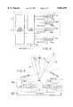
- FIG. 1AA block diagram of a conventional feed-forward cancellation amplifier is illustrated in FIG. 1A.
- an RF input signalwhose spectrum is illustrated in FIG. 1B, is applied to coupler 100a which couples portions of the input signal to delay line 140 and to main amplifier 110.
- Main amplifier 110produces the amplified output whose signal spectrum is illustrated in FIG. 1C.
- the additional spectral components shown in FIG. 1C as compared with FIG. 1Bare the intermodulation products generated due to nonlinearities in main amplifier 110.
- a portion of the amplified output signal spectrum shown in FIG. 1Cis coupled to summer 150 by coupler 100b.
- Delay line 140delays the coupled portion of the input signal with respect to the output of main amplifier 110 producing a delayed signal such that the two signals reach summer 150 at approximately the same time.
- the output of summer 150is an error signal which is coupled to auxiliary amplifier 160.
- Auxiliary amplifier 160adjusts the amplitude of the error signal producing an error correction signal illustrated in FIG. 1D.
- the error correction signalshould be matched in amplitude to the intermodulation products generated by main amplifier 110, but reversed in phase.
- the resultant vector cancellation of the intermodulation productsis performed in coupler 100c where the error correction signal is subtracted from the amplified input signal. For the output signal illustrated in FIG.
- the feed-forward techniquecan be used in an MCPA to effectively suppress intermodulation products but at the cost of low power efficiency and a high demand on complexity and component cost. In particular, high power MCPAs are difficult to master in production.
- phased array antennawhich uses MCPAs in which intermodulation products can be managed without having to resort to expensive and power inefficient feed-forward cancellation techniques.
- the improved MCPAprovides a main amplifier for amplifying an input signal having a plurality of carrier frequencies which produces an amplified output signal comprising the desired signals and additional unwanted frequency components.
- An error signal representative of unwanted frequency components in the amplified output signalis combined with a reference signal to generate a phase shifter input signal which is phase shifted (and/or possibly amplitude varied) in response to a control signal.
- the control signalis updated by comparing the amount of phase shift provided by the phase shifter with a phase offset value.
- the phase offset valuemay be time varying.
- a method of and apparatus for using the improved feed-forward MCPAis employed and described.
- a phased array architectureis presented such that a plurality of radiation lobes are produced.
- the unwanted frequency componentsi.e., intermodulation products
- the main lobethereby providing spatial filtering of the unwanted frequency components.
- FIG. 1Ais a schematic block diagram of a conventional feed-forward cancellation power amplifier
- FIG. 1Billustrates an exemplary signal spectrum for an input signal associated with the block diagram of FIG. 1A;
- FIG. 1Cillustrates an exemplary signal spectrum for an amplified signal associated with the block diagram of FIG. 1A;
- FIG. 1Dillustrates an exemplary signal spectrum for an error signal associated with the block diagram of FIG. 1A
- FIG. 1Eillustrates an exemplary signal spectrum for an output signal associated with the block diagram of FIG. 1A
- FIG. 2Ais a schematic block diagram of feed-forward power amplifier according to a first exemplary embodiment of the present invention
- FIG. 2Billustrates an exemplary signal spectrum for an input signal associated with the block diagram of FIG. 2A
- FIG. 2Cillustrates an exemplary signal spectrum for an amplified signal associated with the block diagram of FIG. 2A;
- FIG. 2Dillustrates an exemplary signal spectrum for an error correction signal associated with the block diagram of FIG. 2A
- FIG. 2Eillustrates an exemplary signal spectrum for an output signal associated with the block diagram of FIG. 2A
- FIG. 2Fis a schematic block diagram of a phase and amplitude modulator advantageously employed as part of the feed-forward power amplifier of the present invention.
- FIG. 3is a schematic block diagram illustrating the operation of a conventional linear phased array antenna
- FIG. 4is a schematic block diagram of a phased array antenna according to a second exemplary embodiment of the present invention.
- FIG. 5is a schematic block diagram illustrating the operation of the phased array antenna of FIG. 4.
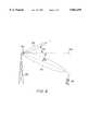
- FIG. 6is an illustration of a phased array antenna according to a second exemplary embodiment of the present invention as used in a cellular base station application.
- FIG. 2AThe block diagram schematic of a feed forward amplifier 200 according to a first exemplary embodiment of the invention is illustrated in FIG. 2A.
- an input signalwhose signal spectrum is illustrated in FIG. 2B, is applied to coupler 220a which couples portions of the input signal to delay line 240 and to main amplifier 230.
- Main amplifier 230produces the amplified output signal spectrum shown in FIG. 2C, a portion of which is coupled to summer 250 by coupler 220b.
- the additional spectral components shown in FIG. 2C as compared with FIG. 2Bare the unwanted intermodulation products generated due to nonlinearities in main amplifier 230.
- Delay line 240delays the coupled portion of the input signal with respect to the amplified output signal from main amplifier 230 producing a delayed signal such that the two signals reach summer 250 at approximately the same time.
- the output of summer 250is an input error signal representative of the unwanted intermodulation products.
- the input error signalis coupled to phase and amplitude modulator 210 which adjusts the phase and amplitude of the input error signal in response to a control signal received from phase control processor 215 (shown in FIG. 2F) producing the error correction signal shown in FIG. 2D.
- the error correction signalis controlled such that the vector addition of the amplified output signal and the error correction signal results in an intermodulation vector of suitable phase and amplitude. This means that the intermodulation products in the output signal (shown in FIG. 2E) have not been reduced to zero (as in FIG. 1E), but rather will remain in the output signal with phase and amplitude which is determined by the phase and amplitude modulator 210.
- This feature of the feed-forward amplifier according to the present inventionallows independent control of the phase and amplitude of the intermodulation products generated by main amplifier 230 which feature may further be advantageously used in a phased array antenna to control the direction of radiation of the intermodulation products independently of the primary radiation lobe as will be described in the ensuing figures and text.
- Synthesizer 216receives a low frequency, e.g. 10 MHz, reference signal from a common reference source (not shown). Synthesizer 216 converts the reference signal to a pilot signal which is close to the frequency of the input signal, but slightly out of band so that the pilot signal will be treated as any other intermodulation product appearing out of band.
- the pilot signal from synthesizer 216is injected into phase shifter 212 by way of coupler 211a where the pilot signal is combined with the output of summer 250 (shown in FIG. 2A) which is the input error signal representative of the unwanted intermodulation products.
- the output of coupler 211ais referred to herein as the phase shifter input signal.
- Phase shifter 212may be any suitable two port network where the phase difference between the output and input signals may be controlled by a control signal (e.g., DC bias).
- phase shifter 212is a loaded line phase shifter, but may also be a switched network, switched line, amplifier type or reflection type network.
- the mechanism of phase shiftis the variance of a small reactance placed across the transmission line.
- a varactor diodewhose capacitance is variable by means of a varying DC bias, may be suitably used for the variable reactance. This arrangement provides for a simple low-cost construction, moderate insertion loss, and is easily controlled for coarse phase adjustments.
- Phase shifter 212shifts the phase of the phase shifter input signal responsive to the control signal received from phase control processor 215.
- the output of phase shifter 212is coupled to amplifier 213.
- the gain of amplifier 213may be variable, but for simplicity is shown as a fixed gain amplifier.
- the amplified output signalis the error correction signal.
- the error correction signalcontains, as a component, the phase shifted version of the pilot signal originally injected at coupler 211a.
- the error correction signalis coupled to coupler 211b which couples a portion of error correction signal to phase detector 214.
- Phase detector 214compares the phase shifted pilot signal received from coupler 211b with the pilot signal received from synthesizer 216 and generates a voltage, V ⁇ n , where the subscript n refers to a particular feed-forward amplifier 200 where there are a plurality of feed-forward amplifiers 200.
- Voltage V ⁇ nwhich is representative of the phase difference between the injected and phase shifted pilot signals, is coupled to phase control processor 215 which compares V ⁇ n , with a reference voltage Vref n (t), which may be time varying.
- Phase control processor 215produces a control signal Vcontrol n (t) which is applied to phase shifter 212 to control the amount of phase shift.
- Vref n (t)By using a time variable reference voltage Vref n (t) it is possible to control the phase shift of phase shifter 212 in accordance with any desired function such as, for example, a random noise function, saw-tooth, or sinusoidal variance with time. In this way, the intermodulation products can be spread out in space (as opposed to being constrained to a single IM lobe) to make the negative IM effects less apparent.
- the choice of Vref n (t)represents a tradeoff between efficiency (i.e., spectrally more efficient to steer all IM products away from desired signal direction) versus reduced complexity (i.e., less effort required to track and control phase if IM products are spread out).
- FIG. 3is a schematic block diagram of a conventional linear phased array antenna.
- a linear arrayincludes a plurality of individual radiating elements 320a-n spaced along a line at a distance d from one another.
- An input signalis coupled through feed network 310 and divided into a plurality of outputs, each output coupled to an individual radiating element 320a-n.
- all of the outputs of the feed network 310are matched in phase and amplitude, but other relationships are possible.
- an amplitude tapercan be applied across the feed network such that end elements receive slightly less power than the center elements of the array thereby improving sidelobe performance.
- the outputs of feed networkare all in-phase and of equal amplitude.
- each radiating element 320a-nAt the base of each radiating element 320a-n is a phase shifting and amplitude varying device 330a-n, respectively, which controls the relative amplitude and phase fed to each radiating element 320a-n.
- the set of coefficients a nis referred to as the array-amplitude taper, while the ⁇ n parameters are referred to as the phase taper.
- the ⁇ n parametersare referred to as the phase taper.
- ⁇ nillustrates that to produce a maximum value for the radiated field in the direction of the scan angle ⁇ 0 the phase taper across the array is a linear taper.
- a linear taperis one in which there is a constant phase difference between adjacent radiating elements 320a-n.
- an antenna 400according to a second exemplary embodiment of the present invention is illustrated in which the feed-forward amplifier described hereinabove may be advantageously employed.
- an input signalis coupled to feed network 310 which divides the input signal into a plurality of outputs.
- the plurality of outputs of feed network 310is each coupled to feed forward amplifiers 200a-n previously described hereinabove.
- the output of each feed forward amplifier 200a-nis coupled to a radiating element 330a-n respectively.
- Control signals to each feed-forward amplifier 200a-nare provided by beam steering controller 410.
- the operation of antenna 400may be explained with the assistance of the schematic block diagram illustrated in FIG. 5 where for simplicity the number of antenna elements 320a-n has been restricted to two.
- each feed forward amplifier 200a-ncan be viewed as producing two separate signals: one of which is the desired signal whose phase and amplitude is modified according to a n e j ⁇ n and the undesired IM signal whose phase and amplitude is modified according to b n e j ⁇ n.
- no amplitude taperis used and the amplitude coefficients a n and b n are set equal to unity.
- a first phase taperis applied to the ⁇ n parameters resulting in a first beam 510 comprising the desired signal(s) being radiated in the direction of scan angle ⁇ 0 .
- a second phase taperis applied to the ⁇ n parameters resulting in a second beam 520 comprising the unwanted signals being radiated in the direction of scan angle ⁇ 0 .
- Sidelobes of the second beam 520will be present in the direction of the first beam 510, but at a sufficiently low level so as not to present an interference problem in the direction of the first beam 510.
- FIG. 6illustrates an example of how array antenna 400 may be employed in an exemplary radio communication system.
- Antenna 400is mounted on a mast tower 600, the top of building, or any other suitable location which elevates antenna 400 a suitable distance above the ground and which provides a clear line of sight communication path between mobile station(s) 610 operating within the vicinity of the base station and the base station antenna 400.
- a plurality of radiation patterns 510 and 520are produced by antenna 400. For simplicity, only two patterns will be discussed: one in which the desired downlink signals are radiated which will be referred to as the primary radiation pattern, or primary lobe 510; and one in which unwanted intermodulation products are radiated which will be referred to as the intermodulation (IM) radiation pattern, or IM lobe 520.
- IMintermodulation
- Primary lobe 510is angled downward from a plane 530 parallel with the surface of the earth either by physically pointing antenna 400 downwards, or alternatively by providing a linear phase taper across the outputs of feed network 310.
- IM lobe 520which contains the unwanted intermodulation products, is oriented upwards and away from the primary lobe 510 by applying the appropriate phase taper to the error correction signals generated in each feed forward amplifier 200a-n.
- the IM lobe 520may be advantageously spatially spread by applying a time varying phase offset control signal to amplifiers 200a-n.
- the time variationmay be in the form of a saw-tooth wave to "sweep" the IM beam across a wide scan angle, or a noise related variation may be used to "spread" the IM beam across a wide scan angle.
- a number of relatively small amplifierscan be used in place of a single large amplifier. These smaller amplifiers are, typically, more power efficient than the larger ones used conventionally in SCPA applications. Cable losses after the amplifying stage are substantially reduced, since the smaller amplifiers are mounted on the antenna array.
- the DC to RF power conversion efficiency according to exemplary embodiments of the present inventionwill typically be about the same as that associated with the SCPA antenna/combiner method, but with the advantage that the antenna sizes are independent of the number of transmitted carriers.
Landscapes
- Physics & Mathematics (AREA)
- Nonlinear Science (AREA)
- Engineering & Computer Science (AREA)
- Power Engineering (AREA)
- Variable-Direction Aerials And Aerial Arrays (AREA)
- Amplifiers (AREA)
- Mobile Radio Communication Systems (AREA)
Abstract
Description
Ψ.sub.n =-nkdsin θ.sub.0
Claims (14)
Priority Applications (12)
| Application Number | Priority Date | Filing Date | Title |
|---|---|---|---|
| US08/697,279US5862459A (en) | 1996-08-27 | 1996-08-27 | Method of and apparatus for filtering intermodulation products in a radiocommunication system |
| KR10-1999-7001621AKR100459617B1 (en) | 1996-08-27 | 1997-08-26 | Method of and apparatus for filtering intermodulation products in a radiocommunication system |
| CN97198815ACN1113455C (en) | 1996-08-27 | 1997-08-26 | Method of and apparatus for filtering intermodulation products in a radiocommunication system |
| GB9904271AGB2332316B (en) | 1996-08-27 | 1997-08-26 | Method of and apparatus for filtering intermodulation products in a radiocommunication system |
| JP51155698AJP4027427B2 (en) | 1996-08-27 | 1997-08-26 | Method and apparatus for filtering intermodulation components in a wireless communication system |
| PCT/SE1997/001410WO1998009372A1 (en) | 1996-08-27 | 1997-08-26 | Method of and apparatus for filtering intermodulation products in a radiocommunication system |
| DE19781955TDE19781955T1 (en) | 1996-08-27 | 1997-08-26 | Method and device for filtering intermodulation products in a radio communication system |
| TW086112220ATW349298B (en) | 1996-08-27 | 1997-08-26 | Method of and apparatus for filtering intermodulation products in a radiocommunication system |
| GB0103848AGB2356308B (en) | 1996-08-27 | 1997-08-26 | Method of and apparatus for filtering intermodulation products in a radiocommunication system |
| AU38771/97AAU3877197A (en) | 1996-08-27 | 1997-08-26 | Method of and apparatus for filtering intermodulation products in a radiocommunication system |
| DE19781955ADE19781955B4 (en) | 1996-08-27 | 1997-08-26 | A feed-forward multi-carrier power amplifier and method for controlling the amplitude and phase of intermodulation products in a multi-carrier power amplifier |
| SE9900650ASE521066C2 (en) | 1996-08-27 | 1999-02-24 | Feedforward multi-carrier power amplifier for cellular radio communications |
Applications Claiming Priority (1)
| Application Number | Priority Date | Filing Date | Title |
|---|---|---|---|
| US08/697,279US5862459A (en) | 1996-08-27 | 1996-08-27 | Method of and apparatus for filtering intermodulation products in a radiocommunication system |
Publications (1)
| Publication Number | Publication Date |
|---|---|
| US5862459Atrue US5862459A (en) | 1999-01-19 |
Family
ID=24800521
Family Applications (1)
| Application Number | Title | Priority Date | Filing Date |
|---|---|---|---|
| US08/697,279Expired - LifetimeUS5862459A (en) | 1996-08-27 | 1996-08-27 | Method of and apparatus for filtering intermodulation products in a radiocommunication system |
Country Status (9)
| Country | Link |
|---|---|
| US (1) | US5862459A (en) |
| JP (1) | JP4027427B2 (en) |
| KR (1) | KR100459617B1 (en) |
| CN (1) | CN1113455C (en) |
| AU (1) | AU3877197A (en) |
| DE (2) | DE19781955T1 (en) |
| GB (1) | GB2332316B (en) |
| TW (1) | TW349298B (en) |
| WO (1) | WO1998009372A1 (en) |
Cited By (43)
| Publication number | Priority date | Publication date | Assignee | Title |
|---|---|---|---|---|
| US6208207B1 (en) | 1999-05-05 | 2001-03-27 | Simon Fraser University | Adaptive linearizer for RF power amplifiers |
| US6330289B1 (en)* | 1998-10-16 | 2001-12-11 | Nortel Networks Limited | System for improving base station amplifier performance |
| US6334058B1 (en)* | 1997-08-28 | 2001-12-25 | Telefonaktiebolaget Lm Ericsson (Publ) | Method and apparatus for radio power allocation to a channel during channel assignment based on current system conditions |
| EP1170860A1 (en)* | 2000-06-27 | 2002-01-09 | Nortel Matra Cellular | Improved multi-carrier receiver for radio telecommunications network |
| US6339712B1 (en)* | 1998-07-27 | 2002-01-15 | Telefonaktiebolaget Lm Ericsson (Publ). | Method and device for radio communication |
| US6362787B1 (en) | 1999-04-26 | 2002-03-26 | Andrew Corporation | Lightning protection for an active antenna using patch/microstrip elements |
| US20020048326A1 (en)* | 2000-08-29 | 2002-04-25 | Sahlman Karl-Gosta Emanuel | Method and apparatus for plurality signal generation |
| US6448930B1 (en) | 1999-10-15 | 2002-09-10 | Andrew Corporation | Indoor antenna |
| US20020146996A1 (en)* | 2001-03-06 | 2002-10-10 | Bachman Thomas A. | Scanning receiver for use in power amplifier linearization |
| EP1152523A4 (en)* | 1999-09-17 | 2002-10-23 | Ntt Docomo Inc | Feedforward multi-terminal power-synthesizing power amplifier |
| US6553211B1 (en)* | 1998-08-20 | 2003-04-22 | Lucent Technologies Inc. | Method and apparatus for adjusting pilot signal relative to input signal |
| US20030100039A1 (en)* | 2000-04-29 | 2003-05-29 | Duecker Klaus | Novel human phospholipase c delta 5 |
| US6584330B1 (en) | 2000-07-18 | 2003-06-24 | Telefonaktiebolaget Lm Ericsson (Publ) | Adaptive power management for a node of a cellular telecommunications network |
| US6583763B2 (en) | 1999-04-26 | 2003-06-24 | Andrew Corporation | Antenna structure and installation |
| US6621469B2 (en) | 1999-04-26 | 2003-09-16 | Andrew Corporation | Transmit/receive distributed antenna systems |
| US6683495B2 (en) | 2001-06-28 | 2004-01-27 | Simon Fraser University | Reduced architecture for multibranch feedforward power amplifier linearizers |
| US6701137B1 (en) | 1999-04-26 | 2004-03-02 | Andrew Corporation | Antenna system architecture |
| US20040066352A1 (en)* | 2002-09-27 | 2004-04-08 | Andrew Corporation | Multicarrier distributed active antenna |
| US6734731B2 (en) | 2001-06-28 | 2004-05-11 | Simon Fraser University | Self-calibrated power amplifier linearizers |
| US6744312B2 (en) | 2001-03-06 | 2004-06-01 | Andrew Corporation | Adaptive power amplifier system |
| US20040136470A1 (en)* | 2003-01-15 | 2004-07-15 | Andrew Corporation | Uncorrelated adaptive predistorter |
| US20040161053A1 (en)* | 2001-06-28 | 2004-08-19 | Simon Fraser University | Decorrelated power amplifier linearizers |
| GB2387274B (en)* | 2000-11-01 | 2004-09-01 | Andrew Corp | Distributed antenna systems |
| US6792251B2 (en)* | 1998-07-10 | 2004-09-14 | Telefonaktiebolaget Lm Ericsson (Publ) | Arrangement and method for improving multi-carrier power amplifier efficiency |
| US20040192392A1 (en)* | 2002-09-18 | 2004-09-30 | Andrew Corporation | Distributed active transmit and/or receive antenna |
| US20040192233A1 (en)* | 2002-04-18 | 2004-09-30 | Motorola, Inc. | Redundant linear power amplifier system |
| US20040198414A1 (en)* | 2002-03-19 | 2004-10-07 | Hunton Matthew J. | System and method for eliminating signal zero crossings in single and multiple channel communication systems |
| US20040203804A1 (en)* | 2003-01-03 | 2004-10-14 | Andrew Corporation | Reduction of intermodualtion product interference in a network having sectorized access points |
| US20040204109A1 (en)* | 2002-09-30 | 2004-10-14 | Andrew Corporation | Active array antenna and system for beamforming |
| US6812905B2 (en) | 1999-04-26 | 2004-11-02 | Andrew Corporation | Integrated active antenna for multi-carrier applications |
| US20040227570A1 (en)* | 2003-05-12 | 2004-11-18 | Andrew Corporation | Optimization of error loops in distributed power amplifiers |
| US6829471B2 (en) | 2001-03-07 | 2004-12-07 | Andrew Corporation | Digital baseband receiver in a multi-carrier power amplifier |
| US6844863B2 (en) | 2002-09-27 | 2005-01-18 | Andrew Corporation | Active antenna with interleaved arrays of antenna elements |
| US20050017801A1 (en)* | 2003-07-23 | 2005-01-27 | Andrew Corporation | Elimination of peak clipping and improved efficiency for RF power amplifiers with a predistorter |
| US20050024138A1 (en)* | 2003-07-31 | 2005-02-03 | Andrew Corporation | Predistorter for phase modulated signals with low peak to average ratios |
| US20050073360A1 (en)* | 2003-10-06 | 2005-04-07 | Andrew Corporation | Architecture and implementation methods of digital predistortion circuitry |
| US20050170794A1 (en)* | 2004-01-30 | 2005-08-04 | Eero Koukkari | Adjusting circuit |
| US20070188379A1 (en)* | 2006-02-14 | 2007-08-16 | The Aerospace Corporation | Higher-order intermodulation reduction using phase and angle smearing |
| US7623868B2 (en) | 2002-09-16 | 2009-11-24 | Andrew Llc | Multi-band wireless access point comprising coextensive coverage regions |
| EP2178206A2 (en) | 2008-10-17 | 2010-04-21 | Fraunhofer-Gesellschaft zur Förderung der angewandten Forschung e.V. | Feed-forward amplifier with device for creating a correction signal |
| US7729668B2 (en) | 2003-04-03 | 2010-06-01 | Andrew Llc | Independence between paths that predistort for memory and memory-less distortion in power amplifiers |
| US8010042B2 (en) | 1999-07-20 | 2011-08-30 | Andrew Llc | Repeaters for wireless communication systems |
| US20130099973A1 (en)* | 2011-10-21 | 2013-04-25 | Electronics And Telecommunications Research Institute | Random jitter beamforming method and transmitter and receiver using the same |
Families Citing this family (7)
| Publication number | Priority date | Publication date | Assignee | Title |
|---|---|---|---|---|
| US6704557B1 (en)* | 1999-04-22 | 2004-03-09 | Lucent Technologies Inc. | System and method for protecting a receiver from jamming interference |
| KR100758309B1 (en)* | 2006-09-29 | 2007-09-12 | 한국전자통신연구원 | RF Path Error Correction Device and Method for Wireless Communication System with Multiple Antennas |
| CN101656512B (en)* | 2008-08-18 | 2012-06-27 | 富士通株式会社 | Device and method for measuring nonlinearity of power amplifier and predistortion compensation device |
| CN103891228B (en)* | 2013-12-30 | 2016-12-14 | 华为技术有限公司 | Disturbance restraining method and device |
| US9356632B2 (en)* | 2014-10-07 | 2016-05-31 | Qualcomm Incorporated | Intermodulation distortion canceller for use in multi-carrier transmitters |
| WO2018150454A1 (en)* | 2017-02-14 | 2018-08-23 | 三菱電機株式会社 | Feed-forward amplifier and antenna device |
| WO2020246000A1 (en)* | 2019-06-06 | 2020-12-10 | 三菱電機株式会社 | Signal processing device and radar device |
Citations (9)
| Publication number | Priority date | Publication date | Assignee | Title |
|---|---|---|---|---|
| US4389618A (en)* | 1981-04-15 | 1983-06-21 | The United States Of America As Represented By The Secretary Of The Navy | Adaptive feed-forward system |
| US4554514A (en)* | 1984-12-21 | 1985-11-19 | Rca Corporation | Predistortion circuit with feedback |
| US4560945A (en)* | 1984-09-04 | 1985-12-24 | Westinghouse Electric Corp. | Adaptive feedforward cancellation technique that is effective in reducing amplifier harmonic distortion products as well as intermodulation distortion products |
| US4885551A (en)* | 1988-10-31 | 1989-12-05 | American Telephone And Telegraph Company At&T Bell Laboratories | Feed forward linear amplifier |
| WO1991016760A1 (en)* | 1990-04-25 | 1991-10-31 | British Technology Group Ltd | Apparatus and method for reducing distortion in amplification |
| WO1994009568A1 (en)* | 1992-10-09 | 1994-04-28 | E-Systems, Inc. | Adaptive co-channel interference reduction system for cellular telephone central base stations |
| EP0595247A1 (en)* | 1992-10-28 | 1994-05-04 | Atr Optical And Radio Communications Research Laboratories | Apparatus for controlling array antenna comprising a plurality of antenna elements and method therefor |
| WO1994017587A1 (en)* | 1993-01-28 | 1994-08-04 | Telefonaktiebolaget Lm Ericsson | Linear amplifier control |
| GB2296615A (en)* | 1994-12-21 | 1996-07-03 | Univ Bristol | Distortion and noise reduction in wide band feedforward amplifier/mixer |
Family Cites Families (2)
| Publication number | Priority date | Publication date | Assignee | Title |
|---|---|---|---|---|
| US6549242B1 (en)* | 1997-04-04 | 2003-04-15 | Harris Corporation | Combining adjacent TV channels for transmission by a common antenna |
| KR19980085583A (en)* | 1997-05-29 | 1998-12-05 | 이형도 | Stabilization Circuit of Power Amplifier for Mobile Phone |
- 1996
- 1996-08-27USUS08/697,279patent/US5862459A/ennot_activeExpired - Lifetime
- 1997
- 1997-08-26JPJP51155698Apatent/JP4027427B2/ennot_activeExpired - Fee Related
- 1997-08-26TWTW086112220Apatent/TW349298B/ennot_activeIP Right Cessation
- 1997-08-26CNCN97198815Apatent/CN1113455C/ennot_activeExpired - Lifetime
- 1997-08-26WOPCT/SE1997/001410patent/WO1998009372A1/enactiveIP Right Grant
- 1997-08-26DEDE19781955Tpatent/DE19781955T1/enactivePending
- 1997-08-26DEDE19781955Apatent/DE19781955B4/ennot_activeExpired - Lifetime
- 1997-08-26GBGB9904271Apatent/GB2332316B/ennot_activeExpired - Lifetime
- 1997-08-26KRKR10-1999-7001621Apatent/KR100459617B1/ennot_activeExpired - Fee Related
- 1997-08-26AUAU38771/97Apatent/AU3877197A/ennot_activeAbandoned
Patent Citations (9)
| Publication number | Priority date | Publication date | Assignee | Title |
|---|---|---|---|---|
| US4389618A (en)* | 1981-04-15 | 1983-06-21 | The United States Of America As Represented By The Secretary Of The Navy | Adaptive feed-forward system |
| US4560945A (en)* | 1984-09-04 | 1985-12-24 | Westinghouse Electric Corp. | Adaptive feedforward cancellation technique that is effective in reducing amplifier harmonic distortion products as well as intermodulation distortion products |
| US4554514A (en)* | 1984-12-21 | 1985-11-19 | Rca Corporation | Predistortion circuit with feedback |
| US4885551A (en)* | 1988-10-31 | 1989-12-05 | American Telephone And Telegraph Company At&T Bell Laboratories | Feed forward linear amplifier |
| WO1991016760A1 (en)* | 1990-04-25 | 1991-10-31 | British Technology Group Ltd | Apparatus and method for reducing distortion in amplification |
| WO1994009568A1 (en)* | 1992-10-09 | 1994-04-28 | E-Systems, Inc. | Adaptive co-channel interference reduction system for cellular telephone central base stations |
| EP0595247A1 (en)* | 1992-10-28 | 1994-05-04 | Atr Optical And Radio Communications Research Laboratories | Apparatus for controlling array antenna comprising a plurality of antenna elements and method therefor |
| WO1994017587A1 (en)* | 1993-01-28 | 1994-08-04 | Telefonaktiebolaget Lm Ericsson | Linear amplifier control |
| GB2296615A (en)* | 1994-12-21 | 1996-07-03 | Univ Bristol | Distortion and noise reduction in wide band feedforward amplifier/mixer |
Cited By (79)
| Publication number | Priority date | Publication date | Assignee | Title |
|---|---|---|---|---|
| US6334058B1 (en)* | 1997-08-28 | 2001-12-25 | Telefonaktiebolaget Lm Ericsson (Publ) | Method and apparatus for radio power allocation to a channel during channel assignment based on current system conditions |
| US6792251B2 (en)* | 1998-07-10 | 2004-09-14 | Telefonaktiebolaget Lm Ericsson (Publ) | Arrangement and method for improving multi-carrier power amplifier efficiency |
| US6339712B1 (en)* | 1998-07-27 | 2002-01-15 | Telefonaktiebolaget Lm Ericsson (Publ). | Method and device for radio communication |
| US6553211B1 (en)* | 1998-08-20 | 2003-04-22 | Lucent Technologies Inc. | Method and apparatus for adjusting pilot signal relative to input signal |
| US6330289B1 (en)* | 1998-10-16 | 2001-12-11 | Nortel Networks Limited | System for improving base station amplifier performance |
| US6621469B2 (en) | 1999-04-26 | 2003-09-16 | Andrew Corporation | Transmit/receive distributed antenna systems |
| US7053838B2 (en) | 1999-04-26 | 2006-05-30 | Andrew Corporation | Antenna structure and installation |
| US6362787B1 (en) | 1999-04-26 | 2002-03-26 | Andrew Corporation | Lightning protection for an active antenna using patch/microstrip elements |
| US6701137B1 (en) | 1999-04-26 | 2004-03-02 | Andrew Corporation | Antenna system architecture |
| US6812905B2 (en) | 1999-04-26 | 2004-11-02 | Andrew Corporation | Integrated active antenna for multi-carrier applications |
| US6690328B2 (en) | 1999-04-26 | 2004-02-10 | Andrew Corporation | Antenna structure and installation |
| US6597325B2 (en) | 1999-04-26 | 2003-07-22 | Andrew Corporation | Transmit/receive distributed antenna systems |
| US20050099359A1 (en)* | 1999-04-26 | 2005-05-12 | Andrew Corporation | Antenna structure and installation |
| US6583763B2 (en) | 1999-04-26 | 2003-06-24 | Andrew Corporation | Antenna structure and installation |
| US20040169558A1 (en)* | 1999-05-05 | 2004-09-02 | Cavers James K. | Adaptive linearizer for RF power amplifiers |
| US6208207B1 (en) | 1999-05-05 | 2001-03-27 | Simon Fraser University | Adaptive linearizer for RF power amplifiers |
| US6897722B2 (en) | 1999-05-05 | 2005-05-24 | Andrew Corporation | Adaptive linearizer for RF power amplifiers |
| US6414546B2 (en) | 1999-05-05 | 2002-07-02 | Simon Fraser University | Adaptive linearizer for RFpower amplifiers |
| US6734732B2 (en) | 1999-05-05 | 2004-05-11 | James K. Cavers | Adaptive linearizer for RF power amplifiers |
| US8010042B2 (en) | 1999-07-20 | 2011-08-30 | Andrew Llc | Repeaters for wireless communication systems |
| US8358970B2 (en) | 1999-07-20 | 2013-01-22 | Andrew Corporation | Repeaters for wireless communication systems |
| US8971796B2 (en) | 1999-07-20 | 2015-03-03 | Andrew Llc | Repeaters for wireless communication systems |
| US8630581B2 (en) | 1999-07-20 | 2014-01-14 | Andrew Llc | Repeaters for wireless communication systems |
| EP1152523A4 (en)* | 1999-09-17 | 2002-10-23 | Ntt Docomo Inc | Feedforward multi-terminal power-synthesizing power amplifier |
| US6448930B1 (en) | 1999-10-15 | 2002-09-10 | Andrew Corporation | Indoor antenna |
| US20030100039A1 (en)* | 2000-04-29 | 2003-05-29 | Duecker Klaus | Novel human phospholipase c delta 5 |
| WO2002001748A3 (en)* | 2000-06-27 | 2002-06-06 | Nortel Networks Ltd | Improved multi-carrier receiver for a radio telecommunications network |
| US20030162520A1 (en)* | 2000-06-27 | 2003-08-28 | Calmel Pierre Emmanuel | Improved multi-carrier receiver for a radio telecommunication network |
| EP1170860A1 (en)* | 2000-06-27 | 2002-01-09 | Nortel Matra Cellular | Improved multi-carrier receiver for radio telecommunications network |
| US6584330B1 (en) | 2000-07-18 | 2003-06-24 | Telefonaktiebolaget Lm Ericsson (Publ) | Adaptive power management for a node of a cellular telecommunications network |
| US20020048326A1 (en)* | 2000-08-29 | 2002-04-25 | Sahlman Karl-Gosta Emanuel | Method and apparatus for plurality signal generation |
| US6934341B2 (en) | 2000-08-29 | 2005-08-23 | Telefonaktiebolaget Lm Ericsson (Publ) | Method and apparatus for plurality signal generation |
| GB2387274B (en)* | 2000-11-01 | 2004-09-01 | Andrew Corp | Distributed antenna systems |
| US20020146996A1 (en)* | 2001-03-06 | 2002-10-10 | Bachman Thomas A. | Scanning receiver for use in power amplifier linearization |
| US6744312B2 (en) | 2001-03-06 | 2004-06-01 | Andrew Corporation | Adaptive power amplifier system |
| US7167693B2 (en) | 2001-03-06 | 2007-01-23 | Andrew Corporation | Scanning receiver for use in power amplifier linearization |
| US20050032485A1 (en)* | 2001-03-06 | 2005-02-10 | Andrew Corporation | Scanning receiver for use in power amplifier linearization |
| US6829471B2 (en) | 2001-03-07 | 2004-12-07 | Andrew Corporation | Digital baseband receiver in a multi-carrier power amplifier |
| US7015751B2 (en) | 2001-06-28 | 2006-03-21 | Simon Fraser University | Decorrelated power amplifier linearizers |
| US7084703B2 (en) | 2001-06-28 | 2006-08-01 | Andrew Corporation | Self-calibrated power amplifier linearizers |
| US6683495B2 (en) | 2001-06-28 | 2004-01-27 | Simon Fraser University | Reduced architecture for multibranch feedforward power amplifier linearizers |
| US6831512B2 (en) | 2001-06-28 | 2004-12-14 | Simon Fraser University | Self-calibrated power amplifier linearizers |
| US6734731B2 (en) | 2001-06-28 | 2004-05-11 | Simon Fraser University | Self-calibrated power amplifier linearizers |
| US20040108898A1 (en)* | 2001-06-28 | 2004-06-10 | Simon Fraser University | Reduced architecture for multibranch feedforward power amplifier linearizers |
| US7187234B2 (en) | 2001-06-28 | 2007-03-06 | Andrew Corporation | Decorrelated power amplifier linearizers |
| US20040161053A1 (en)* | 2001-06-28 | 2004-08-19 | Simon Fraser University | Decorrelated power amplifier linearizers |
| US20040160273A1 (en)* | 2001-06-28 | 2004-08-19 | Simon Fraser University | Self-calibrated power amplifier linearizers |
| US20050116776A1 (en)* | 2001-06-28 | 2005-06-02 | Cavers James K. | Self-calibrated power amplifier linearizers |
| US20040198414A1 (en)* | 2002-03-19 | 2004-10-07 | Hunton Matthew J. | System and method for eliminating signal zero crossings in single and multiple channel communication systems |
| US20040192233A1 (en)* | 2002-04-18 | 2004-09-30 | Motorola, Inc. | Redundant linear power amplifier system |
| US7623868B2 (en) | 2002-09-16 | 2009-11-24 | Andrew Llc | Multi-band wireless access point comprising coextensive coverage regions |
| US20040192392A1 (en)* | 2002-09-18 | 2004-09-30 | Andrew Corporation | Distributed active transmit and/or receive antenna |
| US6983174B2 (en) | 2002-09-18 | 2006-01-03 | Andrew Corporation | Distributed active transmit and/or receive antenna |
| US20040066352A1 (en)* | 2002-09-27 | 2004-04-08 | Andrew Corporation | Multicarrier distributed active antenna |
| US6844863B2 (en) | 2002-09-27 | 2005-01-18 | Andrew Corporation | Active antenna with interleaved arrays of antenna elements |
| US6906681B2 (en) | 2002-09-27 | 2005-06-14 | Andrew Corporation | Multicarrier distributed active antenna |
| US7280848B2 (en) | 2002-09-30 | 2007-10-09 | Andrew Corporation | Active array antenna and system for beamforming |
| US20040204109A1 (en)* | 2002-09-30 | 2004-10-14 | Andrew Corporation | Active array antenna and system for beamforming |
| US20040203804A1 (en)* | 2003-01-03 | 2004-10-14 | Andrew Corporation | Reduction of intermodualtion product interference in a network having sectorized access points |
| US20040136470A1 (en)* | 2003-01-15 | 2004-07-15 | Andrew Corporation | Uncorrelated adaptive predistorter |
| US7403573B2 (en) | 2003-01-15 | 2008-07-22 | Andrew Corporation | Uncorrelated adaptive predistorter |
| US7729668B2 (en) | 2003-04-03 | 2010-06-01 | Andrew Llc | Independence between paths that predistort for memory and memory-less distortion in power amplifiers |
| US6972622B2 (en) | 2003-05-12 | 2005-12-06 | Andrew Corporation | Optimization of error loops in distributed power amplifiers |
| US20040227570A1 (en)* | 2003-05-12 | 2004-11-18 | Andrew Corporation | Optimization of error loops in distributed power amplifiers |
| US7259630B2 (en) | 2003-07-23 | 2007-08-21 | Andrew Corporation | Elimination of peak clipping and improved efficiency for RF power amplifiers with a predistorter |
| US20050017801A1 (en)* | 2003-07-23 | 2005-01-27 | Andrew Corporation | Elimination of peak clipping and improved efficiency for RF power amplifiers with a predistorter |
| US20050024138A1 (en)* | 2003-07-31 | 2005-02-03 | Andrew Corporation | Predistorter for phase modulated signals with low peak to average ratios |
| US6963242B2 (en) | 2003-07-31 | 2005-11-08 | Andrew Corporation | Predistorter for phase modulated signals with low peak to average ratios |
| US7023273B2 (en) | 2003-10-06 | 2006-04-04 | Andrew Corporation | Architecture and implementation methods of digital predistortion circuitry |
| US20050073360A1 (en)* | 2003-10-06 | 2005-04-07 | Andrew Corporation | Architecture and implementation methods of digital predistortion circuitry |
| US20050170794A1 (en)* | 2004-01-30 | 2005-08-04 | Eero Koukkari | Adjusting circuit |
| US20070188379A1 (en)* | 2006-02-14 | 2007-08-16 | The Aerospace Corporation | Higher-order intermodulation reduction using phase and angle smearing |
| US7420508B2 (en) | 2006-02-14 | 2008-09-02 | The Aerospace Corporation | Higher-order intermodulation reduction using phase and angle smearing |
| US7940106B2 (en) | 2008-10-17 | 2011-05-10 | Fraunhofer-Gesellschaft Zur Foerderung Der Angewandten Forschung E.V. | Apparatus for generating a correction signal |
| DE102008052172A1 (en) | 2008-10-17 | 2010-04-22 | Fraunhofer-Gesellschaft zur Förderung der angewandten Forschung e.V. | Device for generating a correction signal |
| US20100097134A1 (en)* | 2008-10-17 | 2010-04-22 | Fraunhofer-Gesellschaft Zur Forderung Der Angewandten Forschung E.V. | Apparatus for generating a correction signal |
| EP2178206A2 (en) | 2008-10-17 | 2010-04-21 | Fraunhofer-Gesellschaft zur Förderung der angewandten Forschung e.V. | Feed-forward amplifier with device for creating a correction signal |
| US20130099973A1 (en)* | 2011-10-21 | 2013-04-25 | Electronics And Telecommunications Research Institute | Random jitter beamforming method and transmitter and receiver using the same |
| US9270023B2 (en)* | 2011-10-21 | 2016-02-23 | Electronics And Telecommunications Research Institute | Random jitter beamforming method and transmitter and receiver using the same |
Also Published As
| Publication number | Publication date |
|---|---|
| AU3877197A (en) | 1998-03-19 |
| JP4027427B2 (en) | 2007-12-26 |
| GB2332316B (en) | 2001-04-11 |
| TW349298B (en) | 1999-01-01 |
| WO1998009372A1 (en) | 1998-03-05 |
| GB2332316A (en) | 1999-06-16 |
| DE19781955B4 (en) | 2011-11-24 |
| DE19781955T1 (en) | 1999-09-09 |
| JP2000517134A (en) | 2000-12-19 |
| KR100459617B1 (en) | 2004-12-03 |
| CN1233358A (en) | 1999-10-27 |
| GB9904271D0 (en) | 1999-04-21 |
| KR20000035900A (en) | 2000-06-26 |
| CN1113455C (en) | 2003-07-02 |
Similar Documents
| Publication | Publication Date | Title |
|---|---|---|
| US5862459A (en) | Method of and apparatus for filtering intermodulation products in a radiocommunication system | |
| US5396256A (en) | Apparatus for controlling array antenna comprising a plurality of antenna elements and method therefor | |
| US5463357A (en) | Wide-band microwave modulator arrangements | |
| US7433713B2 (en) | Mobile radio base station | |
| US6181920B1 (en) | Transmitter that selectively polarizes a radio wave | |
| US5025485A (en) | Multi-feed, multi-channel communication system | |
| WO2016167145A1 (en) | Phased array antenna device | |
| US6642883B2 (en) | Multi-beam antenna with interference cancellation network | |
| KR20000077161A (en) | Antenna array system having coherent and noncoherent reception characteristics | |
| Cai et al. | Beamforming codebook compensation for beam squint with channel capacity constraint | |
| US9137067B1 (en) | High efficiency outphasing transmitter for electronically scanned arrays | |
| US7558541B2 (en) | Amplifier gain and phase stabilizer | |
| US10630460B2 (en) | Microwave communication apparatus with multi-channel radio frequency module and continuous beam scanning and method for electronic beam scanning | |
| CN108809427B (en) | Wave beam adjustable terahertz wireless communication system and communication method based on optical phase control | |
| US5555016A (en) | Video signal distribution system | |
| US6392481B1 (en) | Method and apparatus for improved fed forward amplification | |
| GB2356308A (en) | Feed-forward distortion reduction with unwanted components being radiated away from phased array | |
| JP6219007B1 (en) | Feed forward amplifier and antenna device | |
| JP3634047B2 (en) | Grating lobe cancel antenna for mobile SNG | |
| US11177840B1 (en) | Smart multiband antenna system | |
| US20070013444A1 (en) | Parallel path pre-distorted amplifier | |
| WO1999021292A2 (en) | Method and arrangement in a telecommunication system | |
| JP2003142923A (en) | Phased array antenna | |
| EP0633697A1 (en) | Video signal distribution system | |
| JPH04110684A (en) | Radar device |
Legal Events
| Date | Code | Title | Description |
|---|---|---|---|
| AS | Assignment | Owner name:TELEFONAKTIEBOLAGET LM ERICSSON, SWEDEN Free format text:ASSIGNMENT OF ASSIGNORS INTEREST;ASSIGNOR:CHARAS, PHILIPPE;REEL/FRAME:008135/0660 Effective date:19960826 | |
| STCF | Information on status: patent grant | Free format text:PATENTED CASE | |
| FPAY | Fee payment | Year of fee payment:4 | |
| REMI | Maintenance fee reminder mailed | ||
| FPAY | Fee payment | Year of fee payment:8 | |
| FPAY | Fee payment | Year of fee payment:12 | |
| AS | Assignment | Owner name:CLUSTER LLC, DELAWARE Free format text:ASSIGNMENT OF ASSIGNORS INTEREST;ASSIGNOR:TELEFONAKTIEBOLAGET L M ERICSSON (PUBL);REEL/FRAME:030201/0186 Effective date:20130211 | |
| AS | Assignment | Owner name:UNWIRED PLANET, LLC, NEVADA Free format text:ASSIGNMENT OF ASSIGNORS INTEREST;ASSIGNOR:CLUSTER LLC;REEL/FRAME:030219/0001 Effective date:20130213 | |
| AS | Assignment | Owner name:CLUSTER LLC, SWEDEN Free format text:NOTICE OF GRANT OF SECURITY INTEREST IN PATENTS;ASSIGNOR:UNWIRED PLANET, LLC;REEL/FRAME:030369/0601 Effective date:20130213 |