US5862003A - Micromotion amplifier - Google Patents
Micromotion amplifierDownload PDFInfo
- Publication number
- US5862003A US5862003AUS08/667,880US66788096AUS5862003AUS 5862003 AUS5862003 AUS 5862003AUS 66788096 AUS66788096 AUS 66788096AUS 5862003 AUS5862003 AUS 5862003A
- Authority
- US
- United States
- Prior art keywords
- motion
- actuator
- beams
- amplifier
- stage
- Prior art date
- Legal status (The legal status is an assumption and is not a legal conclusion. Google has not performed a legal analysis and makes no representation as to the accuracy of the status listed.)
- Expired - Lifetime
Links
Images


Classifications
- H—ELECTRICITY
- H02—GENERATION; CONVERSION OR DISTRIBUTION OF ELECTRIC POWER
- H02N—ELECTRIC MACHINES NOT OTHERWISE PROVIDED FOR
- H02N1/00—Electrostatic generators or motors using a solid moving electrostatic charge carrier
- H02N1/002—Electrostatic motors
- H02N1/006—Electrostatic motors of the gap-closing type
- H02N1/008—Laterally driven motors, e.g. of the comb-drive type
- B—PERFORMING OPERATIONS; TRANSPORTING
- B81—MICROSTRUCTURAL TECHNOLOGY
- B81B—MICROSTRUCTURAL DEVICES OR SYSTEMS, e.g. MICROMECHANICAL DEVICES
- B81B3/00—Devices comprising flexible or deformable elements, e.g. comprising elastic tongues or membranes
- B81B3/0035—Constitution or structural means for controlling the movement of the flexible or deformable elements
- B81B3/0037—For increasing stroke, i.e. achieve large displacement of actuated parts
- G—PHYSICS
- G02—OPTICS
- G02B—OPTICAL ELEMENTS, SYSTEMS OR APPARATUS
- G02B26/00—Optical devices or arrangements for the control of light using movable or deformable optical elements
- G02B26/08—Optical devices or arrangements for the control of light using movable or deformable optical elements for controlling the direction of light
- G02B26/0816—Optical devices or arrangements for the control of light using movable or deformable optical elements for controlling the direction of light by means of one or more reflecting elements
- G02B26/0833—Optical devices or arrangements for the control of light using movable or deformable optical elements for controlling the direction of light by means of one or more reflecting elements the reflecting element being a micromechanical device, e.g. a MEMS mirror, DMD
- B—PERFORMING OPERATIONS; TRANSPORTING
- B81—MICROSTRUCTURAL TECHNOLOGY
- B81B—MICROSTRUCTURAL DEVICES OR SYSTEMS, e.g. MICROMECHANICAL DEVICES
- B81B2201/00—Specific applications of microelectromechanical systems
- B81B2201/04—Optical MEMS
- B81B2201/045—Optical switches
- B—PERFORMING OPERATIONS; TRANSPORTING
- B81—MICROSTRUCTURAL TECHNOLOGY
- B81B—MICROSTRUCTURAL DEVICES OR SYSTEMS, e.g. MICROMECHANICAL DEVICES
- B81B2203/00—Basic microelectromechanical structures
- B81B2203/01—Suspended structures, i.e. structures allowing a movement
- B81B2203/0109—Bridges
- B—PERFORMING OPERATIONS; TRANSPORTING
- B81—MICROSTRUCTURAL TECHNOLOGY
- B81B—MICROSTRUCTURAL DEVICES OR SYSTEMS, e.g. MICROMECHANICAL DEVICES
- B81B2203/00—Basic microelectromechanical structures
- B81B2203/03—Static structures
- B81B2203/0315—Cavities
- B—PERFORMING OPERATIONS; TRANSPORTING
- B81—MICROSTRUCTURAL TECHNOLOGY
- B81B—MICROSTRUCTURAL DEVICES OR SYSTEMS, e.g. MICROMECHANICAL DEVICES
- B81B2203/00—Basic microelectromechanical structures
- B81B2203/05—Type of movement
- B81B2203/051—Translation according to an axis parallel to the substrate
- B—PERFORMING OPERATIONS; TRANSPORTING
- B81—MICROSTRUCTURAL TECHNOLOGY
- B81B—MICROSTRUCTURAL DEVICES OR SYSTEMS, e.g. MICROMECHANICAL DEVICES
- B81B2203/00—Basic microelectromechanical structures
- B81B2203/05—Type of movement
- B81B2203/053—Translation according to an axis perpendicular to the substrate
- B—PERFORMING OPERATIONS; TRANSPORTING
- B81—MICROSTRUCTURAL TECHNOLOGY
- B81B—MICROSTRUCTURAL DEVICES OR SYSTEMS, e.g. MICROMECHANICAL DEVICES
- B81B2203/00—Basic microelectromechanical structures
- B81B2203/05—Type of movement
- B81B2203/058—Rotation out of a plane parallel to the substrate
- Y—GENERAL TAGGING OF NEW TECHNOLOGICAL DEVELOPMENTS; GENERAL TAGGING OF CROSS-SECTIONAL TECHNOLOGIES SPANNING OVER SEVERAL SECTIONS OF THE IPC; TECHNICAL SUBJECTS COVERED BY FORMER USPC CROSS-REFERENCE ART COLLECTIONS [XRACs] AND DIGESTS
- Y10—TECHNICAL SUBJECTS COVERED BY FORMER USPC
- Y10S—TECHNICAL SUBJECTS COVERED BY FORMER USPC CROSS-REFERENCE ART COLLECTIONS [XRACs] AND DIGESTS
- Y10S359/00—Optical: systems and elements
- Y10S359/904—Micromirror
- Y—GENERAL TAGGING OF NEW TECHNOLOGICAL DEVELOPMENTS; GENERAL TAGGING OF CROSS-SECTIONAL TECHNOLOGIES SPANNING OVER SEVERAL SECTIONS OF THE IPC; TECHNICAL SUBJECTS COVERED BY FORMER USPC CROSS-REFERENCE ART COLLECTIONS [XRACs] AND DIGESTS
- Y10—TECHNICAL SUBJECTS COVERED BY FORMER USPC
- Y10S—TECHNICAL SUBJECTS COVERED BY FORMER USPC CROSS-REFERENCE ART COLLECTIONS [XRACs] AND DIGESTS
- Y10S977/00—Nanotechnology
- Y10S977/70—Nanostructure
- Y10S977/724—Devices having flexible or movable element
- Y10S977/725—Nanomotor/nanoactuator
Definitions
- the present inventionrelates, in general, to microelectromechanical motion (MEM) amplifiers, and more particularly to microelectromechanical structures wherein a small driving motion in an axial direction applied to a structure produces a relatively large motion in a direction transverse to the axial drive motion, thereby amplifying the drive motion, the structure of the invention providing an amplification of about two orders of magnitude.
- MEMmicroelectromechanical motion
- motion of a rigid MEM bodyis typically obtained by attaching that body to an actuator which is then activated to generate the motion.
- the actuatormay include a fixed portion and a relatively movable portion supported by a set of springs formed from released structural beams, with motion of the movable part of the actuator deforming the springs.
- the force required to deform the springs and thus move the actuatormay be obtained, for example, by the use of parallel plate or comb capacitors actuators, by differential heating of actuators, or by other controllable force generators.
- the resisting force of the supporting springsvaries linearly with deformation as long as the deformation is small; however, for larger deformations, the force required to move the spring varies nonlinearly, primarily as the cube of the deformation, with the nonlinear terms of the spring restoring force becoming dominant.
- the applied force generated by the actuatorhas to be increased nonlinearly for large increments of deformation, and this requires prohibitively large voltages for electrical actuators such as capacitors.
- the actuatoris a parallel plate capacitor
- the available motionis limited by the gap between the parallel plates, while if the actuator is a comb capacitor, large motion involves a large overlap between the combs which, together with the high voltage required, may produce an unstable actuation.
- the present inventionprovides a novel technique for generating controllable, amplified motion on the order of 50-200 micrometers.
- This wide range of motionis obtained by a mechanical amplification of conventional MEM actuator motion through the technique of buckling long slender beams.
- the beamsmay be unitary flexible beams or may be segmented rigid beams which produce transverse motion in response to applied axial forces.
- the transverse displacement of a buckled beamcan be two orders of magnitude higher than the relative axial displacement of its ends which causes the buckling.
- the transverse displacement of a buckled beam in response to an applied axial forcecan be used, in accordance with the invention, to move a micronscale object such as an emitter tip, a sensor tip or the like, or to move larger objects such as a stage for supporting multiple tips, mirrors, or the like, in a controllable fashion.
- a micronscale objectsuch as an emitter tip, a sensor tip or the like
- larger objectssuch as a stage for supporting multiple tips, mirrors, or the like
- a long, slender, flexible, released beamis fabricated using the SCREAM processes described in U.S. Pat. No. 5,198,390 and in U.S. patent application Ser. No. 08/312,797, filed Sep. 27, 1994, now U.S. Pat. No. 5,719,073, of Kevin A. Shaw et al., the disclosures of which is hereby incorporated herein by reference.
- SCREAM processis preferred, other processes such as the polysilicon process can be used to fabricate the beam and actuator structure.
- the beamis fabricated to incorporate at its center point an object to be moved, such as a tip or, if desired, a stage on which such tips are mounted or fabricated.
- the ends of the beamare axially movable toward each other by axial forces to produce buckling. Although both ends may be movable, it is preferred that one end of the beam be fixed and the opposite end be mounted on, or fabricated as a part of, an actuator capable of controlled motion along the axis of the beam for applying an axial compressive force to it.
- an actuatorcapable of controlled motion along the axis of the beam for applying an axial compressive force to it.
- the beambuckles in a transverse direction as the load exceeds a critical value.
- the peak transverse deformation ⁇ of the buckled or bowed beamis approximately proportional to ##EQU1## where L is the length of the beam and ⁇ is the axial end displacement due to motion of the actuator.
- the transverse deformation ⁇may approximate 100 micrometers for some designs, and can approach double that amount by proper design. Furthermore, by varying the design, the beam can be made to buckle in-plane or out-of-plane, thus enabling large amplified motion in a selected direction.
- the axial compressive force and the required end displacement ⁇can be achieved, in accordance with the invention, by micromechanical actuators such as parallel plate or comb capacitor actuators of the type illustrated, for example, in U.S. Pat. No. 5,506,175, described above. Since the amount of force required to initially buckle a continuous flexible beam varies as the inverse square of the length of the beam, the force is very small for long, slender beams. Further, after initial buckling, the slender beam will bow or flex transversely a large distance with very little additional force being needed, for the beam will have very little additional resistance to such motion.
- micromechanical actuatorssuch as parallel plate or comb capacitor actuators of the type illustrated, for example, in U.S. Pat. No. 5,506,175, described above. Since the amount of force required to initially buckle a continuous flexible beam varies as the inverse square of the length of the beam, the force is very small for long, slender beams. Further, after initial buckling, the slender beam will bow
- the motion of the actuatormust be accommodated by similar motion of the support springs, but since the deformation ⁇ is small, the spring restoring force is linear. As a result, only a small additional driving force needs to be generated by the actuator to deform the springs which support the actuator. Consequently, a relatively small actuating force and thus a relatively small operating voltage is needed to cause the ends of the buckling beam to approach each other and to thereby produce the amplified transverse motion at the center of the beam.
- the transverse motion in response to the axial forceis gradual, smooth, and continuous.
- the beamsare designed with a slight asymmetry to achieve gradual buckling in the desired direction.
- asymmetrycan be obtained, for example, by designing small perturbations in the beams so that buckling in one direction or another is energetically more favorable.
- One such asymmetrymay be the provision of a segmented beam having flexible hinge-like joints at desired locations along the length of the slender beam so as to initiate buckling at predetermined locations under predetermined axial forces.
- Beams suitable for the present invention and fabricated by the SCREAM (Single Crystal Reactive Etching and Metallization) process described abovemay be, for example, 12 micrometers deep, 1 or 2 micrometers wide, with a length of, for example, between 3 and 5 millimeters.
- a released beam constructed by the SCREAM processmay be coated with silicon dioxide and aluminum and is highly planar.
- An actuator utilizing a comb capacitor in accordance with the present inventionmay generate an axial force as high as 1.0 mN to produce an end displacement ⁇ along the axis of the beam of between about 1 and about 5 micrometers.
- Such actuating capacitorscan also be used to sense the axial displacement by detecting the change of total capacitance, with this measurement being available to provide a feedback control of the end motion and thus of the amplified transverse motion of the beam.
- the foregoing structureprovides a highly stable and highly controllable micromotion amplifier which provides a large driven displacement of an object or stage carried by one or more beams with only a small driving displacement.
- the driven, or transverse, motionis controllable and repeatable to provide precise controlled, amplified movement of an object mounted on the beam.
- the designis fully compatible with MEM technology and has a wide range of applications, such as the provision of a mirror surface on a movable stage to provide highly controllable optical scanning of light beams.
- the movable stagemay incorporate nanometer-scale tips such as those carried by the movable stage in the aforesaid Pat. No.
- 5,506,175for use, for example, in atomic resolution surface analysis utilizing scanning tip microscopy and/or atomic force microscopy.
- the large motion and precise position control available with the present structurepermits study of the mechanical properties of relatively large biological members such as protein molecules and DNA molecules.
- mechanical structuressuch as microgrippers on a movable stage may provide precision transport of micron scale materials
- Other applications and uses of the amplifier of the present inventionwill be recognized by those of skill in the art.
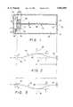
- FIGS. 1, 2 and 3illustrate in diagrammatic form the transverse buckling response of a long slender beam to an axial compressive force
- FIGS. 4, 5 and 6illustrate in diagrammatic form the transverse buckling response of two parallel beams supporting a stage in response to an axial compressive force
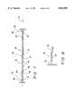
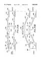
- FIG. 7illustrates in diagrammatic form a segmented beam wherein two rigid axially aligned struts are connected to each other and to an axial actuator by spring hinges;
- FIG. 8is an enlarged view of a typical spring hinge
- FIGS. 9 and 10illustrate in diagrammatic form the transverse buckling response of the segmented beam of FIG. 7 upon application of an axial compressive force
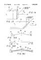
- FIGS. 11, 12 and 13illustrate the use of the segmented beam of FIG. 7 to support a central stage
- FIGS. 14 and 15are diagrammatic illustrations showing the direction of buckling of a slender beam
- FIGS. 16A, 16B and 16Cillustrate perturbations introduced into the segmented beam of FIG. 7 to initiate buckling along a preferred direction
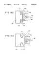
- FIGS. 16D and 16Eillustrate transverse spring supports for the actuator of FIGS. 16A-16C;
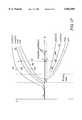
- FIG. 17is a graph illustrating qualitative deformation versus load for a beam
- FIG. 18is graphical illustration of the potential barrier to buckling of a beam
- FIGS. 19A and 19Billustrate in diagrammatic form asymmetric beams carrying a stage and the motion amplification of such a stage
- FIGS. 20A and 20Billustrate in diagrammatic form a stage supported by four segmented beams connected to an actuator and a stage by way of spring hinges;
- FIG. 21illustrates in diagrammatic form a stage carrying a plurality of emitter tips
- FIGS. 22 and 23illustrate in diagrammatic form a mirror supported by plural long slender beams and the motion of the mirror in response to buckling of selected beams;
- FIG. 24illustrates the use of stops to regulate beam motion, resulting in digital motion
- FIG. 25illustrates in diagrammatic form a compound stage controlled by multiple buckling beams.
- FIG. 1a long slender, flexible beam 10 which is clamped at one of its ends 12 and 14 to at least one drive actuator.
- end 14is secured to a fixed reference such as a surface 16
- end 12is secured to a drive actuator such as movable actuator element 18.
- the beam 10preferably is an elongated, thin, flexible microelectromechanical (MEM) structure fabricated, for example, from single crystal silicon utilizing the SCREAM process described above.
- the beam 10may have a length L of, for example, 3-5 millimeters, or more, may have a transverse width W of 1 or 2 micrometers and may have a depth, perpendicular to the plane of FIG. 1, of about 12 micrometers.
- This cross-sectional shapeprovides a beam that has a high aspect ratio so that it is transversely flexible, and is relatively inflexible in the perpendicular direction.
- the beam 10may be fabricated in a cavity or trench 20 formed in a substrate or wafer 22, with the end 14 of the beam being unitary with surface 16 which may be, for example, a wall of the cavity 20 in which the beam is located.
- the end 12 of the beam 10may be unitary with element 18 which preferably is part of an actuator fabricated simultaneously with the fabrication of beam 10, and which may be, for example, the movable part of a comb-type actuator 24 having interleaved movable and stationary fingers 26 and 28, respectively.
- the stationary fingers 28may be fabricated as part of fixed supports 29 extending from the floor of cavity 20.
- the beam 10originates at wall 16 at end 14, and is released for motion with respect to the substrate or wafer from which the device is fabricated, in the manner described, for example, in the aforesaid Pat. No. 5,198,390, with the end 12 being held by actuator 24.
- the movable element 18may be supported by lateral spring arms 30 and 31 extending to the cavity wall.
- the force P applied by the actuator 24causes the ends 12 and 14 of the beam to approach each other by a distance ⁇ after the beam buckles.
- This axial motioncauses a corresponding transverse deformation ⁇ which is defined by Equation 2, above.
- Lis large, this transverse deformation ⁇ is very large in comparison to the value of the axial compression ⁇ , thereby producing in the MEM structure a controllable micromotion amplifier.
- FIGS. 4, 5 and 6An application of the foregoing principle is illustrated in FIGS. 4, 5 and 6, wherein an object to be moved, such as a stage 40, is mounted at the midpoint of two parallel, transversely flexible beams 42 and 44 each connected at one end to a loading, or drive actuator 46, and at the opposite end to a fixed reference 48.
- the drive actuator 46may be a comb-type drive capacitor such as that illustrated at 24 in FIG. 1, while the fixed reference 48 may be the wall of a cavity in a substrate, as illustrated at 16 in FIG. 1.
- Beam 42may be a single flexible beam carrying the stage 40 at its center or may be a pair of flexible beam sections 42' and 42" connected between the actuator 46 and stage 40 and between the fixed reference 48 and stage 40, respectively.
- beam 44may be a single flexible beam carrying the stage or may be a pair of flexible beams 44' and 44".
- application of an axial force P in a direction parallel to the axes of beams 42 and 44results in flexible buckling of the support beams 42 and 44 (or beams 42', 42" and 44', 44") in transverse directions 50 (FIG. 5) or 52 (FIG. 6) to provide controllable amplified transverse motion of the stage in response to axial compressive motion.
- the buckling of beams 42 and 44provides significant motion in the transverse direction ⁇ without fracturing of the beams. It has been found that transverse motion on the order of 100 micrometers is attainable for a beam length of 5 millimeters in response to an actuator motion ⁇ on the order 5 micrometers without fracturing of the beam and with the stage returning to its original position upon release of the force P. This permits highly controllable and repeatable positioning of the stage 40 in response to a controlled force P as a function of the drive voltage applied to the actuator 24. The beam does not fracture because the buckling force P cr for long slender beams is much smaller than the fracture stress.
- the transverse buckling for controlled mechanical amplificationis not limited to flexible MEM beams of the type discussed above.
- a similar operationcan be obtained with segmented rigid MEM beams such as the beam generally illustrated at 60 in FIG. 7.
- the segmented beammay be made up of two rigid struts 62 and 64 connected in end-to-end relationship along a common axis 66 by a flexible connector 68.
- Such a connectormay be a spring, as diagrammatically illustrated at 68, which interconnects the inner, or facing ends 70 and 72 of struts 62 and 64, respectively.
- the outer ends 74 and 76 of struts 62 and 64, respectively,are connected to respective surfaces 78 and 80 by respective flexible connectors such as springs diagrammatically illustrated at 82 and 84.
- each of the rigid struts 62 and 64is fabricated from a pair of parallel MEM beams, such as the beam 10 previously described, with the parallel beams being interconnected by cross bars to provide lateral as well as vertical rigidity.
- a rigid double-beam structureis described, for example, in U.S. patent application Ser. No. 08/067,264 of Kevin A. Shaw, et al., filed May 26, 1993 (attorney's Docket CRF D-1438), now U.S. Pat. No. 5,563,343.
- strut 62is made up of parallel MEM beams 86 and 88 interconnected by a multiplicity of spaced, parallel cross beams 90.
- Strut 64is similarly constructed.
- the springs 68, 82 and 84are also flexible MEM structures and, as illustrated in the enlarged view of FIG. 8, may consist of a single folded or sinuous flexible MEM beam 92 connected at one end to the surface 78 and connected at its opposite end to strut 62.
- the spring 92thus is connected at one end to surface 78, extends axially away from the surface toward strut 62, is folded back on itself to extend toward the surface 78, and is folded back on itself a second time to extend to its connection with strut 62.
- This springmay be similar to beam 10 in that it has a high aspect ratio, i.e., it is narrow so as to be flexible in a direction transverse to the axis of the struts 62 and 64, and has a relatively large depth for rigidity in a direction perpendicular to the plane of transverse motion.
- the springs 68 and 84are similarly constructed, interconnecting the struts 62 and 64 with each other and interconnecting strut 64 with surface 80, as already described.
- FIGS. 9 and 10illustrate the buckling micromotion amplification which occurs, in accordance with the present invention, when actuator 78 applies an axial force to the segmented rigid beam 60 of FIG. 7. As there illustrated, motion of surface 78 an axial distance ⁇ in response to an actuator force P, indicated by arrow 94, results in a buckling of the beam 60 at the central spring 68 and at end springs 82 and 84.
- each of springs 68, 82 and 84is low so that each spring provides minimal resistance against pivoting in the plane of the desired transverse motion of the beam, which is the plane of the drawing in FIGS. 7-10.
- the low resistance of the springscauses them to pivot in the manner of a hinge so that when an axial compressive load is applied at the ends of the strut-spring system of FIG. 7, it will buckle in the manner shown in FIGS. 9 and 10.
- the peak transverse displacement of the systemis as follows: ##EQU3## so that the ⁇ of the segmented rigid beam system is more than twice the ⁇ of a single flexible beam of the type illustrated in FIGS. 1-3.
- the segmented beam of FIG. 7can be used to support an object such as a movable stage by positioning the stage between rigid strut segments in the manner illustrated in FIG. 11.
- a stage 100is supported for transverse motion between a loading actuator 102 and a reference point 104 by rigid segmented beams 106 and 108.
- the beam 106is made up of two rigid strut segments 110 and 112, with strut segment 110 being connected to actuator 102 by a spring 114 and to stage 100 by a spring 116.
- strut segment 112is connected to the reference point 104 by a spring 118 and is connected to stage 100 by a spring 120.
- Segmented beam 108includes a first rigid strut segment 122 connected at one end to actuator 102 by a spring 124 and at its other end to stage 100 by a spring 126.
- the beam 108also includes a rigid strut segment 128 connected between reference point 104 and stage 100 by springs 130 and 132, respectively.
- the cross-section of the beammust be selected so that the moment of inertia I is minimum about the axis which is perpendicular to the desired direction of motion.
- a beam 140 having a width W and a depth Dis oriented so that its depth dimension is parallel to the vertical, or Z axis 142, whereby the minimum moment of inertia I occurs about the axis 142.
- a beam 150 oriented 90° from the beam 140 of FIG. 14has its depth dimension parallel to the Y axis 146 so that a force applied along the X axis 144 will produce buckling in the direction of the Z axis 142.
- the buckling motion ⁇can occur along a selected axis so that motion in three dimensions is available.
- the beams or strutsare symmetrical so that the buckling motion can occur in either an upward or downward direction, as viewed in the figures.
- the beamscan be designed to be asymmetric, as by introduction of a perturbation in the beam so as to cause the beams to buckle in a selected direction.
- a perturbationis illustrated at ⁇ in FIG. 16A, where beam 160 is shaped to have a predetermined bend 162 in its central portion between actuator 164 and reference 166.
- the perturbation ⁇predisposes the beam 162 to flex upwardly in the direction of arrow 168 upon the application of an axial force P.
- FIG. 16Billustrates a different perturbation ⁇ for a beam 170, this perturbation being formed by steps, or shoulders 172 and 174 at opposite ends of the beam rather than the gradual perturbation illustrated in FIG. 16A.
- a rigid segmented beam 180having segments 182 and 184 connected by a spring 186 in the manner described with respect to FIG. 7, may be provided with a perturbation ⁇ at its center; i.e., at the location of spring 186.
- this perturbationprovides a predetermined bend in the beam 180 so that the beam is predisposed to buckle upwardly in the direction of arrow 188 upon application of an axial force P.
- the beamsbuckle upwardly gradually as the axial force P is applied, since buckling in this direction is energetically more favorable.
- the applied force Papproaches the buckling load P cr , a large transverse deformation ⁇ of the asymmetric beam is produced with a small change ⁇ in the location of the drive actuator 164.
- FIG. 17illustrates in diagrammatic form the relationship between the deformation ⁇ and the applied force P.
- a given beamwill deflect, for example along one of the curves 190, 192, 194 or 196.
- Curve 192shows the gradual deformation obtained by a gradual increase of the load P for a particular flexible beam.
- the deformation ⁇can be in either the positive or the negative direction, for example, along curve 198 instead of curve 192 with the beam bending downwardly. This can also happen for a beam that has been buckled upwardly by the force P exceeding P cr , and then being bent downwardly by an external force.
- the beamAfter removal of the external force, the beam would still be at a stable equilibrium but with a bent-down configuration.
- To obtain this bent-down configurationfor example, at point B on curve 198, from a configuration at point A on curve 192, requires an external force sufficient to overcome a large potential barrier such as that illustrated by curve 200 in FIG. 18.
- to move from point A on curve 192 to point B on curve 198requires the application of energy so that the beam shifts from the equilibrium state A to equilibrium state B, with the beam absorbing the energy indicated by the curve.
- At an intermediate point along the energy curve 200there is an unstable region u from which the beam can deflect in either a positive or a negative direction. It should be noted in FIG. 17 that in the region P cr the rate of change of the transverse deformation ⁇ with the force P is very high and at this point the deformation is stable, with perturbation ⁇ 0.
- the force P required to buckle the beamcan be generated by any conventional actuator.
- Such an actuatorcompresses the beam in an axial direction to cause it to buckle.
- the generated forceis absorbed by the beam.
- the beamwill absorb only a small portion of any additional generated force.
- any support springs for the actuatorwill begin to deform as the actuator moves, and thus the bending of the support beams will absorb a major part of any additional applied force. This prevents a sudden uncontrolled motion of the actuator so that the transverse deformation of the buckled beam is stable and gradual.
- FIGS. 16D and 16Eillustrate exemplary support springs for a comb-type actuator such as that illustrated at 164 in FIG. 16A.
- the actuator 164includes a plurality of stationary capacitor fingers 210 interleaved with movable fingers 212, the movable fingers being fabricated as a part of flexible beam 160 (FIG. 16A) or fabricated as part of the spring hinges which connect segmented beam 180 (FIG. 16C) to the actuator.
- a pair of lateral support springs 214 and 216may be provided, the springs extending from the actuator to a fixed reference such as the side wall 218 of a cavity 220 in which the movable beam is located, as described with respect to FIG. 1.
- the beam 160, the movable portion of actuator 164, and the springs 214 and 216are released for movement with respect to the substrate in which the cavity is located, with the springs 214 and 216 holding the fingers 212 in alignment with, and equally spaced from, the fixed fingers 210.
- the springs 214 and 216deform as illustrated in FIG. 16E. This deformation accommodates the actuator motion while retaining the actuator in axial alignment with the beam location. As described above, a part of the force generated by the actuator 164 is required to deform springs 214 and 216, and by careful design of the spring constants of these springs, the buckling of beam 160 and the consequent amplification of the axial motion ⁇ into transverse motion ⁇ is smooth and controlled.
- FIG. 19Aillustrates a pair asymmetrical beams 230 and 232 supporting a movable stage 234, with the beams supporting the stage between a loading actuator 236 and a reference 238.
- the beamseach include perturbations ⁇ , illustrated at 240 and 242 for beam 230, which cause the stage 234 to move upwardly as viewed in the figures, upon application of an axial force P. This motion results in a transverse buckling ⁇ illustrated at 244 in FIG. 19B, in the manner discussed above.
- FIG. 20Aillustrates a movable stage 250 supported between a loading actuator 252 and a reference 254 by four rigid strut members 256, 258 and 260, 262.
- Asymmetrical mounting of the stage 250is obtained by means of flexible springs which offset the mounting struts from the axial center line 264 of the actuator 252. This offset introduces a perturbation in the structure which causes the stage to move upwardly, as illustrated in FIG. 20B by arrow 266, in response to an axial compressive force P.
- the offset mountingis obtained by securing the mounting springs to offset arms on the actuator 252 and on the reference 254, and by providing offset mounting arms on the stage 250.
- loading actuator 252includes a pair of mounting arms 268, 270 having upwardly turned mounting points 272 and 274, respectively, to which mounting springs 276 and 278, respectively, are secured.
- These springsare folded or serpentine, with spring 276, for example, including a first segment 280 extending from mounting point 272 toward the actuator 252 and having a second segment 282 which is folded back on the first segment and which extends to a connection point at one end of the strut 256.
- Spring 278is similarly mounted on actuator 252 and struts 258 and 262 are similarly mounted on the reference 254 by folded springs 284 and 286, respectively.
- Stage 250includes a generally T-shaped mounting arm 288 to which is connected a folded mounting spring 290 for connecting a second end of strut 256 to the stage and a folded spring 292 for connecting strut 258 to the stage.
- struts 260 and 262are secured to the stage by folded springs 294 and 296.
- These folded springsprovide a flexible connection so that in response to an axial force applied by actuator 252, the mounting springs flex in the manner of hinges in the plane of transverse motion to cause the struts 256, 258, 260 and 262 and their attached springs to buckle upwardly to move the stage 250 the distance ⁇ in a direction transverse to the axis 264.
- the stage 250may take a variety of forms, but as illustrated in FIG. 21, in one preferred form the stage is fabricated from a plurality of beam sections 300 to form a grid, with a plurality of tunneling tips, emitting tips, or the like, indicated at 302 mounted on the top surface of the stage.
- the stagemay be supported, for example, by flexible beams such as the beams 230 and 232 illustrated in FIG. 19A, with the entire device being fabricated by the SCREAM process described above.
- FIG. 22An application of the micromotion amplifier of the present invention is illustrated in FIG. 22 wherein three flexible beams 310, 312, and 314 are connected in parallel between a reference, or stationary support 316 and corresponding movable actuators 318, 320 and 322.
- the actuatorsmay be comb-type capacitors having movable and fixed interleaved fingers such as the movable fingers 324 and the fixed fingers 326 of actuator 318.
- the fixed fingersmay be mounted on supports 328 on the floor of a cavity 329 in the fixed substrate, which may include the fixed reference 316, so that a voltage applied between the fixed and movable fingers of a selected actuator will produce an axial force P upon the corresponding flexible beam.
- the beams 310, 312, and 314are oriented to flex in an upward direction, as viewed in FIG. 22 and as illustrated for beam 312 in FIG. 23, with each beam being separately movable under the control of its respective actuator.
- a micromirror 330which may be fabricated from a polysilicon layer, is secured at one of its ends to a pair of torsion bars 332 and 333 which extend between the mirror and the adjacent fixed substrate region 316.
- the barsmount the mirror for pivotal motion, with the mirror lying on, but not attached to, the three flexible beams 310, 312, and 314.
- the bars 332 and 333allow the mirror to pivot upwardly when any one of the beams 310, 312, and 314 is activated to buckle upwardly in the manner illustrated in FIG. 23 for beam 312.
- the buckling of a selected flexible beamcauses the mirror 330 to pivot about torsional springs 332, 333, with the degree of tilt of the mirror about the torsional spring being dependent upon which beam is activated and upon the amplitude of the force P applied to that beam.
- the tilt angle of the mirroris small when beam 310 is buckled, and is large when beam 314 is tilted, with the three beams being selectable to provide a high degree of precision for the tilting of the mirror.
- the micromirror 330may be used to reflect laser light, or the like, for scanning or other known uses.
- the beams 310, 312 and 314are continuously variable in the device illustrated in FIGS. 22 and 23 to provide continuous, or analog, control of mirror location under the control of the actuators.
- a digital control of the mirror positioncan be obtained by providing positive stops for the actuators, as illustrated by stops 336 and 337 for actuator 318 in FIG. 24. Similar stops can be provided for each of the other beams 312 and 314 to engage the respective actuators 320 and 322, so that these selectable tilt positions are provided. This arrangement precisely positions the mirror in a predetermined position in response to energization of actuator to provide digital positioning.
- FIG. 25Two dimensional controlled motion of a central stage is obtained, in accordance with one embodiment of the invention, by mounting a central stage for motion within an intermediate stage, with the intermediate stage itself being mounted for relative motion with respect to a surrounding substrate.
- stage 350is mounted between a loading actuator 354 and a reference 356 by means of offset, or asymmetrical beams 358, 360 and 362, 364.
- Energization of actuator 354 to produce an axial force P 1 on flexible beams 358, 360 and 362, 364causes the stage 350 to shift in the direction indicated by arrow 366, along an X axis.
- the actuator 354 and reference 356are mounted on the intermediate stage 352 which is, in turn, supported by asymmetrical flexible beams 370, 372 and 374, 376 between a loading actuator 380 and a reference 382.
- Energization of actuator 380 to produce an axial force P in a direction indicated by arrow 384causes the beams 370, 372 and 374, 376 to buckle upwardly in the direction indicated by arrow 386 along a Y axis to cause stage 352 and its included stage 350 to move along the Y axis.
- X and Y motion of the stage 350can be accomplished.
Landscapes
- Physics & Mathematics (AREA)
- Engineering & Computer Science (AREA)
- Computer Hardware Design (AREA)
- Microelectronics & Electronic Packaging (AREA)
- General Physics & Mathematics (AREA)
- Optics & Photonics (AREA)
- Micromachines (AREA)
Abstract
Description
P≦P.sub.cr =4π.sup.2 EI/L.sup.2 (Eq. 3)
Claims (18)
Priority Applications (1)
| Application Number | Priority Date | Filing Date | Title |
|---|---|---|---|
| US08/667,880US5862003A (en) | 1995-06-23 | 1996-06-20 | Micromotion amplifier |
Applications Claiming Priority (2)
| Application Number | Priority Date | Filing Date | Title |
|---|---|---|---|
| US43795P | 1995-06-23 | 1995-06-23 | |
| US08/667,880US5862003A (en) | 1995-06-23 | 1996-06-20 | Micromotion amplifier |
Publications (1)
| Publication Number | Publication Date |
|---|---|
| US5862003Atrue US5862003A (en) | 1999-01-19 |
Family
ID=26667627
Family Applications (1)
| Application Number | Title | Priority Date | Filing Date |
|---|---|---|---|
| US08/667,880Expired - LifetimeUS5862003A (en) | 1995-06-23 | 1996-06-20 | Micromotion amplifier |
Country Status (1)
| Country | Link |
|---|---|
| US (1) | US5862003A (en) |
Cited By (68)
| Publication number | Priority date | Publication date | Assignee | Title |
|---|---|---|---|---|
| US5955817A (en)* | 1996-12-16 | 1999-09-21 | Mcnc | Thermal arched beam microelectromechanical switching array |
| US5962949A (en)* | 1996-12-16 | 1999-10-05 | Mcnc | Microelectromechanical positioning apparatus |
| US6007208A (en)* | 1995-12-19 | 1999-12-28 | The Board Of Trustees Of The Leland Stanford Junior University | Miniature scanning confocal microscope |
| US6137206A (en)* | 1999-03-23 | 2000-10-24 | Cronos Integrated Microsystems, Inc. | Microelectromechanical rotary structures |
| WO2000067268A1 (en)* | 1999-05-03 | 2000-11-09 | Cronos Integrated Microsystems, Inc. | Multi-dimensional scalable displacement enabled microelectromechanical actuator structures and arrays |
| US6211598B1 (en) | 1999-09-13 | 2001-04-03 | Jds Uniphase Inc. | In-plane MEMS thermal actuator and associated fabrication methods |
| US6236139B1 (en) | 1999-02-26 | 2001-05-22 | Jds Uniphase Inc. | Temperature compensated microelectromechanical structures and related methods |
| US6255757B1 (en) | 1999-09-01 | 2001-07-03 | Jds Uniphase Inc. | Microactuators including a metal layer on distal portions of an arched beam |
| US6275320B1 (en) | 1999-09-27 | 2001-08-14 | Jds Uniphase, Inc. | MEMS variable optical attenuator |
| US6283601B1 (en)* | 2000-04-14 | 2001-09-04 | C Speed Corporation | Optical mirror system with multi-axis rotational control |
| US6285400B1 (en)* | 1996-09-26 | 2001-09-04 | Nec Corporation | Solid state image pick-up device equipped with charge coupled device having incident surface alignable with focal plane |
| US6291922B1 (en) | 1999-08-25 | 2001-09-18 | Jds Uniphase, Inc. | Microelectromechanical device having single crystalline components and metallic components |
| US6309077B1 (en)* | 1999-01-12 | 2001-10-30 | Cornell Research Foundation Inc. | Motion amplification based sensors |
| US6317229B1 (en)* | 2000-10-06 | 2001-11-13 | Randall Frederick Otterson | Adjustable mirror |
| US6364460B1 (en) | 2000-06-13 | 2002-04-02 | Chad R. Sager | Liquid delivery system |
| US6373682B1 (en) | 1999-12-15 | 2002-04-16 | Mcnc | Electrostatically controlled variable capacitor |
| US6377438B1 (en) | 2000-10-23 | 2002-04-23 | Mcnc | Hybrid microelectromechanical system tunable capacitor and associated fabrication methods |
| US20020050763A1 (en)* | 2000-10-05 | 2002-05-02 | Nat'l Inst Of Advanced Industrial Sci And Tech | Slider displacement direction conversion mechanism in electrostatic actuator |
| US6396620B1 (en) | 2000-10-30 | 2002-05-28 | Mcnc | Electrostatically actuated electromagnetic radiation shutter |
| US20020102743A1 (en)* | 1999-08-19 | 2002-08-01 | The Regents Of The University Of California | Apparatus and method for visually identifying micro-forces with a palette of cantilever array blocks |
| US6445107B1 (en)* | 2000-07-18 | 2002-09-03 | Samsung Electronics Co., Ltd. | Single stage microactuator for multi-dimensional actuation |
| US20020128585A1 (en)* | 2000-07-07 | 2002-09-12 | Cork William H | Medical system, method and apparatus employing mems |
| US6485273B1 (en) | 2000-09-01 | 2002-11-26 | Mcnc | Distributed MEMS electrostatic pumping devices |
| KR100374486B1 (en)* | 2001-02-22 | 2003-03-03 | 주식회사 나노위즈 | Thin film micromirror array for free-space optical switching using Micro Electro Mechanical System and method for manufacturing the same, and multidimensional optical switching mode therefrom |
| US6541892B2 (en)* | 2001-01-16 | 2003-04-01 | Agilent Technologies, Inc. | Actuator with a flexure arrangement to accommodate a long range of motion |
| US6545385B2 (en)* | 2000-04-11 | 2003-04-08 | Sandia Corporation | Microelectromechanical apparatus for elevating and tilting a platform |
| WO2002046819A3 (en)* | 2000-12-04 | 2003-06-05 | Siemens Ag | Tilting mirror device |
| US6590313B2 (en) | 1999-02-26 | 2003-07-08 | Memscap S.A. | MEMS microactuators located in interior regions of frames having openings therein and methods of operating same |
| US6590267B1 (en) | 2000-09-14 | 2003-07-08 | Mcnc | Microelectromechanical flexible membrane electrostatic valve device and related fabrication methods |
| US6598985B2 (en)* | 2001-06-11 | 2003-07-29 | Nanogear | Optical mirror system with multi-axis rotational control |
| US20030154149A1 (en)* | 2002-02-13 | 2003-08-14 | Dilip Gajendragadkar | System and method of creating and executing a restricted stock sale plan |
| WO2002068319A3 (en)* | 2001-02-27 | 2003-08-21 | Litton Systems Inc | Bi-stable micro-actuator and optical switch |
| US20030173865A1 (en)* | 2002-03-14 | 2003-09-18 | Miller Samuel Lee | Microelectromechanical system with stiff coupling |
| US20030173866A1 (en)* | 2002-03-14 | 2003-09-18 | Miller Samuel Lee | Microelectromechanical system & method for producing displacement multiplication |
| WO2002092496A3 (en)* | 2001-05-14 | 2003-10-23 | Univ Michigan | High-performance fully-compliant micro-mechanisms for force/displacement amplification |
| US6647164B1 (en) | 2000-10-31 | 2003-11-11 | 3M Innovative Properties Company | Gimbaled micro-mirror positionable by thermal actuators |
| US20030227114A1 (en)* | 2002-02-07 | 2003-12-11 | Samsung Electronics Co., Ltd. | Torsion spring for MEMS structure |
| US6665104B2 (en) | 2002-03-12 | 2003-12-16 | Memx, Inc. | Mirror positioning assembly with vertical force component compensation |
| US6711318B2 (en) | 2001-01-29 | 2004-03-23 | 3M Innovative Properties Company | Optical switch based on rotating vertical micro-mirror |
| US20040062510A1 (en)* | 2002-09-30 | 2004-04-01 | Romo Mark George | Variable optical attenuator |
| WO2003014009A3 (en)* | 2001-08-07 | 2004-04-08 | Hewlett Packard Co | A microelectromechanical device having a stiffened support beam, and methods of forming stiffened support beams in mems |
| US6788840B2 (en) | 2001-02-27 | 2004-09-07 | Northrop Grumman Corporation | Bi-stable micro-actuator and optical switch |
| US20040223717A1 (en)* | 2003-05-06 | 2004-11-11 | Romo Mark George | Variable optical attenuator |
| US20040223204A1 (en)* | 2003-05-09 | 2004-11-11 | Minyao Mao | Bistable latching actuator for optical switching applications |
| US20040245888A1 (en)* | 2003-06-05 | 2004-12-09 | Aksyuk Vladimir A. | Deformable MEMS mirror |
| US20050031288A1 (en)* | 2003-08-05 | 2005-02-10 | Xerox Corporation. | Thermal actuator and an optical waveguide switch including the same |
| US6886916B1 (en) | 2003-06-18 | 2005-05-03 | Sandia Corporation | Piston-driven fluid-ejection apparatus |
| US20050196099A1 (en)* | 2004-03-04 | 2005-09-08 | Rosemount Inc. | MEMS-based actuator devices using electrets |
| US6960849B1 (en) | 2003-03-31 | 2005-11-01 | Sandia Corporation | Three-dimensional microelectromechanical tilting platform operated by gear-driven racks |
| US20050248860A1 (en)* | 2004-05-04 | 2005-11-10 | Herman Soemers | High positioning reproducible low torque mirror - actuator interface |
| US6985651B2 (en)* | 2003-08-05 | 2006-01-10 | Xerox Corporation | Thermal actuator with offset beam segment neutral axes and an optical waveguide switch including the same |
| US6985650B2 (en)* | 2003-08-05 | 2006-01-10 | Xerox Corporation | Thermal actuator and an optical waveguide switch including the same |
| US20060016481A1 (en)* | 2004-07-23 | 2006-01-26 | Douglas Kevin R | Methods of operating microvalve assemblies and related structures and related devices |
| US20060056004A1 (en)* | 2004-09-14 | 2006-03-16 | Adel Jilani | Flexure |
| US7055975B2 (en) | 2002-03-12 | 2006-06-06 | Memx, Inc. | Microelectromechanical system with non-collinear force compensation |
| US20060151864A1 (en)* | 2005-01-11 | 2006-07-13 | Rosemount Inc. | MEMS packaging with improved reaction to temperature changes |
| EP1717631A1 (en)* | 2005-04-25 | 2006-11-02 | Fraunhofer-Gesellschaft zur Förderung der angewandten Forschung e.V. | Micro-optical arrangement |
| US20070214890A1 (en)* | 2006-01-31 | 2007-09-20 | Ranjan Mukherjee | MEMS resonator using frequency tuning |
| US7450812B2 (en) | 2003-05-06 | 2008-11-11 | Rosemount Inc. | Compensated variable optical attenuator |
| US20100295414A1 (en)* | 2006-09-22 | 2010-11-25 | Cornell Research Foundation, Inc. | Coupled mems structure for motion amplification |
| WO2013171357A1 (en)* | 2012-05-15 | 2013-11-21 | Universitat Politècnica De Catalunya | Beam for a movement amplifying device and movement amplifying device using said beam |
| CN103471745A (en)* | 2013-09-16 | 2013-12-25 | 清华大学 | Buckling micro-force sensor and micro-force measuring method based on twin beams or serial connection twin beams |
| US9366031B2 (en)* | 2013-04-10 | 2016-06-14 | Avtechtyee Inc. | Eccentrically loaded structural members and methods of forming the same |
| EP3140563A4 (en)* | 2014-05-06 | 2018-01-17 | Mems Drive Inc. | Low stiffness flexure |
| US20180348436A1 (en)* | 2017-05-30 | 2018-12-06 | Pierre Pottier | Micromechanically actuated deformable optical beam steering for wavelength tunable optical sources, filters and detectors |
| US10244171B2 (en) | 2014-05-06 | 2019-03-26 | Mems Drive, Inc. | Electrical bar latching for low stiffness flexure MEMS actuator |
| US10730740B2 (en) | 2014-04-01 | 2020-08-04 | Agiltron, Inc. | Microelectromechanical displacement structure and method for controlling displacement |
| US11054908B2 (en)* | 2017-07-28 | 2021-07-06 | Synaptics Incorporated | Haptic tactile feedback with buckling mechanism |
Citations (7)
| Publication number | Priority date | Publication date | Assignee | Title |
|---|---|---|---|---|
| US1910119A (en)* | 1932-05-23 | 1933-05-23 | De Witt T Moats | Automobile rear view reflector |
| US4919500A (en)* | 1988-09-09 | 1990-04-24 | General Scanning, Inc. | Torsion bar scanner with damping |
| DE4000496A1 (en)* | 1989-08-17 | 1991-02-21 | Bosch Gmbh Robert | METHOD FOR STRUCTURING A SEMICONDUCTOR BODY |
| US5005298A (en)* | 1986-09-09 | 1991-04-09 | Hitachi Construction Machinery Co., Ltd. | Displacement controller for fine positioning device |
| US5179499A (en)* | 1992-04-14 | 1993-01-12 | Cornell Research Foundation, Inc. | Multi-dimensional precision micro-actuator |
| US5198390A (en)* | 1992-01-16 | 1993-03-30 | Cornell Research Foundation, Inc. | RIE process for fabricating submicron, silicon electromechanical structures |
| US5235187A (en)* | 1991-05-14 | 1993-08-10 | Cornell Research Foundation | Methods of fabricating integrated, aligned tunneling tip pairs |
- 1996
- 1996-06-20USUS08/667,880patent/US5862003A/ennot_activeExpired - Lifetime
Patent Citations (9)
| Publication number | Priority date | Publication date | Assignee | Title |
|---|---|---|---|---|
| US1910119A (en)* | 1932-05-23 | 1933-05-23 | De Witt T Moats | Automobile rear view reflector |
| US5005298A (en)* | 1986-09-09 | 1991-04-09 | Hitachi Construction Machinery Co., Ltd. | Displacement controller for fine positioning device |
| US4919500A (en)* | 1988-09-09 | 1990-04-24 | General Scanning, Inc. | Torsion bar scanner with damping |
| DE4000496A1 (en)* | 1989-08-17 | 1991-02-21 | Bosch Gmbh Robert | METHOD FOR STRUCTURING A SEMICONDUCTOR BODY |
| US5235187A (en)* | 1991-05-14 | 1993-08-10 | Cornell Research Foundation | Methods of fabricating integrated, aligned tunneling tip pairs |
| US5198390A (en)* | 1992-01-16 | 1993-03-30 | Cornell Research Foundation, Inc. | RIE process for fabricating submicron, silicon electromechanical structures |
| US5316979A (en)* | 1992-01-16 | 1994-05-31 | Cornell Research Foundation, Inc. | RIE process for fabricating submicron, silicon electromechanical structures |
| US5179499A (en)* | 1992-04-14 | 1993-01-12 | Cornell Research Foundation, Inc. | Multi-dimensional precision micro-actuator |
| US5375033A (en)* | 1992-04-14 | 1994-12-20 | Cornell Research Foundation, Inc. | Multi-dimensional precision micro-actuator |
Non-Patent Citations (10)
| Title |
|---|
| Haengsoo Lee, et al., "Finite Element Analysis of Lateral Buckling for Beam Structures", Computers and Structures, 1994, vol. 53, No. 6 pp.1357-1371. |
| Haengsoo Lee, et al., Finite Element Analysis of Lateral Buckling for Beam Structures , Computers and Structures, 1994, vol. 53, No. 6 pp.1357 1371.* |
| Reid A. Brenne, et al., "Large Displacement Linear Actuator", IEEE, CH2783-9/90, 1990, pp. 135-139. |
| Reid A. Brenne, et al., Large Displacement Linear Actuator , IEEE, CH2783 9/90, 1990, pp. 135 139.* |
| Savoia et al., "Post-buckling Behavior of Stiffened Cross-Ply Cylindrical Shells", J. of Applied Mechanics, Dec. 1994, vol. 61, pp. 998-1000. |
| Savoia et al., Post buckling Behavior of Stiffened Cross Ply Cylindrical Shells , J. of Applied Mechanics, Dec. 1994, vol. 61, pp. 998 1000.* |
| Stephen P. Timoshenko, et al., "Theory of Elastic Stability", Eng. Societies Monographs, 1961, pp. 46-83. |
| Stephen P. Timoshenko, et al., Theory of Elastic Stability , Eng. Societies Monographs, 1961, pp. 46 83.* |
| Ulf Lindbergt, et al., "Quasi-buckling of Micromachined Beams", Micromech, Microeng. 3 (1993), pp. 183-186. |
| Ulf Lindbergt, et al., Quasi buckling of Micromachined Beams , Micromech, Microeng. 3 (1993), pp. 183 186.* |
Cited By (118)
| Publication number | Priority date | Publication date | Assignee | Title |
|---|---|---|---|---|
| US6007208A (en)* | 1995-12-19 | 1999-12-28 | The Board Of Trustees Of The Leland Stanford Junior University | Miniature scanning confocal microscope |
| US6154305A (en)* | 1995-12-19 | 2000-11-28 | The Board Of Trustees Of The Leland Stanford Junior University | Miniature scanning confocal microscope |
| US6285400B1 (en)* | 1996-09-26 | 2001-09-04 | Nec Corporation | Solid state image pick-up device equipped with charge coupled device having incident surface alignable with focal plane |
| US5955817A (en)* | 1996-12-16 | 1999-09-21 | Mcnc | Thermal arched beam microelectromechanical switching array |
| US6023121A (en)* | 1996-12-16 | 2000-02-08 | Mcnc | Thermal arched beam microelectromechanical structure |
| US6114794A (en)* | 1996-12-16 | 2000-09-05 | Cronos Integrated Microsystems, Inc. | Thermal arched beam microelectromechanical valve |
| US6324748B1 (en) | 1996-12-16 | 2001-12-04 | Jds Uniphase Corporation | Method of fabricating a microelectro mechanical structure having an arched beam |
| US5994816A (en)* | 1996-12-16 | 1999-11-30 | Mcnc | Thermal arched beam microelectromechanical devices and associated fabrication methods |
| US5962949A (en)* | 1996-12-16 | 1999-10-05 | Mcnc | Microelectromechanical positioning apparatus |
| US6309077B1 (en)* | 1999-01-12 | 2001-10-30 | Cornell Research Foundation Inc. | Motion amplification based sensors |
| US6590313B2 (en) | 1999-02-26 | 2003-07-08 | Memscap S.A. | MEMS microactuators located in interior regions of frames having openings therein and methods of operating same |
| US6596147B2 (en) | 1999-02-26 | 2003-07-22 | Memscap S.A. | Methods of overplating surfaces of microelectromechanical structure |
| US6236139B1 (en) | 1999-02-26 | 2001-05-22 | Jds Uniphase Inc. | Temperature compensated microelectromechanical structures and related methods |
| US6137206A (en)* | 1999-03-23 | 2000-10-24 | Cronos Integrated Microsystems, Inc. | Microelectromechanical rotary structures |
| US6218762B1 (en) | 1999-05-03 | 2001-04-17 | Mcnc | Multi-dimensional scalable displacement enabled microelectromechanical actuator structures and arrays |
| WO2000067268A1 (en)* | 1999-05-03 | 2000-11-09 | Cronos Integrated Microsystems, Inc. | Multi-dimensional scalable displacement enabled microelectromechanical actuator structures and arrays |
| US20020102743A1 (en)* | 1999-08-19 | 2002-08-01 | The Regents Of The University Of California | Apparatus and method for visually identifying micro-forces with a palette of cantilever array blocks |
| US7105358B2 (en) | 1999-08-19 | 2006-09-12 | The Regents Of The University Of California | Apparatus and method for visually identifying micro-forces with a palette of cantilever array blocks |
| US6291922B1 (en) | 1999-08-25 | 2001-09-18 | Jds Uniphase, Inc. | Microelectromechanical device having single crystalline components and metallic components |
| US6628039B2 (en) | 1999-08-25 | 2003-09-30 | Memscap, S.A. | Microelectromechanical device having single crystalline components and metallic components |
| US6255757B1 (en) | 1999-09-01 | 2001-07-03 | Jds Uniphase Inc. | Microactuators including a metal layer on distal portions of an arched beam |
| US6386507B2 (en) | 1999-09-01 | 2002-05-14 | Jds Uniphase Corporation | Microelectromechanical valves including single crystalline material components |
| US6211598B1 (en) | 1999-09-13 | 2001-04-03 | Jds Uniphase Inc. | In-plane MEMS thermal actuator and associated fabrication methods |
| US6410361B2 (en) | 1999-09-13 | 2002-06-25 | Jds Uniphase Corporation | Methods of fabricating in-plane MEMS thermal actuators |
| US6275320B1 (en) | 1999-09-27 | 2001-08-14 | Jds Uniphase, Inc. | MEMS variable optical attenuator |
| US6373682B1 (en) | 1999-12-15 | 2002-04-16 | Mcnc | Electrostatically controlled variable capacitor |
| US6545385B2 (en)* | 2000-04-11 | 2003-04-08 | Sandia Corporation | Microelectromechanical apparatus for elevating and tilting a platform |
| US6759787B2 (en) | 2000-04-11 | 2004-07-06 | Sandia Corporation | Microelectromechanical apparatus for elevating and tilting a platform |
| US6386716B2 (en)* | 2000-04-14 | 2002-05-14 | C Speed Corporation | Optical mirror system with multi-axis rotational control |
| US6283601B1 (en)* | 2000-04-14 | 2001-09-04 | C Speed Corporation | Optical mirror system with multi-axis rotational control |
| US6364460B1 (en) | 2000-06-13 | 2002-04-02 | Chad R. Sager | Liquid delivery system |
| US20050269251A1 (en)* | 2000-07-07 | 2005-12-08 | Cork William H | Medical system, method and apparatus employing MEMS |
| US6994781B2 (en) | 2000-07-07 | 2006-02-07 | Baxter International Inc. | Medical system, method and apparatus employing MEMS |
| US7217356B2 (en) | 2000-07-07 | 2007-05-15 | Fenwal, Inc. | Medical system, method and apparatus employing MEMS |
| US20050269250A1 (en)* | 2000-07-07 | 2005-12-08 | Cork William H | Medical system, method and apparatus employing MEMS |
| US20020128585A1 (en)* | 2000-07-07 | 2002-09-12 | Cork William H | Medical system, method and apparatus employing mems |
| US6445107B1 (en)* | 2000-07-18 | 2002-09-03 | Samsung Electronics Co., Ltd. | Single stage microactuator for multi-dimensional actuation |
| US6485273B1 (en) | 2000-09-01 | 2002-11-26 | Mcnc | Distributed MEMS electrostatic pumping devices |
| US6590267B1 (en) | 2000-09-14 | 2003-07-08 | Mcnc | Microelectromechanical flexible membrane electrostatic valve device and related fabrication methods |
| US20020050763A1 (en)* | 2000-10-05 | 2002-05-02 | Nat'l Inst Of Advanced Industrial Sci And Tech | Slider displacement direction conversion mechanism in electrostatic actuator |
| US6781280B2 (en)* | 2000-10-05 | 2004-08-24 | National Institute Of Advanced Industrial Science And Technology | Slider displacement direction conversion mechanism in electrostatic actuator |
| US6317229B1 (en)* | 2000-10-06 | 2001-11-13 | Randall Frederick Otterson | Adjustable mirror |
| US6377438B1 (en) | 2000-10-23 | 2002-04-23 | Mcnc | Hybrid microelectromechanical system tunable capacitor and associated fabrication methods |
| US6396620B1 (en) | 2000-10-30 | 2002-05-28 | Mcnc | Electrostatically actuated electromagnetic radiation shutter |
| US6647164B1 (en) | 2000-10-31 | 2003-11-11 | 3M Innovative Properties Company | Gimbaled micro-mirror positionable by thermal actuators |
| WO2002046819A3 (en)* | 2000-12-04 | 2003-06-05 | Siemens Ag | Tilting mirror device |
| US6541892B2 (en)* | 2001-01-16 | 2003-04-01 | Agilent Technologies, Inc. | Actuator with a flexure arrangement to accommodate a long range of motion |
| US6711318B2 (en) | 2001-01-29 | 2004-03-23 | 3M Innovative Properties Company | Optical switch based on rotating vertical micro-mirror |
| KR100374486B1 (en)* | 2001-02-22 | 2003-03-03 | 주식회사 나노위즈 | Thin film micromirror array for free-space optical switching using Micro Electro Mechanical System and method for manufacturing the same, and multidimensional optical switching mode therefrom |
| US6788840B2 (en) | 2001-02-27 | 2004-09-07 | Northrop Grumman Corporation | Bi-stable micro-actuator and optical switch |
| WO2002068319A3 (en)* | 2001-02-27 | 2003-08-21 | Litton Systems Inc | Bi-stable micro-actuator and optical switch |
| US6748818B2 (en)* | 2001-05-14 | 2004-06-15 | The Regents Of The University Of Michigan | High-performance fully-compliant micro-mechanisms for force/displacement amplification |
| WO2002092496A3 (en)* | 2001-05-14 | 2003-10-23 | Univ Michigan | High-performance fully-compliant micro-mechanisms for force/displacement amplification |
| US6598985B2 (en)* | 2001-06-11 | 2003-07-29 | Nanogear | Optical mirror system with multi-axis rotational control |
| WO2003014009A3 (en)* | 2001-08-07 | 2004-04-08 | Hewlett Packard Co | A microelectromechanical device having a stiffened support beam, and methods of forming stiffened support beams in mems |
| US20030227114A1 (en)* | 2002-02-07 | 2003-12-11 | Samsung Electronics Co., Ltd. | Torsion spring for MEMS structure |
| US6921952B2 (en)* | 2002-02-07 | 2005-07-26 | Samsung Electronics Co., Ltd. | Torsion spring for MEMS structure |
| US20030154149A1 (en)* | 2002-02-13 | 2003-08-14 | Dilip Gajendragadkar | System and method of creating and executing a restricted stock sale plan |
| US7055975B2 (en) | 2002-03-12 | 2006-06-06 | Memx, Inc. | Microelectromechanical system with non-collinear force compensation |
| US6665104B2 (en) | 2002-03-12 | 2003-12-16 | Memx, Inc. | Mirror positioning assembly with vertical force component compensation |
| US6831390B2 (en)* | 2002-03-14 | 2004-12-14 | Memx, Inc. | Microelectromechanical system with stiff coupling |
| US6844657B2 (en) | 2002-03-14 | 2005-01-18 | Memx, Inc. | Microelectromechanical system and method for producing displacement multiplication |
| US20030173865A1 (en)* | 2002-03-14 | 2003-09-18 | Miller Samuel Lee | Microelectromechanical system with stiff coupling |
| US20030173866A1 (en)* | 2002-03-14 | 2003-09-18 | Miller Samuel Lee | Microelectromechanical system & method for producing displacement multiplication |
| US20040062510A1 (en)* | 2002-09-30 | 2004-04-01 | Romo Mark George | Variable optical attenuator |
| US6895161B2 (en) | 2002-09-30 | 2005-05-17 | Rosemount Inc. | Variable optical attenuator |
| US6960849B1 (en) | 2003-03-31 | 2005-11-01 | Sandia Corporation | Three-dimensional microelectromechanical tilting platform operated by gear-driven racks |
| US7197225B2 (en) | 2003-05-06 | 2007-03-27 | Rosemount Inc. | Variable optical attenuator |
| US20040223717A1 (en)* | 2003-05-06 | 2004-11-11 | Romo Mark George | Variable optical attenuator |
| US7450812B2 (en) | 2003-05-06 | 2008-11-11 | Rosemount Inc. | Compensated variable optical attenuator |
| US6865313B2 (en)* | 2003-05-09 | 2005-03-08 | Opticnet, Inc. | Bistable latching actuator for optical switching applications |
| US20040223204A1 (en)* | 2003-05-09 | 2004-11-11 | Minyao Mao | Bistable latching actuator for optical switching applications |
| WO2004102240A1 (en)* | 2003-05-09 | 2004-11-25 | Opticnet, Inc. | Bistable latching actuator for optical switching applications |
| US6998758B2 (en)* | 2003-06-05 | 2006-02-14 | Lucent Technologies Inc. | Deformable MEMS mirror with membrane actuated by application of torque |
| US20040245888A1 (en)* | 2003-06-05 | 2004-12-09 | Aksyuk Vladimir A. | Deformable MEMS mirror |
| US6886916B1 (en) | 2003-06-18 | 2005-05-03 | Sandia Corporation | Piston-driven fluid-ejection apparatus |
| US6985651B2 (en)* | 2003-08-05 | 2006-01-10 | Xerox Corporation | Thermal actuator with offset beam segment neutral axes and an optical waveguide switch including the same |
| US20050031288A1 (en)* | 2003-08-05 | 2005-02-10 | Xerox Corporation. | Thermal actuator and an optical waveguide switch including the same |
| US6985650B2 (en)* | 2003-08-05 | 2006-01-10 | Xerox Corporation | Thermal actuator and an optical waveguide switch including the same |
| US6983088B2 (en)* | 2003-08-05 | 2006-01-03 | Xerox Corporation | Thermal actuator and an optical waveguide switch including the same |
| US7177505B2 (en) | 2004-03-04 | 2007-02-13 | Rosemount Inc. | MEMS-based actuator devices using electrets |
| US20050196099A1 (en)* | 2004-03-04 | 2005-09-08 | Rosemount Inc. | MEMS-based actuator devices using electrets |
| US20110176234A1 (en)* | 2004-05-04 | 2011-07-21 | Carl Zeiss Smt Gmbh | High positioning reproducible low torque mirror - actuator interface |
| US20100149671A1 (en)* | 2004-05-04 | 2010-06-17 | Carl Zeiss Smt Ag | High positioning reproducible low torque mirror - actuator interface |
| US8256912B2 (en) | 2004-05-04 | 2012-09-04 | Carl Zeiss Smt Gmbh | High positioning reproducible low torque mirror-actuator interface |
| US7699480B2 (en) | 2004-05-04 | 2010-04-20 | Carl Zeiss Smt Ag | High positioning reproducible low torque mirror-actuator interface |
| US7604359B2 (en)* | 2004-05-04 | 2009-10-20 | Carl Zeiss Smt Ag | High positioning reproducible low torque mirror-actuator interface |
| US20090103199A1 (en)* | 2004-05-04 | 2009-04-23 | Herman Soemers | High positioning reproducible low torque mirror - actuator interface |
| US20050248860A1 (en)* | 2004-05-04 | 2005-11-10 | Herman Soemers | High positioning reproducible low torque mirror - actuator interface |
| US7448412B2 (en) | 2004-07-23 | 2008-11-11 | Afa Controls Llc | Microvalve assemblies and related structures and related methods |
| US7753072B2 (en) | 2004-07-23 | 2010-07-13 | Afa Controls Llc | Valve assemblies including at least three chambers and related methods |
| US20060016481A1 (en)* | 2004-07-23 | 2006-01-26 | Douglas Kevin R | Methods of operating microvalve assemblies and related structures and related devices |
| US20090032112A1 (en)* | 2004-07-23 | 2009-02-05 | Afa Controls Llc | Methods of Packaging Valve Chips and Related Valve Assemblies |
| US20060016486A1 (en)* | 2004-07-23 | 2006-01-26 | Teach William O | Microvalve assemblies and related structures and related methods |
| US20110132484A1 (en)* | 2004-07-23 | 2011-06-09 | Teach William O | Valve Assemblies Including Electrically Actuated Valves |
| US7946308B2 (en) | 2004-07-23 | 2011-05-24 | Afa Controls Llc | Methods of packaging valve chips and related valve assemblies |
| US20100236644A1 (en)* | 2004-07-23 | 2010-09-23 | Douglas Kevin R | Methods of Operating Microvalve Assemblies and Related Structures and Related Devices |
| US7623142B2 (en) | 2004-09-14 | 2009-11-24 | Hewlett-Packard Development Company, L.P. | Flexure |
| US20060056004A1 (en)* | 2004-09-14 | 2006-03-16 | Adel Jilani | Flexure |
| US20060151864A1 (en)* | 2005-01-11 | 2006-07-13 | Rosemount Inc. | MEMS packaging with improved reaction to temperature changes |
| US7642628B2 (en) | 2005-01-11 | 2010-01-05 | Rosemount Inc. | MEMS packaging with improved reaction to temperature changes |
| US7301690B2 (en) | 2005-04-25 | 2007-11-27 | Fraunhofer-Gesellschaft Zur Foerderung Der Angewandten Forschung E.V. | Micro-optical arrangement |
| EP1717631A1 (en)* | 2005-04-25 | 2006-11-02 | Fraunhofer-Gesellschaft zur Förderung der angewandten Forschung e.V. | Micro-optical arrangement |
| US20060250708A1 (en)* | 2005-04-25 | 2006-11-09 | Harald Schenk | Micro-optical arrangement |
| US20070214890A1 (en)* | 2006-01-31 | 2007-09-20 | Ranjan Mukherjee | MEMS resonator using frequency tuning |
| US8633787B2 (en)* | 2006-09-22 | 2014-01-21 | Cornell Research Foundation, Inc. | Coupled MEMS structure for motion amplification |
| US20100295414A1 (en)* | 2006-09-22 | 2010-11-25 | Cornell Research Foundation, Inc. | Coupled mems structure for motion amplification |
| WO2013171357A1 (en)* | 2012-05-15 | 2013-11-21 | Universitat Politècnica De Catalunya | Beam for a movement amplifying device and movement amplifying device using said beam |
| US9366031B2 (en)* | 2013-04-10 | 2016-06-14 | Avtechtyee Inc. | Eccentrically loaded structural members and methods of forming the same |
| CN103471745A (en)* | 2013-09-16 | 2013-12-25 | 清华大学 | Buckling micro-force sensor and micro-force measuring method based on twin beams or serial connection twin beams |
| US10730740B2 (en) | 2014-04-01 | 2020-08-04 | Agiltron, Inc. | Microelectromechanical displacement structure and method for controlling displacement |
| US10752492B2 (en) | 2014-04-01 | 2020-08-25 | Agiltron, Inc. | Microelectromechanical displacement structure and method for controlling displacement |
| EP3140563A4 (en)* | 2014-05-06 | 2018-01-17 | Mems Drive Inc. | Low stiffness flexure |
| US10071903B2 (en) | 2014-05-06 | 2018-09-11 | Mems Drive, Inc. | Low stiffness flexure |
| US10244171B2 (en) | 2014-05-06 | 2019-03-26 | Mems Drive, Inc. | Electrical bar latching for low stiffness flexure MEMS actuator |
| US20180348436A1 (en)* | 2017-05-30 | 2018-12-06 | Pierre Pottier | Micromechanically actuated deformable optical beam steering for wavelength tunable optical sources, filters and detectors |
| US10564358B2 (en)* | 2017-05-30 | 2020-02-18 | Valorbec Societe En Commandite | Micromechanically actuated deformable optical beam steering for wavelength tunable optical sources, filters and detectors |
| US11054908B2 (en)* | 2017-07-28 | 2021-07-06 | Synaptics Incorporated | Haptic tactile feedback with buckling mechanism |
Similar Documents
| Publication | Publication Date | Title |
|---|---|---|
| US5862003A (en) | Micromotion amplifier | |
| US5969848A (en) | Micromachined electrostatic vertical actuator | |
| EP0286337B1 (en) | Radiation deflector assembly | |
| US6650806B2 (en) | Compliant push/pull connector microstructure | |
| EP1130442B1 (en) | Optical switches using dual axis micromirrors | |
| US6900926B2 (en) | Light induced strains in porous crystalline materials and uses thereof | |
| US6864618B2 (en) | Method for operating a microelectromechanical system using a stiff coupling | |
| US8497619B2 (en) | Long range travel MEMS actuator | |
| WO2001076055A2 (en) | Biased rotatable comb drive actuator methods | |
| US6384510B1 (en) | Electrostatic microactuator with offset and/or inclined comb drive fingers | |
| JP2002524271A (en) | A micromachined member that is connected by a torsional flexure hinge and rotates relatively | |
| US20020033048A1 (en) | Apparatus and method to angularly position micro-optical elements | |
| EP1273094A2 (en) | Multi-layer, self-aligned vertical comb-drive electrostatic actuators and fabrication methods | |
| WO2001022433A1 (en) | Flexure assembly for a scanner | |
| Shao et al. | Structure and control strategy for a piezoelectric inchworm actuator equipped with MEMS ridges | |
| Cheng et al. | On the design of piezoelectric MEMS scanning mirror for large reflection area and wide scan angle | |
| US8570637B2 (en) | Micromechanical element | |
| Aksyuk et al. | Optical MEMS design for telecommunications applications | |
| Mohammad et al. | A MEMS optical phased array based on pitch tunable silicon micromirrors for LiDAR scanners | |
| US6844657B2 (en) | Microelectromechanical system and method for producing displacement multiplication | |
| US20090153935A1 (en) | Actuator | |
| US6947188B2 (en) | High stroke pixel for a deformable mirror | |
| Kim et al. | Piezoelectrically pushed rotational micromirrors for wide-angle optical switch applications | |
| EP1188225A1 (en) | Electrostatic microactuator with offset and/or inclined comb drive fingers | |
| DE102020214445B3 (en) | MEMS ACTUATOR AND METHOD OF CONTROLLING A MEMS ACTUATOR |
Legal Events
| Date | Code | Title | Description |
|---|---|---|---|
| AS | Assignment | Owner name:CORNELL RESEARCH FOUNDATION, INC., NEW YORK Free format text:ASSIGNMENT OF ASSIGNORS INTEREST;ASSIGNORS:SAIF, MUHAMMED T. A.;HUAN, TRENT;MACDONALD, NOEL C.;REEL/FRAME:008066/0367;SIGNING DATES FROM 19960613 TO 19960618 | |
| STCF | Information on status: patent grant | Free format text:PATENTED CASE | |
| CC | Certificate of correction | ||
| AS | Assignment | Owner name:VENTURE LENDING & LEASING III, INC., AS AGENT, CAL Free format text:SECURITY AGREEMENT;ASSIGNOR:CALIENT OPTICAL COMPONENTS, INC.;REEL/FRAME:011934/0464 Effective date:20010516 | |
| AS | Assignment | Owner name:PENTECH FINANCIAL SERVICES, INC., CALIFORNIA Free format text:SECURITY INTEREST;ASSIGNOR:CALIENT OPTICAL COMPONENTS, INC.;REEL/FRAME:012252/0175 Effective date:20010516 | |
| FPAY | Fee payment | Year of fee payment:4 | |
| AS | Assignment | Owner name:DARPA, VIRGINIA Free format text:CONFIRMATORY LICENSE;ASSIGNOR:CORNELL RESEARCH FOUNDATION, INC.;REEL/FRAME:012875/0960 Effective date:20020423 | |
| AS | Assignment | Owner name:CALIENT OPTICAL COMPONENTS, INC., NEW YORK Free format text:RELEASE AGREEMENT;ASSIGNORS:VENTURE LENDING;LEASING III, INC.;REEL/FRAME:016172/0341 Effective date:20040825 Owner name:CALIENT OPTICAL COMPONENTS, INC., NEW YORK Free format text:RELEASE AGREEMENT;ASSIGNOR:PENTECH FINANCIAL SERVICES, INC.;REEL/FRAME:016182/0031 Effective date:20040831 | |
| FPAY | Fee payment | Year of fee payment:8 | |
| FEPP | Fee payment procedure | Free format text:PAYOR NUMBER ASSIGNED (ORIGINAL EVENT CODE: ASPN); ENTITY STATUS OF PATENT OWNER: LARGE ENTITY | |
| FPAY | Fee payment | Year of fee payment:12 | |
| FEPP | Fee payment procedure | Free format text:PAT HOLDER NO LONGER CLAIMS SMALL ENTITY STATUS, ENTITY STATUS SET TO UNDISCOUNTED (ORIGINAL EVENT CODE: STOL); ENTITY STATUS OF PATENT OWNER: LARGE ENTITY | |
| SULP | Surcharge for late payment |